MSP430 RTC Temperature Compensation - search...
17
MSP430 RTC Temperature Compensation MSP430 Design Contest 2006 Entry 10/8/2006 Page 1 of 17 MSP430 RTC Temperature Compensation This entry for the Texas Instruments MSP430 Design Contest 2006 provides a solution to the frequently asked question “How do I make my clock more accurate?” Of course, secondary requirements are that this accuracy is achieved using no additional power and for zero additional cost. The clock in a typical application might be used simply for timekeeping or to trigger actions at pre-determined intervals, but the generic term is Real Time Clock (RTC). A condition of entry of the contest is that a Texas Instruments (TI) development board or kit must be used. This entry provides examples based on the Retro Watch Development Kit and the EZ-USB. The Limited Edition TI Retro Watch (shown left, complete with the JTAG accessory and matching ribbon) has been raising eyebrows at smart venues across the world ever since its inception in 2004. Included in this submission are both the Excel spreadsheet used to generate the lookup tables and the source code for the compensation algorithm on the Retro Watch. RTC Crystal Oscillator Most RTCs in ultra-low power applications use a 32.768kHz crystal oscillator as a timing source, which gives a one second interrupt when divided by 32,768. This frequency is chosen since it is readily available as a watch crystal; higher frequency crystals – also readily available – dissipate more power both in the analogue oscillator and the digital timer divide chain, and so are generally not used for this purpose (see ref. 10). Periodic or Automatic Calibration True time derived from GPS or GSM or other source (where available) can be used to provide incremental tuning of the RTC adjustment; this could be calculated once a week or less often. However, even when available as an option, this is subject to intermittent operation due to weather and other conditions. Therefore first the crystal oscillator has to be designed to be as stable as possible, and then some form of compensation must be continuously applied to avoid subsequent drift over time when in operation. Board Layout Considerations An often overlooked weakness in an embedded design is the micro's crystal. A correct crystal, matching load circuit, and proper board layout are all important for stable operation of a crystal oscillator. These factors are discussed in detail in the TI Application Report MSP430 Crystal Oscillators (see ref 10, slaa322.pdf). In summary the MSP430 built-in capacitive loads allow a simple layout, with only the crystal connected to the XIN and XOUT pins of the MSP430. The traces between MSP430 and crystal should be as short as possible, and a ground area should be placed under the crystal oscillator area. When using external capacitors instead of the internal
Transcript of MSP430 RTC Temperature Compensation - search...
MSP430 RTC Temperature Compensation MSP430 Design Contest 2006 Entry
10/8/2006 Page 1 of 17
MSP430 RTC Temperature Compensation This entry for the Texas Instruments MSP430 Design Contest 2006 provides a solution to the frequently asked question “How do I make my clock more accurate?” Of course, secondary requirements are that this accuracy is achieved using no additional power and for zero additional cost. The clock in a typical application might be used simply for timekeeping or to trigger actions at pre-determined intervals, but the generic term is Real Time Clock (RTC).
A condition of entry of the contest is that a Texas Instruments (TI) development board or kit must be used. This entry provides examples based on the Retro Watch Development Kit and the EZ-USB. The Limited Edition TI Retro Watch (shown left, complete with the JTAG accessory and matching ribbon) has been raising eyebrows at smart venues across the world ever since its inception in 2004. Included in this submission are both the Excel spreadsheet used to generate the lookup tables and the source code for the compensation algorithm on the Retro Watch. RTC Crystal Oscillator Most RTCs in ultra-low power applications use a 32.768kHz crystal oscillator as a timing source, which gives a one second interrupt when divided by 32,768. This frequency is chosen since it is readily available as a watch crystal; higher frequency crystals – also readily available –
dissipate more power both in the analogue oscillator and the digital timer divide chain, and so are generally not used for this purpose (see ref. 10). Periodic or Automatic Calibration True time derived from GPS or GSM or other source (where available) can be used to provide incremental tuning of the RTC adjustment; this could be calculated once a week or less often. However, even when available as an option, this is subject to intermittent operation due to weather and other conditions. Therefore first the crystal oscillator has to be designed to be as stable as possible, and then some form of compensation must be continuously applied to avoid subsequent drift over time when in operation. Board Layout Considerations An often overlooked weakness in an embedded design is the micro's crystal. A correct crystal, matching load circuit, and proper board layout are all important for stable operation of a crystal oscillator. These factors are discussed in detail in the TI Application Report MSP430 Crystal Oscillators (see ref 10, slaa322.pdf). In summary the MSP430 built-in capacitive loads allow a simple layout, with only the crystal connected to the XIN and XOUT pins of the MSP430. The traces between MSP430 and crystal should be as short as possible, and a ground area should be placed under the crystal oscillator area. When using external capacitors instead of the internal
MSP430 RTC Temperature Compensation MSP430 Design Contest 2006 Entry
10/8/2006 Page 2 of 17
capacitors, the traces between the crystal and the capacitors and the trace between the two capacitors should be as short as possible. Examples for recommended layouts are shown in the Application Report. A ground guard ring around the crystal signals can improve performance. This ground guard ring should have a short connection to the MSP430 VSS pin and carry no current to other parts of the circuit. It is preferable to also ground the crystal case, since the crystal makes a great aerial. The reason for grounding the crystal case is to reduce susceptibility to EMI from sources unrelated to the MSP430 and associated circuitry, not necessarily from local ground noise. Local ground noise is often thought less important than a spurious reset or (worse) hang-up due to something like an external spark generator (such as a contact closure, relay or spark plug). If it reduces susceptibility to those sources, then one assumes it reduces unwanted EMI effects by noise and interference from sources not directly connected to the circuit. Typically this might be susceptibility to interference from relay contacts when switching a load. Care is required in soldering to ensure that the crystal is not overheated, which can cause a shift in frequency. When attending the local Bar-B-Q and wearing any digital crystal-based watch be careful of any characters with piezo-electric lighters with odd coils of wire attached. RTC Time Error Analysis There are four primary sources of error in any crystal-derived RTC:
• Initial frequency error, usually expressed in parts-per-million (ppm), typically +-20ppm (53 secs/month) or +-5ppm (13 secs/month). Cheaper crystals can be as much as +-100ppm (265 secs/month).
• Load capacitance error (perhaps 10 secs/month), and delta load capacitance error, the latter being the load capacitance change due to temperature, which is small enough to neglect.
• Temperature-dependant error from the typically 25°C nominal, usually expressed in ppm/° C^2, typically 0.035 ppm/°C^2 (57 secs/month @ 50°C, 331 secs/month @ 85°C, 389 secs/month @ -40°C)
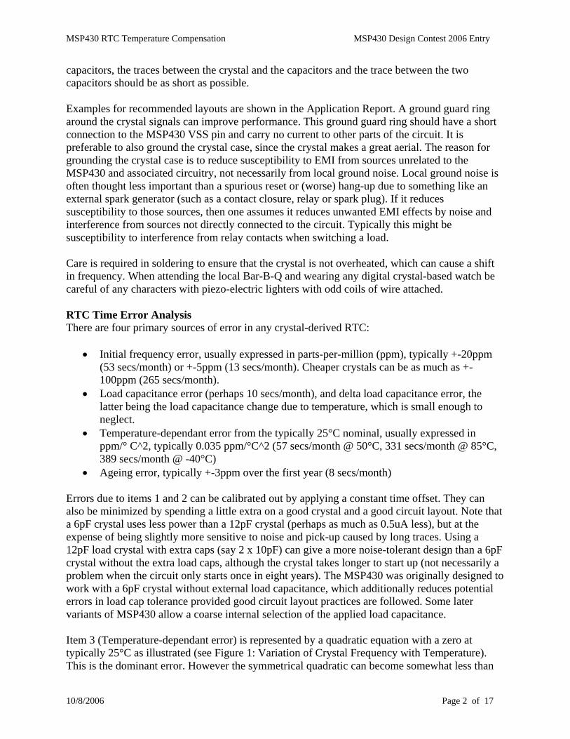
• Ageing error, typically +-3ppm over the first year (8 secs/month) Errors due to items 1 and 2 can be calibrated out by applying a constant time offset. They can also be minimized by spending a little extra on a good crystal and a good circuit layout. Note that a 6pF crystal uses less power than a 12pF crystal (perhaps as much as 0.5uA less), but at the expense of being slightly more sensitive to noise and pick-up caused by long traces. Using a 12pF load crystal with extra caps (say 2 x 10pF) can give a more noise-tolerant design than a 6pF crystal without the extra load caps, although the crystal takes longer to start up (not necessarily a problem when the circuit only starts once in eight years). The MSP430 was originally designed to work with a 6pF crystal without external load capacitance, which additionally reduces potential errors in load cap tolerance provided good circuit layout practices are followed. Some later variants of MSP430 allow a coarse internal selection of the applied load capacitance. Item 3 (Temperature-dependant error) is represented by a quadratic equation with a zero at typically 25°C as illustrated (see Figure 1: Variation of Crystal Frequency with Temperature). This is the dominant error. However the symmetrical quadratic can become somewhat less than
MSP430 RTC Temperature Compensation MSP430 Design Contest 2006 Entry
10/8/2006 Page 3 of 17
symmetrical when power dissipation is taken into account, since a few microwatts doesn’t raise the temperature much at room temperature, but can start to have a noticeable effect at -40°C. This self-heating effect applies individually to both the crystal and the MSP430. Minimising self-heating is desired to both preserve symmetry and to save on battery life. Item 4 must be handled by a periodic calibration, unless of course the crystal manufacturer is kind enough to provide the predicted change in which case it can be automatically adjusted by software, perhaps once per week (see ref. 1). Clearly the dominant error is that due to temperature variation, and this is the error which this discussion will focus on.
RTC Crystal Frequency - Temperature Error (0.035 ppm/'C^2)
y = -0.0011x2 + 0.0573x + 32767
32762
32763
32764
32765
32766
32767
32768
32769
-40 -30 -20 -10 0 10 20 30 40 50 60 70 80 90
Temperature Deg C
Freq
uenc
y (H
z)
0
50
100
150
200
250
300
350
400
Erro
r (Se
cond
s/M
onth
)
Crystal Frequency Uncorrected Error Poly. (Crystal Frequency)
Figure 1: Variation of Crystal Frequency with Temperature Correcting the Temperature Error The first – and perhaps most obvious – approach is to remove the temperature variation. This technique is often used by digital instruments, which maintain the crystal at a high temperature in a temperature-controlled oven (typically a small block of polystyrene foam encasing the crystal with a small heater). Another approach is to keep the crystal in contact with a constant temperature object, which is why a watch keeps better time when worn on the wrist than it does when left on the shelf. However these approaches are not usually viable for an ultra-low power application, since either the heating power cost is too high or there is no convenient constant temperature surface to attach to. There is an excellent discussion of quartz watches in the paper referred to below (see ref. 4). The alternative to controlling the temperature is to instead measure the temperature and provide some form of compensation. Two ways of achieving this are to vary the load capacitance on the crystal or to digitally correct the timer division factor.
MSP430 RTC Temperature Compensation MSP430 Design Contest 2006 Entry
10/8/2006 Page 4 of 17
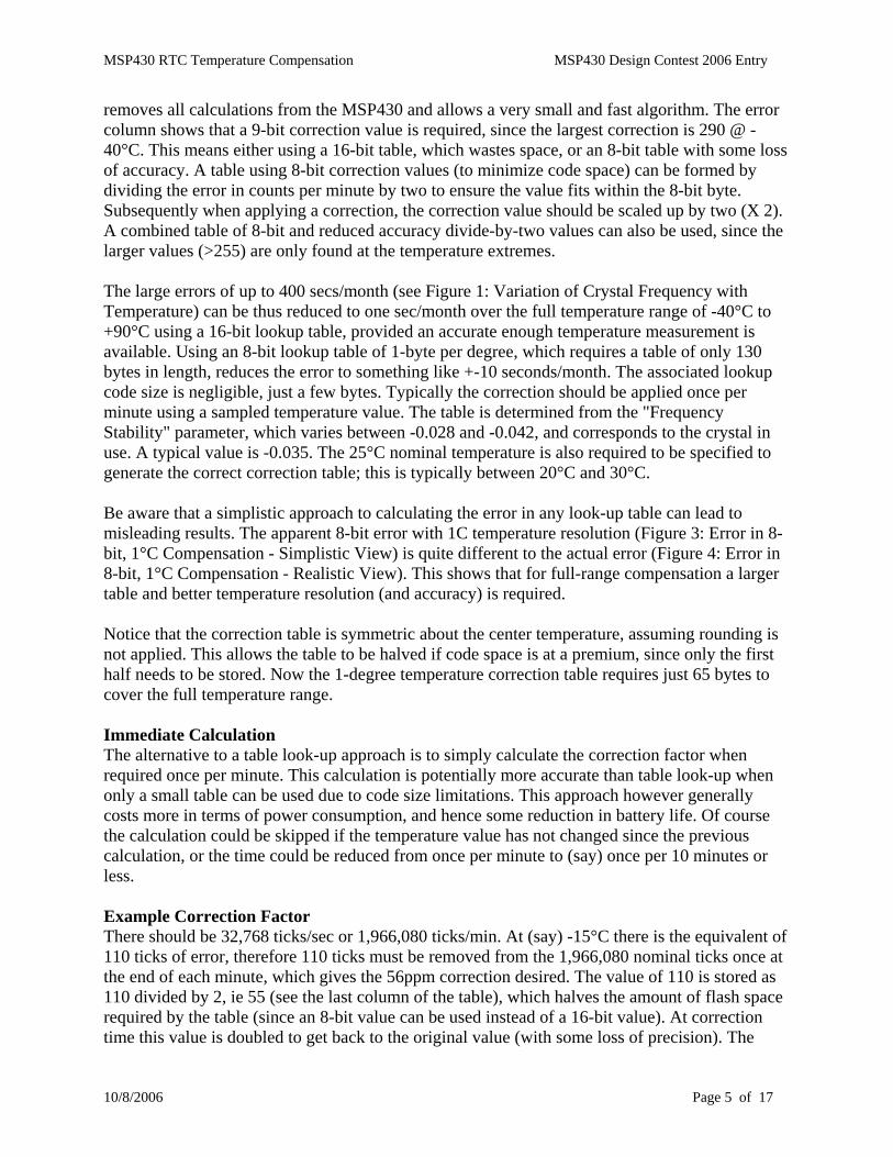
The first alternative makes use of the convenient fact that the crystal frequency can be modified or “pulled” by changing the load capacitance. Increasing the load decreases the frequency, and vice versa. This requires the ability to physically incrementally increase or decrease the load capacitor, which requires either an external circuit - such as a variable capacitance diode, as is used in radio tuning circuits, or FET-switched load capacitor - or the ability to change the load capacitance value within the MSP430. The first option is undesired since it requires additional circuitry on the board. The second option is achievable, but not on all variants of MSP430. Additionally the steps are very coarse, so a variable mark-space ratio of increasing and decreasing the load would be required. Lastly at the temperature extremes there is insufficient adjustment available. These techniques do work, but unfortunately usually require more characterisation of the added hardware. The second alternative doesn’t require any change to the crystal load, but instead simply calculates the accumulated error every 60 seconds or 5 minutes or other convenient interval and applies a fractional correction to the time. Since an increase or decrease in temperature causes a reduction in crystal frequency, this correction can be achieved by lowering the division factor of 32,768 by a calculated amount for (say) the last second in each 60-second interval. Measuring the Temperature The temperature sensor of the MSP430 is measuring the MSP430 die temperature, not the crystal temperature. The MSP430 will have a degree of self-heating which will therefore affect the calibration. Minimising this self-heating is desired to reduce this effect and, as usual, also save on battery life. It is an additional reason to place the crystal as close as possible to the MSP430 device, since it is the temperature of the crystal that is really required. The same argument applies to the crystal self-heating effect. On The Web A Google search of the web – where else? – using the search string “RTC Temperature compensation” reveals an excellent solution by Maxim using their DS32kHz integrated circuit (Ref. 2). The DS32kHz is a Temperature Compensated Crystal Oscillator (TCXO). This TCXO provides a quoted accuracy of +-7.5ppm over the temperature range -40°C to +85°C. It works by measuring the temperature and automatically adjusting the crystal load capacitance once per minute, which is the first option outlined above. This is a good solution, but of course increases product cost and parts count, which is undesirable. Other hits reveal a mixture of both the above alternatives, some correcting once per minute and others up to once per day. Software Correction Software correction is the way to go, since it costs nothing in hardware and can be designed to minimise additional power consumption by doing as little as possible as least often as possible. Code and data size are often also important issues, and not just power consumption, so a variety of solutions are provided. Table Look-Up Correction Usually the fastest, smallest implementation for a correction such as this is via table look-up. The calculation of the compensation factors is off-loaded to an Excel spreadsheet (see Figure 9: Top of Lookup Table from Excel Spreadsheet) and the table itself is exported to the source file. This
MSP430 RTC Temperature Compensation MSP430 Design Contest 2006 Entry
10/8/2006 Page 5 of 17
removes all calculations from the MSP430 and allows a very small and fast algorithm. The error column shows that a 9-bit correction value is required, since the largest correction is 290 @ -40°C. This means either using a 16-bit table, which wastes space, or an 8-bit table with some loss of accuracy. A table using 8-bit correction values (to minimize code space) can be formed by dividing the error in counts per minute by two to ensure the value fits within the 8-bit byte. Subsequently when applying a correction, the correction value should be scaled up by two (X 2). A combined table of 8-bit and reduced accuracy divide-by-two values can also be used, since the larger values (>255) are only found at the temperature extremes. The large errors of up to 400 secs/month (see Figure 1: Variation of Crystal Frequency with Temperature) can be thus reduced to one sec/month over the full temperature range of -40°C to +90°C using a 16-bit lookup table, provided an accurate enough temperature measurement is available. Using an 8-bit lookup table of 1-byte per degree, which requires a table of only 130 bytes in length, reduces the error to something like +-10 seconds/month. The associated lookup code size is negligible, just a few bytes. Typically the correction should be applied once per minute using a sampled temperature value. The table is determined from the "Frequency Stability" parameter, which varies between -0.028 and -0.042, and corresponds to the crystal in use. A typical value is -0.035. The 25°C nominal temperature is also required to be specified to generate the correct correction table; this is typically between 20°C and 30°C. Be aware that a simplistic approach to calculating the error in any look-up table can lead to misleading results. The apparent 8-bit error with 1C temperature resolution (Figure 3: Error in 8-bit, 1°C Compensation - Simplistic View) is quite different to the actual error (Figure 4: Error in 8-bit, 1°C Compensation - Realistic View). This shows that for full-range compensation a larger table and better temperature resolution (and accuracy) is required. Notice that the correction table is symmetric about the center temperature, assuming rounding is not applied. This allows the table to be halved if code space is at a premium, since only the first half needs to be stored. Now the 1-degree temperature correction table requires just 65 bytes to cover the full temperature range. Immediate Calculation The alternative to a table look-up approach is to simply calculate the correction factor when required once per minute. This calculation is potentially more accurate than table look-up when only a small table can be used due to code size limitations. This approach however generally costs more in terms of power consumption, and hence some reduction in battery life. Of course the calculation could be skipped if the temperature value has not changed since the previous calculation, or the time could be reduced from once per minute to (say) once per 10 minutes or less. Example Correction Factor There should be 32,768 ticks/sec or 1,966,080 ticks/min. At (say) -15°C there is the equivalent of 110 ticks of error, therefore 110 ticks must be removed from the 1,966,080 nominal ticks once at the end of each minute, which gives the 56ppm correction desired. The value of 110 is stored as 110 divided by 2, ie 55 (see the last column of the table), which halves the amount of flash space required by the table (since an 8-bit value can be used instead of a 16-bit value). At correction time this value is doubled to get back to the original value (with some loss of precision). The

MSP430 RTC Temperature Compensation MSP430 Design Contest 2006 Entry
10/8/2006 Page 6 of 17
error by doing this is indicted in the 2nd column of "Cal Error", given in seconds per month. The flash lookup-table therefore comprises a singe 8-bit byte correction factor per degree C. Algorithms in C Timer_A1 is used to generate the timing for the RTC. First some constant definitions, the first two are specific to the crystal in use: // The error correction of +3 is for about +12.5 seconds of error in 38hrs 17mins // Error reduced to -1 second in 48 hours using 3, so use 2 + delta // ie total unadjusted error approx 14.67 seconds per 48 hours // -> 2.78187 -> 2 plus 47 counts/minute #define TIMER_A_RESET_TIME (32767+2) // (32768-1) 1 second tick @ 32.768KHz plus error #define TIMER_A_DELTA_TIME (47) // delta adjust every minute (add temp correction) typedef unsigned char byte; typedef unsigned short uint16; #if defined (OPTION_USING_TEMPERATURE_COMPENSATION_FOR_RTC) #define MIN_RTC_CALIBRATION_TEMP (-40) // degrees C, lowest value #define CENTER_RTC_CALIBRATION_TEMP ( 25) // degrees C, zero cal value #define MAX_RTC_CALIBRATION_TEMP ( 90) // degrees C, maximum value // zero cal index at (typically) 25 degrees C #define CENTER_RTC_CALIBRATION_INDEX (CENTER_RTC_CALIBRATION_TEMP-MIN_RTC_CALIBRATION_TEMP)
Here is a typical initialization for Timer_A1: void InitialiseTimerA1( void ) { /* * Initialize Timer_A-1 for 1 interrupt per second */ CCR0 = TIMER_A_RESET_TIME; // set toggle freq (typ. 1 Hz) CCR1 = TIMER_A_RESET_TIME/2; // set toggle freq (typ. 1 Hz) CCR2 = TIMER_A_RESET_TIME/2; // set toggle freq (typ. 1 Hz) // Capture/Compare Register 1: Output Mode 7 (PWM reset/set), Compare CCTL1 = OUTMOD_7; // Capture/Compare Register 2: Output Mode 3 (PWM set/reset), Compare CCTL2 = OUTMOD_3; // Select ACLK, divide by 1, clear counter, Start Timer_A & repeated count // to CCR0, enable interrupts TACTL = ( TASSEL_1 | ID_0 | MC_1 | TAIE ); // Enable CCR0 interrupt in compare mode, toggle output CCTL0 = ( OUTMOD_4 | CCIE ); RtcCorrectionTime = (FrequencyCorrectionTable[CENTER_RTC_CALIBRATION_INDEX] << 1) - TIMER_A_DELTA_TIME; }
The lookup table is typically defined as follows. Only the last column generates any data, the other columns are simply comments. const byte FrequencyCorrectionTable[] = { /* 16-bit 8-bit */ /* Table Temp Actual Error Error Error Table Table */ /* Index Deg Frequency ppm counts secs Value Value */ /* C Hz /min /Month */ /* 0 -40 32763.15 147.88 290.73 388.62 291 */ 145, /* 1 -39 32763.30 143.36 281.86 376.75 282 */ 141, <snip> /* 128 88 32763.45 138.92 273.12 365.07 273 */ 136,
MSP430 RTC Temperature Compensation MSP430 Design Contest 2006 Entry
10/8/2006 Page 7 of 17
/* 129 89 32763.30 143.36 281.86 376.75 282 */ 141, /* 130 90 32763.15 147.88 290.73 388.62 291 */ 145 }; #define NUMBER_OF_RTC_CAL_ENTRIES (sizeof(FrequencyCorrectionTable)/sizeof(FrequencyCorrectionTable[0])) Once per minute the following correction is prepared in the background main loop: RtcCorrectionTime = (FrequencyCorrectionTable[RtcCorrectionIndex] << 1) - TIMER_A_DELTA_TIME; Once per minute the actual adjustment is performed within the Timer_A1 isr: // Check temperature compensation once per minute if (UpdateTempCorrectionFlag) { // Set toggle freq to reduced value to compensate for temperature CCR0 = TIMER_A_RESET_TIME - RtcCorrectionTime; UpdateTempCorrectionFlag = 0; } else { // Set toggle freq back to nominal value (typ. 8 Hz) CCR0 = TIMER_A_RESET_TIME; } See the source code for more details on how the table is used. C Compilers There are three MSP430 compilers which I have used extensively, from Crossworks, Quadravox and IAR. Crossworks is an excellent choice when considering code generation and general features when working in a professional environment. Quadravox is much simpler to use, having fewer options, but doesn't generate quite so compact code; it is also cheaper. IAR is highly priced and suffers from extremely poor support in the sense that once the paid subscription expires one is not entitled to updates; however it generates very good code and of course comes packaged with the TI MSP430 Development Kits. Crossworks and Quadravox are both very well supported with almost instant code fixes to reported problems. I recommend them both highly. There are also others listed on the TI web site. These include Imagecraft (which has had good reports), GCC (which is free, but can have ownership implications when using some library code), and possibly also HiTech. Most (actually I think all) the compilers allow a 30-day trial just by downloading. Code examples for both IAR and Quadravox are included with this entry. It is a simple matter to compile for other compilers. Now it’s time to look at the errors in the compensation algorithm in more detail.
MSP430 RTC Temperature Compensation MSP430 Design Contest 2006 Entry
10/8/2006 Page 8 of 17
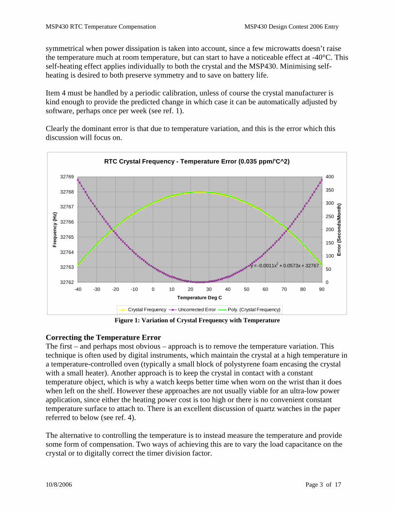
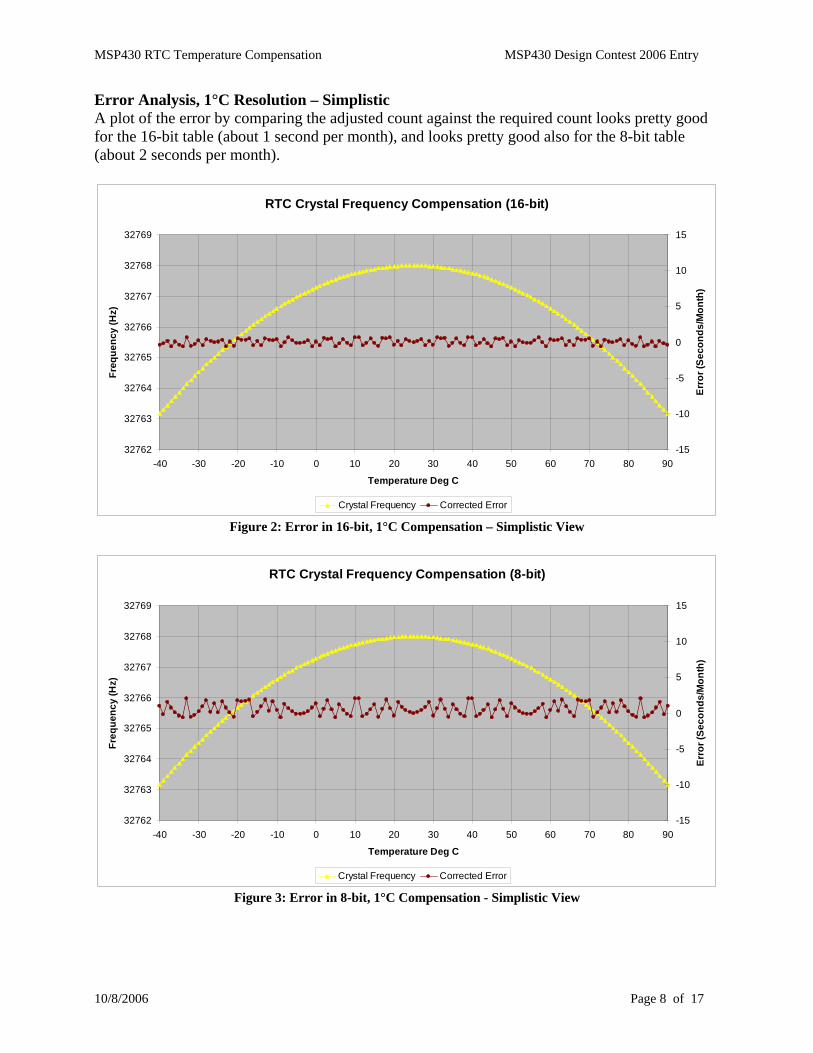
Error Analysis, 1°C Resolution – Simplistic A plot of the error by comparing the adjusted count against the required count looks pretty good for the 16-bit table (about 1 second per month), and looks pretty good also for the 8-bit table (about 2 seconds per month).
RTC Crystal Frequency Compensation (16-bit)
32762
32763
32764
32765
32766
32767
32768
32769
-40 -30 -20 -10 0 10 20 30 40 50 60 70 80 90
Temperature Deg C
Freq
uenc
y (H
z)
-15
-10
-5
0
5
10
15
Erro
r (Se
cond
s/M
onth
)
Crystal Frequency Corrected Error Figure 2: Error in 16-bit, 1°C Compensation – Simplistic View
RTC Crystal Frequency Compensation (8-bit)
32762
32763
32764
32765
32766
32767
32768
32769
-40 -30 -20 -10 0 10 20 30 40 50 60 70 80 90
Temperature Deg C
Freq
uenc
y (H
z)
-15
-10
-5
0
5
10
15
Erro
r (Se
cond
s/M
onth
)
Crystal Frequency Corrected Error Figure 3: Error in 8-bit, 1°C Compensation - Simplistic View
MSP430 RTC Temperature Compensation MSP430 Design Contest 2006 Entry
10/8/2006 Page 9 of 17
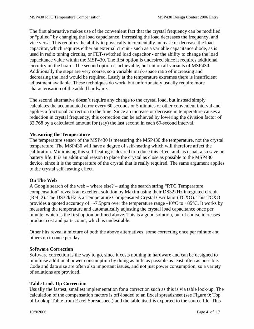
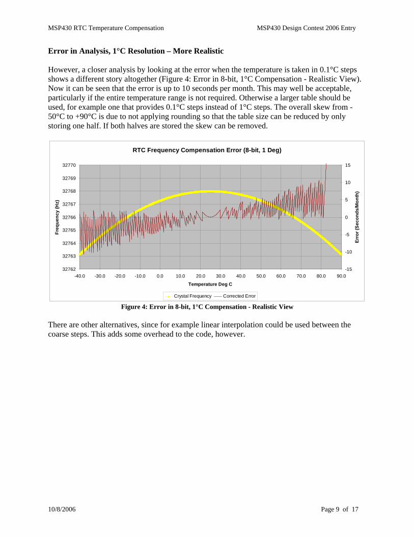
Error in Analysis, 1°C Resolution – More Realistic However, a closer analysis by looking at the error when the temperature is taken in 0.1°C steps shows a different story altogether (Figure 4: Error in 8-bit, 1°C Compensation - Realistic View). Now it can be seen that the error is up to 10 seconds per month. This may well be acceptable, particularly if the entire temperature range is not required. Otherwise a larger table should be used, for example one that provides 0.1°C steps instead of 1°C steps. The overall skew from -50°C to +90°C is due to not applying rounding so that the table size can be reduced by only storing one half. If both halves are stored the skew can be removed.
RTC Frequency Compensation Error (8-bit, 1 Deg)
32762
32763
32764
32765
32766
32767
32768
32769
32770
-40.0 -30.0 -20.0 -10.0 0.0 10.0 20.0 30.0 40.0 50.0 60.0 70.0 80.0 90.0
Temperature Deg C
Freq
uenc
y (H
z)
-15
-10
-5
0
5
10
15
Erro
r (Se
cond
s/M
onth
)
Crystal Frequency Corrected Error Figure 4: Error in 8-bit, 1°C Compensation - Realistic View
There are other alternatives, since for example linear interpolation could be used between the coarse steps. This adds some overhead to the code, however.
MSP430 RTC Temperature Compensation MSP430 Design Contest 2006 Entry
10/8/2006 Page 10 of 17
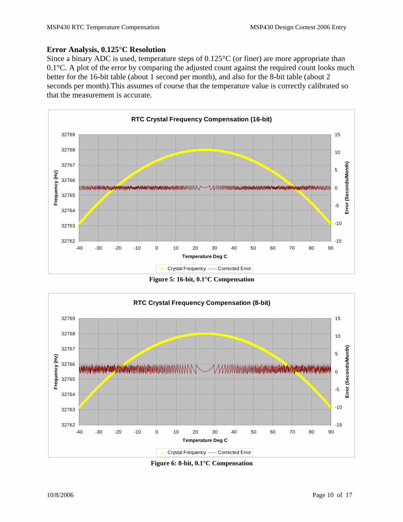
Error Analysis, 0.125°C Resolution Since a binary ADC is used, temperature steps of 0.125°C (or finer) are more appropriate than 0.1°C. A plot of the error by comparing the adjusted count against the required count looks much better for the 16-bit table (about 1 second per month), and also for the 8-bit table (about 2 seconds per month).This assumes of course that the temperature value is correctly calibrated so that the measurement is accurate.
RTC Crystal Frequency Compensation (16-bit)
32762
32763
32764
32765
32766
32767
32768
32769
-40 -30 -20 -10 0 10 20 30 40 50 60 70 80 90
Temperature Deg C
Freq
uenc
y (H
z)
-15
-10
-5
0
5
10
15
Erro
r (Se
cond
s/M
onth
)
Crystal Frequency Corrected Error Figure 5: 16-bit, 0.1°C Compensation
RTC Crystal Frequency Compensation (8-bit)
32762
32763
32764
32765
32766
32767
32768
32769
-40 -30 -20 -10 0 10 20 30 40 50 60 70 80 90
Temperature Deg C
Freq
uenc
y (H
z)
-15
-10
-5
0
5
10
15
Erro
r (Se
cond
s/M
onth
)
Crystal Frequency Corrected Error Figure 6: 8-bit, 0.1°C Compensation
MSP430 RTC Temperature Compensation MSP430 Design Contest 2006 Entry
10/8/2006 Page 11 of 17
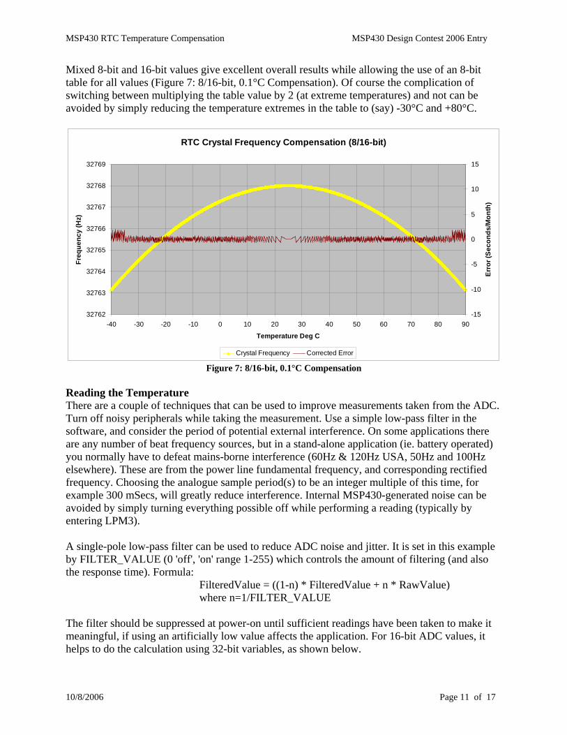
Mixed 8-bit and 16-bit values give excellent overall results while allowing the use of an 8-bit table for all values (Figure 7: 8/16-bit, 0.1°C Compensation). Of course the complication of switching between multiplying the table value by 2 (at extreme temperatures) and not can be avoided by simply reducing the temperature extremes in the table to (say) -30°C and +80°C.
RTC Crystal Frequency Compensation (8/16-bit)
32762
32763
32764
32765
32766
32767
32768
32769
-40 -30 -20 -10 0 10 20 30 40 50 60 70 80 90
Temperature Deg C
Freq
uenc
y (H
z)
-15
-10
-5
0
5
10
15
Erro
r (Se
cond
s/M
onth
)
Crystal Frequency Corrected Error Figure 7: 8/16-bit, 0.1°C Compensation
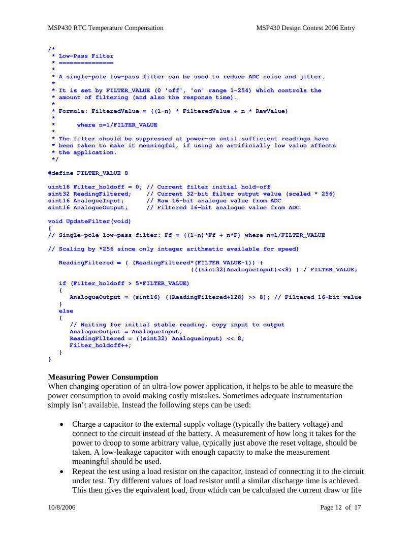
Reading the Temperature There are a couple of techniques that can be used to improve measurements taken from the ADC. Turn off noisy peripherals while taking the measurement. Use a simple low-pass filter in the software, and consider the period of potential external interference. On some applications there are any number of beat frequency sources, but in a stand-alone application (ie. battery operated) you normally have to defeat mains-borne interference (60Hz & 120Hz USA, 50Hz and 100Hz elsewhere). These are from the power line fundamental frequency, and corresponding rectified frequency. Choosing the analogue sample period(s) to be an integer multiple of this time, for example 300 mSecs, will greatly reduce interference. Internal MSP430-generated noise can be avoided by simply turning everything possible off while performing a reading (typically by entering LPM3). A single-pole low-pass filter can be used to reduce ADC noise and jitter. It is set in this example by FILTER_VALUE (0 'off', 'on' range 1-255) which controls the amount of filtering (and also the response time). Formula: FilteredValue = ((1-n) * FilteredValue + n * RawValue) where n=1/FILTER_VALUE The filter should be suppressed at power-on until sufficient readings have been taken to make it meaningful, if using an artificially low value affects the application. For 16-bit ADC values, it helps to do the calculation using 32-bit variables, as shown below.
MSP430 RTC Temperature Compensation MSP430 Design Contest 2006 Entry
10/8/2006 Page 12 of 17
/* * Low-Pass Filter * =============== * * A single-pole low-pass filter can be used to reduce ADC noise and jitter. * * It is set by FILTER_VALUE (0 'off', 'on' range 1-254) which controls the * amount of filtering (and also the response time). * * Formula: FilteredValue = ((1-n) * FilteredValue + n * RawValue) * * where n=1/FILTER_VALUE * * The filter should be suppressed at power-on until sufficient readings have * been taken to make it meaningful, if using an artificially low value affects * the application. */ #define FILTER_VALUE 8 uint16 Filter_holdoff = 0; // Current filter initial hold-off sint32 ReadingFiltered; // Current 32-bit filter output value (scaled * 256) sint16 AnalogueInput; // Raw 16-bit analogue value from ADC sint16 AnalogueOutput; // Filtered 16-bit analogue value from ADC void UpdateFilter(void) { // Single-pole low-pass filter: Ff = ((1-n)*Ff + n*F) where n=1/FILTER_VALUE // Scaling by *256 since only integer arithmetic available for speed) ReadingFiltered = ( (ReadingFiltered*(FILTER_VALUE-1)) + (((sint32)AnalogueInput)<<8) ) / FILTER_VALUE; if (Filter_holdoff > 5*FILTER_VALUE) { AnalogueOutput = (sint16) ((ReadingFiltered+128) >> 8); // Filtered 16-bit value } else { // Waiting for initial stable reading, copy input to output AnalogueOutput = AnalogueInput; ReadingFiltered = ((sint32) AnalogueInput) << 8; Filter_holdoff++; } }
Measuring Power Consumption When changing operation of an ultra-low power application, it helps to be able to measure the power consumption to avoid making costly mistakes. Sometimes adequate instrumentation simply isn’t available. Instead the following steps can be used:
• Charge a capacitor to the external supply voltage (typically the battery voltage) and connect to the circuit instead of the battery. A measurement of how long it takes for the power to droop to some arbitrary value, typically just above the reset voltage, should be taken. A low-leakage capacitor with enough capacity to make the measurement meaningful should be used.
• Repeat the test using a load resistor on the capacitor, instead of connecting it to the circuit under test. Try different values of load resistor until a similar discharge time is achieved. This then gives the equivalent load, from which can be calculated the current draw or life
MSP430 RTC Temperature Compensation MSP430 Design Contest 2006 Entry
10/8/2006 Page 13 of 17
of a battery.
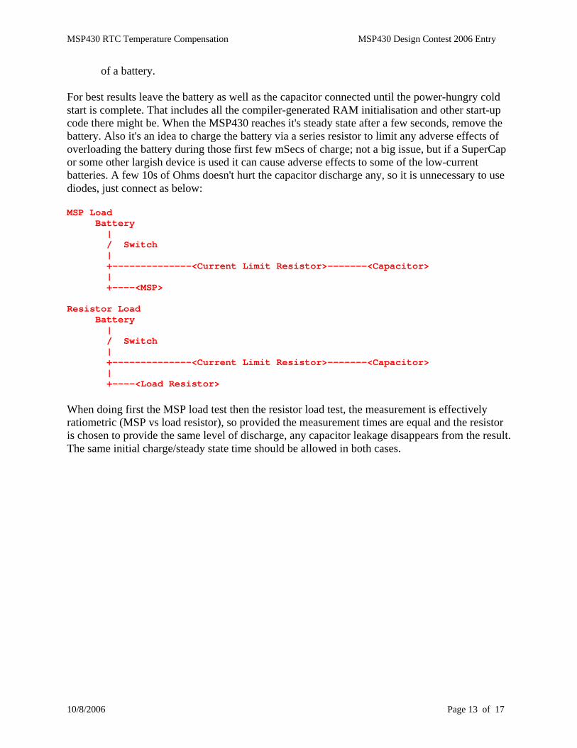
For best results leave the battery as well as the capacitor connected until the power-hungry cold start is complete. That includes all the compiler-generated RAM initialisation and other start-up code there might be. When the MSP430 reaches it's steady state after a few seconds, remove the battery. Also it's an idea to charge the battery via a series resistor to limit any adverse effects of overloading the battery during those first few mSecs of charge; not a big issue, but if a SuperCap or some other largish device is used it can cause adverse effects to some of the low-current batteries. A few 10s of Ohms doesn't hurt the capacitor discharge any, so it is unnecessary to use diodes, just connect as below: MSP Load Battery | / Switch | +--------------<Current Limit Resistor>-------<Capacitor> | +----<MSP> Resistor Load Battery | / Switch | +--------------<Current Limit Resistor>-------<Capacitor> | +----<Load Resistor> When doing first the MSP load test then the resistor load test, the measurement is effectively ratiometric (MSP vs load resistor), so provided the measurement times are equal and the resistor is chosen to provide the same level of discharge, any capacitor leakage disappears from the result. The same initial charge/steady state time should be allowed in both cases.
MSP430 RTC Temperature Compensation MSP430 Design Contest 2006 Entry
10/8/2006 Page 14 of 17
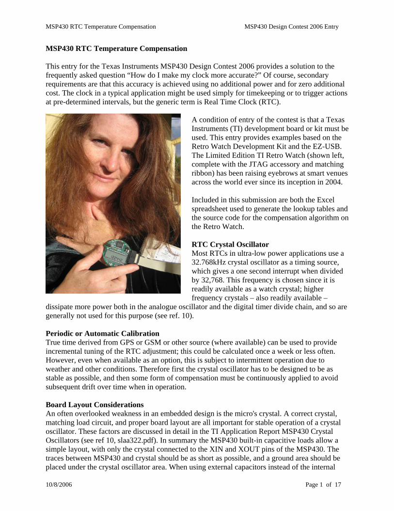
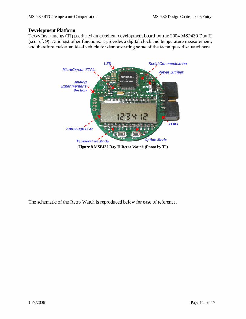
Development Platform Texas Instruments (TI) produced an excellent development board for the 2004 MSP430 Day II (see ref. 9). Amongst other functions, it provides a digital clock and temperature measurement, and therefore makes an ideal vehicle for demonstrating some of the techniques discussed here.
Figure 8 MSP430 Day II Retro Watch (Photo by TI)
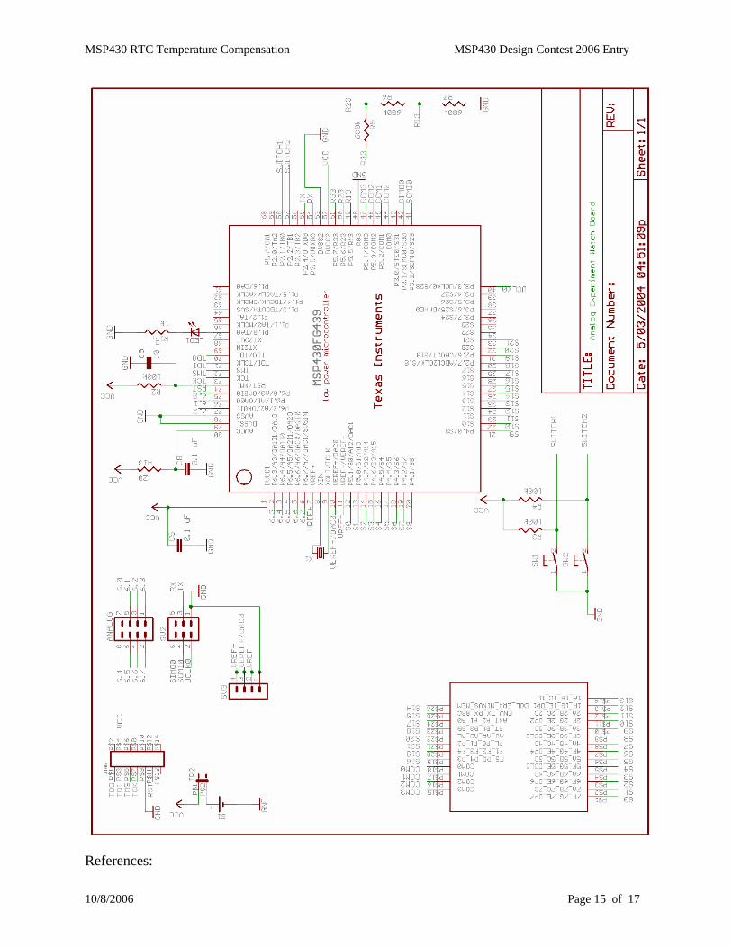
The schematic of the Retro Watch is reproduced below for ease of reference.
Temperature Mode Option Mode
JTAG
LED MicroCrystal XTAL
Analog Experimenter’s
Section
Serial Communication
Softbaugh LCD
MSP430F437or
MSP430FG439
Power Jumper
MSP430 RTC Temperature Compensation MSP430 Design Contest 2006 Entry
10/8/2006 Page 15 of 17
References:
MSP430 RTC Temperature Compensation MSP430 Design Contest 2006 Entry
10/8/2006 Page 16 of 17
1. Quartz Crystal Oscillators and Resonators by John Vig http://www.ieee-uffc.org/freqcontrol/tutorials/vig2/tutorial2_files/frame.htm
2. Dallas Application Note 3566: Timekeeping Accuracy, Automatic and Affordable http://www.maxim-ic.com/appnotes.cfm/an_pk/3566
3. Crystal Considerations for Dallas Real-Time Clocks 4. Thermocompensated Quartz Watches and their Movements
http://forums.watchuseek.com/showthread.php?t=2087 5. Aging in Quartz Oscillators http://www.ieee-uffc.org/freqcontrol/vigaging91/aging.htm 6. Epson Oscillator Design Guide 7. Micro Crystal Data Sheet 8. MSP430 LFXT1 Oscillator Accuracy by TI (slaa225) 9. MSP430 Day II 2004 by TI (slac037a.zip) 10. MSP430 Crystal Oscillators by TI (slaa322.pdf) 11. Quadravox MSP430 C Compiler http://www.quadravox.com 12. CrossStudio MSP430 C Compiler http://www.rowley.co.uk
MSP430 RTC Temperature Compensation MSP430 Design Contest 2006 Entry
10/8/2006 Page 17 of 17
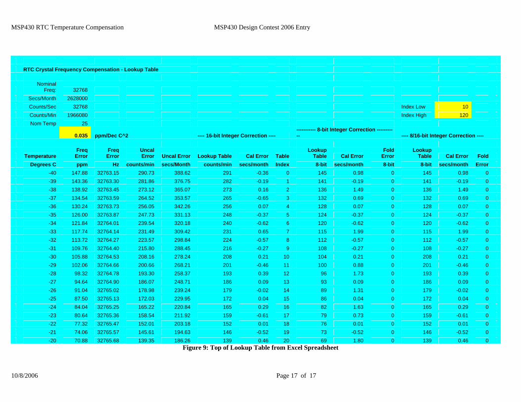
RTC Crystal Frequency Compensation - Lookup Table
Nominal
Freq: 32768 Secs/Month 2628000 Counts/Sec 32768 Index Low 10 Counts/Min 1966080 Index High 120 Nom Temp 25
0.035 ppm/Dec C^2 ---- 16-bit Integer Correction ---- ----------- 8-bit Integer Correction ----------- ---- 8/16-bit Integer Correction ----
Temperature Freq
Error Freq
Error Uncal Error Uncal Error Lookup Table Cal Error Table
Lookup Table Cal Error
Fold Error
Lookup Table Cal Error Fold
Degrees C ppm Hz counts/min secs/Month counts/min secs/month Index 8-bit secs/month 8-bit 8-bit secs/month Error -40 147.88 32763.15 290.73 388.62 291 -0.36 0 145 0.98 0 145 0.98 0 -39 143.36 32763.30 281.86 376.75 282 -0.19 1 141 -0.19 0 141 -0.19 0 -38 138.92 32763.45 273.12 365.07 273 0.16 2 136 1.49 0 136 1.49 0 -37 134.54 32763.59 264.52 353.57 265 -0.65 3 132 0.69 0 132 0.69 0 -36 130.24 32763.73 256.05 342.26 256 0.07 4 128 0.07 0 128 0.07 0 -35 126.00 32763.87 247.73 331.13 248 -0.37 5 124 -0.37 0 124 -0.37 0 -34 121.84 32764.01 239.54 320.18 240 -0.62 6 120 -0.62 0 120 -0.62 0 -33 117.74 32764.14 231.49 309.42 231 0.65 7 115 1.99 0 115 1.99 0 -32 113.72 32764.27 223.57 298.84 224 -0.57 8 112 -0.57 0 112 -0.57 0 -31 109.76 32764.40 215.80 288.45 216 -0.27 9 108 -0.27 0 108 -0.27 0 -30 105.88 32764.53 208.16 278.24 208 0.21 10 104 0.21 0 208 0.21 0 -29 102.06 32764.66 200.66 268.21 201 -0.46 11 100 0.88 0 201 -0.46 0 -28 98.32 32764.78 193.30 258.37 193 0.39 12 96 1.73 0 193 0.39 0 -27 94.64 32764.90 186.07 248.71 186 0.09 13 93 0.09 0 186 0.09 0 -26 91.04 32765.02 178.98 239.24 179 -0.02 14 89 1.31 0 179 -0.02 0 -25 87.50 32765.13 172.03 229.95 172 0.04 15 86 0.04 0 172 0.04 0 -24 84.04 32765.25 165.22 220.84 165 0.29 16 82 1.63 0 165 0.29 0 -23 80.64 32765.36 158.54 211.92 159 -0.61 17 79 0.73 0 159 -0.61 0 -22 77.32 32765.47 152.01 203.18 152 0.01 18 76 0.01 0 152 0.01 0 -21 74.06 32765.57 145.61 194.63 146 -0.52 19 73 -0.52 0 146 -0.52 0 -20 70.88 32765.68 139.35 186.26 139 0.46 20 69 1.80 0 139 0.46 0
Figure 9: Top of Lookup Table from Excel Spreadsheet