MSD MEDIUM VOLTAGE CAPACITORS - Westek Electronics€¦ · voltage for capacitor fuses – Course...
32
ISSUE_AUSGABE 2007 3 MSD MEDIUM VOLTAGE CAPACITORS MSD MITTELSPANNUNGSKONDENSATOREN ELECTRONICON KONDENSATOREN GMBH GERA · GERMANY
Transcript of MSD MEDIUM VOLTAGE CAPACITORS - Westek Electronics€¦ · voltage for capacitor fuses – Course...
ISSU
E_A
USG
AB
E 20
07
3
MSD MEDIUM VOLTAGECAPACITORS MSD MITTELSPANNUNGSKONDENSATOREN
ELECTRONICON KONDENSATOREN GMBH GERA · GERMANY
4

TAB
LE O
F C
ON
TEN
TS_I
NH
ALT
5
INTRODUCTION . . . . . . . . . . . . . . . . . . . . . . . . . . . . 7Basics of power factor correction – Calculation
of required capacitor power – Influence of harmonics,
Harmonic filtering
COMPARISON OF CONVENTIONAL MEDIUM VOLTAGE CAPACITORS AND ENGINEERING TECHNIQUES . . . . . . . . . . . . . . . . . . . . . . . . . . . . . . 11
Operational stress of ALLFILM capacitors – Objective
of capacitor protection techniques – Breakdown
behaviour of ALLFILM capacitors – 3phase MV capacitors
RISKS AND SHORTCOMINGS OFFORMER COMMON CONCEPTS . . . . . . . . . . . . . . 13
Choice of nominal fuse current – Selection of the rated
voltage for capacitor fuses – Course of damage at capacitors
with winding fuses – Correct handling of fault tripping
MSD – SELF-HEALING MEDIUM VOLTAGECAPACITORS IN DRY TECHNOLOGY . . . . . . . . . . 19
Design and characteristics – Benefits – Economic
viability – Application
DEFINITIONS AND SELECTION CRITERIA . . . . . 22Voltage ratings – Test voltages – Rated power –
Current ratings – Temperature categories
MOUNTING AND OPERATING INSTRUCTIONS . . . . . . . . . . . . . . . . . . . . . . . . . . . 24
Mounting position – Mounting location/Cooling –
Vibration stress – Connection – Fixing torque –
Discharge – Earthing – Environmental compatibility –
Disposal
SAFETY . . . . . . . . . . . . . . . . . . . . . . . . . . . . . . . . . . 27Self-Healing Dielectric – Protection Against
Accidental Contact – Protection against Overload
GENERAL TECHNICAL DATA . . . . . . . . . . . . . . . . 28
DATA CHARTS MSD E90.xxx
3.15...3.6kV 50Hz . . . . . . . . . . . . . . . . . . . . . . . . . . . . . . . . . . . . 29
6.3...7.1kV 50Hz . . . . . . . . . . . . . . . . . . . . . . . . . . . . . . . . . . . . . 30
10.5...11.8kV 50Hz . . . . . . . . . . . . . . . . . . . . . . . . . . . . . . . . . . . 31
2.4...4.16kV 60Hz . . . . . . . . . . . . . . . . . . . . . . . . . . . . . . . . . . . . 32
EINFÜHRUNG . . . . . . . . . . . . . . . . . . . . . . . . . . . . . . 7Grundlagen der Blindleistungskompensation –
Berechnung der benötigten Kondensatorleistung –
Einfluss von Oberwellen und deren Filterung
MITTELSPANNUNGSKONDENSATOREN-UND ANLAGENTECHNIKEN IM VERGLEICH . . . . 11
Betriebsbeanspruchung von ALLFILM Kondensatoren –
Zielsetzung der Kondensatorschutztechnik – Ausfall-
verhalten von ALLFILM Kondensatoren – 3-phasige Mittel-
spannungskondensatoren
RISIKEN UND UNZUGÄNGLICHKEITEN DERBISHER GEBRÄUCHLICHEN KONZEPTE . . . . . . . 13
Wahl des Sicherungsnennstroms – Wahl der Nenn-
spannung von Kondensatorsicherungen – Schadens-
verlauf bei Kondensatoren mit Wickelsicherungen –
Richtiger Umgang mit Schutzauslösungen
MSD – SELBSTHEILENDEMITTELSPANNUNGSKONDENSATORENIN TROCKENTECHNOLOGIE . . . . . . . . . . . . . . . . . 19
Aufbau und Eigenschaften – Vorteile –
Wirtschaftlichkeit – Anwendung
BEGRIFFE UND AUSWAHLKRITERIEN . . . . . . . . 22Nennspannung – Netznennspannung – Prüfspannung –
Isolationsspannung – Nennleistung – Stufenleistung –
Nennstrom – Effektivstrom – Stoßstromfestigkeit –
Temperaturklasse
VORSCHRIFTEN ZU EINBAU UND BETRIEB . . . . 24Einbaulage – Einbauort/Kühlung –
Schwingungsbelastung – Anschluss – Anzugs-
Drehmomente – Entladung – Erdung –
Umweltverträglichkeit, Entsorgung
SICHERHEIT DER KONDENSATOREN . . . . . . . . . 27Selbstheilendes Dielektrikum – Berührungssicher-
heit – Schutz gegen Überlastung
ALLGEMEINE TECHNISCHE ANGABEN . . . . . . . 28
DATENTABELLEN MSD E90.xxx
3.15...3.6kV 50Hz . . . . . . . . . . . . . . . . . . . . . . . . . . . . . . . . . . . . 29
6.3...7.1kV 50Hz . . . . . . . . . . . . . . . . . . . . . . . . . . . . . . . . . . . . . 30
10.5...11.8kV 50Hz . . . . . . . . . . . . . . . . . . . . . . . . . . . . . . . . . . . 31
2.4...4.16kV 60Hz . . . . . . . . . . . . . . . . . . . . . . . . . . . . . . . . . . . . 32

6
INTRODUCTIONEINFÜHRUNG
INTR
OD
UCT
ION
_EIN
LEIT
UN
G
7
Basics of Power Factor Correction
Under normal operating conditions certain electrical loads (e.g. induction motors, welding equipment, arc furnaces and fluorescent lighting) draw not only active power from the supply, but also inductive reactive power (kvar). This reactive power is necessary for the equipment to operate correctly but could be interpreted as an undesirable burden on the supply. The power factor of a load is defined as the ratio of active power to apparent power, i.e. kW:kVA and is referred to as cosϕ. The closer cosϕ is to unity, the less reactive power is drawn from the supply:
The transmission of a certain effective power at a cosϕ = 0.6 requires a current approx. 1.67 times higher than with a cosϕ = 1. Accordingly, distribution and transmission equipment as well as feeding transformers have to be derated for this higher load. Furthermore their useful life may also be decreased.
! For systems with a low power factor the transmission of electric power in accordance with existing standards results in higher expenses both for the supply distribution companies and the consumer.
Another reason for higher costs are the losses incurred via heat dissipation in the cables caused by the overall current of the system as well as via the windings of both transformers and generators. In our above example the power dissipated would increase by approx. 180%.
! In general terms, as the power factor of a three phase system decreases, the current rises. The heat dissipation in the system rises proportionately by a factor equivalent to the square of the current rise.
This is the main reason why Electricity Supply Companies in modern economies demand reduction of the reactive load in their networks via improvement of the power factor. In most cases, special reactive current tariffs penalise consumers for poor power factor.
> Conclusion:
• A reduction in the overall cost of electricity can be achieved by improving the power factor to a more economic level.
• The supply will be able to support additional load which may be of benefit for expanding companies.
• Reducing the load on distribution network components by power factor improvement will result in an extension of their useful life.
Grundlagen der Blindleistungskompensation
Unter normalen Betriebsbedingungen entnehmen elektrische Verbraucher, deren Betrieb durch den Auf- und Abbau von magnetischen Feldern begleitet wird (z.B. Induktionsmotoren, Schweißausrüstungen, Lichtbögen und Fluoreszenzleuchten) dem Netz nicht nur Wirkleistung, sondern auch induktive Blindleistung (kvar). Diese Blindleistung ist für die Funktion der Ausrüstung erforderlich, kann gleichzeitig jedoch als unerwünschte Belastung des Netzes interpretiert werden. Der Leistungsfaktor eines Verbrauchers ist als das Verhältnis von umgesetzter Wirkleistung zu dem Netz tatsächlich entnommener Scheinleistung (kW zu kvar) definiert und wird bezeichnet als cosϕ. Je näher der cosϕ bei eins liegt, um so geringer ist der Anteil von Blindleistung, die dem Netz entnommen wird.
Bei einem cosϕ = 0.6 erhöht sich der benötigte Strom für die Übertragung einer bestimmten Wirkleistung in etwa um den Faktor 1.67 im Vergleich zum benötigten Strom bei einem cosϕ = 1. Dementsprechend müssen Einspeisungs-, Übertragungs- und Verteilungseinrichtungen stärker dimensioniert werden. Außerdem kann ihre Nutzungsdauer durch die größere Belastung herabgesetzt werden.
! In Systemen mit einem niedrigen Leistungsfaktor erfordert die stan-dardgerechte Übertragung von Elektroenergie verbraucherseitig und generatorseitig erhöhte Aufwendungen.
Ein weiterer kostensteigernder Faktor ist die durch den erhöhten Gesamtstrom hervorgerufene Wärmeentwicklung in Kabeln und anderen Verteileinrichtungen, in Transformatoren und Generatoren. Im oben genannten Beispiel würde sich gleichzeitig die Verlustleistung im System um ca. 180% erhöhen.
! Mit sich verringerndem cosϕ und damit steigendem Strom steigt die Verlustleistung in einem Dreiphasennetz quadratisch an.
Das oben genannte ist der Hauptgrund dafür, dass die Energieversorgungs-unternehmen moderner Volkswirtschaften eine Reduzierung der Blindlast in ihren Versorgungsnetzen durch Verbesserung des Leistungsfaktors verlangen. In der Regel werden Verbraucher mit einem niedrigen Leistungsfaktor durch spezielle Blindleistungstarife belastet.
> Fazit:
• Der Verbraucher kann durch Verbesserung seines Leistungsfaktors eine Verringerung der Gesamtkosten für Elektrizität erreichen.
• Eine Verringerung der Blindlast ermöglicht es dem Versorger, mit gleicher Kapazität zusätzliche Nutzlast zu versorgen, welches für expandierende Unternehmen von Nutzen sein kann.
• Die Verbesserung des Leistungsfaktors reduziert die Belastung der Komponenten des Verteilernetzes. Dies erhöht ihre Lebensdauer.

INTR
OD
UCT
ION
_EIN
LEIT
UN
G
8
Types of Power Factor Correction
A capacitive reactive power resulting from the connection of a correctly sized capacitor can compensate for the inductive reactive power required by the electrical load. This ensures a reduction in the reactive power drawn from the supply and is called Power Factor Correction.
Most common methods of power factor correction are:
SINGLE OR FIXED PFC, compensating for the reactive power of individual inductive loads at the point of connection so reducing the load in the connecting cables (typical for single, permanently operated loads with a constant power, e.g. MV motor)
GROUP PFC – connecting one fixed capacitor to a group of simultaneously operated inductive loads (e.g. MV substation)
BULK PFC, typical for large electrical systems with fluctuating load where it is common to connect a number of capacitors to a main power distribution station or substation. The capacitors are controlled by a microprocessor based relay which continuously monitors the reactive power demand on the supply. The relay connects or disconnects the capacitors to compensate for the actual reactive power of the total load and to reduce the overall demand on the supply.
A typical power factor correction system would incorporate a number of capacitor sections determined by the characteristics and the reactive power requirements of the installation under consideration. Where harmonic distortion is of concern, appropriate systems are supplied incorporating detuning reactors.
Calculation of Required Capacitor Power
The reactive power which is necessary to achieve a desired power factor is calculated by the following formula:
QC . . . . reactive power of the required correcting capacitor Blindleistung des erforderlichen Kompensationskondensators
P . . . . . active power of the load to be corrected Wirkleistung der zu kompensierenden Last
Arten der Blindleistungskompensation
Durch die Zuschaltung eines exakt berechneten Kondensators kann man der induktiven Blindlast, die durch einen elektrischen Verbraucher benötigt wird, eine kapazitive Blindlast entgegensetzen. Dies ermöglicht eine Reduzierung der Blindleistung, die dem Netz entnommen wird und wird Leistungsfaktorkorrektur oder Blindleistungskompensation genannt.
Je nach Anordnung und Einsatzform der Kondensatoren unterscheidet man:
EINZEL- BZW. FESTKOMPENSATION, bei der die induktive Blindleistung unmittelbar am Entstehungsort kompensiert wird, was zu einer Entlastung der Zuleitungen führt (typisch für einzelne, meist im Dauerbetrieb arbeitende Verbraucher mit konstanter oder relativ großer Leistung
– Motoren, Transformatoren, u. a.)
GRUPPENKOMPENSATION, bei der ähnlich der Einzelkompensation be-stimmten gleichzeitig arbeitenden induktiven Verbrauchern ein gemein-samer Festkondensator zugeordnet wird (z.B. örtlich beieinanderliegende Motoren) – auch hier werden die Zuleitungen entlastet, allerdings nur bis zur Verteilung auf die einzelnen Verbraucher
ZENTRALKOMPENSATION, bei der eine Anzahl von Kondensatoren an eine Haupt- oder Unterverteilerstation angeschlossen wird. Sie ist in großen elektrischen Systemen mit veränderlicher Last üblich. Die Kondensatoren werden hier durch einen elektronischen Regler gesteuert, welcher kontinuierlich den Blindleistungsbedarf im Netz analysiert. Dieser Regler schaltet die Kondensatoren zu bzw. ab, um die momentane Blindleistung der Gesamtlast zu kompensieren und somit den Gesamtbedarf im Netz zu reduzieren.
Eine Blindleistungskompensationsanlage beinhaltet eine Anzahl von Kondensatorengruppen, welche in Aufteilung und Staffelung den Besonderheiten und dem Blindleistungsbedarf des zu kompensierenden Netzes angepasst sind. Ist das Netz mit Oberwellen behaftet, so werden die Kondensatoren in der Regel durch Filterkreisdrosseln geschützt.
Berechnung der benötigten Kondensatorleistung
Die Blindleistung, die notwendig ist, um einen gewünschten Leistungsfaktor zu erreichen, wird mit Hilfe der folgenden Formel berechnet:
F . . . . conversion factor acc. to chart 1 Umrechnungsfaktor laut Tabelle 1
QC = (tanϕ1 – tanϕ2)
INTR
OD
UCT
ION
_EIN
LEIT
UN
G
9
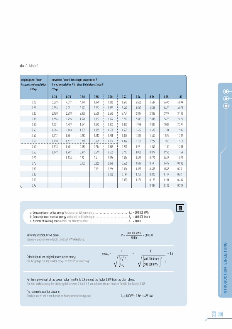
chart 1_Tabelle 1
a. Consumption of active energy Verbrauch an Wirkenergie: . . . . . . . . . . . . . . . . . . . . . . . . . . EW = 300 000 kWh b. Consumption of reactive energy Verbrauch an Blindenergie: . . . . . . . . . . . . . . . . . . . . . . . . EB = 400 000 kvarhc. Number of working hours Anzahl der Arbeitsstunden: . . . . . . . . . . . . . . . . . . . . . . . . . . . . . t = 600 h
Resulting average active power:Daraus ergibt sich eine durchschnittliche Wirkleistung:
Calculation of the original power factor cosϕ1:Der Ausgangsleistungsfaktor cosϕ1 errechnet sich wie folgt:
For the improvement of the power factor from 0.6 to 0.9 we read the factor 0.849 from the chart above.Für eine Verbesserung des Leistungsfaktors von 0.6 auf 0.9 entnehmen wir aus unserer Tabelle den Faktor 0.849.
The required capacitor power is:Damit erhalten wir einen Bedarf an Kondensatorleistung von: QC = 500kW · 0.849 = 425 kvar
P = = 500 kW300 000 kWh
600 h
cosϕ1 = = = 0.61
EB 2
EW( ) + 1400 000 kvarh 2
300 000 kWh( ) + 1
1
original power factor
Ausgangsleistungsfaktor
cosϕ1
conversion factor F for a target power factor F
Umrechnungsfaktor F für einen Zielleistungsfaktor F
cosϕ2
0.70 0.75 0.80 0.85 0.90 0.92 0.94 0.96 0.98 1.00
0.20 3.879 4.017 4.149 4.279 4.415 4.473 4.536 4.607 4.696 4.899
0.25 2.853 2.991 3.123 3.253 3.389 3.447 3.510 3.581 3.670 3.873
0.30 2.160 2.298 2.430 2.560 2.695 2.754 2.817 2.888 2.977 3.180
0.35 1.656 1.795 1.926 2.057 2.192 2.250 2.313 2.385 2.473 2.676
0.40 1.271 1.409 1.541 1.672 1.807 1.865 1.928 2.000 2.088 2.291
0.45 0.964 1.103 1.235 1.365 1.500 1.559 1.622 1.693 1.781 1.985
0.50 0.712 0.85 0.982 1.112 1.248 1.306 1.369 1.440 1.529 1.732
0.55 0.498 0.637 0.768 0.899 1.034 1.092 1.156 1.227 1.315 1.518
0.60 0.313 0.451 0.583 0.714 0.849 0.907 0.97 1.042 1.130 1.333
0.65 0.149 0.287 0.419 0.549 0.685 0.743 0.806 0.877 0.966 1.169
0.70 0.138 0.27 0.4 0.536 0.594 0.657 0.729 0.817 1.020
0.75 0.132 0.262 0.398 0.456 0.519 0.59 0.679 0.882
0.80 0.13 0.266 0.324 0.387 0.458 0.547 0.75
0.85 0.135 0.194 0.257 0.328 0.417 0.62
0.90 0.058 0.121 0.193 0.281 0.484
0.95 0.037 0.126 0.329

INTR
OD
UCT
ION
_EIN
LEIT
UN
G
10
Influence of Harmonics, Harmonic Filtering
Developments in modern semiconductor technology have led to a signifi-cant increase in the number of thyristor- and inverter-fed loads.
Unfortunately these non-linear loads have undesirable ef-fects on the incoming AC supply, drawing appreciable inductive reactive power and a non-sine-wave current. The supply system needs to be kept free of this harmonic distortion to prevent equipment malfunction.
A typical inverter current is composed of a mixture of si-newave currents; a fundamental component at the supply frequency and a number of harmonics whose frequencies are integer multiples of the line frequency (in three phase mains most of all the 5th, 7th, and 11th harmonic). The harmonics lead to a higher capacitor current, because the reactive resistance of a capacitor reduces with rising frequency.
The rising capacitor current can be accommodated by constructional improvements in the manufacture of the capacitor. Howe-ver a resonating circuit between the power factor correction capacitors, the inductance of the feeding transformer and the mains may occur. If the frequency of such a resonating circuit is close enough to a harmonic fre-quency, the resulting circuit amplifies the oscillation and leads to immense over-currents and over-voltages.
Harmonic distortion of an AC supply can result in any or all of the following:
• Premature failure of capacitors.
• Nuisance tripping of circuit breakers and other protective devices.
• Failure or maloperation of computers, motor drives, lighting circuits and other sensitive loads.
The installation of detuned (reactor-connected) capacitors is designed to force the resonant frequency of the network below the frequency of the lowest harmonic present, thereby ensuring no resonant circuit and, by implication, no amplification of harmonic currents. Such an installation also has a partial filtering effect, reducing the level of voltage distortion on the supply, and is recommended for all cases where the share of harmonic generating loads is more than 20% of the overall load to be compensated. The resonance frequency of a detuned capacitor is always below the frequency of the fifth harmonic.
A close-tuned filter circuit however is tuned to a certain harmonic frequency and presents a very low impedance to the individual harmonic current, diverting the majority of the current into the filter bank rather than the supply.
Einfluss von Oberwellen und deren Filterung
Die Entwicklung der modernen Halbleitertechnologien hat zu einer ent-scheidenden Erhöhung der Anzahl von thyristor- und konvertergesteuerten Verbrauchern geführt.
Leider üben Konverter unerwünschte Nebeneffekte auf das Wechselspannungsnetz aus, indem sie eine beachtliche induktive Blind-leistung und einen nichtsinusförmigen Strom verursachen. Diese Verunrei-nigung des Versorgungsnetzes kann zu Beschädigungen und Fehlfunktio-nen von Ausrüstungen und Geräten führen.
Ein typischer Konverterstrom ist aus einer Überlagerung von verschiedenen sinusförmigen Teilströmen zusammengesetzt, d.h. ei-ner Grundschwingung, welche die Frequenz des Netzes aufweist, und einer Anzahl von sogenannten Harmonischen oder Oberwellen, deren Frequenzen ein Vielfaches der Netzfrequenz betragen (in Dreiphasennetzen treten vor-wiegend die fünfte, siebente und elfte Oberwelle auf). Diese Oberwellen führen zu einem erhöhten Kondensatorstrom, da sich der Blindwiderstand eines Kondensators mit steigender Frequenz verringert.
Dem steigenden Kondensatorstrom kann man durch kon-struktive Verbesserungen des Kondensators begegnen, allerdings wird dadurch nicht das Risiko von Resonanzerscheinungen zwischen den Leis-tungskondensatoren auf der einen Seite sowie der Induktivität des ein-speisenden Transformators und des Netzes auf der anderen Seite beseitigt. Erweist sich nämlich die Resonanzfrequenz eines solchen Resonanzkreises nahe genug an der Frequenz einer der Oberwellen im Netz, so kann dieser Resonanzkreis die Schwingung der Oberwelle verstärken und zu immensen Überströmen und Überspannungen führen.
Die Oberwellenverunreinigung eines Wechselspannungsnetzes kann einige oder alle der nachstehenden Auswirkungen haben:
• frühzeitiges Ausfallen von Kondensatoren
• verfrühtes Ansprechen von Schutzschaltern und anderen Siche-rungseinrichtungen
• Ausfall oder Fehlfunktion von Computern, Antrieben, Beleuchtungs-einrichtungen und anderen empfindlichen Verbrauchern
Die Installation von verdrosselten Kondensatoren soll die Resonanzfrequenz des Netzes unter die Frequenz der niedrigsten vorhan-denen Oberwelle zwingen. Dadurch wird eine Resonanz zwischen den Kon-densatoren und dem Netz und damit auch eine Verstärkung von Oberwel-lenströmen verhindert. Eine solche Installation hat auch einen Filtereffekt, indem sie den Grad der Spannungsverzerrung im Netz verringert. Sie wird deshalb für alle Fälle empfohlen, in denen der Leistungsanteil der ober-wellenerzeugenden Verbraucher mehr als 20% der Gesamtleistung beträgt. Die Resonanzfrequenz eines verdrosselten Kondensators liegt immer un-terhalb der Frequenz der 5. Oberwelle.
Ein abgestimmter Filterkreis ist dagegen speziell auf eine bestimmte Oberwellenfrequenz abgestimmt und stellt für den jeweiligen Oberwellenstrom eine sehr niedrige Impedanz dar. Dadurch wird ein Groß-teil des Oberwellenstromes in den Filterkreis umgeleitet.

COMPARISON OF CONVENTIONAL MEDIUM VOLTAGE CAPACITORSAND ENGINEERING TECHNIQUES
MITTELSPANNUNGSKONDENSATOREN- UND ANLAGENTECHNIKEN IM VERGLEICH
ALL
FILM
VS.
MSD
11
This description and our product range both focus on single capacitors and reactive power compensation systems in the power range from 50 to approx. 6,000 kvar, because the greatest deficit in risk-awareness is present here. In practice, they are often just «parked» somewhere since the dimensions and prices of such equipment are relatively small and they should be close to the load. Protection devices are then often neglected in comparison to larger systems, because the costs appear to be unreasonably high.
It is a fact that the protection systems necessary for the reliable operation of a small reactive power compensation system, e.g. 300 kvar, require the same protection relay and a similarly expensive current transformer as a 10 MVAR system. If the total power is divided into 3 or 6 units, even higher costs are incurred. Disparities of up to 80% for the protection component then occur, compared to 5% for larger systems.
Serious mistakes are often made especially in the reactive power compensation of small installations, which lead to equipment dam-age and environmental incompatibility. This unsatisfactory situation was the starting point for the development of a new concept that offers an acceptable relationship between protection costs and total costs, while reducing the ecological risk.
Operational stress of Allfilm medium voltage capacitors
Capacitors operate at full power immediately after every switching. No-load or low-load periods do not exist. The design is made under economical constraints with high electrical field strengths up to 75 kV/mm and a finite service life, which can be dependent on many influencing factors, and is estimated from statistical data. There are many effects that cannot be detected during durability tests.
Summarising, it can be said that modern power capacitors are very reliable and failure rates greater than 0.2% per year are very rare. However, it must be considered that much higher failure rates occur from early failures, manufacturing faults, dimensioning errors, incorrect appli-cation or overload.
The effects of such failures must be assessed carefully by means of a risk analysis that also includes the ecological risk, due to the high short-circuit power present in medium voltage installations.
Objective of capacitor protection techniques
The reduction of damage to the environment is the most important criterion for capacitors, while preventive protection against permanent damage is the prime concern with motors, transformers, inverters, lines, cables and similar components.
Breakdown behaviour of Allfilm medium voltage capacitors
Breakdown of the dielectric is the prime cause of failure. Only this break-down and the resulting consequential effects are considered here.
Der Schwerpunkt dieser Ausführungen und unserer Produktpalette liegt bei Einzelkondensatoren und Blindleistungs-Kompensationsanlagen im Leistungsbereich von 50 bis ca. 6.000 kvar, weil hier die größten Defizite im Risikobewusstsein bestehen. Da Abmessungen und Preis solcher Anla-gen verhältnismäßig gering sind und der Einsatz möglichst verbrauchernah erfolgen soll, werden sie in der Praxis oft «irgendwo» hingestellt. Dabei werden häufig die Schutzeinrichtungen im Vergleich zu großen Anlagen vernachlässigt, weil die Kosten unangemessen hoch erscheinen.
In der Tat ist es so, dass die für einen sicheren Betrieb notwendige Schutztechnik für eine kleine Kompensationsleistung, von z.B. 300 kvar, dasselbe Schutzrelais und einen genauso teueren Wandler erfor-dert wie eine 10 Mvar Anlage. Bei Aufteilung der Gesamtleistung in 3 oder 6 Einheiten entstehen sogar noch höhere Kosten. Es ergeben sich dann Missverhältnisse von bis zu 80% Schutzkostenanteil bei Kleinanlagen gegenüber 5% bei großen Anlagen. Deshalb werden gerade bei der Blind-leistungs-Kompensation von kleineren Anlagen häufig schwerwiegende Fehler gemacht, die zu Sach- und Umweltschäden führen können. Diese unbefriedigende Situation war der Ausgangspunkt für die Entwicklung ei-nes neuen Konzeptes, das ein vertretbares Verhältnis von Schutzkosten zu Gesamtkosten erlaubt und das Umweltrisiko minimiert.
Betriebsbeanspruchungen von Allfilm – Mittelspannungskondensatoren
Kondensatoren sind bei jeder Zuschaltung sofort mit voller Leistung in Be-trieb. Leerlauf oder Schwachlastzeiten gibt es nicht. Aus wirtschaftlichen Gründen erfolgt die Auslegung mit einer hohen elektrischen Feldstärke von bis zu 75 kV/mm und eine endlichen Lebensdauer, die nach statistischen Kriterien von vielen Einflussfaktoren abhängig sein kann. Es gibt viele Be-einträchtigungen, die bei Lebensdauerprüfungen nicht erfassbar sind.
Zusammenfassend ist festzustellen, dass Leistungs-kon-densatoren heute sehr zuverlässig sind und Ausfallraten von > 0,2% pro Jahr nur selten erreicht werden.
Trotzdem ist nicht auszuschließen, dass sich auf Grund von Frühausfällen, Fertigungsfehlern, Dimensionierungs- bzw. Applikati-onsfehlern oder Überlastung gelegentlich weit höhere Ausfallraten erge-ben. Die möglichen Auswirkungen derartiger Ausfälle sind wegen der bei Mittelspannungsanlagen hohen Kurzschlussleistung sorgfältig durch eine Risikoanalyse, die auch das Umweltrisiko einschließt, zu bewerten.
Zielsetzung der Kondensatorschutztechnik
Während bei Motoren, Transformatoren, Stromrichtern, Leitungen, Kabeln und ähnlichen Komponenten ein vorbeugender Schutz der Betriebsmittel vor bleibenden Beschädigungen im Vordergrund steht, ist bei Kondensa-toren die Eingrenzung von Schadensauswirkungen auf die Umgebung wich-tigstes Kriterium.
Ausfallverhalten von Allfilm - Mittelspannungskondensatoren
Die Ausfallursache Nr. 1 sind Durchschläge im Dielektrikum. Aus diesem Grunde soll hier nur dieser Fehler und die daraus resultierenden Folgeaus-wirkungen betrachtet werden.

ALL
FILM
VS.
MSD
12
Every breakdown of a single winding element in a capaci-tor with several internal serial winding circuits leads to a change of the internal voltage distribution, irrespective of whether this winding is fused individually or whether it is a fuse-less design. This leads inevitably to higher voltage stress in the remaining winding elements. Accelerated ageing accompanies the increased voltage stress, which leads to further winding breakdowns.
Considerable damage to the environment of the capacitor must be expected if the breakdown process is uncontrolled, i.e. operation is continued until an over-current, earth or short-circuit trip responds.
This means that, when the maximum permitted energy input into the capacitor casing is exceeded (violation of the typical cur-rent-time destruction limit), it can, in the worst case, tear open, and the contents of the casing be ejected. A considerable shock wave, with ignition of the oil spray and the solid inflammable content, are conceivable further consequences.
! Protection for medium voltage capacitors normally means the mini-misation of effects of already existing, irreversible capacitor dam-age to the direct neighbourhood. This occurs in the knowledge that Allfilm capacitors contain a large proportion of ecologically critical, flammable, solid and fluid organic materials, which pose a consider-able hazard potential.
3-phase medium voltage capacitors
These capacitors are frequently built without internal fuses, due to their usually low power and three-phase design. Such a capacitor exhibits a group short-circuit after a winding breakdown.
Depending upon the number of internal serial circuits, the capacitance and voltage stress in the affected branch increase by the fac-tor n/n-1.
The current increases correspondingly. This is thermally barely noticeable due to the low capacitor losses and further short-circuits can occur, especially if the fault remains unnoticed for a long period.
! Since remaining windings can still survive at up to twice the nominal voltage for minutes or even hours, the effects on fuses and feeders under the influence of twice the rated current are to be taken into account.
Gas formation need not be expected during this overload phase, since the film layers weld together solidly at the breakdown position and can carry increased current for a long period. An internal pressure build-up does not occur during this period.
! Pressure monitors are ineffective in Allfilm medium voltage capacitors.
Jeder Durchschlag eines einzelnen Wickelelementes in ei-nem Kondensator mit mehreren internen Wickel-Serienschaltungen führt, unabhängig davon ob diese Wickel einzeln abgesichert sind oder ob es sich um eine sicherungslose Konstruktion handelt, zu einer Änderung der inter-nen Spannungsverteilung. Dies führt zwangsläufig beim verbleibenden Teil der Wickelelemente zu einer höheren Spannungsbelastung.
Mit der erhöhten Spannungsbelastung geht eine beschleu-nigte Alterung einher, die zwangsläufig weitere Wickelausfälle nach sich zieht. Bei unkontrolliertem Verlauf des Ausfallprozesses, das heißt wei-terer Betrieb bis zum Ansprechen einer vorgeschalteten Überstrom-, Erd- oder Kurzschlussauslösung, muss mit erheblichen Schadensauswirkungen auf die Umgebung des Kondensators gerechnet werden.
Das bedeutet, dass bei Überschreitung des maximal zu-lässigen Energieeintrages in ein Kondensatorgehäuse (Überschreitung der typischen Strom-Zeit-Zerstörungsgrenze), dieses im ungünstigsten Fall aufreißt und der Gehäuseinhalt hinausgeschleudert wird. Eine erhebliche Druckwelle, mit Entzündung der zerstäubten Ölfüllung und des festen brennbaren Inhaltes, sind die weiteren denkbaren Folgen.
! Schutztechnik bei Mittelspannungskondensatoren bedeutet in der Regel, die Minimierung der Auswirkungen eines bereits eingetrete-nen irreversiblen Kondensatorschadens auf die unmittelbare Um-gebung. Dies erfolgt im Bewusstsein, dass Allfilm-Kondensatoren einen großen Anteil umweltkritischer, brennbarer, fester und flüssi-ger organische Stoffe enthalten, die ein beachtliches Gefährdungs-potential darstellen.
3-phasige Mittelspannungskondensatoren
Wegen der meist nur kleinen Leistung und der 3-phasigen Bauart, werden diese Kondensatoren häufig ohne interne Sicherung gebaut. Ein solcher Kondensator weist nach einem Wickeldurchschlag einen Gruppenkurz-schluss auf. Je nach Anzahl der internen Serienschaltungen erhöhen sich die Kapazität und Spannungsbelastung im betroffenen Strang um den Faktor n/n-1.
Dementsprechend steigt die Stromaufnahme. Wegen der niedrigen Kondensatorverluste macht sich das normalerweise thermisch kaum bemerkbar und es kann zu weiteren Gruppenkurzschlüssen kommen, besonders wenn der Fehler lange Zeit unbemerkt bleibt.
! Da hierbei Restwickel bei bis zur 2-fachen Nennspannung noch eine Überlebenszeit von Minuten und sogar Stunden haben können, sind die Auswirkungen auf Sicherungen und Zuleitungen unter dem Ein-fluss des bis zu 2-fachen Nennstroms zu beachten.
Während dieser Überlastphase ist nicht mit einer Gasbildung zu rechnen, da die Belagfolien am Durchschlagsort massiv miteinander verschweißen und langfristig erhöhte Ströme führen können. Somit kommt es auch wäh-rend dieses Zeitraumes nicht zu einem Innen-Druckanstieg.
! Gehäusedrucküberwachungen in Allfilm-Mittelspannungskonden-satoren sind wirkungslos.

RISKS AND SHORTCOMINGS OF FORMER COMMON CONCEPTSRISIKEN UND UNZULÄNGLICHKEITEN
DER BISHER GEBRÄUCHLICHEN KONZEPTE
ALL
FILM
VS.
MSD
13
Various concepts for the protection and switching of medium voltage ca-pacitors are known from practice. The five most usual will be discussed here.
Problem:Current overload caused by a group short-circuit in the capacitor, or also at resonance with network harmonics, cause a danger that the short-circuit protection fuse trips in the over-current range if the current rating is too low. The arc quenching capability of the fuses can be overtaxed due to the capacitive load. Reverse sparking occurs with very high intensities and ultimately leads to an open arc at the fuse contacts, and to a phase short-circuit at the installation position of the fuse.
Choice of nominal fuse current
Fuses must be chosen for at least 1.6 times the rated capacitor current to withstand the switching current. Since Allfilm capacitors can remain connected to the mains in fault situations (failure of serial groups) for a long period with up to double the nominal capacity, fuses should be rated for at least 2 × I
N. The risk that fuses rupture due to over-current, but do
not quench the arcing is avoided by this method.If fuse ratings of approx. 200 A are exceeded, then an ad-
ditional problem occurs: In the case of a short-circuit, the fuse throughput energy becomes greater than the energy absorption capacity of the capaci-tor enclosure.
Aus der Praxis sind verschiedene Konzepte zum Schutz und zum Schalten von Mittelspannungskondensatoren bekannt. Die 5 gebräuchlichsten sol-len hier behandelt werden.
Problem:Bei Stromüberlast durch einen Gruppenkurzschluss im Kondensator oder auch bei Resonanzen mit Netzharmonischen besteht die Gefahr, dass die Kurzschlussschutzsicherung bei zu geringem Nennstrom im Über-strombereich zur Auslösung kommt. Wegen der kapazitiven Last ist das Löschvermögen der Sicherungen überfordert. Es kommt zu Rückzündungen mit sehr hohen Werten und letztendlich zum offenen Lichtbogen an den Sicherungskontaktstellen und zum Phasenkurzschluss am Einbauort der Sicherungen.
Wahl des Sicherungsnennstromes
Zur Führung des Einschaltstromes sind Sicherungen mindestens für den 1,6-fachen Kondensatornennstrom auszulegen. Da Allfilm-Kondensatoren im Fehlerfall (Ausfall von Seriengruppen) noch lange mit bis zu doppelter Nennkapazität am Netz bleiben können, sollten Sicherungen mindestens für 2 × I
N ausgelegt werden. Das Risiko, dass Sicherungen wegen Über-
strom auslösen aber nicht löschen wird dadurch vermieden.Werden bei der Auswahl des Sicherungsnennstromes Werte
von ca. 200A überschritten, tritt ein zusätzliches Problem auf: Im Kurz-schlussfall wird die Durchlassenergie der Sicherung größer als die Ener-gieaufnahmefähigkeit des Kondensatorgehäuses.
Variant 1Variante 1
A low-power compensation system is switched with a vacuum contactor and additional h.v HRC. fuses are employed as short-circuit protection for switchgear, busbars and lines.
Eine Kompensationsanlage kleiner Leistung wird mit einem Vakuumschütz geschaltet, als Kurzschlussschutz für Schaltgeräte, Sammelschienen und Leitungen werden zusätzlich HH-Sicherungen eingesetzt.
L1-3
F1-3
K1
C1

ALL
FILM
VS.
MSD
14
Selection of the rated voltage for capacitor fuses
Current limiting fuses have an excellent interruption behaviour during short-circuits, but are usually not able to interrupt capacitive currents at overload. A peak voltage with twice the amplitude occurs at the gap due to the charged capacity, which can result in arcing-back with even higher voltages. One should therefore always employ h.v. h.b.c. general purpose fuses with the next higher nominal voltage than the actual mains voltage.
Problem:If a protection system for early fault detection, such as asymmetry protec-tion or phase current comparison protection is not employed additionally, then the concept is unsafe.
! As a rule, circuit breakers are unsuitable for the disconnection of capacitors with an internal short-circuit, since they do not possess a current-limiting interruption characteristic. The throughput ener-gy before isolation is always much larger than a capacitor enclosure can withstand.
Wahl der Nennspannung von Kondensatorsicherungen
Strombegrenzende Sicherungen haben zwar ein ausgezeichnetes Abschalt-verhalten bei Kurzschlüssen, sind aber meist nicht in der Lage, kapazitive Ströme bei Überlast abzuschalten. Wegen der geladenen Kapazität tritt an der Trennstelle die 2-fache Scheitelspannung auf, was zu Rückzündun-gen mit noch weit höheren Spannungen führen kann. Man sollte deshalb grundsätzlich nur HH-Vollbereichssicherungen mit der nächsthöheren Nennspannung als die aktuelle Netzspannung verwenden.
Problem:Wenn kein Schutzsystem zur Fehlerfrüherkennung wie Unsymmetrieschutz oder ein Phasenstromvergleichsschutz zusätzlich eingesetzt wird, ist das Konzept unsicher.
! Leistungsschalter sind grundsätzlich nicht geeignet, Kondensa-toren bei einem inneren Kurzschluss sicher abzuschalten, weil sie keine strombegrenzende Abschaltcharakteristik besitzen. Die Durchlassenergie bis zur Trennung ist in jedem Fall weit höher als ein Kondensatorgehäuse vertragen kann.
Variant 2Variante 2
A low-power compensation system with several switching stages, in-rush current limiting reactors, and vacuum contactors as step switches and circuit-breakers as short-circuit protection.
Eine Kompensationsanlage kleiner Leistung mit mehreren Schaltstufen, Einschaltstrombegrenzungsdrosseln, Vakuumschützen als Stufenschalter und Leistungsschalter als Kurzschlussschutz.
L1
K1
C1
L2
K2
C2
F 1-3 F 4-6Q1
I >
ALL
FILM
VS.
MSD
15
Variant 3Variante 3
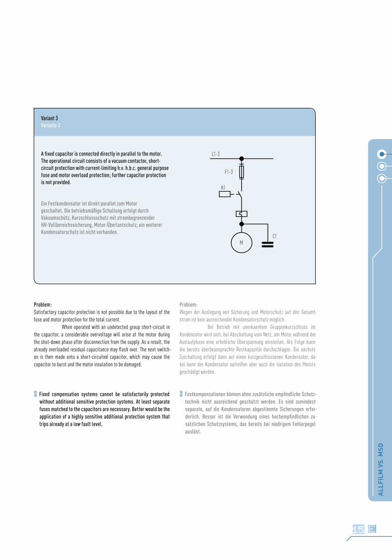
A fixed capacitor is connected directly in parallel to the motor. The operational circuit consists of a vacuum contactor, short-circuit protection with current-limiting h.v. h.b.c. general purpose fuse and motor overload protection; further capacitor protection is not provided.
Ein Festkondensator ist direkt parallel zum Motor geschaltet. Die betriebsmäßige Schaltung erfolgt durch Vakuumschütz, Kurzschlussschutz mit strombegrenzender HH-Vollbereichssicherung, Motor-Überlastschutz, ein weiterer Kondensatorschutz ist nicht vorhanden.
M
F1-3
K1
C1
L1-3
Problem:Satisfactory capacitor protection is not possible due to the layout of the fuse and motor protection for the total current.
When operated with an undetected group short-circuit in the capacitor, a considerable overvoltage will arise at the motor during the shut-down phase after disconnection from the supply. As a result, the already overloaded residual capacitance may flash over. The next switch-on is then made onto a short-circuited capacitor, which may cause the capacitor to burst and the motor insulation to be damaged.
! Fixed compensation systems cannot be satisfactorily protected without additional sensitive protection systems. At least separate fuses matched to the capacitors are necessary. Better would be the application of a highly sensitive additional protection system that trips already at a low fault level.
Problem:Wegen der Auslegung von Sicherung und Motorschutz auf den Gesamt-strom ist kein ausreichender Kondensatorschutz möglich.
Bei Betrieb mit unerkanntem Gruppenkurzschluss im Kondensator wird sich, bei Abschaltung vom Netz, am Motor während der Auslaufphase eine erhebliche Überspannung einstellen. Als Folge kann die bereits überbeanspruchte Restkapazität durchschlagen. Die nächste Zuschaltung erfolgt dann auf einen kurzgeschlossenen Kondensator, da-bei kann der Kondensator aufreißen aber auch die Isolation des Motors geschädigt werden.
! Festkompensationen können ohne zusätzliche empfindliche Schutz-technik nicht ausreichend geschützt werden. Es sind zumindest separate, auf die Kondensatoren abgestimmte Sicherungen erfor-derlich. Besser ist die Verwendung eines hochempfindlichen zu-sätzlichen Schutzsystems, das bereits bei niedrigem Fehlerpegel auslöst.

ALL
FILM
VS.
MSD
16
Variant 4Variante 4
A capacitor with switchgear and asymmetry protection, additional circuit breaker or load switch with current-limiting fuses for short-circuit protection.
Ein Kondensator mit Schaltgerät und Unsymmetrieschutz, zusätzlich Leistungsschalter oder Lastschaltgerät mit strombegrenzenden Sicherungen zum Kurzschlussschutz.USS
K1
F1-3
C1 C2 C3 C4 C4 C5
L1L2L3
Problem:Load unbalance protection circuits detect the circulating current in the neutral branch of a bridge circuit or between two star points of a double circuit, that occurs after a breakdown of a winding or a winding group.
Even the breakdown of the first winding element in small capacitor systems can be detected reliably and be used to trip the associated switch. The other switching functions of this switch are irrelevant, so far as the protection tripping disconnects the capacitor immediately at a low fault level, or in the case of multi-step systems, after a previous alarm signal.
Reliable protection against consequential damage is achieved with the correct setting of a predefined switch-off threshold at a low fault level.
! Remaining problem: High costs and effort for ecological protection and disposal.
Problem:Unsymmetrieschutzschaltungen erfassen den im Nullzweig einer Brückenschaltung oder zwischen zwei Sternpunkten einer Doppelschaltung auftretenden Ausgleichsstrom, der bei Durchschlag eines Wickels oder einer Wickelgruppe auftritt.
Bereits der Durchschlag des ersten Wickelelementes kann bei kleinen Kondensatorenanlagen zuverlässig erkannt und zur Auslösung des vorgelagerten Schaltgerätes verwendet werden. Dabei ist es unerheblich, welche sonstigen Schaltfunktionen dieses Schaltgerät noch zu erfüllen hat, sofern die Schutzauslösung sofort, oder bei mehrstufigen Systemen nach einer vorausgegangenen Warnmeldung, den Kondensator bei noch niedrigem Fehlerpegel abschaltet.
Bei richtiger Einstellung einer vordefinierten Abschaltschwelle auf niedrigem Fehlerpegel wird ein zuverlässiger Schutz gegen Folgeschäden erzielt.
! Restproblem: Hohe Kosten und großer Aufwand für Umweltschutz und Entsorgung.

ALL
FILM
VS.
MSD
17
Variant 5Variante 5
A capacitor with switchgear and phase-current comparison protection, additional circuit breaker or load switch with current-limiting fuses for short-circuit protection.
Ein Kondensator mit Schaltgerät und mit Phasenstrom-Vergleichs-schutz, zusätzlich Leistungsschalter oder Lastschaltgerät mit strombegrenzenden Sicherungen zum Kurzschlussschutz.
IDK1
F1-3
C1 C2 C3
L1-3
Problem:Similar to an asymmetry protection scheme; can avoid consequential damage from premature tripping. Network asymmetries or starting asym-metries can lead to erroneous tripping more easily than with variant 4. The sensitivity which may be achieved with phase comparison protection is lower than with an asymmetry protection circuit.
Apart from that, the problems of variant 4 remain.
Course of damage at capacitors with winding fuses
Depending on type, winding fuses are able to interrupt currents at network frequency, with current limitation at mains voltages up to several kV. At higher voltages and with several internal series connections, the voltage at the remaining windings continues to increase with decreasing number of paralleled winding elements, until the disconnection ability of the winding fuse is overtaxed. The damage arising here can lead to the destruction of the insulation between the phases or towards the enclosure.
The consequences are depending on the through-put energy of the associated over-current protection and more or less identical to those occurring at capacitors without fuses. Capacitors can be considered partially safe if they contain no more than two internally fused, series-connected winding groups between the phases, e.g. star-connected 3.6 kV capacitors or single-phase capacitors up to 3.6 kV in furnace systems.
Problem:Ähnlich wie mit einem Unsymmetrieschutz, kann eine frühzeitige Auslösung Folgeschäden vermeiden. Netzunsymmetrien oder Anfangsunsymmetrien können leichter zu Fehlauslösungen als bei Variante 4 führen. Darüber hi-naus ist die erzielbare Empfindlichkeit mit einem Phasenvergleichsschutz geringer als bei einer Unsymmetrie-Schutzschaltung.
Sonst gleiches Restproblem wie Variante 4.
Schadensverlauf bei Kondensatoren mit Wickelsicherungen
Wickelsicherungen können, je nach Bauart, bis zu einigen kV Netzspannung auch netzfrequente Kurzschlussströme strombegrenzend abschalten. Bei höherer Nennspannung und mehreren internen Serienschaltungen steigt mit abnehmender Zahl paralleler Wickel an den verbleibenden Wickeln die Spannung immer weiter an, bis die Trennfähigkeit der Wickelsicherung überfordert ist. Die dabei auftretenden Schäden können zur Zerstörung der Isolation zum Gehäuse oder zwischen den Phasen führen.
Die daraus resultierenden Auswirkungen sind abhängig von der Durchlassenergie des vorgelagerten Überstromschutzes und ansonsten weitestgehend identisch mit denen bei sicherungslosen Kondensatoren.
Als teilweise eigensicher können Kondensatoren gelten, die maximal 2 intern abgesicherte Wickelgruppen in Reihenschaltung zwi-schen den Phasen aufweisen, z.B. 3,6kV Kondensatoren in Sternschaltung oder Einphasenkondensatoren bis etwa zu 3,6 kV in Ofenanlagen.

ALL
FILM
VS.
MSD
18
During the development of a highly advanced state of fault, the risk rises that not only winding breakdowns occur, but parts of the internal insulation get damaged, which may lead to a short-circuit at a high fault level. The risk of consequential damage is significantly higher than if asymmetry protection systems were used.
Basic rule
The most important criterion for a timely disconnection without consequential damage is early detection and, if possible, rapid dis-connection of capacitor groups after the failure of windings or winding groups. This ensures that fuses do not trip due to increased current and that rapid short-circuit trips do not occur, both of which can have the very serious consequences described above. This applies especially to three-phase capacitors.
Other criteria must be taken into account in the case of large compensation powers, which shall not be discussed here. A network short-circuit is improbable due to multiple external series circuits.
Correct handling of fault tripping
One repeatedly observes that fault trips are reset or reclose attempts made by operating staff, without the cause of the trip being clarified and cleared. Enormous consequential damage is observed and documented from such incorrect conduct.
Im Verlauf eines weit fortgeschrittenen Ausfallzustandes erhöht sich aber das Risiko, dass nicht nur Wickeldurchschläge auftreten, sondern auch hier Teile der Isolation zwischen den Phasen oder zum Gehäu-se beschädigt werden, was dann zum Kurzschluss mit hohem Fehlerpegel führt. Das Risiko von Folgeschäden ist wesentlich höher als bei Anwen-dung von Unsymmetrie-Schutzschaltungen.
Grundregel
Wichtigstes Kriterium für eine rechtzeitige Trennung ohne Folgeschäden ist die Früherkennung und möglichst unverzögerte Abschaltung von Kon-densatoren beim Ausfall von Wickeln oder Wickelgruppen. Dadurch wird verhindert, dass weder Sicherungen durch erhöhten Strom thermisch auslösen, noch Kurzschlussschnellauslösungen auftreten können, die wie oben beschrieben, sehr schwerwiegende Folgen haben können. Dies gilt besonders für 3-phasige Kondensatoren.
Bei großen Kompensationsleistungen, die hier nicht behan-delt werden sollen, sind andere Kriterien zu beachten. Durch mehrfache äußere Serienschaltungen ist ein Netzkurzschluss unwahrscheinlich.
Richtiger Umgang mit Schutzauslösungen
Es wird immer wieder festgestellt, dass vom Betriebspersonal Schutzauslösungen zurückgestellt werden und Wiederzuschaltversuche erfolgen, ohne dass vorher die Auslöseursache geklärt und beseitigt wurde. Aus derartigem Fehlverhalten sind enorme Folgeschäden bekannt.

MSD – SELF-HEALING MEDIUM VOLTAGE CAPACITORSIN DRY TECHNOLOGY
MSD – SELBSTHEILENDE MITTELSPANNUNGSKONDENSATORENIN TROCKENTECHNOLOGIE
ALL
FILM
VS.
MSD
19
Our MSD capacitors are filled with solid materials, i.e. dry, instead of combustible liquid as with Allfilm medium voltage capacitors.
High-quality insulation between the active elements and the enclosure is achieved using a special process, which is designed and tested to suit the requirements for the nominal insulation voltage of the capacitor. This special insulation is of crucial importance for the safe operation of the internal pressure monitor: self-healing capacitors are not (yet) covered by current standards for medium voltage capacitors, such as IEC 60871, however, our MSD series fulfils all electrical and safety requirements of these standards. It has to be noted that the MSD capacitors – like any self healing capacitor – do not produce short circuits and can therefore not be disconnected from the system by internal or external blow-out fuses. This task is performed by integrated over-pressure switches as described in the standards applicable to capacitors for power electronics and for inductive heating. (VDE-EN 61071 and VDE-EN 60110)
Design and characteristicsAufbau und Eigenschaften
The MSD technology is based on the logical development of proven self-healing technology for low-voltage power cap. It also permits the eco-nomic manufacture of medium voltage capacitors without employing in-flammable and environmentally critical fluid oil fillings. The actual active capacitor element consists of a large number of high-quality, self-healing round MKP elements, which are wired to each other and installed in a stainless steel enclosure.
Die MSD-Technik basiert auf der konsequenten Weiterentwicklung der be-währten Technologie von selbstheilenden Niederspannungs-Leistungskon-densatoren. Sie gestattet es, nun auch Mittelspannungskondensatoren ohne brennbare und umweltkritische flüssige Ölfüllung wirtschaftlich herzustellen. Der eigentliche Aktivteil des Kondensators besteht aus einer größeren Zahl hochwertiger, selbstheilender MKP-Rundwickel, die, mitein-ander verschaltet, als Paket in ein Edelstahlgehäuse eingebaut werden.
Statt mit brennbarer Flüssigkeit wie bei Allfilm-Mittelspannungskon-densatoren sind unsere MSD-Kondensatoren mit Feststoffen gefüllt, also trocken.
Durch ein spezielles Verfahren wird eine qualitativ hoch-wertige Isolation zwischen Aktivteil und Gehäuse erreicht, die entspre-chend den Anforderungen der Nennisolationsspannung des Kondensators ausgelegt und geprüft ist. Diese spezielle Isolation ist für die sichere Funktion der Innendrucküberwachung von ausschlaggebender Bedeutung: obwohl selbstheilende Kondensatoren von den derzeit gültigen Standards für Mittelspannungskondensatoren, wie z.B. IEC 60871, (noch) nicht er-fasst werden, erfüllt unsere MSD-Serie alle elektrischen und sicherheits-technischen Anforderungen dieser Standards. Es ist jedoch zu beachten, dass die MSD-Kondensatoren – wie alle selbstheilenden Kondensatoren
– im Fehlerfall keine Kurzschlüsse erzeugen und somit nicht durch interne oder externe Schmelzsicherungen vom Netz getrennt werden können. Diese Aufgabe übernimmt ein integrierter Überdruckschalter wie in den Normen für Kondensatoren der Leistungselektronik und für induktive Erwärmung beschrieben. (VDE-EN 61071 sowie VDE-EN 60110)
Increasing safety awareness resulting from stricter product li-ability, the unsatisfactory situation with fusible links and the high costs for asymmetry protection or phase comparison protection have motivated us to seek a safe, simple and economic solution which will be described on the following pages: MSD – the ecologi-cally sound, self-healing medium voltage capacitor.
Das zunehmende Sicherheitsbewusstsein als Folge verschärfter Produkthaftung, die unbefriedigende Situation mit Schmelzsiche-rungen sowie die hohen Kosten für Unsymmetrieschutz oder Pha-senstromvergleich haben uns veranlasst, eine sichere, einfache und preisgünstige Lösung zu suchen, die auf den folgenden Seiten vorgestellt wird: MSD – der umweltfreundliche, selbstheilende Mittelspannungskondensator.
Wickelkörper winding element
Polypropylenfolie unmetallisiertpolypropylene film, uncoated
Stirnkontaktschicht contact layer
Polypropylenfolie, einseitig metallisiertpolypropylene film, metal deposit on one side
P
ALL
FILM
VS.
MSD
20
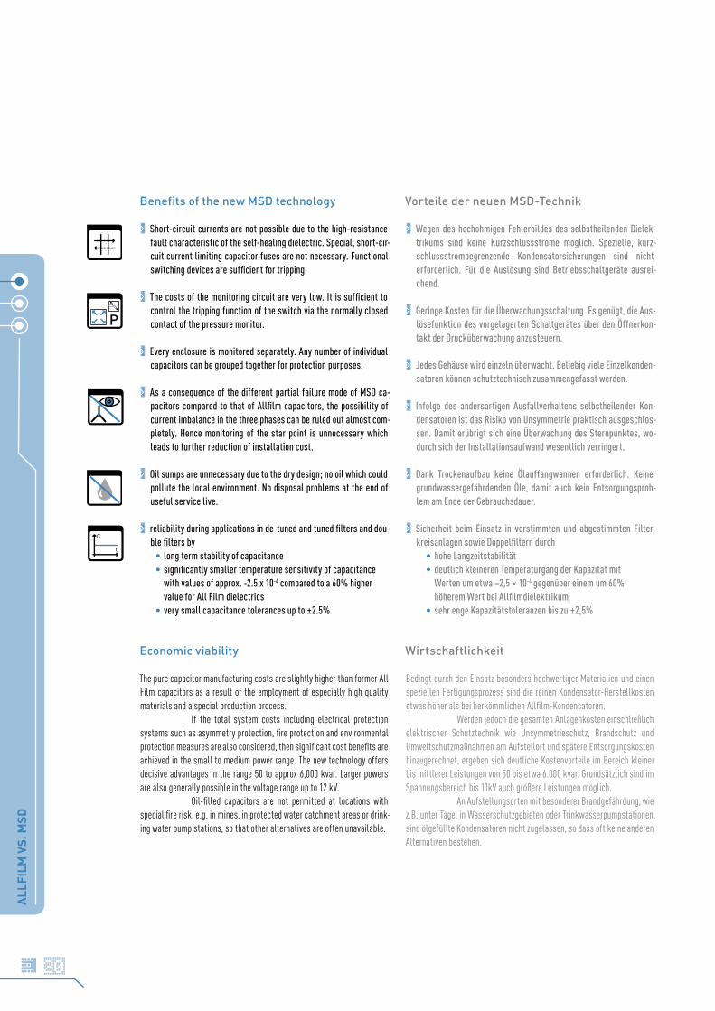
Benefits of the new MSD technology
> Short-circuit currents are not possible due to the high-resistance fault characteristic of the self-healing dielectric. Special, short-cir-cuit current limiting capacitor fuses are not necessary. Functional switching devices are sufficient for tripping.
> The costs of the monitoring circuit are very low. It is sufficient to control the tripping function of the switch via the normally closed contact of the pressure monitor.
> Every enclosure is monitored separately. Any number of individual capacitors can be grouped together for protection purposes.
> As a consequence of the different partial failure mode of MSD ca-pacitors compared to that of Allfilm capacitors, the possibility of current imbalance in the three phases can be ruled out almost com-pletely. Hence monitoring of the star point is unnecessary which leads to further reduction of installation cost.
> Oil sumps are unnecessary due to the dry design; no oil which could pollute the local environment. No disposal problems at the end of useful service live.
> reliability during applications in de-tuned and tuned filters and dou-ble filters by
• long term stability of capacitance• significantly smaller temperature sensitivity of capacitance with values of approx. -2.5 x 10⁻⁴ compared to a 60% higher value for All Film dielectrics • very small capacitance tolerances up to ±2.5%
Economic viability
The pure capacitor manufacturing costs are slightly higher than former All Film capacitors as a result of the employment of especially high quality materials and a special production process.
If the total system costs including electrical protection systems such as asymmetry protection, fire protection and environmental protection measures are also considered, then significant cost benefits are achieved in the small to medium power range. The new technology offers decisive advantages in the range 50 to approx 6,000 kvar. Larger powers are also generally possible in the voltage range up to 12 kV.
Oil-filled capacitors are not permitted at locations with special fire risk, e.g. in mines, in protected water catchment areas or drink-ing water pump stations, so that other alternatives are often unavailable.
Vorteile der neuen MSD-Technik
> Wegen des hochohmigen Fehlerbildes des selbstheilenden Dielek-trikums sind keine Kurzschlussströme möglich. Spezielle, kurz-schlussstrombegrenzende Kondensatorsicherungen sind nicht erforderlich. Für die Auslösung sind Betriebsschaltgeräte ausrei-chend.
> Geringe Kosten für die Überwachungsschaltung. Es genügt, die Aus-lösefunktion des vorgelagerten Schaltgerätes über den Öffnerkon-takt der Drucküberwachung anzusteuern.
> Jedes Gehäuse wird einzeln überwacht. Beliebig viele Einzelkonden-satoren können schutztechnisch zusammengefasst werden.
> Infolge des andersartigen Ausfallverhaltens selbstheilender Kon-densatoren ist das Risiko von Unsymmetrie praktisch ausgeschlos-sen. Damit erübrigt sich eine Überwachung des Sternpunktes, wo-durch sich der Installationsaufwand wesentlich verringert.
> Dank Trockenaufbau keine Ölauffangwannen erforderlich. Keine grundwassergefährdenden Öle, damit auch kein Entsorgungsprob-lem am Ende der Gebrauchsdauer.
> Sicherheit beim Einsatz in verstimmten und abgestimmten Filter-kreisanlagen sowie Doppelfiltern durch • hohe Langzeitstabilität • deutlich kleineren Temperaturgang der Kapazität mit
Werten um etwa –2,5 × 10⁻⁴ gegenüber einem um 60% höherem Wert bei Allfilmdielektrikum
• sehr enge Kapazitätstoleranzen bis zu ±2,5%
Wirtschaftlichkeit
Bedingt durch den Einsatz besonders hochwertiger Materialien und einen speziellen Fertigungsprozess sind die reinen Kondensator-Herstellkosten etwas höher als bei herkömmlichen Allfilm-Kondensatoren.
Werden jedoch die gesamten Anlagenkosten einschließlich elektrischer Schutztechnik wie Unsymmetrieschutz, Brandschutz und Umweltschutzmaßnahmen am Aufstellort und spätere Entsorgungskosten hinzugerechnet, ergeben sich deutliche Kostenvorteile im Bereich kleiner bis mittlerer Leistungen von 50 bis etwa 6.000 kvar. Grundsätzlich sind im Spannungsbereich bis 11kV auch größere Leistungen möglich.
An Aufstellungsorten mit besonderer Brandgefährdung, wie z.B. unter Tage, in Wasserschutzgebieten oder Trinkwasserpumpstationen, sind ölgefüllte Kondensatoren nicht zugelassen, so dass oft keine anderen Alternativen bestehen.
P
C
t
ALL
FILM
VS.
MSD
21
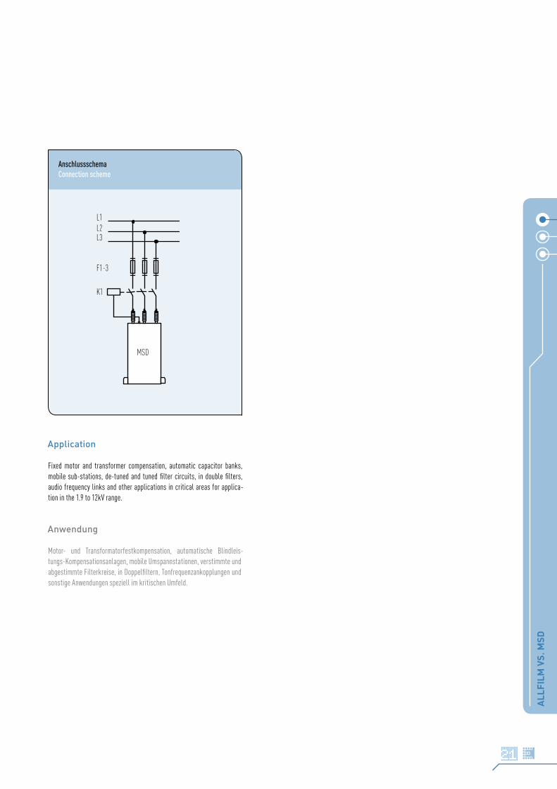
AnschlussschemaConnection scheme
Application
Fixed motor and transformer compensation, automatic capacitor banks, mobile sub-stations, de-tuned and tuned filter circuits, in double filters, audio frequency links and other applications in critical areas for applica-tion in the 1.9 to 12kV range.
Anwendung
Motor- und Transformatorfestkompensation, automatische Blindleis-tungs-Kompensationsanlagen, mobile Umspannstationen, verstimmte und abgestimmte Filterkreise, in Doppelfiltern, Tonfrequenzankopplungen und sonstige Anwendungen speziell im kritischen Umfeld.
L1L2L3
K1
F1-3
MSD

DEFINITIONS AND SELECTION CRITERIABEGRIFFE UND AUSWAHLKRITERIEN
DEF
INIT
ION
S_B
EGR
IFFE
22
Rated Voltage UN
Root mean square of the max. permissible value of sinusoidal AC voltage in continuous operation. Usually the rated mains voltage plus 5% overvoltage.
The rated voltage of the capacitors indicated in the data charts must not be exceeded even in cases of malfunction. Bear in mind that capacitors in detuned equipment are exposed to a higher voltage than that of the rated mains voltage; this is caused by the connection of detuning reactor and capacitor in series. Consequently, capacitors used with reactors must have a voltage rating higher than that of the regular mains voltage.
The voltage at a detuned capacitor’s terminals can be calculated as follows:
Test Voltage Between Terminals UBB
Routine test of all capacitors conducted at room temperature, prior to de-livery. A further test with 80% of the test voltage stated in the data sheet may be carried out once at the user’s location.
Insulation Level (BIL)
The first value describes the routine test of all capacitors between short-circuited terminals and case, conducted at room temperature. May be re-peated at the user’s location.
The second value refers to the lightning withstand voltage, tested in a special type test.
Rated Power QC
Reactive power resulting from the ratings of capacitance, frequency, and voltage.
Current Rating IN
RMS value of the current at rated voltage and frequency, excluding harmonic distortion, switching transients, and capacitance tolerance.
Nennspannung UN
Maximal zulässiger Effektivwert von sinusförmiger Wechselspannung im Dauerbetrieb. Entspricht i. d. R. der Netznennspannung zuzüglich 5% Spannungsüberhöhung.
Die Nennspannung der in den Datentabellen aufgeführten Kondensatoren darf – auch im Falle von Fehlfunktionen – nicht überschritten werden. Es muss auch beachtet werden, dass Kondensatoren in verdrosselten Anlagen aufgrund der Serienschaltung von Drossel und Kondensator einer höheren Spannung als der Netznennspannung ausgesetzt sind. Dementsprechend ist für verdrosselte Kondensatoren eine höhere Nennspannung zu wählen.
Die im Falle einer Verdrosselung am Kondensator anliegende Spannung lässt sich wie folgt ermitteln:
Prüfspannung Belag/Belag UBB
Prüfspannung, mit der alle Kondensatoren als Stückprüfung zwischen den Anschlüssen vor der Auslieferung geprüft werden. Beim Anwender ist eine Wiederholung dieser Prüfung mit dem 0,8fachen Wert der Prüfspannung zulässig.
Isolationsspannung (BIL)
Der erste Wert beschreibt die Prüfspannung, mit der alle Kondensato-ren zwischen den kurzgeschlossenen Anschlüssen und dem Gehäuse als Stückprüfung vor der Auslieferung geprüft werden. Beim Anwender ist eine Wiederholung dieser Prüfung zulässig.
Der zweite Wert beschreibt die im Rahmen einer Typprüfung geprüfte Blitzspannung.
Nennleistung QC
Blindleistung, die sich aus den Nennwerten von Kapazität, Frequenz und Spannung ergibt.
Nennstrom IN
Effektivwert des Stroms bei Betrieb unter Nennspannung und -frequenz, ohne Berücksichtigung von Oberwellenanteilen oder Schaltspitzen, und Kapazitätstoleranzen.
UNetz
= Mains voltage Netzspannung
UC = Capacitor voltage Kondensatorspannung
p = Detuning factor Verdrosselungsgrad
UC =UNetz
1 –p
100%( )
DEF
INIT
ION
S_B
EGR
IFFE
23
Maximum RMS Current Rating Imax
Maximum rms value of permissible current in continuous operation. All capacitors are rated 1.5 × IN, allowing for the current rise from permissible voltage and capacitance tolerances as well as harmonic distortion. Higher rms values than stated in the data charts require adjustments in construc-tion and are available on request.
! Continuous currents that exceed these values will lead to a build-up of heat in the capacitor and – as a result – reduced lifetime or premature failure. Permanent excess current may even result in failure of the capacitor’s safety mechanisms, i.e. bursting or fire (see pg. 27).
Care must be taken not to exceed the maximum voltage and current rat-ings when installing capacitors in close-tuned or detuned equipment (see data sheets for maximum ratings). The thermal monitoring of reactors, or the use of overcurrent protection relays in the capacitor circuit is recom-mended to protect against overloads.
Pulse Current Strength IS
Depending on construction and voltage rating, the design of our capacitors permits short term inrush currents of 100…400 × IN as standard. However, when switching capacitors in automatic capacitor banks without detuning reactors, higher loads are very often the case. This may have a negative effect on the operational life, especially of capacitors which are frequently connected and disconnected (e.g. primary stages).
! We therefore strongly recommend the use of adequate devices for limitation of the peak inrush currents.
Temperature Category
The average useful life of a capacitor depends very much on the ambient temperatures it is operated at.
The permissible operating temperatures are defined by the temperature class stated on label which contains the lower limit temperature (-40°C for all ELECTRONICON power capacitors) and a letter, which describes the values of the upper limit temperatures. The chart on page 24 details the maximum permitted ambient temperatures for capacitors for each temperature category acc. to IEC 60871.
Maximal zulässiger Effektivstrom Imax
Maximaler Effektivwert des im Dauerbetrieb zulässigen Stromes. Dieser Wert beträgt für alle Kondensatoren 1.5 × IN und beinhaltet die Stromü-berhöhungen, welche sich aus zulässigen Spannungs- und Kapazitätstole-ranzen sowie Oberwellenanteilen ergeben. Höhere Werte sind auf Anfrage durch konstruktive Maßnahmen realisierbar.
! Eine permanente Überschreitung dieser Werte führt zu einer er-höhten Eigenerwärmung des Kondensators und in der Folge zu ei-ner verringerten Lebensdauer oder zum Ausfall des Kondensators. Eine dauerhafte starke Überlastung kann sogar zum Versagen der Sicherheitsmechanismen des Kondensators führen. (siehe S. 27)
Es muss darauf geachtet werden, dass die maximalen Nennwerte von Strom und Spannung nicht überschritten werden, wenn Kondensatoren in verstimmten oder abgestimmten Filterkreisen installiert werden (Ma-ximalwerte s. Datentabellen). Wir empfehlen die Wärmeüberwachung der Drosseln oder die Benutzung von Überstromschutzrelais zum Schutz vor Überbelastungen.
Stoßstromfestigkeit IS
Je nach Bauform und Nennspannung sind unsere Kondensatoren für kurzzeitige Einschaltspitzenströme zwischen 100…400 × IN geeignet. Es muss beachtet werden, dass oft höhere Belastungen auftreten, wenn Kondensatoren in unverdrosselten, geregelten Kompensationsanlagen geschaltet werden. Dies kann einen negativen Effekt auf die Einsatzdauer besonders jener Kondensatoren haben, die häufig zu- und abgeschaltet werden (z.B. erste Stufe).
! Wir empfehlen dringend den Einsatz geeigneter Vorrichtungen zur Dämpfung der Einschaltspitzen.
Temperaturklasse
Die mittlere Lebensdauer eines Kondensators hängt entscheidend davon ab, bei welchen Umgebungstemperaturen er betrieben wird.
Die zulässigen Umgebungstemperaturen für den Betrieb des Kondensators werden durch die Angabe seiner Temperaturklasse definiert. Diese beinhaltet die untere Grenztemperatur (bei allen ELECTRONICON Kondensatoren -40°C) sowie einen Buchstaben, welcher die Vorgaben für die oberen Temperaturgrenzen beschreibt. Die zulässigen Temperaturen der entsprechenden Temperaturklasse nach IEC 60871 können der Tabelle auf Seite 24 entnommen werden.

MOUNTING AND OPERATING INSTRUCTIONSVORSCHRIFTEN ZU EINBAU UND BETRIEB
OP
ERAT
ING
INST
RU
CTIO
NS_
EIN
BA
U U
ND
BET
RIE
B
24
! Safe operation of the capacitors can be expected only if all electri-cal and thermal specifications as stated on the label, in the data sheets or catalogues and the following instructions are strictly ob-served. ELECTRONICON does not accept responsibility for whatever damage may arise out of a non-observance.
! Caution: When touching, opening, or wasting capacitors, please consider that even after days and weeks these capacitors may still be charged with high voltages!
Please mind the recommendations given in the «Joint Safety Data Sheet by the Power Capacitor Manufacturers organized in the ZVEI
– Zentralverband Elektrotechnik und Elektronik e.V.» (Central Association of Electrotechnics and Electronics) issued March, 2007.
Mounting Position
Our dry-type MSD-capacitors can be mounted in any position without restrictions.
Mounting Location/Cooling
The useful life of a capacitor may be reduced dramatically if exposed to excessive heat. Typically an increase in the ambient temperature of 7°C will halve the expected life of the capacitor.
The permitted temperature category of the capacitor (B,C or D) is stated on the label. If extenuating circumstances give cause for doubt, special tests should be conducted to ensure that the permitted maximum ambient temperature of the capacitor is not exceeded. It should be noted that the internal heat balance of large capacitors is only reached after a couple of hours.
! Failure to follow these instructions may result in drastic reduction of operating life and failure of the capacitor or even in extreme cases the malfunction of the safety device resulting in explosion or fire.
! Die Nichteinhaltung dieser Werte kann zu einer drastischen Verkür-zung der Lebensdauer sowie schlimmstenfalls zu einem Ausfall bzw. dem Versagen der Sicherheitsmechanismen bis hin zu Platzen oder Entzündung des Kondensators führen.
! Grundsätzlich ist ein sicherer Betrieb der Kondensatoren nur ge-währleistet, wenn die elektrischen und thermischen Grenzwerte gemäß Typenschild, Datenblatt bzw. Katalog und die nachfolgenden Anweisungen eingehalten werden. ELECTRONICON übernimmt keine Verantwortung für Schäden, welche aus einer Nichteinhaltung er-wachsen.
! Vorsicht beim Berühren, Öffnen und Entsorgen von Kondensatoren. Noch nach Tagen und Wochen können gefährliche Spannungen auf-treten!!
Bitte beachten Sie die Hinweise im «Gemeinsamen Sicherheitsdatenblatt der im ZVEI – Zentralverband Elektrotechnik und Elektronik e.V.
– organisierten Hersteller von Starkstromkondensatoren», Ausgabe März 2007.
Einbaulage
Unsere harzgefüllten MSD-Kondensatoren können ohne Einschränkung in jeder Lage eingebaut werden.
Einbauort/Kühlung
Die Lebensdauer eines Kondensators kann durch übermäßige Wärmeeinwirkung erheblich verringert werden. Im allgemeinen führt eine Erhöhung der Umgebungstemperatur um 7°C zu einer Verringerung der Lebensdauer des Kondensators um 50 %.
Die vorgegebene Temperaturklasse des Kondensators (B, C oder D) ist auf dem Typenschild angegeben. In Zweifelsfällen ist durch eine Typprüfung sicherzustellen, dass die zulässige maximale Umgebungstemperatur des Kondensators nicht überschritten wird. Es muss beachtet werden, dass sich das innere Wärmegleichgewicht bei großvolumigen Kondensatoren erst nach mehreren Stunden einstellt.
Starkstromkondensatoren
B 45°C 35°C 25°C
C 50°C 40°C 30°C
D 55°C 45°C 35°C
Temperaturklasse Umgebungstemperaturtemperature ambient temperature limits category
max. Mittelwert über 24 Stundenmax. average over 24hrs
max. Mittelwert über 365 Tagemax. average over 365 days
Maximum
OP
ERAT
ING
INST
RU
CTIO
NS_
EIN
BA
U U
ND
BET
RIE
B
25
To avoid overheating the capacitors must be allowed to cool unhindered and should be shielded from external heat sources. We recommend forced ventilation for all applications with detuning reactors. Give at least 100mm clearance between the capacitors for natural or forced ventilation.
! Do not place the capacitors directly above or next to heat sources such as detuning or tuning reactors, bus bars, etc.
Vibration stress according to DIN IEC 68-2-6
Thanks to the solid resin filling, the internal construction is much more resistant against shock and vibration than in conventional oil-filled capacitors.
All capacitors can be fixed sufficiently using the mounting brackets at the can. Please consult us for details of permitted vibration stress for the fixation of the case.
Connection
Fuses and cross section of the leads shall be sized for at least 1.5 times of the rated capacitor current (I
N).
Fixing torque
The permitted torque of the M12 terminal studs is 10Nm. It must not be exceeded. The test values specified by IEC must be guaranteed as a minimum value.
The hermetic sealing of the capacitors is extremely important for a long operating life and for the correct functioning of the overpressure switch. Please pay special attention not to damage the insulators and the pressure switch.
Discharge
Capacitors should be discharged to 10% of the rated voltage prior to being re-energised. For this purpose, special discharge resistors have been integrated inside the capacitors. Standard IEC 60871 requires a discharge to 75V or less within 10 minutes. Note that in special applications shorter discharge cycles may be required.
Um Überhitzung zu vermeiden, muss gewährleistet sein, dass die Konden-satoren auftretende Verlustwärme ungehindert abführen können und vor fremden Wärmequellen abgeschirmt werden. Insbesondere bei verdros-selten Anendungen ist in jedem Falle eine Zwangslüftung zu empfehlen. Zwischen den und um die Kondensatoren herum sollten mindestens 100mm Platz für natürliche oder Zwangslüftung belassen werden.
! Bringen Sie den Kondensator nie direkt neben oder über Wärmequel-len, wie Drosseln u. ä. an.
Schwingungsbelastung nach DIN IEC 68-2-6
Dank der Harzfüllung ist der innere Aufbau wesentlich stoß- und schwin-gungsfester als bei herkömmlichen ölgefüllten Kondensatoren.
Für alle Kondensatoren ist die Befestigung mittels der Montagelaschen ausreichend. Auskünfte über zulässige Schwingungsbe-lastungen für die Gehäusebefestigung erteilen wir auf Anfrage.
Anschluss
Sicherungen und Kabelquerschnitte sind mindestens für den 1,5fachen Kondensatornennstrom (I
N) auszulegen.
Anzugs-Drehmomente
Das vorgegebene Drehmoment der M12-Anschlussbolzen beträgt 10Nm und darf nicht überschritten werden. Der Prüfwert nach IEC muss als Min-destwert eingehalten werden.
Für eine lange Einsatzdauer und das fehlerfreie Funktionieren des Über-druckschalters ist eine hermetische Abdichtung der Kondensatoren von höchster Bedeutung. Es ist besonders darauf zu achten, dass die Isolatoren und der Druckschalter nicht beschädigt werden.
Entladung
Kondensatoren sollten vor dem erneuten Einschalten bis auf <10% ihrer Nennspannung entladen werden. Hierfür sind spezielle Entladewiderstände im Inneren der Kondensatoren integriert. Gemäß Standard IEC 60871 wird eine Entladung innerhalb 10 min auf 75 V gefordert. Es ist zu beachten, dass in speziellen Anwendungen schnellere Entladezeiten benötigt werden können.
OP
ERAT
ING
INST
RU
CTIO
NS_
EIN
BA
U U
ND
BET
RIE
B
26
Earthing
Capacitors with a metal case must be earthed at the mounting brackets or by means of the designated earthing stud on top of the case.
Environmental Hazards, Disposal
Our capacitors do not contain PCB, solvents, or any other toxic or banned materials. They do not contain hazardous substances acc. to «Chemische Verbotsverordnung» (based on European guidelines 2003/53/EG and 76/769/EWG), «Gefahrstoffverordnung» (GefStoffV) and «Bedarfsgegen-ständeverordnung (BedGgstV)».
Not classified as «dangerous goods» acc. to transit rules. The capacitors do not have to be marked under the Regulations for Hazardous Goods. They are rated WGK 0 (water risk category 0 «no general threat to water»).
The filling material contains a polyurethane mixture. A data sheet about the filling resin can be provided by the manufacturer on request.
No danger for health if applied properly.
We recommend disposing of the capacitors through professional recycling centres for electric/electronic waste.
The capacitors can be disposed of as follows:
• Disposal acc. to waste catalogue 160205 (capacitors filled with plant oil/resin).
• Hardened filling materials: acc. to EWC No. 080404 («Hardened adhesives and sealants»).
Consult your national rules and restrictions for waste and disposal.
! Caution: When touching or wasting capacitors with activated break-action mechanism, please consider that even after days and weeks these capacitors may still be charged with high voltages ! Never open the capacitors !
Erdung
Kondensatoren im Metallgehäuse sind bei Einbau an den Montagelaschen oder am eigens dafür vorgesehenen Erdungsbolzen auf der Gehäuseober-seite zu erden.
Umweltverträglichkeit, Entsorgung
Unsere Kondensatoren enthalten kein PCB, keine Lösemittel, oder sonsti-ge giftige oder verbotene Stoffe, keine gefährlichen Inhaltsstoffe gemäß Chemikalien-Verbotsverordnung (ChemVerbotsV), Gefahrstoffverordnung (GefStoffV) und Bedarfsgegenstände-Verordnung(BedGgstV).
Sie stellen kein Gefahrgut im Sinne der Transportvorschrif-ten dar. Es ist keine Kennzeichnung nach Gefahrstoffverordnung erforder-lich. Sie unterliegen nicht der TA-Luft und auch nicht der Verordnung für brennbare Flüssigkeiten (VbF). Sie sind eingestuft in die WGK 0 (Wasser-gefährdungsklasse Null, im Allgemeinen nicht wassergefährdend).
Das verwendete Füllmittel besteht aus einer Polyuretan-mischung. Ein Sicherheitsdatenblatt über das Füllmittel kann bei Bedarf angefordert werden.
Bei sachgemäßer Anwendung gehen vom Produkt keine Gesundheitsgefahren aus.
Wir empfehlen, die Entsorgung über Recyclingeinrichtungen für Elektro-/Elektronik-Schrott vorzunehmen.
Die Kondensatoren können wie folgt entsorgt werden:
• Entsorgung nach Abfallschlüssel 160205 (Kondensatoren mit Pflanzenöl/Gießharz gefüllt).
• ausgehärtete Füllmittel: nach Abfallschlüssel-/EAKNummer 080404 (PUR-Harzrückstände, ausgehärtet).
Grundsätzlich sind die jeweils gültigen nationalen Vorschriften zu beachten.
! Vorsicht beim Berühren und Entsorgen von Kondensatoren, bei denen die Drucksicherung angesprochen hat! Noch nach Tagen und Wochen können gefährliche Spannungen auftreten. In keinem Fall dürfen die Kondensatoren eigenständig geöffnet werden !

SAFETY OF THE CAPACITORSSICHERHEIT DER KONDENSATOREN
SAFE
TY_S
ICH
ERH
EIT
27
Protection against Overvoltages And Short Circuits: Self-Healing Dielectric
All dielectric structures used in our power capacitors are «self-healing»: In the event of a voltage breakdown the metal layers around the breakdown channel are evaporated by the temperature of the electric arc that forms between the electrodes. They are removed within a few microseconds and pushed apart by the pressure generated in the centre of the breakdown spot. An insulation area is formed which is reliably resistive and voltage proof for all operating requirements of the capacitor. The capacitor remains fully functional during and after the breakdown.
For voltages within the permitted testing and operating limits the capacitors are short-circuit- and overvoltage-proof. They are also proof against external short circuits as far as the resulting surge discharges do not exceed the specified surge current limits.
Protection Against Accidental Contact
MSD-capacitors are not provided with protection against accidental contact as standard. There are mounting studs on the upper side of the case which will allow to fix a protective cover.
All capacitors are checked by routine test (voltage test between shorted terminations and case) in accordance with their rated insulation level. Accessible capacitors must be earthed at the earthing stud or one of the mounting brackets.
Protection against Overload and Failure at the end of useful Service Life
In the event of overvoltage or thermal overload or ageing at the end of the capacitor‘s useful service life, an increasing number of self-healing breakdowns may cause rising pressure inside the capacitor. To prevent it from bursting, the capacitor is fitted with an obligatory overpressure switch (opener). It enables external monitoring and – if necessary
– disconnection of the capacitors through external devices. It has to be noted that this safety system can act properly only within the permitted limits of loads and overloads.
MIND HAZARDS OF EXPLOSION AND FIRE
! Capacitors consist mainly of polypropylene (up to 90%), i.e. their energy content is relatively high. They may rupture and ignite as a result of internal faults or external overload (e.g. temperature, over-voltage, harmonic distortion). It must therefore be ensured, by appropriate measures, that they do not form any hazard to their environment in the event of failure or malfunction of the safety mechanism.
FIRE LOAD: approx. 40 MJ/kgEXTINGUISH WITH: dry extinguisher, CO2, foam
Schutz gegen Überspannungen und Kurzschlüsse: Selbstheilendes Dielektrikum
Alle in unseren Mittelspannungskondensatoren eingesetzten dielek-trischen Strukturen sind selbstheilend. Im Falle eines Kurzschlusses (Spannungsdurchschlag) verdampfen die Metallbeläge um den Durch-schlagspunkt herum aufgrund der Temperatur des Lichtbogens, der sich zwischen den Elektroden bildet. Innerhalb weniger Mikrosekunden wird der Metalldampf durch den beim Durchschlag entstehenden Überdruck vom Zentrum des Durchschlages weggedrückt. Auf diese Weise bildet sich eine belagfreie Zone rings um den Durchschlagspunkt, wodurch dieser vollstän-dig isoliert wird.
Für Spannungen innerhalb der zugelassenen Test- und Betriebsbedingungen sind die Kondensatoren kurzschluss- und überspan-nungssicher. Sie sind außerdem sicher gegen äußere Kurzschlüsse, sofern bei den dabei entstehenden Stoßentladungen die zugelassenen Stoßströ-me nicht überschritten werden.
Berührungsschutz
MSD-Kondensatoren sind nicht gegen Berührung geschützt. Montagelaschen auf der Gehäuseoberseite ermöglichen die Anbringung einer Schutzhaube.
Alle Kondensatoren werden 100%ig der Isolationsprüfung zwischen kurzgeschlossenen Anschlüssen und Gehäuse mit einer dem Isolationspegel entsprechenden Prüfspannung unterzogen. Trotzdem sind zugängliche Kondensatoren mittels des Erdungsbolzens oder einer der Montagelaschen zu erden.
Schutz gegen Überlastung und Fehlfunktionen am Ende der Lebensdauer Bei spannungsmäßiger oder thermischer Überlastung bzw. am Ende der Lebensdauer kann durch zahlreiche Selbstheildurchschläge ein Überdruck im Kondensator entstehen. Um ein Bersten der Gehäuse zu verhindern, sind die Kondensatoren generell mit einem Überdruck-Signalschalter (Öffner) versehen. Dieser ermöglicht die externe Überwachung und gegebenenfalls Abschaltung der Kondensatoren über externe Vorrichtungen. Es ist zu be-achten, dass der Überdruckschalter nur innerhalb der zulässigen Be- und Überlastungsgrenzen zuverlässig wirken kann.
BERSTRISIKO UND BRANDLAST BEACHTEN
! Kondensatoren bestehen zu bis zu 90% aus Polypropylen, d.h. ihre Brandlast ist relativ hoch. Infolge von internen Fehlern oder exter-nen Faktoren (z.B. Temperatur, Überspannung, Oberschwingungen) können sie platzen und sich entzünden. Deshalb ist durch geeignete Maßnahmen dafür zu sorgen, dass sie im Fehlerfall bzw. bei einem Versagen der Sicherungsmechanismen kein Risiko für ihre Umge-bung darstellen.
BRANDLAST: ca. 40MJ/kg LÖSCHMITTEL: Trockenlöschmittel, CO2, Schaum
Selbstheilender Durchschlag
Self-healing breakdown
P

GENERAL TECHNICAL DATAALLGEMEINE TECHNISCHE ANGABEN
DAT
A C
HA
RTS
_DAT
ENTA
BEL
LEN
28
Internal connection Innenschaltung . . . . . . . . Yroutine test voltage Prüfspannung . . . . . . . . . AC – 2.15 x U
N
Inrush current Einschaltstrom . . . . . . . . . . . . max. 100 x IN
Discharge resistor Entladewiderstand . . . . . . inside innen <75V / <10min
Power dissipation losses Verlustleistung . . . < 0.25W / kvar
Temperature class Temperaturklasse TC . . . . -40°C / B, C, D (see data charts siehe Datentabellen)
Overpressure switch Überdruckschalter . . . opener Öffner 5A / 250V AC
Ambient conditions Aufstellungsort . . . . . . indoor innen
Height a.s.l. Höhe ü.NN (standard) . . . . . . . 2000m
Creepage distances Kriechstrecken . . . . . . . 290mmClearance in air Luftstrecken B × L = 125 × 340mm: . . . . . . . . . . . . . . . 90mm B × L = 150 × 415mm: . . . . . . . . . . . . . . 120mm
Dimension drawingMaßbildstandard
13 x 19
561
a a
H
ø22
06
02
20
065
02
20
M12 x 35
29B
LL+57
L+96
Druckschalterpressure switch
Erdanschlussearth connectionM8
03
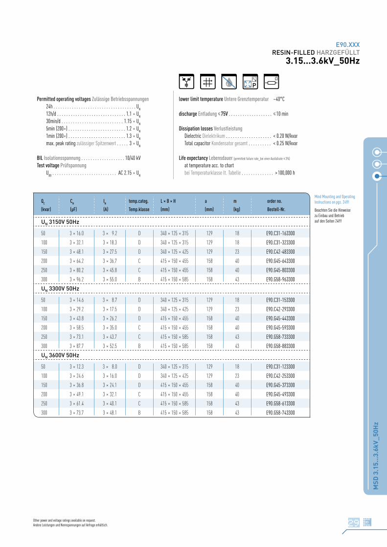
MSD
3.1
5...3
.6kV
_50H
z
29
E90.XXXRESIN-FILLED HARZGEFÜLLT
3.15...3.6kV_50Hz
Mind Mounting and Operating Instructions on pgs. 24ff!
Beachten Sie die Hinweise zu Einbau und Betrieb auf den Seiten 24ff!
Other power and voltage ratings available on request.Andere Leistungen und Nennspannungen auf Anfrage erhältlich.
Permitted operating voltages Zulässige Betriebsspannungen24h . . . . . . . . . . . . . . . . . . . . . . . . . . . . . . . . . . . . U
N
12h/d . . . . . . . . . . . . . . . . . . . . . . . . . . . . . . 1.1 x UN
30min/d . . . . . . . . . . . . . . . . . . . . . . . . . . . 1.15 x UN
5min (200x) . . . . . . . . . . . . . . . . . . . . . . . . . 1.2 x UN
1min (200x) . . . . . . . . . . . . . . . . . . . . . . . . . 1.3 x UN
max. peak rating zulässiger Spitzenwert . . . . . 3 x UN
BIL Isolationsspannung . . . . . . . . . . . . . . . . . . . 10/40 kVTest voltage Prüfspannung
UBB
. . . . . . . . . . . . . . . . . . . . . . . . . . . . AC 2.15 x UN
lower limit temperature Untere Grenztemperatur –40°C
discharge Entladung 75V . . . . . . . . . . . . . . . . . . . 10 min
Dissipation losses VerlustleistungDielectric Dielektrikum . . . . . . . . . . . . . . . . . . . . < 0.20 W/kvarTotal capacitor Kondensator gesamt . . . . . . . . . . < 0.25 W/kvar
Life expectancy Lebensdauer (permitted failure rate_bei einer Ausfallrate 3%)
at temperature acc. to chartbei Temperaturklasse lt. Tabelle . . . . . . . . . . . . . . > 100,000 h
QC CN IN temp.categ. L x B x H a m order no.
(kvar) (µF) (A) Temp.klasse (mm) (mm) (kg) Bestell-Nr.
UN 3150V 50Hz
50 3 x 16.0 3 x 9.2 D 340 x 125 x 315 129 18 E90.C31-163300
100 3 x 32.1 3 x 18.3 D 340 x 125 x 315 129 18 E90.C31-323300
150 3 x 48.1 3 x 27.5 D 340 x 125 x 425 129 23 E90.C42-483300
200 3 x 64.2 3 x 36.7 C 415 x 150 x 455 158 40 E90.G45-643300
250 3 x 80.2 3 x 45.8 C 415 x 150 x 455 158 40 E90.G45-803300
300 3 x 96.2 3 x 55.0 B 415 x 150 x 585 158 43 E90.G58-963300
UN 3300V 50Hz
50 3 x 14.6 3 x 8.7 D 340 x 125 x 315 129 18 E90.C31-153300
100 3 x 29.2 3 x 17.5 D 340 x 125 x 425 129 23 E90.C42-293300
150 3 x 43.8 3 x 26.2 D 415 x 150 x 455 158 40 E90.G45-443300
200 3 x 58.5 3 x 35.0 C 415 x 150 x 455 158 40 E90.G45-593300
250 3 x 73.1 3 x 43.7 C 415 x 150 x 585 158 43 E90.G58-733300
300 3 x 87.7 3 x 52.5 B 415 x 150 x 585 158 43 E90.G58-883300
UN 3600V 50Hz
50 3 x 12.3 3 x 8.0 D 340 x 125 x 315 129 18 E90.C31-123300
100 3 x 24.6 3 x 16.0 D 340 x 125 x 425 129 23 E90.C42-253300
150 3 x 36.8 3 x 24.1 D 415 x 150 x 455 158 40 E90.G45-373300
200 3 x 49.1 3 x 32.1 C 415 x 150 x 455 158 40 E90.G45-493300
250 3 x 61.4 3 x 40.1 C 415 x 150 x 585 158 43 E90.G58-613300
300 3 x 73.7 3 x 48.1 B 415 x 150 x 585 158 43 E90.G58-743300
P

E90.XXXRESIN-FILLED HARZGEFÜLLT6.3...7.1kV_50Hz
MSD
6.3
...7.
1kV_
50H
z
30 Other power and voltage ratings available on request.Andere Leistungen und Nennspannungen auf Anfrage erhältlich.
Permitted operating voltages Zulässige Betriebsspannungen24h . . . . . . . . . . . . . . . . . . . . . . . . . . . . . . . . . . . . U
N
12h/d . . . . . . . . . . . . . . . . . . . . . . . . . . . . . . 1.1 x UN
30min/d . . . . . . . . . . . . . . . . . . . . . . . . . . . 1.15 x UN
5min (200x) . . . . . . . . . . . . . . . . . . . . . . . . . 1.2 x UN
1min (200x) . . . . . . . . . . . . . . . . . . . . . . . . . 1.3 x UN
max. peak rating zulässiger Spitzenwert . . . . . 3 x UN
BIL Isolationsspannung . . . . . . . . . . . . . . . . . . . 20/60 kVTest voltage Prüfspannung
UBB
. . . . . . . . . . . . . . . . . . . . . . . . . . . . AC 2.15 x UN
lower limit temperature Untere Grenztemperatur –40°C
discharge Entladung 75V . . . . . . . . . . . . . . . . . . 10 min
Dissipation losses VerlustleistungDielectric Dielektrikum . . . . . . . . . . . . . . . . . . . . < 0.20 W/kvarTotal capacitor Kondensator gesamt . . . . . . . . . . < 0.25 W/kvar
Life expectancy Lebensdauer (permitted failure rate_bei einer Ausfallrate 3%)
at temperature acc. to chartbei Temperaturklasse lt. Tabelle . . . . . . . . . . . . . > 100,000 h
QC CN IN temp.categ. L x B x H a m order no.
(kvar) (µF) (A) Temp.klasse (mm) (mm) (kg) Bestell-Nr.
UN 6300V 50Hz
50 3 x 4.0 3 x 4.6 D 340 x 125 x 315 129 18 E90.C31-402300
100 3 x 8.0 3 x 9.2 D 340 x 125 x 425 129 23 E90.C42-802300
150 3 x 12.0 3 x 13.7 D 340 x 125 x 425 129 23 E90.C42-123300
200 3 x 16.0 3 x 18.3 D 415 x 150 x 455 158 40 E90.G45-163300
250 3 x 20.0 3 x 22.9 C 415 x 150 x 585 158 43 E90.G58-203300
300 3 x 24.1 3 x 27.5 C 415 x 150 x 585 158 43 E90.G58-243300
UN 6600V 50Hz
50 3 x 3.7 3 x 4.4 D 340 x 125 x 315 129 18 E90.C31-372300
100 3 x 7.3 3 x 8.7 D 340 x 125 x 425 129 23 E90.C42-732300
150 3 x 11.0 3 x 13.1 D 415 x 150 x 455 158 40 E90.G45-113300
200 3 x 14.6 3 x 17.5 D 415 x 150 x 455 158 40 E90.G45-153300
250 3 x 18.3 3 x 21.9 C 415 x 150 x 585 158 43 E90.G58-183300
300 3 x 21.9 3 x 26.2 C 415 x 150 x 585 158 43 E90.G58-223300
UN 7100V 50Hz
50 3 x 3.2 3 x 4.1 D 340 x 125 x 315 129 18 E90.C31-322300
100 3 x 6.3 3 x 8.1 D 340 x 125 x 425 129 23 E90.C42-632300
150 3 x 9.5 3 x 12.2 D 415 x 150 x 455 158 40 E90.G45-952300
200 3 x 12.6 3 x 16.3 D 415 x 150 x 455 158 40 E90.G45-133300
250 3 x 15.8 3 x 20.3 C 415 x 150 x 585 158 43 E90.G58-163300
300 3 x 18.9 3 x 24.4 C 415 x 150 x 585 158 43 E90.G58-193300
P
Mind Mounting and Operating Instructions on pgs. 24ff!
Beachten Sie die Hinweise zu Einbau und Betrieb
auf den Seiten 24ff!

E90.XXXRESIN-FILLED HARZGEFÜLLT
10.5...11.8kV_50Hz
MSD
10.
5...1
1.8k
V_50
Hz
31
Permitted operating voltages Zulässige Betriebsspannungen24h . . . . . . . . . . . . . . . . . . . . . . . . . . . . . . . . . . . . U
N
12h/d . . . . . . . . . . . . . . . . . . . . . . . . . . . . . . 1.1 x UN
30min/d . . . . . . . . . . . . . . . . . . . . . . . . . . . 1.15 x UN
5min (200x) . . . . . . . . . . . . . . . . . . . . . . . . . 1.2 x UN
1min (200x) . . . . . . . . . . . . . . . . . . . . . . . . . 1.3 x UN
max. peak rating zulässiger Spitzenwert . . . . . 3 x UN
BIL Isolationsspannung . . . . . . . . . . . . . . . . . . . 28/75 kVTest voltage Prüfspannung
UBB
. . . . . . . . . . . . . . . . . . . . . . . . . . . . AC 2.15 x UN
lower limit temperature Untere Grenztemperatur –40°C
discharge Entladung 75V . . . . . . . . . . . . . . . . . . . 10 min
Dissipation losses VerlustleistungDielectric Dielektrikum . . . . . . . . . . . . . . . . . . . . < 0.20 W/kvarTotal capacitor Kondensator gesamt . . . . . . . . . . < 0.25 W/kvar
Life expectancy Lebensdauer (permitted failure rate_bei einer Ausfallrate 3%)
at temperature acc. to chartbei Temperaturklasse lt. Tabelle . . . . . . . . . . . . . . > 100,000 h
QC CN IN temp.categ. L x B x H a m order no.
(kvar) (µF) (A) Temp.klasse (mm) (mm) (kg) Bestell-Nr.
UN 10500V 50Hz
150 3 x 4.3 3 x 8.2 D 415 x 150 x 455 158 40 E90.G45-432300
200 3 x 5.8 3 x 11.0 D 415 x 150 x 455 158 40 E90.G45-582300
250 3 x 7.2 3 x 13.7 D 415 x 150 x 585 158 43 E90.G58-722300
300 3 x 8.7 3 x 16.5 D 415 x 150 x 585 158 43 E90.G58-872300
400 3 x 11.5 3 x 22.0 C 415 x 150 x 715 158 53 E90.G71-123300
UN 10900V 50Hz
150 3 x 4.0 3 x 7.9 D 415 x 150 x 455 158 40 E90.G45-402300
200 3 x 5.4 3 x 10.6 D 415 x 150 x 455 158 40 E90.G45-542300
250 3 x 6.7 3 x 13.2 D 415 x 150 x 585 158 43 E90.G58-672300
300 3 x 8.0 3 x 15.9 D 415 x 150 x 585 158 43 E90.G58-802300
400 3 x 10.7 3 x 21.2 C 415 x 150 x 715 158 53 E90.G71-113300
UN 11800V 50Hz
150 3 x 3.4 3 x 7.3 D 415 x 150 x 455 158 40 E90.G45-342300
200 3 x 4.6 3 x 9.8 D 415 x 150 x 455 158 40 E90.G45-462300
250 3 x 5.7 3 x 12.2 D 415 x 150 x 585 158 43 E90.G58-572300
300 3 x 6.9 3 x 14.7 D 415 x 150 x 585 158 43 E90.G58-692300
400 3 x 9.1 3 x 19.6 C 415 x 150 x 715 158 53 E90.G71-912300
Other power and voltage ratings available on request.Andere Leistungen und Nennspannungen auf Anfrage erhältlich.
P
Mind Mounting and Operating Instructions on pgs. 24ff!
Beachten Sie die Hinweise zu Einbau und Betrieb auf den Seiten 24ff!

E90.XXXRESIN-FILLED HARZGEFÜLLT2.4...4.16kV_60Hz
MSD
2.4
...4.
16kV
_60H
z
32 Other power and voltage ratings available on request.Andere Leistungen und Nennspannungen auf Anfrage erhältlich.
Permitted operating voltages Zulässige Betriebsspannungen24h . . . . . . . . . . . . . . . . . . . . . . . . . . . . . . . . . . . . U
N
12h/d . . . . . . . . . . . . . . . . . . . . . . . . . . . . . . 1.1 x UN
30min/d . . . . . . . . . . . . . . . . . . . . . . . . . . . 1.15 x UN
5min (200x) . . . . . . . . . . . . . . . . . . . . . . . . . 1.2 x UN
1min (200x) . . . . . . . . . . . . . . . . . . . . . . . . . 1.3 x UN
max. peak rating zulässiger Spitzenwert . . . . . 3 x UN
BIL Isolationsspannung 2400V . . . . . . . . . . . . . 13/45 kV 4160V . . . . . . . . . . . . . 24/75 kVTest voltage Prüfspannung
UBB
. . . . . . . . . . . . . . . . . . . . . . . . . . . . AC 2.15 x UN
lower limit temperature Untere Grenztemperatur –40°C
discharge Entladung 75V . . . . . . . . . . . . . . . . . . . 10 min
Dissipation losses VerlustleistungDielectric Dielektrikum . . . . . . . . . . . . . . . . . . . . < 0.20 W/kvarTotal capacitor Kondensator gesamt . . . . . . . . . . < 0.25 W/kvar
Life expectancy Lebensdauer (permitted failure rate_bei einer Ausfallrate 3%)
at temperature acc. to chartbei Temperaturklasse lt. Tabelle . . . . . . . . . . . . . . . > 100,000 h
QC CN IN temp.categ. L x B x H a m order no.
(kvar) (µF) (A) Temp.klasse (mm) (mm) (kg) Bestell-Nr.
UN 2400V 60Hz
50 3 x 23.0 3 x 12.0 D 340 x 125 x 315 129 18 E90.C31-233399
100 3 x 46.1 3 x 24.1 D 340 x 125 x 425 129 23 E90.C42-463400
150 3 x 69.1 3 x 36.1 D 340 x 125 x 425 129 23 E90.C42-693400
200 3 x 92.1 3 x 48.1 C 415 x 150 x 455 158 40 E90.G45-923400
250 3 x 115.1 3 x 60.1 C 415 x 150 x 455 158 40 E90.G45-124400
300 3 x 138.2 3 x 72.2 B 415 x 150 x 585 158 43 E90.G58-144399
UN 4160V 60Hz
50 3 x 7.7 3 x 6.9 D 340 x 125 x 315 129 18 E90.C31-772400
100 3 x 15.3 3 x 13.9 D 340 x 125 x 425 129 23 E90.C42-153400
150 3 x 23.0 3 x 20.8 D 340 x 125 x 425 129 23 E90.C42-233400
200 3 x 30.7 3 x 27.8 C 415 x 150 x 455 158 40 E90.G45-313400
250 3 x 38.3 3 x 34.7 C 415 x 150 x 455 158 40 E90.G45-383400
300 3 x 46.0 3 x 41.6 B 415 x 150 x 585 158 43 E90.G58-463400
P
Mind Mounting and Operating Instructions on pgs. 24ff!
Beachten Sie die Hinweise zu Einbau und Betrieb
auf den Seiten 24ff!

NOTIZENNOTES
NO
TIZE
N_N
OTE
S
33
NOTESNOTIZEN
NO
TIZE
N_N
OTE
S
34 We reserve the right to make technical changes without prior notice. No liability can be assumed for the accuracy of data content.Technische Änderungen ohne gesonderte Benachrichtigung vorbehalten. Für fehlerhafte Informationen kann keine Haftung übernommen werden.
P 731/07Printed by druckspecht GmbH
© 2007 ELECTRONICON Kondensatoren GmbH. All rights reserved.