M.Sc. Lec-13-Plastic Analysis and Design
79
CONNECTIONS • Connections are the devices used to join elements of a structure together at a point such that forces can be transferred between them safely. • Connection design is more critical than the design of members. • The failure of connection usually means collapse of a greater part or whole of the structure. • In general, relatively more factor of safety is provided in the design of connections.
Transcript of M.Sc. Lec-13-Plastic Analysis and Design

CONNECTIONS• Connections are the devices used to join elements
of a structure together at a point such that forces can be transferred between them safely.
• Connection design is more critical than the design of members.
• The failure of connection usually means collapse of a greater part or whole of the structure.
• In general, relatively more factor of safety is provided in the design of connections.

• The connections shall be designed for a minimum strength of 44 kN, except for lacing, sag rods, or girts.
• The rigid connection should provide sufficient strength and ductility.
• The ductility is very useful for redistribution of stresses and dissipation of extra energy in case of earthquakes, etc.

TYPES OF CONNECTIONS
Based On Means Of Connection
A. Welded connectionsB. Riveted connectionsC. Bolted connections

Based On Forces To Be Transferred
A. Truss connectionsB. Simple / shear connectionsC. Moment connections
– i) Fully restrained (FR) connections– ii) Partially restrained (Semi-rigid) connections
D. SplicesE. BracketsF. Bearing joints

BUILDING / FRAME / BEAM CONNECTIONS
• Fully Restrained / FR / Moment Connections
• Partially Restrained / PR Connectionsa. Simple or shear or flexible
connectionsb. Semi-rigid connectionsc. Bearing joints of compression
members

Moment Connections• Moment connections are also referred to as rigid,
continuous frame or FR connections.
• Knee joints are the typical example.
• They are assumed to be sufficiently rigid keeping the original angles between members practically unchanged after application of loads.
• Greater than 90 percent moment may be transferred with respect to ideally rigid connection besides the full transfer of shear and other forces.

• These connections are particularly useful when continuity between the members of the building frame is required to provide more flexural resistance and to reduce lateral deflection due to wind loads.
• Both the flanges and web of the member are to be connected for this type of connection.

Partially Restrained Connections• Type PR connections have rigidity less than 90 percent
compared with ideally rigid connections. • Although the relative rotation between the joining
members is not freely allowed, the original angles between members may change within certain limits.
• They transfer some percentage of moment less than 90 percent and full shear between the members.
• PR connections may be further classified into simple and semi-rigid connections.

Shear Connections
• Simple or shear connections have less than 20 percent rigidity.
• They are considerably flexible and the beams become simply supported due to the possibility of the large available rotation.
• Moment may not be transferred in larger magnitudes with the requirement that the shear force is fully transferred.

• In these connections, primarily the web is to be connected because most of the shear stresses are concentrated in it.
• Connections of beams, girders, or trusses shall be designed as flexible joints to resist only the reaction shears except otherwise required.
• Flexible beam connections shall accommodate end rotations of unrestrained beams.

Semi-Rigid Connections• Semi-rigid connections provide rigidity in-
between fully restrained and simple connections. • Approximately 20 to 90 percent moment
compared with ideal rigid joint may be transferred. • End moments may develop in the beams and the
maximum beam moment may be significantly reduced.
• Usually no advantage is taken of this reduction and beams are designed as simply supported because of various reasons.

• One of the reasons is the difficulty of structural frame analysis for varying degrees of restraints at the joints and unpredicted rotations.
• Further, LRFD Specification states that a connection can only be considered as semi-rigid if proper evidence is presented to prove that it is capable of providing a certain end restraint.
• These are the commonly used types of connections in practice because their performance is exceptionally well under cyclic loads and earthquake loadings.

Bearing Joints
• There shall be sufficient connectors to hold all parts of the section securely in place when columns rest on bearing plates.
• All compression joints shall be designed to provide resistance against uplift and tension developed during the uplift load combination.

MOMENT CONNECTIONSRigid Frame Knees• These are a type of fully restrained (FR) or
moment connection. • In the design of rigid frames the safe
transmission of load at the junction of beam and column is of great importance.
• When members join with their webs lying in the plane of the frame, the junction is frequently referred to as a knee joint.

Typical knee joints are:
Square Knees, with and without a diagonal stiffener, are shown in Figure 8.31.
Column or beam section may be continued through the junction.

θ
a) Square Knee Without Stiffener b) Square Knee With Stiffener
Figure 8.31. Square Knee Joints.

Square Knee With a Bracket is shown in Figure 8.32.
This type of joint may resist large negative moments reducing the size of the beam and the column.

Figure 8.32. Square Knee With a Bracket.

Straight Haunched Knee is a modification of the square knee with a bracket.
The beam and column sections are discontinued short of the connection.
The haunch consists of a separate plate reinforced by perpendicular stiffeners (see Figure 8.33).

Figure 8.33. Straight Haunched Knee.

Curved Haunched Knee is similar to a straight haunched knee with the difference of having a curved inner profile, as shown in Figure 8.34.
Figure 8.34. Curved Haunched Knee.

For haunched knees, variable moment of inertia has to be considered with the knees for both beams and column to perform analysis.
To be adequately designed, a knee connection must satisfy the following requirements:

1. The end moment between the beam and the column must be transferred.
2. The beam end shear must safely go to the column.
3. The shear at the top of the column should be transferred into the beam.
4. The joint must deform in a manner consistent with the analysis by which moments and shears are determined.
5. If a plastic hinge associated with the failure mechanism is expected to form at or near the knee, adequate rotation capacity must be built into the connections.

• Square knees have the greatest plastic rotation capacity but this flexibility increases the service load deflections as they deform elastically the most under the loads.
• Curved knees are the most stiff but have the least rotation capacity.
• Since straight tapered knees provide reasonable stiffness along with adequate rotation capacity, in addition to the fact that they are cheaper than curved haunches to fabricate, the straight haunched knees are more commonly used.

Shear Transfer In Square Knees• In the design of a rigid frame having square
knees, two rolled sections may come together at right angles.
• The moments, shears and axial forces (M, V and H) acting on the boundaries of the square knee region, as shown in Figure 8.35(a), may be determined by either elastic or plastic analysis.
• The forces carried by the flanges must be transmitted by shear into the web, as shown in (b) part of the same figure.

(a)
WEBBA
D C Tc
Tb
From tension in left flange of column
From compression in bottom flange of beam
From tension in top flange of beam
From compression in right flange of column
(b)
Cb
Tb
db
≈dc
CcTc
BA
D C
M H
MH
V
V
Figure 8.35. Forces Acting on Web of a Square Knee.

Assuming all bending moment to be carried by the flanges, and approximating the distance between flange centroids as 0.95 db, the flange force is:
Tu = Tb = b
ud95.0
M
The nominal shear strength of the web across the edge AB is:
Vn = Vab = τy tw dcwhere τy = 0.6 Fy and φν = 0.9

For design, φ Vn = Tu, which gives:
φν (0.6 Fy) tw dc = b
u
dM95.0
Required tw without diagonal stiffener =
=
cby
u
ddFM95.1
bcy
u
AFM95.1
where Abc = the planner area within the knee = db dc.

Diagonal Stiffeners
• In a rigid frame knee, the required web thickness usually exceeds that provided by a W-section and reinforcement is required.
• A doubler plate is sometimes used to thicken the web region, which is not a general practical solution because of the difficulty of making the attachment to the column web.
• Usually, a pair of diagonal stiffeners is the best solution, as shown in Figure 8.37.

Cst cos θ
Cst
θ
A B
D C
Figure 8.37. Web of a Square Knee Connection With a Stiffener.

• Stiffener resistive compressive force= Cst
= Ast φc Fcr
• Applied shear on the web ( Figure 8.35 (b))= Tu
• When diagonal stiffeners are used, the horizontal component Cst×cosθ of the stiffener force participates in resisting the shear with the web.

ΣFx = 0 ⇒Tu = Vab + Cst cos θ
= φν (0.60 Fy) tw dc + Ast φcFcr cos θb
ud95.0
M
Ast, req = ( )
− cwy
b
u
crc
dtFd
MF
60.095.0cos
1νφθφ
where φν = 0.90 for any yield limit state like in shear
φc = 0.85 for compression elements
Fcr = compression limit state stress

Example 8.6
Design the square knee connection given in Figure 8.38 to join a W690 × 140 girder to a W360 × 110 column. The factored moment Muto be carried through the joint is 510 kN-m. Use A36 steel and E70 electrodes with SMAW.

285 kN
510 kN-m
67 kN
285 kN
67 kN510 kN-m
B
A
DC
θ
W360 × 110
W690 × 140
db = 684 mm(tw)b = 12.4 mmtf = 18.9 mmbf = 254 mm
dc = 360 mm(tw)c = 11.4 mmtf = 19.9 mmbf = 256 mm
Figure 8.38. Square Knee of Example 8.6.

SolutionCheck the web without diagonal stiffener:
Required tw =
=
= 16.15 mm
bcy
u
AFM95.1
3606842501051095.1 6
××××
Actual tw = 12.4 mm for W690 × 140< 16.15 mm
∴ A diagonal stiffener is required.

Stiffener size:
tan θ = =
⇒ θ = 62.24° and cos θ = 0.466c
bdd
360684
Assuming Fcr ≅ 0.95Fy,
(Ast)req =
××××−
××
××3604.1225060.09.0
68495.010510
466.023885.01 6
= 1933 mm2
(half area on one side = 967 mm2)

Using tst = 12 mm ; bst = 81 mmsay 85 mm
λ = = 7.08 < λr = 15.8 OK
Size of stiffener:2 PL s 12 × 85 on both sides of the web
Strength of the stiffener acting as a column:
Overall width of stiffener = b = 2 bst + tw
= 2 × 85 + 12.4 = 182.4 mm
1285

r = = = 0.289 b
= 52.65 mm
( )bt
12bt
st
3st ( )b
121
= = ≅ 15
∴ φc Fcr ≈ 201.88 MPa
rKL
rcosdc θ
65.52466.0360
This means that Fcr is equal to the assumed value of Fcr.

Determine the fillet weld size along length AB. The weld must transmit the factored flange force into the beam web. The maximum design flange force that can be developed is φt Fy Af.
Flange force = φt Fy Af = 0.90 × 250 × 19.9 ×256/1000 = 1146.24 kN
The design strength of fillet welds along both sides of web is:
φ Rnw = 2(0.75 × 0.707 × tw × 0.6 × 495/1000) = 0.315 tw kN/mm

Available length for weld = db – 2 tf
= 684 – 2 × 18.9 = 646.2 mm
∴ 0.315 tw (646.2) = 1146.24
tw = 6 mm
Use 6 mm thick E70 fillet weld along length AB (both sides of girder web)

Determine fillet weld size along length BC. The connection of the column web to the beam flange must carry the force resulting from flexure and axial load, combined with the shear acting simultaneously on the weld.
The forces transferred through this weld may conservatively be estimated as follows:
Tensile component = φt Fy tw
= 0.9 × 250 × 12.4/1000 = 2.79 kN/mm

Shear component = =
= 0.21 kN/mm
fc
utd
V2− 9.192360
67×−
Resultant loading = = 2.80 kN/mm22 21.079.2 +
Required tw = ≅ 9 mm315.080.2
Use 9 mm thick E70 fillet weld along length BC on both sides of girder web

Weld required along diagonal stiffeners is designed next. This weld must develop the required stiffener strength.
φ Cs = φ Fy Ast
= 0.9 × 250 × 2 × 12 × 80/1000 = 432 kN
Required tw = = 1 mmsay 6 mm
( )495.06.0707.075.04
466.0360432××××
Use 6mm thick E70 fillet weld along diagonal stiffener on both sides of girder web

Determine the required length of the stiffener CD:
The design strength based on local web yielding from the inside column flange at C is:
Pbf = φ (5 k + tfb) Fyc twc= 1.0(5 × 37 + 18.9) × 250 × 11.4/1000 = 581.12 kN
Flange force as calculated earlier = 1146.24 kN
The force is greater than capacity of the web alone and diagonal stiffener is already resisting other forces. Hence, vertical stiffener is required at C.

Stiffener along CD:
Required Ast =
= 1256 mm2 per plate
2112581241146
×−
yF..
φ
Width available = =
= 120.8 mm say 110 mm
2wbfb tb −
24.12254−
Required tst = ≅ 12 mm110
1256
λ = = 9.17 < λp = 10.8 OK12110
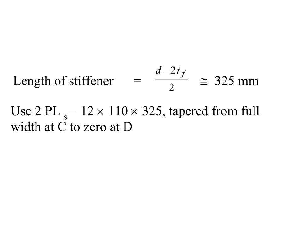
Length of stiffener = ≅ 325 mm22 ftd −
Use 2 PL s – 12 × 110 × 325, tapered from full width at C to zero at D

Steel StructuresCentral Moment Connection
Vertical stiffeners
Horizontal stiffeners
Vertical stiffeners / column flanges give extra strength to web against web crippling. Horizontal stiffener is similar to bearing stiffener. If we don't provide hz. stiffener then beam-flange force will act as point load so web crippling can occur.

Steel StructuresDiagonal Stiffener for Shear
Flange stiffener
1uC
1uT
2uT
2uC
1bd 2bd
1bd95.02bd95.0
A B
CD
1uM2uM
3uM
4uM
θα
uV
cd
Diagonal or Shear stiffener
αsinf
st
tt =Thickness =
Column moments are considered opposite to beam moments
Vu = Column shear

Steel Structures
2b0.95d2u
2uMT =
2b0.95d2u
2uMC =
Flange stiffener can be tapered as well.
−
= −
1b2b
c1
dddtanα
Design of Flange stiffeners:
Case I:
If flange stiffener is a continuation of two flanges (on both sides), the size of the stiffener is kept equal to the larger flange. This thickness of the larger flange may gradually be decreased to the size of the smaller flange on the other side.

If the stiffener is inclined, as in the bottom stiffener of the figure, the thickness of the stiffener has to be increased as follows:
αsin2f
st
tt =
)( where
12 bb
c
ddd−
=α
Case II:
If the flange stiffener is a continuation of flange only from one side, it is designed just like a bearing stiffener of a plate girder for the flange force.
If Ast is negative, no stiffener is required.
When this stiffener is required at outer end of a knee joint, size equal to the flange is preferred.
( )fbtwcfbst tktAA 5−=Area of stiffener

Steel Structures
T
T
C
C
Deformed shape
2uT
1uT
1uC
2uC
cduVA B
CD
θ2bd95.01bd95.0
Check For Web Without Shear Stiffener
Vu = factored shear in the column, it will be opposite to Tu2because the column moment will be opposite to larger beam moment for the joint equilibrium.

Steel StructuresStrength of ABCD Without Diagonal StiffenerConsidering the shear acting on edge AB of the web
u2u1u VTC −+=Total applied factored shear
Shear capacity of web, φvVn cwyv dtF6.0φ=
tw = Thickness of web within the joint.
uuucwyv VTCdtF −+= 216.0φ
u2d
2u
1d
1u Vb95.0
Mb95.0
M−+=
If db2 is used in place of bd1 the difference is small and it is one safer side as well, because usually Mu1 will be of opposite sign and lesser value of the corresponding term will give more resultant answer.

Steel StructuresStrength of ABCD Without Diagonal Stiffener
cy
u
cy2d
2u1ureqw dF6.09.0
VdF6.09.095.0
1b
MMt×
−××
×+
=
If no load is acting within the column, its inflection point will be almost at the mid-height.
( )cy
u
c2dy
2u1ureqw dF
V85.1dbF
MM95.1t −+
=
2hMV 3u
u ≅Further assume
3u4u MM ≅
hMM
hMM
hM2V 2u1u4u3u3u
u+
=+
==

Steel StructuresAssuming h ≈ 13bd
b
2u1uu d13
MMV +=
( ) ( )c2by
2u1u
c2by
2u1uwreq ddF13
MM85.1ddF
MM95.1t +−
+=
( )c2by
2u1uwreq ddF
MM81.1t +=
1.95 if Vu = 0
If (tw)available≥ (tw)req, no diagonal stiffener is required otherwise provide diagonal stiffener.

Steel StructuresStrength of Connection With Diagonal Stiffener
ub
uucrcstcwyv V
dMMFAdtF −
+=+
2
21
95.0cos6.0 θφφ
Other Cases
( )
×−
+= cwy
b
uu
crcreqst dtF
dMM
FA 6.09.0
025.1cos1
2
21
θφ
0.95 if Vu = 0
u2u MM =( )
cby
ureqw ddF
Mt 95.1=
( )
×= − cwy
b
u
crcreqst dtF
dM
FA 6.09.0
95.0cos1
θφ
0M 1u =
0Vu = b2b dd =
No column on top

Steel StructuresOther Cases: (contd…)
( )cby
ureqw ddF
M81.1t =
( )
×= − cwy
b
u
crcreqst dtF
dM
FA 6.09.0
025.1cos1
θφ

HAUNCHED CONNECTIONSHaunched knees may exhibit poor rotation capacity.
Either due to insufficient baring or due to inadequate proportions of the haunch itself, the knee may buckle laterally before the desired design conditions will reach.
Therefore, the design of a haunched connection for use in a plastically designed structure must embody both strength and stability considerations.
The haunch is proportioned with sufficient strength so that the plastic hinge is formed at the end of the haunch.
The haunch is proportioned and is braced in a manner that will provide adequate resistance to lateral buckling.

Basic AssumptionsFollowing assumptions are made for the design of tapered haunches:
1. The moment diagram is linear from the point of inflection (O) in the beam to the haunch point (H).
2. Plastic hinge is formed at the end of the rolled shape (section R).
3. The length O-R is approximately taken equal to 3db and represents about as severe a condition as might be encountered in practice.
4. Lateral support will at least be provided at the extremities andat the common intersection points of the haunch.
5. The width of the haunch flange is considered equal to that of the adjoining rolled section.

6. If the angle β is greater than about 12, the critical section will be at section R and no increase in the flange thicknesses of the haunch may be needed. If the angle β is less than 12, flange thicknesses are to be increased to provide moment at section 1 greater than M1.
7. Within the dimensions d1 and d2, the strength of the members in shear must also be checked.
Lateral Stability Without Bracing
If we want to avoid lateral bracing in-between the haunch, the flange thickness of the haunch is to be increased by the amount ∆t.
∆t = 0.1 (s / b −4) tt for β ≤ 24° s / b ≤ 17
tt = [1 + 0.1 (s / b −4)] tf for s / b > 4

Steel StructuresHaunch of a Gable Frame
1L
2L
γ 2db
F
1
12 2
HG
A
B
Cα
β
θ
2dc
2d
1d
1R
2R2s
1s L1, L2 = Length from haunch point H to section R1 and R2respectively.
Usually we design haunch in such a way that d1 = d2 = dh
γ = Inclination of girder w.r.thorizontal.

Steel StructuresHaunch of a Gable FrameRelationship Between θ & γ
hd
γ
γ
Ahd
θθ
θ90 −
Total angle at F = 90 + γ
245θ γ
−=
F
D
EAngle AFE = γ + θAngle EAF = 90 − (γ + θ)Two sides of the triangles ADF and AEF are equal and one angle is 90°, hence, these are similar.
Angle DFA = Angle EFA
90 − θ = γ + θ

Steel Structures
θtan2
dd1H bh
−=
θtan2
dd2H ch
−=
1HLBG 1 −=
−−
= −
1HLddtanβ
1
bh1
−−
= −
2HLddtan
2
ch1α
βsin1bh dds −
=
αsin2ch dds −
=
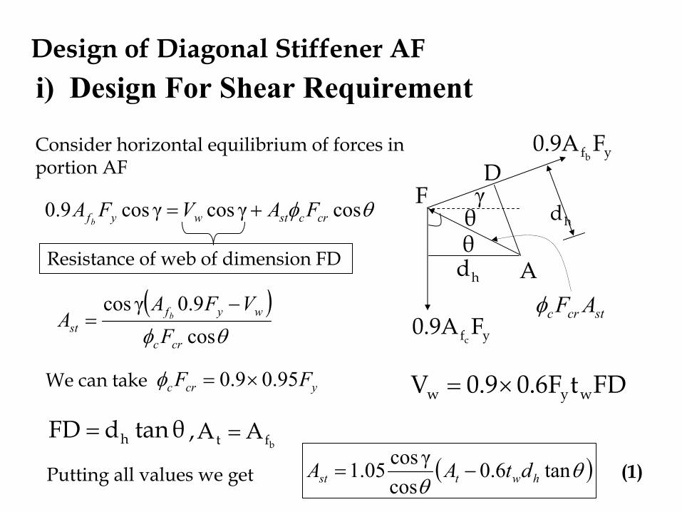
Design of Diagonal Stiffener AF
hdγ
Ahdθθ
Consider horizontal equilibrium of forces in portion AF
yf FA9.0b
yf FA9.0c
stcrc AFφ
θφ cosγcosγcos9.0 crcstwyf FAVFAb
+=
Resistance of web of dimension FD
( )θφ cos
9.0γcos
crc
wyfst F
VFAA b
−=
We can take ycrc FF 95.09.0 ×=φ FDtF6.09.0V wyw ×=
FD
θtandFD h=
Putting all values we get ( )θθ
tan6.0cos
γcos05.1 hwtst dtAA −=bft AA, =
(1)
i) Design For Shear Requirement

γ
F
A
B
Cα
β
θ
1d
1Rh
stcrc AFφ
2cA
stA
yc FA9.01
yc FA9.02
γ+β
γ
Transverse stiffener
αcos2
tcc
AA =
βcos1
tbc
AA =Fig:1
ii) Design For Axial Thrust Requirement Ac1 = area of lower beam haunch flangeAc2 = area of inner column haunch

∑ = 0Fx
From Fig:1
( ) αsin9.0γcos9.0cos21 ycyccrcst FAFAFA −+= βθφ
( )[ ]θφ
βcos
αsinγcos9.021
crc
ccyst F
AAFA
−+=
( )θ
βcos
αsinγcos05.1 21 cc
st
AAA
−+≅ 05.1
9.0=
crc
y
FF
φ(2)
Ast is calculated from Shear effect (1) and Axial effect (2) and greater value is selected.
ii) Design For Axial Thrust Requirement

Transverse Stiffener At End of Haunch
βφ sin9.01 ycstcrc FAAF =
If width is taken equal to other stiffeners / flange width
βφ
sin9.0
1ccrc
yst A
FF
A =
βsin05.11cst tt =
αsin05.12cst tt =
For R1
For R2
At the ends of the haunch (section R), transverse stiffeners arerequired for transmitting the compressive thrust.

Design Procedure1. Select the general proportions of the haunch, like its length
along the girder and column and horizontal depth of haunch (dh).
2. Calculate α, β, & γ and web thickness (mostly equal to larger girder and column web thicknesses).
3. Calculate moments due to loads at sections 1 and 2 and also at the junction of haunch with rolled section.
4. Check the plastic modulus furnished at the common intersection point (section 1). If it is considerably less thanthe value required from the moment diagram (M1), the depth dh must be increased.
The increased value may be evaluated from the following Equation.

(b − tw)2 tt − dh (b − tw) tt − tw /4 dh2 + Z1 = 0
5. Check s / b ratio and if it is greater than 4, increase the flange thickness.
6. Calculate the thickness of compression flange using the equation:
tc = tt / cos β
7. Repeat steps 4 to 6 for column portion of the haunch.
8. A diagonal stiffener is then proportioned, but its thickness must not be less than b / 17.
9. Finally transverse stiffeners are proportioned, but again their thicknesses must not be less than b / 17.

Steel StructuresExample: Design Haunch Connection
Beam Section: W 840 x 176
Column Section: W 840 x 251
The W360 condition for columns is not considered here because of presence of relatively larger bending moments.
γ = 25o
dh = 1200mm
Length of haunch along the girder = 3m
Length of haunch along the column= 2m
γ
6m
2m
m-3400kN
m-2267kN
m-3400kN
m-1400kN
3mR1
R2

γ
F
A
B
Cα
β
θ
1d
1Rh
stcrc AFφ
2cA
stA
yc FA9.01
yc FA9.02
γ+β
γ
Transverse stiffener
αcos2
tcc
AA =
βcos1
tbc
AA =Fig:1
Ac1 = area of lower beam haunch flangeAc2 = area of inner column haunch

Steel StructuresSolution:
m2L,m3L,mm1200d,25 21ho ====γ
mm14t,mm8.18t,mm292b,mm835d wff ====
o5.322
45θ =−=γ
mm4995.32tan2
8351200θtan2
dd1H bh =
−=
−=
mm491θtan2
dd2H ch =
−=
o1
2
1 7.1249120008591200tan
2HLdd
tan ch=
−−
=−
−= −−α
mm17t,mm31t,mm292b,mm859d wff ====Column
Girder

o
HLdd bh 3.8
49920008351200tan
1tan 1
1
1 =−−
=−
−= −−β
Steel Structures
mm 25283.8sin8351200
sin1 =−
=−
=β
bh dds
mm 15517.12sin
8591200sin2 =
−=
−=
αch dd
s
Let tw for the haunch web ≈ web thickness of column
= 18 mm

Steel StructuresSolution: (contd…)
mkN3067M1 −=
Plastic Section modulus available at section-1
γ
6m
2m
m-3400kN
m-2267kN
m-3400kN
m-1400kN
3mR1
R2
1M
2M
0.499m
0.491m
mkN3122M2 −=
tt = thickness of stiffener on tension side
Let tt = tf of beam ≈ 20mmbt = bf of beam ≈ 292mm
( ) ( ) 332tht1 10129462
4t-dbtZ mmtdt
thw ×=−+=
( ) 336
11 1013631
2509.0103067
9.0Z mm
FM
yreq ×=
××
==
( ) ( )reqavail 11 ZZ < 5% lessIf difference is larger increase architectural dimensions e.g. dh. If difference is smaller increase tension flange thickness

Steel StructuresSolution: (contd…)
( ) ( )reqavail 11 ZZ =Put and get tt from the resulting quadratic equation or do trials.
mm2.22tt =⇒ (Provide 25 mm thick outer stiffener)
For lateral stability of haunch
t1
t t4bs1.01t
−+=
466.829225281 >==
bs OK
( )[ ] mmtt 54.322.22466.81.01 =−+=
mmtt 35=Larger of 22.2 mm and 32.54mm, rounded up to available size.

Steel StructuresCompression Flange
mm 35cos
stability) gconsiderinnot (req. ≥=
βt
ctt
mmtc 35= 292x35mm
292x35mm
292x35mm292x35mm
Perform same calculations for column side
b = 292 mm, tt = 35.06mm
mmtc 3506.357.12cos
32=≥=
mmtc 35=Use for both stiffener
mm 3544.223.8cos
2.22≥== mm
tt = 32 mm is required for Z

Steel StructuresDiagonal Stiffener:For Shear:
( )θθ
tan6.0(req)cos
γcos05.11 hwtst dtAA −=
( )5.32tan1200186.0322925.32cos
25cos05.1 ××−×=
For column as this is greater than beam
21228mm=For Axial: ( )
θβ
cosαsin(req)γcos(req)
05.1 21
2
ccst
AAA
−+=
( ) 241975.32cos
12.7sin8.32292253.8cos44.2229205.1 mm=×−+×
=
241972
mmAst =

Steel StructuresSolution: (contd…)
Diagonal Stiffener:
mmmmbst 1351372
182922
≈=−
=
stb2ststst Atb2 =
mmb
At
st
stst 55.15
13524197
22 =
×==
For local stability
( ) mmbt stst 94.7
17min ==
So mmtst 55.15= say mmtst 18=
Steel StructuresTransverse Stiffener:
At R11R
2R
mm292b =
mm18,mm14tw =
From girder
From haunch
mm 135say 1372
18292 mmbst ≅−
=
( ) mmtst 5.128.10
135min ≅= Say 15 mm
mmtt cst 31.505.13.8sin3505.1sin11
=××=××= β
mm15tst =

Steel StructuresTransverse Stiffener:
At R21R
2R
mm292b =
mmmmtw 18,17=
From column
From haunch
mm 135say 1372
18292 mmbst ≅−
=
( ) mmtst 5.128.10
135min ≅= Say 15 mm
mmtt cst 08.805.17.12sin3505.1sin22
=××=××= α
mm15tst =