MRX-10 Installation Manual - Welcome to Aisle8 MMRRXX--EEDD IInnssttaallllaattiioonn Introduction...
11
63 MRX-10 Installation MRX-10 Installation Introduction When it comes to Total Control, no system is complete without an MRX-10. Acng as the system’s “brain,” the MRX-10 does all of the heavy liſting when it comes to control. Communicaon is the MRX-10’s strong point, both for incoming and outgoing commands. For incoming commands, the on-board RF transceiver accepts communicaon from the TRC-780 and returns status and metadata for true two-way feedback. All of the other remotes, keypads and touch panels in the Total Control line take this communicaon to the next level by using IP over the local area network (LAN). For outgoing commands to connected devices the MRX-10 is equipped for anything. Whether IR, RS-232, relays, triggers or sensors, the MRX-10 can control virtually any device. In addion, for IP controlled devices (thermostats, compable AV gear, energy management, home security, and others) the MRX-10 issues commands over the local network for control.
Transcript of MRX-10 Installation Manual - Welcome to Aisle8 MMRRXX--EEDD IInnssttaallllaattiioonn Introduction...

63
MRX-10 InstallationMRX-10 Installation
Introduction
When it comes to Total Control, no system is complete without an MRX-10. Acting as the system’s “brain,” the
MRX-10 does all of the heavy lifting when it comes to control.
Communication is the MRX-10’s strong point, both for incoming and outgoing commands. For incoming
commands, the on-board RF transceiver accepts communication from the TRC-780 and returns status and
metadata for true two-way feedback. All of the other remotes, keypads and touch panels in the Total Control
line take this communication to the next level by using IP over the local area network (LAN).
For outgoing commands to connected devices the MRX-10 is equipped for anything. Whether IR, RS-232,
relays, triggers or sensors, the MRX-10 can control virtually any device. In addition, for IP controlled devices
(thermostats, compatible AV gear, energy management, home security, and others) the MRX-10 issues
commands over the local network for control.

64
In the Total Control system, there is no more programming individual remotes. The MRX-10, as the brain of
the system, is the device that requires all of the programming. All control interfaces (remotes, keypads and
touch panels) are then “programmed” by the MRX-10 resulting in faster, more efficient programming.
Although the MRX-10 works perfectly well in a single-room installation, the real power of the Total Control
System comes when it is expanded to multiple rooms and controlling the “subsystems” in the home or
commercial space. Capable of extending its communication to other MRX-10s or MRX-1s (acting as “sub”
units), each “tethered” controller becomes part of the system and can receive/transmit commands through
the MRX-10.

65
Front and Rear Panel Descriptions
Front Panel
The front panel consists of 2 indicator lights illuminate when in use.
Power: Illuminates when the power supply is connected to an outlet.
Ethernet: Illuminates when connected to a Network Router. On=Connected, Off=Not Connected, Blinking =
attempting to connect.
Reset: Press for one second and release button located under the MRX-10 to restart the unit. Pressing and
holding the reset button for 15 seconds will set the unit to factory default.
Rear Panel
The rear panel ports are:
Power: Provides connection to included 12V/1Amp Power Supply.
LAN: Provides connection to LAN (Local Area network) via RJ45 cable. This essential connection is responsible
for:
Programming: Not only does the MRX-10 receive its programming over the network, it also issues
programming to connected remotes, keypads and touch panels through this port.
Communication: During normal operation, remote controls (except the TRC-780), keypads and touchpanels
send commands to the MRX-10 through the LAN port. These commands are then relayed to a control port
(IR, RS-232,relay or trigger) on the local MRX-10, or to one of the “sub” controllers.

66
Off-Site Programming: A constant internet connection is important if, at any future time, programming
changes are needed. Without this connection, a truck roll will be necessary to make these changes.
URC USB Port: USB port for future expansion.
IR Outputs: These fully adjustable routed outputs will only send IR commands to the specific device that each
emitter is attached to. This allows selective control of multiple same-brand, same-model components (multiple
DVD players, SAT receivers, etc.). It assures accurate control in that a given component’s commands are routed
only to its dedicated IR output and emitter, preventing IR splash from multiple emitters flashing at the same
time.
Relay NO, NC, COM: Provides configurable switch closure control.
Sensors: Provides connection to up to four URC Voltage Sensors (VS-1006) or URC Video Sensors (VID-6)
for status readings in sensor-based macros.
12V Output: Two programmable 12V/0.2A outputs. Each may be programmed to turn on, off or momentarily
toggle its output.
RS-232 Ports: Four 3.5mm RS232 ports provide direct control. Optional RS-232 adapters are required to use
these ports.
Trigger In: IR and RF trigger input ports allow integration with other control systems and remotes.
RFTX-1: Dedicated port for connection of optional RFTX-1 Transmitter for control of URC Lighting in a 75’-100’
range.
67
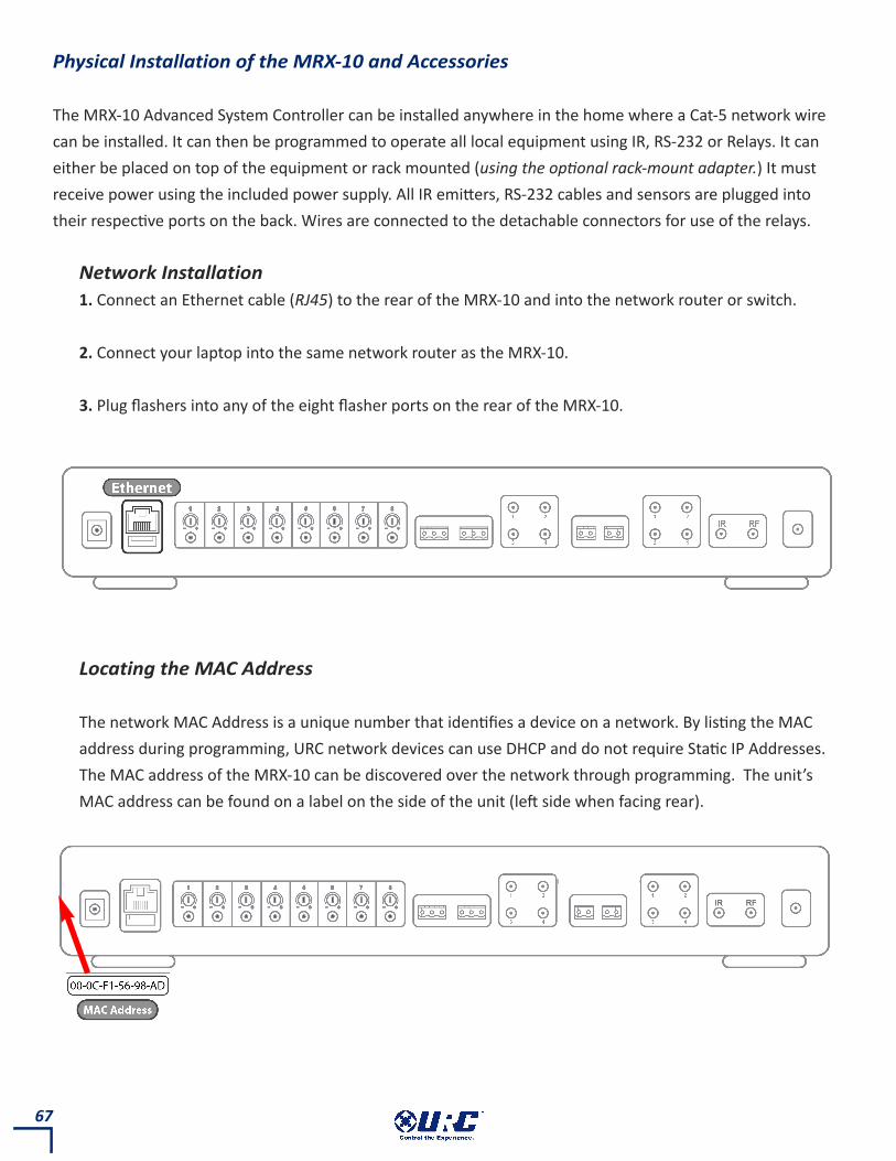
Physical Installation of the MRX-10 and Accessories
The MRX-10 Advanced System Controller can be installed anywhere in the home where a Cat-5 network wire
can be installed. It can then be programmed to operate all local equipment using IR, RS-232 or Relays. It can
either be placed on top of the equipment or rack mounted (using the optional rack-mount adapter.) It must
receive power using the included power supply. All IR emitters, RS-232 cables and sensors are plugged into
their respective ports on the back. Wires are connected to the detachable connectors for use of the relays.
Network Installation
1. Connect an Ethernet cable (RJ45) to the rear of the MRX-10 and into the network router or switch.
2. Connect your laptop into the same network router as the MRX-10.
3. Plug flashers into any of the eight flasher ports on the rear of the MRX-10.
Locating the MAC Address
The network MAC Address is a unique number that identifies a device on a network. By listing the MAC
address during programming, URC network devices can use DHCP and do not require Static IP Addresses.
The MAC address of the MRX-10 can be discovered over the network through programming. The unit’s
MAC address can be found on a label on the side of the unit (left side when facing rear).

68
Optimizing IR Flasher Levels
Test a few commands for each device before fixing the flasher in place on the front panel of a device. Since
TiVo, Replay TV, Satellite Receivers and Cable Boxes are all extremely sensitive to IR overload or saturation,
you should test them thoroughly. Put up the on-screen guide and test the navigation arrows. Compare
operation via RF to the original remote control. Operation should be identical. If operation is inconsistent
or sluggish, lower the IR line output and/or reposition the flasher.
If you still have sluggish operation, check that the remote control is set to a particular LINE OUT, rather
than ALL. When IR commands are sent to all the flashers in a cabinet, you can have difficulty adjusting the
IR Output. Reprogram the remote control to send IR commands only via a specific (1-8) Line Output, then
readjust the IR Line Output level.
1. Connect an IR emitter to each IR output and run the emitter wire to the front panel of each component.
DO NOT STICK the emitter in place. ADJUST the level first.
2. Adjust each of the IR Output levels with the included adjustment tool for best operation. If the
component operates best at minimum level, but is still operating sluggishly or intermittently, move the
emitter farther away from the component’s IR sensor.

69
RS-232 Connection
The MRX-10 can operate equipment via RS-232 communication. This allows discrete serial commands
to be triggered from a Total Control remote and sent from the MRX-10 over the network connection.
The signal is then sent to the device over proprietary URC RS-232 cables. These use either male or
female DB-9 connections with standard pin-outs. Programming is done in the Accelerator software.

70
Connecting a POWER sensor to a
third party device.
Connecting a VIDEO sensor to a
third party device.
Hint: If using a video sensor on a
component output, connect the sensor to
the GREEN (Y) output.
Using Power/Video Sensors with the MRX-10
The MRX-10 can use either a Video (composite) or Voltage signal to determine the power status of the
equipment it controls. This can then be used to alter the function of a Macro by using IF/ELSE
statements in the programming software. Using a VID-1 Video Sensor cable, the MRX-10 can detect a
video signal from a Composite or Component video output. The VS-100 Voltage Sensor will detect a
Voltage of 3-25V either AC or DC.

71
Wiring to the Relay on the MRX-10
The MRX-10 has a Relay with three contacts, NO, NC, and Com. These can be used as dry contacts or to
send a current to an electrical switch or motor for use with screens, blinds, curtains, etc. The Relay can
be used as either a latching contact or a momentary contact depending on the programming. The
command to actuate the Relay is programmed using the Accelerator software and is sent from the
MRX-10 when triggered by any Total Control system remote.

Application Diagram
72

73
RFTX-1
This device connects to the rear of the MRX-10 and provides direct
control of URC Lighting products from the MRX-10. This is not necessary
if there is an RFTX-1 connected to a MRX-1, and it is within range of the
local room.
VID-6
This video sensor cable is designed to connect to a sensor port on the
MRX-10 (or MRX-1). Using URC Accelerator programming software, a
Macro can be programmed to react to the status of this sensor.
VS-1006
This voltage sensor cable is designed to connect to a sensor port on the
MRX-10 (or MRX-1). Using URC Accelerator programming software, a
Macro can be programmed to react to the status of this sensor.
RS232M/RS232F
Available with either male or female RS-232 connectors, this cable
converts the RS-232 to a 3.5mm plug that can be connected to the
MRX-10 (or MRX-1) for communication.