Mri artifacts
48
MRI ARTIFACTS A.SHAJITHA B SC RADIOLOGY MADRAS MEDICAL COLLEG
-
Upload
shajitha-khan -
Category
Education
-
view
646 -
download
5
Transcript of Mri artifacts

MRI ARTIFACTS
A.SHAJITHA
B SC RADIOLOGY
MADRAS MEDICAL COLLEGE

What is an artifact??
An image artifact is a structure not normally
present.
But visible as a result of a limitation or
malfunction in the hardware or software in the
mri device.
Some affect the quality of the MRI exam while
others do not affect the diagnostic quality but
may be confused with pathology.
The knowledge of MRI artifacts and noise
producing factors is important for continuing
maintenance of image quality.

Sources of artifacts Hardware issues
Software problems
Physiological phenomena
Physical limitations

Types of artifactsChemical shift
Aliasing
Black boundary
Gibbs or truncation
Zipper artifact
Motion artifacts
Entry slice phenomenon
Field inhomogenity
Slice overlapping
Magic angle
Moire fringes
RF overflow
Susceptibility
Eddy current artifacts
Center point artifact

Chemical shift artifact
In the frequency direction, the MR scanner uses
the frequency of the signal to indicate spatial
resolution
Since water in organs and muscles resonate at
different frequency than fat.
The MR scanner mistakes the frequency as a
spatial difference.
Commonly noticed in vertebral end plates,
abdomen, and orbits where fat and other tissues
form borders.

Appearance
Spine -one end plate to appear thicker than
the opposite one.
Abdomen &orbits -Black border at fat water
interfaces and bright border at opposite
border.
Solution
fat suppression technique
Use wide receiver bandwidth


Aliasing artifact or
wraparound It occurs when the dimensions of the body part
being imaged exceed the FoV.
The part beyond the FoV is projected to the
other side of the image.
It is caused by under sampling in the phase
encoded direction.
Choosing an FoV that is smaller than the area
imaged leads to wraparound or aliasing
artifacts.

Appearance
signals from outside the FoV seen in the
imaging volume.
Solution
Larger FoV and oversampling
Use saturation bands outside the FoV.


Black Boundary artifact
Artificially created black line located at water fat interfaces.
This results in sharp delineation of the muscle fat boundary that is sometimes visually appealing but not an anatomical structure.
Occurs at TE when the fat and water spins located in the same pixel are out of phase, cancelling each others signal.
Particularly noticeable in GRE sequences.
Both in frequency and phase directions.

Remedy
Use phase TE’s
Fat suppression technique
Increase matrix size and bandwidth.

Gibbs or truncation artifact
Occurs at high contrast boundaries.
Due to truncation(omission) of sampled signals.
Commonly seen at the low signal intensity spinal cord with high signal intensity CSF on T2WI of the spine.
As the signal is sampled, some data is necessarily omitted in k-space, causing the signal intensity of a given pixel to vary from its ideal signal intensity.
Appearance Bright and dark lines.
Solution Increase matrix size.


Motion artifacts
Voluntary/involuntary patient motion.
Blurness in the image.
Caused by Arterial pulsations
CSF pulsations
Swallowing
Breathing
Peristalsis
Physical movement

Solutions
Patient education
Sedation
Motion correction sequences e.g. HASTE
Navigator echo
Respiratory gating
Cardiac triggering


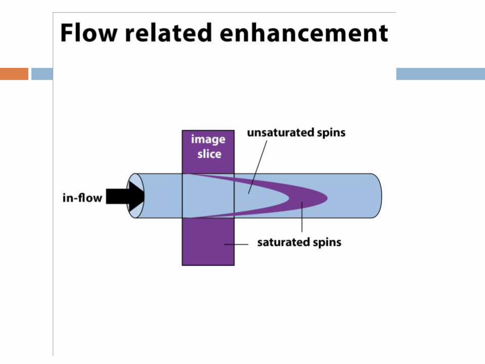
Entry slice phenomenon
When unsaturated spins in blood first enter in to
a slice or slices.
Characterized by bright signal in a blood vessel
at the first slice.
Confused with thrombosis.
Gradient echo flow techniques to differentiate.
Solution
Use spatial saturation bands before the first and
after the last.
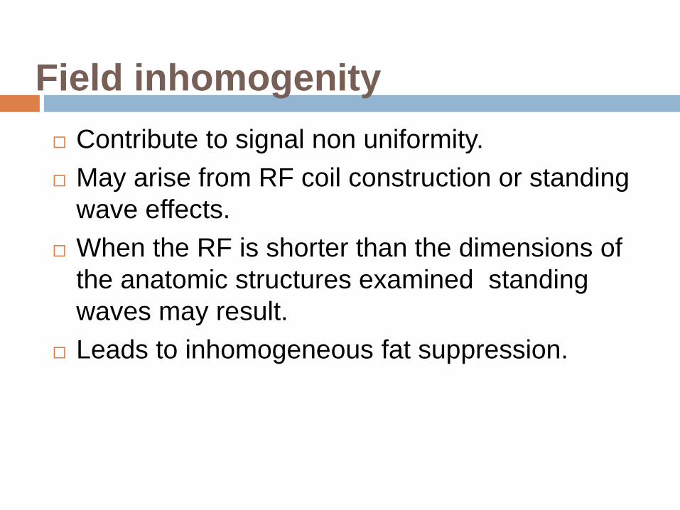
Field inhomogenity
Contribute to signal non uniformity.
May arise from RF coil construction or standing
wave effects.
When the RF is shorter than the dimensions of
the anatomic structures examined standing
waves may result.
Leads to inhomogeneous fat suppression.

Solution
Shimming –allow precise control of overall
homogeneity of RF field.
Use STIR for Fat Sat.
Coil- use volume coils, allow space between body
and coil.
Dielectric –use phased array coils.


Slice overlapping
Loss of signal due to multi slice, multi angle
acquisition or imperfect slice profile.
Mechanism : Spin saturation.
If slices at different angles cross, then spins that
have previously excited, could be excited again.
Mostly seen in spine imaging e.g. L4-L5 or L5-
S1.
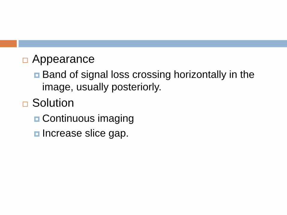
Appearance
Band of signal loss crossing horizontally in the
image, usually posteriorly.
Solution
Continuous imaging
Increase slice gap.


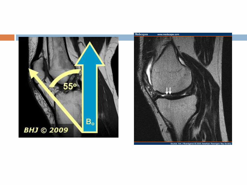
Magic angle artifact
Seen most frequently in tendons and ligaments that are oriented at a 55 degree to main magnetic field.
Normally dipolar interaction between water molecules in ligaments are strong.
Which implies that T2 relaxation is very fast leading to signal loss.
Dipolar interaction go to zero.
Solution Lengthen TE
Use T1 weighted sequences since T1 relaxation is unaffected by this.

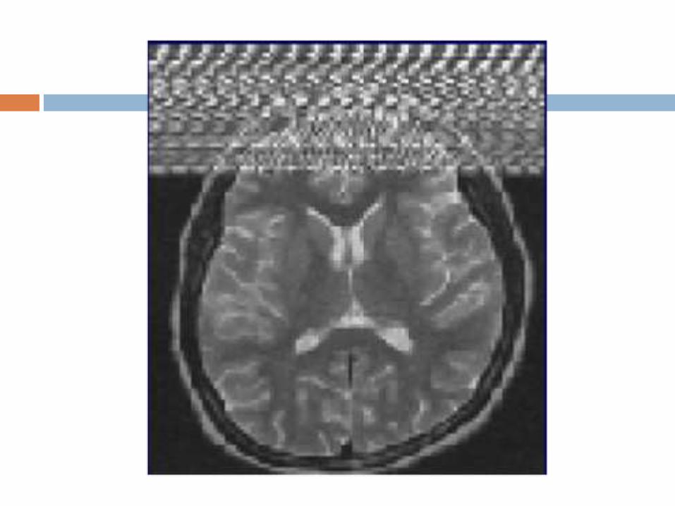
Moire fringes
An interference pattern most commonly when
doing gradient echo images.
One cause is aliasing of one side of the body to
the other results in superimposition.
Can also be caused by receiver picking up a
stimulated echo.
Similar to the effect of looking through two
window screens.

Solution
Improve shimming

RF overflow artifact
Non uniform, washed out appearance in an
image.
Occurs when the signal received from the patient
is too intense to be digitized by analog to digital
converter.
Auto prescanning usually adjusts the receiver
gain.
Post processing methods also existing but may
be time consuming.


Magnetic suscepbility artifact
Distortion in the MR image especially seen in
while imaging with metallic orthopedic hardware
or dental work.
Magnetic field inhomogenetics introduced by the
metallic object in to homogeneous magnetic
field.
Greater at high magnetic field strength.
Worst with long TE and gradient echo
sequences.

Appearance
Bright and dark areas
Solution
Larger receiver bandwidth
Gradient echo and echo planar sequences
should be avoided.
The use of echo spin particularly fast spin
echo sequences should be considered.


Eddy current artifact
Varying magnetic field induces electric current
which distort gradient waveforms.
When diffusion gradient applied, change in
magnetic field creates electric current .
Such current creates smaller magnetic field that
Bo.
Modern gradient coils equipped with active
shielding to avoid these effects of electric
conduction.

Solution
Shielding gradients.
A distorted gradient
waveform is used

Central Point artifact
A focal dot of increased or decreased signal in
the center of the image.
Caused by constant offset of the DC voltage in
the amplifiers.
Solution Requires calibration.
Maintain a constant temperature.

Zipper artifact
Most of them related to hardware or software
problems.
RF from some radio transmitters will cause
zipper that are oriented perpendicular to
frequency direction.
Occur in either frequency or phase encoding
directions.
Solutions
MR scanner room is shut down.
Remove all electric devices from patient.

Spike artifact
Caused by one bad data point k-space.
Shows one data point in k-space, which is out of
ordinary.
Diagonal lines in the image.
Solution
Repeat the scan


Annefact artifact
Due to anatomy within the active volume of the
coil, but outside the Fov.
Signals from such region give rise to ghost
imaging in the phase encoding direction.
Most commonly in sagittal spine imaging
especially in T and L spines.
Always turn off the coils which is not in use.