SPIRE Overview Bernhard Schulz, Nanyao Lu, Kevin Xu, Dave Shupe, Lijun Zhang, Arnie Schwartz
Department of Energy Office of Legacy Management
September 29, 2008
Mr. Timothy Fischer U.S. Environmental Protection Agency Region V-SRF-6J 77 W. Jackson Blvd. Chicago, IL 60604-3590
Mr. Thomas Schneider, Project Manager Ohio Environmental Protection Agency Southwest District Office 401 East Fifth Street Dayton, Ohio 45402-2911
Dear Mr. Fischerand Mr. Schneider:
Subject: Transmittal of the Response to Comments on the Fernald Preserve Visitors Center Operation and Maintenance Plan Wastewater Bio-Treatment Wetland
This letter transmits from the U.S. Department ofEnergy the response to comments on the Fernald Preserve Visitors Center Operation and Maintenance Plan for the Wastewater Bio-Treatment Wetland. The revised document is attached as well.
If you have any questions or require additional information, please call me at (513) 648-3148.
SincerelY ~, (J
J e Powell a;ernaid Preserve Manager
DOE-LM-20.1
Enclosure
2597 B 3/4 Road, Grand Junction, CO 81503 u 3600 Collins Ferry Road, Morgantown, WV 26505 626 Cochrans Mill Road, P.O. Box 10940, Pittsburgh, PA 15236 o 1000 Independence Ave., S.W., Washington, DC 20585
11025 Dover St., Suite 1000, Westminster, CO 80021 o 10995 Hamilton-Cleves Highway, Harrison, OH 45030 955 Mound Road, Miamisburg, OH 45342 o 232 Energy Way, N. Las Vegas, NV 89030
REPLY TO: Harrison Office

Mr. Timothy Fischer Mr. Thomas Schneider Page 2
cc w/enclosure: M. Cullerton, Tetra Tech. S. Helmer, ODH M.'Murphy, USEPA-V, A-18J T. Pauling, DOE (electronic) T. Schneider, OEPA (three copies of enclosure) M. Shupe, HSI GeoTrans Project Record File (thru W. Sumner) Administrative Records (thru W. Sumner)
cc w/o enclosure: . 1. Homer, Stoller
F. Johnston, Stoller M. Sizemore;Stoller

Response to Comments on the
Bio-Treatment Wetland Operation and Maintenance Plan
1. Commenting Organization: Ohio EPA Commentor: DSW Section #: Health and Safety Pg #: 1 Line #: na Code: C Comment: Prevent children and domestic animals from playing in the area to avoid contact with potentially infections microorganisms. As there will not be personnel present at the treatment wetland at all times, how will the public be kept out?
Response: Two additional "Danger - Unsafe Water" signs have been installed in front of the SSF wetland basin. Therefore, sufficient signage is in place to warn of the unsafe conditions present. In addition, site visitors are instructed to stay on trails at all times. From a maintenance and aesthetics perspective, no additional restrictions (i.e., fencing) are needed.
Action: None required.
2. Commenting Organization: Ohio EPA Commentor: DSW Section #: Septic Tanks Pg #: 6 Line #: B-1 Code: C Comment: No signage currently exists to inform people not to dispose ofpersonal hygiene products into the septic system. Ohio EPA recommends installation of such signage in the visitor center restrooms. .
Response: Agree..The requested signage has been installed.
Action: None required.
3. Commenting Organization: Ohio EPA Commentor: DSW Section #: Subsurface Flow Wetland Pg #: 8 Line #: A-3 Code: C Comment: The water level in the SSF wetland should be at or slightly above the top ofthe mulch layer until the plants have about 1-2 feet ofnew growth. During a site visit on August 11, 2008, it was observed that the water level was below the mulch layer (mulch layer appeared mostly dry), although the plants clearly do not have 1-2 feet of new growth yet. Also, yellowing of the plants was observed which corresponds to stressed vegetation.
Response: The acceptable range for SSF wetland water levels is within the three-inch mulch layer and not above it Water levels in the SSF wetland are checked at least weekly and water added as needed. In the initial weeks of operation, some fluctuation in SSF wetland water levels has occurred as operations personnel have become familiar with the amount of transpiration that is taking place ona day-to-day basis. In general, vegetation has responded well and is becoming sufficiently established across the SSF wetland.
Action: Revise the O&M Plan and associated operating procedures to make clear that optimal water levels are within the three-inch mulch layer and not above it.

4. Commenting Organization: Ohio EPA Commentor: DSW Section #: Subsurface Flow Wetland Pg #: 8 Line #: A-6 Code: C Comment: As mentioned in Comment #3, stressed vegetation was observed in the SSF on August 11, 2008. It is likely, though, that the stressed vegetation is a result of a lower water level and not due to high levels of effluent, as the Visitors Center is not open yet.
Response: See Response to Comment No.3.
Action: See Action to Comment No.3.
5. Commenting Organization: Ohio EPA Commentor: DSW Section #: Subsurface Flow Wetland Pg#: 14 Line #: H-3 Code: C Comment: This section states that the perimeter ofthe planted basin will be lined with welded wire fencing, and then strung with monofilament fishing line. On August 11, 2008, the monofilament fishing line was observed, but no welded wire fencing had been installed.
Response: Both monofilament fishing line and welded wire fencing have been used in the past as goose deterrents. From a maintenance and aesthetics perspective, it was determined to use monofilament fishing line instead ofwelded wire fencing.
Action: Revise the O&M Plan to state that monofilament fishing line is used instead ofwelded wire fencing.
6. Commenting Organization: Ohio EPA Commentor: DSW Section #: Pumps Pg #: 16 Line #: A-3 Code: C Comment: Please list the pump electrical service breaker numbers that have been omitted.
Response: Agree. The breaker numbers were not available at the time of the original O&M Plan . submittal.
Action: Revise O&M Plan to state that the electrical service breaker numbers are Breakers 2 & 4 in PanelLl'A.
OPERATIONS AND MAINTENANCE PLAN
FERNALD PRESERVE VISITOR CENTER WASTEWATER BIO-TREATMENT WETLAND
Prepared for
Sr": Stoller 10995 Hamilton-Cleves Highway Harrison, OH 45030
and
Department of Energy
August 1, 2008 Revised September 24, 2008
DRS 1375 Euclid Avenue. Suite 600 Cleveland, Ohio 44115-1808 216-622-2400'
Project No. 41785943.10000
Operation and Maintenance Manual Bio-Treatment Wetland
Fernald Preserve Visitors Center
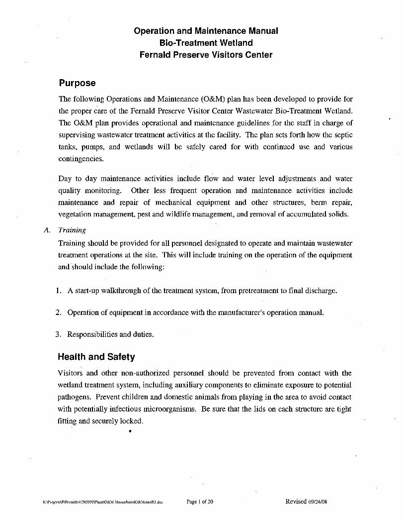
Purpose
The following Operations and Maintenance (O&M) plan has been developed to provide for
the proper care of the Fernald Preserve Visitor Center Wastewater Bio-Treatment Wetland.
The O&M plan provides operational and maintenance guidelines for the staff in charge of
supervising wastewater treatment activities at the facility. The plan sets forth how the septic
tanks, pumps, and wetlands will be safely cared for with continued use and various
contingencies.
Day to day maintenance activities include flow and water level adjustments and water
quality monitoring. Other less frequent operation and maintenance activities include
maintenance and repair of mechanical equipment and other structures, berm repair,
vegetation management, pest and wildlife management, and removal of accumulated solids.
A. Training
Training should be provided for all personnel designated to operate and maintain wastewater
treatment operations at the site. This will include training on the operation of the equipment
and should include the following:
1. A start-up walkthrough of the treatment system, from pretreatment to final discharge.
2. Operation of equipment in accordance with the manufacturer's operation manual.
3. Responsibilities and duties.
Health and Safety
Visitors and other non-authorized personnel should be prevented from contact with the
wetland treatment system, including auxiliary components to eliminate exposure to potential
pathogens. Prevent children and domestic animals from playing in the area to avoid contact
with potentially infectious microorganisms. Be sure that the lids on each structure are tight
fitting and securely locked;
•
K:\ProjeclSlF\FemaldI41785932\PlansIO&M ManuallmodO&MmanRI.doc Page 1 of 20 Revised 09124/08
Operation and Maintenance Manual Bio-Treatment Wetland
Fernald Preserve Visitors Center
Limitations
This O&M· manual has been prepared to provide general guidance and should be
supplemented by other resources as needed to ensure the safe and effective operation of the
Fernald Preserve Visitor Center wastewater treatment bio-wetland.
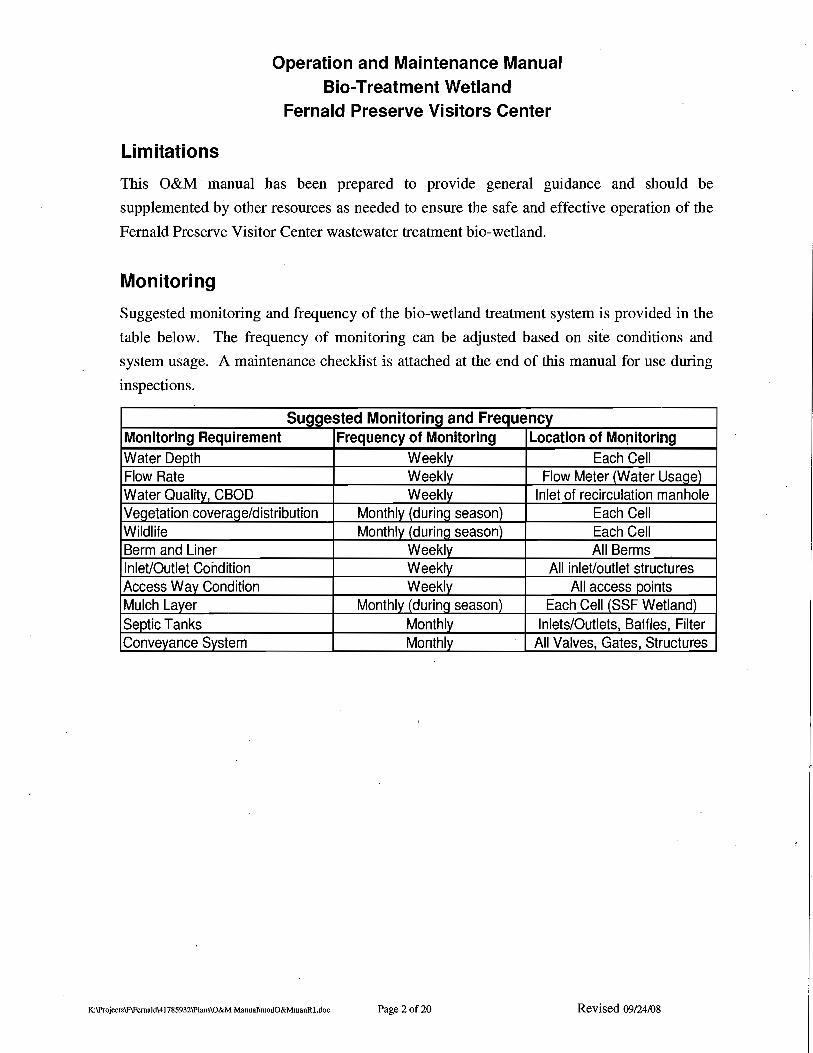
Monitoring
Suggested monitoring and frequency of the bio-wetland treatment system is provided in the
table below. The frequency of monitoring can be adjusted based on site conditions and
system usage. A maintenance checklist is attached at the end of this manual for use during
inspections.
Suggested Monitoring and Frequency Monitoring ReqUirement Frequency of Monitoring Location of Monitoring Water Depth Weekly Each Cell Flow Rate Weekly Flow Meter (WaterUsage) WaterQuality, CBOD Weekly Inlet of recirculation manhole Veoetation coveraoe/distribution Monthly (durino season) Each Cell Wildlife Monthly (durlnq season) Each Cell Berm and Liner Weekly All Berms Inlet/Outlet Condition Weekly All inlet/outlet structures Access Way Condition Weekly All access points Mulch Layer Monthly (durlnc season) Each Cell (SSF Wetland) Septic Tanks Monthly Inlets/Outlets, Baffles, Filter Conveyance System Monthly All Valves, Gates, Structures
K:lPTojecls\F\FemaldI41785932\Plans\O&M Manual\rnodO&MrnanRl.doc Page 20f20 Revised 09/24/08
Operation and Maintenance Manual Bio-Treatment Wetland
Fernald Preserve Visitors Center
Conveyance System A. Conveyance System Wastewater Flows
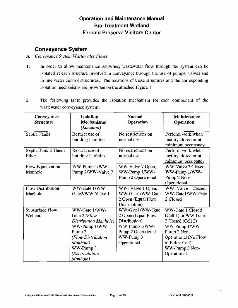
1. In order to allow maintenance activities" wastewater flow through the system can be
isolated at each structure involved in conveyance through the use of pumps, valves and
in-line water control structures. The locations of these structures and the corresponding
isolation mechanisms are provided on the attached Figure 1.
2. The following table provides the isolation mechanism for
wastewater conveyance system:
Conveyance Structure
Septic Tanks
Septic Tank Effluent Filter
Flow Equalization Manhole
Flow Distribution Manhole
Subsurface Flow Wetland
Isolation Mechanisms (Location)
Restrict use of building facilities
Restrict use of building facilities
WW-Pump I/WW-Pump 2/WW-Valve 7
WW-Gate IIWW-Gate2IWW-Valve 1
WW-Gate I/WW-Gate 2 (Flow Distribution Manhole) WW-Pump IIWW-Pump 2 (Flow Distribution Manhole) WW-Pump3 (Recirculation Manhole)
Normal Operation
No restrictions on normal use
No restrictions on normal use
WW-Valve 7 Open, WW-Pump I/WW-Pump 2 Operational
WW- Valve 1 Open, WW-GateIIWW-Gate 2 Open (Equal Flow Distribution) WW-GateIIWW-Gate 2 Open (Equal Flow Distribution) WW-Pump IIWW-Pump 2 Operational WW-Pump3 Operational
each component of the
Maintenance Operation
Perform work when facility closed or at minimum occupancy Perform work when facility closed or at minimum occupancy WW-VaIve 7 Closed, WW -Pump I/WW-Pump 2 Non-Operational WW- Valve 1 Closed, WW-GateIIWW-Gate 2 Closed
WW -Gate 1 Closed (CellI) or WW-Gate 2 Closed (Cell 2) WW-Pump I/WW-Pump 2 Non-Operational (No Flow to Either Cell) WW-Pump 3 Non-Operational
K:lProjectslFlFemaldI417859321PIansIO&M ManuallmodO&MmanRl.doc Page 3 of 20 Revised 09124/08

Operation and Maintenance Manual Bio-Treatment Wetland .
Fernald Preserve Visitors Center
Conveyance Isolation Normal Maintenance Mechanisms Operation OperationStructure (Location)
Recirculation WW-Valve 2/WW- WW-Valve 2/WW- WW-Valve 2/WW-Manhole Valve 3 Valve 3 Open Valve 3 Closed In-Line Water Level WW-Pump3 WW-Pump3 WW-Valve 2/WW-Control Structure/ WW-Valve 2/WW- OperationallWW- Valve 3 Closed IWW-
Valve 3 (SSF Wetland Valve 2lWW-Valve 3 Pump 3 Non-Effluent Lines) Open Operational
Surface Flow Wetland WW-Valve 4/WW- WW-Valve 4 Open! WW-Valve 4 Closed! Valve 5 (SF Wetland WW-Valve 5 Closed WW-Valve 5 Closed Influent Line)IWW- WW-Valve 6 Open! WW-Valve 6 Open! Valve 6IWW-WLC 2 WW-WLC2at WW-WLC 2at (SF Wetland Effluent Design Elevation(SF Lowest Elevation to Line) Wetland Effluent Drain SSF Wetland
Line) Water Level Control WW-Valve 6 (SF WW-Valve 6 Open WW-Valve 6 Closed Structure (WLC 2) Wetland Effluent
Line)
3. The above isolation mechanisms can be used in different combinations to direct or
restrict flow as needed for both normal operation and maintenance activities. For
example, to drain the SF wetland, WW-Valve 5 and WW-Valve 6 must be closed,
WW-Valve 7 open, and the SF wetland water level control structure plates raised.
Depending on the flow through the system, it may be desirable to restrict input from the
building in order to do this to avoid an overflow condition at the water level control
manhole.
4. For normal operation, the outlets from the flow distribution manhole will be open and the
slide gates will be stored in the maintenance shed. Slide gates will be used to restrict
flow to the individual SSF wetland cells as needed for maintenance purposes. WW
Valve 1 can also be used to isolate flow to both of the SSF wetland cells.
5. To perform maintenance on the pumps, the pumps should be switched off, and the power
locked out. (See section pertaining to pump operation and maintenance for lock-out/tag
out information).
K:\ProjectslFlFemaldI41785932\PlansIO&M ManuanmodO&MmanRl.doc Page 4 of 20 Revised 09/24/08
Operation and Maintenance Manual Sio-Treatment WeUand
Fernald Preserve Visitors Center
B. General Maintenance Procedures
1. All structures involved in conveyance of water through this treatment system will be
inspected monthly for clogging (i.e. water should be free flowing without signs of
obstruction) during system start-up and semi-annually thereafter. Any materials causing
clogging will be removed immediately. Any necessary repairs will be completed. If
evidence of clogging within a sewer line is discovered, the sewer will be serviced and
cleaned immediately.
2. Check all conveyance system structures monthly for leaks from joints; water dripping or
pools formed where no water should be. Repair as soon as practical to stop any leaks. If
necessary, isolate the system components as needed in order to safely complete repairs.
Resume normal operations as soon as repairs are complete.
C. Operation
1. All equipment used in the care of the wastewater treatment facility will be operated in
strict conformance with manufacturer's operating manuals, best management practices,
safety requirements, and the requirements of this plan.
K:\ProjeclslF\FemaldI41785932\Plans\O&M Manual\modO&MmanRl.doc Page 5 of 20 Revised 09/24/08
Operation and Maintenance Manual Blo-Treatment Wetland
Fernald Preserve Visitors Center
Septic Tanks A. Start Up
1. The septic tanks will be filled with clean water to ensure that they do not inadvertently
float. For two weeks, no wastewater will be allowed to enter the system. After the two
week clean water period, wastewater will be allowed to enter the system. If signs of
stressed vegetation in the wetlands appear, the volume of septic tank effluent will be
reduced [by trucking a portion of the wastewater to a Publicly Owned Treatment Works
(POTW)] and diluting with clean water until the system can acclimate.
S. Undesirable Materials
1. Materials that degrade slowly or do not settle well should not be put into the septic tank.
Coffee grounds, cooking fats, bones and other ground garbage, cigarette butts, personal
hygiene products, etc. will not be disposed in the septic system.
C. Inspection
1. The following should be inspected or monitored monthly:
a. Sludge and scum accumulation (Open tank risers and visually inspect for
accumulation).
b. Septic tank effluent filter (Open tank riser at outlet of second septic tank).
c. Inlet and outlet baffles (Open tank risers and visually inspect baffles).
D. Cleaning
1. The tanks will be cleaned annually by pumping with a vacuum truck. A licensed septic
service contractor will perform this work. All solids will be removed, but the tank should
not be washed or disinfected. The inlets, outlets, and manholes should be inspected at
this time. If repairs are required, they should be made immediately. The septic tank
effluent filter should be cleaned or replaced at this time.
2. Emptying of the tanks for cleaning should be performed during dry weather conditions.
hnmediately after tanks are cleaned, they should be filled with clean water.
K:\ProjectslF\FemaJdI4l785932IPJansIO&M ManuallmodO&MmanRJ .doc Page 6 of 20 Revised 09/24/08

Operation and Maintenance Manual Bio-Treatment Wetland
Fernald Preserve Visitors Center
3. No one should ever enter a tank without a continuous supply of fresh air. Anyone
entering the tank should be OSHA trained in confined space entry.
4. The septic tank effluent filter should be replaced more than one time per year to prevent
solids loading and maintenance problems at the influent end of the wetland.
E. Additives
1. Septic tank additives have not been shown to be beneficial to the functioning of the septic
tank and should not be used.
K:lProjects\F\Femald1417859321PIansIO&M ManuallmodO&MmanRl.doc Page 7 of 20 Revised 09124/08

Operation and Maintenance Manual Bio-Treatment Wetland
Fernald Preserve Visitors Center
Subsurface Flow Wetland A. Start-Up and Replanting
1. Prior to planting, add clean water' to the system to maintain the water level and promote
plant growth. Maintain water level during the establishment period to allow
establishment of emergent vegetation.
2. To control the water level, adjust the stacking plates on the In-Line Water Level Control
Structure (Figure 1, WLC-1).
3. The water level in the Subsurface Flow (SSF) wetland should be kept within the 3-in.
mulch layer until the plants have about 1-2 feet of new growth. Do not submerge the
leaves of the plants. When the vegetation has been properly established, the water level
can be lowered, to the final design level, which corresponds to the top of the gravel layer.
4. Do not mow the wetland.
5. Check the water levels against the water level indicator at least once per week. If
necessary, adjust the stacking plates or add clean water. See the section on water level
controls for more information on monitoring and controlling the water level in the
wetland.
6. If signs of stressed vegetation appear, such as yellowing leaves or more than 30%
dieback, the concentration of septic tank effluent can be reduced by trucking a portion of
the wastewater to a Publicly Owned Treatment Works (POTW) and adding clean water to
dilute the septic tank effluent, which will allow the plants to acclimate. Trucking of
wastewater will be completed on an as-needed basis until the SSF wetland is accepting
100% of the wastewater from the septic tanks.
I Pond water can be used in place of potable water to irrigate the wetlands, if desired.
K:lProjectslF\FemaldI417859321PIansIO&M ManuallmodO&MmanRI.doc Page 8 of20 Revised 09/24/08

Operation and Maintenance Manual Bio-Treatment Wetland
Fernald Preserve Visitors Center
7. Upon startup of the system, the discharge valves from the recirculation manhole
(WW-Valve-4 and WW-Valve-5) will be locked shut. During the first growing season,
water entering the recirculation manhole from the SSF wetland will be tested weekly for
Carbonaceous BOD (CBOD). If the effluent exceeds 15 mg/l CBOD, the water will not
be permitted to discharge to the surface flow wetland. When testing demonstrates that a
concentration of 15mg/l or less is achieved, the lock on the recirculation manhole will be
removed and the valve will be opened to allow the wastewater to discharge to the SF
wetland. Further manipulation of the SSF wetland effluent may be needed in order to
ensure the vegetation gets established in the SF wetland.
B. Water Level
1. The water level in the SSF wetland may be adjusted for multiple purposes, including
increasing the water depth so that water is in contact with the rootstock during
establishment, to fluctuate the water depth to promote greater root penetration into the
bed gravel substrate, and to increase the available hydraulic gradient.
2. The water level should not be lowered by more then 0.75 inches per week to avoid
drought stress.
3. Normal Operation - Maintain water level in the SSF wetland at the design elevation at the
top of the gravel substrate surface at the inlet end. Adjust the water level using the in-line
water level control structure by adjustment of the stacking plate system. Water Level
Indicators are provided in each treatment wetland cell for water level determination.
4. Maintain water level in bed by utilization of the recirculation pump or adding clean
water. Without flow, water in the bed will evaporate in the summer months and freeze
during severe cold months. Both extremes will damage roots and tubers over a prolonged
period. Recirculation of the wetland effluent should occur continuously.
K:lProjeclslF\FernaldI417859321PIansIO&M ManuallrnodO&MmanRl.doc Page 9 of 20 Revised 09/24/08

Operation and Maintenance Manual Bio-Treatment Wetland
Fernald Preserve Visitors Center
5. Recirculation Pump - Adjust pumping rate, float valves and water level on the
recirculation pump so that recirculation pumping does not result in wastewater surging
abovethe mulch layer. Consult the manufacturer's operations manual for the pump for
specific operation and maintenance procedures.
6. Surface Ponding - Complete the following items as required to eliminate surface
ponding:
a. Lower the level of the outlet control structure. If no noticeable change takes place
at the influent end, the bed is likely clogged.
b. Ensure the outlet septic tank baffle is in place. Ensure that excess solids have not
accumulated in the septic tanks.
c. Check surge capacity of tank baffles to ensure scum is not escaping from the tank.
Install or replace as needed.
d. Determine if solids are accumulating in inlet distribution system. If solids have
accumulated, flush with fresh water.
, e. Determine if solids are accumulating in the effluent discharge system. If solids
have accumulated, flush with fresh water.
f. Identify and implement actions to prevent the problem from reoccurring, such as
pumping the solids from the septic tank more frequently, installation/replacement
of a septic effluent filter, or installation of an additional septic tank in series, and
elimination of any chemicals (chlorine bleach, drain cleaners, etc) that have the
potential to upset the septic tank.
g. If cleaning the inlet distributor reveals little or no solids build up in the pipe,
reduce the flow through the cell by reducing the gallons per minute pumped by
the recirculation pump.
K:lProjects\F\FemaldI417859321PIans\O&M ManuallmodO&MmanR I.doc Page 10 of 20 Revised 09/24/08
Operation and Maintenance Manual Blo-Treatment WeUand
Fernald Preserve Visitors Center
h. Water levels may temporarily increase due to flow surges. Do not make major
corrections unless water levels remain above the mulch layer for more than a
couple days.
i. Should the bed in the SSF wetland prove to be clogged, the gravel substrate may
need to be removed, cleaned and replaced and the vegetation replanted. In
extreme cases, replacement with coarser gravel substrate may be helpful.
C. Inlet Structure
1. Check inlet structure to ensure it is not totally or partially blocked by solids, algae, or
other items. Flush solids out with fresh water. Remove any articles that may block the
inlet structure.
2. If inlet structure tends to freeze during the winter months, cover with an additional
protective layer of mulch.
D. Outlet Structure
1. Check the outlet structure to ensure that it is not totally or partially blocked by solids,
algae, or other items. Flush solids out if needed. Remove any articles that may block the
effluent.
2. If outlet tends to freeze during the winter months, cover with a protective layer of mulch
or straw bales.
E. Liner
1. Check to ensure that the geomembrane liner is covered by either the gravel of the
treatment wetland bed, or soil cover.
2. Periodically check the liner for leaks around inlet structures. If necessary, drain cell,
remove gravel in suspected leak area, and patch liner following manufacturer's
directions.
K:\ProjeclslF\Pemald\41785932\Plans\O&M Manual\modO&MmanR l.doc Page 11 of20 Revised 09124/08

Operation and Maintenance Manual Blo-Treatment We'lland
Fernald Preserve Visitors Center
F. Vegetation Management
1. Check the vegetation for signs of disease or other stress (yellowing or browning,
withering, spots, etc.). Some of these symptoms may occur naturally as the plants
mature, especially after seeds have matured. If the water level in the treatment wetland
cell is satisfactory, obtain guidance from a local nursery or agricultural center.
2. Do not remove mature wetland vegetation in the fall after plants have browned. This
vegetation forms an insulating blanket for the wetland during the winter months. Do not
mow the wetland.
3. A mulch layer of approximately 3-inch thickness (including decaying plant litter) should
be maintained to protect the SSF wetland over the winter months, when the temperature
is frequently below freezing. Additional well composted weed-free mulch may be added
if needed. This insulation must be checked for degradation and maintained on an annual
basis. Effluent quality should also be checked as an indicator of insulation layer
degradation.
4. If insects are causing significant damage to the plants, obtain guidance from a local
nursery or agricultural center. Avoid the use of chemical pesticides whenever possible.
5. If vegetation does not seem healthy and water levels are correctly maintained, consult
with a local nursery to determine possible causes and courses of action.
6. Replace dead plants as necessary to fill voids. The extent of vegetative cover in the SSF
wetland following one growing season will be evaluated. Additional plugging and
planting of root stock may be conducted in the spring of 2009. Proposed species are
provided in the following table.
Common Name Plant Species
Blue Flag Iris Iris versicolor
Green Bulrush Scirpus atrovirens
Duck Potato Saaittaria latifolia
River Bulrush Scirpus fluviatilis
Prairie Cordgrass Sosrtlns pectinata
K:lProject,\F\FemaldI417859321PIan,IO&M ManuanmodO&MmanRl.doc Page 12 of20 Revised 09124/08

Operation and Maintenance Manual Sio-Treatment Wetland'
Fernald Preserve Visitors Center
7. Use at least three different species of rootstock when planting SSF wetland. At least 60%
of rootstock should be Scirpus atrovirens (Green Bulrush). Plants should be spaced 2
feet by 2-feet (4 square feet per plant) maximum. Rootstock in the form of tubers should
be at least 5/8-inch in diameter. Rootstock in the form of rhizomes should be at least 2
inches long. Duck Potato rootstock will be in the form of tubers at least 5/8-inch in
diameter. Blue Flag Iris rootstock in the form of rhizomes should be at least 2 inches
long. Green Bulrush, River Bulrush, and Prairie Cordgrass should be in the form of root
wads. Bodies and shoots associated with rootstock should be rigid to the touch. Bodies
and shoots that are soft, mushy and appear rotten or decomposed should not be utilized.
Established root stock should contain roots that are rigid to the touch. Tubers and
rhizomes should be white in appearance. To' plant stock, hand-dig through the mulch
layer and SSP wetland gravel substrate. Stock should be planted directly into gravel
substrate.
8. Pull up volunteer weeds, trees, and shrubs from the wetland. These species will shade
and crowd the desirable wetland species. Use spot application of appropriate herbicide if
necessary. Consult with a local nursery to determine appropriate chemical use,
considering water quality objective of the treatment system.
9. Prevent excessive shading of the wetland vegetation by controlling the growth of trees or
high shrubs near the treatment wetland cells. Most wetland species need a minimum of
six hours of sunlight per day. i
10. Deep Root Growth (to be completed in the fall whenever new plantings have occurred):
a. Encourage deep root growth by lowering the water level over several weeks
during a dormant period. Drop water levels gradually in order to encourage plant
growth.
K:lProjects\F\FernaldI417859321PIansIO&M MannaIlrnodO&MmanRl.dnc Page 13 of 20 Revised 09/24/08
Operation and Maintenance Manual Sio-Treatment Wetland
Fernald Preserve Visitors Center
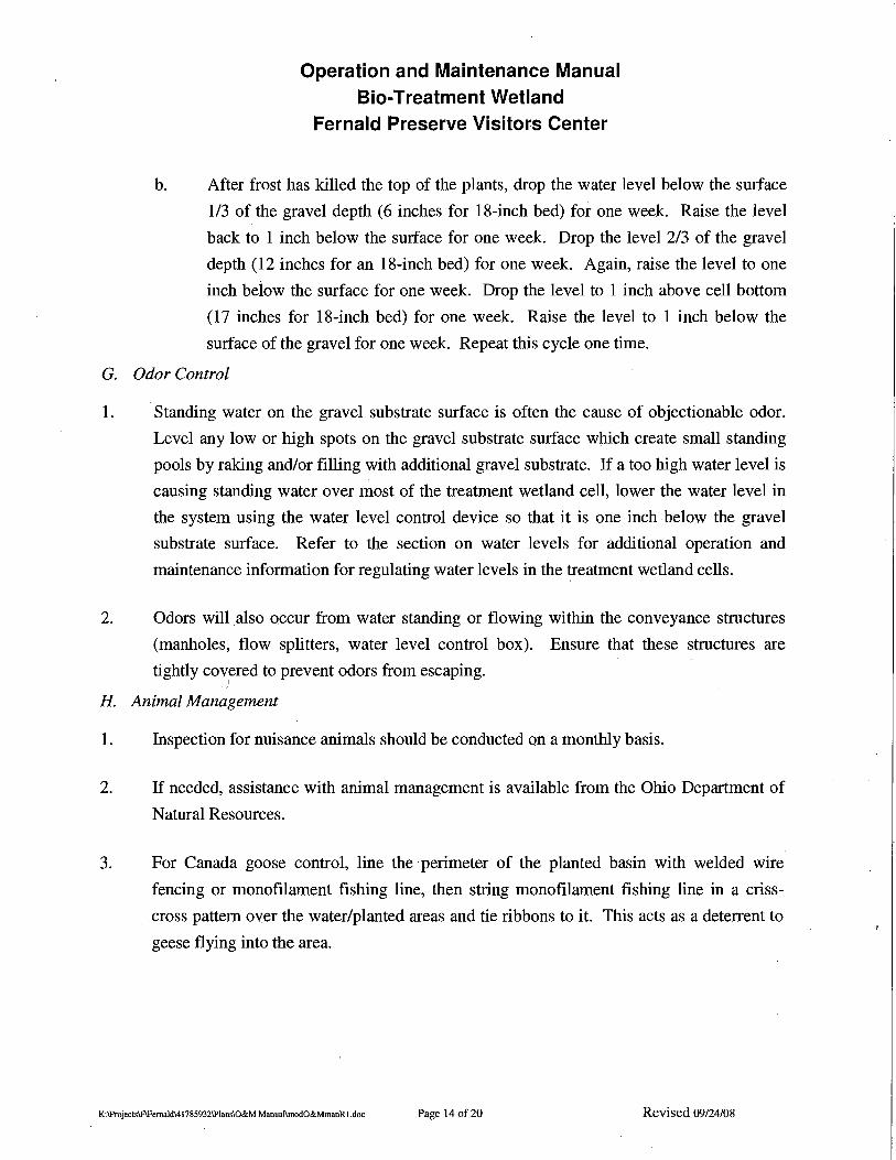
b. After frost has killed the top of the plants, drop the water level below the surface
1/3 of the gravel depth (6 inches for l8-inch bed) for one week. Raise the level
back to 1 inch below the surface for one week. Drop the level 2/3 of the gravel
depth (12 inches for an l8-inch bed) for one week. Again, raise the level to one
inch below the surface for one week. Drop the level to 1 inch above cell bottom
(17 inches for l8-inch bed) for one week. Raise the level to 1 inch below the
surface of the gravel for one week. Repeat this cycle one time.
G. Odor Control
1. Standing water on the gravel substrate surface is often the cause of objectionable odor.
Level any low or high spots on the gravel substrate surface which create small standing
pools by raking and/or filling with additional gravel substrate. If a too high water level is
causing standing water over most of the treatment wetland cell, lower the water level in
the system using the water level control device so that it is one inch below the gravel
substrate surface. Refer to the section on water levels for additional operation and
maintenance information for regulating water levels in the treatment wetland cells.
2. Odors will also occur from water standing or flowing within the conveyance structures
(manholes, flow splitters, water level control box). Ensure that these structures are
tightly covered to prevent odors from escaping. I
H. Animal Management
1. Inspection for nuisance animals should be conducted on a monthly basis.
2. If needed, assistance with animal management is available from the Ohio Department of
Natural Resources.
3. For Canada goose control, line the perimeter of the planted basin with welded wire
fencing or monofilament fishing line, then string monofilament fishing line in a criss
cross pattern over the water/planted areas and tie ribbons to it. This acts as a deterrent to
geese flying into the area.
K:lProjects\F\FemaldI417859321PIansIO&M ManuaIlmodO&MmanRl.doc Page 140£20 Revised 09124/08
Operation and Maintenance Manual Bio-Treatment Wetland
Fernald Preserve Visitors Center
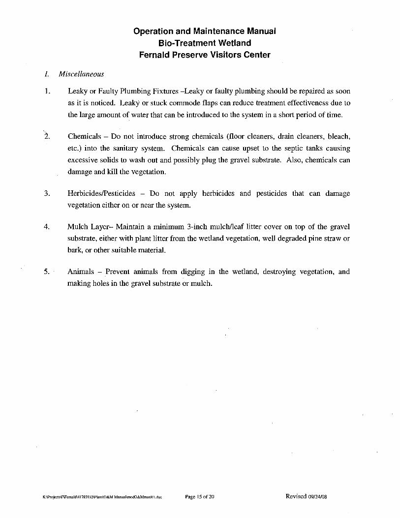
1. Miscellaneous
1. Leaky or Faulty Plumbing Fixtures -Leaky or faulty plumbing should be repaired as soon
as it is noticed. Leaky or stuck commode flaps can reduce treatment effectiveness due to
the large amount of water that can be introduced to the system in a short period of time.
'2. Chemicals - Do not introduce strong chemicals (floor cleaners, drain cleaners, bleach,
etc.) into the sanitary system. Chemicals can cause upset to the septic tanks causing
excessive solids to wash out and possibly plug the gravel substrate. Also, chemicals can
damage and kill the vegetation.
3. HerbicideslPesticides - Do not apply herbicides and pesticides that can damage
vegetation either on or near the system.
4. Mulch Layer- Maintain a minimum 3-inch mulchlleaf litter cover on top of the gravel
substrate, either with plant litter from the wetland vegetation, well degraded pine straw or
bark, or other suitable material.
5. Animals - Prevent animals from digging in the wetland, destroying vegetation, and
making holes in the gravel substrate or mulch.
K:\ProjeclslF\FemaldI417859321PIansIO&M ManuanmodO&MmanRl.doc Page 15 of20 Revised 09/24/08
Operation and Maintenance Manual Bio-Treatment Wetland
Fernald Preserve Visitors Center
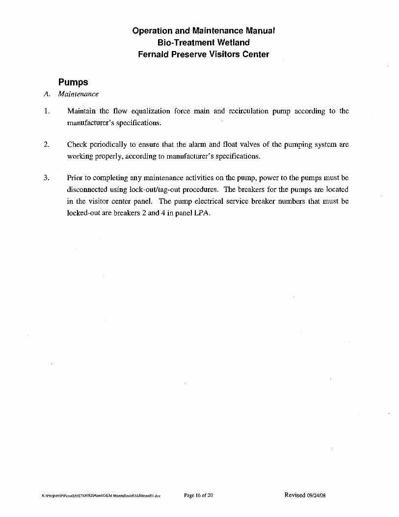
Pumps A. Maintenance
1. Maintain the flow equalization force main and recirculation pump according to the
manufacturer's specifications.
2. Check periodically to ensure that the alarm and float valves of the pumping system are
working properly, according to manufacturer's specifications.
3. Prior to completing any maintenance activities on the pump, power to the pumps must be
disconnected using lock-out/tag-out procedures. The breakers for the pumps are located
in the visitor center panel. The pump electrical service breaker numbers that must be
locked-out are breakers 2 and 4 in panel LPA.
K:\ProjeclslF\FemaldI417859321PIansIO&M ManuallmodO&MmanRl.doc Page 16 of 20 Revised 09/24/08
Operation and Maintenance Manual Sio-Treatment Wetland
Fernald Preserve Visitors Center
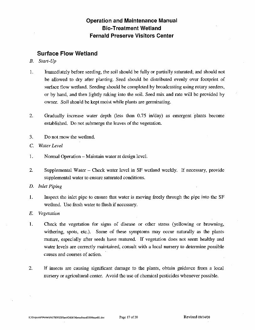
Surface Flow Wetland B. Start-Up
1. hnmediately before seeding, the soil should be fully or partially saturated; and should not
be allowed to dry after planting. Seed should be distributed evenly over footprint of
surface flow wetland. Seeding should be completed by broadcasting using rotary seeders,
or by hand, and then lightly raking into the soil. Seed mix and rate will be provided by
owner. Soil should be kept moist while plants are germinating.
2. Gradually increase water depth (less than 0.75 in/day) as emergent plants become
established. Do not submerge the leaves of the vegetation.
3. Do not mow the wetland.
C. Water Level
1. Normal Operation - Maintain water at design level.
2. Supplemental Water - Check water level in SF wetland weekly. If necessary, provide
supplemental water to ensure saturated conditions.
D. Inlet Piping
1. Inspect the inlet pipe to ensure that water is moving freely through the pipe into the SF
wetland. Use fresh water to flush if necessary.
E. Vegetation
1. Check the vegetation for signs of disease or other stress (yellowing or browning,
withering, spots, etc.). Some of these symptoms may occur naturally as the plants
mature, especially after seeds have matured. If vegetation does not seem healthy and
water levels are correctly maintained, consult with a local nursery to determine possible
causes and courses of action.
2. If insects are causing significant damage to the plants, obtain guidance from a local
nursery or agricultural center. Avoid the use of chemical pesticides whenever possible.
K:\ProjeclslF\FemilldI417859321PIansIO&M ManuanmodO&MmanRl.doc Page 17 of 20 Revised 09124/08

Operation and Maintenance Manual Bio-Treatment Wetland
Fernald Preserve Visitors Center
3. Replanting of the SF wetland may be desirable if large algal blooms appear on the water.
surface. In this case, the water should be lowered to expose the root media and to allow
the algae mats to decay prior to replanting.
4. Invasive plant species may appear in the wetland if there is excess plant detritus on the
surface of the wetland. These species should be removed by hand weeding and spot
application of appropriate herbicides.
5. Controlled burning can also be used as an invasive species management tool. The
burning should be limited to every 5 years in late fall or early winter, and the bum area
should be isolated with fire breaks such as: areas of no vegetation, gravel, or water filled
ditches and not be used for a month after burning; with influent directed to other areas
during this time. Notification and coordination with the local fire department will likely
be required.
.6. Do not remove mature wetland vegetation in the fall after plants have browned. This
vegetation forms an insulating blanket for the wetland during the winter months. Do not
mow the wetland.
7. Black willow cuttings will be planted around the SF wetland. Inspection of black willow
saplings and trees will continue on a monthly basis with replanting as necessary. Black
willow saplings can be protected from the threat posed by beavers by using a heavy wire
mesh and heavy gauge hardware cloth of tar paper wrapped to 3ft high.
F. Animal Management
1. Inspection for nuisance animals should be conducted on a monthly basis.
2. Assistance with animal management is available from the Ohio Department of Natural
Resources.
3. For Canada goose control, line the perimeter of the planted basin with welded wire
fencing, then string monofilament fishing line in a criss-cross pattern over the
water/planted areas and tie ribbons to it. This acts as a deterrent to geese flying into the
area.
K:\Projecls\F\FemaId\41785932\Plans\O&M Manual\modO&MmanRl.doc Page 18 of20 Revised 09/24/08
Operation and Maintenance Manual Bio-Treatment Wetland
Fernald Preserve Visitors Center
Berms/Ditches A. Maintenance
1. Repair any earthen berm erosion as soon as itis noted.
2. Repair leaks around the berms as soon as they are noted by plugging or sealing, etc.
B. Vegetation Management
1. Trim/remove vegetation as required to ensure access to the wetland, integrity of the berm,
and aesthetics of the area.
2. Seeded ditches and berms should be inspected between 6 to 12 months after seeding to
ensure at least 70% coverage of the area. If any area is not at least 70% covered with
established vegetation, that area should be reseeded, and checked again within 6 to 12
months.
3. Inspection of the ditches and berms is necessary on a monthly basis during the growing
season after the period of initial planting. Normally eroded or other damaged areas
should be reseeded as discussed above, and in accordancewith ODOT item 659.23 using
the seed mix provided below.
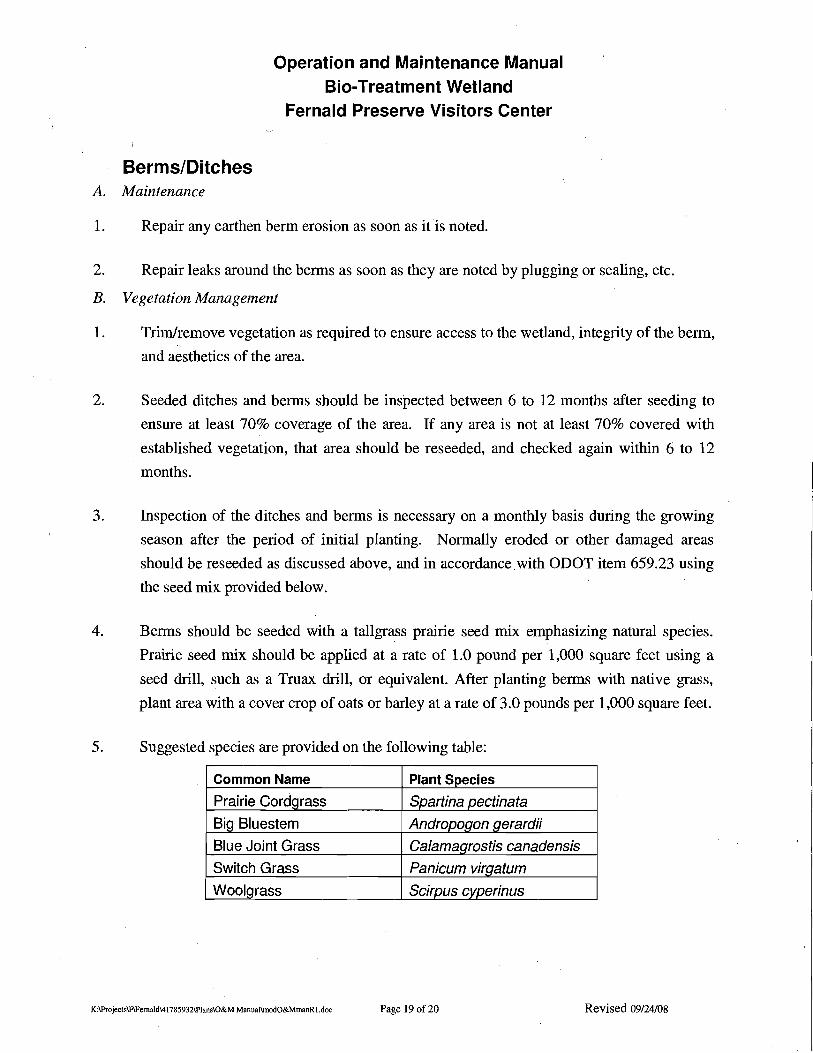
4. Berms should be seeded with a tallgrass prairie seed mix emphasizing natural species.
Prairie seed mix should be applied at a rate of 1.0 pound per 1,000 square feet using a
seed drill, such as a Truax drill, or equivalent. After planting berms with native grass,
plant area with a cover crop of oats or barley at a rate of 3.0 pounds per 1,000 square feet.
5. Suggested species are provided on the following table:
Common Name
Prairie Cordgrass
BiQ Bluestem
Blue Joint Grass
Switch Grass
Wooigrass
Plant Species
Spartina oectinete
Andropoqon gerardii
Calamagrostis canadensis
Panicum viraetum Scirpus cvoerinus
K:lProjectslF\Femald\417859321PIans\O&M Manual\modO&MmanRl.doc Page 190£20 Revised 09/24/08

Operation and Maintenance Manual Blo-Treatment Wetland
Fernald Preserve Visitors Center
Emergency Spillway/SF Wetland Effluent Monitoring
1. The emergency spillway/SF wetland effluent monitoring will be covered under the
general site NPDES permit for the Fernald Preserve Visitor's Center. The modification
to the permit will include monitoring limits for the spillway and schedule of testing, and
will be included in this plan at a later date.
K:lProjecls\F\FemaldI41785932\PlansIO&M ManuallmodO&MmanR I.doc Page 20 of 20 Revised 09/24/08

FORMS
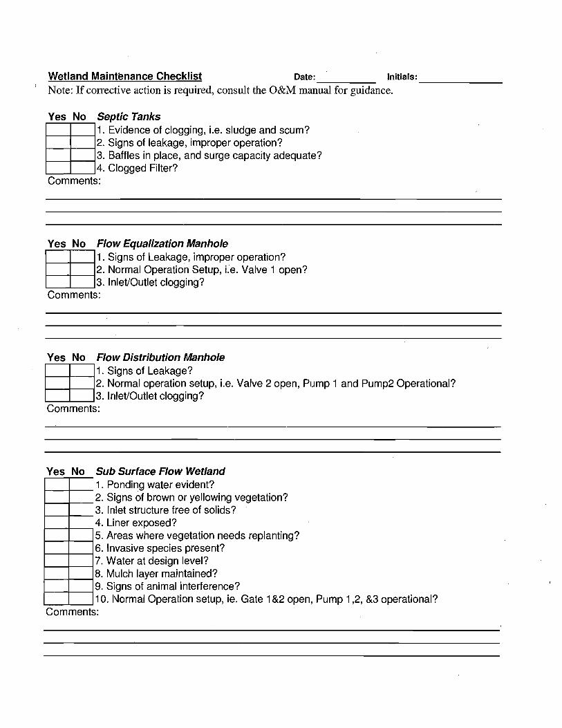
-------Wetland Maintt!nance Checklist Date: Initials:
Note: If corrective action is required, consult the O&M manual for guidance.
Yes No Septic Tanks 1. Evidence of clogging, i.e. sludge and scum?
m2. Signs of leakage, improper operation? 3. Baffles in place, and surge capacity adequate? 4. Clogged Filter?
Comments:
Yes No Flow Equalization Manhole
rn1. Signs of Leakage, improper operation? 2. Normal Operation Setup, i.e. Valve 1 open? 3. Inlet/Outlet clogging?
Comments:
Yes No Flow Distribution Manhole
rn1. Signs of Leakage? 2. Normal operation setup, i.e. Valve 2 open, Pump 1 and Pump2 Operational? 3. Inlet/Outlet clogging?
Comments:
Yes No Sub Surface Flow Wetland 1---+_...., 1. Ponding water evident? 1---+_....,2. Signs of brown or yellowing vegetation?
3. Inlet structure free of solids? ~--+-....,
1----+----i4. Liner exposed? 1---+_---15. Areas where vegetation needs replanting? 1----+----i6. Invasive species present? 1----+_---i7. Water at design level? 1---+_---18. Mulch layer maintained? 1---+----i9. Signs of animal interference? '----'-_--' 1O. Normal Operation setup, ie. Gate 1&2 open, Pump 1,2, &3 operational? Comments:
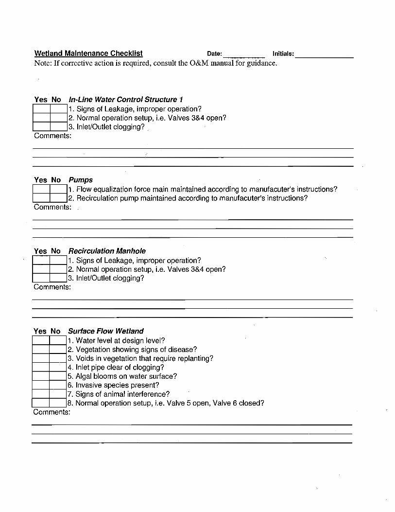
-------Wetland Maintenance Checklist Date: Initials:
Note: If corrective action is required, consult the O&M manual for guidance.
Yes No In-Line WaterControlStructure 1
rn1. Signs of Leakage, improper operation? 2. Normal operation setup, i.e. Valves 3&4 open? 3. Inlet/Outlet clogging?
Comments:
Yes No Pumps
EE1. Flow equalization force main maintained according to manufacuter's instructions? 2. Recirculation pump maintained according to manufacuter's instructions?
Comments:
Yes No Recirculation Manhole
rn1. Signs of Leakage, improper operation? 2. Normal operation setup, l.e. Valves 3&4 open? 3. Inlet/Outlet clogging?
Comments:
Yes No SurfaceFlow Wetland 1----+_--l1. Water level at design level?
2. Vegetation showing signs of disease? I----+---i 1----+_--l3. Voids in vegetation that require replanting? 1----+_--l4. Inlet pipe clear of clogging? 1----+_--i5. Algal blooms on water surface? 1----+---l6. Invasive species present?
7. Signs of animal interference? I----+---i '-------'-_--'8. Normal operation setup, l.e, Valve 5 open, Valve 6 closed? Comments:

-------
--------------
-------
Wetland Maintenance Checklist Date: Initials:
Note: If corrective action is required, consult the O&M manual for guidance.
Yes No Berms/Ditches
I---t----i 1. Mowing necessary? 1---t----i2. Evidence of burrowing animals? 1----+---i3. At least 70% vegetation coverage maintained?
I----+---i4. Evidence of erosion? 5. Evidence of leaks around berms?
'----------'-----'
Comments:
Yes No In-Line Water Level Control Structure 2
rn1. Signs of Leakage? . 2. Normal operation setup, Le. Valve 7 closed? 3. Inlet/Outlet clogging?
Comments:
Water L'evel Measurements SSF Cell 1 _ SSF Cell 2
SF Wetland
Flow Rate (gpm)
Sampling Yes NoCI:::::JSamples Collected?
Location: Analysis: __---'- _
Corrective Action NeededlTaken

FIGURES

j
j
j
j
j
j
j
j
j
j
j
j
j
j
j
j
j
j
j
j
j
j
j
j
j
j
j
j
j
j
j
j
j
j
j
j
j
j
jjjjjjj
j
j
j
j
jjjjjjjj
Ijj
jj j
j
j
j
j
j
j
j
Pump Installation and Service Manual
SHEF30 Submersible Pump/Effluent Pump
<I
(!HYDROM~
NOTE! To the installer: Please. make sure you provide this manual to the owner of the pumping equipment or to '. Pentairthe responsible partywho maintains the system.
Pump Group
General Information
Thank you for purchasing your HYDROMATIC pump. To help ensure years of trouble-free operation, please read the following manual carefully.
Before Operation: Read the following instructions carefully. Reasonable care and safe methods should be practiced. Check local codes and requirements before installation.
Attention:
This manual contains important information for the safe use of this product. Read this manual completely before using this product and refer to it often for continued safe product use. DO NOT THROW AWAY OR ~OSE THIS MANUAL. Keep it m a safe place so that you may refer to it often. .
WARNING: Before handling these pumps and controls . ' always disconnect the power first. .Do not smoke or use sparkable electrical devices or flames in a septic (gaseous) or possible septic sump. '
Pump Warning
1b reduce risk of electrical shock:
I. Risk of Electrical Shock: This pump has not been investigated for use in swimming pool areas.
2. Risk of Electrical Shock: Connect only to a properly grounded receptacle.
Septic tank is to be vented in accordance with local plumbing codes.
Do not smoke or use sparkable electrical devices or flame in a septic (gaseous) or possible septic sump.
If a septic sump condition may exist and if entry into sump is necessary, then (1) provide proper safety precautions per OSHA requirements and (2) do not enter sump until these precautions are strictly adhered to.
Do not install pump in location classified as hazardous per N.E.C., ANSIINFPA 70 - 1999.
Failure to heed above cautions could result in injury or death.
Installation Instructions
.These important instructions must be followed for satisfactory performance of your pUDlp. Before installation, check your local electrical and plumbing codes.
I. Provide proper sump
Minimum Sump Diameter
SHEF30 18"
Approx. Tuin~On & -Off Level
SHEF30 On 9-112" Off 3-112"
2. Make sure float (automatic models) hangs free. It should not come into contact with side or bottom of sump pit.
3. Make sure sump is free of string, cloth, nails, gravel, etc. before installing pump.
4. Do not set pump directly on
the bottom of sump if it is not solid. Raise the pump by placing bricks or concrete blocks underneath it.
5. Use steel or plastic pipe for all connecting lines between pump and sewer outlet
NOTE: Some city regulations do not allow installing a pump with plastic pipe. Check local regulations. .
6. HYDROMATIC check valve should be installed in discharge pipe, at least twelve inches above the discharge outlet of the pump. Install check valve with arrow pointing in the direction of flow.
7. A shutoff valve should also be used.
8. Connect to power source using 3~prong grounded 115 volt AC receptacle. Do not remove ground pin from electrical plug. Do not use an extension cord.
9. For proper automatic operation make sure the pump power cord is plugged into the back of the "piggyback" receptacle on the switch cord. Also ensure that the piggyback plug is securely plugged into the 115 volt grounded receptacle.
lO.lf shutoff valve is used in the discharge line, ensure that the valve is open.
11.To ensure that the pump is properly installed, fill basin with enough water to activate pump (see #1-Tum-on and -off levels). Allow pump to go through several on-off cycles to assure satisfactory operation.
12.Use pump submerged for pumping waterlike liquids (temperature to 120°F).
2
CAUTION: Do not pump flammable liquids, strong chemicals or salt water.
13.ln applications where the pump may sit idle for months at a time, it is recommended that the pump(s) be cycled every few months to ensure the pumping system is working
.properly when needed.
14.An audible alarm, such as the Hydromatic Q~Alert for high water conditions, should be installed for additional protection against high water conditions.
NOTE: The Q-Alert alarm panel is for indoor use only. For applications and product information, contact your HYDROMATIC distributor.
Your pump warranty is void...
If... power cord has been cut.
If. .. pump has been used to pump mud, cement, tar, abrasives or chemicals.
If... pump bas been used for pumping of hot water (above 120°F).
If... pump has been dismantled by other than authorized HYDROMATIC service center or distributor.
Pump Troubleshooting
Servicing should be performed only by an authorized HYDROMATIC service center.
WARNING: Always disconnect the pump from power source before handling or making any adjustments. Always wear rubber boots when there is water on the floor and you must unplug the pump or make any adjustments.
NOTE: Automatic thermal overload protects the sealed-inoil motor. Running dry may overheat the motor and activate the overload protector until the unit cools.
Pump does not run or justhums,
1. Line circuit breaker may be off, or fuse may be blown or loose. .
2. Water level in sump may be too low to activate automatic switch. See installation for proper on/off levels.
3. Pump and/or switch cord plug may not be making contact in receptacle. .
4. If pump is using the series (piggyback) cord plug, the two plugs may not be plugged together tightly.
5. Float may be stuck. Be sure float operates freely in basin.
6. If the unit is being operated by the optional float control switch, unplug the pump from the piggyback receptacle and plug the pump directly into the power source. If the pump starts each time it is plugged directly into the receptacle and does not start each time when plugged into the piggyback switch with the float raised up to a start position, replace the complete piggyback switch assembly and retest with new assembly.
7. If all symptoms check OK, motor winding may be open;
take to authorized service center for check.
Pump runs but does not deliver water.
1. Check valve may be installed backward. Arrow on valve points in direction of flow.
2. Discharge shutoff valve, if used, may be closed.
3. Pump may be air locked. Start and stop several times by plugging and unplugging cord. HYDROMATIC pumps have a small air vent bole in the impeller cavity to let out trapped air. If this hole becomes plugged, pump may air lock. To break the air lock, use a small screwdriver to clear hole in· the impeller cavity.
As a secondary precaution in installations of this type 1116" hole should be drilled in the discharge pipe below the check valve. The check valve should be 12 to 18 inches above pump discharge. Do not put check valve directly into primp .discharge opening.
NOTE: In sumps where the pump is operating daily, air locking rarely occurs.
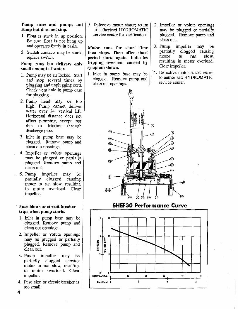
4. Pump head may be too high. Pump, cannot deliver water over 24' vertical lift. Horizontal distance does not affect pumping;' except for friction loss through the pipe.
5. Inlet in pump base may be clogged. Remove pump and clean out openings.
6. Impeller or volute openings may be plugged or partially plugged. Remove pump and clean out.
3
Pump runs and pumps out sump but does not stop. 1. Float is stuck in up position.
Be sure float is not hung up and operates freely in basin.
2. Switch contacts may be stuck; replace switch.
Pump' runs but delivers only small amount of water. 1. Pump may be air locked. Start
and stop several times by plugging and unplugging cord. Check vent hole in pump case for plugging.
2. Pump head may be too high. Pump cannot deliver water over 24' vertical lift. Horizontal distance. does not affect pumping, except loss due to friction' through discharge pipe.
3. Inlet in pump base may be clogged. Remove pump and clean out openings.
4. Impeller or volute openings may be plugged or partially plugged. Remove pump and clean out.
S. Pump impeller may be partially clogged causing motor to run slow, resulting in motor overload. Clear impeller.
Fuse blows or circuit breaker trips when pump starts.
1. Inlet in pump base may be clogged. Remove pump and clean out openings.
2. Impeller or volute openings may be plugged or partially plugged. Remove pump and clean out.
3. Pump impeller may be partially clogged causing motor to run slow, resulting in motor overload. Clear impeller.
4~ Fuse size or circuit breaker is too small.
5. Defective motor stator; return to authorized HYDROMATIC service center for verification.
Motor runs for short time then stops. Then after short period starts again. Indicates tripping overload caused by symptom shown. .
1. Inlet in pump base may be clogged. Remove pump and clean out openings.
2. Impeller or volute openings may be plugged or partially plugged. Remove pump and clean out.
3. Pump impeller may be partially clogged causing motor to run slow, resulting in motor overload. Clear impeller.
.4. Defective motor stator: return to authorized HYDROMATIC service center.
SHEF30 Performance Curve
30
'1'-~
20 -...Ii! ........... ..........
ig I':ll=' <,
3 - 10 <, ~
~.
o 0 CDpodly-lJ.S. Ii...M. 0 10 20 30 so
II--------l------+-------I Iit~ond Q
4
Pump Notes
5
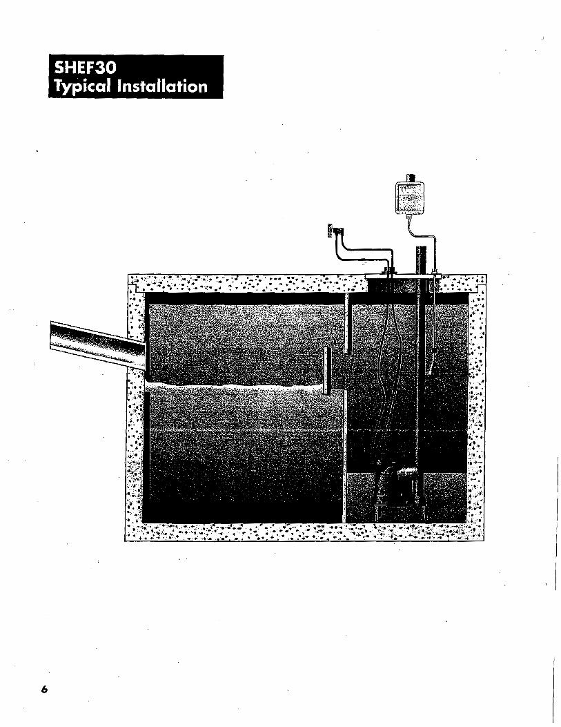
SHEF30 Typical Installation
6

SHEF30 Parts List
2fr---:--__-N
.J
it
Ref. No. Part No. Descriplion Qly. Ref. No. ParI No. Destripllon Qly.
I IOI93-ll19·1 Tag,WolTonly 1 \7 5484-00\·\ Sea!-SIDlionary \ 2 8S22·0W·1 Ring·Handle \ \8 5484·1103·1 Sea~ROlq'ing 1 3 \498\·00\·\ Plug.Pipe 1 19 14076·000·2 Plale·Seal 1 4 13424-0\3·1 label·Hydromatic \ 20 lmo.oO\·1 Screw·Quodrex #8·32 x5/16 1 5 5617-001-1 Oil \ 2\ 6000-053·\ Wire W/Terrninal I 6 8507·202-\ Volute/Molor Hou~ng I 22 139·014·\ Ring·Seal I 7 14SB\-llDl-l Stator .3HP, 115 Von, 60Hz, \ Phase \ 23 75·005-\ Nul·(ard \ 8 145·00\·) Strew·Mach [Kex Headl 2 24 \3425-064-1 Nameplafe 1 y B34-030-1 O.Ring I 25 \4623-010-\ (orn.Power 20' I
10 8521-1)01-1 Plale-Boltom 1 ~ 14623-0%0·1 (ord-Power 30' 1 11 14776-002-1 Suew·Quadrex #l().24 x1.25 3 \2 14770-005-\ Screw·Quodrex#lll-24 x.63 6 FOR AUTOMATIC OPERATION 13 8498·003·\ Impener \ NOT SHOWN 5583-001-\ Saew-Moch. {Pan Headl \ \4 14770-006·\ SlTew-Quadrex #10·24 x.38 2 \055-000·\ ne·Wlre 1 15 14581·210-1 RolorISha!l(Bearing Assembly \ MOl SHOWN 139£7-020·\ Swltch-Mech. Wide An~e 20' I 16 13507;{)01-\ Leg 3 \3967.f130-1 Swilch-Meth. Wide Angle 30' \
7
WARRANTY Hydromatic Pumps warrants to the original purchaser of each Hydromatic Pump product(s) that any part thereof which proves to be defective in material or workmanship within one year from date of installation . or 18 months from manufacture date, whichever comes first, will be replaced at no charge with a new or remanufactured part, EO.B. factory. Purchaser shall assume all responsibility and expense for removal, reinstallation and freight. Any iiem(s) designated as manufactured by others shall be covered only by the express warranty of the manufacturer thereof. This warranty does not apply to damage resulting from accident, alteration, design misuse or abuse. '
If the material furnished to the Buyer shall fail to conform to this contract or to any of the terms of this written warranty, Hydromatic Pump shall replace such nonconforming material at the original point of delivery and shall furnish instruction for its disposition. Any transportation charges involved in such disposition shall be for the Buyer's account. The Buyer's exclusive and sole remedy on account or in respect of the furnishing of material that does not conform to this contract, or to this written warranty, shall be to secure replacement thereof as aforesaid. Hydromatic Pump shall not in any event be liable for the cost of any labor expended on any such material or for any incidental or consequential damages to anyone by reason of the fact that sucb material does not conform to this-contract or to this written warranty.
ALL IMPLIED WARRANTIES, INCLUDING THE IMPLIED WARRANTY OF MERCHANTABILITY AND THE IMPLIED WARRANTY OF FITNESS FOR A PARTICULAR PURPOSE, ARE LIMITED IN DURATION TO THE SAME EXTENT AS THE EXPRESS WARRANTY CONTAINED HEREIN.:Some States do not allow limitations on how long an implied warranty lasts, so the above limitation may not apply.
MANUFACTURER EXPRESSLY DISCLAIMS AND EXCLUDES ANY LIABILITY' FOR CONSEQUENTIAL OR INCIDENTAL DAMAGES FOR BREACH OF ANY EXPRESS OR IMPLIED WARRANTY ARISING IN CONNECTION WITH THIS PRODUCT INCLUDING WITHOUT LIMITATION, WHETHER IN TORT, NEGLIGENCE, STRICT LIABILITY CONTRACT OR OTHERWISE. Some states do not allow the exclusion or limitation of incidental or consequential damages, so the above limitation or exclusion may not apply to you. .
PUMP MUST BE REPAIRED BY AUTHORIZED HYDROMATIC REPAIR CENTER OR WARRANTY WILL BE VOID. IF REPAIR CENTER IS NOT AVAILABLE, RETURN PUMP TO PLACE OF PURCHASE.
This warranty gives you specific legal rights, and you may also have other rights which vary from. state to state.
- Your Authorized lDoal Distributor-
I~HYDROMATIC·· --I PeotairPump Group --------------------' USA CANADA
1840Baney Rood Ashland, Ohio44805 269 Trillium Drive Kitchener, Ontario, Canada N2G4W5 Tel: 419-289-3042 Fax: 419-281-4087 www.hydromalic.com Tel; 519-896-2163 Fax: 519-896-6337
© 2003Hydromatic~ Ashland, Ohio. All Right$ Reserved. Part# 5625-365-1 ltem# W-03-365 3M 11/03 -