MR-Rack Musician's Manual -
314
6 4 V o i c e E x p a n d a b l e S y n t h M u s i c i a n ’ s M a n u a l V e r s i o n 1 . 5 0
Transcript of MR-Rack Musician's Manual -

6 4 V o i c e E x p a n d a b l e S y n t h
M u s i c i a n ’ s M a n u a l
V e r s i o n 1 . 5 0

Part # 9310 0191 01 - E Model # MM-130
M R - R a c k M u s i c i a n ’ s M a n u a l : Documentation Team: Robby Berman, Jonathan Coulton, Tom Tracy, Bill Whipple
Copyright © 1995, 1996ENSONIQ® Corp155 Great Valley ParkwayBox 3035Malvern, PA 19355-0735USA
Printed in U.S.A.All Rights Reserved
Please record the following information:
Your Authorized ENSONIQ Dealer:___________________________ Phone:_______________
Your Dealer Sales Representative:_________________________________________________
Serial Number of Unit:___________________________ Date of Purchase:_________________
Your Authorized ENSONIQ Dealer is your primary source for service and support. The above information willbe helpful in communicating with your Authorized ENSONIQ Dealer, and provide necessary informationshould you need to contact ENSONIQ Customer Service. If you have any questions concerning the use of thisunit, please contact your Authorized ENSONIQ Dealer first. For additional technical support, or to find thename of the nearest Authorized ENSONIQ Repair Station, call ENSONIQ Customer Service at (610) 647-3930Monday through Friday 9:30 AM to 12:15 PM and 1:15 PM to 6:30 PM Eastern Time. Between 1:15 PM and5:00 PM we experience our heaviest call load. During these times, there may be delays in answering yourcall.
You can utilize ENSONIQ’s Automatic Fax Retrieval System to obtain further information about your MR-Rack and other ENSONIQ products. The Fax Retrieval System is available 24 hours a day at (800) 257-1439.If you’re connected to the Internet, visit ENSONIQ’s World Wide Web site at www.ensoniq.com for moreinformation on the MR-Rack and other ENSONIQ products. CompuServe subscribers can also find ENSONIQat GO ENSONIQ.
This manual is copyrighted and all rights are reserved by ENSONIQ Corp. This document may not, in wholeor in part, be copied, photocopied, reproduced, translated, or reduced to any electronic medium or machinereadable form without prior written consent from ENSONIQ Corp. The MR-Rack software/firmware iscopyrighted and all rights are reserved by ENSONIQ Corp. Although every effort has been made to ensure theaccuracy of the text and illustrations in this manual, no guarantee is made or implied in this regard.
IMPORTANT:Note: This equipment has been designed and found to comply with the limits for a Class B digital device,pursuant to Part 15 of the FCC rules. These limits are designed to provide reasonable protection againstharmful interference in a residential installation. This equipment generates, uses and can radiate radiofrequency energy and, if not installed and used in accordance with the instructions, may cause harmfulinterference to radio communications. However, there is no guarantee that interference will not occur in aparticular installation. If this equipment does cause harmful interference to radio or television reception,which can be determined by turning the equipment off and on, the user is encouraged to try to correct theinterference by one or more of the following measures:* Reorient or relocate the receiving antenna.* Increase the separation between the equipment and receiver.* Connect the equipment into an outlet on a circuit different from that to which the receiver is connected.* Consult the dealer or an experienced radio/TV technician for help.
Changes or modifications to the product not expressly approved by ENSONIQ could void the user’s FCCauthority to operate the equipment.
CAUTION! Danger of explosion if battery is incorrectly replaced. Replace only with the same orequivalent type recommended by the manufacturer. Discard used batteries according tomanufacturer's instructions.
In order to fulfill warranty requirements, the MR-Rack should be serviced only by an Authorized ENSONIQRepair Station. The ENSONIQ serial number label must appear on the outside of the unit, or the ENSONIQwarranty is void.
• ENSONIQ, MR-Rack are trademarks of ENSONIQ Corp.

I n s t a n t M R - R a c k ! The following is not a description of the only way to use the MR-Rack—it simplygets you down to the business of making music immediately. It doesn’t explainany of the whys and wherefores or discuss the many creative possibilities of theMR-Rack. The rest of this manual, however, does.
To Get Started1. Turn the MR-Rack’s front-panel Volume knob down all the way.
2. Connect the MR-Rack’s Main Outs (the two jacks on the right when viewingthe MR-Rack from the rear) to a mixer or stereo keyboard amplifier set toconservative levels, or connect a pair of stereo headphones to the MR-Rack’sfront-panel Phones jack.
3. Connect the MIDI Out of your sequencer/interface/controller, etc. to the MR-Rack’s MIDI In.
4. Power up your sequencer/interface/controller, etc.
5. Connect the MR-Rack to a grounded AC outlet, using its supplied AC cord.
6. Power up the MR-Rack.
7. Bring up the MR-Rack’s Volume knob about halfway—you can adjust itlater, after you start playing some music. Your display looks something likethis:
pt01:§01 ROM:004:030DEMO-SND: Dense Mist
You’re seeing the Sound selected for Part 01. The MR-Rack contains 16 Parts,which are currently set to MIDI channels 1-16. Try the Sound out, if you like, bysetting your MIDI controller to transmit on MIDI channel 1.
To Change the Sound on This Part1. Turn the Sound Type knob clockwise or counter-clockwise to select the type
of Sound you want.
2. Turn the Sound Name knob in either direction to choose a particular Sound.
To Get to the Other 15 Parts (MIDI Channels 2-16)• Press one of the Select Parts buttons to select another Part.
The number of the Part you’re working on will be shown in the upper left-hand part of the display.
To Mute a Part• Select the Part you want to silence and press the Mute button.
The button’s red LED will light, and the word “mute” will be displayed.
T e m p e r a t u r e G u i d e l i n e s The MR-Rack contains a substantialamount of computerized andelectronic circuitry that can besusceptible to damage when exposedto extreme temperature changes.When the MR-Rack is brought insideafter sitting in a cold climate (i.e.,the back seat of your car),condensation builds up on theinternal circuitry in much the sameway a pair of glasses fogs up whenyou come inside on a cold day. If theunit is powered up as thiscondensation occurs, componentscan short out or be damaged.Excessively high temperatures alsopose a threat to the unit, stressingboth the internal circuits as well asthe case. With this in mind, it ishighly advisable to follow theseprecautions when storing, mountingand setting up your MR-Rack:
• Avoid leaving the MR-Rack intemperatures of less than 50degrees Fahrenheit or more than100 degrees Fahrenheit.
• When bringing the MR-Rackindoors after travel, allow theunit at least 20 minutes to reachroom temperature beforepowering up. In the case ofexcessive outdoor temperatures(below 50 degrees Fahrenheit orabove 100 degrees Fahrenheit),allow an hour or more beforepower up.
• Avoid leaving the MR-Rackinside a vehicle exposed to directsunlight.
C l e a n U p a n d M a i n t e n a n c e Clean the exterior of your MR-Rackwith a soft, lint-free, dry (or slightlydamp) cloth. You can use a slightlydampened cloth (with a mild neutraldetergent) to remove stubborn dirt,but make sure that the MR-Rack isthoroughly dry before turning onthe power. Never use alcohol,benzene, volatile cleaners, solvents,abrasives, polish or rubbingcompounds.
R a c k M o u n t I n s t r u c t i o n s The MR-Rack can be rack mountedin a standard 19” audio rack:
• The MR-Rack occupies onestandard rack space (1 3/4”). Werecommend the use of nylonwashers when rack mountingany unit. This will protect thefaceplate from any damage.
• If you’re using only two screwsto mount your unit into a rackspace (we don’t recommend this),we suggest that you support thebottom of the unit.
• You may want to install the MR-Rack into a rack using quick-release screws. Quick releasescrews don’t require ascrewdriver, so it’s easy to movethings in and out of a rack. Fourposts are screwed into the rackholes, the unit goes over theposts, and then knurled nuts arescrewed on by hand.

P o l a r i z a t i o n a n d G r o u n d i n g Like many modern electrical devices,your ENSONIQ product has a three-prong power cord with earth groundto ensure safe operation. Someproducts have power cords withonly two prongs and no earthground. To ensure safe operation,modern products with two-prongpower cords have polarized plugswhich can only be inserted into anoutlet the proper way.
PolarizedNon-polarizedThree-prong
with earth ground
Some products, such as older guitaramplifiers, do not have polarizedplugs and can be connected to anoutlet incorrectly. This may result indangerous high voltages on theaudio connections, which couldcause you physical harm or damageany properly grounded equipment towhich they are connected, such asyour ENSONIQ product.
To avoid shock hazards orequipment damage, we recommendthe following precautions:
• If you own equipment with two-pronged power cords, check tosee if they are polarized or non-polarized. You might considerhaving an authorized repairstation change any non-polarized plugs on yourequipment to polarized plugs toavoid future problems.
• Exercise caution when usingextension cords or plug adapters.Proper polarization shouldalways be maintained from theoutlet to the plug. The use ofpolarized extension cords andadapters is the easiest way tomaintain proper polarity.
• Whenever possible, connect allproducts with grounded powercords to the same outlet ground.This will ensure a commonground level to prevent
equipment damage and minimizehum in the audio output.
AC outlet testers are available frommany electronic supply andhardware stores. These can be usedto check for proper polarity of outletsand cords.
A C L i n e C o n d i t i o n i n g As with any computer device, theMR-Rack is sensitive to sharp peaksand drops in the AC line voltage.Lightning strikes, power drops, orsudden and erratic surges in the ACline voltage can scramble theinternal memory, and in some cases,damage the unit’s hardware. Hereare a few suggestions to help guardagainst such occurrences:
• A Surge/Spike Suppressor. Thecheaper of the options, asurge/spike suppressor absorbssurges and protects your gearfrom all but the most severeover-voltage conditions. You canget multi-outlet power stripswith built-in surge/spikesuppressors for little more thanthe cost of unprotected powerstrips, so using one is a goodinvestment for all your electronicequipment.
• A Line Conditioner. This is thebest, but by far the moreexpensive way to protect yourgear. In addition to protectingagainst surges and spikes, a lineconditioner guards theequipment against excessivelyhigh or low line voltages. If youuse the MR-Rack in lots ofdifferent locations with varyingor unknown AC line conditions,you might consider investing ina line conditioner.
Table of Contents
ENSONIQ MR-Rack Musician’s Manual Table of Contents — 1
Table of Contents
Instant MR-Rack!
Chapter 1—WelcomeWelcome!....................................................................................................................1Getting Ready to Listen.............................................................................................1Powering Up...............................................................................................................1Choosing Sounds......................................................................................................2Understanding the MR-Rack......................................................................................3
Sounds....................................................................................................................3Parts........................................................................................................................3Performances...........................................................................................................4
Choosing Performances on the MR-Rack............................................................4Effects......................................................................................................................4Drum Kits................................................................................................................5Staks.......................................................................................................................5SoundFinder™........................................................................................................5How the MR-Rack’s Memory Works........................................................................5ROM and RAM........................................................................................................6ROM Cards..............................................................................................................6SRAM Cards............................................................................................................6EXP Series Wave Expansion Boards.......................................................................6The MR-Rack Display.............................................................................................6
Playing the MR-Rack Demo.......................................................................................7To Play the MR-Rack Main Demo........................................................................7
Playing Other Demos.................................................................................................7To Play Other MR-Rack Demos...........................................................................7
Other Points of Interest.............................................................................................8All Notes Off............................................................................................................8The MR-Rack’s Battery...........................................................................................8
Battery Low Warning...........................................................................................8If You Experience Odd Behavior.............................................................................9
To Perform A Soft Reset.......................................................................................9To Perform a Standard Reinitialization..............................................................9To Perform a Hard Reinitialization......................................................................9
Available Options for Your MR-Rack........................................................................10Need More Help?.........................................................................................................10
Chapter 2—ConnectionsIntroduction...............................................................................................................13
To Get Ready..........................................................................................................13What Connections Need to be Made?.....................................................................13
Making MIDI Connections.........................................................................................13Using the MR-Rack with a Controller.....................................................................14
What You’ll Need.................................................................................................14To Connect the MR-Rack.....................................................................................14Connecting the Rest of Your System..................................................................14
Using the MR-Rack with a Workstation.................................................................14What You’ll Need.................................................................................................14To Connect the MR-Rack.....................................................................................15Connecting the Rest of Your System..................................................................15
Using the MR-Rack with a Stand-Alone Sequencer...............................................15What You’ll Need.................................................................................................15To Connect the MR-Rack.....................................................................................16Connecting the Rest of Your System..................................................................16
Editing Sounds with the MR-Rack and a Computer..............................................16
Table of Contents
Table of Contents — 2 ENSONIQ MR-Rack Musician’s Manual
What You’ll Need.................................................................................................16To Connect the MR-Rack....................................................................................16Connecting the Rest of Your System..................................................................17
Sequencing with the MR-Rack, a Computer and a Controller..............................17What You’ll Need.................................................................................................17To Connect the MR-Rack....................................................................................17Connecting the Rest of Your System..................................................................18
Using the MR-Rack with a Computer, Controller and MIDI Merger.......................18What You’ll Need.................................................................................................18To Connect the MR-Rack....................................................................................18Connecting the Rest of Your System..................................................................19
Using the MR-Rack with a Computer, Controller and MIDI Patchbay..................19What You’ll Need.................................................................................................20To Make Your MIDI Patchbay Connections........................................................20Connecting the Rest of Your System..................................................................20
Making Audio Connections.......................................................................................21Making the Power Connection..................................................................................22
To Connect the MR-Rack’s AC Power..................................................................22Powering Up............................................................................................................22
Confirming Your MIDI Connection...........................................................................23To Verify that the MR-Rack is Receiving MIDI.......................................................23
To Confirm that the MR-Rack is Responding to MIDI........................................24Setting Volume Levels...............................................................................................24Using the MR-Rack for General MIDI Music..............................................................25Moving On.................................................................................................................25
Chapter 3—Personalizing Your SystemUsing the Global Pitch Bend Settings.......................................................................26
Global Pitch Bend Up and Down...........................................................................27To Determine the Global Pitch Bend Up Range..................................................27To Determine the Global Pitch Bend Down Range.............................................27
Setting the Global Pitch Bend Mode......................................................................27To Determine the Global Pitch Bend’s Behavior................................................28
Retuning the MR-Rack..............................................................................................28Fine Tuning the MR-Rack......................................................................................28
To Fine Tune the MR-Rack.................................................................................28Using Pitch Tables..................................................................................................28
To Assign a Global Pitch Table...........................................................................29To Assign a Part to a Special Pitch Table...........................................................29
Synchronizing the MR-Rack to MIDI........................................................................29To Set the Global Tempo Clock as the Timing Reference...................................29To Sync the MR-Rack’s Clock to an External MIDI Device.................................29To Set the Global Clock Tempo...........................................................................30
Protecting Part Settings.............................................................................................30To Protect Part Parameter Settings When New Sounds are Selected.................30To Protect Part Parameters from Reset All Controllers MIDI Messages...............31To Allow the Selection of New Sounds to Reset Part Parameter Settings..........31To Allow Reset All Controllers Messages to Reset Part Parameter Settings.......31
Letting the MR-Rack Pick Your Chorus or Reverb....................................................31To Let the MR-Rack Automatically Pick a Sound’s Chorus or Reverb...............32To Protect Part Effect Bus Settings When a New Sound is Selected..................32
Using the MR-Rack’s Four Outputs..........................................................................32Routing Sounds to Specific Outputs.....................................................................33
To Send a Part, Its Sound and Effect to the Desired Outputs...........................33To Send a Part and Its Dry Sound to the Desired Outputs...............................33
Determining the Behavior of the Aux Outs...........................................................34To Enable Automatic Aux Out Routing Based on Cabling................................34To Use the Aux Outs with Permanently Connected Outputs...........................34
Auditioning Sounds on the MR-Rack.......................................................................35To Set What’s Heard When the Audition Button is Pressed..............................35

Table of Contents
ENSONIQ MR-Rack Musician’s Manual Table of Contents — 3
Waking up..................................................................................................................35To Set How the MR-Rack Will Wake Up .............................................................36
Protecting the MR-Rack’s Memory.............................................................................36To Enable the Write Protect Prompt....................................................................36To Disable the Write Protect Prompt...................................................................36
Setting the Stak MIDI Channel.................................................................................37To Set the Stak MIDI Channel............................................................................37
Adjusting Stak Coherence.........................................................................................37To Perfectly Synchronize the Start of All Notes in a Stak..................................37To Allow All Notes in a Stak to Start Normally...................................................38
Using MIDI Program Changes....................................................................................38Changing Performances Via MIDI...........................................................................38
To Select New Performances With MIDI Program Changes.................................38To Disable the Selection of Performances By Program Changes........................39
Setting the Global Reception of MIDI Bank Selects and Program Changes...........39To Enable Reception of Bank Selects and Program Changes..............................39To Disable Reception of Bank Selects and Program Changes.............................39
Responding to MIDI “Panic” Messages.......................................................................40Setting the MR-Rack’s Response to Reset All Controllers MIDI Messages................40
To Set the Response to Reset All Controllers Messages......................................40Setting the MR-Rack’s Response to All Notes Off MIDI Messages.............................40
To Set the MR-Rack’s Response to All Notes Off Messages.................................40Using MIDI SysEx.......................................................................................................41
Enabling and Disabling System Exclusive Communication..................................41To Enable or Disable SysEx Communication.....................................................41
Using SysEx Device IDs.............................................................................................41To Set the MR-Rack’s SysEx Device ID Number..................................................41
Setting Up New Real-Time Controllers......................................................................42To Set Up the Four System Controllers..............................................................42
Learning How Much RAM is Available for New Sounds...........................................43To Find Out How Much Free Memory (RAM) is Available in the MR-Rack........43
Learning the Number of Banks on a Data Card........................................................43To Learn How Many Banks are on the Currently Installed Card.......................44
Identifying Installed Wave Expansion Boards..........................................................44To Identify an Installed Expansion Board..........................................................44
Using the MR-Rack to Play General MIDI Music.......................................................45To Use the MR-Rack as a General MIDI Sound Module......................................45To Set the MR-Rack to Power Up Ready for General MIDI Music.......................45To Reset the MR-Rack for Use with Non-General MIDI Music............................46
MR-Rack General MIDI Details for the Curious......................................................46
Chapter 4—PartsTo Select a Performance.........................................................................................47To Select a Part.......................................................................................................47Choosing a Sound for a Part..................................................................................48
To Change Sounds on a Part..............................................................................48A Note About Sounds and Effects..........................................................................49
To Designate a Part as the Insert Control Part...................................................49Auditioning Sounds...............................................................................................49
To Audition a Sound...........................................................................................49To Stop the Auditioning of a Sound...................................................................49
Editing Parts............................................................................................................49Understanding Part Parameters.................................................................................51
The Two Kinds of Part Parameters.........................................................................51Parts Parameters and Sounds.............................................................................51
When a Part Has Been Edited.................................................................................51Working With an Edited Performance That Hasn’t Yet Been Saved......................51
To Recall an Edited Performance.........................................................................52Saving a Performance.............................................................................................52
To Save a Performance........................................................................................52
Table of Contents
Table of Contents — 4 ENSONIQ MR-Rack Musician’s Manual
Saving a Part’s Sound............................................................................................53To Save a Part’s Sound.......................................................................................53
The Structure of MR-Rack Sounds........................................................................55How Sound-Related Part Parameters Work...........................................................55
Getting Back to Square One In a Flash....................................................................56To Instantly Reset the MR-Rack’s Parts, Sounds, and Effects..............................56Protecting Your Part Edits......................................................................................56
To Set What Happens to Edits When New Sounds Are Selected.......................56To Set the MR’s Response to Reset All Controllers Messages.............................57
Muting and Soloing Parts.........................................................................................57About the Mute LED............................................................................................57
Mute........................................................................................................................58To Mute a Part.....................................................................................................58To Un-Mute a Part...............................................................................................58
Solo.........................................................................................................................58To Solo a Part......................................................................................................59To Un-Solo a Part................................................................................................59To Learn Whether Other Parts Were Already Muted..........................................59
Group Solo.............................................................................................................59To Group-Solo Parts...........................................................................................60To Un-Solo a Part from a Group Solo.................................................................60To Learn Whether Other Parts Were Already Muted..........................................60
Setting a Part’s MIDI Channel...................................................................................60To Set a Part’s MIDI Channel..............................................................................60
Using Staks................................................................................................................61To Create a Stak..................................................................................................61
Controlling a Part’s Loudness...................................................................................63To Set a Part’s Maximum Volume.......................................................................63To Adjust the Relative Loudness of a Part.........................................................63To Invert a Part’s Response to Volume and Expression Values.........................64
Adjusting a Part’s Stereo Positioning........................................................................64To Set a Part’s Panning.......................................................................................65
Adding Effects to Part Sounds...................................................................................65To Route a Part to an Effect................................................................................65
Routing a Non-Insert Control Part to an FX Bus via MIDI....................................65Controlling a Part’s Pitch Bend Response.................................................................66
To Set the Part’s Response To a Pitch Bend Wheel Pushed Forward................66To Set the Part’s Response To a Pitch Bend Wheel Pulled Back........................67
Retuning a Part.........................................................................................................67To Re-Tune a Part by Octaves............................................................................67To Re-Tune a Part by Semitones........................................................................67To Fine-Tune a Part............................................................................................68
Using Special Pitch Tables........................................................................................68To Assign a Part to a Special Pitch Table...........................................................68
Determining Whether a Part’s Sound Will Glide......................................................69To Enable a Part’s Glide Mode From the MR-Rack’s Front Panel.......................69To Disable a Part’s Glide Mode From the MR-Rack’s Front Panel.....................69To Enable or Disable a Part’s Glide Mode via MIDI.............................................70
Setting a Part’s Glide Time.....................................................................................70To Set a Part’s Glide Time...................................................................................71
Delaying Part Sounds...............................................................................................71To Set a Part’s Delay Time..................................................................................71
Customizing Part LFOs.............................................................................................71To Convert Sync’d LFOs and Noise to Normal LFOs and Noise........................72To Set the Relationship of Sync’d LFOs and Noise to the System Clock..........72To Change a Part Sound’s Normal (Unsynchronized) LFO Rates......................73To Set a Part Sound’s LFO Depth......................................................................73To Set a Part’s LFO Delay...................................................................................73
Controlling the Shape of Part Sounds......................................................................74To Adjust the Attack Time of Notes in a Part.....................................................74
Table of Contents
ENSONIQ MR-Rack Musician’s Manual Table of Contents — 5
To Adjust the Decay of Notes in a Part...............................................................74To Adjust the Release of Notes in a Part.............................................................75To Adjust the Filter Cutoff of a Part....................................................................75To Adjust the Filter Attack of a Part....................................................................75To Adjust the Filter Decay of a Part....................................................................76To Adjust the Filter Release of a Part..................................................................76To Adjust Amp and Filter Envelopes’ Velocity Sensitivity..................................77
Changing a Part’s Key Range.....................................................................................77To Set a Part’s Keyboard Range..........................................................................77To Create a Keyboard Split..................................................................................78To Create a Split with Layered Regions..............................................................78
Setting Part Velocity Ranges.....................................................................................79To Set a Part’s Velocity Window.........................................................................79
Isolating Velocity-Dependent Components of Sounds.............................................79To Extract Favorite Velocity-Dependent Components of Sounds......................80
Setting a Part's Response To MIDI Pressure Messages..............................................80To Set a Part’s Pressure Response.......................................................................80
Working with Program Changes and Bank Selects...................................................81To Enable or Disable a Part’s Reception of Program Change Messages..............81To Enable or Disable a Part’s Reception of Bank Select Messages......................81
Finding Out What Bank Select and Program Change Values to Send..................82How to Select the Current Sound Via MIDI........................................................82
Enabling and Disabling Part Response to MIDI Controllers.....................................82To Enable or Disable a Part’s Reception of Data Entry Messages.......................82To Enable or Disable a Part’s Reception of Pitch Bend Messages.......................83To Enable or Disable a Part’s Reception of Mod Wheel Messages.......................83To Enable or Disable a Part’s Reception of Foot Pedal Messages........................83To Enable or Disable a Part’s Reception of Volume Messages............................83To Enable or Disable a Part’s Reception of Pan Messages..................................84To Enable or Disable a Part’s Reception of Expression Messages.......................84To Enable or Disable a Part’s Reception of Sustain/Sostenuto Messages.........84
Working With System MIDI Controllers....................................................................84To Enable or Disable a Part’s Reception of Assigned System Controllers..........84
Editing Drum Kits......................................................................................................85To Edit a Drum Kit You’ve Chosen for a Part.....................................................85To Edit the Current Performance’s PerfEditKit....................................................86
Selecting a DrumKey for Editing.............................................................................87To Select a DrumKey for Editing.........................................................................87
Changing the Source of a DrumKey’s Sound........................................................87To Change the Sound Type Used by the Selected DrumKey..............................88
Changing a DrumKey’s Sound by its Sound Name...............................................88To Change a DrumKey’s Sound By its Name......................................................88
Changing a DrumKey’s Sound by its Program Change Number............................89To Change a DrumKey’s Sound By Program Change Number...........................89
Changing a DrumKey’s Volume..............................................................................89To Change a DrumKey’s Volume.........................................................................90
Changing a DrumKey’s Panning............................................................................90To Change a DrumKey’s Panning.......................................................................90
Changing a DrumKey’s Effect.................................................................................91To Change a DrumKey’s Effect............................................................................91
Changing a DrumKey’s Tuning..............................................................................92To Change a DrumKey’s Tuning.........................................................................92
Saving Your Edited Drum Kit Sound.....................................................................92To Save Your Drum Kit as a New Sound............................................................92
Using RPNs and NRPNs to Edit Part Parameters........................................................94
Table of Contents
Table of Contents — 6 ENSONIQ MR-Rack Musician’s Manual
Chapter 5—EffectsUnderstanding the MR-Rack Effects..........................................................................95
Insert Effects...........................................................................................................96Global Chorus........................................................................................................96Global Reverb.........................................................................................................96Dry..........................................................................................................................97
Understanding Effect Busses.....................................................................................97The Insert Bus........................................................................................................97The Chorus Bus.....................................................................................................97The Three Reverb Busses.......................................................................................98
The LightReverb Bus...........................................................................................98The MediumReverb Bus......................................................................................98The WetReverb Bus.............................................................................................98
The Dry Bus...........................................................................................................98Understanding the Special Alt. FX Bus..................................................................98
A Diagram of the MR-Rack Effects.............................................................................99Working with the Insert Effect...................................................................................99
Using the Insert Control Part.................................................................................100To Designate a Performance’s Insert Control Part..............................................100Using the Insert Control Part to Determine the Insert Effect..............................100Using the Insert Control Part to Pick Insert Effects Via MIDI..............................100
Editing the Insert Effect..........................................................................................101To Edit the Insert Effect.......................................................................................101To Manually Select an Insert Effect....................................................................101
Selecting an Insert Effect Preset.............................................................................102To Select an Insert Effect Preset..........................................................................102
Using the Insert FX Bus Input Mix.........................................................................103To Set the Insert FX Bus Wet/Dry Input Mix.....................................................103
Adding Global Reverb to the Insert Effect..............................................................104To Add Global Reverb to the Insert Effect...........................................................104
Adding Global Chorus to the Insert Effect.............................................................105To Add Global Chorus to the Insert Effect..........................................................105
Modulating the Insert Effect in Real Time..............................................................105Choosing a Real-Time Insert Effect Modulator......................................................106
To Assign a Real-Time Insert Effect Modulator...................................................107Verifying That Your Real-Time Controller Is Enabled...........................................107
To Confirm That Real-Time Controller Reception Is Enabled............................107Setting the Real-Time Insert Effect Modulation Reception Window.....................107
To Set the Insert Effect’s Modulation Reception Window..................................108Setting the Insert Effect Parameter to be Modulated in Real-Time........................108
To Select an Insert Effect Parameter for Real-Time Modulation.........................109Setting the Allowable Amount of Real-Time Insert Effect Modulation..................109
To Set the Insert Effect Modulation Amount......................................................109Determining Which MR-Rack Outputs the Insert Effect Will Use..........................110
To Set the Insert Effect’s Output Routing..........................................................110Working with the Global Chorus..............................................................................111
To Access the Global Chorus Parameters...........................................................111Selecting a Global Chorus Preset...........................................................................112
To Select a Global Chorus Preset........................................................................112Using the Chorus Bus Wet/Dry Mix......................................................................112
To Set the Chorus FX Bus Wet/Dry Input Mix..................................................113Adding Reverb to the Global Chorus.....................................................................113
To Add Global Reverb to the Global Chorus......................................................113Adjusting the Global Chorus LFO Rate.................................................................114
To Adjust the Global Chorus LFO Rate..............................................................114Adjusting the Global Chorus Depth......................................................................115
To Adjust the Global Chorus Depth...................................................................115Adjusting the Global Chorus Center......................................................................115
To Adjust the Global Chorus Center..................................................................116Adjusting the Global Chorus Spread.....................................................................116

Table of Contents
ENSONIQ MR-Rack Musician’s Manual Table of Contents — 7
To Adjust the Global Chorus Spread..................................................................116Adjusting the Global Chorus Phase.......................................................................117
To Adjust the Global Chorus Phase....................................................................117Determining Which MR-Rack Outputs the Global Chorus Will Use.....................118
To Set the Global Chorus’s Output Routing......................................................118Working with the Global Reverb................................................................................118
To Access the Global Reverb Parameters............................................................119Selecting a Global Reverb Preset............................................................................119
To Select a Global Reverb Preset.........................................................................119Setting Reverb Amounts for the Light, Medium and Wet Reverb Busses..............120
To Set the LightReverb Amount..........................................................................120To Set the MediumReverb Amount.....................................................................121To Set the WetReverb Amount............................................................................121
Setting the Global Reverb’s Volume.......................................................................122To Set the Global Reverb Overall Volume..........................................................122
Setting the Global Reverb’s Decay Time................................................................122To Set the Global Reverb’s Decay Time..............................................................123
Setting the Global Reverb’s High-Frequency Damping..........................................123To Set the Global Reverb’s HF Damping.............................................................123
Setting the Global Reverb’s Brightness..................................................................124To Set the Global Reverb’s HF Bandwidth..........................................................124
Setting the Global Reverb’s Diffusion....................................................................125To Set the Global Reverb’s High-Frequency Diffusion.......................................125To Set the Global Reverb’s Low-Frequency Diffusion........................................125
Setting the Global Reverb’s Definition...................................................................126To Set the Global Reverb’s Definition.................................................................126
Determining Which MR-Rack Outputs the Global Reverb Will Use......................127To Set the Global Reverb’s Output Routing.......................................................127
Working with Dry Sounds.........................................................................................128To Set the Dry Bus’s Output Routing................................................................128
Bypassing Effects.......................................................................................................128Bypassing and Un-Bypassing With the Effects Button.........................................129
To Bypass an Individual Effect Using the Effects Button...................................129To Un-Bypass an Individual Effect Using the Effects Button.............................130To Use the Effects Button Alone to Bypass All Effects at Once..........................130To Use the Effects Button to Un-Bypass All Effects at Once..............................130
Bypassing and Un-Bypassing with the Bypass Parameter....................................131To Bypass and Un-Bypass Effects With the Bypass Parameter..........................131Quick Bypass of All Effects with the Bypass Parameter......................................132
Learning Which Effects are Bypassed When the Red Effects LED Is Lit.................132To Easily Find Out Which Effects are Bypassed.................................................132
Chapter 6—Special CommandsThe Four Special Commands....................................................................................133
To Abort a Command..........................................................................................133Saving Commands.....................................................................................................134
Saving the Current Performance............................................................................134To Save the Current Performance.......................................................................134
Saving the Current Effects Setup...........................................................................135To Save the Current Effects Setup......................................................................135
Saving the Current PerfEditKit...............................................................................136To Save the Current PerfEditKit..........................................................................136
Saving the Current Part’s Sound...........................................................................137To Save the Current Part’s Sound......................................................................137
Dump Functions........................................................................................................139Dumping the Current Performance........................................................................139
To Dump the Current Performance.....................................................................139Dumping the Current PerfEditKit...........................................................................139
To Dump the Current PerfEditKit........................................................................140Dumping the Current Part’s Sound.......................................................................140
Table of Contents
Table of Contents — 8 ENSONIQ MR-Rack Musician’s Manual
To Dump the Current Part’s Sound....................................................................140Dumping All RAM Performances............................................................................141
To Dump All RAM Performances.........................................................................141Dumping All RAM Sounds.....................................................................................141
To Dump All RAM Sounds..................................................................................141Performing a System Parameters Dump.................................................................142
To Perform a System Parameters Dump.............................................................142Sending SysEx Data Back to the MR-Rack............................................................143
To Receive a SysEx Dump...................................................................................143Copy Functions.........................................................................................................143
Copying RAM Performances to a PCMCIA Card.....................................................143To Copy RAM Performances to a PCMCIA Card..................................................143
Copying PCMCIA Card Performances to RAM........................................................144To Copy PCMCIA Card Performances to RAM.....................................................144
Copying RAM Sounds to a PCMCIA Card..............................................................146To Copy RAM Sounds to a PCMCIA Card...........................................................146
Copying PCMCIA Card Sounds to RAM.................................................................147To Copy PCMCIA Card Sounds to RAM..............................................................147
Initialize Functions...................................................................................................148Initializing a Performance.......................................................................................148
To Initialize a Performance..................................................................................148Initializing an Effects Setup...................................................................................149
To Initialize an Effects Setup..............................................................................149Initializing a PerfEditKit..........................................................................................150
To Initialize a PerfEditKit.....................................................................................150Initializing a Part’s Sound......................................................................................151
To Initialize a Part’s Sound.................................................................................151Initializing RAM Performances...............................................................................152
To Initialize RAM Performances..........................................................................152Initializing RAM Sounds........................................................................................152
To Initialize RAM Sounds...................................................................................152Initializing the System Setup.................................................................................153
To Initialize the System Setup............................................................................153Formatting a PCMCIA Card....................................................................................154
To Initialize and Format a PCMCIA Card............................................................154
Chapter 7—Expanding the MR-RackUsing PCMCIA Data Cards.........................................................................................156
Working With ROM PCMCIA Data Cards...............................................................156To Install a ROM Data Card...............................................................................156To Remove a ROM Data Card.............................................................................158Accessing a ROM Card’s Sounds, Performances and Demos.............................158
Working With SRAM PCMCIA Data Cards.............................................................158SRAM PCMCIA Cards and Batteries.......................................................................158
To Install the Battery in an SRAM PCMCIA Card...............................................158To Install a New SRAM Data Card......................................................................159To Initialize and Format a PCMCIA Card............................................................161To Install an Already-Formatted SRAM Data Card............................................161To Remove an SRAM Data Card.........................................................................162Accessing an SRAM Card’s Sounds, Performances and Demos.........................162
Using ENSONIQ EXP Series Wave Expansion Boards..............................................162An Important Note About Electro Static Discharge...............................................162
Installing and Removing Expansion Boards.............................................................163How To Install an Expansion Board...................................................................163How To Remove an Expansion Board................................................................164To Identify an Installed Expansion Board..........................................................165
Updating the MR-Rack Operating System................................................................166Learning the Version Number of Your MR-Rack Operating System......................166
To Find the Operating System............................................................................166

Table of Contents
ENSONIQ MR-Rack Musician’s Manual Table of Contents — 9
Chapter 8—Insert Effect ParametersList of MR-Rack Insert Effects....................................................................................168List of Effect Modulators............................................................................................168LFO Wave Shapes.....................................................................................................169Distortion Curves......................................................................................................169Insert Effect Parameters.............................................................................................170
Common Insert Effect Parameters...........................................................................170Common Modulation Parameters...........................................................................170
Insert Effect Descriptions...........................................................................................17001 Parametric EQ...................................................................................................17002 Hall Reverb........................................................................................................17103 Large Room.......................................................................................................17104 Small Room.......................................................................................................17105 Large Plate.........................................................................................................17206 Small Plate........................................................................................................17207 NonLinReverb1.................................................................................................17308 NonLinReverb2.................................................................................................17309 Gated Reverb.....................................................................................................17410 Stereo Chorus...................................................................................................17511 8-VoiceChorus..................................................................................................17512 Rev→Chorus.....................................................................................................17613 Rev→Flanger.....................................................................................................17714 Rev→Phaser......................................................................................................17815 Chorus→Rev.....................................................................................................17916 Flanger→Rev.....................................................................................................18017 Phaser→Rev......................................................................................................18118 EQ→Reverb.......................................................................................................18219 Spinner→Rev....................................................................................................18320 DDL→Chorus....................................................................................................18421 DDL→Flanger....................................................................................................18522 DDL→Phaser.....................................................................................................18623 DDL→EQ...........................................................................................................18724 Multi-Tap DDL..................................................................................................18825 Dist→Chorus.....................................................................................................18926 Dist→Flanger.....................................................................................................19027 Dist→Phaser......................................................................................................19228 Dist→AutoWah.................................................................................................19329 ResVCF→DDL....................................................................................................19430 Dist→VCF→DDL................................................................................................19531 Pitch Detuner....................................................................................................19732 Chatter Box.......................................................................................................19833 Formant Morph.................................................................................................19934 RotarySpeaker...................................................................................................20035 Tunable Spkr....................................................................................................20236 Guitar Amp.......................................................................................................20337 Dist→DDL→Trem..............................................................................................20538 Comp→Dist→DDL.............................................................................................20639 EQ→Comp→Gate..............................................................................................20840 EQ→Chorus→DDL............................................................................................209
Chapter 9—Supplemental InformationList of SoundFinder Types........................................................................................211
Performance Types..................................................................................................211Sound Types...........................................................................................................211
List of Wave Names and Classes...............................................................................213What Is MIDI..............................................................................................................214
Life In The MIDI World............................................................................................214
Table of Contents
Table of Contents — 10 ENSONIQ MR-Rack Musician’s Manual
Understanding MIDI..................................................................................................214MIDI Hardware........................................................................................................214How MIDI Channels Work......................................................................................215How MIDI Messages Work.......................................................................................216The Art of MIDI.......................................................................................................217
What Is General MIDI................................................................................................217General MIDI Sounds.............................................................................................217General MIDI Drum Kits.........................................................................................217Earning the Logo....................................................................................................217
General MIDI Sound Map..........................................................................................218GM and GS Percussion Key Maps (Channel 10).......................................................219MR-Rack MIDI Implementation.................................................................................221MIDI Implementation Chart......................................................................................222MIDI Controllers Reception Behavior........................................................................223List of MIDI Controller Names...................................................................................224Reset All Controllers (MIDI controller 121) Reception Behavior...............................225Registered Parameters................................................................................................225Non-Registered Parameters........................................................................................226Registered and Non-Registered Parameters (RPN/NRPN)..........................................226Universal Non-Real-Time SysEx General MIDI On/Off............................................227Pitch Tables and the MIDI Tuning Standard Format...............................................228List of ROM System Pitch Tables..............................................................................228Using the MR-Rack Outputs.....................................................................................230
A Note About the Main and Aux Output Jacks....................................................230Ground Compensated Outputs.............................................................................231Using XLR Outs with the MR-Rack........................................................................231Using Headphones with the MR-Rack....................................................................231
Sending the Aux Signals to the Headphones.....................................................231To Route the Aux Signals to the Main Outputs
Troubleshooting the MR-Rack..................................................................................232If the MR-Rack Doesn’t Play...................................................................................232If You’re Hearing Sounds You Don’t Expect to Hear.............................................232If You’re Seeing One Sound on the Display but Hearing Another.......................233If You’re Selecting New Sounds But What You Hear Remains the Same.............234If Sounds Are Behaving Unexpectedly...................................................................234If the Sounds You’re Hearing Sound Unexpectedly Strange.................................235If You’re Hearing Music You Don’t Expect to Hear................................................236Sounds That You Expect to Hear Are Unexpectedly Silent..................................236The MR-Rack is Not Responding to Program Changes or Bank Selects................237You’re Trying to Modulate a Sound Via MIDI, But Nothing’s Happening............237You’re Trying to Modulate an Effect Via MIDI, But Nothing’s Happening............238
Error/Informational Messages...................................................................................239Storage Prompts and Messages.................................................................................239The Unisyn MR-Rack Software.................................................................................241Using the Unisyn Sound Editor................................................................................241
Getting Pre-Existing Standard Sounds From the MR-Rack Into Unisyn..............241To Move a Standard Sound From the MR-Rack Into Unisyn............................241
Creating New Standard Sounds or Editing Pre-Existing Sounds..........................242To Prepare Unisyn for Sound Editing.................................................................242
Copying Layer Parameters......................................................................................242To Copy Layer Parameters Within the Same Standard Sound.........................243To Copy Layer Parameters Between Standard Sounds......................................243
Sending Standard Sounds From Unisyn to the MR-Rack.....................................243To Send Sounds From Unisyn to the MR-Rack..................................................243
Sound Editor Overview..........................................................................................244Sound Settings.......................................................................................................245Edit Context Parameters.........................................................................................246Select Parameters...................................................................................................247Pitch Parameters.....................................................................................................249Wave Parameters....................................................................................................250

Table of Contents
ENSONIQ MR-Rack Musician’s Manual Table of Contents — 11
Envelope 1 Parameters............................................................................................252Filter Parameters.....................................................................................................254Filter 1 Parameters..................................................................................................254Filter 2 Parameters..................................................................................................255Envelope 2 Parameters............................................................................................255Amp Parameters......................................................................................................257Envelope 3 Parameters............................................................................................258LFO Parameters......................................................................................................260Effect Parameters.....................................................................................................262
Using the Unisyn DrumKit Editor..............................................................................263Getting Pre-Existing Drum Kit Sounds From the MR-Rack Into Unisyn...............263
To Move a Drum Kit Sound From the MR-Rack Into Unisyn.............................263Creating New Drum Kit Sounds, Editing Pre-Existing Sounds with Unisyn.........263
To Prepare Unisyn for Drum Kit Sound Editing..................................................264Sending Drum Kit Sounds From Unisyn to the MR-Rack.....................................264
To Send Drum Kit Sounds From Unisyn to the MR-Rack..................................264DrumKit Editor Overview.......................................................................................265DrumKey Parameters..............................................................................................265Drum Kit Parameters..............................................................................................266
Using the Unisyn Perform (Performance) Editor........................................................267Getting the Current Performance From the MR-Rack to Unisyn...........................267
To Move the Current MR-Rack Performance Into Unisyn...................................267Creating New Sounds and Editing Pre-Existing Performances with Unisyn.........268
To Prepare Unisyn for Sound Editing..................................................................268Sending a Performance From Unisyn to the MR-Rack...........................................268
To Send a Performance From Unisyn to the MR-Rack........................................268Perform (Performance) Editor Overview..................................................................269Part Assign Parameters...........................................................................................269Part Pan Parameters...............................................................................................269Part Volume Parameters.........................................................................................269Part Edit (1/3) Parameters......................................................................................269Part Edit (2/3) Parameters......................................................................................271Part Edit (3/3) Parameters......................................................................................273Reverb.....................................................................................................................274Reverb Routing.......................................................................................................274Reverb Params........................................................................................................275Chorus....................................................................................................................275Chorus Routing......................................................................................................275Insert.......................................................................................................................276
Insert Routing......................................................................................................276Output Assigns.......................................................................................................277
Glossary.....................................................................................................................278How did we do?..........................................................................................................282

Table of Contents
Table of Contents — 12 ENSONIQ MR-Rack Musician’s Manual
Chapter 1—Welcome
ENSONIQ MR-Rack Musician's Manual 1
Ch apt e r 1We lc om e
We lc om e ! Congratulations on your purchase of the MR-Rack, and thank you for choosing ENSONIQ.We designed the MR-Rack with a single goal in mind: to create an easy-to-use box packedwith great sounds. With ENSONIQ’s exclusive SoundFinder™, picking Sounds couldn’t beeasier.
This chapter will show you how to find Sounds in the MR-Rack. It will also provide an easy-to-understand conceptual overview of the MR-Rack, show you how to play the built-indemonstration songs, offer a few technical notes and provide you with some additionalreading resources to help deepen your understanding of sound and MIDI.
Ge t t ing R e ady to List e nThe simplest way to listen to the MR-Rack is by using stereo headphones. Turn the front-panel Volume knob all the way down and plug your headphones into the Phones jack. Turnthe Volume knob up to a comfortable listening level once the MR-Rack starts making sound.The Phones jack output is designed to work with both low- and high-impedanceheadphones. Make sure you set the Volume knob carefully—high output volume levels coulddamage your hearing.
You may also use MR-Rack’s rear-panel Main Outs. If you’re connecting the MR-Rack to amixer, turn the MR-Rack’s Volume knob all the way up for the best possible sound. Adjustthe input trims on your mixer to set the MR-Rack to an appropriate level.
If you’d like to run the MR-Rack’s Main Outs through your home stereo, bear in mind thatthe MR-Rack is capable of producing a far greater dynamic range than what your systemmay be used to, and so, a little care is required. Turn the MR-Rack’s Volume knob to about12 o’clock, and operate your stereo at conservative levels to be on the safe side.
There’s a more detailed description of how to connect the MR-Rack and set appropriatevolume levels in “Setting Volume Levels” in Chapter 2 of the MR-Rack Musician’s Manual.
P ow e r ing U pOnce you’ve got a listening method established, you can power up the MR-Rack.
1. Plug the MR-Rack’s line cord into the line receptacle on its rear panel.2. Connect the other end of the cable to a grounded AC outlet.3. Press the Power button on the MR-Rack’s front panel.
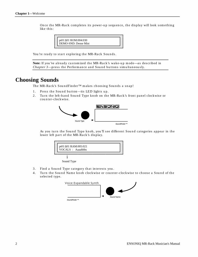
Chapter 1—Welcome
2 ENSONIQ MR-Rack Musician's Manual
Once the MR-Rack completes its power-up sequence, the display will look somethinglike this:
pt01:§01 ROM:004:030DEMO-SND: Dense Mist
You’re ready to start exploring the MR-Rack Sounds.
Note: If you’ve already customized the MR-Rack’s wake-up mode—as described inChapter 3—press the Performance and Sound buttons simultaneously.
C hoosing SoundsThe MR-Rack’s SoundFinder™ makes choosing Sounds a snap!
1. Press the Sound button—its LED lights up.2. Turn the left-hand Sound Type knob on the MR-Rack’s front panel clockwise or
counter-clockwise.
Sound Type
SoundFinder™
As you turn the Sound Type knob, you’ll see different Sound categories appear in thelower left part of the MR-Rack’s display.
pt01:§01 RAM:005:021VOCALS : Aaaahhhs
iSound Type
3. Find a Sound Type category that interests you.4. Turn the Sound Name knob clockwise or counter-clockwise to choose a Sound of the
selected type.
Sound Name
64 Voice Expandable Synth
SoundFinder™

Chapter 1—Welcome
ENSONIQ MR-Rack Musician's Manual 3
Sound names appear on the lower right-hand portion of the display.
pt01:§01 RAM:001:015VOCALS :Airy Voices
iSound Name
5. To hear what a Sound sounds like, press the Audition button. A brief demo of theSound will play. (You can change what plays when you press the Audition button—see“Auditioning Sounds on the MR-Rack” in Chapter 3.)If you’ve already connected your MR-Rack to your MIDI set-up, you can set yourcontroller to MIDI channel 1 and use it to play the Sound. You can also use MIDIprogram changes to select other Sounds. Chapter 2 shows how the MR-Rack can bewired into your rig.
U nde r st anding the M R - R ac kThe MR-Rack is easy to use, once you understand its simple internal structure. Here’s howit works.
SoundsSounds are the basic building blocks of the MR-Rack. They’re constructed from digitalsound waves resident in the MR-Rack’s permanent memory.
If you’ve got a Macintosh or IBM-compatible computer, you can also create your ownSounds using the Unisyn editor ENSONIQ will supply to you when you send in yourcompleted MR-Rack warranty card.
You can add additional Sounds by purchasing MRC Series Sound Cards and ENSONIQ EXPSeries Wave Expansion Boards, which will be explained later in this chapter.
PartsThe MR-Rack can play 16 individual Sounds at once. Each Sound fits into one of 16 slots,called Parts. You can select any MR-Rack Sound for use by any Part.
Each Part can have its own MIDI channel, and provides options—called Part parameters—forcontrolling the behavior of the Part. Part parameters also offer tools that allow each Part toshape the Sound it uses. See Chapter 4 for details.
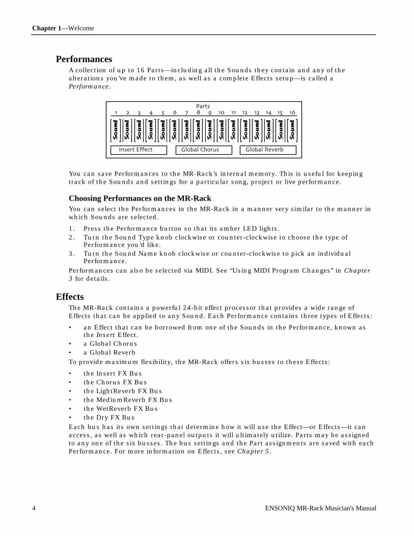
Chapter 1—Welcome
4 ENSONIQ MR-Rack Musician's Manual
PerformancesA collection of up to 16 Parts—including all the Sounds they contain and any of thealterations you’ve made to them, as well as a complete Effects setup—is called aPerformance.
You can save Performances to the MR-Rack’s internal memory. This is useful for keepingtrack of the Sounds and settings for a particular song, project or live performance.
Choosing Performances on the MR-RackYou can select the Performances in the MR-Rack in a manner very similar to the manner inwhich Sounds are selected.
1. Press the Performance button so that its amber LED lights.2. Turn the Sound Type knob clockwise or counter-clockwise to choose the type of
Performance you’d like.3. Turn the Sound Name knob clockwise or counter-clockwise to pick an individual
Performance.
Performances can also be selected via MIDI. See “Using MIDI Program Changes” in Chapter3 for details.
EffectsThe MR-Rack contains a powerful 24-bit effect processor that provides a wide range ofEffects that can be applied to any Sound. Each Performance contains three types of Effects:
• an Effect that can be borrowed from one of the Sounds in the Performance, known asthe Insert Effect.
• a Global Chorus• a Global Reverb
To provide maximum flexibility, the MR-Rack offers six busses to these Effects:
• the Insert FX Bus• the Chorus FX Bus• the LightReverb FX Bus• the MediumReverb FX Bus• the WetReverb FX Bus• the Dry FX Bus
Each bus has its own settings that determine how it will use the Effect—or Effects—it canaccess, as well as which rear-panel outputs it will ultimately utilize. Parts may be assignedto any one of the six busses. The bus settings and the Part assignments are saved with eachPerformance. For more information on Effects, see Chapter 5.
Chapter 1—Welcome
ENSONIQ MR-Rack Musician's Manual 5
Drum KitsThe MR-Rack contains a special category of Sounds called Drum Kit Sounds. Drum KitSounds allow you to have up to 64 non-Drum Kit Sounds assigned to individual keys.Though these are most commonly drum and percussion Sounds, you can use any kind ofSound you’d like in a Drum Kit. Each Drum Kit key has its own Volume, Pan, Tuning andEffect settings. You can use as many Drum Kits in a Performance as there are Parts. Inaddition, every Performance offers an editable Drum Kit, called the PerfEditKit, which youcan customize and save as a Drum Kit Sound that you can use again. Drum Kits aredescribed fully in “Editing Drum Kits” Chapter 4.
StaksThe MR-Rack features an innovative device called a Stak, which is used for grouping Soundstogether on a single MIDI channel. Staks make it easy to create layered Sounds andkeyboard splits. Every Performance provides one Stak, which is created by assigning Partsto the designated Stak MIDI channel.
Staks provide a number of improvements over the traditional method of stacking or splittingSounds assigned to a common MIDI channel. In conventional layers and splits, a programchange sent over the common MIDI channel would set all of the layered or split Sounds tothe same program number, ruining your carefully chosen sound selection—Staks, on theother hand, are program-change proof. The Stak MIDI channel can also be changed with asingle adjustment, sparing you the work of reassigning every layered or split componentindividually, should you need to change the channel you want to use. And since the StakMIDI channel is a global setting, you can easily access Staks in ROM Performances withouthaving to copy the Performance into RAM.
For more information on Staks, see “Using Staks” in Chapter 4.
SoundFinder™SoundFinder™ is an exclusive ENSONIQ feature that makes it simple to find the Soundsand Performances you want. Computer users may be familiar with databases, which allowyou to view information in a manner of your choosing. SoundFinder™ operates in much thesame way. The MR-Rack keeps a list of all the Sounds and Performances available to it atany given time, and shows them to you in logical, musically convenient categories calledSound Types and Performance Types.
Sound Types let you view Sounds by instrument family—Vocals or Bells, for example—or bya number of other useful criteria, including the location in the MR-Rack’s memory wherethey reside. The ALL-SND category is especially useful, since it shows all of the MR-Rack’sSounds arranged in alphabetical order. If you program your own sounds, you can storethem in the USER-SND or *CUSTOM SoundFinder categories.
Performance Types allow you to view Performances according to where in the MR-Rack theyreside.
How the MR-Rack’s Memory WorksSounds and Performances are stored in memory locations called banks. Each bank maystore up to 128 Sounds—depending on how much memory each Sound requires—and 32Performances. The MR-Rack is designed to access up to 128 banks. Banks may reside in theMR-Rack’s internal memory or on PCMCIA data cards and ENSONIQ EXP Series WaveExpansion Boards you can purchase separately.
Banks become most important when using MIDI Program Changes to select Sounds andPerformance. Each Sound or Performance is invoked with a Bank Select message—whichtells the MR-Rack where the Sound or Performance resides—and a Program Change

Chapter 1—Welcome
6 ENSONIQ MR-Rack Musician's Manual
message, which pinpoints the Sound or Performance itself.
Tip: When you’d like to know the necessary Bank Select and Program Change for aSound you’ve currently got selected, press the Sounds button and consult the upperright-hand corner of the MR-Rack’s display: the pair of three-digit numbers tell you,first, the Bank Select and, second, the Program Change required for that Sound. Tolearn a Performance’s Bank Select and Program Change, press the Performancebutton—the Performance display shows Bank Select and Program Changeinformation in the same manner as the Sound display.
ROM and RAMROM (“Read Only Memory’”) and RAM (“Random Access Memory”) are the two areas withinthe MR-Rack’s internal memory where Performances and Sounds are stored in banks.
Performances and Sounds saved into ROM memory are permanent and unalterable—thesePerformances and Sounds are always available. (You can edit them using the MR-Rack’sPart parameters, and then save the edited versions to non-ROM memory locations.)
Performances and Sounds you edit or create are saved into the MR-Rack’s RAM memorybank. RAM can be used over and over again, and, therefore, Performances and Soundsstored in RAM can be edited, re-saved or erased, as you wish.
ROM CardsThe Data Card slot on the MR-Rack’s front panel allows you to add new Sounds andPerformances to the MR-Rack through the purchase of ENSONIQ’s MRC Series SoundCards. These PCMCIA ROM cards are inserted into the Data Card slot on the MR-Rack’sfront panel. The Sounds and Performances on these cards are permanent. (You can use thevarious Part parameters to customize them, and then save the edited versions to the MR-Rack’s RAM memory.)
SRAM CardsThe Data Card slot on the MR-Rack’s front panel also allows you to add additional RAMmemory banks through the purchase of SRAM PCMCIA cards, such as ENSONIQ’s MC-512card. These cards are great for storing your own MR-Rack Sounds and Performances.
EXP Series Wave Expansion BoardsThe MR-Rack can be upgraded to hold more digital sound waves and more Sound andPerformance banks with the installation of ENSONIQ EXP Series Wave Expansion Boards.EXP Boards are mounted inside the MR-Rack’s case—you can easily install them yourself!
For more details, see “Using ENSONIQ EXP Series Wave Expansion Boards” in Chapter 7.
The MR-Rack DisplayThe MR-Rack’s display has been designed to provide you with all the information you’ll needas you use the MR-Rack. The display will change as you perform different tasks, since whatyou’ll need to know at any given time will vary depending on what you’re doing. Eachchapter in the MR-Rack Musician’s Manual contains an introductory section describing howthe display will function in that chapter’s context.
P laying the M R - R ac k D e m oThe MR-Rack can play special demonstration songs to give you an idea of how terrific itsounds.
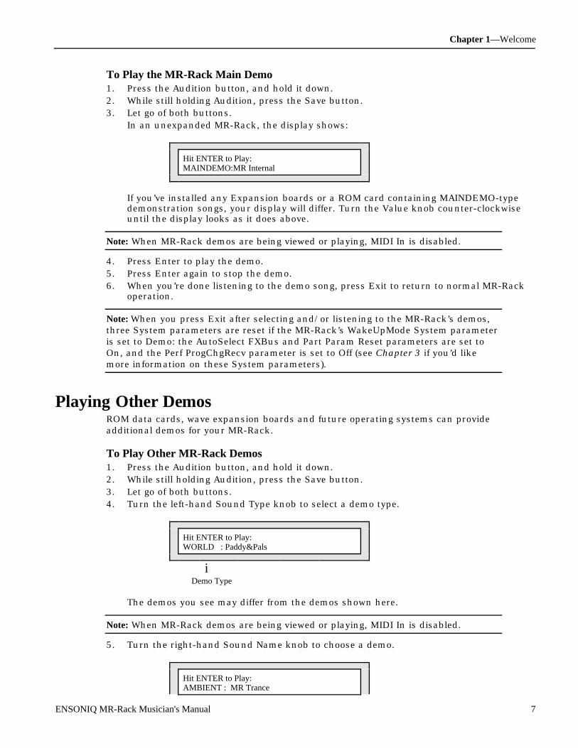
Chapter 1—Welcome
ENSONIQ MR-Rack Musician's Manual 7
To Play the MR-Rack Main Demo1. Press the Audition button, and hold it down.2. While still holding Audition, press the Save button.3. Let go of both buttons.
In an unexpanded MR-Rack, the display shows:
Hit ENTER to Play:MAINDEMO:MR Internal
If you’ve installed any Expansion boards or a ROM card containing MAINDEMO-typedemonstration songs, your display will differ. Turn the Value knob counter-clockwiseuntil the display looks as it does above.
Note: When MR-Rack demos are being viewed or playing, MIDI In is disabled.
4. Press Enter to play the demo.5. Press Enter again to stop the demo.6. When you’re done listening to the demo song, press Exit to return to normal MR-Rack
operation.
Note: When you press Exit after selecting and/or listening to the MR-Rack’s demos,three System parameters are reset if the MR-Rack’s WakeUpMode System parameteris set to Demo: the AutoSelect FXBus and Part Param Reset parameters are set toOn, and the Perf ProgChgRecv parameter is set to Off (see Chapter 3 if you’d likemore information on these System parameters).
P laying Ot he r De m osROM data cards, wave expansion boards and future operating systems can provideadditional demos for your MR-Rack.
To Play Other MR-Rack Demos1. Press the Audition button, and hold it down.2. While still holding Audition, press the Save button.3. Let go of both buttons.4. Turn the left-hand Sound Type knob to select a demo type.
Hit ENTER to Play:WORLD : Paddy&Pals
iDemo Type
The demos you see may differ from the demos shown here.
Note: When MR-Rack demos are being viewed or playing, MIDI In is disabled.
5. Turn the right-hand Sound Name knob to choose a demo.
Hit ENTER to Play:AMBIENT : MR Trance
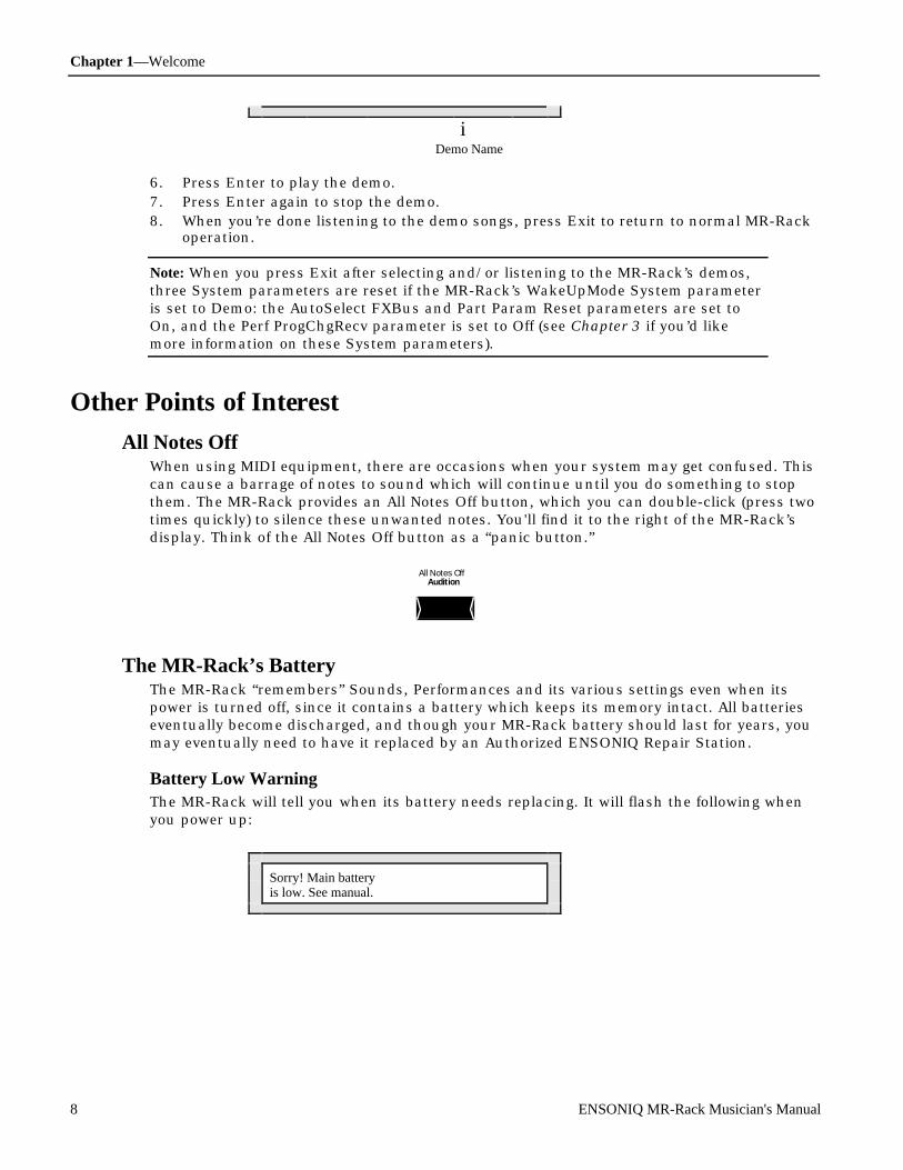
Chapter 1—Welcome
8 ENSONIQ MR-Rack Musician's Manual
i Demo Name
6. Press Enter to play the demo.7. Press Enter again to stop the demo.8. When you’re done listening to the demo songs, press Exit to return to normal MR-Rack
operation.
Note: When you press Exit after selecting and/or listening to the MR-Rack’s demos,three System parameters are reset if the MR-Rack’s WakeUpMode System parameteris set to Demo: the AutoSelect FXBus and Part Param Reset parameters are set toOn, and the Perf ProgChgRecv parameter is set to Off (see Chapter 3 if you’d likemore information on these System parameters).
Ot he r P oint s of In te r e st
All Notes OffWhen using MIDI equipment, there are occasions when your system may get confused. Thiscan cause a barrage of notes to sound which will continue until you do something to stopthem. The MR-Rack provides an All Notes Off button, which you can double-click (press twotimes quickly) to silence these unwanted notes. You'll find it to the right of the MR-Rack’sdisplay. Think of the All Notes Off button as a “panic button.”
All Notes OffAudition
The MR-Rack’s BatteryThe MR-Rack “remembers” Sounds, Performances and its various settings even when itspower is turned off, since it contains a battery which keeps its memory intact. All batterieseventually become discharged, and though your MR-Rack battery should last for years, youmay eventually need to have it replaced by an Authorized ENSONIQ Repair Station.
Battery Low WarningThe MR-Rack will tell you when its battery needs replacing. It will flash the following whenyou power up:
Sorry! Main batteryis low. See manual.

Chapter 1—Welcome
ENSONIQ MR-Rack Musician's Manual 9
This display will appear only briefly, and then allow you to proceed normally. Make sure thateverything in RAM that you’d like to keep—or any special System settings—has been safelystored on a Data Card or external MIDI storage device, and take the MR-Rack to anAuthorized ENSONIQ Repair Station as soon as possible to have the battery replaced.
For more about saving MR-Rack data, see Chapter 6.
If You Experience Odd BehaviorIf your MR-Rack is behaving peculiarly—for instance, the display is showing characters thatshouldn’t be there, or you’re experiencing surprising Unexpected Event messages—a softreset may cure the problem. There are three special procedures you can try:
• A soft reset is similar to turning the MR-Rack’s power off and then on again. Thisprocedure doesn’t erase or adversely affect the contents of the MR-Rack’s memory.
• A reinitialization procedure clears out the MR-Rack’s internal memory, including anysystem data corruption. Reinitializing erases the contents of the MR-Rack’s internalmemory. This means that any Performances, Sounds, Effect set-ups or PerfEditKitsstored in RAM will be lost. If you decide to reinitialize, try saving any items you want topreserve to a Data Card or via MIDI SysEx (see Chapter 6 for details).
• A hard reinitialization procedure performs a very deep-level reinitialization of the MR-Rack. This means that any Performances, Sounds, Effect set-ups or PerfEditKits storedin RAM will be lost. If you decide to reinitialize, try saving any items you want topreserve to a Data Card or via MIDI SysEx (see Chapter 6 for details). This procedureshould be used in cases when the MR-Rack’s front-panel buttons, for some reason,don’t allow you to perform a standard reinitialization.
To Perform A Soft Reset1. Press and hold down the Save button.2. While still holding Save, press the Exit button.
If performing a soft reset doesn’t end the strange occurrences, you may need toreinitialize the MR-Rack. Make sure that everything in RAM that you’d like to keep—orany special System settings—has been safely stored on a Data Card or external MIDIstorage device before you reinitialize, since reinitialization will clear the MR-Rack’sinternal memory.
To Perform a Standard ReinitializationMake sure that everything in RAM that you’d like to keep—or any special Systemsettings—has been safely stored on a Data Card or external MIDI storage device before youreinitialize, since reinitialization will clear the MR-Rack’s internal memory.
1. Press and hold down the Save button.2. While still holding Save, press the Enter button.3. Let go of both buttons.4. Press the Enter button again to perform the reinitialization
To Perform a Hard ReinitializationMake sure that everything in RAM that you’d like to keep—or any special Systemsettings—has been safely stored on a Data Card or external MIDI storage device before youreinitialize, since reinitialization will clear the MR-Rack’s internal memory.
1. Using its front-panel Power switch, turn the MR-Rack’s power off.The hard reinitialization process is performed by switching the MR-Rack off and oneight times in rapid succession. Use the following technique:
2. Turn the MR-Rack’s power back on just until the display flickers on, then shut if offagain, then immediately back on—do this eight times.If reinitializing the MR-Rack fails to correct the problem, contact an AuthorizedENSONIQ Repair Station.

Chapter 1—Welcome
10 ENSONIQ MR-Rack Musician's Manual
A vailable Opt ions f or Your M R - R ac kThese optional accessories are available from your Authorized ENSONIQ Dealer:
• EXP Series Wave Expansion Boards — a user-installable board for Sound memoryexpansion. Each EXP Board contains 256 ROM Sounds, up to 24 MB of wave ROM,with Performances and demos. The MR-Rack can have up to three different EXP WaveExpansion Boards.
• ROM Card — a PCMCIA type ROM card containing 256 ROM Sounds, and 32 ROMPerformances
• SRAM Card, including ENSONIQ’s MC-512 Card — a PCMCIA type SRAM cardcontaining a variable number of banks of Sounds and Performances. The number ofbanks on a card depends on the size of the card. Each bank is equal in size to the baseunit RAM, and can hold the same number of Sounds (up to 128 RAM Sounds per bank)and Performances (128 RAM Performances per bank). The number of RAM Soundsdepends on the number of layers in each Sound.
N e e d M or e He lp?Whether you’re an aspiring programmer looking for additional information about basic effectprocessing techniques and MIDI theory, or a professional sound engineer working withadvanced applications, you may want more detailed information beyond the scope of thismanual. The following books can help enhance your understanding of effect processing,MIDI, and related topics. These, in addition to the numerous monthly magazines, provide awealth of information. While we don’t endorse any one of these publications, we offer thispartial list as a resource for you to draw on.
The Mix BookshelfFor prices and more information call: (800) 233-9604
MIDIBECOMING A COMPUTER MUSICIAN, Jeff BowenMAKING MUSIC WITH YOUR COMPUTER, David (Rudy) Trubitt, Ed.MIDI: A COMPREHENSIVE INTRODUCTION, Joseph RothsteinMIDI XPLAINED, Steinberg/JonesTHE MIDI MANUAL, David HuberUNDERSTANDING MIDI, David WillsWHAT’S MIDI?, Jon Eiche
RECORDINGIMPROVING YOUR SIGNAL PROCESSING SKILLS, (cassette & manual) Bill GibsonMASTER HANDBOOK OF ACOUSTICS, F. Alton EverestMODERN RECORDING TECHNIQUES, Huber & RunsteinSOUND REINFORCEMENT HANDBOOK, Davis & Jones
SYNTHESISFUNDAMENTAL TECHNOLOGIES OF THE SYNTHESIZER, Errol G. SpecterSYNTHESIZER PERFORMANCE, Jeff PressingWHAT’S A SYNTHESIZER?, Jon Eiche
VIDEOSSHAPING YOUR SOUND, (video series) Tom Lubin
Alfred Publishing CompanyFor prices and more information call (818) 891-5999
Chapter 1—Welcome
ENSONIQ MR-Rack Musician's Manual 11
MIDIADVANCED MIDI APPLICATIONS, GPIBASIC MIDI APPLICATIONS, GPIWHAT IS MIDI?, GPI
Hal Leonard PublishingFor prices and more information call (414) 774-3630
MIND OVER MIDI, GPITUNING IN: MICROTONALITY IN ELECTRONIC MUSIC, Scott R. Wilkinson
Monthly MagazinesThe following magazines offer many specific articles and columns that can provideadditional information.
THE TRANSONIQ HACKERFor prices and more information about this independent news magazine for ENSONIQUsers, call (503) 227-6848
KEYBOARDFor subscription rates and more information call (800) 289-9919
ELECTRONIC MUSICIANFor subscription rates and more information call (800) 888-5139
HOME & STUDIO RECORDINGFor subscription rates and more information call (818) 407-0744
MIXFor subscription rates and more information call (800) 888-5139
EQFor subscription rates and more information call (212) 213-3444

Chapter 2—Connections
ENSONIQ MR-Rack Musician's Manual 1
Ch apt e r 2Con ne ct i ons
Int r oduc t ionThe MR-Rack is an outstanding addition to any MIDI set-up. This chapter describes how toconnect the MR-Rack in some of the most popular MIDI environments.
The key to setting up any MIDI system is to approach the process in an orderly, methodicalmanner. As each cable or wire is added, the system grows in complexity. If you have a firmgrasp of what’s connected, and where, you’ll find managing your rig to be much morepleasant. As you add more gear—or troubleshoot—the extra care you take now will pay off inthe ease with which you’ll be able to adapt your system to future needs.
To Get ReadyIt’s always good policy to turn everything off—and all volume settings down—before you wireequipment together. This protects you and your gear from unwelcome surprises.
1. Turn the volume off for each piece of equipment you plan to include in your set-up.2. Turn down any mixer faders or other volume controls for the sound system you’re
using.3. Turn off the power for everything being included in your set-up.
What Connections Need to be Made?In any MIDI system, there are three types of connections to be made:
• MIDI connections• Audio connections• Power connections
M aking MID I C onne c t ionsThe MR-Rack will communicate with the rest of your equipment via MIDI. The nature ofthese connections and the number of MIDI cables you’ll need varies, depending on your set-up. Each system has its own needs, which we’ll explain in the individual set-ups in thischapter.
The MIDI set-ups described in “Making MIDI Connections” are:
• Using the MR-Rack with a controller• Using the MR-Rack with a workstation• Using the MR-Rack with a computer/stand-alone sequencer• Editing Sounds with the MR-Rack and a computer• Sequencing with the MR-Rack, a computer and a controller• Using the MR-Rack with a computer, a controller and a merger• Using the MR-Rack with a computer, a controller and a MIDI patchbay
If you’ve got questions about MIDI itself, or any of the terms above, consult the Glossary or“What Is MIDI?” sections of Chapter 9.
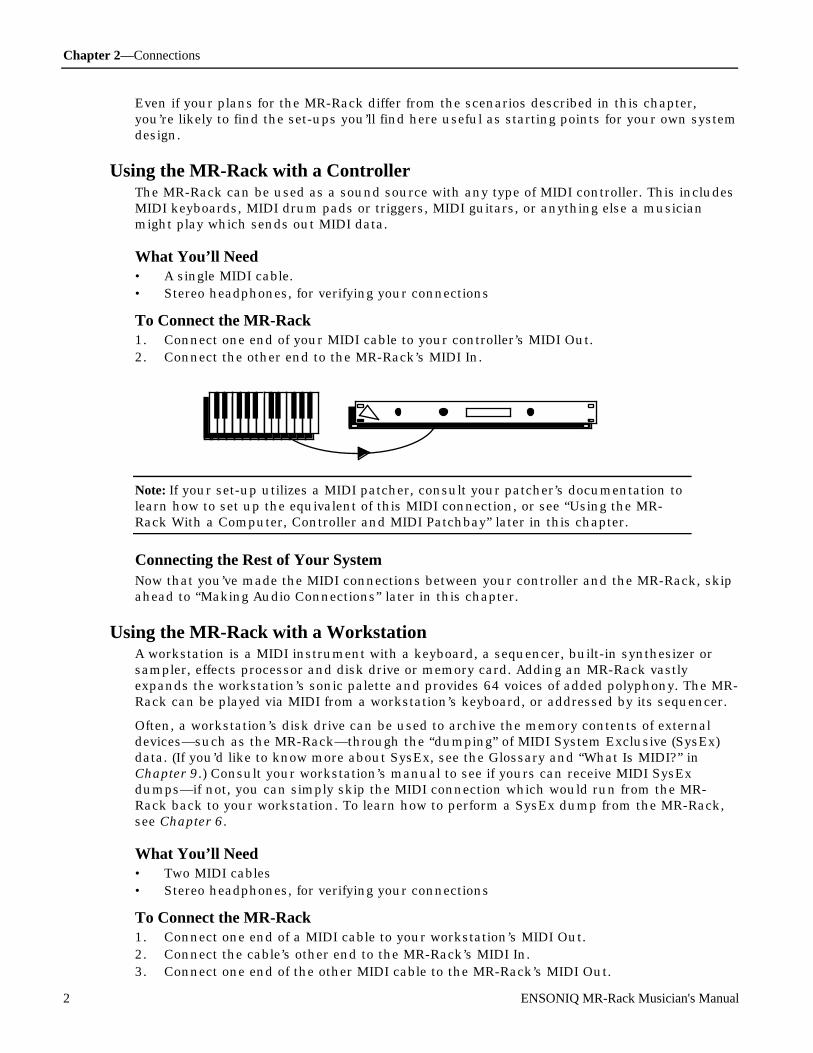
Chapter 2—Connections
2 ENSONIQ MR-Rack Musician's Manual
Even if your plans for the MR-Rack differ from the scenarios described in this chapter,you’re likely to find the set-ups you’ll find here useful as starting points for your own systemdesign.
Using the MR-Rack with a ControllerThe MR-Rack can be used as a sound source with any type of MIDI controller. This includesMIDI keyboards, MIDI drum pads or triggers, MIDI guitars, or anything else a musicianmight play which sends out MIDI data.
What You’ll Need• A single MIDI cable.• Stereo headphones, for verifying your connections
To Connect the MR-Rack1. Connect one end of your MIDI cable to your controller’s MIDI Out.2. Connect the other end to the MR-Rack’s MIDI In.
Note: If your set-up utilizes a MIDI patcher, consult your patcher’s documentation tolearn how to set up the equivalent of this MIDI connection, or see “Using the MR-Rack With a Computer, Controller and MIDI Patchbay” later in this chapter.
Connecting the Rest of Your SystemNow that you’ve made the MIDI connections between your controller and the MR-Rack, skipahead to “Making Audio Connections” later in this chapter.
Using the MR-Rack with a WorkstationA workstation is a MIDI instrument with a keyboard, a sequencer, built-in synthesizer orsampler, effects processor and disk drive or memory card. Adding an MR-Rack vastlyexpands the workstation’s sonic palette and provides 64 voices of added polyphony. The MR-Rack can be played via MIDI from a workstation’s keyboard, or addressed by its sequencer.
Often, a workstation’s disk drive can be used to archive the memory contents of externaldevices—such as the MR-Rack—through the “dumping” of MIDI System Exclusive (SysEx)data. (If you’d like to know more about SysEx, see the Glossary and “What Is MIDI?” inChapter 9.) Consult your workstation’s manual to see if yours can receive MIDI SysExdumps—if not, you can simply skip the MIDI connection which would run from the MR-Rack back to your workstation. To learn how to perform a SysEx dump from the MR-Rack,see Chapter 6.
What You’ll Need• Two MIDI cables• Stereo headphones, for verifying your connections
To Connect the MR-Rack1. Connect one end of a MIDI cable to your workstation’s MIDI Out.2. Connect the cable’s other end to the MR-Rack’s MIDI In.3. Connect one end of the other MIDI cable to the MR-Rack’s MIDI Out.

Chapter 2—Connections
ENSONIQ MR-Rack Musician's Manual 3
4. Connect its other end to the workstation’s MIDI In.
Note: If you use a MIDI patcher, consult your patcher’s documentation to learn howto set up the equivalent of these MIDI connections, or see “Using the MR-Rack With aComputer, Controller and MIDI Patchbay” later in this chapter.
Connecting the Rest of Your SystemNow that you’ve made your MIDI connections between your workstation and the MR-Rack,skip ahead to “Making Audio Connections” later in this chapter.
Using the MR-Rack with a Stand-Alone SequencerSequencers provide a means of playing and/or recording MIDI music (including GeneralMIDI music). There are essentially two physical types of sequencers. There are sequencerprograms which run on a personal computer, and there are stand-alone boxes dedicatedsolely to the job of sequencing. This set-up describes how to use a stand-alone sequencerwith the MR-Rack.
Note: If you’ve got a controller and a MIDI merger, you can follow the instructions in“Using the MR-Rack with a Computer, Controller and MIDI Merger” later in thischapter, by simply replacing any references to “computer” with “sequencer.”
A sequencer is also likely to include a disk drive. Often, the drive can be used to archive thememory contents of external devices—such as the MR-Rack—through the “dumping” ofMIDI System Exclusive (SysEx) data. (If you’d like to know more about SysEx, see theGlossary and “What Is MIDI?” in Chapter 9.) Consult your sequencer’s manual to see ifyours can receive MIDI SysEx dumps—if not, you can simply skip the MIDI connectionwhich would run from the MR-Rack back to your sequencer. Chapter 6 describes how toperform a SysEx dump.
What You’ll Need• Two MIDI cables• Stereo headphones, for verifying your connections

Chapter 2—Connections
4 ENSONIQ MR-Rack Musician's Manual
To Connect the MR-Rack1. Connect one end of a MIDI cable to your sequencer’s MIDI Out.2. Connect the cable’s other end to the MR-Rack’s MIDI In.3. Connect one end of the other MIDI cable to the MR-Rack’s MIDI Out.4. Connect its other end to the sequencer’s MIDI In.
Note: If you use a MIDI patcher, consult your patcher’s documentation to learn howto set up the equivalent of these MIDI connections, or see “Using the MR-Rack With aComputer, Controller and MIDI Patchbay” later in this chapter.
Connecting the Rest of Your SystemNow that you’ve made your MIDI connections between your sequencer and the MR-Rack,skip ahead to “Making Audio Connections” later in this chapter.
If you’re using a General MIDI (GM) sequencer, you’ll want to see “Using the MR-Rack forGeneral MIDI Music” near the end of this chapter once you’ve finished setting up.
Editing Sounds with the MR-Rack and a ComputerComputers are powerful musical tools when outfitted with the proper musical hardware andsoftware. Some computers sport MIDI In/Out/Thru jacks. If yours doesn’t, you’ll need topurchase a MIDI interface for your computer.
ENSONIQ will provide you with Unisyn sound editing software for your computer when youfill out and mail in your completed warranty card. Once you’ve installed the Unisyn editoron your computer, you’ll be able to create your own new Sounds for the MR-Rack (Chapter 9provides information on using the Unisyn software).
What You’ll Need• Two MIDI cables• Stereo headphones, for verifying your connections
To Connect the MR-Rack1. Connect one end of a MIDI cable to your computer’s MIDI Out.2. Connect the cable’s other end to the MR-Rack’s MIDI In.3. Connect one end of the other MIDI cable to the MR-Rack’s MIDI Out.

Chapter 2—Connections
ENSONIQ MR-Rack Musician's Manual 5
4. Connect its other end to the computer’s MIDI In.
Note: This set-up is for MR-Rack users working with minimal MIDI hardware. If youown a MIDI merger or a MIDI patchbay, see “Using the MR-Rack with a Computer,Controller and MIDI Merger,” or “Using the MR-Rack with a Computer, Controllerand MIDI Patchbay” later in this chapter.
Connecting the Rest of Your SystemNow that you’ve made your MIDI connections between your computer and the MR-Rack,skip ahead to “Making Audio Connections” later in this chapter.
Sequencing with the MR-Rack, a Computer and a ControllerComputers are powerful musical tools when outfitted with the proper musical hardware andsoftware. Some computers sport MIDI In/Out/Thru jacks. If yours doesn’t, you’ll need topurchase a MIDI interface for your computer. There are many excellent MIDI sequencingprograms on the market, including General MIDI sequencers. Once you’ve installed one onyour computer, you’ll be able to purchase and play pre-recorded sequences—or record yourown music—using the Sounds onboard the MR-Rack.
This set-up will allow you to play the MR-Rack’s Sounds from your controller whilerecording into the computer sequencer. When the sequencer plays back the music, it willuse the same MR-Rack Sounds. When using a computer sequencer, it’s critical that yourcontroller, sequencer, computer and—if you’re using one—your MIDI interface be configuredcorrectly. Consult their documentation to learn how to use them with a multi-timbralmodule such as the MR-Rack.
What You’ll Need• Two MIDI cables• Stereo headphones, for verifying your connections
To Connect the MR-Rack1. Connect one end of a MIDI cable to your controller’s MIDI Out.2. Connect the cable’s other end to the computer’s MIDI In.3. Connect one end of the other MIDI cable to the computer’s MIDI Out.4. Connect its other end to the MR-Rack’s MIDI In.
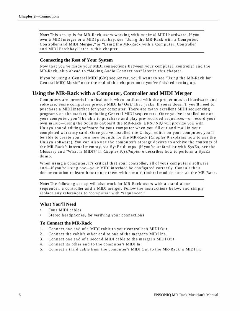
Chapter 2—Connections
6 ENSONIQ MR-Rack Musician's Manual
Note: This set-up is for MR-Rack users working with minimal MIDI hardware. If youown a MIDI merger or a MIDI patchbay, see “Using the MR-Rack with a Computer,Controller and MIDI Merger,” or “Using the MR-Rack with a Computer, Controllerand MIDI Patchbay” later in this chapter.
Connecting the Rest of Your SystemNow that you’ve made your MIDI connections between your computer, controller and theMR-Rack, skip ahead to “Making Audio Connections” later in this chapter.
If you’re using a General MIDI (GM) sequencer, you’ll want to see “Using the MR-Rack forGeneral MIDI Music” near the end of this chapter once you’ve finished setting up.
Using the MR-Rack with a Computer, Controller and MIDI MergerComputers are powerful musical tools when outfitted with the proper musical hardware andsoftware. Some computers provide MIDI In/Out/Thru jacks. If yours doesn’t, you’ll need topurchase a MIDI interface for your computer. There are many excellent MIDI sequencingprograms on the market, including General MIDI sequencers. Once you’ve installed one onyour computer, you’ll be able to purchase and play pre-recorded sequences—or record yourown music—using the Sounds onboard the MR-Rack. ENSONIQ will provide you withUnisyn sound editing software for your computer when you fill out and mail in yourcompleted warranty card. Once you’ve installed the Unisyn editor on your computer, you’llbe able to create your own new Sounds for the MR-Rack (Chapter 9 explains how to use theUnisyn software). You can also use the computer’s storage devices to archive the contents ofthe MR-Rack’s internal memory, via SysEx dumps. (If you’re unfamiliar with SysEx, see theGlossary and “What Is MIDI?” in Chapter 9.) Chapter 6 describes how to perform a SysExdump.
When using a computer, it’s critical that your controller, all of your computer’s softwareand—if you’re using one—your MIDI interface be configured correctly. Consult theirdocumentation to learn how to use them with a multi-timbral module such as the MR-Rack.
Note: The following set-up will also work for MR-Rack users with a stand-alonesequencer, a controller and a MIDI merger. Follow the instructions below, and simplyreplace any references to “computer” with “sequencer.”
What You’ll Need• Four MIDI cables• Stereo headphones, for verifying your connections
To Connect the MR-Rack1. Connect one end of a MIDI cable to your controller’s MIDI Out.2. Connect the cable’s other end to one of the merger’s MIDI Ins.3. Connect one end of a second MIDI cable to the merger’s MIDI Out.4. Connect its other end to the computer’s MIDI In.5. Connect a third cable from the computer’s MIDI Out to the MR-Rack’ s MIDI In.
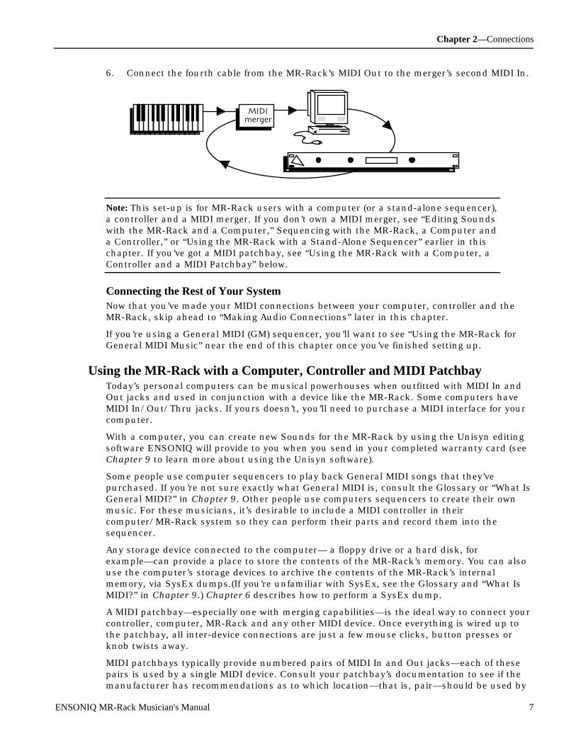
Chapter 2—Connections
ENSONIQ MR-Rack Musician's Manual 7
6. Connect the fourth cable from the MR-Rack’s MIDI Out to the merger’s second MIDI In.
MIDImerger
Note: This set-up is for MR-Rack users with a computer (or a stand-alone sequencer),a controller and a MIDI merger. If you don’t own a MIDI merger, see “Editing Soundswith the MR-Rack and a Computer,” Sequencing with the MR-Rack, a Computer anda Controller,” or “Using the MR-Rack with a Stand-Alone Sequencer” earlier in thischapter. If you’ve got a MIDI patchbay, see “Using the MR-Rack with a Computer, aController and a MIDI Patchbay” below.
Connecting the Rest of Your SystemNow that you’ve made your MIDI connections between your computer, controller and theMR-Rack, skip ahead to “Making Audio Connections” later in this chapter.
If you’re using a General MIDI (GM) sequencer, you’ll want to see “Using the MR-Rack forGeneral MIDI Music” near the end of this chapter once you’ve finished setting up.
Using the MR-Rack with a Computer, Controller and MIDI PatchbayToday’s personal computers can be musical powerhouses when outfitted with MIDI In andOut jacks and used in conjunction with a device like the MR-Rack. Some computers haveMIDI In/Out/Thru jacks. If yours doesn’t, you’ll need to purchase a MIDI interface for yourcomputer.
With a computer, you can create new Sounds for the MR-Rack by using the Unisyn editingsoftware ENSONIQ will provide to you when you send in your completed warranty card (seeChapter 9 to learn more about using the Unisyn software).
Some people use computer sequencers to play back General MIDI songs that they’vepurchased. If you’re not sure exactly what General MIDI is, consult the Glossary or “What IsGeneral MIDI?” in Chapter 9. Other people use computers sequencers to create their ownmusic. For these musicians, it’s desirable to include a MIDI controller in theircomputer/MR-Rack system so they can perform their parts and record them into thesequencer.
Any storage device connected to the computer— a floppy drive or a hard disk, forexample—can provide a place to store the contents of the MR-Rack’s memory. You can alsouse the computer’s storage devices to archive the contents of the MR-Rack’s internalmemory, via SysEx dumps.(If you’re unfamiliar with SysEx, see the Glossary and “What IsMIDI?” in Chapter 9.) Chapter 6 describes how to perform a SysEx dump.
A MIDI patchbay—especially one with merging capabilities—is the ideal way to connect yourcontroller, computer, MR-Rack and any other MIDI device. Once everything is wired up tothe patchbay, all inter-device connections are just a few mouse clicks, button presses orknob twists away.
MIDI patchbays typically provide numbered pairs of MIDI In and Out jacks—each of thesepairs is used by a single MIDI device. Consult your patchbay’s documentation to see if themanufacturer has recommendations as to which location—that is, pair—should be used by
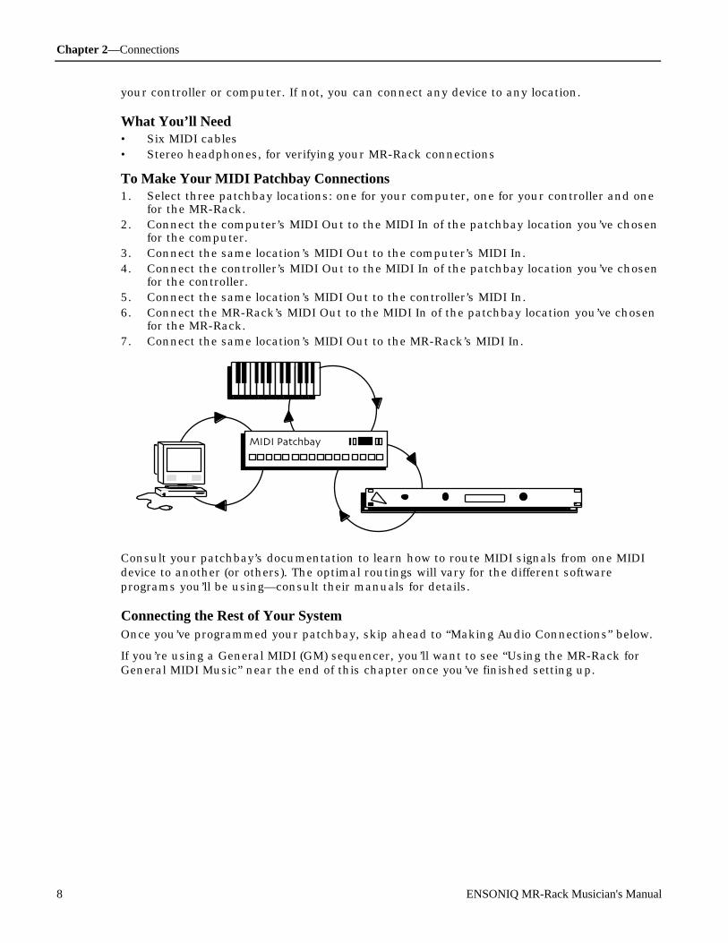
Chapter 2—Connections
8 ENSONIQ MR-Rack Musician's Manual
your controller or computer. If not, you can connect any device to any location.
What You’ll Need• Six MIDI cables• Stereo headphones, for verifying your MR-Rack connections
To Make Your MIDI Patchbay Connections1. Select three patchbay locations: one for your computer, one for your controller and one
for the MR-Rack.2. Connect the computer’s MIDI Out to the MIDI In of the patchbay location you’ve chosen
for the computer.3. Connect the same location’s MIDI Out to the computer’s MIDI In.4. Connect the controller’s MIDI Out to the MIDI In of the patchbay location you’ve chosen
for the controller.5. Connect the same location’s MIDI Out to the controller’s MIDI In.6. Connect the MR-Rack’s MIDI Out to the MIDI In of the patchbay location you’ve chosen
for the MR-Rack.7. Connect the same location’s MIDI Out to the MR-Rack’s MIDI In.
MIDI Patchbay
Consult your patchbay’s documentation to learn how to route MIDI signals from one MIDIdevice to another (or others). The optimal routings will vary for the different softwareprograms you’ll be using—consult their manuals for details.
Connecting the Rest of Your SystemOnce you’ve programmed your patchbay, skip ahead to “Making Audio Connections” below.
If you’re using a General MIDI (GM) sequencer, you’ll want to see “Using the MR-Rack forGeneral MIDI Music” near the end of this chapter once you’ve finished setting up.

Chapter 2—Connections
ENSONIQ MR-Rack Musician's Manual 9
M aking Audio C onne c t ionsIn any set-up, you’ll need to determine what type of audio connection you’d prefer toestablish between the MR-Rack and the rest of your system. There are a number of options.
• You can listen to the MR-Rack with headphones plugged into the front-panel Phonesjack. This is great for privacy—when you’re practicing, no one else can hear what you’reup to. It’s also a convenient way to troubleshoot your system, and it’s perfect for simplyexperiencing the MR-Rack’s crystal-clear sound without added noise from otherequipment in your rig. The MR-Rack’s Volume knob controls your listening volume.
Phones Volume
Using headphones is always available as an option, regardless of other audioconnections you’ve made with the MR-Rack.Plugging them in does not automatically mute the other audio outputs from the MR-Rack.
• If you’d prefer to use the MR-Rack in mono through a traditional keyboard or guitaramplifier, or through a single fader on a mixing console, connect one end of a 1/4”phone-type audio cable to the Main Out Left jack on the MR-Rack’s back panel, and theother end to your amplifier or mixer. The “MR-Rack Output Jacks” section in Chapter 9contains technical information about the MR-Rack’s output jacks.
Aux OutRight Left
Mono
Right Left
Mono
• If you’d like to operate your MR-Rack in stereo through a pair of faders on a mixingconsole, a stereo amplifier or two separate mono amps, you’ll need two 1/4” phone-typecables. Connect one end of each cable to the MR-Rack’s rear-panel Main Out Left andRight jacks and the other end to your desired destination. The “MR-Rack Output Jacks”section in Chapter 9 contains technical information about the MR-Rack’s output jacks.
Aux OutRight Left
Mono
Right Left
Mono
• You can also connect the MR-Rack to your home stereo, though a bit of caution isrequired. The MR-Rack is capable of producing a far greater dynamic range than ahome stereo typically encounters when playing compact discs, cassettes and LPs. See“Setting Volume Levels” later in this chapter to learn how to safely set the MR-Rack’sVolume when using it with a home stereo. You’ll need two 1/4”-phone-to-RCA-type

Chapter 2—Connections
10 ENSONIQ MR-Rack Musician's Manual
cables, or you’ll need to create some by attaching adapters to standard 1/4” phone orRCA cables. Connect the 1/4” phone plug end of each 1/4”-to-RCA cable to the MR-Rack’s rear-panel Main Out Left and Right jacks and the RCA end to your stereo’sauxiliary inputs. The “MR-Rack Output Jacks” section in Chapter 9 contains technicalinformation about the MR-Rack’s output jacks.
Aux OutRight Left
Mono
Right Left
Mono
• If you’re connecting the MR-Rack to an audio patch bay, or if you’ve got four availableinputs on your mixing console, you may elect to use all of the MR-Rack’s Outs. The MR-Rack offers—in addition to its Main Outs—a pair of Aux Outs, useful for extractingSounds or groups of Sounds from the MR-Rack’s Main Outs mix. This allows you totreat the extracted material with its own outboard processing, or to control its volumemore easily by assigning it its own faders on a mixer. To use all four Outs, you’ll needfour 1/4” phone-type cables. connect one end of each to the MR-Racks’ rear-panel Mainand Aux Outs Left and Right, and the other end to a patch bay position or mixerchannel. The “MR-Rack Output Jacks” section in Chapter 9 contains technicalinformation about the MR-Rack’s output jacks.
Aux OutRight Left
Mono
Right Left
Mono
Chapter 3 of the MR-Rack Musician’s Manual describes how to route specific Sounds to theAux Outs. The MR-Rack also provides a simple switch for easily sending everything you mayhave routed to the Aux Outs back into the Main Outs mix. See “Using the MR-Rack’s FourOutputs” in Chapter 3.
M aking the P ow e r C onne c t ionThe MR-Rack requires grounded AC power, supplied through the power cord that came withyour MR-Rack. The MR-Rack power supply is intelligent and will adjust to your localvoltage.
To Connect the MR-Rack’s AC Power1. Connect one end of the MR-Rack’s power cable to a grounded AC outlet.2. Connect the other end of the MR-Rack’s power cord to the jack labeled “Line” on the
MR-Rack’s rear panel.3. Connect the other pieces of equipment in your system requiring AC power to AC outlets.
Powering UpYou should always turn on the device which will be transmitting MIDI before you turn onthe device which will be receiving it. If you have a series of MIDI devices, start with the firstdevice in the chain, then power up the second, the third, and so on. This prevents

Chapter 2—Connections
ENSONIQ MR-Rack Musician's Manual 11
unpleasant surprises which can result from unplanned MIDI information being “spit” out oftransmitting devices as they power up. Such MIDI garbage could confuse a receiving device,and possibly disable it temporarily. If this should happen for some reason, turn the MR-Rack’s power off, and then back on.
C onf ir m ing You r MID I C on ne ct ion It’s important when setting up a MIDI system to verify your connections in an orderlymanner, one step at a time. This is the best way to ascertain what’s working and what isn’t.
The following verification procedure details how to confirm that the MR-Rack is receivingMIDI properly. If your set-up requires communication in the opposite direction—from theMR-Rack back to another device—you’ll need to consult that device’s documentation toascertain its method for verifying MIDI reception.
MIDI patchbay users should test their set-up with either the controller or the computersending MIDI to the MR-Rack.
To Verify that the MR-Rack is Receiving MIDI• Play a few notes on your controller or play a sequence from your computer or stand-
alone sequencer.• If you’re using the “Editing Sounds with the MR-Rack and a Computer” set-up, and
Unisyn editing software, open up a Sound-editing window and use the Screen Keys orMouse Play feature to play a few notes. (Consult your Unisyn manual for information onconfiguration instructions and using these features.)
There’s a MIDI light on the MR-Rack’s front panel, located between the Audition and Savebuttons.
All Notes OffAudition
MIDI Save
As you play, you should see it flicker. This tells you that your MIDI controller is properlyconnected to your MR-Rack.
If the MR-Rack’s MIDI light doesn’t flicker as you play your controller:
1. Check your controller’s MIDI transmission settings to make sure that it is set totransmit MIDI. Consult your controller’s manual if you’re not sure how to do this.
2. Double-check your MIDI cables. Is your controller’s MIDI Out connected to the MR-Rack’s MIDI In?
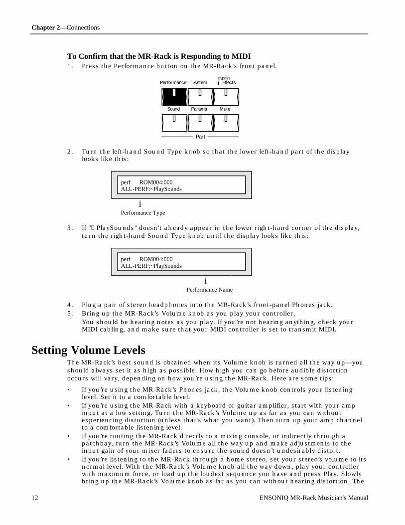
Chapter 2—Connections
12 ENSONIQ MR-Rack Musician's Manual
To Confirm that the MR-Rack is Responding to MIDI1. Press the Performance button on the MR-Rack’s front panel.
Performance System Effects
Sound Params Mute
Part
Bypass
2. Turn the left-hand Sound Type knob so that the lower left-hand part of the displaylooks like this:
perf ROM004:000ALL-PERF:~PlaySounds
iPerformance Type
3. If "→PlaySounds" doesn't already appear in the lower right-hand corner of the display,turn the right-hand Sound Type knob until the display looks like this:
perf ROM004:000ALL-PERF:~PlaySounds
iPerformance Name
4. Plug a pair of stereo headphones into the MR-Rack’s front-panel Phones jack.5. Bring up the MR-Rack’s Volume knob as you play your controller.
You should be hearing notes as you play. If you’re not hearing anything, check yourMIDI cabling, and make sure that your MIDI controller is set to transmit MIDI.
Se t t ing Vol um e Le ve lsThe MR-Rack’s best sound is obtained when its Volume knob is turned all the way up—youshould always set it as high as possible. How high you can go before audible distortionoccurs will vary, depending on how you’re using the MR-Rack. Here are some tips:
• If you’re using the MR-Rack’s Phones jack, the Volume knob controls your listeninglevel. Set it to a comfortable level.
• If you’re using the MR-Rack with a keyboard or guitar amplifier, start with your ampinput at a low setting. Turn the MR-Rack’s Volume up as far as you can withoutexperiencing distortion (unless that’s what you want). Then turn up your amp channelto a comfortable listening level.
• If you’re routing the MR-Rack directly to a mixing console, or indirectly through apatchbay, turn the MR-Rack’s Volume all the way up and make adjustments to theinput gain of your mixer faders to ensure the sound doesn’t undesirably distort.
• If you’re listening to the MR-Rack through a home stereo, set your stereo’s volume to itsnormal level. With the MR-Rack’s Volume knob all the way down, play your controllerwith maximum force, or load up the loudest sequence you have and press Play. Slowlybring up the MR-Rack’s Volume knob as far as you can without hearing distortion. The

Chapter 2—Connections
ENSONIQ MR-Rack Musician's Manual 13
MR-Rack is capable of producing a far greater dynamic range than a home stereotypically encounters when playing compact discs, cassettes and LPs, and you’ll have tomake sure that loud notes from the MR-Rack will not damage your system.
U sing the M R - R ac k f or Ge ne r al M ID I Music Once you’ve made all of your connections, getting the MR-Rack ready for General MIDI issimple:
• Press the System button until the display shows:
System parameters:Hit ENTER for GM!
• Press the Enter button.
Enter
Select Part
Exit
16
1
The MR-Rack is now General-MIDI-ready. Start your General MIDI sequencer and the MR-Rack will do the rest.
M oving OnSince the MR-Rack is capable of playing 16 different Sounds at once—on 16 different MIDIchannels—you’ll want to get familiar with the way MIDI channels, Sounds and Parts worktogether. For a brief overview of the MR-Rack, see “Understanding the MR-Rack” in the firstchapter of the MR-Rack Musician’s Manual, Welcome. For more detailed information on thissubject, turn to Chapter 4.

Chapter 3—Personalizing Your System
To access the Parameters described on this page (unless otherwise noted):Press the System button, turn the Parameter knob to locate the parameter,
and then turn the Value knob to change the parameter's setting.
ENSONIQ MR-Rack Musician’s Manual 1
Ch apt e r 3P er son ali z in g Your Sys t em
The MR-Rack offers a range of options that allow you tailor its behavior to suit your way ofworking. These global, system-wide settings operate in the background, letting you get onwith the art of making music. They remain in effect at all times and are preserved when theMR-Rack’s power is switched off.
To access these options, press the System button. When you press the System button, itsyellow LED will light.
Performance System Effects
Sound Params Mute
Part
Bypass
Each of the System options is called a parameter. When you change the setting of aparameter, you are editing the parameter’s value.
To select System parameters, turn the Parameter knob. To edit a System parameter’s value,turn the Value knob.
Parameter Value
When selecting and editing System parameters, the MR-Rack always shows “Systemparameters:” on the top line of the display.
U sing the Global Pit c h Be nd Se t t ingsA Pitch Bend Wheel is a spring-loaded wheel typically located to the far left of a MIDIkeyboard. It’s most commonly used to bend the pitch of notes up or down by pushing thewheel forward (up) or pulling it back (down). Some manufacturers employ a left/rightscheme.
Most MR-Rack Sounds are programmed to respond to MIDI Pitch Bend messages in waysappropriate to the Sound. The MR-Rack also offers a global Pitch Bend set-up, which isalways available. By setting the Part’s Pitch Bend Up and Down Part parameters to “Sys,”

Chapter 3—Personalizing Your System
To access the Parameters described on this page (unless otherwise noted):Press the System button, turn the Parameter knob to locate the parameter,
and then turn the Value knob to change the parameter's setting.
2 ENSONIQ MR-Rack Musician’s Manual
you can instruct a Part—and its Sound—to use the global Pitch Bend settings instead ofthose originally programmed into the Sound. (See “Controlling a Part’s Pitch Bend Response”in Chapter 4 for details.)
The MR-Rack offers three parameters for controlling the global Pitch Bend range:
• Pitch Bend Up• Pitch Bend Down• PitchBendMode
Global Pitch Bend Up and DownBoth Pitch Bend Up and Pitch Bend Down have their own individual settings, and either canbe set to raise or lower the pitch of any Part Sound whose Pitch Bend Up or Down Partparameter is set to “Sys.”
To Determine the Global Pitch Bend Up Range1. Press System.2. Turn the Parameter knob until the display shows “Pitch Bend Up=.”
The global Pitch Bend Up parameter can be set to:• 1-12dn or 1-12up—the pitch of Part Sounds whose Pitch Bend Up=Sys will be
lowered or raised by the number of equal-temper semitones set here when a PitchBend Wheel is pushed all the way forward
• Off—any Part Sounds whose Pitch Bend Up=Sys will ignore MIDI messagesreceived from a Pitch Bend Wheel pushed forward
3. Use the Value knob to set the Pitch Bend Up value you desire.
To Determine the Global Pitch Bend Down Range1. Press System.2. Turn the Parameter knob until the display shows “Pitch Bend Down=.”
The global Pitch Bend Down parameter can be set to:• 1-12dn or 1-12up—the pitch of Part Sounds whose Pitch Bend Down=Sys will be
lowered or raised by the number of equal-temper semitones set here when a PitchBend Wheel is pulled all the way back
• Off—any Part Sounds whose Pitch Bend Up=Sys will ignore MIDI messagesreceived from a Pitch Bend Wheel pulled back
3. Use the Value knob to set the Pitch Bend Down value you desire.
Setting the Global Pitch Bend ModeThe PitchBendMode parameter unlocks a powerful feature that allows you to decide whichnotes will be affected by Pitch Bend messages when Part Sounds use the global Pitch Bend.(See “Controlling a Part’s Pitch Bend Response” in Chapter 4 for details.) It can be set to oneof three values:
• Normal—Pitch Bend messages will affect all notes currently sounding.• Held—Pitch Bend messages will affect only those notes sounding from keys which are
being physically held down.Notes held with the sustain pedal or in their release stage will remain at their originalpitch. This feature can be used to create guitar-style pitch bends or to “paint” withpitch, leaving different notes sustaining at different pitches.
• Prog—the global Pitch Bend will not alter the Normal/Held settings programmed into
Chapter 3—Personalizing Your System
To access the Parameters described on this page (unless otherwise noted):Press the System button, turn the Parameter knob to locate the parameter,
and then turn the Value knob to change the parameter's setting.
ENSONIQ MR-Rack Musician’s Manual 3
any Sounds using the global Pitch Bend set-up.
To Determine the Global Pitch Bend’s Behavior1. Press System.2. Turn the Parameter knob until the display shows “PitchBendMode=.”
The global PitchBend Mode parameter can be set to:• Normal—all notes of Part Sounds utilizing the global Pitch Bend will be affected
when Pitch Bend messages are received• Held—only notes of Part Sounds utilizing the global Pitch Bend set-up which are
being physically held down will be affected when Pitch Bend messages are received• Prog—notes set to bend according to the programming of Part Sounds utilizing the
global Pitch Bend will be affected when Pitch Bend messages are received3. Use the Value knob to set the PitchBend Mode to the desired value.
R e t uning the M R - R ac k
Fine Tuning the MR-RackThere may be a time when you need to use the MR-Rack with an instrument that just can’tbe tuned, or if you have to deal with musicians who don’t want to retune for one reason oranother. The tuning parameter allows you to adjust the MR-Rack's tuning to match otherinstruments. The MR-Rack defaults to A=440, with an equi-tempered pitch table.
To Fine Tune the MR-Rack1. Press System.2. Turn the Parameter knob until the display shows “Fine Tuning=.”3. Use the Value knob to set the amount that you want to raise or lower the pitch. The
pitch can be lowered or raised from -50 to +49 cents.
Note: Setting the MR-Rack to 0 cents is equivalent to A=440. 100 cents is theequivalent of a semitone.
Using Pitch TablesThe intervals (or relationships) between notes in a scale can be altered to create special pitchtables. The MR-Rack’s pitch tables have a tuning resolution of 256 cents per semitone. Thedefault pitch table is “EqualTemper,” the western 12-tone equi-tempered pitch table.However, you can select from a large assortment of traditional, modern, ethnic, and exoticpitch tables in the MR-Rack. The MR-Rack also provides a RAM location for a custom pitchtable, and supports the MIDI pitch table Bulk Tuning Dump and Single Note Tuning Changestandards. If you’ve got the appropriate computer program, you can create your own pitchtables, and transmit them to the MR-Rack via SysEx (see “Pitch Tables and the MIDIStandard Tuning Format” in Chapter 9 to learn more).

Chapter 3—Personalizing Your System
To access the Parameters described on this page (unless otherwise noted):Press the System button, turn the Parameter knob to locate the parameter,
and then turn the Value knob to change the parameter's setting.
4 ENSONIQ MR-Rack Musician’s Manual
To Assign a Global Pitch Table1. Press System.2. Turn the Parameter knob until the display shows “PitchTbl=.”3. Use the Value knob to select the pitch table that you want to use. This selects the
system pitch table, and will affect all Parts that have their PitchTbl Part parameter set toPitchTbl=Sys. (See Chapter 4 for details.)
To Assign a Part to a Special Pitch Table1. Use the Select Part Buttons to choose the Part whose pitch table you’d like to set.2. Press the Params button.3. Turn the Parameter knob until the display shows “PitchTbl=.”
PitchTbl can be set to:• Prog—to use the PitchTbl value programmed into the Sound.• Sys—to use the global System PitchTbl.• use one of the special pitch tables built in to the MR-Rack’s memory.
4. Turn the Value knob to set PitchTbl to Sys.
Note: When you select a new Sound for the Part, PitchTbl will be reset to Prog if theSystem Part Param Reset parameter is set to On. The Part Param Reset parameter isdescribed later in this chapter in “Protecting Part Settings.”
This parameter also responds to an NRPN LSB value of 021. See “Using RPNs and NRPNs toEdit Part Parameters” at the end of Chapter 4.
For a complete list of pitch tables and their descriptions, see Chapter 9.
Sync hr oniz ing the M R - R ac k t o MID IMR-Rack Sounds and Insert Effect LFOs and DDLs use Low Frequency Oscillators (LFOs) asa means of creating vibrato and other rhythmic sonic changes. LFOs can be synchronized toa reference tempo. The MR-Rack contains an internal clock to provide such a reference. Theclock can also be synchronized to MIDI clocks received from an external source—this isuseful if you want to use another device (such as a computer sequencer or drum machine)as the master clock source, and want to synchronize the MR-Rack’s LFOs to it.
To Set the Global Tempo Clock as the Timing Reference1. Press System.2. Turn the Parameter knob until the display shows “Tempo Clock Src=.”
The Tempo Clock Src parameter can be set to:• Int—to use the MR-Rack’s own internal clock as the timing source.• MIDI—to use external MIDI clocks as the timing source.
3. Turn the Value knob to set Tempo Clock Src to Int.
To Sync the MR-Rack’s Clock to an External MIDI Device1. Press System.2. Turn the Parameter knob until the display shows “Tempo Clock Src=.”
The Tempo Clock Src parameter can be set to:• Int—to use the MR-Rack's own internal clock as the timing source.
Chapter 3—Personalizing Your System
To access the Parameters described on this page (unless otherwise noted):Press the System button, turn the Parameter knob to locate the parameter,
and then turn the Value knob to change the parameter's setting.
ENSONIQ MR-Rack Musician’s Manual 5
• MIDI—to use external MIDI clocks as the timing source.3. Turn the Value knob to set Tempo Clock Src to MIDI.
To Set the Global Clock TempoIf the Global Tempo Clock Source parameter is set to Int, this parameter sets the tempo ofthe MR-Rack’s internal clock.
1. Press System.2. Turn the Parameter knob until the display shows “System Tempo=.”3. The System Tempo parameter can be set to any tempo from 25 bpm (beats per minute)
to 250 bpm.4. Turn the Value knob to set System Tempo to the tempo that you want to use.
Note: If the Global Tempo Clock Source is set to MIDI, this display will show“MIDIbpm” as its value, and cannot be changed.
P r ot e c t ing P ar t Se t t ingsSounds are programmed with their own optimal Part settings built-in, and when you choosea Sound, those settings are applied to the currently selected Part. The following Partparameters may be reset when you select a new Sound on a Part: FX Bus (see Chapter 5 fordetails), Pitch Bend Up, Pitch Bend Down, Octave Tuning, Coarse Tuning, Fine Tuning,PtchTbl, Glide Mode, Glide Time, Delay Time, SyncLFO&Noise, Normal LFO Rates, LFODepth, LFO Delay Time, Amp Env Attack, Amp Env Decay, Amp Env Release, Filter Cutoff,Filt Env Attack, Filt Env Decay, Filt Env Release and Amp&FiltEnv Vel.
You might prefer to choose new Sounds without losing your current Part settings. You canuse the Part Param Reset System parameter to determine whether or not these Partparameter settings will be retained when you select a new Sound. This parameter affectsSound selection from the MR-Rack’s front panel, as well as Sound selection through thereception of MIDI Program Changes.
The Part Param Reset System parameter also affects the response of Parts to a Reset AllControllers MIDI message. When the ResetControlRecv System parameter—described laterin this chapter—is set to On, a number of Part parameters are reset to default values whenthe MR-Rack receives a Reset All Controllers message. (See “Receiving Reset All ControllersMIDI Messages” later in this chapter.) Setting the Part Param Reset to Off will protect thesettings of the Part parameters listed above from Reset All Controllers MIDI messages.
To Protect Part Parameter Settings When New Sounds are Selected1. Press System.2. Turn the Parameter knob until the display shows “Part Param Reset=.”
The Part Param Reset parameter may be set to:• On—Part parameters will be reset when new Sounds are selected for a Part or
Reset All Controllers MIDI messages are received• Off—Part parameters will not be reset when new Sounds are selected for a Part, or
when Reset All Controllers MIDI messages are received3. Use the Value knob to set Part Param Reset to Off.
To Protect Part Parameters from Reset All Controllers MIDI Messages

Chapter 3—Personalizing Your System
To access the Parameters described on this page (unless otherwise noted):Press the System button, turn the Parameter knob to locate the parameter,
and then turn the Value knob to change the parameter's setting.
6 ENSONIQ MR-Rack Musician’s Manual
1. Press System.2. Turn the Parameter knob until the display shows “Part Param Reset=.”
The Part Param Reset parameter may be set to:• On—Part parameters will be reset when new Sounds are selected for a Part or
Reset All Controllers MIDI messages are received• Off—Part parameters will not be reset when new Sounds are selected for a Part, or
when Reset All Controllers MIDI messages are received3. Use the Value knob to set Part Param Reset to Off.
To Allow the Selection of New Sounds to Reset Part Parameter Settings1. Press System.2. Turn the Parameter knob until the display shows “Part Param Reset=.”
The Part Param Reset parameter may be set to:• On—Part parameters will be reset when new Sounds are selected for a Part or
Reset All Controllers MIDI messages are received• Off—Part parameters will not be reset when new Sounds are selected for a Part, or
when Reset All Controllers MIDI messages are received3. Use the Value knob to set Part Param Reset to On.
To Allow Reset All Controllers Messages to Reset Part Parameter Settings1. Press System.2. Turn the Parameter knob until the display shows “Part Param Reset=.”
The Part Param Reset parameter may be set to:• On—Part parameters will be reset when new Sounds are selected for a Part or
Reset All Controllers MIDI messages are received• Off—Part parameters will not be reset when new Sounds are selected for a Part, or
when Reset All Controllers MIDI messages are received3. Use the Value knob to set Part Param Reset to On.
Le t t ing t h e MR - R ac k P ic k Your C hor us or R e ve r bEach Sound in the MR-Rack has a special Effect bus parameter called the Alt. FX Bus. Whena sound uses an Insert Effect, its Alt. FX Bus setting designates a second-choice Effect forsituations in which the Insert Effect is already in use (in Sounds that use an Insert Effect,the Alt. FX Bus parameter can be edited using the Unisyn editing software). The Alt. FX Busis also used for routing non-Insert Effect Sounds to the Global Chorus or GlobalReverb—when you set a Part’s FX Bus parameter to Chorus or one of the Reverbs, you’reediting the Alt. FX Bus parameter as well.
The MR-Rack can use the Alt. FX Bus to automatically choose an appropriate Chorus orReverb for Sounds that are meant to use an Insert Effect but are not assigned to the InsertControl Part in a Performance. The Sound’s Part will be assigned to the FX Bus designatedby its Alt. FX Bus setting. The AutoSelect FXBus parameter enables this process. For moreon how the MR-Rack ’s Effects work, see Chapter 5.

Chapter 3—Personalizing Your System
To access the Parameters described on this page (unless otherwise noted):Press the System button, turn the Parameter knob to locate the parameter,
and then turn the Value knob to change the parameter's setting.
ENSONIQ MR-Rack Musician’s Manual 7
To Let the MR-Rack Automatically Pick a Sound’s Chorus or Reverb1. Press System.2. Turn the Parameter knob until the display shows “AutoSelect FXBus=.”
The AutoSelect FXBus parameter can be set to:• On—to let the MR-Rack pick the Chorus or Reverb for newly-selected Sounds on
Parts not designated as the Insert Control Part.• Off—to leave the Part’s FX Bus assignment unchanged when a new Sound is
selected.3. Use the Value knob to set AutoSelect FXBus to On.
To Protect Part Effect Bus Settings When a New Sound is Selected1. Press System.2. Turn the Parameter knob until the display shows “AutoSelect FXBus=.”
The AutoSelect FXBus parameter can be set to:• On—to let the MR-Rack pick the Chorus or Reverb for newly-selected Sounds on
Parts not designated as the Insert Control Part• Off—to leave the Part’s FX Bus assignment unchanged when a new Sound is
selected3. Use the Value knob to set AutoSelect FXBus to Off.
U sing the M R - R ac k’ s F our Out put sThe MR-Rack rear panel offers four audio outputs. There are two stereo pairs: the MainOuts and the Aux Outs. The Main Outs are used as the primary feed from the MR-Rack. TheAux Outs are useful for extracting Sounds or groups of Sounds from the MR-Rack’s MainOut mix. By routing a Sound to the Aux Outs, you can treat it to its own outboardprocessing, or control its volume individually by assigning it to its own fader on a mixer.
Use standard balanced (TRS stereo cables) or unbalanced (TS mono cables) for the Main andAux Outs.
Aux OutRight Left
Mono
Right Left
Mono
The Main Outs
As the labels below the Aux Out jacks and Main Out jacks indicate, the MR-Rack employsautomatic switching on each pair of outputs:
• Main Outputs Left and Right are normally stereo outputs. However, if nothing isplugged into the Right Output, the stereo signal will be summed to mono and sent tothe Left Main Output.
• Similarly, the Aux Outputs Left and Right are normally stereo outputs. However, ifnothing is plugged into the Right Aux Output, the stereo signal will be summed to monoand sent to the Left Aux Output.

Chapter 3—Personalizing Your System
To access the Parameters described on this page (unless otherwise noted):Press the System button, turn the Parameter knob to locate the parameter,
and then turn the Value knob to change the parameter's setting.
8 ENSONIQ MR-Rack Musician’s Manual
Routing Sounds to Specific OutputsAll Parts—and the Sounds they use—are routed to an FX (Effect) bus. Each bus goes to anEffect, which is then assigned to either the Main Outs or the Aux Outs. The Dry bus is aspecial case in that it’s assigned to the Main or Aux Out without going through an Effect.These assignments are part of the current Performance and may be saved with thePerformance; the FX Bus parameter setting can also be saved into a Part’s Sound. (SeeChapter 6 for details on saving Performances and Sounds.)
In routing a Sound to a particular pair of Outs, here’s what happens:
• The Sound is assigned to a Part• The Part is assigned to an FX bus• The bus goes to an Effect (except the Dry bus, which goes directly to the Outs you
choose)• The Effect is assigned to either the Main Outs or the Aux Outs
To Send a Part, Its Sound and Effect to the Desired Outputs1. Use the Select Part Buttons to make sure the Part you want to assign to the Main Outs
is selected.2. Press the Params button.3. Turn the Parameter knob until the display shows “FX Bus=.”4. Using the Value knob, select an Effect bus to route the Part’s Sound through the Effect
you desire.5. Press the Effect button.6. Turn the Parameter knob until the display shows:
Hit ENTER to edit:Output Assigns
7. Press Enter.8. Turn the Parameter knob until the display shows the Output Assign parameter for the
FX bus you’ve chosen.
Note: The LightReverb, Medium Reverb and WetReverb busses all use the GlobalReverb Output Assign.
9. Use the Value knob to select either the Main or Aux Outs.
To Send a Part and Its Dry Sound to the Desired Outputs1. Use the Select Part buttons to make sure the Part you want to assign to the Main Outs
is selected.2. Press the Params button.3. Turn the Parameter knob until the display shows “FX Bus=.”4. Using the Value knob, select Dry.5. Press the Effect button.
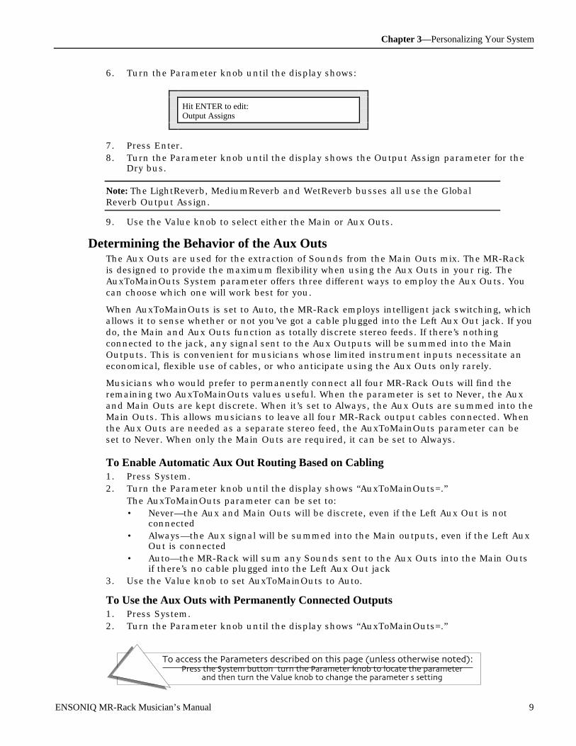
Chapter 3—Personalizing Your System
To access the Parameters described on this page (unless otherwise noted):Press the System button, turn the Parameter knob to locate the parameter,
and then turn the Value knob to change the parameter's setting.
ENSONIQ MR-Rack Musician’s Manual 9
6. Turn the Parameter knob until the display shows:
Hit ENTER to edit:Output Assigns
7. Press Enter.8. Turn the Parameter knob until the display shows the Output Assign parameter for the
Dry bus.
Note: The LightReverb, MediumReverb and WetReverb busses all use the GlobalReverb Output Assign.
9. Use the Value knob to select either the Main or Aux Outs.
Determining the Behavior of the Aux OutsThe Aux Outs are used for the extraction of Sounds from the Main Outs mix. The MR-Rackis designed to provide the maximum flexibility when using the Aux Outs in your rig. TheAuxToMainOuts System parameter offers three different ways to employ the Aux Outs. Youcan choose which one will work best for you.
When AuxToMainOuts is set to Auto, the MR-Rack employs intelligent jack switching, whichallows it to sense whether or not you’ve got a cable plugged into the Left Aux Out jack. If youdo, the Main and Aux Outs function as totally discrete stereo feeds. If there’s nothingconnected to the jack, any signal sent to the Aux Outputs will be summed into the MainOutputs. This is convenient for musicians whose limited instrument inputs necessitate aneconomical, flexible use of cables, or who anticipate using the Aux Outs only rarely.
Musicians who would prefer to permanently connect all four MR-Rack Outs will find theremaining two AuxToMainOuts values useful. When the parameter is set to Never, the Auxand Main Outs are kept discrete. When it’s set to Always, the Aux Outs are summed into theMain Outs. This allows musicians to leave all four MR-Rack output cables connected. Whenthe Aux Outs are needed as a separate stereo feed, the AuxToMainOuts parameter can beset to Never. When only the Main Outs are required, it can be set to Always.
To Enable Automatic Aux Out Routing Based on Cabling1. Press System.2. Turn the Parameter knob until the display shows “AuxToMainOuts=.”
The AuxToMainOuts parameter can be set to:• Never—the Aux and Main Outs will be discrete, even if the Left Aux Out is not
connected• Always—the Aux signal will be summed into the Main outputs, even if the Left Aux
Out is connected• Auto—the MR-Rack will sum any Sounds sent to the Aux Outs into the Main Outs
if there’s no cable plugged into the Left Aux Out jack3. Use the Value knob to set AuxToMainOuts to Auto.
To Use the Aux Outs with Permanently Connected Outputs1. Press System.2. Turn the Parameter knob until the display shows “AuxToMainOuts=.”
Chapter 3—Personalizing Your System
To access the Parameters described on this page (unless otherwise noted):Press the System button, turn the Parameter knob to locate the parameter,
and then turn the Value knob to change the parameter's setting.
10 ENSONIQ MR-Rack Musician’s Manual
The AuxToMainOuts parameter can be set to:• Never—the Aux and Main Outs will be kept as discrete stereo feeds• Always—the Aux signal will be summed into the Main Out stereo feed• Auto—the MR-Rack will sum any Sounds sent to the Aux Outs into the Main Outs
if there’s no cable plugged into the Left Aux Out jack3. Use the Value knob to set AuxToMainOuts=Never when you need to use the Aux Outs as a
discrete stereo feed, or to Always when using the Main Outs only.
A udit ioning Sounds on the M R - R ac kPressing the Audition button on the front panel will play a brief Sound audition demo for theSound on the currently selected part. The nature of the audition material is determined withthe setting of the Audition System parameter. When the Audition button is pressed, the MR-Rack can play octaves in any key, a major chord in any key, or a brief piece of music that’sappropriate to the currently selected Sound Type.
To Set What’s Heard When the Audition Button is Pressed1. Press System.2. Turn the Parameter knob until the display shows “Audition=.”3. The Audition parameter can be set to:
• Sound Type—a short composition appropriate to the currently selected Sound Typewill play when the Audition button is pressed
• A Octaves to G# Octaves—arpeggiated octaves up the keyboard will play when theAudition button is pressed
• A maj Chord to G# maj Chord—a major chord in a central pitch range will playwhen the Audition button is pressed
• A maj Arpeg to G# maj Arpeg—an arpeggiated major chord will play when theAudition button is pressed
4. Turn the Value knob to set the Audition type that you prefer.
Waking upYou can determine how the MR-Rack will “wake up” when you turn its power on. It canpower up a number of different ways, depending on the setting of the WakeUpModeparameter. The MR-Rack can turn on showing the last display—or “page”—you viewed whenyou turned the MR-Rack off. It can display the last Sound you selected. It can power upready for General MIDI. Or it can wake up with the →PlaySounds Performance and Part 1selected.
Note: The MR-Rack powers on with the Sounds LED lit, except when WakeUpMode isset to Last Page—in that case, the LED that was lit when the power was turned offwill be lit when the MR-Rack is turned back on.

Chapter 3—Personalizing Your System
To access the Parameters described on this page (unless otherwise noted):Press the System button, turn the Parameter knob to locate the parameter,
and then turn the Value knob to change the parameter's setting.
ENSONIQ MR-Rack Musician’s Manual 11
To Set How the MR-Rack Will Wake Up1. Press System.2. Turn the Parameter knob until the display shows “WakeUpMode=.”
The WakeUpMode parameter can be set to:• Last Page—the last page displayed when the MR-Rack was turned off will be
restored when it’s turned on• Last Sound—the last Sound selected when the MR-Rack was turned off will be
displayed when it’s turned on• GM—when the MR-Rack is turned on, it will be ready to operate with a General
MIDI sequencer. See "Using the MR-Rack to Play General MIDI Music" later in thischapter for further details on how the MR-Rack works with General MIDI
• Demo—when the MR-Rack is turned on, the Demo Performance and Part 1 will beselected, the AutoSelect FX Bus and PartParamReset parameters will be turned onand the Perf ProgChg parameter will be switched off (these parameters aredescribed elsewhere in this chapter)
3. Use the Value knob to set Wake Up Mode to the desired value.
P r ot e c t ing t he MR - R ac k’ s M e m or yWhen operating in the heat of creativity, it’s all too easy to inadvertently erase things you’drather preserve. The MR-Rack offers a special display prompt as a reality check duringactivities that could result in the loss of Sounds or Performances you don’t really want tolose. When saving, copying or initializing Sounds and Performances—or when initializingdata cards—the MR-Rack can be set to display:
System Write ProtectOn! ENTER overrides.
When you encounter this message, you can press Enter to continue what you were doing, orpress Exit to abort the procedure. The Write Protect System parameter allows you to enablethis feature if you feel you’d benefit from this double-check, or to disable it if you’d find theprompt unnecessary.
To Enable the Write Protect Prompt1. Press the System button.2. Use the Parameter knob to scroll until the display shows “Write Protect.”
• Off—the MR-Rack will execute the Save, Copy or Initialize procedure withoutdisplaying the Write Protect prompt
• Prompt—the MR-Rack will display the Write Protect prompt before it executes Save,Copy or Initialize procedures
3. Use the Value knob to set Write protect to Prompt.
To Disable the Write Protect Prompt1. Press the System button.2. Use the Parameter knob to scroll until the display shows “Write Protect.”
• Off—the MR-Rack will execute the Save, Copy or Initialize procedure withoutdisplaying the Write Protect prompt

Chapter 3—Personalizing Your System
To access the Parameters described on this page (unless otherwise noted):Press the System button, turn the Parameter knob to locate the parameter,
and then turn the Value knob to change the parameter's setting.
12 ENSONIQ MR-Rack Musician’s Manual
• Prompt—the MR-Rack will display the Write Protect prompt before it executes Save,Copy or Initialize procedures
3. Use the Value knob to set Write protect to Off.
Se t t ing th e St ak MI D I C hanne lThe MR-Rack introduces Staks, a convenient new way to create layers and keyboard splits.Staks are created by assigning two or more MR-Rack Parts—and the Sounds they use—tothe Stak MIDI channel. (See “Using Staks” in Chapter 4 for a fuller explanation of Staks.)
The Stak MIDI channel plays another important role in the operation of the MR-Rack. It canbe used to receive MIDI Program Changes that will select new Performances. This will occurwhen the Perf ProgChgRecv System parameter is enabled (see “Changing Performances ViaMIDI” below).
To Set the Stak MIDI Channel1. Press System.2. Turn the Parameter knob until the display shows “Stak MIDI Channel=.”
The Stak MIDI channel parameter may be set to any MIDI channel.3. Use the Value knob to select the Stak MIDI Channel you prefer.
Note: When this parameter is edited, all currently sounding voices on all Parts will bemuted.
A dj ust ing St ak C ohe r e nc e Since Staks contain multiple Parts, it may appear at times that they respond in a looselysynchronized manner. This can be a desirable effect, as it makes a Stak sound bigger. Inother situations, it’s not as musically appropriate. The Stak Coherence parameter allows youto instruct the MR-Rack to fire off all of the Staks voices precisely at once, for a tightersound. The Stak Coherence parameter can be used to tighten up any Parts that share MIDIchannels, even when they aren't assigned to the Stak MIDI channel.
Tip: When Stak Coherence=On, the overall timing of Parts that share MIDI channelsmay appear a bit sluggish as the MR-Rack perfectly lines up all of the notes beforesounding any of them. If you're sequencing, you can compensate for this slower,more synchronized response by shifting tracks slightly ahead of the beat.
To Perfectly Synchronize the Start of All Notes in a Stak1. Press System.2. Turn the Parameter knob until the display shows “Stak Coherence=.”
The Stak Coherence parameter may be set to:• Off—the Stak’s notes will sound normally• On—all notes in a Stak will sound at exactly the same time
3. Use the Value knob to set Stak Coherence to On.
Note: When this parameter is edited, all currently sounding voices on all Parts will bemuted.

Chapter 3—Personalizing Your System
To access the Parameters described on this page (unless otherwise noted):Press the System button, turn the Parameter knob to locate the parameter,
and then turn the Value knob to change the parameter's setting.
ENSONIQ MR-Rack Musician’s Manual 13
To Allow All Notes in a Stak to Start Normally1. Press System.2. Turn the Parameter knob until the display shows “Stak Coherence=.”
The Stak Coherence parameter may be set to:• Off—the Stak’s notes will sound normally• On—all notes in a Stak will sound at exactly the same time
3. Use the Value knob to set Stak Coherence to Off.
Note: When this parameter is edited, all currently sounding voices on all Parts will bemuted.
U sing MID I P r ogr am C han ges
Changing Performances Via MIDIThe MR-Rack allows you to send MIDI Program Changes on the Stak MIDI channel as ameans of selecting Performances. See “Setting the Stak MIDI Channel” above to learn how toset the Stak MIDI channel.
When the Perf ProgChgRecv System parameter is set to On, Program Changes received onthe Stak MIDI channel will select new Performances. Any Part whose MIDI channel is set toStak or to the same channel as the Stak MIDI channel will ignore Program Changes.
When ProgChgRecv is set to Off, Program Changes received on the Stak MIDI channel won’tselect Performances. They’ll also be ignored by any Parts whose MIDI channel is set to Stak.Parts which use the same channel as the Stak MIDI channel, however, will respond toProgram Changes received on this channel normally.
Note: The Perf ProgChgRecv parameter only affects Parts whose MIDI channels are setto Stak, or to the same channel as the Stak MIDI channel. Whether the PerfProgChgRecv parameter is set to On or Off, all other Parts receive MIDI ProgramChanges according to the settings of their ProgramChngeRecv and Bank Select RecvPart parameters (see Chapter 4 for details), and the setting of the GlobalBank&ProgChgRecv System parameter described below.
To Select New Performances With MIDI Program Changes1. Press System.2. Turn the Parameter knob until the display shows “Stak MIDI Channel=.”3. Use the Value knob to select the Stak MIDI Channel you prefer.4. Turn the Parameter knob until the display shows “Perf ProgChgRecv=.”
The Perf ProgChgRecv parameter can be set to:• On—Program Changes received on the Stak MIDI channel will select new
Performances• Off—Program Changes received on the Stak MIDI channel won’t select new
Performances.5. Turn the Value knob to set Perf ProgChgRecv to On6. Send Program Changes on the Stak MIDI channel to select Performances.

Chapter 3—Personalizing Your System
To access the Parameters described on this page (unless otherwise noted):Press the System button, turn the Parameter knob to locate the parameter,
and then turn the Value knob to change the parameter's setting.
14 ENSONIQ MR-Rack Musician’s Manual
Note: This parameter is overridden if Bank&ProgChgRecv (described below) is set toOff.
To Disable the Selection of Performances By Program Changes1. Press System.2. Turn the Parameter knob until the display shows “Perf ProgChgRecv=.”
The Perf ProgChgRecv parameter can be set to:• On—Program Changes received on the Stak MIDI channel will select new
Performances• Off—Program Changes received on the Stak MIDI channel won’t select new
Performances3. Turn the Value knob to set Perf ProgChgRecv to Off.
Any Parts set to the same channel as the Stak MIDI channel will respond to ProgramChanges received on the channel.
Note: This parameter is overridden if Bank&ProgChgRecv (described below) is set toOff.
Setting the Global Reception of MIDI Bank Selects and Program ChangesThe MR-Rack allows you to enable or disable its response to MIDI Bank Selects and ProgramChanges on a system-wide basis. The global Bank&ProgChgRecv System parameterfunctions as a master switch that can turn off the MR-Rack’s reception of Bank Selects andProgram Changes regardless of the ProgramChngeRecv and Bank Select Recv Partparameter settings, or the setting of the Perf ProgChgRecv System parameter describedearlier in this chapter. When Bank&ProgChgRecv=On, the above parameters control howeach Part responds to or ignores Bank Select and Program Change messages, and whetheror not Program changes received on the Stak MIDI channel will select new Performances.When Bank&ProgChgRecv is set to Off, the MR-Rack will ignore MIDI Bank Select andProgram Changes completely.
To Enable Reception of Bank Selects and Program Changes1. Press System.2. Turn the Parameter knob until the display shows “Bank&ProgChgRecv=.”
The Bank&ProgChgRecv parameter can be set to:• On—MIDI Bank Selects and Program Changes will be responded to according to
the settings of the ProgramChngeRecv and Bank Select Recv Part parameter andthe Perf ProgChgRecv System parameter
• Off—the MR-Rack will ignore MIDI Bank Selects and Program Changes3. Turn the Value knob to set Bank&ProgChgRecv to On.
To Disable Reception of Bank Selects and Program Changes1. Press System.2. Turn the Parameter knob until the display shows “Bank&ProgChgRecv=.”
The Bank&ProgChgRecv parameter can be set to:• On—MIDI Bank Selects and Program Changes will be responded to according to
the settings of the ProgramChngeRecv and Bank Select Recv Part parameter andthe Perf ProgChgRecv System parameter
Chapter 3—Personalizing Your System
To access the Parameters described on this page (unless otherwise noted):Press the System button, turn the Parameter knob to locate the parameter,
and then turn the Value knob to change the parameter's setting.
ENSONIQ MR-Rack Musician’s Manual 15
• Off—the MR-Rack will ignore MIDI Bank Selects and Program Changes3. Turn the Value knob to set Bank&ProgChgRecv to Off.
R e sponding to M ID I “P anic ” M e ssage sOccasionally MIDI devices get confused. As a result, some MIDI products are able to sendout “panic” messages to quickly bring MIDI chaos under control. The MR-Rack responds tothe following panic messages:
• Reset All Controllers (MIDI controller #121)• All Notes Off (MIDI controller #123)• All Sounds Off (MIDI controller #120)
Setting the MR-Rack’s Response to Reset All Controllers MIDI MessagesThe ResetControlRecv System parameter allows you to determine how the MR-Rack willrespond to Reset All Controllers MIDI messages. When it’s set to On, and a Part receives aReset All Controllers message on its MIDI channel, it will return all of its real-timecontrollers and any parameters that respond to MIDI controllers to their default values,clearing up any hung values or unexpected settings. When ResetControlRecv is set to Off, noMR-Rack Parts will respond to Reset All Controllers messages. For more information on theMR-Rack's response to Reset All Controllers messages, see "Reset All Controllers (MIDIcontroller 121) Reception Behavior" in Chapter 9.
To Set the Response to Reset All Controllers Messages1. Press System.2. Turn the Parameter knob until the display shows “ResetControlRecv=.”
The ResetControlRecv parameter can be set to:• Off—the MR-Rack will ignore Reset All Controllers MIDI messages• On—any Part receiving a Reset All Controllers message on its MIDI channel will
reset its real-time controllers and any parameters that respond to MIDI controllersto default values
3. Turn the Value knob to set ResetControlRecv to the desired value.
Setting the MR-Rack’s Response to All Notes Off MIDI MessagesThe MR-Rack can respond to All Notes Off and All Sounds Off MIDI control messages. Whena Part receives either of these on its MIDI channel, it silences any of its notes that arecurrently sounding. The AllNotesOff Recv System parameter is a combined filter for both ofthese messages. When it’s set to On, the MR-Rack will respond to them—when it’s set to Off,it will ignore them.
To Set the MR-Rack’s Response to All Notes Off Messages1. Press System.2. Turn the Parameter knob until the display shows “AllNotesOff Recv=.”
This AllNotesOff Recv parameter is a combined All Notes Off (MIDI control #123) and AllSounds Off (MIDI control #120) reception filter. It can be set to:• Off—the MR-Rack will ignore the All Notes Off and All Sounds Off MIDI messages• On—any Part receiving an All Notes Off and/or All Sounds Off MIDI message on its
MIDI channel will silence all of its currently-sounding notes3. Turn the Value knob to set AllNotesOff Recv to the desired value.

Chapter 3—Personalizing Your System
To access the Parameters described on this page (unless otherwise noted):Press the System button, turn the Parameter knob to locate the parameter,
and then turn the Value knob to change the parameter's setting.
16 ENSONIQ MR-Rack Musician’s Manual
U sing MID I SysEx
Enabling and Disabling System Exclusive CommunicationThe MR-Rack can use MIDI System Exclusive (or “SysEx”) messages to communicate withcomputer programs—such as the Unisyn sound editor ENSONIQ will provide you with whenyou send in your completed warranty card—and as a means of archiving the contents of itsmemory to an external storage device such as a floppy disk drive or a computer’s hard drive.SysEx data is a special kind of MIDI data which doesn’t require a specific MIDI channel. TheSysEx Recv System parameter globally enables or disables the MR-Rack’s MIDI SysExcommunication capabilities, with exception of SysEx data dumps, described in Chapter 6,which can always be performed. (If you’d like to learn more about MIDI SysEx, see “What IsMIDI” in Chapter 9.)
To Enable or Disable SysEx Communication1. Press System.2. Turn the Parameter knob until the display shows “SysEx Recv=.”
The SysEx Recv parameter can be set to:• Off—the MR-Rack will not receive or transmit MIDI SysEx data, except for the
always-enabled SysEx data dumps described in Chapter 6• On—the MR-Rack will receive and transmit MIDI SysEx data
3. Use the Value knob to set SysEx Recv to the desired value.
Using SysEx Device IDsEvery MIDI product has its own SysEx identity—but what if you’ve got several MR-Racksconnected at the same time? Each one of them can be assigned its own SysEx Device IDnumber, from 000 to 127. In this way, each MR-Rack can identify the MIDI SysEx data thatit’s meant to receive. Of course, it’s vital that no two MR-Racks share the same SysEx DeviceID number.
Note: The SysEx ID number is not a MIDI channel—SysEx data doesn’t require one.
To Set the MR-Rack’s SysEx Device ID Number1. Press System.2. Turn the Parameter knob clockwise to “SysEx Device ID=.”
The SysEx Device ID parameter can be set to any number from 000 to 127.3. Use the Value knob to select the System Exclusive Device ID number you want to use
for this MR-Rack.
Note: When performing SysEx dumps from the MR-Rack using the Dump commandsdescribed in Chapter 6, make note of your MR-Rack’s current SysEx Device IDnumber. This number is embedded in the dumped data. Your MR-Rack will need tobe set to this ID number when you want to re-transmit the data back into the MR-Rack.
Se t t ing Up N e w R e al- Tim e Cont r olle r s

Chapter 3—Personalizing Your System
To access the Parameters described on this page (unless otherwise noted):Press the System button, turn the Parameter knob to locate the parameter,
and then turn the Value knob to change the parameter's setting.
ENSONIQ MR-Rack Musician’s Manual 17
Each Part in the MR-Rack can respond to the following real-time MIDI controllers andmessages:
• Data Entry Slider• Pitch Bend Wheel• Mod Wheel• Foot Pedal• Sustain/Sostenuto pedals• MIDI Volume messages• MIDI Pan messages• MIDI Expression messages
In addition, the MR-Rack allows you to define four additional real-time MIDI controllers:System Controller 1, System Controller 2, System Controller 3 and System Controller 4.These can be assigned to respond to any legitimate MIDI controller. Any one of the four canbe used to modulate the MR-Rack’s Sounds or Effects. See Chapter 5 to learn how to useone of these System Controllers as an Effect modulator. See Chapter 9 to learn about usingthe System Controllers to modulate elements within MR-Rack sounds.
Note: Each Part has four parameters which determine whether or not its Soundor—when the Part is designated as the Insert Control Part—its Insert Effect willrespond to each of the four controllers. See “Working With System MIDI Controllers”in Chapter 4 for details.
To Set Up the Four System Controllers1. Press System.2. Turn the Parameter knob until the display shows the name of the System Controller
you’d like to use:• CTRL1—System Controller 1• CTRL2—System Controller 2• CTRL3—System Controller 3• CTRL4—System Controller 4
3. After selecting one of the four System Controllers, use the Value knob to locate the MIDIcontroller number you’d like to assign to the System Controller you’ve selected.

Chapter 3—Personalizing Your System
To access the Parameters described on this page (unless otherwise noted):Press the System button, turn the Parameter knob to locate the parameter,
and then turn the Value knob to change the parameter's setting.
18 ENSONIQ MR-Rack Musician’s Manual
Note: If more than one System Controller is assigned to the same MIDI controllernumber, only the lower-numbered System Controller will respond to the MIDIcontroller.
When the MR-Rack is shipped from the factory:
• CTRL1 is assigned to Breath Controller (MIDI controller #002).• CTRL2 is assigned to FXControl1 (MIDI controller #012).• CTRL3 is assigned to PatchSelct (MIDI controller #070).• CTRL4 is assigned to Timbre (MIDI controller #071).
Le ar ning How M uc h RA M is Avai lable f or N e w SoundsUnisyn, a computer-based, external sound editing program, can be used to create and edityour own Sounds. ENSONIQ will provide you a copy of the Unisyn MR-Rack Editor whenyou send in your completed MR-Rack warranty card. See the Unisyn documentation to learnhow to install it on your computer. Chapter 9 describes using the Unisyn editor to createand edit MR-Rack Sounds.
When you create a new Sound, you’ll need to know if there’s enough memory available inthe MR-Rack to accommodate it. Each MR-Rack Sound can contain up to 16 layers. Eachbank can contain up to 361 layers. The amount of free internal memory (RAM) in the MR-Rack is expressed as the number of layers still available in its RAM Sound bank.
To Find Out How Much Free Memory (RAM) is Available in the MR-RackTo get an idea of how much RAM memory is available for creating your sounds, the MR-Rack displays the amount of free Sound layers.
1. Press System.2. Turn the Parameter knob until the display shows “Free RAM:.”
This read-only display shows the number of free Sound layers still available in RAM.
Le ar ning the N um be r of Banks on a Dat a C ar dData cards—or PCMCIA cards, as they’re known throughout the computer and musicalinstrument industries—are credit-card-sized memory cards. A PCMCIA card is an easy wayto instantly access new MR-Rack Sounds, Performances, and demos. MR-Rack-formattedcards may be inserted into the Data Card slot on the MR-Rack ’s front panel. There are twotypes of PCMCIA cards that can be used with the MR-Rack.
ROM cards provide new Sounds, Performances and demos in a read-only format that can’tbe erased. Each ENSONIQ MRC Series ROM Sound card offers two Banks of new Sounds,Performances and demos.
SRAM cards—for saving your own Sounds and Performances. These cards vary in size, from512k up to 2 MB. The number of banks on a card depends on the card’s size:
• 512k cards can hold 4 Banks of Sounds and Performances• 1 MB cards can hold 9 Banks of Sounds and Performances• 2 MB cards can hold 18 Banks of Sounds and Performances
Each card bank is equal in size to the MR-Rack’s RAM memory—with a maximum

Chapter 3—Personalizing Your System
To access the Parameters described on this page (unless otherwise noted):Press the System button, turn the Parameter knob to locate the parameter,
and then turn the Value knob to change the parameter's setting.
ENSONIQ MR-Rack Musician’s Manual 19
capacity of 361 Sound layers—and can hold the same number of Sounds (up to 128)and Performances (32).
SRAM Cards can be purchased inexpensively from computer supply stores or fromENSONIQ, whose MC-512 SRAM Card offers 4 Sound/Performance banks.
For more information, see “Using PCMCIA Data Cards” in Chapter 7.
Note: The MR-Rack will not accept Flash PCMCIA cards, or any special-functionPCMCIA cards, such as modem cards for portable computers, etc.
To Learn How Many Banks are on the Currently Installed Card1. Insert an MR-Rack formatted PCMCIA data card into the Data Card slot with its label
side up and its connection edge toward the MR-Rack.To learn how to format a PCMCIA SRAM card, see Chapter 7.The display will momentarily show:
PCMCIA Card InsertedRegistering...
2. Press System.3. Turn the Parameter knob until the display shows “CRD Size:”
This read-only display shows the number of banks on the installed card. If no card isinstalled, the display will show “ No card!” in place of the bank number.
Ide nt if ying Inst alle d Wave Expansion Boar dsThe MR-Rack can accommodate up to three ENSONIQ EXP Series Wave Expansion Boards.Wave Expansion Boards provide new wave data for the MR-Rack, as well as new Sounds,Performances and demos. For a full description of how to install and use ENSONIQ EXPSeries Wave Expansion Boards, see “Using ENSONIQ EXP Wave Expansion Boards” inChapter 7.
The MR-Rack provides three displays which can identify any EXP Wave Expansion boardsyou have installed.
To Identify an Installed Expansion Board1. Press the System button.2. Turn the Parameter knob until the display shows:
System parameters:WaveEXP1:xxxxxxxxxxx
iExpansion Board name
When an Expansion Board is installed, this read-only display will show the name of theExpansion Board located in the first slot.

Chapter 3—Personalizing Your System
To access the Parameters described on this page (unless otherwise noted):Press the System button, turn the Parameter knob to locate the parameter,
and then turn the Value knob to change the parameter's setting.
20 ENSONIQ MR-Rack Musician’s Manual
3. Turning the Parameter knob two more times will reveal two more displays which showthe names of the Expansion Boards in Wave EXP Slots 2 and 3 (if they’re installed).
If there are no Expansion Boards installed, the display will show “WaveEXP1= **EMPTY**.”
Note: If you’ve installed Expansion Boards and the MR-Rack appears not to berecognizing them, carefully repeat the instructions in “How To Install an ExpansionBoard” from Chapter 7. If the MR-Rack still doesn’t recognize the Expansion Board,call ENSONIQ Customer Service at 610-647-3930.
U sing the M R - R ac k t o Play Ge ne r al MID I M usic General MIDI is an agreed-upon set of sounds and protocols which aims to ensure that, nomatter what brand or model General MIDI instrument you use in conjunction with yourpersonal computer to play back a General MIDI recording, the music is guaranteed to soundgood. For a more detailed description of General MIDI, see “What Is General MIDI?” found inChapter 9.
To Use the MR-Rack as a General MIDI Sound Module1. Press System.2. Press System again. The display shows:
System parameters:Hit ENTER for GM!
3. If you’d like to continue, press Enter. If not, press Exit.Pressing Enter selects the ROM GM performance, selects Part 1, and sets PerfProgChgRecv=Off.
The MR-Rack is now prepared to operate in conjunction with General MIDI. If your GMsequencer’s MIDI Out is connected to the MR-Rack’s MIDI In, you’re ready to start themusic!
To Set the MR-Rack to Power Up Ready for General MIDI Music1. Press System.2. Turn the Parameter knob until the display shows “WakeUpMode=.”
The WakeUpMode parameter can be set to:• Last Page—the last page displayed when the MR-Rack was turned off will be
restored when it’s turned on• Last Sound—the last Sound selected when the MR-Rack was turned off will be
displayed when it’s turned on• GM—when the MR-Rack is turned on, it will be ready to operate with a General
MIDI sequencer• Demo— when the MR-Rack is turned on, the Demo Performance and Part 1 will be
selected, and Program Changes received on the Stak MIDI channel will choose newPerformances
3. Use the Value knob to set WakeUpMode to GM.
To Reset the MR-Rack for Use with Non-General MIDI Music
Chapter 3—Personalizing Your System
To access the Parameters described on this page (unless otherwise noted):Press the System button, turn the Parameter knob to locate the parameter,
and then turn the Value knob to change the parameter's setting.
ENSONIQ MR-Rack Musician’s Manual 21
1. Press the Performance button.2. Use the Sound Type and Sound Name knobs to select a new Performance.
When the MR-Rack prepares itself for General MIDI music, it alters the settings of anumber of System parameters.
3. Check the settings of the Part Param Reset, PitchBendMode, AutoSelect FXBus, PerfProgChgRecv, Bank&ProgChgRecv, ResetControlRecv, AllNotesOff Recv and SysExSystem parameters to see if you’d like to reset them.
MR-Rack General MIDI Details for the CuriousGeneral MIDI is designed to be extremely easy to use, and requires no backgroundknowledge of its workings. However, for MR-Rack users who are interested, here’s whathappens when you “Hit ENTER for GM!”
• The MR-Rack selects a General MIDI Performance whose Parts 1-16 are set to MIDIchannels 1-16, respectively. These Parts are pointed towards the MR-Rack’s banks ofGeneral MIDI Sounds, and their Bank Select reception has been disabled so that they’llonly be able to select Sounds from these banks when they receive Program Changes.The GM Standard drum kit is assigned to Part 10.
• The System Perf ProgChgRecv parameter is set to Off to ensure that Program Changesdon’t unintentionally select a new, non-GM Performance.
• The System AutoSelect FX Bus parameter is set to Off to allow General MIDI Effectchange messages to control the MR-Rack’s chorus and reverb.
• The Part Param Reset parameter is set to Off to protect various Part parameters that arepreset for General MIDI.
• PitchBendMode is set to Prog so that the GM Sounds are allowed to interpret PitchBend messages as they’re programmed to, in accordance with General MIDI.
• Bank&ProgChgRecv is set to On so that the MR-Rack can respond to General MIDIProgram Changes.
• ResetControlRecv and AllNotesOff Recv are set to On so that the MR-Rack can respondto MIDI panic messages.
• SysEx Recv is set to On so that you can return the MR-Rack to its original General MIDIsettings any time you like, via a General MIDI On SysEx message.
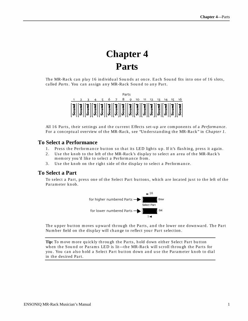
Chapter 4—Parts
ENSONIQ MR-Rack Musician’s Manual 1
Ch apt e r 4P art s
The MR-Rack can play 16 individual Sounds at once. Each Sound fits into one of 16 slots,called Parts. You can assign any MR-Rack Sound to any Part.
All 16 Parts, their settings and the current Effects set-up are components of a Performance.For a conceptual overview of the MR-Rack, see “Understanding the MR-Rack” in Chapter 1.
To Select a Performance1. Press the Performance button so that its LED lights up. If it’s flashing, press it again.2. Use the knob to the left of the MR-Rack’s display to select an area of the MR-Rack’s
memory you’d like to select a Performance from.3. Use the knob on the right side of the display to select a Performance.
To Select a PartTo select a Part, press one of the Select Part buttons, which are located just to the left of theParameter knob.
Enter
Select Part
Exit
16
1
for higher-numbered Parts
for lower-numbered Parts
The upper button moves upward through the Parts, and the lower one downward. The PartNumber field on the display will change to reflect your Part selection.
Tip: To move more quickly through the Parts, hold down either Select Part buttonwhen the Sound or Params LED is lit—the MR-Rack will scroll through the Parts foryou. You can also hold a Select Part button down and use the Parameter knob to dialin the desired Part.
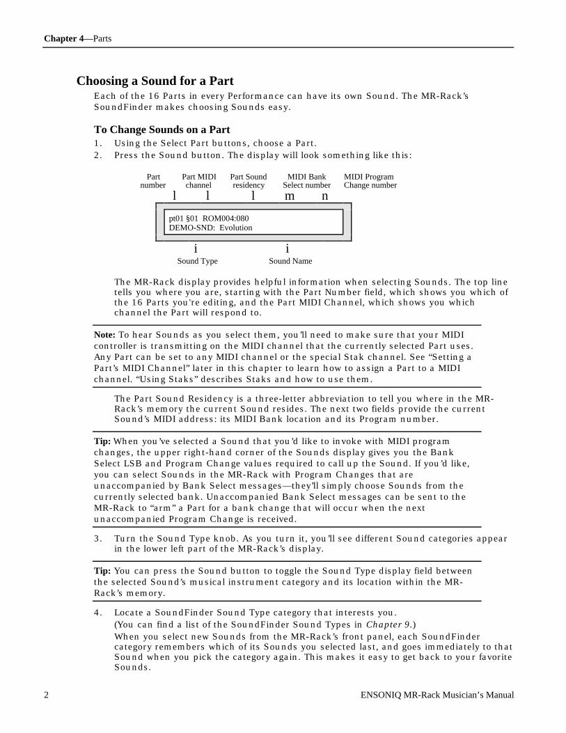
Chapter 4—Parts
2 ENSONIQ MR-Rack Musician’s Manual
Choosing a Sound for a PartEach of the 16 Parts in every Performance can have its own Sound. The MR-Rack’sSoundFinder makes choosing Sounds easy.
To Change Sounds on a Part1. Using the Select Part buttons, choose a Part.2. Press the Sound button. The display will look something like this:
Partnumber
Part MIDIchannel
Part Soundresidency
MIDI BankSelect number
MIDI ProgramChange number
l l l m n
pt01 §01 ROM004:080DEMO-SND: Evolution
i iSound Type Sound Name
The MR-Rack display provides helpful information when selecting Sounds. The top linetells you where you are, starting with the Part Number field, which shows you which ofthe 16 Parts you're editing, and the Part MIDI Channel, which shows you whichchannel the Part will respond to.
Note: To hear Sounds as you select them, you’ll need to make sure that your MIDIcontroller is transmitting on the MIDI channel that the currently selected Part uses.Any Part can be set to any MIDI channel or the special Stak channel. See “Setting aPart’s MIDI Channel” later in this chapter to learn how to assign a Part to a MIDIchannel. “Using Staks” describes Staks and how to use them.
The Part Sound Residency is a three-letter abbreviation to tell you where in the MR-Rack’s memory the current Sound resides. The next two fields provide the currentSound’s MIDI address: its MIDI Bank location and its Program number.
Tip: When you’ve selected a Sound that you’d like to invoke with MIDI programchanges, the upper right-hand corner of the Sounds display gives you the BankSelect LSB and Program Change values required to call up the Sound. If you’d like,you can select Sounds in the MR-Rack with Program Changes that areunaccompanied by Bank Select messages—they’ll simply choose Sounds from thecurrently selected bank. Unaccompanied Bank Select messages can be sent to theMR-Rack to “arm” a Part for a bank change that will occur when the nextunaccompanied Program Change is received.
3. Turn the Sound Type knob. As you turn it, you’ll see different Sound categories appearin the lower left part of the MR-Rack’s display.
Tip: You can press the Sound button to toggle the Sound Type display field betweenthe selected Sound’s musical instrument category and its location within the MR-Rack’s memory.
4. Locate a SoundFinder Sound Type category that interests you.(You can find a list of the SoundFinder Sound Types in Chapter 9.)When you select new Sounds from the MR-Rack’s front panel, each SoundFindercategory remembers which of its Sounds you selected last, and goes immediately to thatSound when you pick the category again. This makes it easy to get back to your favoriteSounds.

Chapter 4—Parts
ENSONIQ MR-Rack Musician’s Manual 3
5. Turn the Sound Name knob to choose a Sound of the selected type.Sound names appear on the lower right-hand portion of the display. When you select anew Sound, any notes currently playing on the selected Part will be silenced.
6. To listen to the Sound you’ve selected, send MIDI data to the MR-Rack on the MIDIchannel to which the Part is assigned, as shown in the display above. Any Part can beedited to use any MIDI channel.
Note: If you hear more than one Sound playing as you listen to Sounds, it may bethat another Part is set to the same MIDI channel you’re using for the currentlyselected Part. Press the Select Part buttons to go through the other Parts and see ifthere’s a conflict. If necessary, change the other Parts to a MIDI channel you’re notusing, or mute the unwanted Part. (See “Setting a Part’s MIDI Channel” or “Mutingand Soloing Parts” later in this chapter).
A Note About Sounds and EffectsMost MR-Rack Sound are programmed with an Effect. Each Performance offers three typesof Effects—an Insert Effect, Global Chorus and Global Reverb—and Parts may be routed toany of the three, or left dry. Sounds often sound best when they’re on a Part that’s beendesignated as the current Performance’s Insert Control Part. Chapter 5 provides a fullexplanation of the MR-Rack Effects.
To Designate a Part as the Insert Control Part1. Press the Effects button.2. Turn the Parameter knob until the bottom line of the display shows the InsertContrlPart
parameter.3. Turn the Value knob to select the number of the Part you’d like to use as the current
Performance’s Insert Control Part.
Auditioning SoundsThe MR-Rack offers several convenient ways to audition Sounds. You can hear a briefdemonstration of the Sound playing a piece of music appropriate to its SoundFinder SoundType category, playing octaves in any key, or playing a major chord, also in any key. Asshipped from the factory, the MR-Rack will play a piece of music appropriate to thecurrently selected Sound Type. To learn how to change what you’ll hear when you audition aSound, see the Audition parameter in Chapter 3 .
Note: Pressing the Audition button will have no effect when the Sound is being usedon a Part that’s muted.
To Audition a Sound• Press the Audition button.
To Stop the Auditioning of a Sound• Press the Audition button again.
You can also turn the Sound Type knob or press any of the MR-Rack's buttons to stopauditioning.
Editing PartsEach Part offers a number of options for determining how it—and any Sound the Partuses—will behave. These options are called Part parameters. When you edit a Partparameter’s setting, you are editing its value.
To access Part parameters, press the Params button. When you press the Params button,
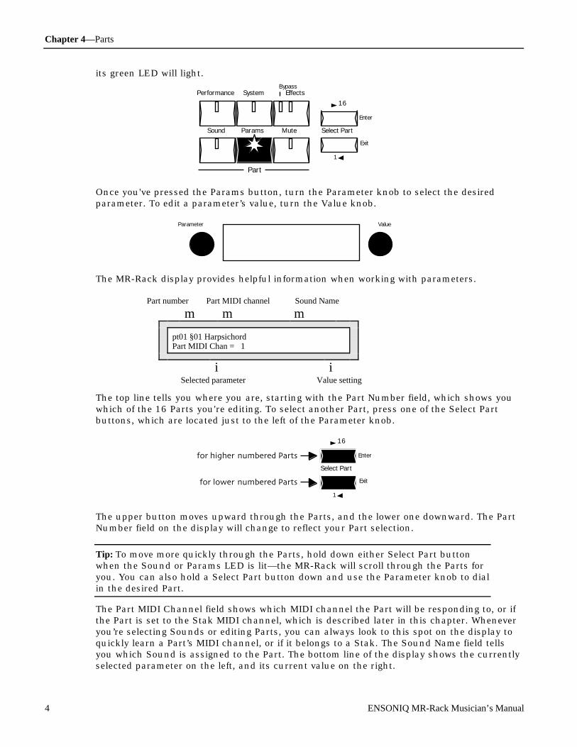
Chapter 4—Parts
4 ENSONIQ MR-Rack Musician’s Manual
its green LED will light.
Performance System Effects
Enter
Select Part
Exit
Sound Params Mute
Part
Bypass
16
1
Once you've pressed the Params button, turn the Parameter knob to select the desiredparameter. To edit a parameter’s value, turn the Value knob.
Parameter Value
The MR-Rack display provides helpful information when working with parameters.
Part number Part MIDI channel Sound Name
m m m
pt01 §01 HarpsichordPart MIDI Chan = 1
i iSelected parameter Value setting
The top line tells you where you are, starting with the Part Number field, which shows youwhich of the 16 Parts you're editing. To select another Part, press one of the Select Partbuttons, which are located just to the left of the Parameter knob.
Enter
Select Part
Exit
16
1
for higher-numbered Parts
for lower-numbered Parts
The upper button moves upward through the Parts, and the lower one downward. The PartNumber field on the display will change to reflect your Part selection.
Tip: To move more quickly through the Parts, hold down either Select Part buttonwhen the Sound or Params LED is lit—the MR-Rack will scroll through the Parts foryou. You can also hold a Select Part button down and use the Parameter knob to dialin the desired Part.
The Part MIDI Channel field shows which MIDI channel the Part will be responding to, or ifthe Part is set to the Stak MIDI channel, which is described later in this chapter. Wheneveryou’re selecting Sounds or editing Parts, you can always look to this spot on the display toquickly learn a Part’s MIDI channel, or if it belongs to a Stak. The Sound Name field tellsyou which Sound is assigned to the Part. The bottom line of the display shows the currentlyselected parameter on the left, and its current value on the right.

Chapter 4—Parts
To access the Parameters described on this page (unless otherwise noted):press the Params button, turn the Parameter knob to locate the parameter,
and then turn the Value knob to change the parameter's setting.
ENSONIQ MR-Rack Musician’s Manual 5
U nde r st anding Par t P ar am e t e r s
The Two Kinds of Part ParametersEach Part contains a broad selection of settings called Part parameters. These parametersfall into two general types of settings:
• Some Part parameters control the behavior of the Part, for example, the MIDI channelon which the selected Part will receive MIDI data, and whether or not the Part willrespond to MIDI Bank Select and Program Change messages and various other MIDIcontrollers
• Some Part parameters determine the behavior of the Part’s Sound while it’s being usedby the Part—a broad collection of Sound-modifying tools lets each Part use its Sound ina manner of your choosing.
Parts Parameters and SoundsIt’s important, when editing Part parameters, to understand the relationship between Partsand the Sounds they use. You can think of a Part as a bin—or a slot, as mentionedabove—that contains a Sound. When you adjust Part parameters to change the way aSound is heard, the Sound is altered only for as long as it’s being used by the Part you’reediting. You’re not permanently altering the Sound itself—you’re merely changing the waythe Part uses the Sound.
When a Part Has Been EditedSince the MR-Rack’s 16 Parts collectively comprise a Performance, whenever you edit aPart’s parameters, you’re altering the currently selected Performance. Changes you make toany of the 16 Parts are temporary until you save this edited Performance to the MR-Rack’smemory or a PCMCIA card. This is accomplished through the use of the Save:ThisPerformance command, described below in “Saving a Performance.”
If you’ve used a Part’s parameters to alter the nature of a Sound it’s using, and would like tosave those changes into the Sound itself, the MR-Rack allows you to do so by using theSave: ThisPart’sSound command, described below in “Saving a Part’s Sound.” By saving aPart’s Sound, the changes you’ve made to the Sound will be heard whenever the Sound isselected for use by any Part.
Working With an Edited Performance That Hasn’t Yet Been SavedWhen the Performance button is pressed after a Part parameter has been changed—or whena parameter setting is changed via MIDI while the Performance is being displayed—the word“EDITED” appears on the display to signify that the Performance has been altered.(“EDITED” also appears in the Performance display when an Effect has been edited; seeChapter 5.)
m
perf **EDITED**ROM-PERF:~PlaySounds
Before you save a Performance, the MR-Rack temporarily stores your changes in an editbuffer. You can listen to other Performances without losing these edits, as long as you don’t

Chapter 4—Parts
To access the Parameters described on this page (unless otherwise noted):press the Params button, turn the Parameter knob to locate the parameter,
and then turn the Value knob to change the parameter's setting.
6 ENSONIQ MR-Rack Musician’s Manual
do any further editing. Once you make any further changes, those edits will be placed in thebuffer, wiping out your earlier work. To truly protect your edits, you’ll need to save yourPerformance, or the Sound—or Sounds—you’ve been working with.
Warning: If a single Performance is transmitted to the MR-Rack via SysEx, it will beplaced in the Performance edit buffer, replacing any edited Performance you havethere. (See Chapter 6 for more information on MIDI SysEx transmission andreception.)
To Recall an Edited Performance• Press the Performance button twice if it’s not already lit, or once if it is.
The Performance button’s LED will begin blinking on and off and the display will flash“**EDITED**.” You can now hear your edited Performance.
Saving a PerformanceWhen you save a Performance, you save the current Part parameter settings for all 16Parts—including which Sounds they use—and the current Effects setup (Chapter 5describes the MR-Rack’s Effects).
To Save a Performance1. Press the Performance button and select the Performance that you want to save.2. Press the Save button.3. Turn the Parameter knob all the way counter clockwise.4. Turn the Value knob all the way counterclockwise. The display shows:
Hit ENTER to:Save:ThisPerformance
5. Press the Enter button.If the System Write Protect parameter is set to Prompt, the display will show:
System Write ProtectOn! ENTER Overrides.
This display is offered as a double-check for you to make sure you really want to savethis Performance. If you’d like to avoid this prompt in the future, see “Protecting theMR-Rack’s Memory” in Chapter 3.
6. If you’d like to cancel the operation, press the Exit button. If you’d like to proceed, pressthe Enter button. The display now allows you to name your Performance:

Chapter 4—Parts
To access the Parameters described on this page (unless otherwise noted):press the Params button, turn the Parameter knob to locate the parameter,
and then turn the Value knob to change the parameter's setting.
ENSONIQ MR-Rack Musician’s Manual 7
Left knob function Right knob function
m m
LEFT:pos RIGHT:charNew Name=FinePerform
iNew Performance Name
The Parameter knob (left) is used to select the character position within the name. Youwill know which character is selected because the position in the display will beunderlined. Turning the knob clockwise moves the location to the right, andcounterclockwise moves it to the left. The Value knob (right) is used to select the alpha-numeric character for that location.
7. Use the Parameter and Value knobs to select a name for your Performance.8. When you’ve named your Performance, press the Enter button.9. Use the Parameter knob to select either:
• RAM—to save the Performance to the MR-Rack’s internal RAM memory.• CRD—to save the Performance to an installed data card (see “Formatting a PCMCIA
Card” below for instructions on how to prepare a data card for storage).10. Use the Value knob to select a specific location for your Performance.11. When you’ve selected a location for your Performance, press the Enter button. The MR-
Rack will provide confirmation of your Save operation’s success, and then display thenewly-saved Performance.
Warning: When saving a Performance to a data card, avoid removing the card from itsslot until the saving procedure is complete—doing so may result in corrupted data onthe card and/or in the MR-Rack’s internal memory.
Saving a Part’s SoundWhen you save a Part’s Sound, all of the selected Part’s parameter settings affecting the wayits Sound is heard become permanent attributes of the Sound.
To Save a Part’s Sound1. Press the Sound button, and use the Select Part buttons to find the Sound that you
want to save.2. Press the Save button.3. Turn the Parameter knob all the way counterclockwise.4. Turn the Value knob until the display shows:
Hit ENTER to:Save:ThisPart’ sSound
5. Press the Enter button.

Chapter 4—Parts
To access the Parameters described on this page (unless otherwise noted):press the Params button, turn the Parameter knob to locate the parameter,
and then turn the Value knob to change the parameter's setting.
8 ENSONIQ MR-Rack Musician’s Manual
If the System Write Protect parameter is set to Prompt, the display will show:
System Write ProtectOn! ENTER Overrides.
This display is offered as a double-check for you to make sure you really want to savethis Sound. If you’d like to avoid this prompt in the future, see “Protecting the MR-Rack’s Memory” in Chapter 3.
6. If you’d like to cancel the operation, press the Exit button. If you’d like to proceed, pressthe Enter button. The display now allows you to name your Sound:
Left knob function Right knob function
m m
LEFT:pos RIGHT:charNew Name=MySoundName
iNew Sound Name
The Parameter knob (left) is used to select the character position within the name. Youwill know which character is selected because the position in the display will beunderlined. Turning the knob clockwise moves the location to the right, andcounterclockwise moves it to the left. The Value knob (right) is used to select the alpha-numeric character for that location.
7. Use the Parameter and Value knobs to select a name for your Sound.8. When you’ve named your Sound, press the Enter button.9. Use the Value knob to select a SoundFinder type for your Sound. This feature allows
you to easily locate similar Sounds. For more information about using SoundFinder, seeChapter 1. For a complete list of SoundFinder types, see Chapter 9.
10. When you’ve defined a SoundFinder type, press the Enter button.11. Use the Parameter knob to select either:
• RAM—to save the Sound to the MR-Rack’s internal RAM memory.• CRD—to save the Sound to an installed data card (see “Formatting a PCMCIA
Card” below for instructions on how to prepare a data card for storage).12. Use the Value knob to select a specific location for your Sound.13. When you’ve selected a location for your Sound, press the Enter button. The display
momentarily confirms the successful completion of your command, and selects thenewly-saved Sound. All of the Part’s Sound-related parameters are reset to theirnominal values.
Warning: When saving a Sound to a data card, avoid removing the card from its slotuntil the saving procedure is complete—doing so may result in corrupted data on thecard and/or in the MR-Rack’s internal memory.
If you’d like to install the newly-saved Sound as a SoundFinder category’s favorite, turn theValue knob one tick clockwise or counter-clockwise and back to register the new Sound asthe current category’s favorite.
The Structure of MR-Rack Sounds
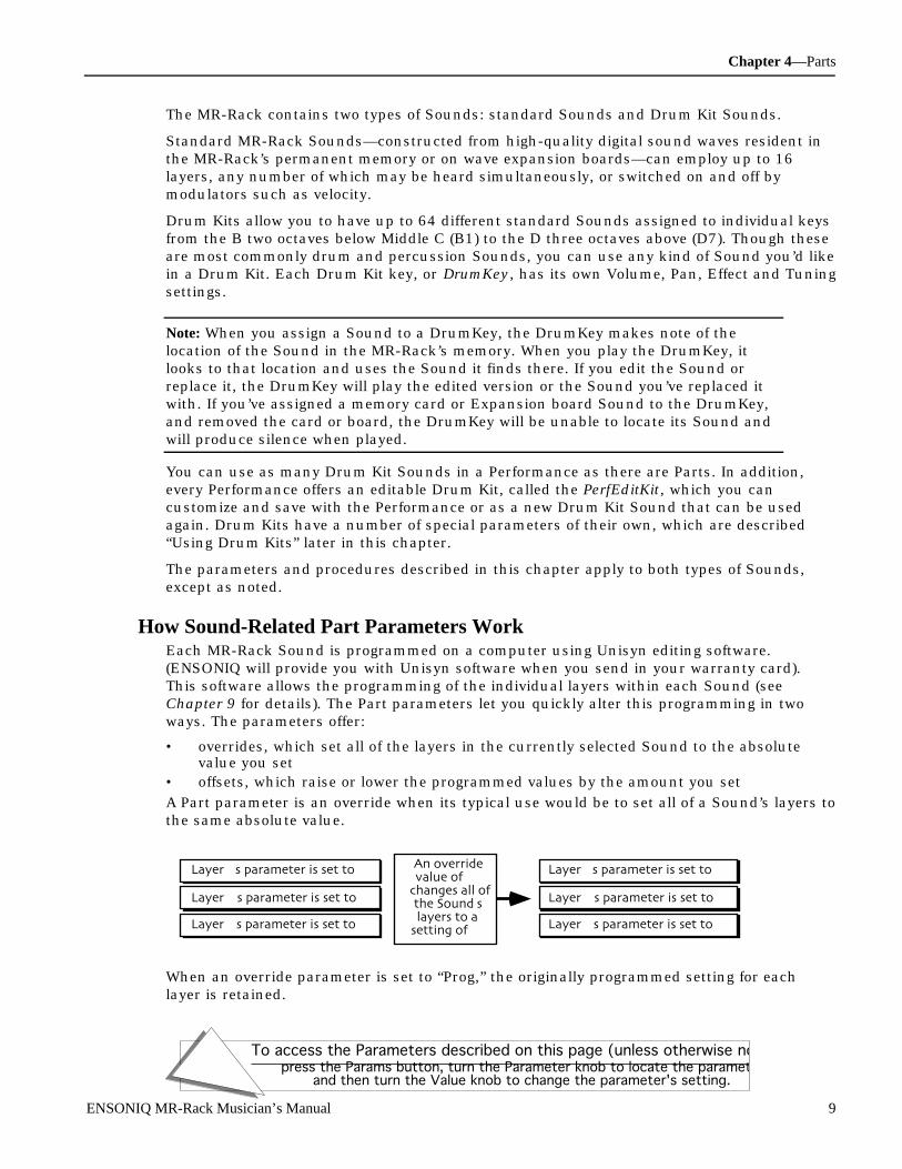
Chapter 4—Parts
To access the Parameters described on this page (unless otherwise noted):press the Params button, turn the Parameter knob to locate the parameter,
and then turn the Value knob to change the parameter's setting.
ENSONIQ MR-Rack Musician’s Manual 9
The MR-Rack contains two types of Sounds: standard Sounds and Drum Kit Sounds.
Standard MR-Rack Sounds—constructed from high-quality digital sound waves resident inthe MR-Rack’s permanent memory or on wave expansion boards—can employ up to 16layers, any number of which may be heard simultaneously, or switched on and off bymodulators such as velocity.
Drum Kits allow you to have up to 64 different standard Sounds assigned to individual keysfrom the B two octaves below Middle C (B1) to the D three octaves above (D7). Though theseare most commonly drum and percussion Sounds, you can use any kind of Sound you’d likein a Drum Kit. Each Drum Kit key, or DrumKey, has its own Volume, Pan, Effect and Tuningsettings.
Note: When you assign a Sound to a DrumKey, the DrumKey makes note of thelocation of the Sound in the MR-Rack’s memory. When you play the DrumKey, itlooks to that location and uses the Sound it finds there. If you edit the Sound orreplace it, the DrumKey will play the edited version or the Sound you’ve replaced itwith. If you’ve assigned a memory card or Expansion board Sound to the DrumKey,and removed the card or board, the DrumKey will be unable to locate its Sound andwill produce silence when played.
You can use as many Drum Kit Sounds in a Performance as there are Parts. In addition,every Performance offers an editable Drum Kit, called the PerfEditKit, which you cancustomize and save with the Performance or as a new Drum Kit Sound that can be usedagain. Drum Kits have a number of special parameters of their own, which are described“Using Drum Kits” later in this chapter.
The parameters and procedures described in this chapter apply to both types of Sounds,except as noted.
How Sound-Related Part Parameters WorkEach MR-Rack Sound is programmed on a computer using Unisyn editing software.(ENSONIQ will provide you with Unisyn software when you send in your warranty card).This software allows the programming of the individual layers within each Sound (seeChapter 9 for details). The Part parameters let you quickly alter this programming in twoways. The parameters offer:
• overrides, which set all of the layers in the currently selected Sound to the absolutevalue you set
• offsets, which raise or lower the programmed values by the amount you set
A Part parameter is an override when its typical use would be to set all of a Sound’s layers tothe same absolute value.
Layer 1's parameter is set to 96
Layer 2's parameter is set to 27
Layer 3's parameter is set to 44
Layer 1's parameter is set to 10
Layer 2's parameter is set to 10
Layer 3's parameter is set to 10
An overridevalue of 10
changes all ofthe Sound'slayers to a
setting of 10
When an override parameter is set to “Prog,” the originally programmed setting for eachlayer is retained.
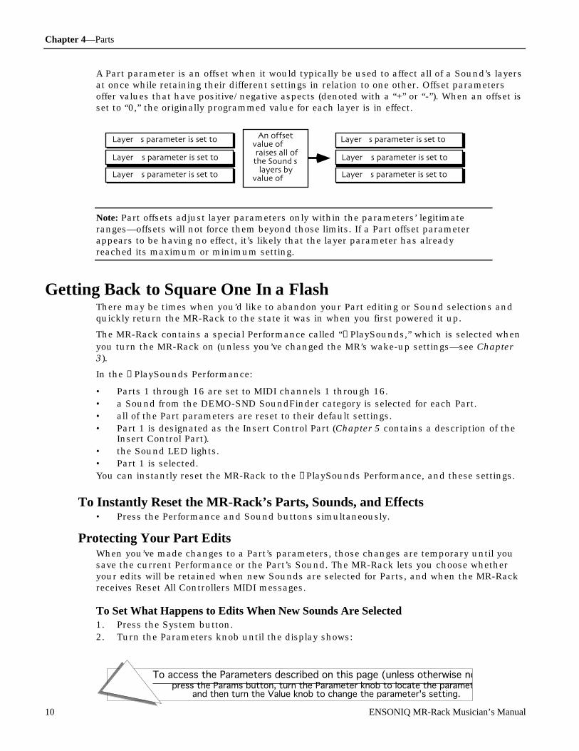
Chapter 4—Parts
To access the Parameters described on this page (unless otherwise noted):press the Params button, turn the Parameter knob to locate the parameter,
and then turn the Value knob to change the parameter's setting.
10 ENSONIQ MR-Rack Musician’s Manual
A Part parameter is an offset when it would typically be used to affect all of a Sound’s layersat once while retaining their different settings in relation to one other. Offset parametersoffer values that have positive/negative aspects (denoted with a “+” or “-”). When an offset isset to “0,” the originally programmed value for each layer is in effect.
Layer 1's parameter is set to 96
Layer 2's parameter is set to 27
Layer 3's parameter is set to 44
Layer 1's parameter is set to 106
Layer 2's parameter is set to 37
Layer 3's parameter is set to 54
An offsetvalue of +10 raises all ofthe Sound's
layers byvalue of +10
Note: Part offsets adjust layer parameters only within the parameters’ legitimateranges—offsets will not force them beyond those limits. If a Part offset parameterappears to be having no effect, it’s likely that the layer parameter has alreadyreached its maximum or minimum setting.
Ge t t ing Bac k to S quar e One In a FlashThere may be times when you’d like to abandon your Part editing or Sound selections andquickly return the MR-Rack to the state it was in when you first powered it up.
The MR-Rack contains a special Performance called “→PlaySounds,” which is selected whenyou turn the MR-Rack on (unless you’ve changed the MR’s wake-up settings—see Chapter3).
In the →PlaySounds Performance:
• Parts 1 through 16 are set to MIDI channels 1 through 16.• a Sound from the DEMO-SND SoundFinder category is selected for each Part.• all of the Part parameters are reset to their default settings.• Part 1 is designated as the Insert Control Part (Chapter 5 contains a description of the
Insert Control Part).• the Sound LED lights.• Part 1 is selected.You can instantly reset the MR-Rack to the →PlaySounds Performance, and these settings.
To Instantly Reset the MR-Rack’s Parts, Sounds, and Effects• Press the Performance and Sound buttons simultaneously.
Protecting Your Part EditsWhen you’ve made changes to a Part’s parameters, those changes are temporary until yousave the current Performance or the Part’s Sound. The MR-Rack lets you choose whetheryour edits will be retained when new Sounds are selected for Parts, and when the MR-Rackreceives Reset All Controllers MIDI messages.
To Set What Happens to Edits When New Sounds Are Selected1. Press the System button.2. Turn the Parameters knob until the display shows:

Chapter 4—Parts
To access the Parameters described on this page (unless otherwise noted):press the Params button, turn the Parameter knob to locate the parameter,
and then turn the Value knob to change the parameter's setting.
ENSONIQ MR-Rack Musician’s Manual 11
System parameters:Part Param Reset= On
iThis may say “Off”
3. Set the Part Param Reset parameter’s value to suit your needs:• If you’d prefer Part parameters to be reset for each new Sound selected for a Part,
set Part Param Reset to On.• If you’d prefer for the current Part parameter settings to remain intact when a new
Sound is selected for that Part, set to Part Param Reset to Off.
To Set the MR’s Response to Reset All Controllers Messages1. Press System.2. Turn the Parameter knob until the display shows “ResetControlRecv=.”
The ResetControlRecv parameter can be set to:• Off—the MR-Rack will ignore Reset All Controllers MIDI messages• On—any Part receiving a Reset All Controllers message on its MIDI channel will
reset its real-time controllers and any parameters that respond to MIDI controllersto default values
3. Turn the Value knob to set ResetControlRecv to Off if you want to protect changesyou’ve made to Part parameters, or to On if you prefer Reset All Controllers messages toreset the Part parameters described above.
M ut ing and Soloing Par t s
Performance System Effects
Sound Params Mute
Part
Bypass
The Mute button serves three functions:• It can mute a Part.• It can solo a single Part.• It can group solo multiple Parts.
About the Mute LEDThe Mute LED informs you of the mute/solo status of any Part you select:• The Mute LED turns off if the selected Part is not muted.• The Mute LED lights solidly if the selected Part is muted.• The Mute LED flashes if the selected Part is soloed (single or group solo).

Chapter 4—Parts
To access the Parameters described on this page (unless otherwise noted):press the Params button, turn the Parameter knob to locate the parameter,
and then turn the Value knob to change the parameter's setting.
12 ENSONIQ MR-Rack Musician’s Manual
MuteThe mute function can be used to silence individual Parts. This can be handy as atemporary measure when you’re refining your set-up. In addition, Performances rememberwhich Parts are muted—when you save a Performance, the mute status of each Part is savedas well—so you can also make your mutes a permanent feature of any given Performance.
It’s worth noting that, even though muting turns off a Part’s Sound, MIDI controllers are stillreceived by the Part. This allows the silenced Part to continue to control the Insert Effect ifit’s designated as a Performance’s Insert Control Part (see Chapter 5 for more information onInsert Effects).
The setting of the Part Param Reset System parameter (see "Protecting Your Part Edits"above) will determine whether or not the Part will automatically un-mute when you select anew Sound for it. If Part Param Reset=On, the Part will be un-muted when you pick a newSound; if it’s set to Off, the Part will remain muted until you un-mute it with the Mutebutton.
To Mute a Part1. Make sure the Part you want to mute is selected. If it’s not, use the Select Part buttons
to select it.2. Press the Mute button once—its LED will light.
This parameter also responds to an NRPN LSB value of 36. See “Using RPNs and NRPNs toEdit Part Parameters” at the end of this chapter.
To Un-Mute a Part1. Make sure the Part you want to un-mute is selected. If it’s not, use the Select Part
buttons to select it.2. Press the Mute button once—its LED will turn off.
This parameter also responds to an NRPN LSB value of 36. See “Using RPNs and NRPNs toEdit Part Parameters” at the end of this chapter.
SoloThe Mute button can also be used for soloing Parts. When a Part is soloed, all the otherParts in a Performance are silenced. Soloing allows you to isolate an individual Part when anumber of them are currently responding to incoming MIDI. If more than one Part isresponding to the same MIDI channel—as when you’re using a Stak—soloing lets you listento a single Part all by itself. If you’re using a sequencer, soloing provides a way to quicklyturn off all of the Parts so that you can listen to one Part alone.
The MR-Rack’s solo feature is exceptionally smart—when you solo a Part, the MR-Rackremembers the mute/solo status of all the other Parts in the Performance. When you un-solo the soloed Part, all the other Parts will be conveniently returned to their prior state.
Parts can be soloed temporarily as you refine your set-up. In addition, Performancesremember which Parts are soloed—when you save a Performance, the solo status of eachPart is saved as well—so you can also make a soloed Part a permanent feature of any givenPerformance.

Chapter 4—Parts
To access the Parameters described on this page (unless otherwise noted):press the Params button, turn the Parameter knob to locate the parameter,
and then turn the Value knob to change the parameter's setting.
ENSONIQ MR-Rack Musician’s Manual 13
To Solo a Part1. Make sure the Part you want to solo is selected. If it’s not, use the Select Part buttons to
select it.2. Double-click the Mute button—its LED will start to blink on and off.
This parameter also responds to an NRPN LSB value of 36. See “Using RPNs and NRPNs toEdit Part Parameters” at the end of this chapter.
To Un-Solo a Part1. Make sure the Part you want to un-solo is selected. If it’s not, use the Select Part
buttons to select it.2. Press the Mute button once—its LED will turn off.
This parameter also responds to an NRPN LSB value of 36. See “Using RPNs and NRPNs toEdit Part Parameters” at the end of this chapter.
To Learn Whether Other Parts Were Already MutedWhile you’ve got a Part soloed, you can tell whether or not the currently muted Parts hadalready been muted.
1. Select the Part whose prior status interests you, using the Select Part buttons.On the top line of the display, next to the number of the Part you selected, the word“mute” will appear.
m
pt02mute ROM004:000AC-PIANO: Piano
(The rest of the display will vary depending on what you were doing before you soloedyour Part.)• If the “mute” is solidly lit, this Part was not muted before you soloed your Part.• If “mute” is flashing, this Part was muted before you soloed your other Part.
Group SoloThe Mute button can be used to solo multiple Parts, which is referred to as a group solo.When the group of Parts is soloed, all the other Parts in a Performance are silenced. Soloinggroups of Parts allows you to isolate them when other Parts responding to MIDI are makingthem hard to hear. Group soloing would allow you to listen only to particular components ina Stak, or selected elements of a Performance when using an external sequencer.
The MR-Rack’s solo feature is exceptionally smart—when you solo Parts, the MR-Rackremembers the mute/solo status of all the other Parts in the Performance. When you un-solo the soloed Parts, all the other Parts will be conveniently returned to their prior state.
Parts can be group soloed temporarily as you refine your set-up. In addition, Performancesremember which Parts are soloed—when you save a Performance, the solo status of eachPart is saved as well—so you can also make a group of soloed Parts a permanent feature ofany given Performance.
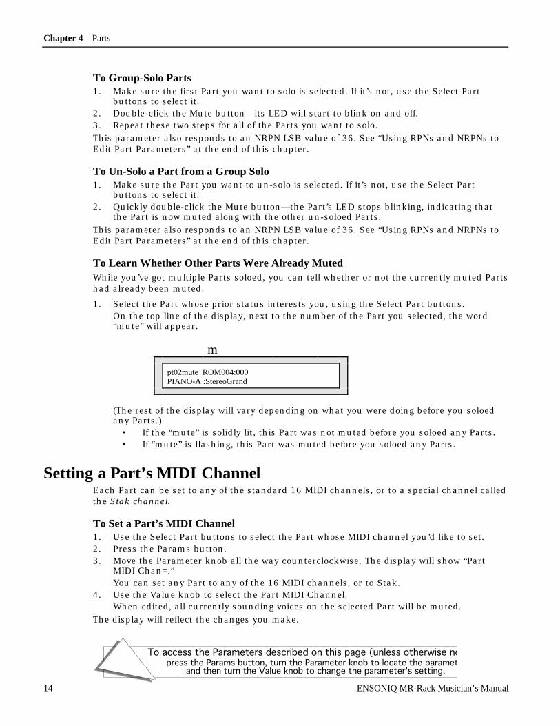
Chapter 4—Parts
To access the Parameters described on this page (unless otherwise noted):press the Params button, turn the Parameter knob to locate the parameter,
and then turn the Value knob to change the parameter's setting.
14 ENSONIQ MR-Rack Musician’s Manual
To Group-Solo Parts1. Make sure the first Part you want to solo is selected. If it’s not, use the Select Part
buttons to select it.2. Double-click the Mute button—its LED will start to blink on and off.3. Repeat these two steps for all of the Parts you want to solo.
This parameter also responds to an NRPN LSB value of 36. See “Using RPNs and NRPNs toEdit Part Parameters” at the end of this chapter.
To Un-Solo a Part from a Group Solo1. Make sure the Part you want to un-solo is selected. If it’s not, use the Select Part
buttons to select it.2. Quickly double-click the Mute button—the Part’s LED stops blinking, indicating that
the Part is now muted along with the other un-soloed Parts.
This parameter also responds to an NRPN LSB value of 36. See “Using RPNs and NRPNs toEdit Part Parameters” at the end of this chapter.
To Learn Whether Other Parts Were Already MutedWhile you’ve got multiple Parts soloed, you can tell whether or not the currently muted Partshad already been muted.
1. Select the Part whose prior status interests you, using the Select Part buttons.On the top line of the display, next to the number of the Part you selected, the word“mute” will appear.
m
pt02mute ROM004:000PIANO-A :StereoGrand
(The rest of the display will vary depending on what you were doing before you soloedany Parts.)
• If the “mute” is solidly lit, this Part was not muted before you soloed any Parts.• If “mute” is flashing, this Part was muted before you soloed any Parts.
Se t t ing a P ar t ’ s M ID I Channe lEach Part can be set to any of the standard 16 MIDI channels, or to a special channel calledthe Stak channel.
To Set a Part’s MIDI Channel1. Use the Select Part buttons to select the Part whose MIDI channel you’d like to set.2. Press the Params button.3. Move the Parameter knob all the way counterclockwise. The display will show “Part
MIDI Chan=.”You can set any Part to any of the 16 MIDI channels, or to Stak.
4. Use the Value knob to select the Part MIDI Channel.When edited, all currently sounding voices on the selected Part will be muted.
The display will reflect the changes you make.

Chapter 4—Parts
To access the Parameters described on this page (unless otherwise noted):press the Params button, turn the Parameter knob to locate the parameter,
and then turn the Value knob to change the parameter's setting.
ENSONIQ MR-Rack Musician’s Manual 15
The current Part’s MIDI channel
m
Pt01§01 HarpsichordPart MIDI Chan= 01
Tip: When a standard Sound (not a Drum Kit) is assigned to a Part, repeatedlypressing the Params button will toggle between this parameter and the FX Busparameter. If the Part uses a Drum Kit, pressing the Params button will togglebetween the Part MIDI Channel parameter and the DrumKey FX Bus parameter.
U sing St aksThe MR-Rack offers a powerful new device for layering Sounds or creating splits—it’s calleda Stak—and there’s one available in each Performance.
Multi-timbral MIDI modules have traditionally offered the possibility of creating layers andsplits by assigning multiple Sounds to the same MIDI channel. (In the case of splits, theSounds are mapped to respond to different pitch ranges.) Creating layers and splits in thismanner can be awkward, however, since any program changes on the common MIDIchannel will undo your carefully-designed Sound combinations, forcing all of the Sounds tothe same program. In addition, if you decide to change the MIDI channel you want to use forthe layer or split, you have to individually reset the MIDI channel of each Sound involved.While you’re free to use the traditional method with the MR-Rack, Staks offer a more elegantapproach.
In the MR-Rack, you can create layers and splits by assigning Parts—and their Sounds—tothe Stak MIDI channel. This accomplishes four things:
• All of the Parts—and their Sounds—will respond to the same MIDI channel.• By changing a single System parameter you can set the entire group of Parts to respond
to the MIDI channel of your choice.• You can protect your Sound combinations from unintentional alteration.• You can still customize each Part independently without affecting the other Parts in the
Stak.
To Create a Stak1. Press the System button and turn the Parameter knob until the following display
appears:
System parameters:Stak MIDI Channel=01
iThis number may be different on your display
2. Turn the Value knob to select the MIDI channel you want to use to control the Stak.3. Press the Params button.4. Press the up or down Select Part buttons until the number of the first Part you want to

Chapter 4—Parts
To access the Parameters described on this page (unless otherwise noted):press the Params button, turn the Parameter knob to locate the parameter,
and then turn the Value knob to change the parameter's setting.
16 ENSONIQ MR-Rack Musician’s Manual
use in your Stak is displayed in the upper-left-hand corner of the display.5. Turn the Parameters knob until the bottom line of the display shows “Part MIDI
Channel.”
Your top line may look a bit different
m
pt01 §01 HarpsichordPart MIDI Chan= 01
iThis number may be different on your display
6. Turn the Value knob until Part MIDI Channel=Stak.Note that the Part’s MIDI channel on the top line of the display has changed to “stak.”When you’re selecting Sounds for a Part, or editing Part parameters, you can look tothis area to quickly ascertain if the selected Part is assigned to a Stak.
m
pt01stak HarpsichordPart MIDI Chan= Stak
The Part you’re working with will now respond to MIDI on the Stak MIDI channel youchose in Step 2.
7. Press the Sounds button.8. Use the Sound Type knob and the Sound Name knob to select a Sound for the first Part
in your Stak.9. Repeat Steps 3 through 8 to add other Parts—and Sounds—to the Stak.
Each Part in the Stak can be edited, using the Part parameters described in this chapter,without affecting the other Parts in the Stak. You create splits by setting Parts in a Stak todifferent key ranges with the Key Range Lo and Hi parameters, described later in thischapter.
The System parameter Stak Coherence allows you to perfectly synchronize the beginning ofany notes played in a Stak. Details on this parameter can be found in Chapter 3 .
Tip: If you’d like to enjoy the layers or splits in any of the MR-Rack’s ROMPerformances, Steps 1 and 2 above will allow you to access them on any MIDIchannel that’s convenient for you.

Chapter 4—Parts
To access the Parameters described on this page (unless otherwise noted):press the Params button, turn the Parameter knob to locate the parameter,
and then turn the Value knob to change the parameter's setting.
ENSONIQ MR-Rack Musician’s Manual 17
C ont r olling a P ar t ’ s Lou dne ssThe loudness for each Part can be set manually from the MR-Rack’s front panel or via MIDIVolume or Expression control messages. The Volume amount determines the maximumloudness of a Part’s Sound. Expression can raise or lower the Part’s level, but only up to themaximum set by Volume.
Volume setting127
0
Mix (Expression)
This allows you to set an acceptable loudness ceiling for a Part, and to adjust its levelwithout worrying that it will ever become too loud. It’s also possible to invert the Part’sresponse to Volume and Expression messages, so that greater values lower the Part’svolume, and vice versa. This can be useful, for instance, when you’d like a Part to fade in asa result of MIDI Volume or Expression messages, while another Part fades out from the verysame messages.
To Set a Part’s Maximum VolumeThe Part Volume parameter allows you to override the loudness level programmed into theSound currently installed on the Part you’re editing. A Volume setting of 100 will leave theSound’s level set as programmed. Lower values will reduce the Sound’s loudness—down by96dB at a value of 0—and values above 100 will make it louder than programmed.
1. Use the Select Part buttons to choose the Part whose volume ceiling you’d like to set.2. Press the Params button.3. Turn the Parameter knob until the display shows “Part Volume=.”4. Turn the Value knob from 0 to 127 to adjust the part’s Volume, or transmit MIDI
Controller #7 values to the MR-Rack. See “To Enable or Disable a Part’s Reception ofPitch Bend Messages” later in this chapter.The MR-Rack’s display will reflect Volume changes made via MIDI just as if you’d madethem from the front panel.
When this parameter is edited on a Part that uses a Drum Kit, all of the Sounds in theDrum Kit are affected simultaneously by the changes you make.
To Adjust the Relative Loudness of a Part1. Use the Select Part buttons to choose the Part whose relative loudness you’d like to
adjust.2. Press the Params button.3. Turn the Parameter knob until the display shows “Expression (Mix)=.”
The Part Expression parameter allows you to mix the level of the Sound currentlyinstalled on the Part you’re editing, up to the maximum set by the Part Volumeparameter above. A setting of 000 will reduce the Part’s loudness -96dB below the levelset with the Part Volume parameter.
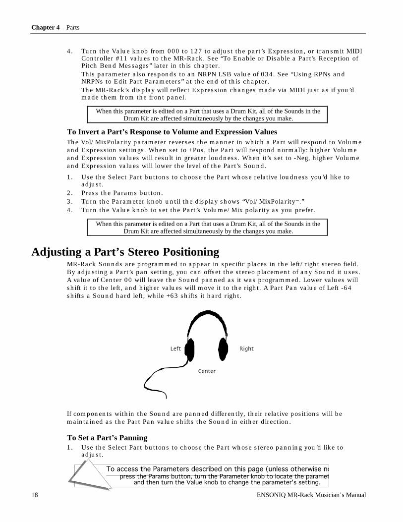
Chapter 4—Parts
To access the Parameters described on this page (unless otherwise noted):press the Params button, turn the Parameter knob to locate the parameter,
and then turn the Value knob to change the parameter's setting.
18 ENSONIQ MR-Rack Musician’s Manual
4. Turn the Value knob from 000 to 127 to adjust the part’s Expression, or transmit MIDIController #11 values to the MR-Rack. See “To Enable or Disable a Part’s Reception ofPitch Bend Messages” later in this chapter.This parameter also responds to an NRPN LSB value of 034. See “Using RPNs andNRPNs to Edit Part Parameters” at the end of this chapter.The MR-Rack’s display will reflect Expression changes made via MIDI just as if you’dmade them from the front panel.
When this parameter is edited on a Part that uses a Drum Kit, all of the Sounds in theDrum Kit are affected simultaneously by the changes you make.
To Invert a Part’s Response to Volume and Expression ValuesThe Vol/MixPolarity parameter reverses the manner in which a Part will respond to Volumeand Expression settings. When set to +Pos, the Part will respond normally: higher Volumeand Expression values will result in greater loudness. When it’s set to -Neg, higher Volumeand Expression values will lower the level of the Part’s Sound.
1. Use the Select Part buttons to choose the Part whose relative loudness you’d like toadjust.
2. Press the Params button.3. Turn the Parameter knob until the display shows “Vol/MixPolarity=.”4. Turn the Value knob to set the Part’s Volume/Mix polarity as you prefer.
When this parameter is edited on a Part that uses a Drum Kit, all of the Sounds in theDrum Kit are affected simultaneously by the changes you make.
A dj ust ing a P ar t ’ s St er e o Posit ioningMR-Rack Sounds are programmed to appear in specific places in the left/right stereo field.By adjusting a Part’s pan setting, you can offset the stereo placement of any Sound it uses.A value of Center 00 will leave the Sound panned as it was programmed. Lower values willshift it to the left, and higher values will move it to the right. A Part Pan value of Left -64shifts a Sound hard left, while +63 shifts it hard right.
64 Left 63 Right
00Center
If components within the Sound are panned differently, their relative positions will bemaintained as the Part Pan value shifts the Sound in either direction.
To Set a Part’s Panning1. Use the Select Part buttons to choose the Part whose stereo panning you’d like to
adjust.

Chapter 4—Parts
To access the Parameters described on this page (unless otherwise noted):press the Params button, turn the Parameter knob to locate the parameter,
and then turn the Value knob to change the parameter's setting.
ENSONIQ MR-Rack Musician’s Manual 19
2. Press the Params button.3. Turn the Parameter knob until the display shows “Pan=.”
The Pan Part parameter can be set from -64 (hard left) to +63 (hard right).4. Turn the Value knob to select a location within the stereo field for the part, or transmit
MIDI Controller #10 values to the MR-Rack.The MR-Rack’s display will reflect Part Pan changes made via MIDI just as if you’d madethem from the front panel.
When this parameter is edited on a Part that uses a Drum Kit, all of the Sounds in theDrum Kit are affected simultaneously by the changes you make.
A dding Ef f e c ts t o P ar t SoundsEvery MR-Rack Performance contains three Effects:
• a stereo Insert Effect• a stereo Global Chorus• a stereo Global Reverb
You’ll find a detailed description of the MR-Rack Effects in Chapter 5.
Parts may be routed to any of these Effects, or left dry. To send a Part’s Sound to an Effect,the Part must be assigned to an Effect bus. There are six possible busses, named for theEffect they access. You can select:
• Insert—to send a Part to the Performance’s Insert Effect.• Chorus—to send a Part through the Global Chorus.• LightReverb—to add a minimal amount of Global Reverb to a Part’s Sound.• MediumReverb—to add a greater amount of Global Reverb to a Part’s Sound.• WetReverb—to add a large amount of Global Reverb to a Part’s Sound.• Dry—for Parts that you don’t want to send through any of the Effects.
Tip: When a standard Sound (not a Drum Kit) is assigned to a Part, repeatedlypressing the Params button will toggle between this parameter and the Part MIDIChannel parameter.
The following parameter is not present when the Part being edited uses a Drum Kit.
To Route a Part to an Effect1. Use the Select Part buttons to choose the Part you’d like to route to an Effect.2. Press the Params button.3. Turn the Parameter knob until the display shows “FX Bus=.”4. Use the Value knob to select Insert, Chorus, LightReverb, MediumReverb, WetReverb, or
Dry.
Routing a Non-Insert Control Part to an FX Bus via MIDIPart that are not designated as the Insert Control Part can be assigned to the Chorus bus,one of the Reverb busses or the Dry bus via MIDI. If such a Part receives MIDI controller 93with a value of 1 or higher, it will be assigned to the Chorus FX bus. If the Part receivesMIDI controller 93 with a zero value, it will be assigned to one of the Reverb busses or theDry bus, according to the following scheme:
• If the Part receives a Controller 91 value of 0, it will be assigned to the Dry bus.
Chapter 4—Parts
To access the Parameters described on this page (unless otherwise noted):press the Params button, turn the Parameter knob to locate the parameter,
and then turn the Value knob to change the parameter's setting.
20 ENSONIQ MR-Rack Musician’s Manual
• If the Part receives a Controller 91 value of 1-40, it will be assigned to the LightReverbbus.
• If the Part receives a Controller 91 value of 41-80, it will be assigned to theMediumReverb bus.
• If the Part receives a Controller 91 value of 81-127, it will be assigned to the WetReverbbus.
Tip: See “Using the Insert Control Part to Pick Insert Effects Via MIDI” in Chapter 5to learn how to select Insert Effects via MIDI.
C ont r olling a P ar t ’ s P it c h Be nd R e spon se A Pitch-Bend Wheel is a spring-loaded wheel typically located to the far left of a MIDIkeyboard. It’s most commonly used to bend the pitch of notes up or down by pushing thewheel forward (up) or pulling it back (down). Some manufacturers employ a left/rightscheme.
The MR-Rack offers two parameters—Pitch Bend Up and Pitch Bend Down—that allow youto separately set how you want each Part to respond to MIDI Pitch Bend messages receivedfrom a Pitch Bend Wheel pushed in either direction.
These parameters will have no effect if the Pitch Bend Recv parameter is set to Off. See “ToEnable or Disable a Part’s Reception of Pitch Bend Messages” later in this chapter.
The following parameter is not present when the Part being edited uses a Drum Kit.
To Set the Part’s Response To a Pitch Bend Wheel Pushed Forward1. Use the Select Part buttons to choose the Part whose Pitch Bend you’d like to
customize.2. Press the Params button.3. Turn the Parameter knob until the display shows “Pitch Bend Up=.”
Pitch Bend Up can be set to:• 1-12dn or 1-12up—to lower or raise the pitch of the Part’s Sound by 1 to 12 equal-
temper semitones when a Pitch Bend Wheel is pushed all the way forward• Prog—to respond to upward Pitch Bend movements according to the value
programmed into the Sound• Sys—to use the global System Pitch Bend Up value (see Chapter 3 for details)• Off—to ignore MIDI messages received from a Pitch Bend Wheel pushed forward
4. Turn the Value knob to select the Pitch Bend Up value you prefer.
This parameter also responds to an RPN LSB value of 000 and an NRPN LSB value of 022.See “Using RPNs and NRPNs to Edit Part Parameters” at the end of this chapter.
The following parameter is not present when the Part being edited uses a Drum Kit.
To Set the Part’s Response To a Pitch Bend Wheel Pulled Back1. Use the Select Part buttons to choose the Part whose Pitch Bend you’d like to
customize.2. Press the Params button.3. Turn the Parameter knob until the display shows “Pitch Bend Down=.”
Pitch Bend Down can be set to:

Chapter 4—Parts
To access the Parameters described on this page (unless otherwise noted):press the Params button, turn the Parameter knob to locate the parameter,
and then turn the Value knob to change the parameter's setting.
ENSONIQ MR-Rack Musician’s Manual 21
• 1-12dn or 1-12up—to lower or raise the pitch of the Part’s Sound by 1 to 12 equal-temper semitones when a Pitch Bend Wheel is pulled all the way back
• Prog—to respond to downward Pitch Bend movements according to the valueprogrammed into the Sound
• Sys—to use the global System Pitch Bend Down value (see Chapter 3 for details)• Off—to ignore MIDI messages received from a Pitch Bend Wheel pulled back
4. Turn the Value knob to select the Pitch Bend Down value you prefer.
This parameter also responds to an RPN LSB value of 000 and an NRPN LSB value of 023.See “Using RPNs and NRPNs to Edit Part Parameters” at the end of this chapter.
Note: When you select a new Sound for the Part, Pitch Bend Up and Pitch Bend Downwill be reset to Prog if the System Part Param Reset parameter is set to On (seeChapter 3 for details).
R e t uning a P ar t On a global level, the MR-Rack’s overall tuning can be adjusted with the System Fine Tuningparameter (see Chapter 3 for details). This parameter retunes all the Parts in the MR-Racksimultaneously. You can also re-tune individual Parts with the Part Octave Shift, SemitoneShift and Fine Tuning parameters.
The following parameter is not present when the Part being edited uses a Drum Kit.
To Re-Tune a Part by Octaves1. Use the Select Part buttons to choose the Part whose octave tuning you’d like to alter.2. Press the Params button.3. Turn the Parameter knob until the display shows “Octave Shift=.”4. Use the Value knob to retune the Part’s Sound in octave steps, if desired.
A setting of 0oct will result in the Part using the octave tuning value programmed intoany Sound it uses. You can shift the Part up or down by a maximum of four equal-temper octaves.
This parameter also responds to an NRPN LSB value of 011. See “Using RPNs and NRPNs toEdit Part Parameters” at the end of this chapter.
The following parameter is not present when the Part being edited uses a Drum Kit.
To Re-Tune a Part by Semitones1. Use the Select Part buttons to choose the Part whose coarse—or semitone—tuning you’d
like to alter.2. Press the Params button.3. Turn the Parameter knob until the display shows “Semitone Shift=.”4. Use the Value knob to set the semitone tuning for the part.
A setting of 0st will result in the Part using the semitone tuning value programmed intoany Sound it uses. You can shift the Part upward by a maximum of 63 keyboard equal-temper semitones or downward by a maximum of 64.
This parameter also responds to an RPN LSB value of 002. See “Using RPNs and NRPNs toEdit Part Parameters” at the end of this chapter.
Chapter 4—Parts
To access the Parameters described on this page (unless otherwise noted):press the Params button, turn the Parameter knob to locate the parameter,
and then turn the Value knob to change the parameter's setting.
22 ENSONIQ MR-Rack Musician’s Manual
The following parameter is not present when the Part being edited uses a Drum Kit.
To Fine-Tune a Part1. Use the Select Part buttons to choose the Part whose fine-tuning you’d like to alter.2. Press the Params button.3. Turn the Parameter knob until the display shows “Fine Tuning=.”4. Use the Value knob to adjust the fine tuning for the Part.
A setting of 0cents will result in the Part using the fine-tuning value programmed intoany Sound it uses. You can lower or raise the Part's fine tuning by -50 to +49 cents.100 cents equals one semitone.
This parameter also responds to an RPN LSB value of 001. See “Using RPNs and NRPNs toEdit Part Parameters” at the end of this chapter.
Note: When you select a new Sound for the Part, all of the Part tuning values will bereset to obey the tuning values programmed into the new Sound if the System PartParam Reset parameter is set to On (see Chapter 3 for details).
U sing Spe c ial P it c h Table sThe MR-Rack provides a number of special pitch tables, as well as a custom pitch tablewhich you can design on your computer with the proper software and transmit via MIDI overto the MR-Rack. "About RAM Pitch Tables" in Chapter 9 provides detailed information oncreating your own pitch tables, and Chapter 3 contains more information on setting theMR-Rack’s system, or global, pitch table. Any Part can be assigned to use one of thesespecial tuning tables.
The following parameter is not present when the Part being edited uses a Drum Kit.
To Assign a Part to a Special Pitch Table1. Use the Select Part buttons to choose the Part whose pitch table you’d like to set.2. Press the Params button.3. Turn the Parameter knob until the display shows “PitchTbl=.”
PitchTbl can be set to:• Prog—to use the PitchTbl value programmed into the Sound• Sys—to use the global System PitchTbl (see Chapter 3 for details)• One of the special pitch tables built in to the MR-Rack’s memoryChapter 9 provides a list of the MR-Rack pitch tables.
4. Turn the Value knob to select the PitchTbl value you prefer.
Note: When you select a new Sound for the Part, PitchTbl will be reset to Prog if theSystem Part Param Reset parameter is set to On (see Chapter 3 for details).
This parameter also responds to an NRPN LSB value of 021. See “Using RPNs and NRPNs toEdit Part Parameters” at the end of this chapter.
D e t e r m ining Whe t he r a P ar t ’ s Sound Will Glide It can be desirable for the notes in a Sound to glide from one to the next as you play them.
Chapter 4—Parts
To access the Parameters described on this page (unless otherwise noted):press the Params button, turn the Parameter knob to locate the parameter,
and then turn the Value knob to change the parameter's setting.
ENSONIQ MR-Rack Musician’s Manual 23
By setting the Part Glide Mode parameter to On, the Sound the Part is using will beendowed with this gliding capability. Some of the MR-Rack’s Sounds are alreadyprogrammed with components that glide between notes—if you’d like, you can disable theglide built into such a Sound by setting its Part’s Glide Mode parameter to Off. If you’d likethe Sound to operate as programmed, you can choose the Prog value for the parameter.
The following parameter is not present when the Part being edited uses a Drum Kit.
To Enable a Part’s Glide Mode From the MR-Rack’s Front Panel1. Use the Select Part buttons to choose the Part whose glide mode you’d like to enable.2. Press the Params button.3. Turn the Parameter knob until the display shows “Glide Mode=.”
You can set the Part Glide Mode to:• Prog—to use the glide characteristics of the Sound used by the Part• Off—to disable the glide characteristics of the Sound used by the Part• On—to enable the Part’s Sound to glide from note to note
4. Turn the Value knob to set the parameter to On.
Note: When you select a new Sound for the Part, Glide Mode will be reset to Prog ifyou’ve changed it by using the MR-Rack’s front-panel controls, and if the SystemPart Param Reset parameter is set to On (see Chapter 3 for details).
The following parameter is not present when the Part being edited uses a Drum Kit.
To Disable a Part’s Glide Mode From the MR-Rack’s Front Panel1. Use the Select Part buttons to choose the Part whose Glide mode you’d like to disable.2. Press the Params button.3. Turn the Parameter knob until the display shows “Glide Mode=.”
You can set the Part Glide Mode to:• Prog—to use the glide characteristics of the Sound used by the Part• Off—to disable the glide characteristics of the Sound used by the Part• On—to enable the Part’s Sound to glide from note to note
4. Turn the Value knob to set the parameter to Off.
Note: When you select a new Sound for the Part, Glide Mode will be reset to Prog ifyou’ve changed it by using the MR-Rack’s front-panel controls, and if the SystemPart Param Reset parameter is set to On (see Chapter 3 for details).
The MR-Rack also supports the use of MIDI controller 65 as a switch for turning a Part’sglide—or portamento—on and off (with no Prog option). Some MIDI control devices allow youto accomplish this with a foot switch. Since the MR-Rack’s Glide Mode parameter has threeoptions—Prog, On and Off—and MIDI controller 65 supports only two settings (a simple Onand Off switch), Glide Mode in the MR-Rack is a bit more complex than other Partparameters. The two-way MIDI controller 65 is supported behind the scenes, while thethree-way MR-Rack control is accessible through the Glide Mode parameter and display.The two methods for turning Glide Mode on and off overlap in function, and therefore, aparticular methodology is required when using controller 65 to switch glide on and off.
Chapter 4—Parts
To access the Parameters described on this page (unless otherwise noted):press the Params button, turn the Parameter knob to locate the parameter,
and then turn the Value knob to change the parameter's setting.
24 ENSONIQ MR-Rack Musician’s Manual
The following parameter is not present when the Part being edited uses a Drum Kit.
To Enable or Disable a Part’s Glide Mode via MIDI1. Use the Select Part buttons to choose the Part whose Glide mode you’d like to enable or
disable.2. Press the Params button.3. Turn the Parameter knob until the display shows “Glide Mode=.”4. Using the Value knob, set Glide Mode to Off.
If either the hidden two-way controller 65 switch or the visible three-way parameter areset to On, Glide Mode will remain On. By setting the visible three-way parameter to Off,you allow the Part to respond to MIDI controller 65 without any unintended interferencefrom the visible parameter.
5. Send a MIDI controller 65 value of 64 or higher to turn Glide Mode on.At this point, Glide Mode will be enabled, even though the display remains unchanged(it still shows “Off”).
6. To turn Glide Mode off, send a MIDI controller 65 value of 63 or lower.If you’ve enabled glide via MIDI, the MR-Rack’s Value knob will have no effect on theGlide Mode setting until the two-way controller 65 switch has been set to Off via MIDI,following the same logic discussed above in Step 4—neither switch can be on if you’dlike to turn Glide Mode off, or to Prog.This parameter also responds to an NRPN LSB value of 031. See “Using RPNs andNRPNs to Edit Part Parameters” at the end of this chapter.
Note: When you select a new Sound for the Part, Glide Mode will be reset to Prog ifneither the visible three-way parameter or hidden two-way switch are set to On, andif the System Part Param Reset parameter is also set to On (see Chapter 3 for details).
Setting a Part’s Glide TimeWhen a Sound in the MR-Rack is set to glide—as a result of its original programming or thePart Glide Mode parameter—you can adjust the speed at which its notes will glide from oneto the next. This is accomplished by adjusting the Glide Time of the Part that uses theSound. A Glide Time of 0 means that the Sound will glide at its programmed speed. If theSound is gliding only as a result of the Part Glide Mode parameter, it probably has no glidetime programmed into it at all, and therefore won’t glide with a Glide Time setting of 0.Higher Glide Time values speed up the Sound’s glide; lower values slow it down. Themaximum Glide Time setting is +63, the minimum is -64.

Chapter 4—Parts
To access the Parameters described on this page (unless otherwise noted):press the Params button, turn the Parameter knob to locate the parameter,
and then turn the Value knob to change the parameter's setting.
ENSONIQ MR-Rack Musician’s Manual 25
The following parameter is not present when the Part being edited uses a Drum Kit.
To Set a Part’s Glide Time1. Use the Select Part buttons to choose the Part whose Glide Time you’d like to adjust.2. Press the Params button.3. Turn the Parameter knob until the display shows “Glide Time=.”4. Turn the Value knob to adjust the Part’s Glide Time.
This parameter also responds to MIDI controller 5 or an NRPN LSB value of 032. See “UsingRPNs and NRPNs to Edit Part Parameters” at the end of this chapter.
Note: When you select a new Sound for the Part, Glide Time will be reset to 0 if theSystem Part Param Reset parameter is set to On (see Chapter 3 for details).
D e laying Par t SoundsYou can use the Part Delay Offset parameter to increase the amount of time it will take for aPart’s Sound to be heard after it receives a MIDI Note On message. If a Sound has a delaytime already programmed into it, the Part Delay Offset can be used to lengthen that delay byup to 2500 milliseconds (ms). If a Sound has no programmed delay time, the Delay Offsetparameter can delay it up to 2500ms. If the Part Delay Offset is set to 0ms, no delay timewill be added to the Sound the Part uses.
The following parameter is not present when the Part being edited uses a Drum Kit.
To Set a Part’s Delay Time1. Use the Select Part buttons to choose the Part whose Sound you’d like to delay.2. Press the Params button.3. Turn the Parameter knob until the display shows “Delay Offset=.”4. Turn the Value knob to select the Delay Offset value you prefer.
This parameter also responds to an NRPN LSB value of 024. See “Using RPNs and NRPNs toEdit Part Parameters” at the end of this chapter.
Note: When you select a new Sound for the Part, the Delay Offset will be reset to 0msif the System Part Param Reset parameter is set to On (see Chapter 3 for details).
C ust om iz ing Part LF OsLFOs—Low Frequency Oscillators—and noise generators are two important programmingdevices used in the creation of MR-Rack Sounds. They’re both rhythm-oriented soundmodulators. Some of the LFOs and noise generators in MR-Rack Sounds are programmed tobe synchronized (or “sync’d”) to the MR-Rack’s internal clock (see Chapter 3 for moreinformation on using the system clock). By setting the SyncLFO&Noise Part parameter toNormal, you can convert a Sound’s sync’d LFOs and Noise to the normal, unsynchronizedvariety. You can also use this parameter to alter the relationship of a Sound’s sync’d LFOsand Noise to the system clock by setting them to a division of the tempo produced by thesystem clock, from 1/1 to 1/32, including triplets.

Chapter 4—Parts
To access the Parameters described on this page (unless otherwise noted):press the Params button, turn the Parameter knob to locate the parameter,
and then turn the Value knob to change the parameter's setting.
26 ENSONIQ MR-Rack Musician’s Manual
You can adjust a Part Sound’s normal LFO rates with the Normal LFO Rate parameter, andthe depth and delay time for all of its LFOs with the LFO Depth and LFO Delay Time Partparameters.
The following parameter is not present when the Part being edited uses a Drum Kit.
To Convert Sync’d LFOs and Noise to Normal LFOs and Noise1. Use the Select Part buttons to choose the Part whose System-sync’d LFOs and Noise
you’d like to convert.2. Press the Params button.3. Turn the Parameter knob until the display shows “SyncLFO&Noise=.”
The SyncLFO&Noise parameter can be set to:• Prog—to leave the sync’d LFOs and Noise as they’re programmed into the Part’s
Sound.• Normal—to convert the sync’d LFOs and Noise to unsync’d LFOs and Noise.• 1/1 to 1/32T—to set the rhythmic relationship of the sync’d LFOs and Noise to the
system clock’s tempo—a "T" following a number signifies a triplet value.4. Turn the Value knob to set the SyncLFO&Noise parameter to Normal.
This parameter also responds to an NRPN LSB value of 25. See “Using RPNs and NRPNs toEdit Part Parameters” at the end of this chapter.
Note: When you select a new Sound for the Part, SyncLFO&Noise will be reset to Progif the System Part Param Reset parameter is set to On (see Chapter 3 for details).
The following parameter is not present when the Part being edited uses a Drum Kit.
To Set the Relationship of Sync’d LFOs and Noise to the System Clock1. Use the Select Part buttons to choose the Part whose Sound contains the System-sync’d
LFOs and Noise you’d like to re-time.2. Press the Params button.3. Turn the Parameter knob until the display shows “SyncLFO&Noise=.”
The SyncLFO&Noise parameter can be set to:• Prog—to leave the sync’d LFOs and Noise as they’re programmed into the Part’s
Sound.• Normal—to convert the sync’d LFOs and Noise to unsync’d LFOs and Noise.• 1/1 to 1/32T—to set the rhythmic relationship of the sync’d LFOs and Noise to the
system clock’s tempo—a "T" following a number signifies a triplet value.4. Turn the Value knob to set the SyncLFO&Noise parameter to the desired fractional
value to the system clock.
This parameter also responds to an NRPN LSB value of 25. See “Using RPNs and NRPNs toEdit Part Parameters” at the end of this chapter.
Note: When you select a new Sound for the Part, SyncLFO&Noise will be reset to Progif the System Part Param Reset parameter is set to On (see Chapter 3 for details).
The following parameter is not present when the Part being edited uses a Drum Kit.
To Change a Part Sound’s Normal (Unsynchronized) LFO Rates

Chapter 4—Parts
To access the Parameters described on this page (unless otherwise noted):press the Params button, turn the Parameter knob to locate the parameter,
and then turn the Value knob to change the parameter's setting.
ENSONIQ MR-Rack Musician’s Manual 27
1. Use the Select Part buttons to choose the Part whose Sound contains the Normal LFOsyou’d like to re-time.
2. Press the Params button.3. Turn the Parameter knob until the display shows “Normal LFO Rates=.”
The Normal LFO Rates parameter can be set anywhere from -64 to +63 to subtract fromor add to the Part Sound’s programmed LFO rates. A value of 0 will leave the PartSound’s normal LFOs at their programmed rate.
4. Turn the Value knob to set the Normal LFO Rates parameter to the desired rate offset.
This parameter also responds to MIDI controller 75 or an NRPN LSB value of 008. See“Using RPNs and NRPNs to Edit Part Parameters” at the end of this chapter.
The following parameter is not present when the Part being edited uses a Drum Kit.
To Set a Part Sound’s LFO Depth1. Use the Select Part buttons to choose the Part containing the LFOs whose depth you’d
like to adjust.2. Press the Params button.3. Turn the Parameter knob until the display shows “LFO Depth=.”
The LFO Depth parameter can be set to -64 to +63 to subtract from or add to the PartSound’s programmed LFO depth. A value of 0 will leave the Part Sound’s LFOs at theirprogrammed depth.
4. Turn the Value knob to set the LFO Depth parameter to the desired depth offset.
This parameter also responds to an NRPN LSB value of 009. See “Using RPNs and NRPNs toEdit Part Parameters” at the end of this chapter.
Note: When you select a new Sound for the Part, LFO Depth will be reset to 0 if theSystem Part Param Reset parameter is set to On (see Chapter 3 for details).
The following parameter is not present when the Part being edited uses a Drum Kit.
To Set a Part’s LFO Delay1. Use the Select Part buttons to choose the Part containing the LFOs whose delay time
you’d like to adjust.2. Press the Params button.3. Turn the Parameter knob until the display shows “LFO Delay Time=.”4. Turn the Value knob to set the Delay Time offset to the desired amount.
The LFO Delay parameter can be set to -64 to +63 to subtract from or add to the PartSound’s programmed LFO delay time. A value of 0 will leave the Part Sound’s LFOs attheir programmed delay setting.
This parameter also responds to an NRPN LSB value of 010. See “Using RPNs and NRPNs toEdit Part Parameters” at the end of this chapter.
Note: When you select a new Sound for the Part, LFO Delay will be reset to 0 if theSystem Part Param Reset parameter is set to On (see Chapter 3 for details).
C ont r olling the Shape of P ar t S oundsMost of the Sounds in the MR-Rack use envelopes to shape the volume and frequency
Chapter 4—Parts
To access the Parameters described on this page (unless otherwise noted):press the Params button, turn the Parameter knob to locate the parameter,
and then turn the Value knob to change the parameter's setting.
28 ENSONIQ MR-Rack Musician’s Manual
content of their components. The MR-Rack provides a number of Part parameters that allowyou to adjust these envelopes to suit your needs. These parameters subtract from or add tothe programmed values of the envelopes programmed into a Part’s Sound. This preservesthe relationship between all the various envelopes that may exist in a Sound while stillgiving you a great degree of control over the Sound’s volume and timbral contours. The Partparameters which refer to volume, or amplitude, shaping are Amp Env Attack, Amp EnvDecay, and Amp Env Release. The parameters which affect the filtering of the Sound’sfrequency content are Filter Cutoff—which allows you to adjust its filter cutoff settings—FiltEnv Attack, Filt Env Decay, and Filt Env Release. Many envelopes in the MR-Rack’s Soundsrespond to MIDI Velocity. The Amp&Filt Env Vel Part parameter allows you to subtract fromor add to the velocity sensitivity programmed into the amplitude and filter envelopes of aPart’s Sound.
The following parameter is not present when the Part being edited uses a Drum Kit.
To Adjust the Attack Time of Notes in a Part1. Use the Select Part buttons to choose the Part containing the Sound whose amplitude
attack time you’d like to adjust.2. Press the Params button.3. Turn the Parameter knob until the display shows “Amp Env Attack=.”
The Amp Env Attack parameter can be set anywhere from -64 to +63 to subtract fromor add to the Part Sound’s programmed attack times. A value of 0 will leave the PartSound’s various attack times at their programmed settings.
4. Turn the Value knob to set the Amp Env Attack offset to the desired amount.
This parameter also responds to MIDI controller 73 or an NRPN LSB value of 014. See“Using RPNs and NRPNs to Edit Part Parameters” at the end of this chapter.
Note: When you select a new Sound for the Part, Amp Env Attack will be reset to 0 ifthe System Part Param Reset parameter is set to On (see Chapter 3 for details).
The following parameter is not present when the Part being edited uses a Drum Kit.
To Adjust the Decay of Notes in a Part1. Use the Select Part buttons to choose the Part containing the Sound whose amplitude
decay time you’d like to adjust.2. Press the Params button.3. Turn the Parameter knob until the display shows “Amp Env Decay=.”
The Amp Env Decay parameter can be set anywhere from -64 to +63 to subtract from oradd to the Part Sound’s programmed decay times. A value of 0 will leave the PartSound’s various decay times at their programmed settings.
4. Turn the Value knob to set the Amp Env Decay offset to the desired amount.
This parameter also responds to MIDI controller 76 or an NRPN LSB value of 015. See“Using RPNs and NRPNs to Edit Part Parameters” at the end of this chapter.

Chapter 4—Parts
To access the Parameters described on this page (unless otherwise noted):press the Params button, turn the Parameter knob to locate the parameter,
and then turn the Value knob to change the parameter's setting.
ENSONIQ MR-Rack Musician’s Manual 29
Note: When you select a new Sound for the Part, Amp Env Decay will be reset to 0 ifthe System Part Param Reset parameter is set to On (see Chapter 3 for details).
The following parameter is not present when the Part being edited uses a Drum Kit.
To Adjust the Release of Notes in a Part1. Use the Select Part buttons to choose the Part containing the Sound whose amplitude
release time you’d like to adjust.2. Press the Params button.3. Turn the Parameter knob until the display shows “Amp Env Release=.”
The Amp Env Release parameter can be set anywhere from -64 to +63 to subtract fromor add to the Part Sound’s programmed release times. A value of 0 will leave the PartSound’s various release times at their programmed settings.
4. Turn the Value knob to set the Amp Env Release offset to the desired amount.
This parameter also responds to MIDI controller 72 or an NRPN LSB value of 016. See“Using RPNs and NRPNs to Edit Part Parameters” at the end of this chapter.
Note: When you select a new Sound for the Part, Amp Env Release will be reset to 0 ifthe System Part Param Reset parameter is set to On (see Chapter 3 for details).
The following parameter is not present when the Part being edited uses a Drum Kit.
To Adjust the Filter Cutoff of a Part1. Use the Select Part buttons to choose the Part containing the Sound whose filter cutoff
you’d like to adjust.2. Press the Params button.3. Turn the Parameter knob until the display shows “Filter Cutoff=.”
The Filter Cutoff parameter can be set anywhere from -64 to +63 to subtract from oradd to the Part Sound’s programmed filter cutoff settings. A value of 0 will leave thePart Sound’s various filter cutoffs at their programmed settings.
4. Turn the Value knob to set the Filter Cutoff offset to the desired amount.
This parameter also responds to MIDI controller 74 or an NRPN LSB value of 012. See“Using RPNs and NRPNs to Edit Part Parameters” at the end of this chapter.
Note: When you select a new Sound for the Part, Filter Cutoff will be reset to 0 if theSystem Part Param Reset parameter is set to On (see Chapter 3 for details).
The following parameter is not present when the Part being edited uses a Drum Kit.
To Adjust the Filter Attack of a Part1. Use the Select Part buttons to choose the Part containing the Sound whose filter attack
time you’d like to adjust.2. Press the Params button.3. Turn the Parameter knob until the display shows “Filt Env Attack=.”
The Filt Env Attack parameter can be set anywhere from -64 to +63 to subtract from oradd to the Part Sound’s programmed filter attack times. A value of 0 will leave the PartSound’s various filter attack times at their programmed settings.
Chapter 4—Parts
To access the Parameters described on this page (unless otherwise noted):press the Params button, turn the Parameter knob to locate the parameter,
and then turn the Value knob to change the parameter's setting.
30 ENSONIQ MR-Rack Musician’s Manual
4. Turn the Value knob to set the Filt Env Attack offset to the desired amount.
This parameter also responds to an NRPN LSB value of 017. See “Using RPNs and NRPNs toEdit Part Parameters” at the end of this chapter.
Note: When you select a new Sound for the Part, Filt Env Attack will be reset to 0 ifthe System Part Param Reset parameter is set to On (see Chapter 3 for details).
The following parameter is not present when the Part being edited uses a Drum Kit.
To Adjust the Filter Decay of a Part1. Use the Select Part buttons to choose the Part containing the Sound whose filter decay
time you’d like to adjust.2. Press the Params button.3. Turn the Parameter knob until the display shows “Filt Env Decay=.”
The Filt Env Decay parameter can be set anywhere from -64 to +63 to subtract from oradd to the Part Sound’s programmed filter decay times. A value of 0 will leave the PartSound’s various filter decay times at their programmed settings.
4. Turn the Value knob to set the Filt Env Decay offset to the desired amount.
This parameter also responds to an NRPN LSB value of 018. See “Using RPNs and NRPNs toEdit Part Parameters” at the end of this chapter.
Note: When you select a new Sound for the Part, Filt Env Decay will be reset to 0 ifthe System Part Param Reset parameter is set to On (see Chapter 3 for details).
The following parameter is not present when the Part being edited uses a Drum Kit.
To Adjust the Filter Release of a Part1. Use the Select Part buttons to choose the Part containing the Sound whose filter release
time you’d like to adjust.2. Press the Params button.3. Turn the Parameter knob until the display shows “Filt Env Release=.”
The Filt Env Release parameter can be set anywhere from -64 to +63 to subtract from oradd to the Part Sound’s programmed filter release times. A value of 0 will leave the PartSound’s various filter release times at their programmed settings.
4. Turn the Value knob to set the Filt Env Release offset to the desired amount.
This parameter also responds to an NRPN LSB value of 019. See “Using RPNs and NRPNs toEdit Part Parameters” at the end of this chapter.
Note: When you select a new Sound for the Part, Filt Env Release will be reset to 0 ifthe System Part Param Reset parameter is set to On (see Chapter 3 for details).

Chapter 4—Parts
To access the Parameters described on this page (unless otherwise noted):press the Params button, turn the Parameter knob to locate the parameter,
and then turn the Value knob to change the parameter's setting.
ENSONIQ MR-Rack Musician’s Manual 31
The following parameter is not present when the Part being edited uses a Drum Kit.
To Adjust Amp and Filter Envelopes’ Velocity Sensitivity1. Use the Select Part buttons to choose the Part containing the amplitude and filter
envelopes whose velocity sensitivity you’d like to adjust.2. Press the Params button.3. Turn the Parameter knob until the display shows “Amp&Filt Env Vel=.”
The Amp&Filt Env Vel parameter can be set anywhere from -64 to +63 to subtract fromor add to the Part Sound’s amplitude and filter envelopes’ velocity sensitivity. A value of0 will leave the envelopes’ sensitivity to MIDI velocity at their programmed settings.
4. Turn the Value knob to set the Amp&Filt Env Vel offset to the desired amount.
This parameter also responds to an NRPN LSB value of 020. See “Using RPNs and NRPNs toEdit Part Parameters” at the end of this chapter.
Note: When you select a new Sound for the Part, Amp&Filt Env Vel will be reset to 0 ifthe System Part Param Reset parameter is set to On (see Chapter 3 for details).
C hanging a P ar t ’ s Ke y R ange Each Part in the MR-Rack can be set to respond to MIDI Note-Ons received from within aspecified region of a MIDI keyboard controller. This allows the creation of splits and layers.You can split the entire 88-note keyboard range into as many as 16 different key zones byassigning up to 16 Parts to separate keyboard ranges (some MIDI keyboards have only 76 or61 keys). In addition, you can set a Part’s key range to overlap another’s, producing“layered” ranges in which you would hear Sounds from more than one Part. A Part’s keyrange is defined by setting its lowest note with the Key Range Lo Part parameter, and itshighest with the Key Range Hi Part parameter.
Note: A Part’s Key Range Lo value should not be set above its Key Range Hi setting,nor should its Key Range Hi value be set below its Key Range Lo setting.
To Set a Part’s Keyboard Range1. Use the Select Part buttons to choose the Part whose keyboard range you’d like to set.2. Press the Params button.3. Turn the Parameter knob until the display shows “Key Range Lo=.”
The low end of a Part’s key range can be any note you desire, from A0 to C84. Turn the Value knob to set the Key Range Lo to the desired note.
Middle C is C4 (some MIDI controller manufacturers refer to Middle C as C3 check yourcontroller’s or sequencer’s manual to see if that’s the case).This parameter also responds to an NRPN LSB value of 026. See “Using RPNs andNRPNs to Edit Part Parameters” at the end of this chapter.
5. Turn the Parameter knob until the display shows “Key Range Hi=.”The high end of a Part’s key range can be any note you desire, from A0 to C8.
6. Turn the Value knob to set the Key Range Hi to the desired note.This parameter also responds to an NRPN LSB value of 027. See “Using RPNs andNRPNs to Edit Part Parameters” at the end of this chapter.If you want to reset the range, simply reselect these parameters and repeat the process.

Chapter 4—Parts
To access the Parameters described on this page (unless otherwise noted):press the Params button, turn the Parameter knob to locate the parameter,
and then turn the Value knob to change the parameter's setting.
32 ENSONIQ MR-Rack Musician’s Manual
When this parameter is edited on a Part that uses a Drum Kit, all of the Sounds in theDrum Kit are affected simultaneously by the changes you make.
To Create a Keyboard Split1. Press the System button.2. Turn the Parameter knob until the display shows “Stak MIDI Channel.”3. Set the Stak MIDI channel to the channel you’d like to use for your split.4. Press the Sound button.5. Use the Select Part buttons to choose the first Part you’d like to use in your split.6. Using the Sound Type knob and the Sound Name knob, locate a Sound you’d like to use
for your first split Part.7. Press the Params button.8. Turn the Parameter knob until the display shows “Part MIDI Chan.”9. Set Part MIDI Chan to Stak.10. Turn the Parameter knob until the display shows “Key Range Lo=.”
The low end of a Part’s key range can be any note you desire, from A0 to C8.Middle C is C4 (some MIDI manufacturers refer to Middle C as C3 check yourcontroller’s or sequencer’s manual to see if that’s the case).
11. Turn the Value knob to set the Key Range Lo to the desired note.This parameter also responds to an NRPN LSB value of 026. See “Using RPNs andNRPNs to Edit Part Parameters” at the end of this chapter.
12. Turn the Parameter knob until the display shows “Key Range Hi=.”The high end of a Part’s key range can be any note you desire, from A0 to C8.
Note: A Part’s Key Range Lo value cannot be set above its Key Range Hi setting, norcan its Key Range Hi value cannot be set below its Key Range Lo setting.
13. Turn the Value knob to set the Key Range Hi to the desired note.This parameter also responds to an NRPN LSB value of 027. See “Using RPNs andNRPNs to Edit Part Parameters” at the end of this chapter.If you want to reset the range, simply reselect these parameters and repeat the process.
14. Repeat steps 4-14 for each Part you’d like to use in your split, setting each Part to aunique keyboard range.Once you’ve set up your split, you’ll probably want to set up the Effects and Effectrouting for your Parts. See Chapter 5 to learn more about Effects.
To Create a Split with Layered Regions1. Press the System button.2. Turn the Parameter knob until the display shows “Stak MIDI Channel.”3. Set the Stak MIDI channel to the channel you’d like to use for your split.4. Press the Sound button.5. Use the Select Part buttons to choose the first Part you’d like to use in your split.6. Using the Sound Type knob and the Sound Name knob, locate a Sound you’d like to use
for your first split Part.7. Press the Params button.8. Turn the Parameter knob until the display shows “Part MIDI Chan.”9. Set Part MIDI Chan to Stak.10. Turn the Parameter knob until the display shows “Key Range Lo=.”
The low end of a Part’s key range can be any note you desire, from A0 to C8.

Chapter 4—Parts
To access the Parameters described on this page (unless otherwise noted):press the Params button, turn the Parameter knob to locate the parameter,
and then turn the Value knob to change the parameter's setting.
ENSONIQ MR-Rack Musician’s Manual 33
Middle C is C4 (some MIDI controller manufacturers refer to Middle C as C3 check yourcontroller’s or sequencer’s manual to see if that’s the case).
11. Turn the Value knob to set the Key range Lo to the desired note.This parameter also responds to an NRPN LSB value of 026. See “Using RPNs andNRPNs to Edit Part Parameters” at the end of this chapter.
12. Turn the Parameter knob until the display shows “Key Range Hi=.”The high end of a Part’s key range can be any note you desire, from A0 to C8.
Note: A Part’s Key Range Lo value cannot be set above its Key Range Hi setting, norcan its Key Range Hi value cannot be set below its Key Range Lo setting.
13. Turn the Value knob to set the Key Range Hi to the desired note.This parameter also responds to an NRPN LSB value of 027. See “Using RPNs andNRPNs to Edit Part Parameters” at the end of this chapter.If you want to reset the range, simply reselect these parameters and repeat the process.
14. Repeat steps 4-14 for each Part you’d like to use in your split. Parts that you’d like tolayer over each other should share portions, or all, of their keyboard ranges. Parts thatare meant to be unlayered should be set to key ranges that are unused by any otherPart.Once you’ve set up your split, you’ll probably want to set up the Effects and Effectrouting for your Parts. See Chapter 5 to learn more about Effects.
Se t t ing Par t Ve loc it y R ange sParts can be programmed so that the Sounds they use are only heard when the Part receivesMIDI Velocity messages within a specified range.
To Set a Part’s Velocity Window1. Use the Select Part buttons to choose the Part whose velocity window you’d like to set.2. Press the Params button.3. Turn the Parameter knob until the display shows “VelocityRange Lo=.”
The low boundary of a Part’s velocity window can range from 0 to 127.4. Turn the Value knob to set the VelocityRange Lo parameter to the desired value.
This parameter also responds to an NRPN LSB value of 028. See “Using RPNs andNRPNs to Edit Part Parameters” at the end of this chapter.
5. Turn the Parameter knob until the display shows “VelocityRange Hi=.”The high boundary of a Part’s velocity window can range from 0 to 127.
6. Turn the Value knob to set the VelocityRange Hi parameter to the desired value.VelocityRangeLo and Hi also respond to an NRPN LSB value of 029. See “Using RPNsand NRPNs to Edit Part Parameters” at the end of this chapter.
When this parameter is edited on a Part that uses a Drum Kit, all of the Sounds in theDrum Kit are affected simultaneously bythe changes you make.
Isolat ing Ve locit y- D e pe nde nt Com pone nt s of SoundsMany of the Sounds in the MR-Rack are designed to respond to MIDI Velocity messages. It’snot uncommon for different components of Sounds to be revealed only when the Partreceives specific MIDI Velocity values. The MR-Rack provides a way to set Parts so you canreliably produce these values and therefore, the Sound components they produce. This letsyou easily extract favorite aspects MR-Rack Sounds that are only heard at specific velocities.
Chapter 4—Parts
To access the Parameters described on this page (unless otherwise noted):press the Params button, turn the Parameter knob to locate the parameter,
and then turn the Value knob to change the parameter's setting.
34 ENSONIQ MR-Rack Musician’s Manual
When the Velocity Mode Part parameter is set to any value other than Normal, Velocitymessages that fall within the Part’s velocity window (see “Setting Part Velocity Ranges”above) are automatically converted to the velocity set with the Velocity Mode parameter.
To Extract Favorite Velocity-Dependent Components of Sounds1. Use the Select Part buttons to choose the Part whose Sound contains component you’d
like to isolate.2. Press the Params button.3. Turn the Parameter knob until the display shows “Velocity Mode=.”
The Velocity Mode parameter can be set to:• Normal—to allow the Part Sound’s velocity response to function normally.• 0 to 127—to convert any Velocity messages received within the Part’s velocity window to
the value selected.4. Turn the Value knob to set the Velocity Mode parameter to the desired velocity value.
This parameter also responds to an NRPN LSB value of 035. See “Using RPNs and NRPNs toEdit Part Parameters” at the end of this chapter.
When this parameter is edited on a Part that uses a Drum Kit, all of the Sounds in theDrum Kit are affected simultaneously bythe changes you make.
Se t t ing a P ar t 's R e spons e To M ID I Pr e ssur e M e ssage sThe MR-Rack supports Key Pressure as a modulator of its Sounds and Effects. A MIDIkeyboard controller produces Key Pressure when a key is physically pressed down after ithas traveled through its normal range of motion. There are two types of Key Pressure:Channel Pressure and Key Pressure (also referred to as PolyKey or Polyphonic Pressure).Channel Pressure simultaneously affects all currently-sounding notes as if they were asingle entity. Key Pressure allows you to affect each note individually by applying pressureto its counterpart key on your keyboard controller.
MR-Rack Parts can be set to respond to both types of Pressure. Set the PressureMode Partparameter to Channel if you’d like the Part’s Sound to respond only to Channel Pressure, orset it to Key if you’d like it to respond only to Key Pressure. If you’re not sure which type ofPressure you’d like to use, you can set the parameter to Auto—the Part will sense whichtype of Pressure is required, based on what kind of MIDI Pressure data it receives.
To Set a Part’s Pressure Response1. Use the Select Part buttons to choose the Part whose Pressure response you’d like to
set.2. Press the Params button.3. Turn the Parameter knob until the display shows “Pressure Mode=.”
The Pressure Mode parameter can be set to:• Off—so that the Part will not respond to Pressure. If Pressure is assigned as an FX
Mod Source, effects modulation is disabled.• Auto—so that the Part senses the appropriate type of Pressure required based on
the incoming MIDI Pressure data.• Channel—so that the Part will only respond to Channel Pressure.• Key—so that the Part will only respond to Key Pressure.
4. Turn the Value knob to set the Pressure Mode parameter to the desired value.
This parameter also responds to an NRPN LSB value of 030. See “Using RPNs and NRPNs to

Chapter 4—Parts
To access the Parameters described on this page (unless otherwise noted):press the Params button, turn the Parameter knob to locate the parameter,
and then turn the Value knob to change the parameter's setting.
ENSONIQ MR-Rack Musician’s Manual 35
Edit Part Parameters” at the end of this chapter.
Note: When you select a new Sound for the Part, Pressure Mode will be reset to Autoif the System Part Param Reset parameter is set to On (see Chapter 3 for details).
When this parameter is edited on a Part that uses a Drum Kit, all of the Sounds in theDrum Kit are affected simultaneously bythe changes you make.
Wor king wit h P r ogr am C han ges and Bank Se le c t sMIDI allows you to select MR-Rack Sounds remotely from your MIDI controller through thetransmission of Bank Select and Program Change messages. A Bank Select message willspecify the area in the MR-Rack’s memory where a particular Sound resides, and a ProgramChange message will select the Sound itself. Each Part can receive Bank Select and ProgramChange messages on its MIDI channel, or it can be set to ignore either type of message.
When using Program Changes, you can guarantee that the Sound will be selected from theintended bank by sending the appropriate Bank Select message along with, and just priorto, the Program Change. If you’d like, you can select Sounds in the MR-Rack with ProgramChanges that are unaccompanied by Bank Select messages—they’ll simply choose Soundsfrom the currently selected bank. Unaccompanied Bank Select messages may be sent to theMR-Rack to “arm” a Part for a bank change that will occur when the next unaccompaniedProgram Change is received.
To Enable or Disable a Part’s Reception of Program Change Messages1. Use the Select Part buttons to choose the Part whose reception of MIDI Program
Changes you’d like to enable or disable.2. Press the Params button.3. Turn the Parameter knob until the display shows “ProgramChngRecv=.”
The ProgramChngRecv parameter may be set to:• On—to instruct the Part to respond to MIDI Program Change messages• Off—to instruct the Part to ignore MIDI Program Change messages
4. Turn the Value knob to set the ProgramChngRecv parameter value.
Note: BankSelect Recv will have no effect if the global Bank&ProgChgRecv is set toOff. See Chapter 3 for details.
To Enable or Disable a Part’s Reception of Bank Select Messages1. Use the Select Part buttons to choose the Part whose reception of MIDI Bank Selects
you’d like to enable or disable.2. Press the Params button.3. Turn the Parameter knob until the display shows “Bank Select Recv=.”
The Bank Select Recv parameter functions as a combined filter for Bank Select MSBand LSB values. It may be set to:• On—to instruct the Part to respond to MIDI Bank Select messages• Off—to instruct the Part to ignore MIDI Bank Select messages
4. Turn the Value knob to set the Bank Select Recv parameter to the desired value.
Note: This parameter will have no effect if the global Bank&ProgChgRecv is set to Off.

Chapter 4—Parts
To access the Parameters described on this page (unless otherwise noted):press the Params button, turn the Parameter knob to locate the parameter,
and then turn the Value knob to change the parameter's setting.
36 ENSONIQ MR-Rack Musician’s Manual
See Chapter 3 for details.
Finding Out What Bank Select and Program Change Values to SendThe MR-Rack’s display makes it easy to find out which Bank Select and Program Changevalues you’ll need to select the current Sound via MIDI.
How to Select the Current Sound Via MIDI1. Press the Sound button.2. Using the Sound Type and Sound Name knobs, select a Sound.
The display will tell you which Bank Select and Program Change values you’ll need tosend the MR-Rack to select the current Sound from your controller:
The Bank Select value for this Sound The Program Change value for this Sound
l n
pt01 §01 RAM001:033ALL-SND Your Sound
3. Instruct your controller to send the MR-Rack the displayed Bank Select and ProgramChange values.
Enabling and D isabling Par t R e sponse to M ID I Cont r olle r sThe MR-Rack recognizes all of the major MIDI controllers. You can set individual Parts torespond to a each of these controllers, or to ignore it.
To Enable or Disable a Part’s Reception of Data Entry Messages1. Use the Select Part buttons to choose the Part whose reception of MIDI Data Entry
messages you’d like to enable or disable.2. Press the Params button.3. Turn the Parameter knob until the display shows “Data Entry Recv=.”
The Data Entry Recv parameter functions as a combined filter for Data Entry, DataIncrement and Decrement, NRPN MSB 099 and LSB 098, and RPN MSB 101 and LSB100 messages. It may be set to:• On—to instruct the Part to respond the above messages• Off—to instruct the Part to ignore the above messages
4. Turn the Value knob to set the Data Entry Recv parameter to the desired value.
Note: When the Data Entry Recv parameter is edited, Data Entry settings for thecurrently selected Part will be reset to 000 in order to prevent hung Data Entryvalues.
To Enable or Disable a Part’s Reception of Pitch Bend Messages1. Use the Select Part buttons to choose the Part whose reception of MIDI Pitch Bend
messages you’d like to enable or disable.2. Press the Params button.3. Turn the Parameter knob until the display shows “Pitch Bend Recv=.”
The Pitch Bend Recv parameter may be set to:
Chapter 4—Parts
To access the Parameters described on this page (unless otherwise noted):press the Params button, turn the Parameter knob to locate the parameter,
and then turn the Value knob to change the parameter's setting.
ENSONIQ MR-Rack Musician’s Manual 37
• On—to instruct the Part to respond to Pitch Bend messages• Off—to instruct the Part to ignore Pitch Bend messages
4. Turn the Value knob to set the Pitch Bend parameter to the desired value.
Note: When the Pitch Bend parameter is edited, Pitch Bend settings for the currentlyselected Part will be reset to 064 in order to prevent hung Pitch Bend values.
To Enable or Disable a Part’s Reception of Mod Wheel Messages1. Use the Select Part buttons to choose the Part whose reception of MIDI Mod Wheel
(MIDI Controller #1) messages you’d like to enable or disable.2. Press the Params button.3. Turn the Parameter knob until the display shows “Mod Wheel (1) Recv=.”
The Mod Wheel (1) Recv parameter may be set to:• On—to instruct the Part to respond to Mod Wheel messages• Off—to instruct the Part to ignore Mod Wheel messages
4. Turn the Value knob to set the Mod Wheel (1) Recv parameter to the desired value.
Note: When the Mod Wheel (1) Recv parameter is edited, Mod Wheel settings for thecurrently selected Part will be reset to 000 in order to prevent hung Mod Wheelvalues.
To Enable or Disable a Part’s Reception of Foot Pedal Messages1. Use the Select Part buttons to choose the Part whose reception of MIDI Foot Pedal (MIDI
Controller #4) messages you’d like to enable or disable.2. Press the Params button.3. Turn the Parameter knob until the display shows “FootPedal (4) Recv=.”
The FootPedal (4) Recv parameter may be set to:• On—to instruct the Part to respond to Foot Pedal messages• Off—to instruct the Part to ignore Foot Pedal messages
4. Turn the Value knob to set the FootPedal (4) Recv parameter to the desired value.
Note: When the FootPedal (4) Recv parameter is edited, Foot Pedal settings for thecurrently selected Part will be reset 000 in order to prevent hung Foot Pedal values.
To Enable or Disable a Part’s Reception of Volume Messages1. Use the Select Part buttons to choose the Part whose reception of MIDI Volume (MIDI
Controller #7) messages you’d like to enable or disable.2. Press the Params button.3. Turn the Parameter knob until the display shows “Volume(7)Recv=.”
The Volume(7)Recv parameter may be set to:• On—to instruct the Part to respond to Volume messages• Off—to instruct the Part to ignore Volume messages
4. Turn the Value knob to set the Volume(7)Recv parameter to the desired value.
To Enable or Disable a Part’s Reception of Pan Messages1. Use the Select Part buttons to choose the Part whose reception of MIDI Pan (MIDI
Controller #10) messages you’d like to enable or disable.2. Press the Params button.

Chapter 4—Parts
To access the Parameters described on this page (unless otherwise noted):press the Params button, turn the Parameter knob to locate the parameter,
and then turn the Value knob to change the parameter's setting.
38 ENSONIQ MR-Rack Musician’s Manual
3. Turn the Parameter knob until the display shows “Pan(10)Recv=.”The Pan(10)Recv parameter may be set to:• On—to instruct the Part to respond to Pan messages• Off—to instruct the Part to ignore Pan messages
4. Turn the Value knob to set the Pan(10)Recv parameter to the desired value.
To Enable or Disable a Part’s Reception of Expression Messages1. Use the Select Part buttons to choose the Part whose reception of MIDI Expression
(MIDI Controller #11) messages you’d like to enable or disable.2. Press the Params button.3. Turn the Parameter knob until the display shows “Expressn(11)Recv=.”
The Expressn(11)Recv parameter may be set to:• On—to instruct the Part to respond to Expression messages• Off—to instruct the Part to ignore Expression messages
4. Turn the Value knob to set the Expressn(11)Recv parameter to the desired value.
To Enable or Disable a Part’s Reception of Sustain/Sostenuto Messages1. Use the Select Part buttons to choose the Part whose reception of MIDI Sustain and
Sostenuto messages you’d like to enable or disable.2. Press the Params button.3. Turn the Parameter knob until the display shows “Sustain/SostRecv=.”
The Sustain/SostRecv parameter may be set to:• On—to instruct the Part to respond to Sustain and Sostenuto messages• Off—to instruct the Part to ignore Sustain and Sostenuto messages
4. Turn the Value knob to set the Sustain/SostRecv parameter to the desired value.
Note: When the Sustain/SostRecv parameter is edited, Sustain and Sostenutosettings for the currently selected Part will be reset to 000 in order to prevent hungSustain and Sostenuto values.
Wor king Wit h Syst e m MID I C ont r olle r sThe MR-Rack allows you to add four new MIDI controllers in addition to those the MR-Rackis already designed to receive. This is accomplished by designating your new MIDI controlleras System Controller 1, System Controller 2, System Controller 3 or System Controller 4, viathe System parameters CTRL1, CTRL2, CTRL3 and CTRL4. (See “Setting Up New Real-TimeControllers” in Chapter 3 for more information.) Once you’ve assigned your new controllerone of these identities, you can enable or disable each Part’s response to each controller.
To Enable or Disable a Part’s Reception of Assigned System Controllers1. Use the Select Part buttons to choose the Part whose reception of Controller 1,
Controller 2, Controller 3 or Controller 4 you’d like to enable or disable.2. Press the Params button.3. Turn the Parameter knob until the display shows “SysCTRL1 Recv=.”4. Use the Value knob to turn SysCTRL1 Recv On or Off.5. Turn the Parameter knob until the display shows “SysCTRL2 Recv=.”6. Use the Value knob to turn SysCTRL2 Recv On or Off.7. Turn the Parameter knob until the display shows “SysCTRL3 Recv=.”8. Use the Value knob to turn SysCTRL3 Recv On or Off.

Chapter 4—Parts
To access the Parameters described on this page (unless otherwise noted):press the Params button, turn the Parameter knob to locate the parameter,
and then turn the Value knob to change the parameter's setting.
ENSONIQ MR-Rack Musician’s Manual 39
9. Turn the Parameter knob until the display shows “SysCTRL4 Recv=.”10. Use the Value knob to turn SysCTRL4 Recv On or Off.
Note: If a System Controller is assigned to the same controller number as one of theMR-Rack’s regular controllers, filtering out the regular controller will not affectreception of the System Controller. Likewise, filtering out the System Controller willnot affect reception of the regular controller.
Edit ing Dr um Kit s
Note: Drum Kit Sounds are described in “The Structure of MR-Rack Sounds” earlierin this chapter.
Each Performance can use as many Drum Kit Sounds as there are Parts. Each Performancealso contains a single special editable Drum Kit called the PerfEditKit. When you begin toedit a Drum Kit Sound you’ve selected for a Part, the MR-Rack will offer to make that DrumKit the current Performance’s PerfEditKit. Once you’ve finished, you can save the PerfEditKitas a Sound that you can use again. If you’d like, you can then select other Drum Kit soundsin the Performance and modify them, designating each as the Performance’s PerfEditKitwhile you’re working on it, and saving it as a new Drum Kit Sound when you’re done.
There are two ways, therefore, to edit an MR-Rack Drum Kit:
• Select a Drum Kit as the Sound used by a Part and edit its Part parameters• Select the current Performance’s PerfEditKit Sound directly and edit its Part
parameters.
To Edit a Drum Kit You’ve Chosen for a Part1. Use the Select Part buttons to choose a Part.2. Press the Sound button.3. Use the Sound Type knob to select one of the SoundFinder Drum Kit categories:
• DRUM-KIT—Drum Kits that use the ENSONIQ drum map keyboard layout• DRMKITGM—Drum Kits that use the General MIDI drum map keyboard layout• PERC-KIT—Percussion Drum Kits that use the ENSONIQ and the General MIDI
drum map keyboard layouts4. Turn the Sound Name knob to choose a Drum Kit you’d like to edit.5. Press the Params button.
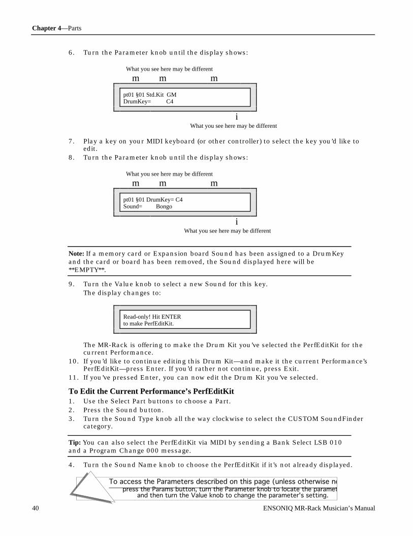
Chapter 4—Parts
To access the Parameters described on this page (unless otherwise noted):press the Params button, turn the Parameter knob to locate the parameter,
and then turn the Value knob to change the parameter's setting.
40 ENSONIQ MR-Rack Musician’s Manual
6. Turn the Parameter knob until the display shows:
What you see here may be different
m m m
pt01 §01 Std.Kit GMDrumKey= C4
iWhat you see here may be different
7. Play a key on your MIDI keyboard (or other controller) to select the key you’d like toedit.
8. Turn the Parameter knob until the display shows:
What you see here may be different
m m m
pt01 §01 DrumKey= C4Sound= Bongo
iWhat you see here may be different
Note: If a memory card or Expansion board Sound has been assigned to a DrumKeyand the card or board has been removed, the Sound displayed here will be**EMPTY**.
9. Turn the Value knob to select a new Sound for this key.The display changes to:
Read-only! Hit ENTERto make PerfEditKit.
The MR-Rack is offering to make the Drum Kit you’ve selected the PerfEditKit for thecurrent Performance.
10. If you’d like to continue editing this Drum Kit—and make it the current Performance’sPerfEditKit—press Enter. If you’d rather not continue, press Exit.
11. If you’ve pressed Enter, you can now edit the Drum Kit you’ve selected.
To Edit the Current Performance’s PerfEditKit1. Use the Select Part buttons to choose a Part.2. Press the Sound button.3. Turn the Sound Type knob all the way clockwise to select the CUSTOM SoundFinder
category.
Tip: You can also select the PerfEditKit via MIDI by sending a Bank Select LSB 010and a Program Change 000 message.
4. Turn the Sound Name knob to choose the PerfEditKit if it’s not already displayed.

Chapter 4—Parts
To access the Parameters described on this page (unless otherwise noted):press the Params button, turn the Parameter knob to locate the parameter,
and then turn the Value knob to change the parameter's setting.
ENSONIQ MR-Rack Musician’s Manual 41
5. Press the Params button.6. Turn the Parameter knob to find the Drum Kit parameter you want to change and start
editing.
Selecting a DrumKey for EditingMR-Rack Drum Kits are edited one key at a time. The first thing you need to do to edit a Kitis to select the key—called a DrumKey—you want to start with.
The following parameter is only present when the Part being edited uses a Drum Kit.
To Select a DrumKey for Editing1. Use the method described in “To Edit a Drum Kit You’ve Chosen for a Part” or “To Edit
the Current Performance’s PerfEditKit” above to prepare to edit a Drum Kit.2. Turn the Parameter knob until the display shows:
What you see here may be different
m m m
pt01 §01 GM Std. KitDrumKey= C4
iWhat you see here may be different
3. Press a key on your MIDI keyboard or controller to select a DrumKey to edit, or dial inthe desired key with the Value knob (Middle C is C4). Drum Kits can go from the B twooctaves below Middle C (B1) to the D three octaves above it (D7).
Changing the Source of a DrumKey’s SoundEach key in a Drum Kit can use a Sound from any of these Sound Type categories:
• CRD—Sounds from a data card if there’s one installed• EXP—Sounds from expansion boards if there are any installed• DRM—Drum Sounds in the MR-Rack’s ROM and RAM memory banks• GM—General MIDI Sounds• ROM—all the Sounds in the MR-Rack’s ROM memory• RAM—all the Sounds in the MR-Rack’s RAM memory• ALL—this category includes all of the above. The ALL Sound Type can be especially
handy, since it lists Sounds alphabetically
Note: When you assign a Sound to a DrumKey, the Key makes note of the location ofthe Sound in the MR-Rack’s memory. When you play the DrumKey, it looks to thatlocation and uses the Sound it finds there. If you edit the Sound or replace it, theDrumKey will play the edited version or the Sound you’ve replaced it with. If you’veassigned a memory card or expansion board Sound to the DrumKey, and removedthe card or board, the DrumKey will be unable to locate its Sound and will producesilence when played.
The following parameter is only present when the Part being edited uses a Drum Kit.
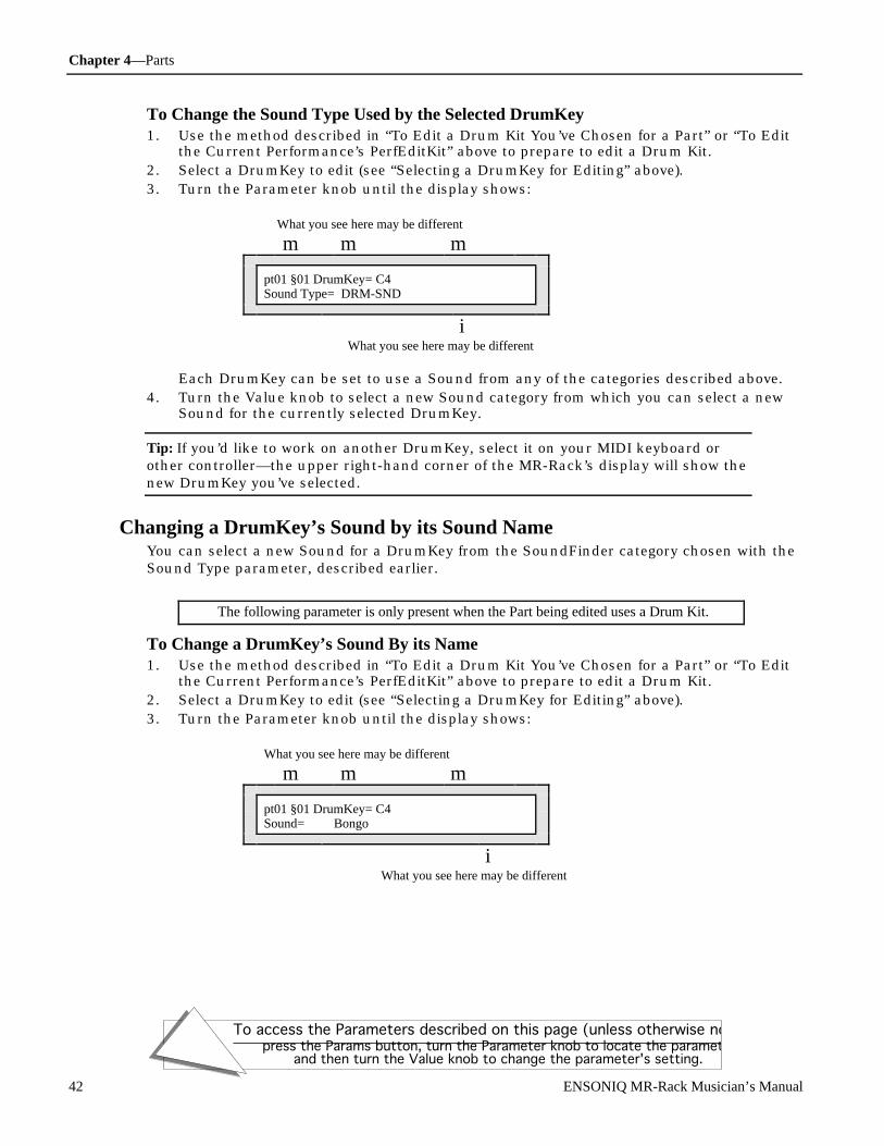
Chapter 4—Parts
To access the Parameters described on this page (unless otherwise noted):press the Params button, turn the Parameter knob to locate the parameter,
and then turn the Value knob to change the parameter's setting.
42 ENSONIQ MR-Rack Musician’s Manual
To Change the Sound Type Used by the Selected DrumKey1. Use the method described in “To Edit a Drum Kit You’ve Chosen for a Part” or “To Edit
the Current Performance’s PerfEditKit” above to prepare to edit a Drum Kit.2. Select a DrumKey to edit (see “Selecting a DrumKey for Editing” above).3. Turn the Parameter knob until the display shows:
What you see here may be different
m m m
pt01 §01 DrumKey= C4Sound Type= DRM-SND
iWhat you see here may be different
Each DrumKey can be set to use a Sound from any of the categories described above.4. Turn the Value knob to select a new Sound category from which you can select a new
Sound for the currently selected DrumKey.
Tip: If you’d like to work on another DrumKey, select it on your MIDI keyboard orother controller—the upper right-hand corner of the MR-Rack’s display will show thenew DrumKey you’ve selected.
Changing a DrumKey’s Sound by its Sound NameYou can select a new Sound for a DrumKey from the SoundFinder category chosen with theSound Type parameter, described earlier.
The following parameter is only present when the Part being edited uses a Drum Kit.
To Change a DrumKey’s Sound By its Name1. Use the method described in “To Edit a Drum Kit You’ve Chosen for a Part” or “To Edit
the Current Performance’s PerfEditKit” above to prepare to edit a Drum Kit.2. Select a DrumKey to edit (see “Selecting a DrumKey for Editing” above).3. Turn the Parameter knob until the display shows:
What you see here may be different
m m m
pt01 §01 DrumKey= C4Sound= Bongo
iWhat you see here may be different
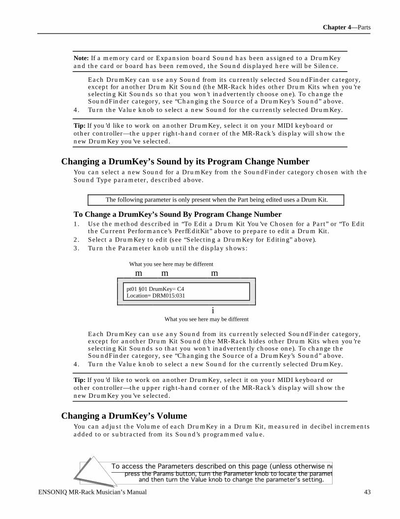
Chapter 4—Parts
To access the Parameters described on this page (unless otherwise noted):press the Params button, turn the Parameter knob to locate the parameter,
and then turn the Value knob to change the parameter's setting.
ENSONIQ MR-Rack Musician’s Manual 43
Note: If a memory card or Expansion board Sound has been assigned to a DrumKeyand the card or board has been removed, the Sound displayed here will be Silence.
Each DrumKey can use any Sound from its currently selected SoundFinder category,except for another Drum Kit Sound (the MR-Rack hides other Drum Kits when you’reselecting Kit Sounds so that you won’t inadvertently choose one). To change theSoundFinder category, see “Changing the Source of a DrumKey’s Sound” above.
4. Turn the Value knob to select a new Sound for the currently selected DrumKey.
Tip: If you’d like to work on another DrumKey, select it on your MIDI keyboard orother controller—the upper right-hand corner of the MR-Rack’s display will show thenew DrumKey you’ve selected.
Changing a DrumKey’s Sound by its Program Change NumberYou can select a new Sound for a DrumKey from the SoundFinder category chosen with theSound Type parameter, described above.
The following parameter is only present when the Part being edited uses a Drum Kit.
To Change a DrumKey’s Sound By Program Change Number1. Use the method described in “To Edit a Drum Kit You’ve Chosen for a Part” or “To Edit
the Current Performance’s PerfEditKit” above to prepare to edit a Drum Kit.2. Select a DrumKey to edit (see “Selecting a DrumKey for Editing” above).3. Turn the Parameter knob until the display shows:
What you see here may be different
m m m
pt01 §01 DrumKey= C4Location= DRM015:031
iWhat you see here may be different
Each DrumKey can use any Sound from its currently selected SoundFinder category,except for another Drum Kit Sound (the MR-Rack hides other Drum Kits when you’reselecting Kit Sounds so that you won’t inadvertently choose one). To change theSoundFinder category, see “Changing the Source of a DrumKey’s Sound” above.
4. Turn the Value knob to select a new Sound for the currently selected DrumKey.
Tip: If you’d like to work on another DrumKey, select it on your MIDI keyboard orother controller—the upper right-hand corner of the MR-Rack’s display will show thenew DrumKey you’ve selected.
Changing a DrumKey’s VolumeYou can adjust the Volume of each DrumKey in a Drum Kit, measured in decibel incrementsadded to or subtracted from its Sound’s programmed value.

Chapter 4—Parts
To access the Parameters described on this page (unless otherwise noted):press the Params button, turn the Parameter knob to locate the parameter,
and then turn the Value knob to change the parameter's setting.
44 ENSONIQ MR-Rack Musician’s Manual
The following parameter is only present when the Part being edited uses a Drum Kit.
To Change a DrumKey’s Volume1. Use the method described in “To Edit a Drum Kit You’ve Chosen for a Part” or “To Edit
the Current Performance’s PerfEditKit” above to prepare to edit a Drum Kit.2. Select a DrumKey to edit (see “Selecting a DrumKey for Editing” above).3. Turn the Parameter knob until the display shows:
What you see here may be different
m m m
pt01 §01 DrumKey= C4Key Volume= -1dB
iWhat you see here may be different
Each DrumKey’s Volume may be set anywhere from -50 to +14 dB (deciBels).4. Turn the Value knob to adjust the Volume of the currently selected DrumKey to the
desired level.
Tip: If you’d like to work on another DrumKey, select it on your MIDI keyboard orother controller—the upper right-hand corner of the MR-Rack’s display will show thenew DrumKey you’ve selected.
Changing a DrumKey’s PanningYou can shift the stereo panning of each DrumKey in a Drum Kit, from Left -64 to Right+63. If the DrumKey is using a stereo Sound, both sides of the Sound will shiftproportionally, retaining their stereo separation.
The following parameter is only present when the Part being edited uses a Drum Kit.
To Change a DrumKey’s Panning1. Use the method described in “To Edit a Drum Kit You’ve Chosen for a Part” or “To Edit
the Current Performance’s PerfEditKit” above to prepare to edit a Drum Kit.2. Select a DrumKey to edit (see “Selecting a DrumKey for Editing” above).3. Turn the Parameter knob until the display shows:
What you see here may be different
m m m
pt01 §01 DrumKey= C4Key Pan= Right +40
iWhat you see here may be different
Each DrumKey’s stereo position may be set anywhere from Left -64 to Right +63.4. Turn the Value knob to shift the panning of the currently selected DrumKey to the
desired position in the stereo field.

Chapter 4—Parts
To access the Parameters described on this page (unless otherwise noted):press the Params button, turn the Parameter knob to locate the parameter,
and then turn the Value knob to change the parameter's setting.
ENSONIQ MR-Rack Musician’s Manual 45
Tip: If you’d like to work on another DrumKey, select it on your MIDI keyboard orother controller—the upper right-hand corner of the MR-Rack’s display will show thenew DrumKey you’ve selected.
Changing a DrumKey’s EffectEach DrumKey in a Drum Kit has its own Effect bus assignment so that it can be sent toany of the standard MR-Rack stereo Effect busses:
• Insert • MediumReverb• Chorus • WetReverb• LightReverb • Dry
For a complete explanation of the MR-Rack’s Effects, see Chapter 5.
Tip: When a Drum Kit is assigned to a Part, repeatedly pressing the Params buttonwill toggle between this parameter and the Part MIDI Channel parameter.
The following parameter is only present when the Part being edited uses a Drum Kit.
To Change a DrumKey’s Effect1. Use the method described in “To Edit a Drum Kit You’ve Chosen for a Part” or “To Edit
the Current Performance’s PerfEditKit” above to prepare to edit a Drum Kit.2. Select a DrumKey to edit (see “Selecting a DrumKey for Editing” above).3. Turn the Parameter knob until the display shows:
What you see here may be different
m m m
pt01 §01 DrumKey= C4FX Bus= MediumReverb
iWhat you see here may be different
Each DrumKey can be sent to any of the MR-Rack’s Effects busses: Insert, Chorus,LightReverb, MediumReverb, WetReverb or Dry.
4. Turn the Value knob to select the appropriate Effect bus for the currently selectedDrumKey.
Tip: If you’d like to work on another DrumKey, select it on your MIDI keyboard orother controller—the upper right-hand corner of the MR-Rack’s display will show thenew DrumKey you’ve selected.
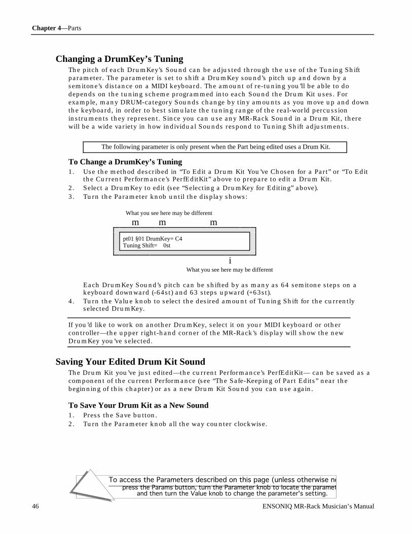
Chapter 4—Parts
To access the Parameters described on this page (unless otherwise noted):press the Params button, turn the Parameter knob to locate the parameter,
and then turn the Value knob to change the parameter's setting.
46 ENSONIQ MR-Rack Musician’s Manual
Changing a DrumKey’s TuningThe pitch of each DrumKey’s Sound can be adjusted through the use of the Tuning Shiftparameter. The parameter is set to shift a DrumKey sound’s pitch up and down by asemitone’s distance on a MIDI keyboard. The amount of re-tuning you’ll be able to dodepends on the tuning scheme programmed into each Sound the Drum Kit uses. Forexample, many DRUM-category Sounds change by tiny amounts as you move up and downthe keyboard, in order to best simulate the tuning range of the real-world percussioninstruments they represent. Since you can use any MR-Rack Sound in a Drum Kit, therewill be a wide variety in how individual Sounds respond to Tuning Shift adjustments.
The following parameter is only present when the Part being edited uses a Drum Kit.
To Change a DrumKey’s Tuning1. Use the method described in “To Edit a Drum Kit You’ve Chosen for a Part” or “To Edit
the Current Performance’s PerfEditKit” above to prepare to edit a Drum Kit.2. Select a DrumKey to edit (see “Selecting a DrumKey for Editing” above).3. Turn the Parameter knob until the display shows:
What you see here may be different
m m m
pt01 §01 DrumKey= C4Tuning Shift= 0st
iWhat you see here may be different
Each DrumKey Sound’s pitch can be shifted by as many as 64 semitone steps on akeyboard downward (-64st) and 63 steps upward (+63st).
4. Turn the Value knob to select the desired amount of Tuning Shift for the currentlyselected DrumKey.
If you’d like to work on another DrumKey, select it on your MIDI keyboard or othercontroller—the upper right-hand corner of the MR-Rack’s display will show the newDrumKey you’ve selected.
Saving Your Edited Drum Kit SoundThe Drum Kit you’ve just edited—the current Performance’s PerfEditKit— can be saved as acomponent of the current Performance (see “The Safe-Keeping of Part Edits” near thebeginning of this chapter) or as a new Drum Kit Sound you can use again.
To Save Your Drum Kit as a New Sound1. Press the Save button.2. Turn the Parameter knob all the way counter clockwise.

Chapter 4—Parts
To access the Parameters described on this page (unless otherwise noted):press the Params button, turn the Parameter knob to locate the parameter,
and then turn the Value knob to change the parameter's setting.
ENSONIQ MR-Rack Musician’s Manual 47
3. Turn the Value knob until the display shows:
Hit ENTER to:Save:ThisPart’sSound
4. Press the Enter button.If the System Write Protect parameter is set to Prompt, the display will show:
System Write ProtectOn! ENTER Overrides.
This display is offered as a double-check for you, to make sure you really want to saveyour Drum Kit. If you’d like to avoid this prompt in the future, see “Protecting the MR-Rack’s Memory” in Chapter 3 .
5. If you’d like to cancel the operation, press the Exit button. If you’d like to proceed, pressthe Enter button. The display now allows you to name your Drum Kit:
Left knob function Right knob function
m m
Left:pos Right:charNew Name= P erfEditKit
iNote this underline
The Parameter knob (left) is used to select the character position within the name. Youwill know which character is selected because the position in the display will beunderlined. Turning the knob clockwise moves the location to the right, andcounterclockwise moves it to the left. The Value knob (right) is used to select the alpha-numeric character for that location.
6. Use the Parameter and Value knobs to select a name for your Drum Kit.7. When you’ve named your Drum Kit, press the Enter button.8. Use the Value knob to select a SoundFinder type for your Drum Kit. Choose a category
that will make it easy for you to locate your Drum Kit later on. For a complete list ofSoundFinder types, see Chapter 9.
9. When you’ve defined a SoundFinder type, press the Enter button.10. Use the Parameter knob to select either:
• RAM—to save the Drum Kit to the MR-Rack’s internal RAM memory• CRD—to save the Drum Kit to an installed data card (see “Formatting a PCMCIA
Card” in Chapter 6 for instructions on how to prepare a data card for storage)11. Use the Value knob to select a specific location for your Drum Kit.12. When you’ve selected a location for your Drum Kit, press the Enter button. The display
momentarily confirms the successful completion of your command, and then selects thenewly-saved Sound.
U sing RP N s and NR P N s t o Edit P ar t Par ame t e r sMIDI allows for a special category of controllers called RPNs (for “Registered Parameter

Chapter 4—Parts
To access the Parameters described on this page (unless otherwise noted):press the Params button, turn the Parameter knob to locate the parameter,
and then turn the Value knob to change the parameter's setting.
48 ENSONIQ MR-Rack Musician’s Manual
Numbers”) and NRPNs (for “Non-Registered Parameter Numbers”). Many of the Partparameters can be edited via RPNs and NRPNs. If this is the case, the parameter’sdescription found in this chapter will list the appropriate RPN or NRPN.
RPN MIDI messages must adhere to a specific structure in order to be properly understoodby receiving devices such as the MR-Rack. They must include the following components:
• A continuous controller status byte for the Part’s MIDI channel• MIDI controller 101—the RPN MSB—with a value of 000• MIDI controller 100—the RPN LSB—with the RPN value listed in the description of the
relevant Part parameter• MIDI controller 006—Data Entry—with the value to which you’d like to set the
parameter. The values displayed for each parameter correspond to one of 128 possibleMIDI values (which run from 000 up to 127). You can count the parameter valuesdisplayed on the MR-Rack, beginning from 000, to locate the corresponding Data Entryvalue you’ll want to send to the MR.
NRPN MIDI messages must also adhere to a specific structure in order to be properlyunderstood by receiving devices such as the MR-Rack. They must include the followingcomponents:
• A continuous controller status byte for the Part’s MIDI channel• MIDI controller 099—the NRPN MSB—with a value of 000• MIDI Controller 098—the NRPN LSB—with the NRPN value listed in the description of
the relevant Part parameter• MIDI controller 006—Data Entry—with the value to which you’d like to set the
parameter. The values displayed for each parameter correspond to one of 128 possibleMIDI values (which run from 000 up to 127). You can count the parameter valuesdisplayed on the MR-Rack, beginning from 000, to locate the corresponding Data Entryvalue you’ll want to send to the MR.
Tip: For a complete listing of the RPNs and NRPNs to which the MR-Rack responds,see “Registered and Non-Registered Parameters (RPN/NRPN)” in Chapter 9.

Chapter 5—Effects
ENSONIQ MR-Rack Musician’s Manual 1
Ch apt e r 5Ef f e ct s
This chapter explains the MR-Rack Effects. To access the functions you’ll find in thischapter, press the Effects button, except where noted. When you press the Effects button,its yellow LED will light.
Performance System Effects
Sound Params Mute
Part
Bypass
The MR-Rack provides many options for routing, assigning and editing Effects. Each ofthese options is called a parameter. When you change the setting of a parameter, you areediting the parameter’s value.
To select Effect parameters, turn the Parameters knob. To edit an Effect parameter’s value,turn the Value knob.
Parameter Value
U nde r st anding the M R - R ac k Ef f ec t sThe MR-Rack Effects are designed to provide excellent sound quality and considerableflexibility. Take a few moments to familiarize yourself with the way they work so that youcan fully take advantage of all they have to offer.
Every Performance contains an Effect setup comprised of several components. To start with,each Performance offers four stereo Effect options:
• an Insert Effect• a Global Chorus• a Global Reverb• Dry (or no Effect)
Chapter 5—Effects
To access the Parameters described on this page (unless otherwise noted):
Press the Effects button, and follow the instructions above.
2 ENSONIQ MR-Rack Musician’s Manual
Insert EffectsMany MR-Rack Sounds are programmed with their own Insert Effects. Insert Effects arepowerful, fully editable Effect programs that cover a broad range of applications. For adetailed list of the Insert Effects and their parameters, see Chapter 8.
In each Performance, one Part can be designated as the Insert Control Part. When a Soundwith an Insert Effect is selected for the Insert Control Part, the sound’s Insert Effectbecomes the current Performance’s Insert Effect. A Performance’s Insert Control Part isdesignated by setting the InsertContrlPart parameter, which is discussed later in thischapter. A Performance’s Insert Effect can also be chosen manually, as described in"Working with the Insert Effect," later in this chapter.
Note: To ensure that you’re hearing a Sound’s intended Effect, the Sound must beassigned to the Performance’s Insert Control Part. Sounds assigned to other Partswill not necessarily be heard through their original Effect.
Any of the Performance’s other Parts may also use the Insert Effect. See UnderstandingEffect Busses later in this chapter for more details.
The Insert Effect is completely editable. Its output can be routed to the Global Chorus, theGlobal Reverb, or both, before traveling finally to either the MR-Rack’s Main or Aux Outs.See “Determining Which MR-Rack Outputs the Insert Effect Will Use” later in this chapterfor details.
Global ChorusEach Performance contains a high-quality Global Chorus Effect, which can be edited to suityour needs. The MR-Rack offers the following Chorus presets as starting points:
• MR Chorus • Padmaker • Vintage• MR Classic • Slow & Deep • Wide• Fast & Wide • Super Slow • Slow Rotary• Halleluiah • Thick • Fast Rotary
The Global Chorus Preset parameter, described later in this chapter, is used to select thevariation of chorus used in a Performance. Any Part in a Performance may utilize the GlobalChorus. See Understanding Effect Busses later in this chapter for more details. The GlobalChorus can be routed to either the MR-Rack’s Main or Aux Outs, as determined by thesetting of the Output Assign for Global Chorus parameter, described in “Determining WhichMR-Rack Outputs the Global Chorus Will Use,” later in this chapter.
Global ReverbEach Performance contains a high-quality Global Reverb Effect, which you can edit to suityour needs.
The MR-Rack offers the following Reverb presets as starting points:
• Smooth Plate • Big Room • Bright• Large Hall • Small Room • Huge Place• Small Hall • Reflections
The Global Reverb Preset parameter, described later in this chapter, is used to select thevariation of reverb used in a Performance. Any Part in a Performance may utilize the GlobalReverb. See Understanding Effect Busses below for more details. The Global Reverb can be

Chapter 5—Effects
To access the Parameters described on this page (unless otherwise noted):
Press the Effects button, and follow the instructions above.
ENSONIQ MR-Rack Musician’s Manual 3
routed to either the MR-Rack’s Main or Aux Outs, as determined by the setting of theOutput Assign for Global Reverb parameter, described in “Determining Which MR-RackOutputs the Global Reverb Will Use,” later in this chapter.
DryPart Sounds don’t have to go through any of the Effects above—they can remain dry byselecting the Dry Effect option. Dry Sounds can be routed to either the MR-Rack’s Main orAux Outs, as determined by the setting of the Output Assign for Dry FX Bus parameter,described “To Select the Dry Bus’s Output Routing,” later in this chapter.
U nde r st anding Ef f e c t Busse sIn order to provide maximum flexibility, the MR-Rack offers six stereo pathways, or busses,to the Effects:
• the Insert FX Bus• the Chorus FX Bus• the LightReverb FX Bus• the MediumReverb FX Bus• the WetReverb FX Bus• the Dry FX Bus
Parts are routed to an Effect bus with the setting of the FX Bus Part Parameter. See “AddingEffects to Part Sounds” in Chapter 4 for a more detailed description of this parameter.
The Insert BusWhen a Part is assigned to the Insert bus, its Sound is routed to a wet/dry control. Thewet/dry control determines the relative balance between the Sound as it is before goingthrough the Insert Effect (dry), and as it is after going through the Insert Effect (wet).
The Insert Effect mix may then be sent into the Global Reverb. It can also be routed to theGlobal Chorus, where it encounters a second wet/dry control. In this case, the “dry”component is the Insert Effect mix, and the “wet” is the Insert Effect mix after it’s beenthrough the Chorus.
Any Part Sounds assigned to the Insert bus will use the MR-Rack outputs chosen by theOutput Assign for Insert Effect parameter, described later in this chapter.
The Chorus BusThe Chorus bus can access both a Performance’s Chorus and Reverb. When a Part isassigned to the Chorus bus, its Sound is routed to a wet/dry control. The wet/dry controldetermines the relative balance between the Sound as it is before going through the GlobalChorus (dry), and as it is after the going through the Chorus (wet). This Chorus mix maythen be sent to the Global Reverb.
Any Part Sounds assigned to the Chorus bus will use the MR-Rack outputs chosen by theOutput Assign for Global Chorus parameter, described later in this chapter.

Chapter 5—Effects
To access the Parameters described on this page (unless otherwise noted):
Press the Effects button, and follow the instructions above.
4 ENSONIQ MR-Rack Musician’s Manual
The Three Reverb Busses
The LightReverb Bus
The MediumReverb Bus
The WetReverb BusFor reverb, arguably the most important Effect of all, the MR-Rack provides three separatebusses for routing Parts—and their Sounds—to a Performance’s Reverb. It’s not uncommonto want some Sounds to have a little reverb; others may require a bit more, and perhapsother Sounds need a lot of reverb.
The MR-Rack provides a solution to these several needs by offering a LightReverb bus forPart Sounds requiring just a touch of reverb, a MediumReverb bus for those wanting a bitmore, and a WetReverb bus for Sounds that need an even greater amount of reverb. You canalso determine how much reverb will be used by each of the buses, since each has its ownsend amount into the Reverb Effect. (See “Setting the Reverb Amounts for the LightReverb,MediumReverb and WetReverb Effect Busses” later in this chapter.) Once you’ve set thebusses to their desired send amounts, you can assign Parts to the appropriate bus.
Any Part Sounds assigned to either of the three Reverb busses will use the MR-Rack outputschosen by the Output Assign for Global Reverb parameter, described later in this chapter.
The Dry BusSounds assigned to the Dry bus will not be processed by the Insert Effect, the GlobalChorus or the Global Reverb—they’ll go directly to the MR-Rack outputs chosen by theOutput Assign for Dry FX Bus parameter, described later in this chapter.
Understanding the Special Alt. FX BusThere’s one more special Effect bus setting used by MR-Rack sounds, called the Alt. FX Bus.If a Sound which uses an Insert Effect is chosen for a Part that’s not the Insert Control Part,the Alt. FX Bus setting can provide a “second-best” Effect choice. It will perform thisfunction if the System AutoSelect FXBus parameter is switched on (see Chapter 3). The Alt.FX Bus is a parameter within the MR’s Sounds that can be edited directly using the UnisynSound editor. In addition, when you set a Part’s FX Bus parameter to Chorus, LightReverb,MediumReverb, WetReverb or Dry, and save the Part’s Sound, the Alt. FX Bus parameterwithin the Sound is set to the same value.

Chapter 5—Effects
To access the Parameters described on this page (unless otherwise noted):
Press the Effects button, and follow the instructions above.
ENSONIQ MR-Rack Musician’s Manual 5
A D iagr am of t he MR - R ac k Ef f e c t s
Global Reverb(all wet)
WetReverb
MediumReverb
LightReverb
GlobalReverb Amt64-127
GlobalReverb Amt32-95
GlobalReverb Amt0-63
Insert Effect
Chorus
Insert
Dry
GlobalReverb Amount0-127
StereoMain
Outputs
StereoAux
Outputs
System PageAuxToMainOutsswitch
Insert EffectOutput Assign
Reverb Return Level0-127
Part FX Bus Select
ESP
Dry FX BusOutput Assign
GlobalReverbOutputAssign
GlobalChorusOutputAssign
Part 1
Part 2
Part 3
Part 4
Part 5
Part 6
Part 7
Part 8
Part 9
Part 10
Part 11
Part 12
Part 13
Part 14
Part 15
Part 16
OTTO
GlobalReverb Amount0-127
Input MixFull Dry toFull Wet
Input MixFull Dry toFull Wet
GlobalChorus MixFull Dry toFull Wet
Global Chorus
Note: In the above diagram, all arrows represent stereo signal paths. Hollow circles representparameters that can be edited. The circle with a “+” means the signals are summed together.Arrows with a “bump” in them are not connected to the line that they cross. OTTO is the voicechip—actually, the MR-Rack contains two OTTOs—and ESP is the effects chip in the MR-Rack.
Wor king wit h t he Inse r t Ef f e c t The Insert Effect can be directly selected in two ways:
• The Insert Effect can be installed by selecting a new Sound for the currentPerformance’s designated Insert Control Part. If the Sound is programmed with anInsert Effect, the Effect becomes the Performance’s Insert Effect. This method isdescribed in “Using the Insert Control Part to Determine the Insert Effect,” later in thischapter.
• The Insert Effect can be selected manually by editing the Insert Effect. This method isdescribed in “Manually Selecting an Insert Effect,” later in this chapter.
Note: When a new Insert Effect is selected using either method, all real-time controlparameters (described later in this chapter) are reset to their default settings.

Chapter 5—Effects
To access the Parameters described on this page (unless otherwise noted):
Press the Effects button, and follow the instructions above.
6 ENSONIQ MR-Rack Musician’s Manual
Using the Insert Control PartMany MR-Rack Sounds are programmed with their own Insert Effects. In each Performance,one Part can be designated as the Insert Control Part, and the Sound it uses contributes itsEffect to the Performance.
Note: The Insert Control Part is also used for real-time control of the Insert Effect.MIDI messages received on the Insert Control Part’s MIDI channel can be used tomodulate the Insert Effect.
To Designate a Performance’s Insert Control Part1. Press the Effects button if its yellow LED is not already lit.2. Turn the Parameter knob until the display shows:
Effects:InsertContrlPart= 01
iWhat you see here may be different
The Insert Control Part parameter can be set to:• Off—selecting Sounds on any Parts will not change the Insert Effect• 01-16—any new Sound selected on the Part chosen here will have its programmed
Insert Effect installed as the Performance’s Insert Effect3. Use the Value knob to set the displayed parameter to the desired value.
Note: If a Sound with no Insert Effect is selected for the Insert Control Part, thecurrent Insert Effect will remain unchanged.
Using the Insert Control Part to Determine the Insert EffectIf a Sound is programmed with an Insert Effect, selecting it for use by the Insert ControlPart will cause the Sound’s Insert Effect to be installed as the current Performance’s InsertEffect. Once installed, the new Insert Effect can be customized using the editing proceduresdescribed in this chapter.
Note: If a Sound chosen for the Insert Control Part has no Insert Effect, the MR-Rackwill automatically change the Insert Control Part’s routing to the Alt. FX Busprogrammed into the Sound. This occurs regardless of the setting of the AutoSelectFXBus System parameter.
Using the Insert Control Part to Pick Insert Effects Via MIDIYou can select Insert Effects for a Performance via MIDI using the Insert Control Part. Selecta Sound that uses the Insert Effect you want, or assign the desired Insert Effect to theSound called “Silence” from the *UTILITY SoundFinder category (Silence is a good choicebecause it doesn’t use up any Sound layers). Save the new Sound using a name that reflectsits Insert Effect. By sending the Sound’s MIDI Bank Select and Program Change to theInsert Control Part, your Insert Effect-only “Sound” will contribute its Insert Effect to thePerformance. You can set up Insert Effect-only “Sounds” for all your favorite Insert Effects.
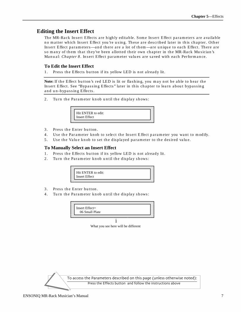
Chapter 5—Effects
To access the Parameters described on this page (unless otherwise noted):
Press the Effects button, and follow the instructions above.
ENSONIQ MR-Rack Musician’s Manual 7
Editing the Insert EffectThe MR-Rack Insert Effects are highly editable. Some Insert Effect parameters are availableno matter which Insert Effect you’re using. These are described later in this chapter. OtherInsert Effect parameters—and there are a lot of them—are unique to each Effect. There areso many of them that they’ve been allotted their own chapter in the MR-Rack Musician’sManual: Chapter 8. Insert Effect parameter values are saved with each Performance.
To Edit the Insert Effect1. Press the Effects button if its yellow LED is not already lit.
Note: If the Effect button’s red LED is lit or flashing, you may not be able to hear theInsert Effect. See “Bypassing Effects” later in this chapter to learn about bypassingand un-bypassing Effects.
2. Turn the Parameter knob until the display shows:
Hit ENTER to edit:Insert Effect
3. Press the Enter button.4. U se t h e Pa r am et er kno b t o sel e ct t he In sert E ffect p ar a met er yo u w an t t o mo di fy. 5. Use the Value knob to set the displayed parameter to the desired value.
To Manually Select an Insert Effect1. Press the Effects button if its yellow LED is not already lit.2. Turn the Parameter knob until the display shows:
Hit ENTER to edit:Insert Effect
3. Press the Enter button.4. Turn the Parameter knob until the display shows:
Insert Effect= 06 Small Plate
iWhat you see here will be different
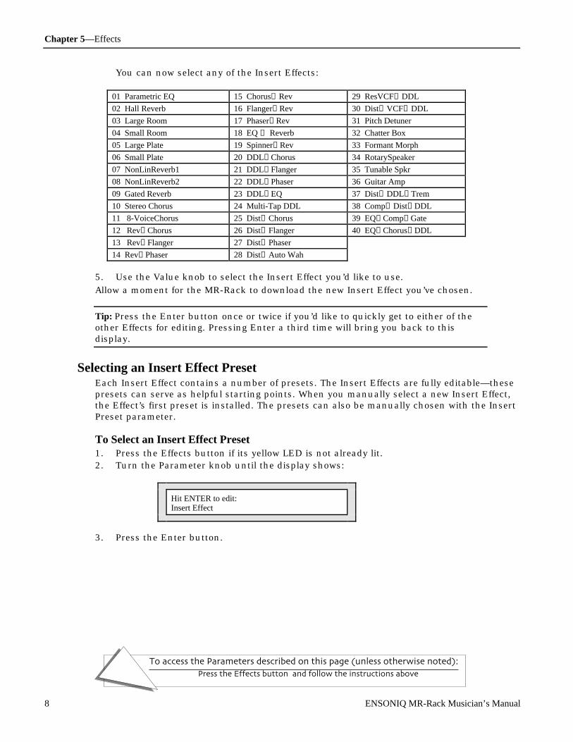
Chapter 5—Effects
To access the Parameters described on this page (unless otherwise noted):
Press the Effects button, and follow the instructions above.
8 ENSONIQ MR-Rack Musician’s Manual
You can now select any of the Insert Effects:
01 Parametric EQ 15 Chorus→Rev 29 ResVCF→DDL
02 Hall Reverb 16 Flanger→Rev 30 Dist→VCF→DDL
03 Large Room 17 Phaser→Rev 31 Pitch Detuner
04 Small Room 18 EQ → Reverb 32 Chatter Box
05 Large Plate 19 Spinner→Rev 33 Formant Morph
06 Small Plate 20 DDL→Chorus 34 RotarySpeaker
07 NonLinReverb1 21 DDL→Flanger 35 Tunable Spkr
08 NonLinReverb2 22 DDL→Phaser 36 Guitar Amp
09 Gated Reverb 23 DDL→EQ 37 Dist→DDL→Trem
10 Stereo Chorus 24 Multi-Tap DDL 38 Comp→Dist→DDL
11 8-VoiceChorus 25 Dist→Chorus 39 EQ→Comp→Gate
12 Rev→Chorus 26 Dist→Flanger 40 EQ→Chorus→DDL
13 Rev→Flanger 27 Dist→Phaser
14 Rev→Phaser 28 Dist→Auto Wah
5. Use the Value knob to select the Insert Effect you’d like to use.
Allow a moment for the MR-Rack to download the new Insert Effect you’ve chosen.
Tip: Press the Enter button once or twice if you’d like to quickly get to either of theother Effects for editing. Pressing Enter a third time will bring you back to thisdisplay.
Selecting an Insert Effect PresetEach Insert Effect contains a number of presets. The Insert Effects are fully editable—thesepresets can serve as helpful starting points. When you manually select a new Insert Effect,the Effect’s first preset is installed. The presets can also be manually chosen with the InsertPreset parameter.
To Select an Insert Effect Preset1. Press the Effects button if its yellow LED is not already lit.2. Turn the Parameter knob until the display shows:
Hit ENTER to edit:Insert Effect
3. Press the Enter button.

Chapter 5—Effects
To access the Parameters described on this page (unless otherwise noted):
Press the Effects button, and follow the instructions above.
ENSONIQ MR-Rack Musician’s Manual 9
4. Turn the Parameter knob until the display shows:
The name of the current Insert Effect
m
Insert: Small PlatePreset= User Preset
Each Insert Effect has a number of presets that you can use or employ as startingpoints for your own Insert Effect editing.When you first dial to the Insert Effect Preset display, the User Preset is selected—itcontains the Insert Effect parameter settings that were in place when the currentPerformance was last saved. If you’ve been editing the current Performance and thinkyou may want to use or tweak the User Preset—but you would like to listen to the otherpresets anyway, to see what they’re like—save the Performance before selecting otherInsert Effect presets. When you select a new preset, the User Preset is discarded, andcan only be retrieved by reselecting the Performance.
5. Use the Value knob to select an Insert Effect Preset you’d like to use.
Tip: Press the Enter button once or twice if you’d like to quickly get to either of theother Effects for editing. Pressing Enter a third time will bring you back to thisdisplay.
Using the Insert FX Bus Input MixWhen a Part is assigned to the Insert FX Bus, its Sound is routed to a wet/dry mix control.The wet/dry control determines the relative balance between the Sound as it is before goingthrough the Insert Effect (dry), and as it is after the going through the Insert Effect (wet).The Insert FX Bus Input Mix parameter provides the wet/dry balance control.
To Set the Insert FX Bus Wet/Dry Input Mix1. Press the Effects button if its yellow LED is not already lit.
If the Effect button’s red LED is lit or flashing, you may not be able to hear the InsertEffect. See “Bypassing Effects” later in this chapter to learn about bypassing and un-bypassing Effects.
2. Turn the Parameter knob until the display shows:
Hit ENTER to edit:Insert Effect
3. Press the Enter button.

Chapter 5—Effects
To access the Parameters described on this page (unless otherwise noted):
Press the Effects button, and follow the instructions above.
10 ENSONIQ MR-Rack Musician’s Manual
4. Turn the Parameter knob until the display shows:
Insert FX Bus:Input Mix= 29.2 Wet
iWhat you see here may be different
You can set the Insert Bus wet/dry mix anywhere from Full Dry (no Insert Effect) to FullWet (all Insert Effect).
5. Use the Value knob to set the Insert FX Bus Input Mix as you prefer.
Tip: Press the Enter button once or twice if you’d like to quickly get to either of theother Effects for editing. Pressing Enter a third time will bring you back to thisdisplay.
Adding Global Reverb to the Insert EffectIt’s often desirable to add some Reverb to Insert Effect Sounds. The MR-Rack allows you todo this by sending some or all of the Insert wet/dry input mix (described above) to theGlobal Reverb. This amount is determined by the Insert FX Bus Global Reverb Amountparameter.
To Add Global Reverb to the Insert Effect1. Press the Effects button if its yellow LED is not already lit.2. Turn the Parameter knob until the display shows:
Hit ENTER to edit:Insert Effect
3. Press the Enter button.4. Turn the Parameter knob until the display shows:
Insert FX Bus:GlobalReverb Amt= 0
iThe number you see here may be different
You can send any amount of the Insert Bus wet/dry mix to the Global Reverb, from 0 to127.
5. Use the Value knob to set the Insert FX Bus Global Reverb Amount send as you prefer.
Tip: Press the Enter button once or twice if you’d like to quickly get to either of theother Effects for editing. Pressing Enter a third time will bring you back to thisdisplay.

Chapter 5—Effects
To access the Parameters described on this page (unless otherwise noted):
Press the Effects button, and follow the instructions above.
ENSONIQ MR-Rack Musician’s Manual 11
Adding Global Chorus to the Insert EffectAfter Sounds have been processed by the Insert Effect, they can be sent into the GlobalChorus, via a wet/dry mix control. The wet/dry control determines the relative balancebetween the Sound as it is after going through the Insert Effect—referred to, in the contextof this mix, as “dry”—and as it is after it’s gone through the Global Chorus (wet). The InsertFX to Global Chorus Mix parameter provides the wet/dry balance control.
To Add Global Chorus to the Insert Effect1. Press the Effects button if its yellow LED is not already lit.2. Turn the Parameter knob until the display shows:
Hit ENTER to edit:Insert Effect
3. Press the Enter button.4. Turn the Parameter knob until the display shows:
Insert FX to GlobalChorus Mix=66.8% Wet
iWhat you see here may be different
You can select the Insert FX to Global Chorus Mix parameter anywhere from Full Dry(the Insert Effect with no Chorus) to Full Wet (the Insert Effect completely Chorused).
5. Use the Value knob to set the Insert FX to Global Chorus Mix as you prefer.
Tip: Press the Enter button once or twice if you’d like to quickly get to either of theother Effects for editing. Pressing Enter a third time will bring you back to thisdisplay.
Modulating the Insert Effect in Real TimeAll of the MR-Rack Insert Effects allow real-time control of their parameters through the useof MIDI control messages received on the Insert Control Part. To set up real-time control ofan Insert Effect, six things must be determined:
• Mod Src—for “Modulation Source,” this parameter allows you to select what you’d liketo use to change an Insert Effect’s parameter in real time
• Mod Src Min—for “Modulation Source Minimum,” this parameter sets a threshold belowwhich MIDI values received from the Mod Src are ignored
• Mod Src Max—for “Modulation Source Maximum,” this parameter sets a thresholdabove which MIDI values received from the Mod Src are ignored
• Dest—for “Modulation Destination,” this parameter chooses the Insert Effect parameteryou’d like to control in real time
• Dest Min—for “Modulation Destination Minimum,” this parameter sets the lowest valuethe destination parameter can be set to by the real-time modulator
• Dest Max—for “Modulation Destination Maximum,” this parameter sets the highestvalue the destination parameter can be set to by the real-time modulator
Chapter 5—Effects
To access the Parameters described on this page (unless otherwise noted):
Press the Effects button, and follow the instructions above.
12 ENSONIQ MR-Rack Musician’s Manual
Choosing a Real-Time Insert Effect ModulatorThe MR-Rack allows you to use a number of real-time Effect modulators:
• Off—no Effect modulation• FullModAmt—to set the Mod Dest to its maximum amount• Velocity—the Mod Dest responds to the quickness, or hardness, of MIDI keystrikes• Vel+Pressure—the Mod Dest responds to the quickness, or hardness, of MIDI keystrikes
combined with the force by which keys, once struck, are pressed down into thekeyboard
• +PosMIDIkey#—the Mod Dest uses the most recent MIDI Key note number as its valuesetting, from 0 for the lowest note of the MIDI pitch range to 127 for the highest note.
• -NegMIDIkey#—the Mod Dest uses the most recent MIDI Key note number as its valuesetting, from 127 for the lowest note of the MIDI pitch range to 0 for the highest note.
• Pressure—the Mod Dest responds to the force by which keys, once struck, are presseddown into the keyboard
• PitchWheel—the Mod Dest responds to the position of a Pitch Bend wheel, with amedian modulation value produced by the wheel at rest in the middle, and with thewheel all the way forward producing the greatest modulation
• ModWheel—the Mod Dest responds to the up/down position of a Modulation wheel,with the wheel all the way forward producing the greatest modulation
• Wheel+Press—the Mod Dest responds to the up/down position of a Modulation wheel,combined with the force by which keys, once struck, are pressed down into thekeyboard
• FootPedal—MIDI foot pedal messages, with the greatest modulation being produced bythe pedal pushed all the way forward
• Sustain—a sustain pedal, most useful as an Effects modulator when it’s used for aparameter that can be toggled on and off
• Sostenuto—a sostenuto pedal, most useful as an Effects modulator when it’s used for aparameter that can be toggled on and off
• SysCTRL1—System Controller 1, a special real-time modulator that you can add to theMR-Rack’s designated real-time modulators (see “Setting Up New Real-Time Controllers”in Chapter 3 for further information)
• SysCTRL2—System Controller 2, a special real-time modulator that you can add to theMR-Rack’s designated real-time modulators.(see “Setting Up New Real-Time Controllers”in Chapter 3 for further information)
• SysCTRL3—System Controller 3, a special real-time modulator that you can add to theMR-Rack’s designated real-time modulators (see “Setting Up New Real-Time Controllers”in Chapter 3 for further information)
• SysCTRL4—System Controller 4, a special real-time modulator that you can add to theMR-Rack’s designated real-time modulators (see “Setting Up New Real-Time Controllers”in Chapter 3 for further information)
Tip: The MR-Rack provides Part parameters that allow you to disable or limit theInsert Control Part’s reception of many of these modulation sources. See Chapter 4for details.

Chapter 5—Effects
To access the Parameters described on this page (unless otherwise noted):
Press the Effects button, and follow the instructions above.
ENSONIQ MR-Rack Musician’s Manual 13
To Assign a Real-Time Insert Effect Modulator1. Press the Effects button if its yellow LED is not already lit.2. Turn the Parameter knob until the display shows:
Hit ENTER to edit:Insert Effect
3. Press the Enter button.4. Turn the Parameter knob until the display shows:
The name of the current Insert Effect
m
Insert: MR Insert FXMod Src=a Mod Source
iWhat you see here will be different
The Mod Src parameter can be set to any of the modulation sources listed above this“How-To.”
5. Use the Value knob to select a Mod Src you’d like to use.
Tip: Press the Enter button once or twice if you’d like to quickly get to either of theother Effects for editing. Pressing Enter a third time will bring you back to thisdisplay.
Verifying That Your Real-Time Controller Is EnabledWhen using a controller to modulate Effects, it’s a good idea to make sure that the InsertControl Part’s reception of the controller is enabled. If you haven’t already designated anInsert Control Part, see “Using the Insert Control Part” above.
To Confirm That Real-Time Controller Reception Is Enabled1. Press the Params button.2. Use the up and down Select Part buttons to select the Part you’ve designated as the
Insert Control Part.3. Turn the Parameter knob until the display shows the Recv parameter for the controller
you want to use (see Chapter 4 for details).4. Set the parameter to On.
Setting the Real-Time Insert Effect Modulation Reception WindowThe Insert Effect can be set to ignore real-time modulation values that don’t fall within apre-determined range. The Mod Src Min and Max parameters allow you to set the low andhigh limits of that window. If the MR-Rack receives a modulation value higher than the ModSrc Max, it will respond if it had received the highest value within the determined range.
To Set the Insert Effect’s Modulation Reception Window
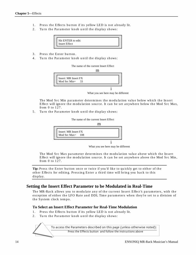
Chapter 5—Effects
To access the Parameters described on this page (unless otherwise noted):
Press the Effects button, and follow the instructions above.
14 ENSONIQ MR-Rack Musician’s Manual
1. Press the Effects button if its yellow LED is not already lit.2. Turn the Parameter knob until the display shows:
Hit ENTER to edit:Insert Effect
3. Press the Enter button.4. Turn the Parameter knob until the display shows:
The name of the current Insert Effect
m
Insert: MR Insert FXMod Src Min= 33
iWhat you see here may be different
The Mod Src Min parameter determines the modulation value below which the InsertEffect will ignore the modulation source. It can be set anywhere below the Mod Src Max,from 0 to 127.
5. Turn the Parameter knob until the display shows:
The name of the current Insert Effect
m
Insert: MR Insert FXMod Src Max= 108
iWhat you see here may be different
The Mod Src Max parameter determines the modulation value above which the InsertEffect will ignore the modulation source. It can be set anywhere above the Mod Src Min,from 0 to 127.
Tip: Press the Enter button once or twice if you’d like to quickly get to either of theother Effects for editing. Pressing Enter a third time will bring you back to thisdisplay.
Setting the Insert Effect Parameter to be Modulated in Real-TimeThe MR-Rack allows you to modulate any of the current Insert Effect’s parameters, with theexception of either the LFO Rate and DDL Time parameters when they’re set to a division ofthe System clock tempo.
To Select an Insert Effect Parameter for Real-Time Modulation1. Press the Effects button if its yellow LED is not already lit.2. Turn the Parameter knob until the display shows:
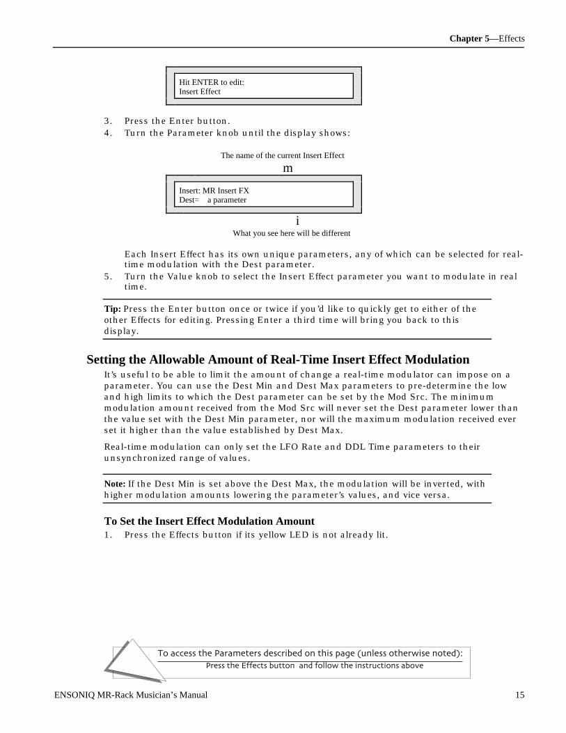
Chapter 5—Effects
To access the Parameters described on this page (unless otherwise noted):
Press the Effects button, and follow the instructions above.
ENSONIQ MR-Rack Musician’s Manual 15
Hit ENTER to edit:Insert Effect
3. Press the Enter button.4. Turn the Parameter knob until the display shows:
The name of the current Insert Effect
m
Insert: MR Insert FXDest= a parameter
iWhat you see here will be different
Each Insert Effect has its own unique parameters, any of which can be selected for real-time modulation with the Dest parameter.
5. Turn the Value knob to select the Insert Effect parameter you want to modulate in realtime.
Tip: Press the Enter button once or twice if you’d like to quickly get to either of theother Effects for editing. Pressing Enter a third time will bring you back to thisdisplay.
Setting the Allowable Amount of Real-Time Insert Effect ModulationIt’s useful to be able to limit the amount of change a real-time modulator can impose on aparameter. You can use the Dest Min and Dest Max parameters to pre-determine the lowand high limits to which the Dest parameter can be set by the Mod Src. The minimummodulation amount received from the Mod Src will never set the Dest parameter lower thanthe value set with the Dest Min parameter, nor will the maximum modulation received everset it higher than the value established by Dest Max.
Real-time modulation can only set the LFO Rate and DDL Time parameters to theirunsynchronized range of values.
Note: If the Dest Min is set above the Dest Max, the modulation will be inverted, withhigher modulation amounts lowering the parameter’s values, and vice versa.
To Set the Insert Effect Modulation Amount1. Press the Effects button if its yellow LED is not already lit.

Chapter 5—Effects
To access the Parameters described on this page (unless otherwise noted):
Press the Effects button, and follow the instructions above.
16 ENSONIQ MR-Rack Musician’s Manual
2. Turn the Parameter knob until the display shows:
Hit ENTER to edit:Insert Effect
3. Press the Enter button.4. Turn the Parameter knob until the display shows:
The name of the current Insert Effect
m
Insert: MR Insert FXDest Min= 33
iWhat you see here may be different
The Dest Min parameter determines the lowest value to which the Dest parameter canbe set by the modulation source. It can be set anywhere from 0 to 127.
5. Turn the Parameter knob until the display shows:
The name of the current Insert Effect
m
Insert: MR Insert FXDest Max= 108
iWhat you see here may be different
The Dest Max parameter determines the highest value to which the Dest parameter canbe set by the modulation source. It can be set anywhere from 0 to 127.If the Min is set above the Max, the modulation will be inverted, with higher modulationamounts lowering the parameter’s values, and vice versa.
Tip: Press the Enter button once or twice if you’d like to quickly get to either of theother Effects for editing. Pressing Enter a third time will bring you back to thisdisplay.
Determining Which MR-Rack Outputs the Insert Effect Will UseYou can route the Insert Effect to the MR-Rack’s rear-panel Main or Aux output jacks. Thiscan be convenient for isolating Insert Effect Sounds to their own outputs.
To Set the Insert Effect’s Output Routing1. Press Enter.
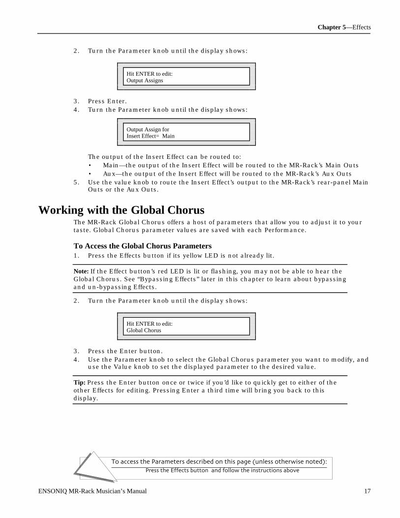
Chapter 5—Effects
To access the Parameters described on this page (unless otherwise noted):
Press the Effects button, and follow the instructions above.
ENSONIQ MR-Rack Musician’s Manual 17
2. Turn the Parameter knob until the display shows:
Hit ENTER to edit:Output Assigns
3. Press Enter.4. Turn the Parameter knob until the display shows:
Output Assign forInsert Effect= Main
The output of the Insert Effect can be routed to:• Main—the output of the Insert Effect will be routed to the MR-Rack’s Main Outs• Aux—the output of the Insert Effect will be routed to the MR-Rack’s Aux Outs
5. Use the value knob to route the Insert Effect’s output to the MR-Rack’s rear-panel MainOuts or the Aux Outs.
Wor king wit h t he Global C hor usThe MR-Rack Global Chorus offers a host of parameters that allow you to adjust it to yourtaste. Global Chorus parameter values are saved with each Performance.
To Access the Global Chorus Parameters1. Press the Effects button if its yellow LED is not already lit.
Note: If the Effect button’s red LED is lit or flashing, you may not be able to hear theGlobal Chorus. See “Bypassing Effects” later in this chapter to learn about bypassingand un-bypassing Effects.
2. Turn the Parameter knob until the display shows:
Hit ENTER to edit:Global Chorus
3. Press the Enter button.4. Use the Parameter knob to select the Global Chorus parameter you want to modify, and
use the Value knob to set the displayed parameter to the desired value.
Tip: Press the Enter button once or twice if you’d like to quickly get to either of theother Effects for editing. Pressing Enter a third time will bring you back to thisdisplay.
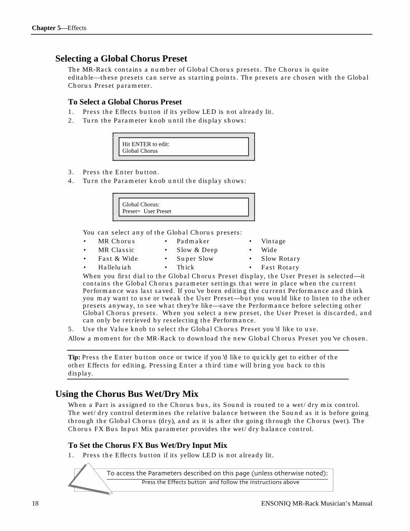
Chapter 5—Effects
To access the Parameters described on this page (unless otherwise noted):
Press the Effects button, and follow the instructions above.
18 ENSONIQ MR-Rack Musician’s Manual
Selecting a Global Chorus PresetThe MR-Rack contains a number of Global Chorus presets. The Chorus is quiteeditable—these presets can serve as starting points. The presets are chosen with the GlobalChorus Preset parameter.
To Select a Global Chorus Preset1. Press the Effects button if its yellow LED is not already lit.2. Turn the Parameter knob until the display shows:
Hit ENTER to edit:Global Chorus
3. Press the Enter button.4. Turn the Parameter knob until the display shows:
Global Chorus:Preset= User Preset
You can select any of the Global Chorus presets:• MR Chorus • Padmaker • Vintage• MR Classic • Slow & Deep • Wide• Fast & Wide • Super Slow • Slow Rotary• Halleluiah • Thick • Fast RotaryWhen you first dial to the Global Chorus Preset display, the User Preset is selected—itcontains the Global Chorus parameter settings that were in place when the currentPerformance was last saved. If you’ve been editing the current Performance and thinkyou may want to use or tweak the User Preset—but you would like to listen to the otherpresets anyway, to see what they’re like—save the Performance before selecting otherGlobal Chorus presets. When you select a new preset, the User Preset is discarded, andcan only be retrieved by reselecting the Performance.
5. Use the Value knob to select the Global Chorus Preset you’d like to use.
Allow a moment for the MR-Rack to download the new Global Chorus Preset you’ve chosen.
Tip: Press the Enter button once or twice if you’d like to quickly get to either of theother Effects for editing. Pressing Enter a third time will bring you back to thisdisplay.
Using the Chorus Bus Wet/Dry MixWhen a Part is assigned to the Chorus bus, its Sound is routed to a wet/dry mix control.The wet/dry control determines the relative balance between the Sound as it is before goingthrough the Global Chorus (dry), and as it is after the going through the Chorus (wet). TheChorus FX Bus Input Mix parameter provides the wet/dry balance control.
To Set the Chorus FX Bus Wet/Dry Input Mix1. Press the Effects button if its yellow LED is not already lit.

Chapter 5—Effects
To access the Parameters described on this page (unless otherwise noted):
Press the Effects button, and follow the instructions above.
ENSONIQ MR-Rack Musician’s Manual 19
2. Turn the Parameter knob until the display shows:
Hit ENTER to edit:Global Chorus
3. Press the Enter button.4. Turn the Parameter knob until the display shows:
Chorus FX Bus:Input Mix= Full Wet
iWhat you see here may be different
You can select the Chorus Bus wet/dry mix anywhere from Full Dry (no Chorus) to FullWet (all Chorus):
5. Use the Value knob to set the Chorus FX Bus Input Mix as you prefer.
Tip: Press the Enter button once or twice if you’d like to quickly get to either of theother Effects for editing. Pressing Enter a third time will bring you back to thisdisplay.
Adding Reverb to the Global ChorusIt’s often desirable to add some Reverb to Chorused Sounds. The MR-Rack allows you to dothis by sending some or all of the Chorus wet/dry mix (described above) to the GlobalReverb. This amount is determined by the Chorus FX Bus Global Reverb Amountparameter.
To Add Global Reverb to the Global Chorus1. Press the Effects button if its yellow LED is not already lit.2. Turn the Parameter knob until the display shows:
Hit ENTER to edit:Global Chorus
3. Press the Enter button.

Chapter 5—Effects
To access the Parameters described on this page (unless otherwise noted):
Press the Effects button, and follow the instructions above.
20 ENSONIQ MR-Rack Musician’s Manual
4. Turn the Parameter knob until the display shows:
Chorus FX Bus:GlobalReverb Amt= 0
iThe number you see here may be different
You can send any amount of the Chorus Bus wet/dry mix to the Global Reverb, from 0to 127.
5. Use the Value knob to set the Chorus FX Bus Global Reverb Amount send as youprefer.
Tip: Press the Enter button once or twice if you’d like to quickly get to either of theother Effects for editing. Pressing Enter a third time will bring you back to thisdisplay.
Adjusting the Global Chorus LFO RateThe Global Chorus creates two digital copies of sound coming into the Chorus and thenplays back the copies in stereo, slightly delayed, over the original uneffected sound (thecopies generally play back at slightly different times, for a “fattening” effect). When theamount of time by which the copies are delayed is changed, the characteristic sweep of achorus is heard. The Chorus LFO Rate sets how long it will take for the delay time to changefrom its shortest value to its longest value.
To Adjust the Global Chorus LFO Rate1. Press the Effects button if its yellow LED is not already lit.2. Turn the Parameter knob until the display shows:
Hit ENTER to edit:Global Chorus
3. Press the Enter button.4. Turn the Parameter knob until the display shows:
The name of the current Global Chorus preset
m
Chorus: MR ChorusLFO Rate= O.5Hz
iWhat you see here may be different
The Chorus LFO Rate parameter can be set anywhere from 0.0Hz to 20.0Hz.5. Use the Value knob to set the Chorus LFO Rate as you prefer.
Tip: Press the Enter button once or twice if you’d like to quickly get to either of the

Chapter 5—Effects
To access the Parameters described on this page (unless otherwise noted):
Press the Effects button, and follow the instructions above.
ENSONIQ MR-Rack Musician’s Manual 21
other Effects for editing. Pressing Enter a third time will bring you back to thisdisplay.
Adjusting the Global Chorus DepthThe Global Chorus creates two digital copies of sound coming into the Chorus and thenplays back the copies in stereo, slightly delayed, over the original uneffected sound (thecopies generally play back at slightly different times, for a “fattening” effect). When theamount of time by which the copies are delayed is changed, the characteristic sweep of achorus is heard. The Chorus Depth parameter determines how much the original delay timewill be increased and decreased.
To Adjust the Global Chorus Depth1. Press the Effects button if its yellow LED is not already lit.2. Turn the Parameter knob until the display shows:
Hit ENTER to edit:Global Chorus
3. Press the Enter button.4. Turn the Parameter knob until the display shows:
The name of the current Global Chorus preset
m
Chorus: MR ChorusChorus Depth= O.5ms
iWhat you see here may be different
The Chorus Depth parameter can be set anywhere from 0.0ms (milliseconds) to 25.0ms.5. Use the Value knob to set the Chorus Depth as you prefer.
Tip: Press the Enter button once or twice if you’d like to quickly get to either of theother Effects for editing. Pressing Enter a third time will bring you back to thisdisplay.
Adjusting the Global Chorus CenterThe Global Chorus creates two digital copies of sound coming into the Chorus and thenplays back the copies in stereo, slightly delayed, over the original uneffected sound (thecopies generally play back at slightly different times, for a “fattening” effect). When theamount of time by which the copies are delayed is changed, the characteristic sweep of achorus is heard. The Chorus Center parameter sets the basic amount of delay time betweenthe original uneffected sound and the copies.
To Adjust the Global Chorus Center1. Press the Effects button if its yellow LED is not already lit.

Chapter 5—Effects
To access the Parameters described on this page (unless otherwise noted):
Press the Effects button, and follow the instructions above.
22 ENSONIQ MR-Rack Musician’s Manual
2. Turn the Parameter knob until the display shows:
Hit ENTER to edit:Global Chorus
3. Press the Enter button.4. Turn the Parameter knob until the display shows:
The name of the current Global Chorus preset
m
Chorus: User PresetChorus Center=1O.6ms
iWhat you see here may be different
The Chorus Depth parameter can be set anywhere from 0.0ms (milliseconds) to 25.0ms.5. Use the Value knob to set the Chorus Depth as you prefer.
Tip: Press the Enter button once or twice if you’d like to quickly get to either of theother Effects for editing. Pressing Enter a third time will bring you back to thisdisplay.
Adjusting the Global Chorus SpreadThe Global Chorus is a stereo chorus. The Chorus Spread parameter allows you to decidejust how pronounced you’d like the stereo effect to be.
To Adjust the Global Chorus Spread1. Press the Effects button if its yellow LED is not already lit.2. Turn the Parameter knob until the display shows:
Hit ENTER to edit:Global Chorus
3. Press the Enter button.
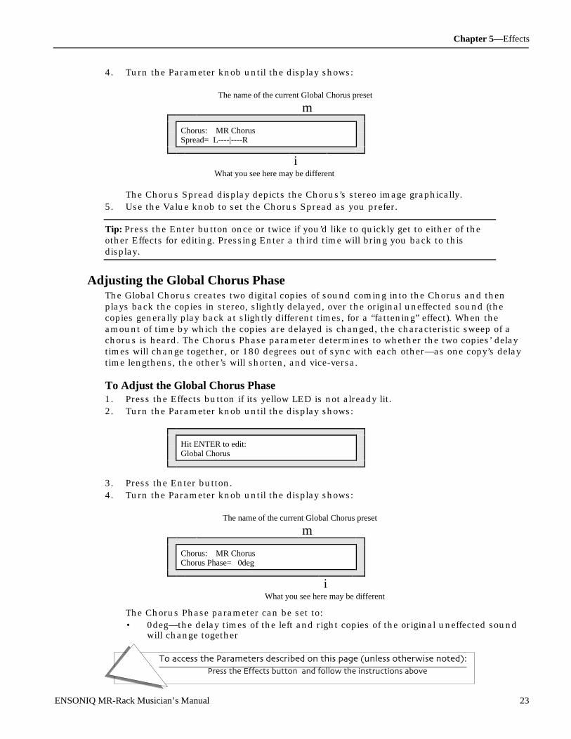
Chapter 5—Effects
To access the Parameters described on this page (unless otherwise noted):
Press the Effects button, and follow the instructions above.
ENSONIQ MR-Rack Musician’s Manual 23
4. Turn the Parameter knob until the display shows:
The name of the current Global Chorus preset
m
Chorus: MR ChorusSpread= L----|----R
iWhat you see here may be different
The Chorus Spread display depicts the Chorus’s stereo image graphically.5. Use the Value knob to set the Chorus Spread as you prefer.
Tip: Press the Enter button once or twice if you’d like to quickly get to either of theother Effects for editing. Pressing Enter a third time will bring you back to thisdisplay.
Adjusting the Global Chorus PhaseThe Global Chorus creates two digital copies of sound coming into the Chorus and thenplays back the copies in stereo, slightly delayed, over the original uneffected sound (thecopies generally play back at slightly different times, for a “fattening” effect). When theamount of time by which the copies are delayed is changed, the characteristic sweep of achorus is heard. The Chorus Phase parameter determines to whether the two copies’ delaytimes will change together, or 180 degrees out of sync with each other—as one copy’s delaytime lengthens, the other’s will shorten, and vice-versa.
To Adjust the Global Chorus Phase1. Press the Effects button if its yellow LED is not already lit.2. Turn the Parameter knob until the display shows:
Hit ENTER to edit:Global Chorus
3. Press the Enter button.4. Turn the Parameter knob until the display shows:
The name of the current Global Chorus preset
m
Chorus: MR ChorusChorus Phase= 0deg
iWhat you see here may be different
The Chorus Phase parameter can be set to:• 0deg—the delay times of the left and right copies of the original uneffected sound
will change together

Chapter 5—Effects
To access the Parameters described on this page (unless otherwise noted):
Press the Effects button, and follow the instructions above.
24 ENSONIQ MR-Rack Musician’s Manual
• -180deg—the delay times of the left and right copies of the original uneffectedsound will change 180 degrees out of sync with each other
5. Use the Value knob to set the Chorus Phase as you prefer.
Tip: Press the Enter button once or twice if you’d like to quickly get to either of theother Effects for editing. Pressing Enter a third time will bring you back to thisdisplay.
Determining Which MR-Rack Outputs the Global Chorus Will UseYou can route the Global Chorus to the MR-Rack’s rear-panel Main or Aux output jacks.This can be convenient for isolating Chorused Sounds to their own outputs.
To Set the Global Chorus’s Output Routing1. Press Enter.
If the Effect button’s red LED is lit or flashing, you may not be able to hear the GlobalChorus. See “Bypassing Effects” later in this chapter to learn about bypassing and un-bypassing Effects.
2. Turn the Parameter knob until the display shows:
Hit ENTER to edit:Output Assigns
3. Press Enter.4. Turn the Parameter knob until the display shows:
Output Assign forGlobal Chorus= Main
The output of the Global Chorus can be routed to:• Main—the output of the Global Chorus will be routed to the MR-Rack’s Main Outs• Aux—the output of the Global Chorus will be routed to the MR-Rack’s Aux Outs
5. Use the value knob to route the Global Chorus’s output to the MR-Rack’s rear-panelMain Outs or the Aux Outs.
Wor king wit h t he Global R e ve r bThe MR-Rack Global Reverb features a number of parameters that allow you to customize itto your idea of perfection. You can also route the Global Reverb to either the MR-Rack’srear-panel Main or Aux Outs. Global Reverb parameter values are saved with eachPerformance.
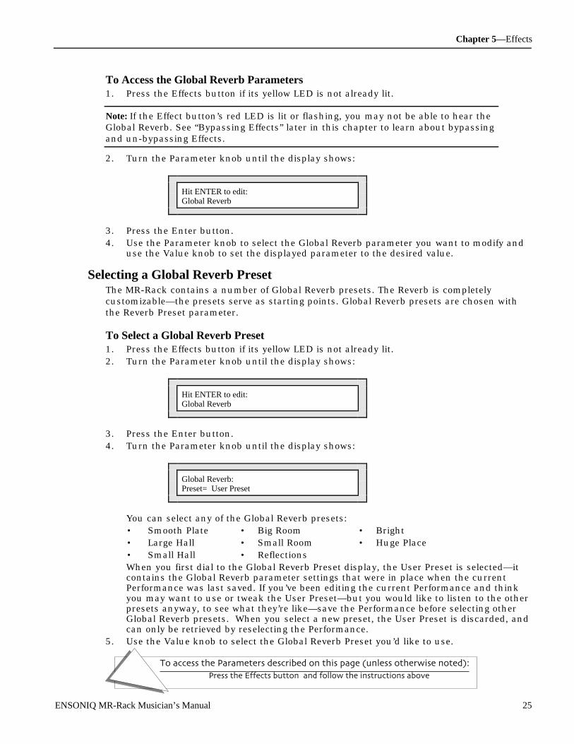
Chapter 5—Effects
To access the Parameters described on this page (unless otherwise noted):
Press the Effects button, and follow the instructions above.
ENSONIQ MR-Rack Musician’s Manual 25
To Access the Global Reverb Parameters1. Press the Effects button if its yellow LED is not already lit.
Note: If the Effect button’s red LED is lit or flashing, you may not be able to hear theGlobal Reverb. See “Bypassing Effects” later in this chapter to learn about bypassingand un-bypassing Effects.
2. Turn the Parameter knob until the display shows:
Hit ENTER to edit:Global Reverb
3. Press the Enter button.4. Use the Parameter knob to select the Global Reverb parameter you want to modify and
use the Value knob to set the displayed parameter to the desired value.
Selecting a Global Reverb PresetThe MR-Rack contains a number of Global Reverb presets. The Reverb is completelycustomizable—the presets serve as starting points. Global Reverb presets are chosen withthe Reverb Preset parameter.
To Select a Global Reverb Preset1. Press the Effects button if its yellow LED is not already lit.2. Turn the Parameter knob until the display shows:
Hit ENTER to edit:Global Reverb
3. Press the Enter button.4. Turn the Parameter knob until the display shows:
Global Reverb:Preset= User Preset
You can select any of the Global Reverb presets:• Smooth Plate • Big Room • Bright• Large Hall • Small Room • Huge Place• Small Hall • ReflectionsWhen you first dial to the Global Reverb Preset display, the User Preset is selected—itcontains the Global Reverb parameter settings that were in place when the currentPerformance was last saved. If you’ve been editing the current Performance and thinkyou may want to use or tweak the User Preset—but you would like to listen to the otherpresets anyway, to see what they’re like—save the Performance before selecting otherGlobal Reverb presets. When you select a new preset, the User Preset is discarded, andcan only be retrieved by reselecting the Performance.
5. Use the Value knob to select the Global Reverb Preset you’d like to use.

Chapter 5—Effects
To access the Parameters described on this page (unless otherwise noted):
Press the Effects button, and follow the instructions above.
26 ENSONIQ MR-Rack Musician’s Manual
Allow a moment for the MR-Rack to download the new Global Reverb Preset you’ve chosen.
Tip: Press the Enter button once or twice if you’d like to quickly get to either of theother Effects for editing. Pressing Enter a third time will bring you back to thisdisplay.
Setting Reverb Amounts for the Light, Medium and Wet Reverb BussesThere are three different amounts of Global Reverb available to the Parts—and theirSounds—in every Performance. While the overall volume of the Global Reverb Effect isdetermined by the setting of the Reverb Return Level parameter (described later in thischapter) the MR-Rack provides three separate and customizable busses for sendingParts—and their Sounds—into a Performance’s Global Reverb Effect:
• the LightReverb FX Bus—for sending minimal amounts of dry sound into the GlobalReverb
• the MediumReverb FX Bus—for sending average amounts of dry sound into the GlobalReverb
• the WetReverb FX Bus—for sending larger amounts of dry sound into the Global Reverb
The LightReverb, MediumReverb and WetReverb busses can each be set anywhere withintheir general ranges—their settings are saved with the Performance. The FX Bus Partparameter assigns Parts and their Sounds to whichever of these busses provides the desiredamount of Global Reverb (for details, see “Adding Effects to Part Sounds” in Chapter 4).
To Set the LightReverb Amount1. Press the Effects button if its yellow LED is not already lit.2. Turn the Parameter knob until the display shows:
Hit ENTER to edit:Global Reverb
3. Press the Enter button.4. Turn the Parameter knob until the display shows:
LightReverb FX Bus:GlobalReverb Amt= 43
iThe number you see here may be different
The LightReverb Global Reverb Amount can be set anywhere from 0 to 63.5. Use the Value knob to set the LightReverb Global Reverb Amount to the desired value.

Chapter 5—Effects
To access the Parameters described on this page (unless otherwise noted):
Press the Effects button, and follow the instructions above.
ENSONIQ MR-Rack Musician’s Manual 27
Tip: Press the Enter button once or twice if you’d like to quickly get to either of theother Effects for editing. Pressing Enter a third time will bring you back to thisdisplay.
To Set the MediumReverb Amount1. Press the Effects button if its yellow LED is not already lit.2. Turn the Parameter knob until the display shows:
Hit ENTER to edit:Global Reverb
3. Press the Enter button.4. Turn the Parameter knob until the display shows:
MediumReverb FX Bus:GlobalReverb Amt= 64
iThe number you see here may be different
The MediumReverb Global Reverb Amount can be set anywhere from 32 to 95.5. Use the Value knob to set the MediumReverb Global Reverb Amount to the desired
value.
Tip: Press the Enter button once or twice if you’d like to quickly get to either of theother Effects for editing. Pressing Enter a third time will bring you back to thisdisplay.
To Set the WetReverb Amount1. Press the Effects button if its yellow LED is not already lit.2. Turn the Parameter knob until the display shows:
Hit ENTER to edit:Global Reverb
3. Press the Enter button.4. Turn the Parameter knob until the display shows:
WetReverb FX Bus:GlobalReverb Amt= 99
iThe number you see here may be different
The WetReverb Global Reverb Amount can be set anywhere from 64 to 127.
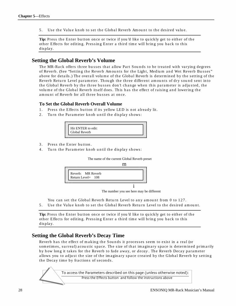
Chapter 5—Effects
To access the Parameters described on this page (unless otherwise noted):
Press the Effects button, and follow the instructions above.
28 ENSONIQ MR-Rack Musician’s Manual
5. Use the Value knob to set the Global Reverb Amount to the desired value.
Tip: Press the Enter button once or twice if you’d like to quickly get to either of theother Effects for editing. Pressing Enter a third time will bring you back to thisdisplay.
Setting the Global Reverb’s VolumeThe MR-Rack offers three busses that allow Part Sounds to be treated with varying degreesof Reverb. (See “Setting the Reverb Amounts for the Light, Medium and Wet Reverb Busses”above for details.) The overall volume of the Global Reverb is determined by the setting of theReverb Return Level parameter. Though the three different amounts of dry sound sent intothe Global Reverb by the three busses don’t change when this parameter is adjusted, thevolume of the Global Reverb itself does. This has the effect of raising and lowering theamount of Reverb for all three busses at once.
To Set the Global Reverb Overall Volume1. Press the Effects button if its yellow LED is not already lit.2. Turn the Parameter knob until the display shows:
Hit ENTER to edit:Global Reverb
3. Press the Enter button.4. Turn the Parameter knob until the display shows:
The name of the current Global Reverb preset
m
Reverb: MR ReverbReturn Level= 108
iThe number you see here may be different
You can set the Global Reverb Return Level to any amount from 0 to 127.5. Use the Value knob to set the Global Reverb Return Level to the desired amount.
Tip: Press the Enter button once or twice if you’d like to quickly get to either of theother Effects for editing. Pressing Enter a third time will bring you back to thisdisplay.
Setting the Global Reverb’s Decay TimeReverb has the effect of making the Sounds it processes seem to exist in a real (orsometimes, surreal) acoustic space. The size of that imaginary space is determined primarilyby how long it takes for the Reverb to fade away, or decay. The Reverb Decay parameterallows you to adjust the size of the imaginary space created by the Global Reverb by settingthe Decay time by fractions of seconds.

Chapter 5—Effects
To access the Parameters described on this page (unless otherwise noted):
Press the Effects button, and follow the instructions above.
ENSONIQ MR-Rack Musician’s Manual 29
To Set the Global Reverb’s Decay Time1. Press the Effects button if its yellow LED is not already lit.2. Turn the Parameter knob until the display shows:
Hit ENTER to edit:Global Reverb
3. Press the Enter button.4. Turn the Parameter knob until the display shows:
The name of the current Global Reverb preset
m
Reverb: MR ReverbDecay= 2.2sec
iThe number you see here may be different
You can set the Global Reverb Decay Time from 0.0 sec (seconds) to 10.0sec.5. Use the Value knob to set the Global Reverb Decay time to the desired length.
Tip: Press the Enter button once or twice if you’d like to quickly get to either of theother Effects for editing. Pressing Enter a third time will bring you back to thisdisplay.
Setting the Global Reverb’s High-Frequency DampingAs the Global Reverb decays, HF (for “High Frequency”) Damping progressively decreases thevolume of frequencies that occur above the value set with the Reverb HF Dampingparameter. By setting the damping to a higher frequency, the Global Reverb appears moreexpansive, since its high-frequency content doesn’t drop off before the Reverb fades away.Lower values suggest a somehow more contained space as the decay becomes muffled as itrings off.
To Set the Global Reverb’s HF Damping1. Press the Effects button if its yellow LED is not already lit.2. Turn the Parameter knob until the display shows:
Hit ENTER to edit:Global Reverb
3. Press the Enter button.4. Turn the Parameter knob until the display shows:
The name of the current Global Reverb preset
m

Chapter 5—Effects
To access the Parameters described on this page (unless otherwise noted):
Press the Effects button, and follow the instructions above.
30 ENSONIQ MR-Rack Musician’s Manual
Reverb: MR ReverbHF Damping= 10.2kHz
iThe number you see here may be different
You can set the Global Reverb High-Frequency Damping from 100 Hz to 21.2kHz.5. Use the Value knob to set the Global Reverb HF Damping to the desired frequency.
Tip: Press the Enter button once or twice if you’d like to quickly get to either of theother Effects for editing. Pressing Enter a third time will bring you back to thisdisplay.
Setting the Global Reverb’s BrightnessThe Global Reverb’s HF (for “High Frequency”) Bandwidth parameter filters out frequenciesthat occur above the HF Bandwidth parameter’s value. Set the HF Bandwidth to a higherfrequency to suggest hard reflective surfaces and lower values to imply softer surfaces .
To Set the Global Reverb’s HF Bandwidth1. Press the Effects button if its yellow LED is not already lit.2. Turn the Parameter knob until the display shows:
Hit ENTER to edit:Global Reverb
3. Press the Enter button.4. Turn the Parameter knob until the display shows:
The name of the current Global Reverb preset
m
Reverb: MR ReverbHF Bandwidth=14.2kHz
iThe number you see here may be different
You can set the Global Reverb High-Frequency Bandwidth from 100 Hz to 21.2kHz.5. Use the Value knob to set the Global Reverb HF Bandwidth to the desired frequency.
Tip: Press the Enter button once or twice if you’d like to quickly get to either of theother Effects for editing. Pressing Enter a third time will bring you back to thisdisplay.
Setting the Global Reverb’s DiffusionQuick, unusually loud bursts of sound—transients—may need some help to blend inpleasingly with the rest of the Global Reverb. The Reverb Diffusion 1 and 2 parameters offer
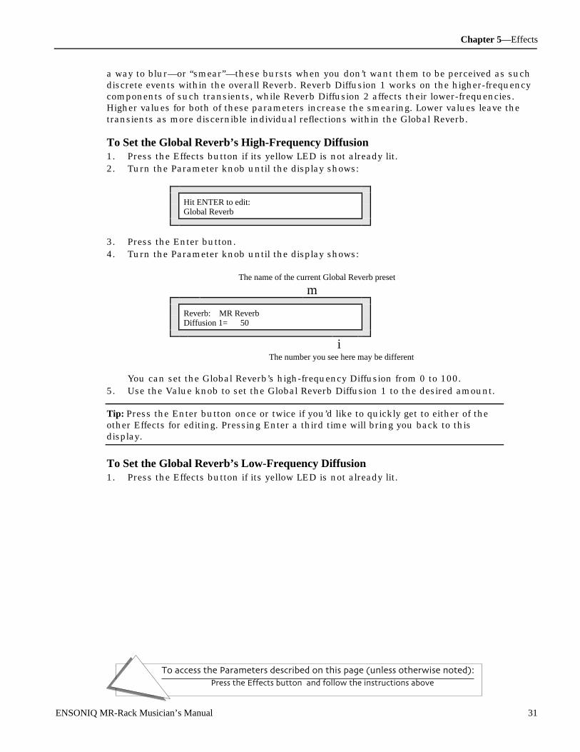
Chapter 5—Effects
To access the Parameters described on this page (unless otherwise noted):
Press the Effects button, and follow the instructions above.
ENSONIQ MR-Rack Musician’s Manual 31
a way to blur—or “smear”—these bursts when you don’t want them to be perceived as suchdiscrete events within the overall Reverb. Reverb Diffusion 1 works on the higher-frequencycomponents of such transients, while Reverb Diffusion 2 affects their lower-frequencies.Higher values for both of these parameters increase the smearing. Lower values leave thetransients as more discernible individual reflections within the Global Reverb.
To Set the Global Reverb’s High-Frequency Diffusion1. Press the Effects button if its yellow LED is not already lit.2. Turn the Parameter knob until the display shows:
Hit ENTER to edit:Global Reverb
3. Press the Enter button.4. Turn the Parameter knob until the display shows:
The name of the current Global Reverb preset
m
Reverb: MR ReverbDiffusion 1= 50
iThe number you see here may be different
You can set the Global Reverb’s high-frequency Diffusion from 0 to 100.5. Use the Value knob to set the Global Reverb Diffusion 1 to the desired amount.
Tip: Press the Enter button once or twice if you’d like to quickly get to either of theother Effects for editing. Pressing Enter a third time will bring you back to thisdisplay.
To Set the Global Reverb’s Low-Frequency Diffusion1. Press the Effects button if its yellow LED is not already lit.

Chapter 5—Effects
To access the Parameters described on this page (unless otherwise noted):
Press the Effects button, and follow the instructions above.
32 ENSONIQ MR-Rack Musician’s Manual
2. Turn the Parameter knob until the display shows:
Hit ENTER to edit:Global Reverb
3. Press the Enter button.4. Turn the Parameter knob until the display shows:
The name of the current Global Reverb preset
m
Reverb: MR ReverbDiffusion 2= 50
iThe number you see here may be different
You can set the Global Reverb’s low-frequency Diffusion from 0 to 100.5. Use the Value knob to set the Global Reverb Diffusion 2 to the desired amount.
Tip: Press the Enter button once or twice if you’d like to quickly get to either of theother Effects for editing. Pressing Enter a third time will bring you back to thisdisplay.
Setting the Global Reverb’s DefinitionReverb is achieved by creating many copies of an uneffected signal and playing back thosecopies one after the other, too close together in time to be perceived as separate copies, anddecreasing in volume until silence is reached. As the copies fade away, they may occurcloser together in time, acquiring a greater density. The Reverb Definition parameter allowsyou to adjust how quickly this density will increase as the Global Reverb decays. Highervalues cause the Global Reverb to “thicken” as it trails off. Lower values leave it with a moreconsistent sound as it fades away.
To Set the Global Reverb’s Definition1. Press the Effects button if its yellow LED is not already lit.2. Turn the Parameter knob until the display shows:
Hit ENTER to edit:Global Reverb
3. Press the Enter button.
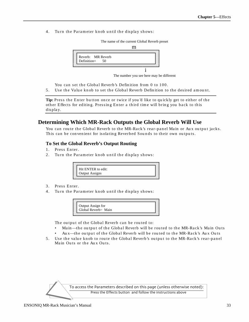
Chapter 5—Effects
To access the Parameters described on this page (unless otherwise noted):
Press the Effects button, and follow the instructions above.
ENSONIQ MR-Rack Musician’s Manual 33
4. Turn the Parameter knob until the display shows:
The name of the current Global Reverb preset
m
Reverb: MR ReverbDefinition= 50
iThe number you see here may be different
You can set the Global Reverb’s Definition from 0 to 100.5. Use the Value knob to set the Global Reverb Definition to the desired amount.
Tip: Press the Enter button once or twice if you’d like to quickly get to either of theother Effects for editing. Pressing Enter a third time will bring you back to thisdisplay.
Determining Which MR-Rack Outputs the Global Reverb Will UseYou can route the Global Reverb to the MR-Rack’s rear-panel Main or Aux output jacks.This can be convenient for isolating Reverbed Sounds to their own outputs.
To Set the Global Reverb’s Output Routing1. Press Enter.2. Turn the Parameter knob until the display shows:
Hit ENTER to edit:Output Assigns
3. Press Enter.4. Turn the Parameter knob until the display shows:
Output Assign forGlobal Reverb= Main
The output of the Global Reverb can be routed to:• Main—the output of the Global Reverb will be routed to the MR-Rack’s Main Outs• Aux—the output of the Global Reverb will be routed to the MR-Rack’s Aux Outs
5. Use the value knob to route the Global Reverb’s output to the MR-Rack’s rear-panelMain Outs or the Aux Outs.

Chapter 5—Effects
To access the Parameters described on this page (unless otherwise noted):
Press the Effects button, and follow the instructions above.
34 ENSONIQ MR-Rack Musician’s Manual
Wor king wit h D r y SoundsMR-Rack Parts and their Sounds don’t have to use the MR-Rack Effects—they can beassigned to the Dry bus (see “Understanding Effects Busses” above). The Dry bus can berouted to either the MR-Rack’s Main or Aux Outs.
To Set the Dry Bus’s Output Routing1. Press Enter.2. Turn the Parameter knob until the display shows:
Hit ENTER to edit:Output Assigns
3. Press Enter.4. Turn the Parameter knob until the display shows:
Output Assign forDry FX Bus= Main
The output of the Dry Effect bus can be routed to:• Main—the output of the Dry Effect bus will be routed to the MR-Rack’s Main Outs• Aux—the output of the Dry Effect bus will be routed to the MR-Rack’s Aux Outs
5. Use the value knob to route the Dry Effect bus’s output to the MR-Rack’s rear-panelMain Outs or the Aux Outs.
Bypassing Ef f e c t sThere may be times when you’d like to temporarily turn an Effect—or all of the Effects—offin order to hear the Sounds you’re using them on in their uneffected, “dry,” state. This isaccomplished by bypassing the Effects. You can bypass an individual Effect, pairs of themor all of them at once. The MR-Rack provides a number of ways to bypass Effects, so thatit’s easy to do no matter what you’re currently doing with the MR-Rack. Some bypassmethods use the Effects button, some use the Effects Bypass parameter, and one uses both.
Note: When the Insert Effects is bypassed, it still responds to real-time modulationvia MIDI. Any real-time changes made by that modulation while the Effect isbypassed will be heard when it’s un-bypassed.
The Effect button’s red LED tells you at a glance whether any or all of the Effects arebypassed:
• If the Effect button’s red LED is not lit, none of the Effects are bypassed.• If the Effect button’s red LED is lit and not flashing, one or two of the Effects are
bypassed and won’t be heard. (See “Learning Which Effects Are Bypassed” below tolearn how to tell which Effect or Effects are turned off.)
• If the Effect button’s red LED is flashing, all of the Effects are bypassed and won’t beheard.

Chapter 5—Effects
To access the Parameters described on this page (unless otherwise noted):
Press the Effects button, and follow the instructions above.
ENSONIQ MR-Rack Musician’s Manual 35
Bypassing and Un-Bypassing With the Effects ButtonYou can use the Effects button as a convenient bypass/un-bypass toggle switch.
To Bypass an Individual Effect Using the Effects ButtonIn order to bypass one of the Effects using the Effects button, the MR-Rack’s display mustshow:
Hit ENTER to edit: an Effect
iThis should be the name of the Effect you want to bypass
You can get to this display easily, regardless of where in the MR-Rack you are when youdecide to bypass an Effect. One of these scenarios should apply to you:
• If you’re not currently working on the Effects, press the Effects button so that its yellowLED lights. Turn the Parameter knob to dial in the version of the display above thatshows the Effect you want to bypass.
• If you’ve just begun to work on the Effects—and its yellow LED is lit—but haven’t yet hitEnter to start editing the Insert Effect, Global Chorus or Global Reverb parameters,turn the Parameter knob to dial in the version of the display above that shows the Effectyou want to bypass.
• If you’re currently editing the Insert Control Part or Bypass parameter—and the Effectbutton’s yellow LED is lit—turn the Parameter knob to dial in the version of the displayabove that shows the Effect you want to bypass.
• If you’re currently editing the Insert Effect, Global Chorus or Global Reverb parameters,press the Effect button and then turn the Parameter knob to dial in the version of thedisplay above that shows the Effect you want to bypass.
Once the “Hit ENTER to edit:” display appears, and the Effect you want to bypass is showingon its bottom line:
1. Press the Effects button.The Effects button’s red LED will light and the display will show:
Hit ENTER to edit: an Effect *BYPD*
i*BYPD* tells you the Effect is bypassed
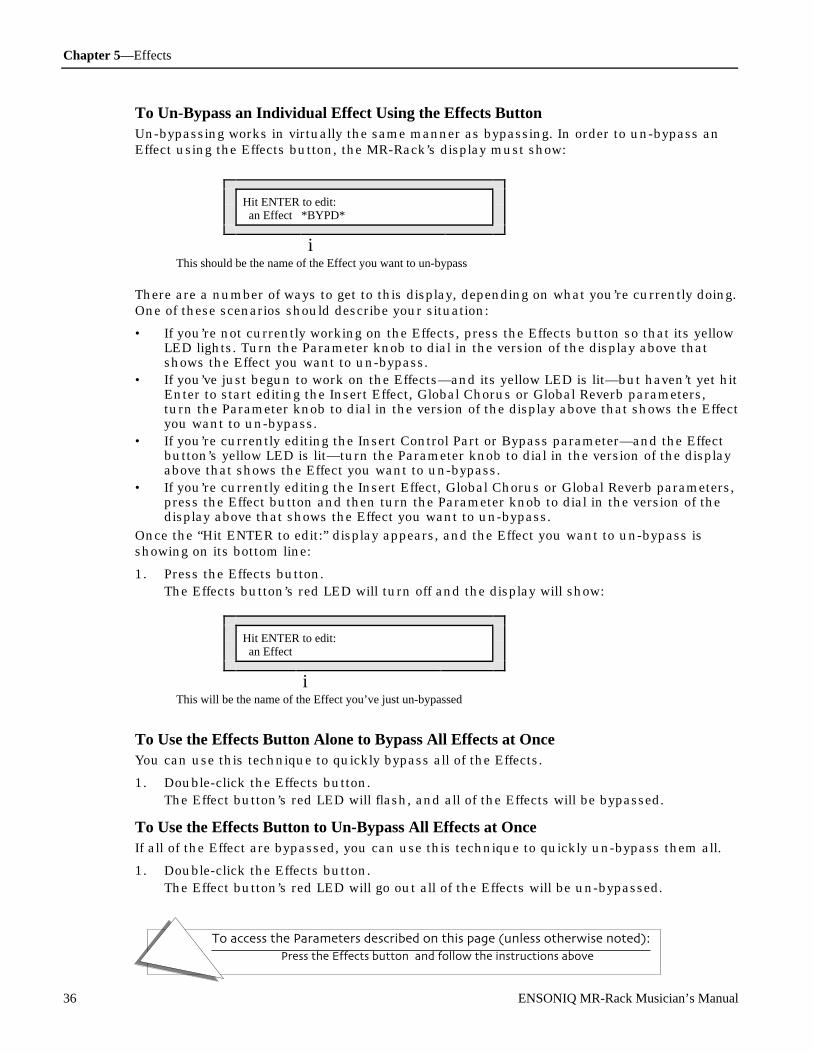
Chapter 5—Effects
To access the Parameters described on this page (unless otherwise noted):
Press the Effects button, and follow the instructions above.
36 ENSONIQ MR-Rack Musician’s Manual
To Un-Bypass an Individual Effect Using the Effects ButtonUn-bypassing works in virtually the same manner as bypassing. In order to un-bypass anEffect using the Effects button, the MR-Rack’s display must show:
Hit ENTER to edit: an Effect *BYPD*
iThis should be the name of the Effect you want to un-bypass
There are a number of ways to get to this display, depending on what you’re currently doing.One of these scenarios should describe your situation:
• If you’re not currently working on the Effects, press the Effects button so that its yellowLED lights. Turn the Parameter knob to dial in the version of the display above thatshows the Effect you want to un-bypass.
• If you’ve just begun to work on the Effects—and its yellow LED is lit—but haven’t yet hitEnter to start editing the Insert Effect, Global Chorus or Global Reverb parameters,turn the Parameter knob to dial in the version of the display above that shows the Effectyou want to un-bypass.
• If you’re currently editing the Insert Control Part or Bypass parameter—and the Effectbutton’s yellow LED is lit—turn the Parameter knob to dial in the version of the displayabove that shows the Effect you want to un-bypass.
• If you’re currently editing the Insert Effect, Global Chorus or Global Reverb parameters,press the Effect button and then turn the Parameter knob to dial in the version of thedisplay above that shows the Effect you want to un-bypass.
Once the “Hit ENTER to edit:” display appears, and the Effect you want to un-bypass isshowing on its bottom line:
1. Press the Effects button.The Effects button’s red LED will turn off and the display will show:
Hit ENTER to edit: an Effect
iThis will be the name of the Effect you’ve just un-bypassed
To Use the Effects Button Alone to Bypass All Effects at OnceYou can use this technique to quickly bypass all of the Effects.
1. Double-click the Effects button.The Effect button’s red LED will flash, and all of the Effects will be bypassed.
To Use the Effects Button to Un-Bypass All Effects at OnceIf all of the Effect are bypassed, you can use this technique to quickly un-bypass them all.
1. Double-click the Effects button.The Effect button’s red LED will go out all of the Effects will be un-bypassed.
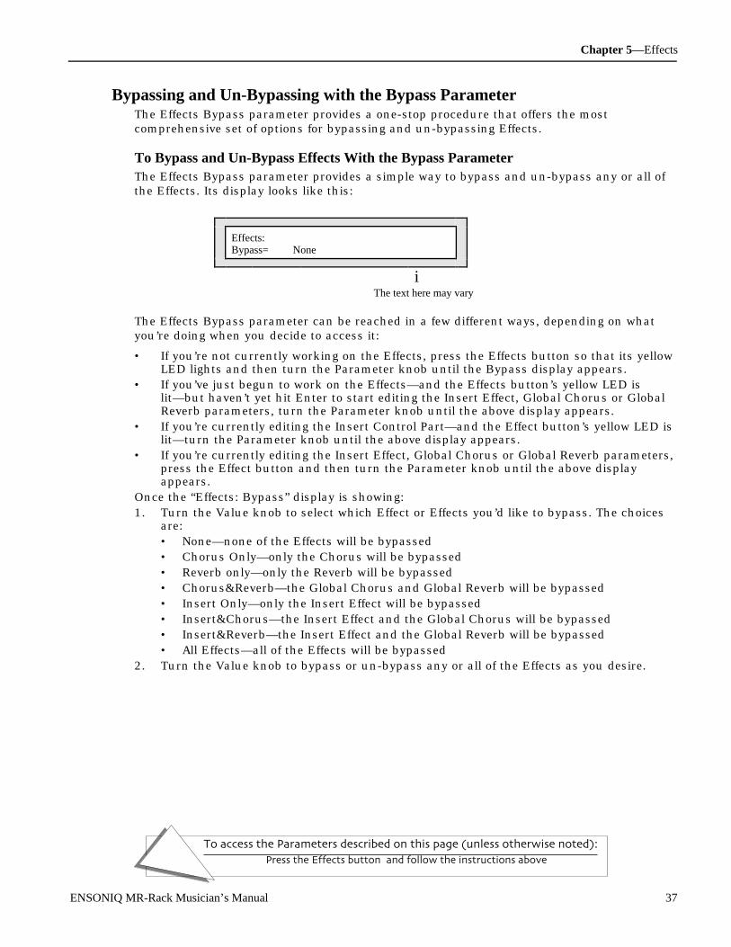
Chapter 5—Effects
To access the Parameters described on this page (unless otherwise noted):
Press the Effects button, and follow the instructions above.
ENSONIQ MR-Rack Musician’s Manual 37
Bypassing and Un-Bypassing with the Bypass ParameterThe Effects Bypass parameter provides a one-stop procedure that offers the mostcomprehensive set of options for bypassing and un-bypassing Effects.
To Bypass and Un-Bypass Effects With the Bypass ParameterThe Effects Bypass parameter provides a simple way to bypass and un-bypass any or all ofthe Effects. Its display looks like this:
Effects:Bypass= None
iThe text here may vary
The Effects Bypass parameter can be reached in a few different ways, depending on whatyou’re doing when you decide to access it:
• If you’re not currently working on the Effects, press the Effects button so that its yellowLED lights and then turn the Parameter knob until the Bypass display appears.
• If you’ve just begun to work on the Effects—and the Effects button’s yellow LED islit—but haven’t yet hit Enter to start editing the Insert Effect, Global Chorus or GlobalReverb parameters, turn the Parameter knob until the above display appears.
• If you’re currently editing the Insert Control Part—and the Effect button’s yellow LED islit—turn the Parameter knob until the above display appears.
• If you’re currently editing the Insert Effect, Global Chorus or Global Reverb parameters,press the Effect button and then turn the Parameter knob until the above displayappears.
Once the “Effects: Bypass” display is showing:1. Turn the Value knob to select which Effect or Effects you’d like to bypass. The choices
are:• None—none of the Effects will be bypassed• Chorus Only—only the Chorus will be bypassed• Reverb only—only the Reverb will be bypassed• Chorus&Reverb—the Global Chorus and Global Reverb will be bypassed• Insert Only—only the Insert Effect will be bypassed• Insert&Chorus—the Insert Effect and the Global Chorus will be bypassed• Insert&Reverb—the Insert Effect and the Global Reverb will be bypassed• All Effects—all of the Effects will be bypassed
2. Turn the Value knob to bypass or un-bypass any or all of the Effects as you desire.

Chapter 5—Effects
To access the Parameters described on this page (unless otherwise noted):
Press the Effects button, and follow the instructions above.
38 ENSONIQ MR-Rack Musician’s Manual
Quick Bypass of All Effects with the Bypass ParameterYou can press the Effect button once to quickly bypass or un-bypass all of the Effects atonce while you’re viewing the Effects Bypass parameter display:
Effects:Bypass= None
iThe text here may vary
• If none of the Effects are currently bypassed as you view the Effects Bypass parameterdisplay, press the Effects button once to bypass them all.
• If any of the Effects are currently bypassed as you view the Effects Bypass parameterdisplay, press the Effects button once to un-bypass them all.
Learning Which Effects are Bypassed When the Red Effects LED Is LitIf the Effects button’s red LED is lit—and not flashing—one or two Effects are bypassed. Ifit’s flashing, all of the Effects are bypassed.
To Easily Find Out Which Effects are BypassedThe Effects Bypass parameter’s display can quickly tell you which Effect or Effects arebypassed.
Effects:Bypass= Chorus Only
iThis area of the display shows which Effect or Effects are currently bypassed
The Effects Bypass parameter can be reached in a few different ways, depending on whatyou’re doing when you decide to access it:
• If you’re not currently working on the Effects, press the Effects button so that its yellowLED lights and then turn the Parameter knob until the Bypass display appears.
• If you’ve just begun to work on the Effects—and the Effects button’s yellow LED islit—but haven’t yet hit Enter to start editing the Insert Effect, Global Chorus or GlobalReverb parameters, turn the Parameter knob until the above display appears.
• If you’re currently editing the Insert Control Part—and the Effect button’s yellow LED islit—turn the Parameter knob until the above display appears.
• If you’re currently editing the Insert Effect, Global Chorus or Global Reverb parameters,press the Effect button and then turn the Parameter knob until the above displayappears.
The Effects Bypass parameter can be adjusted, if you like, to change which Effect or Effectsare bypassed.

Chapter 6—Special Commands
To access the Parameters described on this page (unless otherwise noted):Press the Save button, turn the Parameter knob to locate the action, and
then turn the Value knob to select the object of the action.
ENSONIQ MR-Rack Musician’s Manual 1
Ch apt e r 6Sp ec i al C om m ands
This chapter describes some of the special processes the MR-Rack can perform. Once you’vestarted customizing the MR-Rack’s Sounds and Performances, you’ll probably want to saveyour work. This chapter will teach you how to save, copy, and store MR-Rack information tointernal RAM memory, MIDI storage devices, and to PCMCIA SRAM memory cards, whichyou’ll learn how to prepare for storage.
To access the functions in this chapter, press the Save button, except where noted.
All Notes OffAudition
MIDI Save
Data CardPower
Each of the functions described in this chapter are invoked with a command.
To select a command, turn the Parameters knob. To select the object of the command, turnthe Value knob.
Parameter Value
The Four Spe c ial Comm an dsPressing the Save button displays and allows four commands:
• Save—to store a selected object in any writable, non-ROM, location• Dump—transmits the selected object as MIDI SysEx data that can be stored in any
external MIDI storage device capable of receiving SysEx dumps• Copy—copies entire Sound and Performance banks between writable memory locations• Init—clears sound and memory locations in preparation for new data
To Abort a CommandThe Exit button is used to abort the current command and displays the Sound page.
Note: Only RAM and non-write-protected card locations are visible as writable targetdestinations.

Chapter 6—Special Commands
To access the Parameters described on this page (unless otherwise noted):Press the Save button, turn the Parameter knob to locate the action, and
then turn the Value knob to select the object of the action.
2 ENSONIQ MR-Rack Musician’s Manual
Saving Com m ands
Saving the Current PerformanceThis command is used to save the currently selected Performance to any writablePerformance location.
To Save the Current Performance1. Press the Performance button and select the Performance that you want to save.2. Press the Save button.3. Turn the Parameter knob all the way counter clockwise.4. Turn the Value knob all the way counterclockwise. The display shows:
Hit ENTER to:Save:ThisPerformance
5. Press the Enter button.If the System Write Protect parameter is set to Prompt, the display will show:
System Write ProtectOn! ENTER Overrides.
This display is offered as a double-check for you to make sure you really want to savethis Performance. If you’d like to avoid this prompt in the future, see “Protecting theMR-Rack’s Memory” in Chapter 3.
6. If you’d like to cancel the operation, press the Exit button. If you’d like to proceed, pressthe Enter button. The display now allows you to name your Performance:
Left knob function Right knob function
m m
LEFT:pos RIGHT:charNew Name=InitPerform
iNew Performance Name
The Parameter knob (left) is used to select the character position within the name. Youwill know which character is selected because the position in the display will beunderlined. Turning the knob clockwise moves the location to the right, andcounterclockwise moves it to the left. The Value knob (right) is used to select the alpha-numeric character for that location.
7. Use the Parameter and Value knobs to select a name for your Performance.8. When you’ve named your Performance, press the Enter button.9. Use the Parameter knob to select either:
• RAM—to save the Performance to the MR-Rack’s internal RAM memory.• CRD—to save the Performance to an installed data card (see “Formatting a PCMCIA
Card” below for instructions on how to prepare a data card for storage).
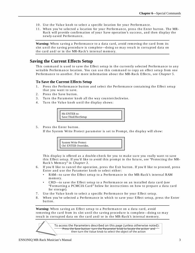
Chapter 6—Special Commands
To access the Parameters described on this page (unless otherwise noted):Press the Save button, turn the Parameter knob to locate the action, and
then turn the Value knob to select the object of the action.
ENSONIQ MR-Rack Musician’s Manual 3
10. Use the Value knob to select a specific location for your Performance.11. When you’ve selected a location for your Performance, press the Enter button. The MR-
Rack will provide confirmation of your Save operation’s success, and then display thenewly-saved Performance.
Warning: When saving a Performance to a data card, avoid removing the card from itsslot until the saving procedure is complete—doing so may result in corrupted data onthe card and/or in the MR-Rack’s internal memory.
Saving the Current Effects SetupThis command is used to save the Effect setup in the currently selected Performance to anywritable Performance location. You can use this command to copy an effect setup from onePerformance to another. For more information about the MR-Rack Effects, see Chapter 5.
To Save the Current Effects Setup1. Press the Performance button and select the Performance containing the Effect setup
that you want to save.2. Press the Save button.3. Turn the Parameter knob all the way counterclockwise.4. Turn the Value knob until the display shows:
Hit ENTER to:Save:ThisEffectSetup
5. Press the Enter button.If the System Write Protect parameter is set to Prompt, the display will show:
System Write ProtectOn! ENTER Overrides.
This display is offered as a double-check for you to make sure you really want to savethis Effect setup. If you’d like to avoid this prompt in the future, see “Protecting the MR-Rack’s Memory” in Chapter 3.
6. If you’d like to cancel the operation, press the Exit button. If you’d like to proceed, pressEnter and use the Parameter knob to select either:• RAM—to save the Effect setup to a Performance in the MR-Rack’s internal RAM
memory.• CRD—to save the Effect setup to a Performance on an installed data card (see
“Formatting a PCMCIA Card” below for instructions on how to prepare a data cardfor storage).
7. Use the Value knob to select a specific Performance for your Effect setup.8. When you’ve selected a Performance in which to save your Effect setup, press the Enter
button.
Warning: When saving an Effect setup to a Performance on a data card, avoidremoving the card from its slot until the saving procedure is complete—doing so mayresult in corrupted data on the card and/or in the MR-Rack’s internal memory.

Chapter 6—Special Commands
To access the Parameters described on this page (unless otherwise noted):Press the Save button, turn the Parameter knob to locate the action, and
then turn the Value knob to select the object of the action.
4 ENSONIQ MR-Rack Musician’s Manual
Saving the Current PerfEditKitThis command is used to save the PerfEditKit in the currently selected Performance to anywritable Performance location. For more information about using, creating, and editingDrum Kit Sounds, see Chapter 4.
To Save the Current PerfEditKit1. Press the Performance button and select the Performance that contains the PerfEditKit
that you want to save.2. Press the Save button.3. Turn the Parameter knob all the way counter clockwise.4. Turn the Value knob until the display shows:
Hit ENTER to:Save:ThisPerfEditKit
5. Press the Enter button.If the System Write Protect parameter is set to Prompt, the display will show:
System Write ProtectOn! ENTER Overrides.
This display is offered as a double-check for you to make sure you really want to savethis PerfEditKit. If you’d like to avoid this prompt in the future, see “Protecting the MR-Rack’s Memory” in Chapter 3.
6. If you’d like to cancel the operation, press the Exit button. If you’d like to proceed, pressEnter and use the Parameter knob to select either:• RAM—to save the PerfEditKit to a Performance in the MR-Rack’s internal RAM
memory.• CRD—to save the PerfEditKit to a Performance on an installed data card (see
“Formatting a PCMCIA Card” below for instructions on how to prepare a data cardfor storage).
7. Use the Value knob to select a specific Performance for your PerfEditKit.8. When you’ve selected a Performance in which to save your PerfEditKit, press the Enter
button.
Warning: When saving a PerfEditKit to a Performance on a data card, avoid removingthe card from its slot until the saving procedure is complete—doing so may result incorrupted data on the card and/or in the MR-Rack’s internal memory.

Chapter 6—Special Commands
To access the Parameters described on this page (unless otherwise noted):Press the Save button, turn the Parameter knob to locate the action, and
then turn the Value knob to select the object of the action.
ENSONIQ MR-Rack Musician’s Manual 5
Saving the Current Part’s SoundThis command is used to save the Sound on the currently selected Part to any writableSound location. If the PerfEditKit is on the currently selected Part, it will be copied out into aSound location, with a type of CUSTOM, and can be renamed.
When a Part’s Sound is saved, all of the current Sound-related Part settings are savedwithin the Sound:
• Part Volume • LFO Delay Time• Expression (Mix) • Amp Env Attack• Part Pan • Amp Env Decay• FX Bus • Amp Env Release• Pitch Bend Up • Filter Cutoff• Pitch Bend Down • Filt Env Attack• Octave Shift • Filt Env Decay• Semitone Shift • Filt Env Release• Fine Tuning • Amp&Filt Env Vel• PitchTbl • Key Range Lo• Glide Mode • Key Range Hi• Glide Time • VelocityRange Lo• Delay Offset • VelocityRange Hi• SyncLFO&Noise • VelocityMode• Normal LFO Rates • PressureMode• LFO Depth
(The Vol/MixPolarity parameter and the various MIDI reception filter parameters are notsaved with the Part’s Sound, since they affect the behavior of the Part itself, and have noimpact on the Sound.)
Note: After a Part’s Sound has been saved, the Parts parameters are reset to theirnominal values—the Sound has internalized the previous Part settings.
When the Sound being saved is on the Insert Control Part and is assigned to the Insert FXBus, the current Insert Effect will be saved in the Sound. If it’s assigned to another FX Bus,only its routing will be saved with the Sound.
When the Part’s Sound is a Drum Kit Sound, and any DrumKey is routed to the Insert FXBus, the Insert Effect will be saved with the Sound. (There’s an exception to this rule: whenthe only DrumKeys routed to the Insert FX Bus are using the Sound called “Silence,” theInsert Effect won’t be saved with the Sound.) The FX Bus routing of a Drum Kit’s DrumKeysis always saved, regardless of whether or not any non-Silence DrumKeys are assigned to theInsert FX Bus.
To Save the Current Part’s Sound1. Press the Sound button, and use the Select Part buttons to find the Sound that you
want to save.2. Press the Save button.3. Turn the Parameter knob all the way counterclockwise.

Chapter 6—Special Commands
To access the Parameters described on this page (unless otherwise noted):Press the Save button, turn the Parameter knob to locate the action, and
then turn the Value knob to select the object of the action.
6 ENSONIQ MR-Rack Musician’s Manual
4. Turn the Value knob until the display shows:
Hit ENTER to:Save:ThisPart’ sSound
5. Press the Enter button.If the System Write Protect parameter is set to Prompt, the display will show:
System Write ProtectOn! ENTER Overrides.
This display is offered as a double-check for you to make sure you really want to savethis Sound. If you’d like to avoid this prompt in the future, see “Protecting the MR-Rack’s Memory” in Chapter 3.
6. If you’d like to cancel the operation, press the Exit button. If you’d like to proceed, pressthe Enter button. The display now allows you to name your Sound:
Left knob function Right knob function
m m
LEFT:pos RIGHT:charNew Name=MySoundName
iNew Sound Name
The Parameter knob (left) is used to select the character position within the name. Youwill know which character is selected because the position in the display will beunderlined. Turning the knob clockwise moves the location to the right, andcounterclockwise moves it to the left. The Value knob (right) is used to select the alpha-numeric character for that location.
7. Use the Parameter and Value knobs to select a name for your Sound.8. When you’ve named your Sound, press the Enter button.9. Use the Value knob to select a SoundFinder type for your Sound. This feature allows
you to easily locate similar Sounds. For more information about using SoundFinder, seeChapter 1. For a complete list of SoundFinder types, see Chapter 9.
10. When you’ve defined a SoundFinder type, press the Enter button.11. Use the Parameter knob to select either:
• RAM—to save the Sound to the MR-Rack’s internal RAM memory.• CRD—to save the Sound to an installed data card (see “Formatting a PCMCIA Card”
below for instructions on how to prepare a data card for storage).12. Use the Value knob to select a specific location for your Sound.13. When you’ve selected a location for your Sound, press the Enter button. The display
momentarily confirms the successful completion of your command, and selects thenewly-saved Sound. All of the Part’s Sound-related parameters are reset to theirnominal values.
Warning: When saving a Sound to a data card, avoid removing the card from its slotuntil the saving procedure is complete—doing so may result in corrupted data on the
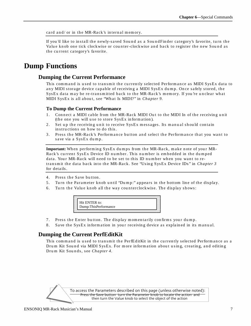
Chapter 6—Special Commands
To access the Parameters described on this page (unless otherwise noted):Press the Save button, turn the Parameter knob to locate the action, and
then turn the Value knob to select the object of the action.
ENSONIQ MR-Rack Musician’s Manual 7
card and/or in the MR-Rack’s internal memory.
If you’d like to install the newly-saved Sound as a SoundFinder category’s favorite, turn theValue knob one tick clockwise or counter-clockwise and back to register the new Sound asthe current category’s favorite.
D um p Func t ions
Dumping the Current PerformanceThis command is used to transmit the currently selected Performance as MIDI SysEx data toany MIDI storage device capable of receiving a MIDI SysEx dump. Once safely stored, theSysEx data may be re-transmitted back to the MR-Rack’s memory. If you’re unclear whatMIDI SysEx is all about, see “What Is MIDI?” in Chapter 9.
To Dump the Current Performance1. Connect a MIDI cable from the MR-Rack MIDI Out to the MIDI In of the receiving unit
(the one you will use to store SysEx information).2. Set up the receiving unit to receive SysEx messages. Its manual should contain
instructions on how to do this.3. Press the MR-Rack’s Performance button and select the Performance that you want to
save via a SysEx dump.
Important: When performing SysEx dumps from the MR-Rack, make note of your MR-Rack’s current SysEx Device ID number. This number is embedded in the dumpeddata. Your MR-Rack will need to be set to this ID number when you want to re-transmit the data back into the MR-Rack. See “Using SysEx Device IDs” in Chapter 3for details.
4. Press the Save button.5. Turn the Parameter knob until “Dump:” appears in the bottom line of the display.6. Turn the Value knob all the way counterclockwise. The display shows:
Hit ENTER to:Dump:ThisPerformance
7. Press the Enter button. The display momentarily confirms your dump.8. Save the SysEx information in your receiving device as explained in its manual.
Dumping the Current PerfEditKitThis command is used to transmit the PerfEditKit in the currently selected Performance as aDrum Kit Sound via MIDI SysEx. For more information about using, creating, and editingDrum Kit Sounds, see Chapter 4.
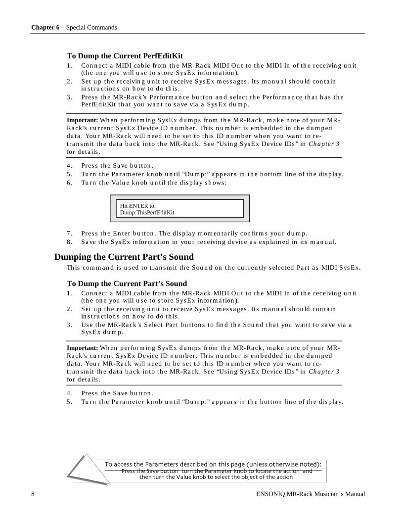
Chapter 6—Special Commands
To access the Parameters described on this page (unless otherwise noted):Press the Save button, turn the Parameter knob to locate the action, and
then turn the Value knob to select the object of the action.
8 ENSONIQ MR-Rack Musician’s Manual
To Dump the Current PerfEditKit1. Connect a MIDI cable from the MR-Rack MIDI Out to the MIDI In of the receiving unit
(the one you will use to store SysEx information).2. Set up the receiving unit to receive SysEx messages. Its manual should contain
instructions on how to do this.3. Press the MR-Rack’s Performance button and select the Performance that has the
PerfEditKit that you want to save via a SysEx dump.
Important: When performing SysEx dumps from the MR-Rack, make note of your MR-Rack’s current SysEx Device ID number. This number is embedded in the dumpeddata. Your MR-Rack will need to be set to this ID number when you want to re-transmit the data back into the MR-Rack. See “Using SysEx Device IDs” in Chapter 3for details.
4. Press the Save button.5. Turn the Parameter knob until “Dump:” appears in the bottom line of the display.6. Turn the Value knob until the display shows:
Hit ENTER to:Dump:ThisPerfEditKit
7. Press the Enter button. The display momentarily confirms your dump.8. Save the SysEx information in your receiving device as explained in its manual.
Dumping the Current Part’s SoundThis command is used to transmit the Sound on the currently selected Part as MIDI SysEx.
To Dump the Current Part’s Sound1. Connect a MIDI cable from the MR-Rack MIDI Out to the MIDI In of the receiving unit
(the one you will use to store SysEx information).2. Set up the receiving unit to receive SysEx messages. Its manual should contain
instructions on how to do this.3. Use the MR-Rack’s Select Part buttons to find the Sound that you want to save via a
SysEx dump.
Important: When performing SysEx dumps from the MR-Rack, make note of your MR-Rack’s current SysEx Device ID number. This number is embedded in the dumpeddata. Your MR-Rack will need to be set to this ID number when you want to re-transmit the data back into the MR-Rack. See “Using SysEx Device IDs” in Chapter 3for details.
4. Press the Save button.5. Turn the Parameter knob until “Dump:” appears in the bottom line of the display.
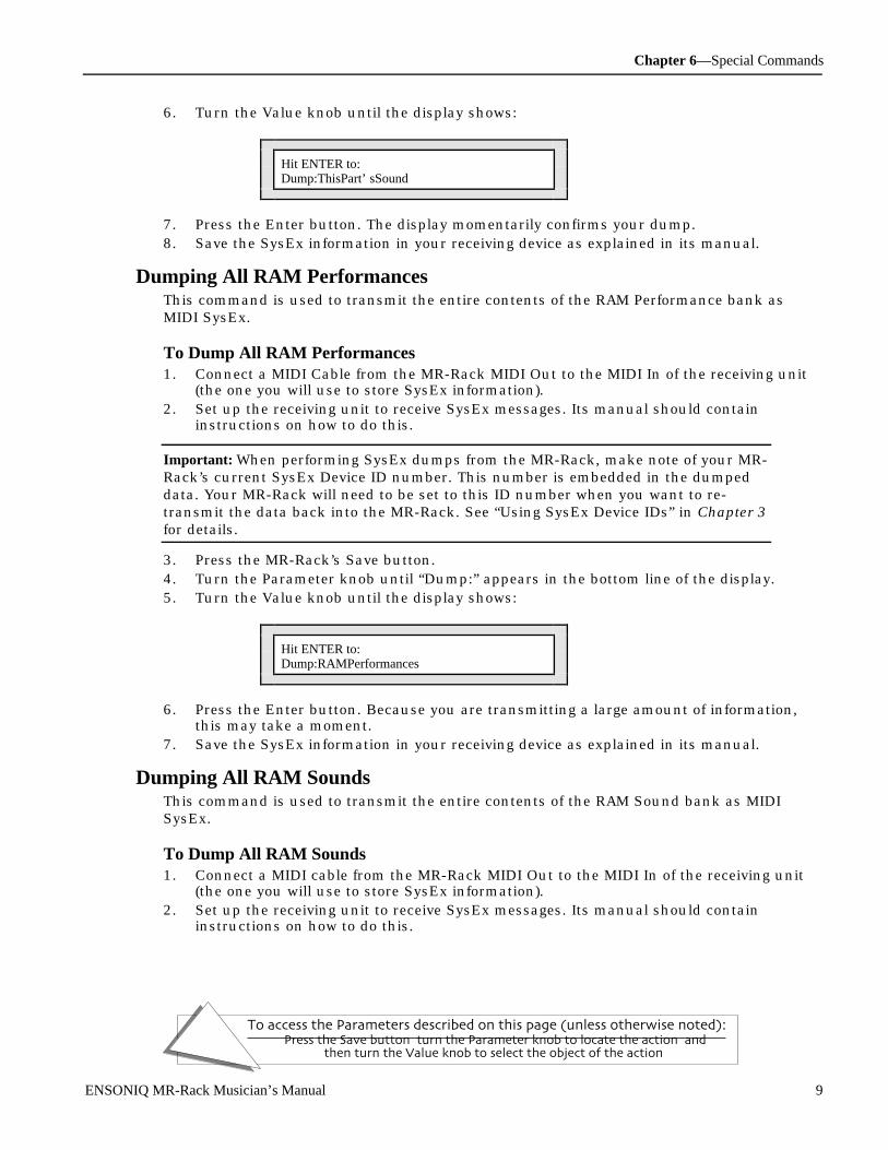
Chapter 6—Special Commands
To access the Parameters described on this page (unless otherwise noted):Press the Save button, turn the Parameter knob to locate the action, and
then turn the Value knob to select the object of the action.
ENSONIQ MR-Rack Musician’s Manual 9
6. Turn the Value knob until the display shows:
Hit ENTER to:Dump:ThisPart’ sSound
7. Press the Enter button. The display momentarily confirms your dump.8. Save the SysEx information in your receiving device as explained in its manual.
Dumping All RAM PerformancesThis command is used to transmit the entire contents of the RAM Performance bank asMIDI SysEx.
To Dump All RAM Performances1. Connect a MIDI Cable from the MR-Rack MIDI Out to the MIDI In of the receiving unit
(the one you will use to store SysEx information).2. Set up the receiving unit to receive SysEx messages. Its manual should contain
instructions on how to do this.
Important: When performing SysEx dumps from the MR-Rack, make note of your MR-Rack’s current SysEx Device ID number. This number is embedded in the dumpeddata. Your MR-Rack will need to be set to this ID number when you want to re-transmit the data back into the MR-Rack. See “Using SysEx Device IDs” in Chapter 3for details.
3. Press the MR-Rack’s Save button.4. Turn the Parameter knob until “Dump:” appears in the bottom line of the display.5. Turn the Value knob until the display shows:
Hit ENTER to:Dump:RAMPerformances
6. Press the Enter button. Because you are transmitting a large amount of information,this may take a moment.
7. Save the SysEx information in your receiving device as explained in its manual.
Dumping All RAM SoundsThis command is used to transmit the entire contents of the RAM Sound bank as MIDISysEx.
To Dump All RAM Sounds1. Connect a MIDI cable from the MR-Rack MIDI Out to the MIDI In of the receiving unit
(the one you will use to store SysEx information).2. Set up the receiving unit to receive SysEx messages. Its manual should contain
instructions on how to do this.
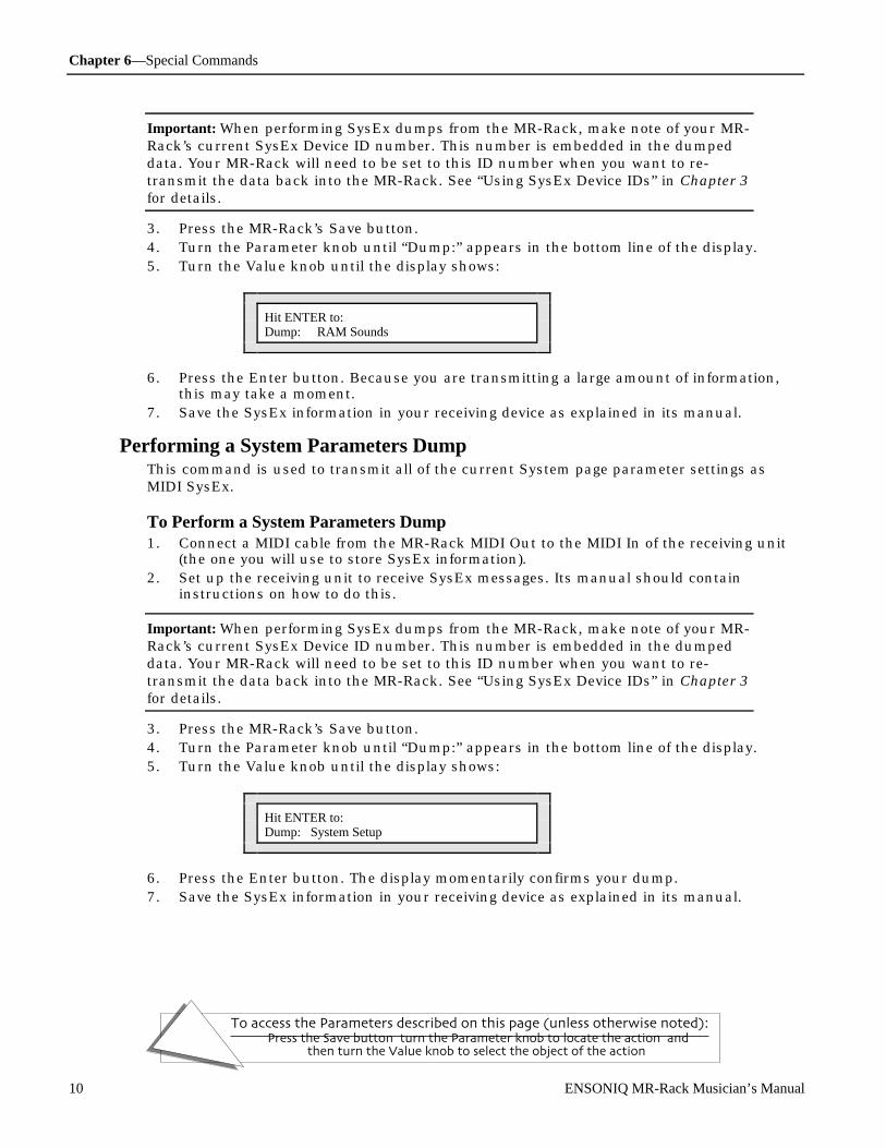
Chapter 6—Special Commands
To access the Parameters described on this page (unless otherwise noted):Press the Save button, turn the Parameter knob to locate the action, and
then turn the Value knob to select the object of the action.
10 ENSONIQ MR-Rack Musician’s Manual
Important: When performing SysEx dumps from the MR-Rack, make note of your MR-Rack’s current SysEx Device ID number. This number is embedded in the dumpeddata. Your MR-Rack will need to be set to this ID number when you want to re-transmit the data back into the MR-Rack. See “Using SysEx Device IDs” in Chapter 3for details.
3. Press the MR-Rack’s Save button.4. Turn the Parameter knob until “Dump:” appears in the bottom line of the display.5. Turn the Value knob until the display shows:
Hit ENTER to:Dump: RAM Sounds
6. Press the Enter button. Because you are transmitting a large amount of information,this may take a moment.
7. Save the SysEx information in your receiving device as explained in its manual.
Performing a System Parameters DumpThis command is used to transmit all of the current System page parameter settings asMIDI SysEx.
To Perform a System Parameters Dump1. Connect a MIDI cable from the MR-Rack MIDI Out to the MIDI In of the receiving unit
(the one you will use to store SysEx information).2. Set up the receiving unit to receive SysEx messages. Its manual should contain
instructions on how to do this.
Important: When performing SysEx dumps from the MR-Rack, make note of your MR-Rack’s current SysEx Device ID number. This number is embedded in the dumpeddata. Your MR-Rack will need to be set to this ID number when you want to re-transmit the data back into the MR-Rack. See “Using SysEx Device IDs” in Chapter 3for details.
3. Press the MR-Rack’s Save button.4. Turn the Parameter knob until “Dump:” appears in the bottom line of the display.5. Turn the Value knob until the display shows:
Hit ENTER to:Dump: System Setup
6. Press the Enter button. The display momentarily confirms your dump.7. Save the SysEx information in your receiving device as explained in its manual.
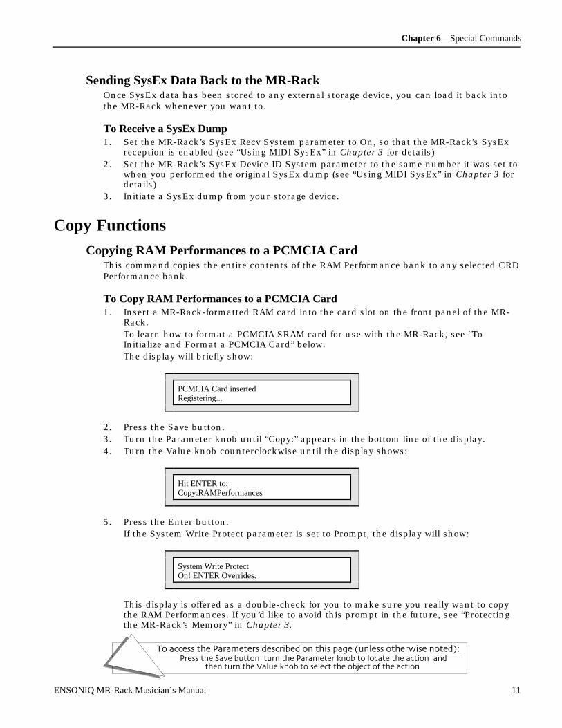
Chapter 6—Special Commands
To access the Parameters described on this page (unless otherwise noted):Press the Save button, turn the Parameter knob to locate the action, and
then turn the Value knob to select the object of the action.
ENSONIQ MR-Rack Musician’s Manual 11
Sending SysEx Data Back to the MR-RackOnce SysEx data has been stored to any external storage device, you can load it back intothe MR-Rack whenever you want to.
To Receive a SysEx Dump1. Set the MR-Rack’s SysEx Recv System parameter to On, so that the MR-Rack’s SysEx
reception is enabled (see “Using MIDI SysEx” in Chapter 3 for details)2. Set the MR-Rack’s SysEx Device ID System parameter to the same number it was set to
when you performed the original SysEx dump (see “Using MIDI SysEx” in Chapter 3 fordetails)
3. Initiate a SysEx dump from your storage device.
C opy Func t ions
Copying RAM Performances to a PCMCIA CardThis command copies the entire contents of the RAM Performance bank to any selected CRDPerformance bank.
To Copy RAM Performances to a PCMCIA Card1. Insert a MR-Rack-formatted RAM card into the card slot on the front panel of the MR-
Rack.To learn how to format a PCMCIA SRAM card for use with the MR-Rack, see “ToInitialize and Format a PCMCIA Card” below.The display will briefly show:
PCMCIA Card insertedRegistering...
2. Press the Save button.3. Turn the Parameter knob until “Copy:” appears in the bottom line of the display.4. Turn the Value knob counterclockwise until the display shows:
Hit ENTER to:Copy:RAMPerformances
5. Press the Enter button.If the System Write Protect parameter is set to Prompt, the display will show:
System Write ProtectOn! ENTER Overrides.
This display is offered as a double-check for you to make sure you really want to copythe RAM Performances. If you’d like to avoid this prompt in the future, see “Protectingthe MR-Rack’s Memory” in Chapter 3.
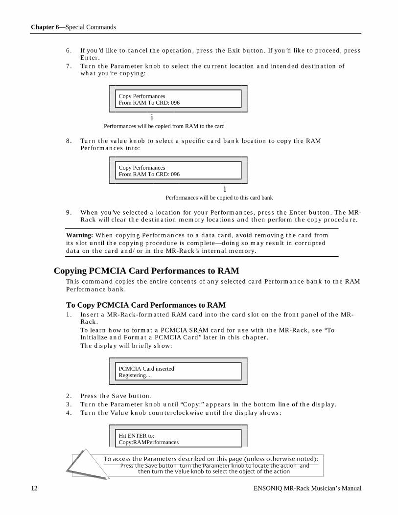
Chapter 6—Special Commands
To access the Parameters described on this page (unless otherwise noted):Press the Save button, turn the Parameter knob to locate the action, and
then turn the Value knob to select the object of the action.
12 ENSONIQ MR-Rack Musician’s Manual
6. If you’d like to cancel the operation, press the Exit button. If you’d like to proceed, pressEnter.
7. Turn the Parameter knob to select the current location and intended destination ofwhat you’re copying:
Copy PerformancesFrom RAM To CRD: 096
iPerformances will be copied from RAM to the card
8. Turn the value knob to select a specific card bank location to copy the RAMPerformances into:
Copy PerformancesFrom RAM To CRD: 096
iPerformances will be copied to this card bank
9. When you’ve selected a location for your Performances, press the Enter button. The MR-Rack will clear the destination memory locations and then perform the copy procedure.
Warning: When copying Performances to a data card, avoid removing the card fromits slot until the copying procedure is complete—doing so may result in corrupteddata on the card and/or in the MR-Rack’s internal memory.
Copying PCMCIA Card Performances to RAMThis command copies the entire contents of any selected card Performance bank to the RAMPerformance bank.
To Copy PCMCIA Card Performances to RAM1. Insert a MR-Rack-formatted RAM card into the card slot on the front panel of the MR-
Rack.To learn how to format a PCMCIA SRAM card for use with the MR-Rack, see “ToInitialize and Format a PCMCIA Card” later in this chapter.The display will briefly show:
PCMCIA Card insertedRegistering...
2. Press the Save button.3. Turn the Parameter knob until “Copy:” appears in the bottom line of the display.4. Turn the Value knob counterclockwise until the display shows:
Hit ENTER to:Copy:RAMPerformances

Chapter 6—Special Commands
To access the Parameters described on this page (unless otherwise noted):Press the Save button, turn the Parameter knob to locate the action, and
then turn the Value knob to select the object of the action.
ENSONIQ MR-Rack Musician’s Manual 13
5. Press the Enter button.If the System Write Protect parameter is set to Prompt, the display will show:
System Write ProtectOn! ENTER Overrides.
This display is offered as a double-check for you to make sure you really want to copythe RAM Performances. If you’d like to avoid this prompt in the future, see “Protectingthe MR-Rack’s Memory” in Chapter 3.
6. If you’d like to cancel the operation, press the Exit button. If you’d like to proceed, pressEnter.
7. Turn the Parameter knob to select the current location and intended destination ofwhat you’re copying:
Copy PerformancesTo RAM From CRD: 096
iPerformances will be copied to RAM from the card
8. Turn the value knob to select the specific card Performance bank location you want tocopy into RAM:
Copy PerformancesTo RAM From CRD: 096
i This Performance bank will be copied to RAM
9. Once you’ve selected the card Performance bank you want to copy into RAM, press theEnter button. The MR-Rack will clear the destination memory locations and thenperform the copy procedure.
Warning: When copying Performances from a data card, avoid removing the card fromits slot until the copy procedure is complete.
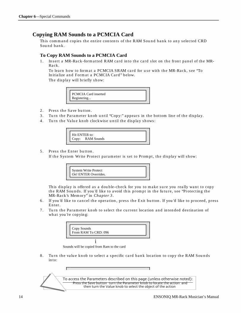
Chapter 6—Special Commands
To access the Parameters described on this page (unless otherwise noted):Press the Save button, turn the Parameter knob to locate the action, and
then turn the Value knob to select the object of the action.
14 ENSONIQ MR-Rack Musician’s Manual
Copying RAM Sounds to a PCMCIA CardThis command copies the entire contents of the RAM Sound bank to any selected CRDSound bank.
To Copy RAM Sounds to a PCMCIA Card1. Insert a MR-Rack-formatted RAM card into the card slot on the front panel of the MR-
Rack.To learn how to format a PCMCIA SRAM card for use with the MR-Rack, see “ToInitialize and Format a PCMCIA Card” below.The display will briefly show:
PCMCIA Card insertedRegistering...
2. Press the Save button.3. Turn the Parameter knob until “Copy:” appears in the bottom line of the display.4. Turn the Value knob clockwise until the display shows:
Hit ENTER to:Copy: RAM Sounds
5. Press the Enter button.If the System Write Protect parameter is set to Prompt, the display will show:
System Write ProtectOn! ENTER Overrides.
This display is offered as a double-check for you to make sure you really want to copythe RAM Sounds. If you’d like to avoid this prompt in the future, see “Protecting theMR-Rack’s Memory” in Chapter 3.
6. If you’d like to cancel the operation, press the Exit button. If you’d like to proceed, pressEnter.
7. Turn the Parameter knob to select the current location and intended destination ofwhat you’re copying:
Copy SoundsFrom RAM To CRD: 096
iSounds will be copied from Ram to the card
8. Turn the value knob to select a specific card bank location to copy the RAM Soundsinto:
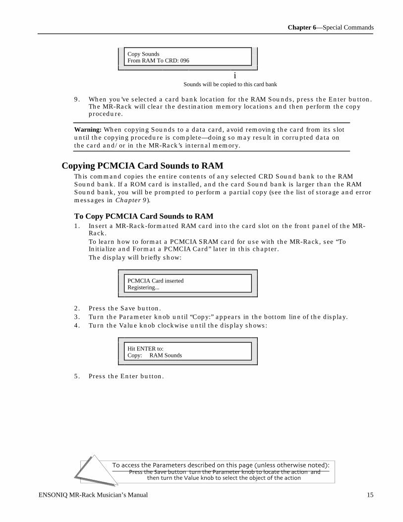
Chapter 6—Special Commands
To access the Parameters described on this page (unless otherwise noted):Press the Save button, turn the Parameter knob to locate the action, and
then turn the Value knob to select the object of the action.
ENSONIQ MR-Rack Musician’s Manual 15
Copy SoundsFrom RAM To CRD: 096
iSounds will be copied to this card bank
9. When you’ve selected a card bank location for the RAM Sounds, press the Enter button.The MR-Rack will clear the destination memory locations and then perform the copyprocedure.
Warning: When copying Sounds to a data card, avoid removing the card from its slotuntil the copying procedure is complete—doing so may result in corrupted data onthe card and/or in the MR-Rack’s internal memory.
Copying PCMCIA Card Sounds to RAMThis command copies the entire contents of any selected CRD Sound bank to the RAMSound bank. If a ROM card is installed, and the card Sound bank is larger than the RAMSound bank, you will be prompted to perform a partial copy (see the list of storage and errormessages in Chapter 9).
To Copy PCMCIA Card Sounds to RAM1. Insert a MR-Rack-formatted RAM card into the card slot on the front panel of the MR-
Rack.To learn how to format a PCMCIA SRAM card for use with the MR-Rack, see “ToInitialize and Format a PCMCIA Card” later in this chapter.The display will briefly show:
PCMCIA Card insertedRegistering...
2. Press the Save button.3. Turn the Parameter knob until “Copy:” appears in the bottom line of the display.4. Turn the Value knob clockwise until the display shows:
Hit ENTER to:Copy: RAM Sounds
5. Press the Enter button.
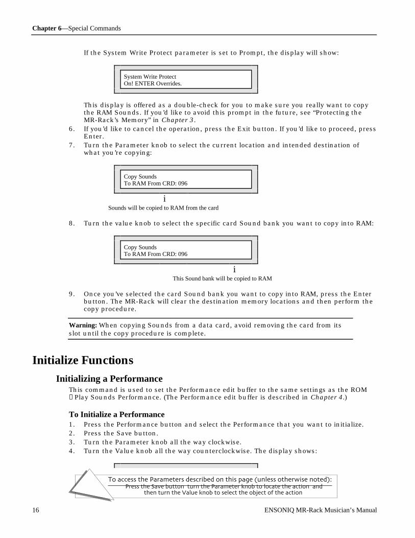
Chapter 6—Special Commands
To access the Parameters described on this page (unless otherwise noted):Press the Save button, turn the Parameter knob to locate the action, and
then turn the Value knob to select the object of the action.
16 ENSONIQ MR-Rack Musician’s Manual
If the System Write Protect parameter is set to Prompt, the display will show:
System Write ProtectOn! ENTER Overrides.
This display is offered as a double-check for you to make sure you really want to copythe RAM Sounds. If you’d like to avoid this prompt in the future, see “Protecting theMR-Rack’s Memory” in Chapter 3.
6. If you’d like to cancel the operation, press the Exit button. If you’d like to proceed, pressEnter.
7. Turn the Parameter knob to select the current location and intended destination ofwhat you’re copying:
Copy SoundsTo RAM From CRD: 096
iSounds will be copied to RAM from the card
8. Turn the value knob to select the specific card Sound bank you want to copy into RAM:
Copy SoundsTo RAM From CRD: 096
iThis Sound bank will be copied to RAM
9. Once you’ve selected the card Sound bank you want to copy into RAM, press the Enterbutton. The MR-Rack will clear the destination memory locations and then perform thecopy procedure.
Warning: When copying Sounds from a data card, avoid removing the card from itsslot until the copy procedure is complete.
Init ializ e F un ct ion s
Initializing a PerformanceThis command is used to set the Performance edit buffer to the same settings as the ROM→Play Sounds Performance. (The Performance edit buffer is described in Chapter 4.)
To Initialize a Performance1. Press the Performance button and select the Performance that you want to initialize.2. Press the Save button.3. Turn the Parameter knob all the way clockwise.4. Turn the Value knob all the way counterclockwise. The display shows:

Chapter 6—Special Commands
To access the Parameters described on this page (unless otherwise noted):Press the Save button, turn the Parameter knob to locate the action, and
then turn the Value knob to select the object of the action.
ENSONIQ MR-Rack Musician’s Manual 17
Hit ENTER to:Init:ThisPerformance
5. Press the Enter button.If the System Write Protect parameter is set to Prompt, the display will show:
System Write ProtectOn! ENTER Overrides.
This display is offered as a double-check for you to make sure you really want to erasethe current Performance. If you’d like to avoid this prompt in the future, see “Protectingthe MR-Rack’s Memory” in Chapter 3.
6. If you’d like to cancel the operation, press the Exit button. If you’d like to proceed, pressEnter. The display shows:
Sure? Hit ENTER to:Init:ThisPerformance
7. The MR-Rack is offering you a second chance to cancel the initialization. If you’d like tocancel the operation, press the Exit button. If you’re ready to initialize the currentPerformance, press the Enter button to execute the command.
Initializing an Effects SetupThis command is used to set the Effect setup in the currently selected Performance to thesettings in the ROM →PlaySounds Performance. For more information about the MR-RackEffects, see Chapter 5.
To Initialize an Effects Setup1. Press the Performance button and select the Performance that contains the Effects
setup that you want to initialize.2. Press the Save button.3. Turn the Parameter knob all the way clockwise.4. Turn the Value knob until the display shows:
Hit ENTER to:Init:ThisEffectSetup
5. Press the Enter button.

Chapter 6—Special Commands
To access the Parameters described on this page (unless otherwise noted):Press the Save button, turn the Parameter knob to locate the action, and
then turn the Value knob to select the object of the action.
18 ENSONIQ MR-Rack Musician’s Manual
If the System Write Protect parameter is set to Prompt, the display will show:
System Write ProtectOn! ENTER Overrides.
This display is offered as a double-check for you to make sure you really want to erasethe selected Effect setup. If you’d like to avoid this prompt in the future, see “Protectingthe MR-Rack’s Memory” in Chapter 3.
6. If you’d like to cancel the operation, press the Exit button. If you’d like to proceed, pressEnter. The display shows:
Sure? Hit ENTER to:Init:ThisEffectSetup
7. The MR-Rack is offering you a second chance to cancel the initialization. If you’d like tocancel the operation, press the Exit button. If you’re ready to initialize the selectedEffect setup, press the Enter button to execute the command.
Initializing a PerfEditKitThis command is used to set the PerfEditKit in the currently selected Performance to thePerfEditKit settings in the ROM →PlaySounds. For more information about using, creatingand editing Drum Kit Sounds, see Chapter 4.
To Initialize a PerfEditKit1. Press the Performance button and select the Performance that contains the PerfEditKit
that you want to initialize.2. Press the Save button.3. Turn the Parameter knob all the way clockwise.4. Turn the Value knob until the display shows:
Hit ENTER to:Init:ThisPerfEditKit
5. Press the Enter button.If the System Write Protect parameter is set to Prompt, the display will show:
System Write ProtectOn! ENTER Overrides.
This display is offered as a double-check for you to make sure you really want to erasethe selected PerfEditKit. If you’d like to avoid this prompt in the future, see “Protectingthe MR-Rack’s Memory” in Chapter 3.
6. If you’d like to cancel the operation, press the Exit button. If you’d like to proceed, pressEnter. The display shows:

Chapter 6—Special Commands
To access the Parameters described on this page (unless otherwise noted):Press the Save button, turn the Parameter knob to locate the action, and
then turn the Value knob to select the object of the action.
ENSONIQ MR-Rack Musician’s Manual 19
Sure? Hit ENTER to:Init:ThisPerfEditKit
7. The MR-Rack is offering you a second chance to cancel the initialization. If you’d like tocancel the operation, press the Exit button. If you’re ready to initialize the selectedPerfEditKit, press the Enter button to execute the command.
Initializing a Part’s SoundThis command is used to erase, or nullify, the Sound on the currently selected part. Anullified Sound takes up no memory, and is no longer visible when you’re selecting Sounds.
Note: This command is intended for Parts that are using Sounds other than thePerfEditKit. To initialize the PerfEditKit, see “Initializing a PerfEditKit” above.
To Initialize a Part’s Sound1. Press the Sound button, and use the Select Part buttons to find the Sound that you
want to initialize.2. Press the Save button.3. Turn the Parameter knob all the way clockwise.4. Turn the Value knob until the display shows:
Hit ENTER to:Init:ThisPart’sSound
5. Press the Enter button.If the System Write Protect parameter is set to Prompt, the display will show:
System Write ProtectOn! ENTER Overrides.
This display is offered as a double-check for you to make sure you really want to erasethe selected Sound. If you’d like to avoid this prompt in the future, see “Protecting theMR-Rack’s Memory” in Chapter 3.
6. If you’d like to cancel the operation, press the Exit button. If you’d like to proceed, pressEnter. The display shows:
Sure? Hit ENTER to:Init:ThisPart’sSound
7. The MR-Rack is offering you a second chance to cancel the initialization. If you’d like tocancel the operation, press the Exit button. If you’re ready to initialize the selectedSound, press the Enter button to execute the command.
Initializing RAM PerformancesThis command is used to set the entire contents of the RAM Performance bank to the
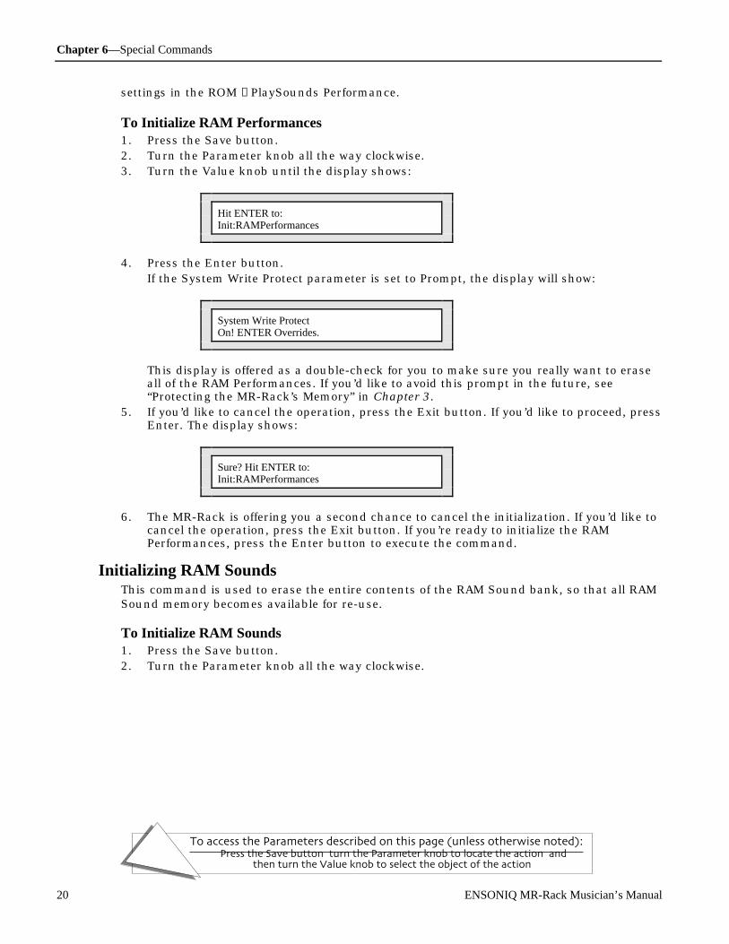
Chapter 6—Special Commands
To access the Parameters described on this page (unless otherwise noted):Press the Save button, turn the Parameter knob to locate the action, and
then turn the Value knob to select the object of the action.
20 ENSONIQ MR-Rack Musician’s Manual
settings in the ROM →PlaySounds Performance.
To Initialize RAM Performances1. Press the Save button.2. Turn the Parameter knob all the way clockwise.3. Turn the Value knob until the display shows:
Hit ENTER to:Init:RAMPerformances
4. Press the Enter button.If the System Write Protect parameter is set to Prompt, the display will show:
System Write ProtectOn! ENTER Overrides.
This display is offered as a double-check for you to make sure you really want to eraseall of the RAM Performances. If you’d like to avoid this prompt in the future, see“Protecting the MR-Rack’s Memory” in Chapter 3.
5. If you’d like to cancel the operation, press the Exit button. If you’d like to proceed, pressEnter. The display shows:
Sure? Hit ENTER to:Init:RAMPerformances
6. The MR-Rack is offering you a second chance to cancel the initialization. If you’d like tocancel the operation, press the Exit button. If you’re ready to initialize the RAMPerformances, press the Enter button to execute the command.
Initializing RAM SoundsThis command is used to erase the entire contents of the RAM Sound bank, so that all RAMSound memory becomes available for re-use.
To Initialize RAM Sounds1. Press the Save button.2. Turn the Parameter knob all the way clockwise.

Chapter 6—Special Commands
To access the Parameters described on this page (unless otherwise noted):Press the Save button, turn the Parameter knob to locate the action, and
then turn the Value knob to select the object of the action.
ENSONIQ MR-Rack Musician’s Manual 21
3. Turn the Value knob until the display shows:
Hit ENTER to:Init: RAM Sounds
4. Press the Enter button.If the System Write Protect parameter is set to Prompt, the display will show:
System Write ProtectOn! ENTER Overrides.
This display is offered as a double-check for you to make sure you really want to eraseall of the RAM Sounds. If you’d like to avoid this prompt in the future, see “Protectingthe MR-Rack’s Memory” in Chapter 3.
5. If you’d like to cancel the operation, press the Exit button. If you’d like to proceed, pressEnter. The display shows:
Sure? Hit ENTER to:Init: RAM Sounds
6. The MR-Rack is offering you a second chance to cancel the initialization. If you’d like tocancel the operation, press the Exit button. If you’re ready to initialize the RAM Sounds,press the Enter button to execute the command.
Initializing the System SetupThis command is used to reset all of the System page parameter settings to their originalvalues. For more information about the System parameters, see Chapter 3.
To Initialize the System Setup1. Press the Save button.2. Turn the Parameter knob all the way clockwise.3. Turn the Value knob until the display shows:
Hit ENTER to:Init: System Setup
4. Press the Enter button.

Chapter 6—Special Commands
To access the Parameters described on this page (unless otherwise noted):Press the Save button, turn the Parameter knob to locate the action, and
then turn the Value knob to select the object of the action.
22 ENSONIQ MR-Rack Musician’s Manual
If the System Write Protect parameter is set to Prompt, the display will show:
System Write ProtectOn! ENTER Overrides.
This display is offered as a double-check for you to make sure you really want to eraseyour System settings. If you’d like to avoid this prompt in the future, see “Protecting theMR-Rack’s Memory” in Chapter 3.
5. If you’d like to cancel the operation, press the Exit button. If you’d like to proceed, pressEnter. The display shows:
Sure? Hit ENTER to:Init: System Setup
6. The MR-Rack is offering you a second chance to cancel the initialization. If you’d like tocancel the operation, press the Exit button. If you’re ready to initialize the Systemparameters, press the Enter button to execute the command.
Formatting a PCMCIA CardIn order to save MR-Rack data on a PCMCIA SRAM data card, the card must be formattedfor use with the MR-Rack. This is achieved through the process of reinitialization. Initializinga card erases all data currently stored on the card and prepares it to receive new data fromthe MR-Rack.
Only PCMCIA SRAM cards—such as ENSONIQ’s MC-512—should be used for MR-Rackmemory storage.
To Initialize and Format a PCMCIA Card1. Insert a PCMCIA RAM card into the Data Card slot on the front panel of the MR-Rack.2. Press the Save button.3. Turn the Parameter knob all the way clockwise.4. Turn the Value knob until the display shows:
Hit ENTER to:Init: PCMCIA Card
5. Press the Enter button.If the System Write Protect parameter is set to Prompt, the display will show:
System Write ProtectOn! ENTER Overrides.
This display is offered as a double-check for you to make sure you really want to erasePCMCIA card. If you’d like to avoid this prompt in the future, see “Protecting the MR-Rack’s Memory” in Chapter 3.
6. If you’d like to cancel the operation, press the Exit button. If you’d like to proceed, press

Chapter 6—Special Commands
To access the Parameters described on this page (unless otherwise noted):Press the Save button, turn the Parameter knob to locate the action, and
then turn the Value knob to select the object of the action.
ENSONIQ MR-Rack Musician’s Manual 23
Enter. The display shows:
Sure? Hit ENTER to:Init: PCMCIA Card
7. The MR-Rack is offering you a second chance to cancel the initialization. If you’d like tocancel the operation, press the Exit button. If you’re ready to initialize your PCMCIAcard, press the Enter button to execute the command.
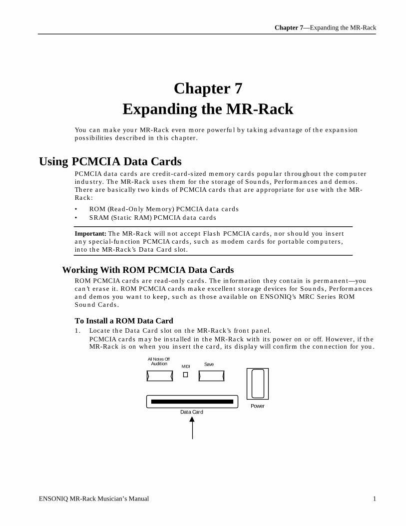
Chapter 7—Expanding the MR-Rack
ENSONIQ MR-Rack Musician’s Manual 1
Ch apt e r 7Expan di ng t he M R- Rac k
You can make your MR-Rack even more powerful by taking advantage of the expansionpossibilities described in this chapter.
U sing PC MC I A D at a C ar dsPCMCIA data cards are credit-card-sized memory cards popular throughout the computerindustry. The MR-Rack uses them for the storage of Sounds, Performances and demos.There are basically two kinds of PCMCIA cards that are appropriate for use with the MR-Rack:
• ROM (Read-Only Memory) PCMCIA data cards• SRAM (Static RAM) PCMCIA data cards
Important: The MR-Rack will not accept Flash PCMCIA cards, nor should you insertany special-function PCMCIA cards, such as modem cards for portable computers,into the MR-Rack’s Data Card slot.
Working With ROM PCMCIA Data CardsROM PCMCIA cards are read-only cards. The information they contain is permanent—youcan’t erase it. ROM PCMCIA cards make excellent storage devices for Sounds, Performancesand demos you want to keep, such as those available on ENSONIQ’s MRC Series ROMSound Cards.
To Install a ROM Data Card1. Locate the Data Card slot on the MR-Rack’s front panel.
PCMCIA cards may be installed in the MR-Rack with its power on or off. However, if theMR-Rack is on when you insert the card, its display will confirm the connection for you.
All Notes OffAudition
MIDI Save
Data CardPower

Chapter 7—Expanding the MR-Rack
2 ENSONIQ MR-Rack Musician’s Manual
2. Turn your data card label-side-up, with its connector edge facing away from you.
Label
connector edge
3. Slide the card firmly into the MR-Rack’s Data Card slot until you hear it click as itmakes contact with the MR-Rack’s internal card socket.
If the MR-Rack is powered up, SoundFinder will begin quickly cataloging the Soundsand Performances on the card. The display will reflect its progress:
Registering Card...096:027 Speed Demon
i i iBank and Sound numbers Sound Names
When SoundFinder has finished cataloging the card’s Sounds and Performances, it willrefind the last Sound selected for each Sound Type, and designate it as the category’sfavorite, for your convenience.If you insert a data card when the MR-Rack’s power is off, this process will occur duringthe power-up sequence.Updating the SoundFinder database and re-establishing favorites takes a few moments.The length of this process is determined by the size of the card and the number ofbanks it contains.

Chapter 7—Expanding the MR-Rack
ENSONIQ MR-Rack Musician’s Manual 3
Warning: Avoid removing the card from its slot while it’s being registered—doing somay result in corrupted data on the card and/or in the MR-Rack’s internal memory.
Tip: If the MR-Rack refuses to register the card, try inserting it again. If any othermessage is displayed, consult Chapter 9 for an explanation of the error messageyou’ve encountered.
To Remove a ROM Data CardYou can remove a data card from the MR-Rack with its power on or off.
1. Remove the data card from its slot by pulling it toward you.If the MR-Rack’s power is on, its display will show:
PCMCIA Card RemovedUnregistering...
Note: Performances or Drum Kit Sounds that used Sounds from the data card you’vejust removed will display **EMPTY** in place of any no-longer available card Sounds.
Accessing a ROM Card’s Sounds, Performances and DemosAll of the Sounds, Performances and demos on your ROM card can be selected in exactly thesame manner as your onboard Sounds, Performances and demos. You’ll find a newSoundFinder category has appeared—CRD—containing your new materials.
Working With SRAM PCMCIA Data CardsSRAM PCMCIA data cards are intended as additional storage space for your MR-RackSounds and Performances. The MR-Rack can use SRAM cards of three different memorycapacities:
• 512k cards—provide 4 additional Sound/Performance banks• 1 megabyte cards—provide 9 additional Sound/Performance banks• 2 megabyte cards—provide 18 additional Sound/Performance banks
PCMCIA cards can be purchased inexpensively from vendors of computer equipment andfrom ENSONIQ, which offers the MC-512 PCMCIA SRAM card.
SRAM PCMCIA Cards and BatteriesTo maximize battery life, many SRAM PCMCIA cards are shipped without a battery. Beforeusing these cards, you must first install the correct-size battery.
To Install the Battery in an SRAM PCMCIA Card1. Slide the switch away from the battery drawer to release the drawer.

Chapter 7—Expanding the MR-Rack
4 ENSONIQ MR-Rack Musician’s Manual
+
the battery drawer switchshould be pushed to theright
the battery drawer
Note that the second switch to the right in the illustration above is the write-protectswitch, which is used to prevent accidental erasure of card files.
2. Pull gently on the plastic tab at the top of the battery drawer to open it.3. Insert the battery in the battery drawer with the flat (+) side of the battery facing up.4. Slide the battery drawer closed.5. Slide the switch toward the battery drawer to lock the battery drawer closed.
Tip: If you need to change your card’s battery—but don’t want to lose what you’ve gotsaved on the card—you can change the battery while the card is installed in the MR-Rack and the MR-Rack’s power is on. Be careful not to turn the MR-Rack’s power offor remove the card until its new battery has been installed.
To Install a New SRAM Data CardIt’s best to install an SRAM PCMCIA data card with the MR-Rack’s power on and with thecard’s write-protect switch set to the “off” position.
battery-drawer switchwrite-protect switchshould be pushed tothe right
Label
1. Locate the Data Card slot on the MR-Rack’s front panel.

Chapter 7—Expanding the MR-Rack
ENSONIQ MR-Rack Musician’s Manual 5
All Notes OffAudition
MIDI Save
Data CardPower
2. Turn your data card label-side-up, with its connector edge facing away from you.
Label
connector edge
3. Slide the card into the MR-Rack’s Data Card slot until you feel it making contact withthe MR-Rack’s internal card socket.
4. The MR-Rack display will show:
PCMCIA Card Inserted* Unformatted Card *
Before using an SRAM data card to store Sounds and Performances, the card must be

Chapter 7—Expanding the MR-Rack
6 ENSONIQ MR-Rack Musician’s Manual
formatted for the MR-Rack through the process of initialization. This takes only a fewmoments.
To Initialize and Format a PCMCIA Card1. Press the Save button.2. Turn the Parameter knob all the way clockwise.3. Turn the Value knob until the display shows:
Hit ENTER to:Init: PCMCIA Card
4. Press the Enter button.If the System Write Protect parameter is set to Prompt, the display will show:
System Write ProtectOn! ENTER overrides.
This display is offered as a double-check for you, to make sure you really want to erasePCMCIA card. If you’d like to avoid this prompt in the future, see “Protecting the MR-Rack’s Memory” in Chapter 3.
5. If you’d like to cancel the operation, press the Exit button. If you’d like to proceed, pressEnter. The display shows:
Sure? Hit ENTER to:Init: PCMCIA Card
6. The MR-Rack is offering you a second chance to cancel the initialization. If you’d like tocancel the operation, press the Exit button. If you’re ready to initialize your PCMCIAcard, press the Enter button to execute the command.The display will confirm the initialization and registration of the card.
To Install an Already-Formatted SRAM Data Card1. Follow steps 1-3 of “To Install a New SRAM Data Card.”
If the MR-Rack is powered up, SoundFinder will begin quickly cataloging the Soundsand Performances on the card. The display will reflect its progress:
Registering Card...096:027 Speed Demon
i i iBank and Sound numbers Sound names
When SoundFinder has finished cataloging the card’s Sounds and Performances, it willrefind the last Sound selected for each Sound Type, and designate it as the category’sfavorite, for your convenience.If you insert a data card when the MR-Rack’s power is off, this process will occur during

Chapter 7—Expanding the MR-Rack
ENSONIQ MR-Rack Musician’s Manual 7
the power-up sequence.Updating the SoundFinder database and re-establishing favorites takes a few moments.The length of this process is determined by the size of the card and the number ofbanks it contains.
Warning: Avoid removing the card from its slot while it’s being registered—doing somay result in corrupted data on the card and/or in the MR-Rack’s internal memory.
Tip: If the MR-Rack refuses to register the card, try inserting it again. If any othermessage is displayed, consult Chapter 9 for an explanation of the error messageyou’ve encountered.
To Remove an SRAM Data CardYou can remove a data card from the MR-Rack with its power on or off.
1. Remove the data card from its slot by pulling it toward you.If the MR-Rack’s power is on, its display will show:
PCMCIA Card RemovedUnregistering...
Accessing an SRAM Card’s Sounds, Performances and DemosAll of the Sounds, Performances and demos on your SRAM card can be selected in exactlythe same manner as your onboard Sounds, Performances and demos. You’ll find a newSoundFinder category has appeared—CRD—containing your new materials.
Note: Saving and copying Performances, Sounds, Effect Set-Ups and PerfEditKits toand from data cards is discussed in Chapter 6.
U sing EN SON IQ EX P Se r ie s Wave Expansion Boar dsThe MR-Rack is shipped from ENSONIQ’s factory with a powerful 12 megabytes of 16-bitwave data, at a CD-quality sample playback rate of 44.1kHz. By installing ENSONIQ’s EXPSeries Wave Expansion Boards, you can bring the MR-Rack’s wave data memory up to agigantic 84 megabytes. The MR-Rack can accommodate three EXP Series Wave Expansionboards, which supply new Sounds, Performances and demos as well as up to 24 megabytesof new wave data on each board. You can easily install EXP Series Wave Expansion Boardsyourself—this chapter describes how.
An Important Note About Electro Static DischargeMany of the internal components in the MR-Rack, as well as expansion boards, aresusceptible to Electro Static Discharge (ESD), commonly known as “static.” Electro staticdischarge can destroy or damage electronic devices. Here are some procedures you canfollow when handling electronic devices in order to minimize the possibility of causing ESDdamage:
1. Before opening your MR-Rack or handling the expansion boards, you should be

Chapter 7—Expanding the MR-Rack
8 ENSONIQ MR-Rack Musician’s Manual
grounded—use a ground strap to discharge any static electric charge built up on yourbody. The ground strap attaches to your wrist and a ground source allowing your handsthe freedom to work.
2. Avoid any unnecessary movement, such as scuffing your feet when handling electronicdevices, since most movement can generate additional charges of static electricity.
3. Minimize the handling of the expansion boards. Keep them in their static-free packagesuntil needed. Transport or store the expansion boards only in their protective packages.
4. When handling the expansion boards, avoid touching the connector pins. Try to handlethe expansion boards by the edges only.
If you have any questions concerning the use of the MR-Rack or expansion boards, or foradditional technical support, please contact ENSONIQ Customer Service at (610) 647-3930Monday through Friday 9:30 a.m. to 12:15 p.m. and 1:15 p.m. to 6:30 p.m. Eastern Time.
Inst alling and R e m oving Expansion Boar dsThe MR-Rack can use up to three discrete expansion boards at any one time. Expansionboards are easily installed. Here’s how:
How To Install an Expansion Board1. Turn the MR-Rack off, and unplug it from its AC outlet.2. Remove the six Phillips-head screws from the MR-Rack lid. The screws are located at
the arrows shown below:
3. Remove the lid from the MR-Rack by lifting the back of the lid slightly, and sliding itaway from the unit.
4. Examine the inside of the MR-Rack, and locate the three expansion board slots. Noticethat each slot has a 50-pin connector (toward the back of the unit) and a 40-pinconnector (toward the front).

Chapter 7—Expanding the MR-Rack
ENSONIQ MR-Rack Musician’s Manual 9
1
2
3
5. Examine your expansion board. Notice that it, too, has both a 50-pin and 40-pinconnector.
6. Position your expansion board above the lowest numbered empty slot and align theconnectors.
Important: Expansion boards must be installed in the lowest numbered availablelocations, or the MR-Rack may not recognize them.
7. Press the expansion board down firmly into its location so that it makes a physical (andelectrical) connection with your MR-Rack. The expansion board’s connectors must beinserted into both of the chassis’ connectors in order to work properly.
8. Slide the lid into the front panel extrusion, and lower it into place.9. Reinstall the six screws that hold the lid down.10. Plug the MR-Rack into an outlet, power it up, and follow the instructions in “To Identify
an Installed Expansion Board,” below to verify that the MR-Rack is properly recognizingthe expansion board.
How To Remove an Expansion Board1. Turn the MR-Rack off, and unplug it from its AC outlet.2. Remove the six Phillips-head screws from the MR-Rack lid. The screws are located at
the arrows shown below:

Chapter 7—Expanding the MR-Rack
10 ENSONIQ MR-Rack Musician’s Manual
3. Remove the lid from the MR-Rack by lifting the back of the lid slightly, and sliding itaway from the unit.
4. Examine the inside of the MR-Rack, and locate the expansion board you’d like toremove, as shown in the following illustration.
3
2
1
5. Grab the expansion board you want to remove by its edges and gently lift it straightupwards out of its socket to remove it.
Important: Expansion boards must be installed in the lowest numbered availablelocation. If you’ve removed the Number 1 or 2 expansion board, re-install theremaining boards in the lowest available slots.
7. Slide the lid into the front panel extrusion, and lower it into place.8. Reinstall the six screws that hold the lid down.9. Plug the MR-Rack into an outlet, power it up, and follow the instructions in “To Identify
an Installed Expansion Board,” below to verify that the MR-Rack is properly recognizingany remaining expansion boards.
Note: Performances or Drum Kits that used Sounds from the expansion board you’vejust removed will display **EMPTY** in place of any no-longer available expansionboard Sounds.
To Identify an Installed Expansion Board1. Press the System button.2. Turn the Parameter knob until the display shows:
System parameters:WaveEXP1:xxxxxxxxxxx
iExpansion board name
When an expansion board is installed, this read-only display will show the name of theexpansion board located in the first slot.
3. Turning the Parameter knob two more times will show the names of the expansionboards in Wave EXP Slots 2 and 3 (if they’re installed).
If there are no expansion boards installed, the display will show “WaveEXP1= **EMPTY**.”

Chapter 7—Expanding the MR-Rack
ENSONIQ MR-Rack Musician’s Manual 11
Note: If you’ve installed expansion boards and the MR-Rack appears not to berecognizing them, carefully repeat the instructions in “How To Install an ExpansionBoard.” If the MR-Rack still doesn’t recognize the expansion board, call ENSONIQCustomer Service at 610-647-3930.
U pdat ing the M R - R ac k Ope rat ing Syst e m With most electronic devices, operating system upgrades have become common. ForENSONIQ products, an operating system upgrade provides system enhancements, and attimes offers additional features.
You can find out what the current operating system is by calling ENSONIQ CustomerService at (610) 647-3930, or the the ENSONIQ Fax Retrieval System at (800) 257-1439. Wesuggest requesting the complete catalog of available documents. The Fax Retrieval Systemoffers over 200 documents covering all of the ENSONIQ products, and a variety of relatedissues. Document 0010 is the current O.S. list. If you’re online, you can visit the ENSONIQlocations on CompuServe (at “GO ENSONIQ”) or on the World Wide Web at“www.ensoniq.com.” An up-to-date O.S. list for all ENSONIQ products can also be found inthe Transoniq Hacker, a third-party monthly publication (for more information on theHacker, call 1-503-227-6848).
Learning the Version Number of Your MR-Rack Operating SystemYou can easily find out what operating system (or “O.S.”) your MR-Rack is currently using.
To Find the Operating System1. Press the Save button and hold it down.2. While still holding the Save button, press the System button.
The display briefly shows your current Operating System:
ENSONIQ MR-RACKO.S. Version: #.##

Chapter 8—Insert Effect Parameters
ENSONIQ MR-Rack Musician’s Manual 1
Ch apt e r 8In se rt Ef f e c t Par am e t er s
This chapter offers detailed descriptions of the Insert Effects and their related parameters.For a basic overview of how the effects work in the MR-Rack, see Chapter 5 — Effects.
To access the functions you’ll find in this chapter, follow these steps:
1. Press the Effects button.When you first press the Effects button, its yellow LED will light.
Performance System Effects
Sound Params Mute
Part
Bypass
2. Turn the Parameter knob all the way counterclockwise. The display shows:
Hit ENTER to edit:Insert Effect
3. Press the Enter button.
The MR-Rack provides many options for routing, assigning, and editing effects. Each ofthese options is called a parameter. When you change the setting of a parameter, you areediting the parameter’s value.
To select Effect parameters, turn the Parameters knob. To edit an Effect parameter’s value,turn the Value knob.
Parameter Value

Chapter 8—Insert Effect Parameters
To access the Parameters described on this page (unless otherwise noted):Press Effects, turn the Parameter knob to select Insert Effect, and press Enter. Turn the Parameter
knob to select the parameter, and use the Value knob to change the parameter's Setting.
2 ENSONIQ MR-Rack Musician’s Manual
List of M R - R ac k Ins er t Ef f e c t sThe following is a list of the Insert Effects in the order that they appear in the MR-Rack:
01 Parametric EQ 15 Chorus→Rev 29 ResVCF→DDL02 Hall Reverb 16 Flanger→Rev 30 Dist→VCF→DDL03 Large Room 17 Phaser→Rev 31 Pitch Detuner04 Small Room 18 EQ→Reverb 32 Chatter Box05 Large Plate 19 Spinner→Rev 33 Formant Morph06 Small Plate 20 DDL→Chorus 34 RotarySpeaker07 NonLinReverb1 21 DDL→Flanger 35 Tunable Spkr08 NonLinReverb2 22 DDL→Phaser 36 Guitar Amp09 Gated Reverb 23 DDL→EQ 37 Dist→DDL→Trem10 Stereo Chorus 24 Multi-Tap DDL 38 Comp→Dist→DDL11 8-VoiceChorus 25 Dist→Chorus 39 EQ→Comp→Gate12 Rev→Chorus 26 Dist→Flanger 40 EQ→Chorus→DDL13 Rev→Flanger 27 Dist→Phaser14 Rev→Phaser 28 Dist→AutoWah
List of Ef f e c t M odulat or sHere is a list of the effect modulators available within the MR-Rack:
Off No effect modulation.FullModAmt Full on, all the time; destination always modulated to Mod Amt Max.Velocity Last velocity received; filtered by VelocityRange and VelocityMode.Vel+Pressure Addition of last velocity received & highest poly/channel pressure value; both filtered.+PosMIDIkey# Last MIDI key number received (0-127); filtered by Key Range. Centered on MIDI note 64.-NegMIDIkey# Inverted response of the absolute MIDI key number. Centered on MIDI note 64.Pressure Highest poly or channel value; filtered by Key Range & PressureMode; 0 when Off.PitchWheel Last pitch wheel value; filtered by Pitch Bend Recv.ModWheel Last mod wheel value; filtered by Mod Wheel(1)Recv.Wheel+Press Addition of last mod wheel value & highest poly or channel value; both filtered.FootPedal Last foot pedal value; filtered by FootPedal(4) Recv.Sustain Last sustain value; filtered by Sustain/SostRecv.Sostenuto Last sostenuto value; filtered by Sustain/SostRecv.SysCTRL1 Last assignable controller 1 value; filtered by CTRL1 Recv.SysCTRL2 Last assignable controller 2 value; filtered by CTRL2 Recv.SysCTRL3 Last assignable controller 3 value; filtered by CTRL3 Recv.SysCTRL4 Last assignable controller 4 value; filtered by CTRL4 Recv.
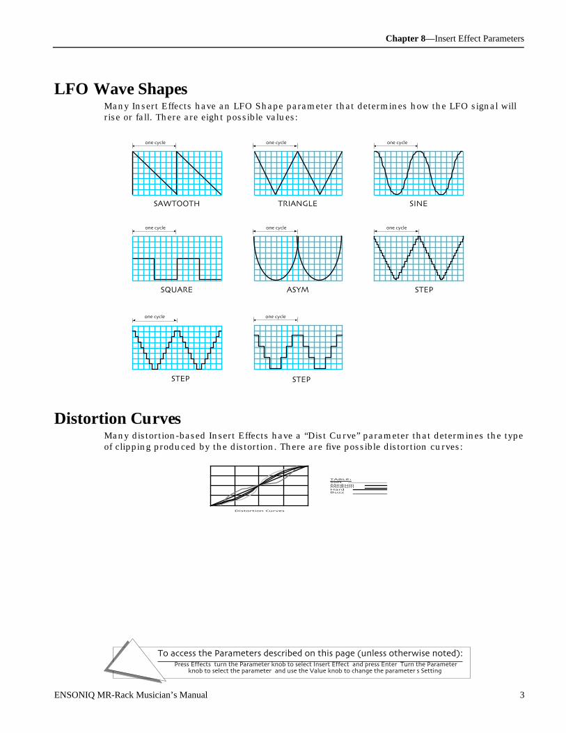
Chapter 8—Insert Effect Parameters
To access the Parameters described on this page (unless otherwise noted):Press Effects, turn the Parameter knob to select Insert Effect, and press Enter. Turn the Parameter
knob to select the parameter, and use the Value knob to change the parameter's Setting.
ENSONIQ MR-Rack Musician’s Manual 3
LF O Wave Shape sMany Insert Effects have an LFO Shape parameter that determines how the LFO signal willrise or fall. There are eight possible values:
TRIANGLE
0
+100
-100
one cycle
SAWTOOTH
0
+100
-100
one cycle
SINE
0
+100
-100
one cycle
SQUARE
0
+100
-100
one cycle
ASYM
0
+100
-100
one cycle
4-STEP
0
+100
-100
one cycle
8-STEP
0
+100
-100
one cycle
16-STEP
0
+100
-100
one cycle
D ist or t ion C u rve sMany distortion-based Insert Effects have a “Dist Curve” parameter that determines the typeof clipping produced by the distortion. There are five possible distortion curves:
Distortion Curves
0.5
0
1
-0.5
-1
TABLE:Soft=Medium 1=Medium 2=Hard=Buzz=
0.50 1-0.5-1

Chapter 8—Insert Effect Parameters
To access the Parameters described on this page (unless otherwise noted):Press Effects, turn the Parameter knob to select Insert Effect, and press Enter. Turn the Parameter
knob to select the parameter, and use the Value knob to change the parameter's Setting.
4 ENSONIQ MR-Rack Musician’s Manual
Inse r t Ef f e c t Par am e t e r sThe following is a description of the Insert Effects and their related parameters. Parametersthat are common to all Insert Effects, and the modulation parameters are defined in Chapter5 — Effects.
Common Insert Effect ParametersPreset GlobalReverb AmtInput Mix Insert FX to Global Chorus Mix
Common Modulation ParametersMod Src Mod Src Max Dest MinMod Src Min Dest Dest Max
Inse r t Ef f e c t De sc r ipt ions
01 Parametric EQ
OutputLo Shelf
Right
Left
Mid 1L
REQ Input
Mid 2EQ Output
Hi Shelf
This Insert Effect offers a minimum phase, four-band parametric EQ.
Parameter Range DescriptionEQ Input Off, -49.5dB to +24dB Adjusts the input level trim to the EQs to eliminate the possibility of
clipping boosted signals.LoShelf Fc 10Hz to 20.0kHz Sets the center of the low frequency EQ.LoShelf Gain Off, -49.5dB to +24dB Sets the amount of boost or cut applied to this low frequency shelf.Mid 1 Fc 10Hz to 20.0kHz Sets the center of the mid frequency parametric.Mid 1 Q 1.0 to 40.0 Bandwidth control that determines the width of the resonant peak at the
center frequency band. This parameter is equal to the cutoff frequencydivided by the bandwidth. By raising the value, you can produce anarrower bandwidth.
Mid 1 Gain Off, -49.5dB to +24dB Sets the amount of boost or cut applied to this mid frequency parametric.Mid 2 Fc 10Hz to 20.0kHz Identical to the Mid 1 Fc parameter, and is used to control different
bandwidths within the mid range.Mid 2 Q 1.0 to 40.0 Identical to the Mid 1 Q parameter, and is used to control different
bandwidths within the mid range.Mid 2 Gain Off, -49.5dB to +24dB Identical to the Mid 1 Gain parameter, used to control different
bandwidths within the mid range.HiShelf Fc 10Hz to 20.0kHz Sets the center frequency of the high frequency shelf.HiShelf Gain Off, -49.5dB to +24dB Sets the amount of boost or cut applied to this high frequency shelf.EQ Output Off, -49.5dB to +24dB Controls the gain coming out of the parametric EQ.
02 Hall Reverb

Chapter 8—Insert Effect Parameters
To access the Parameters described on this page (unless otherwise noted):Press Effects, turn the Parameter knob to select Insert Effect, and press Enter. Turn the Parameter
knob to select the parameter, and use the Value knob to change the parameter's Setting.
ENSONIQ MR-Rack Musician’s Manual 5
03 Large Room
04 Small RoomHall Reverb is a large acoustic space, and provides a high density reverb. Large Room reverbprovides ambience, and Small Room reverb simulates the ambience of a small room.
Parameter Range DescriptionDecay 0sec to 12.7sec
(Hall setting)0sec to 10.0sec(Room settings)
Controls the amount of time it takes for the reverberation to decay to avery low level after the input signal stops. Higher values arerecommended for the hall reverb.
LF Decay -99% to +99% Functions as a tone control and boosts (when set to a positive value) orcuts (when set to a negative value) the rate at which low frequencies willdecay.
HF Damping 100Hz to 21.2kHz Controls the rate of attenuation of high frequencies in the decay of thereverberation. As natural reverb decays, some high frequencies tend toget absorbed by the environment. Increasing the value of this parameterwill gradually filter out (dampen) more and more high frequency energy.
HF Bandwidth 100Hz to 21.2kHz The high frequency bandwidth acts as a low pass filter on the signalgoing into the reverb, controlling the amount of high frequencies that willpass into the effect. The higher the setting, the more high frequencies areallowed to pass.
Primary Send -99% to +99% Controls the level of the diffused input signal into the reverb definition.Diffusion 1 0 to 100 Smears the input signal transients, to diffuse and smooth the sound.
Lower values will cause impulse sounds to appear as a series of discreteechoes, while higher values tend to increase the smear (smoothersounding with fewer discrete echoes). We recommend settings of 50 forstarters.
Diffusion 2 0 to 100 This parameter, similar to and in series with Diffusion1, performs thesame way but controls lower frequency ranges. Experiment with differentlevels between the diffusion parameters to find the settings that are rightfor your source.
Definition 0 to 100 Controls the rate at which echo density is increased with time. Settingthis parameter too high can cause the echo density to build at a rate whichexceeds the decay rate. A general rule of thumb is this: Definition shouldnot exceed the LF Decay time added to the Decay time.
Detune Rate 0.00Hz to 1.54Hz Controls the LFO rate of detuning introduced into the reverberationdecay. Detuning creates a slight oscillating pitch shift into the decay,giving it a more natural sound by breaking up resonant modes.
Detune Depth 0% to 100% Controls the depth of the detuning, that is, how much the pitch willchange. Low values yield a metallic sound. Some sounds may requirevery low values, while others sound more natural with higher values.
PreDelay 0 to 36ms Controls the amount of time it takes for the original signal to bepresented to the reverb. Higher values denote a longer delay.
ER 1 Time 0 to 112ms Controls the delay time for the first pre-echo. Pre-echoes are the firstsounds reflected back from the walls or reflective “live” surfaces. Highervalues delay the diffused signal more.
ER 1 Send -99% to +99% Controls the level of the first pre-echo, with the echo routed directly tothe output.
ER 1 Level -99% to +99% Controls the level of the first pre-echo. This pre-level controls the echosend to the Definition.
ER 2 Time 0 to 112ms Controls the delay time for the second pre-echo.ER 2 Send -99% to +99% Controls the level of the second pre-echo, with the echo routed directly to
the output.ER 2 Level -99% to +99% Controls the level of the second pre-echo. As a signal continues to
bounce off the different reflective surfaces (walls), it decreases involume. Set this parameter to a lower value than Ref 1 Level, in order tocreate a natural sounding echo.

Chapter 8—Insert Effect Parameters
To access the Parameters described on this page (unless otherwise noted):Press Effects, turn the Parameter knob to select Insert Effect, and press Enter. Turn the Parameter
knob to select the parameter, and use the Value knob to change the parameter's Setting.
6 ENSONIQ MR-Rack Musician’s Manual
Position 1Position 2Position 3
-99% to +99%-99% to +99%-99% to +99%
These parameters simulate the depth of the hall. Think of them as threedifferent microphones placing at various distances within the hall(Position 1 is closest to the front, and Position 3 is farthest from thefront). When the range (volume) is higher for Position 1, the soundappears closer to the front, whereas a higher setting for Position 3appears farther from the front, suggesting a deeper (wetter) hall.
Output Bal Full <L to Full >R Controls the output of the hall reverb in the stereo field.
05 Large Plate
06 Small PlateA plate reverb takes the vibrations from a metal plate and uses them to create a metallicsounding reverb. Large plate reverbs are often used to enhance a vocalist’s performance,and small plate reverbs are often used in the studio for drums and percussion.
Parameter Range DescriptionDecay 0sec to 10.0sec Controls the amount of time it takes for the reverberation to decay away
to a very low level after the input signal stops. High values of decaysound good on plate reverbs.
HF Damping 100Hz to 21.2kHz Increasing the value of this parameter will gradually filter out increasingamounts of high frequency energy. Higher values yield an abrupt decay.This parameter controls the cut off of a low pass filter in series with thedecay within the definition.
HF Bandwidth 100Hz to 21.2kHz This parameter acts as a low pass filter on the output of the plate reverbs,controlling the amount of high frequencies present. The higher thesetting, the more high frequencies are allowed to pass through, offering abrighter ringing sound. Some interesting effects can be created by using amod controller over a large range.
Diffusion 1 0 to 100 Smears the input signal to create a smoother sound. Lower values willcause impulse sounds to appear as a series of discrete echoes, whilehigher values tend to increase the smear, making the echoes lessapparent.
Diffusion 2 0 to 100 This Diffuser, similar to and in series with the previous one, offerscontrol over lower frequency ranges. Plate reverbs tend to sound metallic,and the diffusers help to smear the signal, eliminating the metallic sound.
Definition 0 to 100 Controls the rate at which echo density increases with time. Highervalues can cause the echo density to build at a rate that exceeds the decayrate. For the best results, try to select the highest value that works withyour sound source.
PreDelay 0 to 36ms Controls the amount of time it takes for the input signal to be presented tothe plate reverb. A value of 0 would offer no delay.
ER 1 LevelER 2 LevelER 3 LevelER 4 Level
-99% to +99%-99% to +99%-99% to +99%-99% to +99%
Control four early reflection levels. Setting these levels to lower valueswill produce a wetter sound. These four reflection levels are close to theinput of the Definition.
Output Bal Full <L to Full >R Controls the left/right stereo balance of the plate reverb signal.
07 NonLinReverb1
08 NonLinReverb2Non Linear reverbs can be used to obtain blooming reverb, gated reverb, reverse reverb andearly reflections. In general, they do not produce an exponentially decaying reverb. Unlikethe hall, room and plate reverbs, NonLinReverb1 and 2 pass the input signal through thereverb diffusers only once. For this reason the reverb diffusers are called Density, todistinguish them from the other reverb diffusers (called Definition). Density controls the
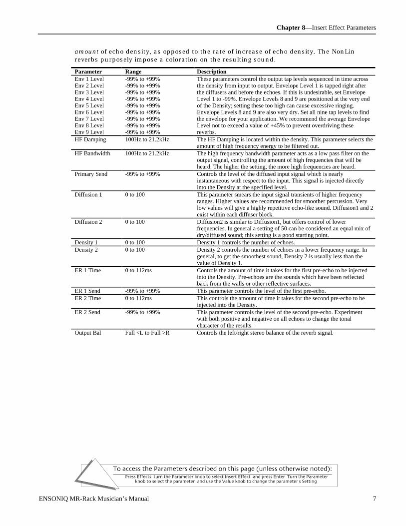
Chapter 8—Insert Effect Parameters
To access the Parameters described on this page (unless otherwise noted):Press Effects, turn the Parameter knob to select Insert Effect, and press Enter. Turn the Parameter
knob to select the parameter, and use the Value knob to change the parameter's Setting.
ENSONIQ MR-Rack Musician’s Manual 7
amount of echo density, as opposed to the rate of increase of echo density. The NonLinreverbs purposely impose a coloration on the resulting sound.
Parameter Range DescriptionEnv 1 LevelEnv 2 LevelEnv 3 LevelEnv 4 LevelEnv 5 LevelEnv 6 LevelEnv 7 LevelEnv 8 LevelEnv 9 Level
-99% to +99%-99% to +99%-99% to +99%-99% to +99%-99% to +99%-99% to +99%-99% to +99%-99% to +99%-99% to +99%
These parameters control the output tap levels sequenced in time acrossthe density from input to output. Envelope Level 1 is tapped right afterthe diffusers and before the echoes. If this is undesirable, set EnvelopeLevel 1 to -99%. Envelope Levels 8 and 9 are positioned at the very endof the Density; setting these too high can cause excessive ringing.Envelope Levels 8 and 9 are also very dry. Set all nine tap levels to findthe envelope for your application. We recommend the average EnvelopeLevel not to exceed a value of +45% to prevent overdriving thesereverbs.
HF Damping 100Hz to 21.2kHz The HF Damping is located within the density. This parameter selects theamount of high frequency energy to be filtered out.
HF Bandwidth 100Hz to 21.2kHz The high frequency bandwidth parameter acts as a low pass filter on theoutput signal, controlling the amount of high frequencies that will beheard. The higher the setting, the more high frequencies are heard.
Primary Send -99% to +99% Controls the level of the diffused input signal which is nearlyinstantaneous with respect to the input. This signal is injected directlyinto the Density at the specified level.
Diffusion 1 0 to 100 This parameter smears the input signal transients of higher frequencyranges. Higher values are recommended for smoother percussion. Verylow values will give a highly repetitive echo-like sound. Diffusion1 and 2exist within each diffuser block.
Diffusion 2 0 to 100 Diffusion2 is similar to Diffusion1, but offers control of lowerfrequencies. In general a setting of 50 can be considered an equal mix ofdry/diffused sound; this setting is a good starting point.
Density 1 0 to 100 Density 1 controls the number of echoes.Density 2 0 to 100 Density 2 controls the number of echoes in a lower frequency range. In
general, to get the smoothest sound, Density 2 is usually less than thevalue of Density 1.
ER 1 Time 0 to 112ms Controls the amount of time it takes for the first pre-echo to be injectedinto the Density. Pre-echoes are the sounds which have been reflectedback from the walls or other reflective surfaces.
ER 1 Send -99% to +99% This parameter controls the level of the first pre-echo.ER 2 Time 0 to 112ms This controls the amount of time it takes for the second pre-echo to be
injected into the Density.ER 2 Send -99% to +99% This parameter controls the level of the second pre-echo. Experiment
with both positive and negative on all echoes to change the tonalcharacter of the results.
Output Bal Full <L to Full >R Controls the left/right stereo balance of the reverb signal.

Chapter 8—Insert Effect Parameters
To access the Parameters described on this page (unless otherwise noted):Press Effects, turn the Parameter knob to select Insert Effect, and press Enter. Turn the Parameter
knob to select the parameter, and use the Value knob to change the parameter's Setting.
8 ENSONIQ MR-Rack Musician’s Manual
09 Gated ReverbWhen the output of a reverb is muted partway through its decay, it creates a gated sound.To achieve this gated effect, the Gated Reverb must gate a number of internal parameters,not just the output amplitude envelope. It is, however, the output amplitude over which youhave control. The MR-Rack offers a highly controllable gated reverb, optimized for percussiveinstruments, but useful for any sound. The gate is first opened when the input signal passesthe trigger threshold. This trigger threshold should be set as low as possible, so that none ofthe input signal is missed. The gated reverb triggers whenever the input signal exceeds a(user programmable) threshold. The gate will stay open as long as the input signal remainsabove the threshold, and all the input signals will be accumulated under this gate until thetotal input signal level falls below the hysteresis level. When this happens, the Hold Timewill begin. The reason for hysteresis is to eliminate false retriggering and to ensure precisehold time durations. If you desire a separate gate on each and every note, use the Non Linreverbs.
Parameter Range DescriptionGate Thresh -96.0dB to 0.0dB Sets the signal level that triggers the gated reverb. When the incoming
signal reaches this value, it triggers (starts) the gated reverb. Highervalues would require a stronger incoming signal. Set this parameter aslow as possible to work with your particular source, but not so low as tocause false triggering.
Gate Hysteresis 0dB to 48dB Sets the lower threshold level relative to Gate Thresh below which theGate Hold Time begins.If the difference between Gate Thresh and Gate Hysteresis is lower thanthe level of the incoming signal, the gated reverb will continue toretrigger. With a high Decay rate, this adds a cavernous quality topercussion instruments.
Gate Attack 50us to 10.0s Sets the attack time of the gated reverb once the incoming signal hasreached the trigger level. Generally the attack should be short and not setlonger than the Gate Hold time.
Gate Release 50us to 10.0s Sets the amount of time after the Gate Hold time has elapsed for thegated reverb to shut down. Generally these times are very short.
Gate Hold 50us to 10.0s Sets the amount of time that the reverb will hold after the retrigger andbefore the release. The Gate Hold time will begin again if retriggered.
Decay 0sec to 10.0sec Sets the decay rate. In general, the decay rate is set very high.HF Damping 100Hz to 21.2kHz Controls the rate of attenuation of high frequencies in the decay of the
reverb. Increasing the value of this parameter will gradually filter outincreasing amounts of high frequency energy.
Diffusion 1 0 to 100 Smears the transients, so as to diffuse and smooth the sound. Lowervalues will cause impulsive sounds to appear as a series of discreteechoes, while higher values tend to increase the smear (smoothersounding). Recommended setting is approximately 50.
Diffusion 2 0 to 100 This parameter, similar to and in series with Diffusion 1, performs thesame way but controls lower frequency ranges. Recommended setting isapproximately 50.
Definition 0 to 100 Controls the rate of echo density build up in the reverb decay. If set toohigh, the echo density will build at a rate that exceeds the decay rate. Ageneral rule of thumb: Definition should not exceed the Decay Rate. Werecommend settings between 25 and 50.
Slap Time 0ms to 108ms Controls the delay time of an internal dry stereo signal to create aslapback. In general, the slapback is greater or equal to the Gate Holdtime to achieve a reverse effect.
Slap Level Off, -49.5dB to +12.0dB Adjusts the volume of the slapback (internal dry) signal.
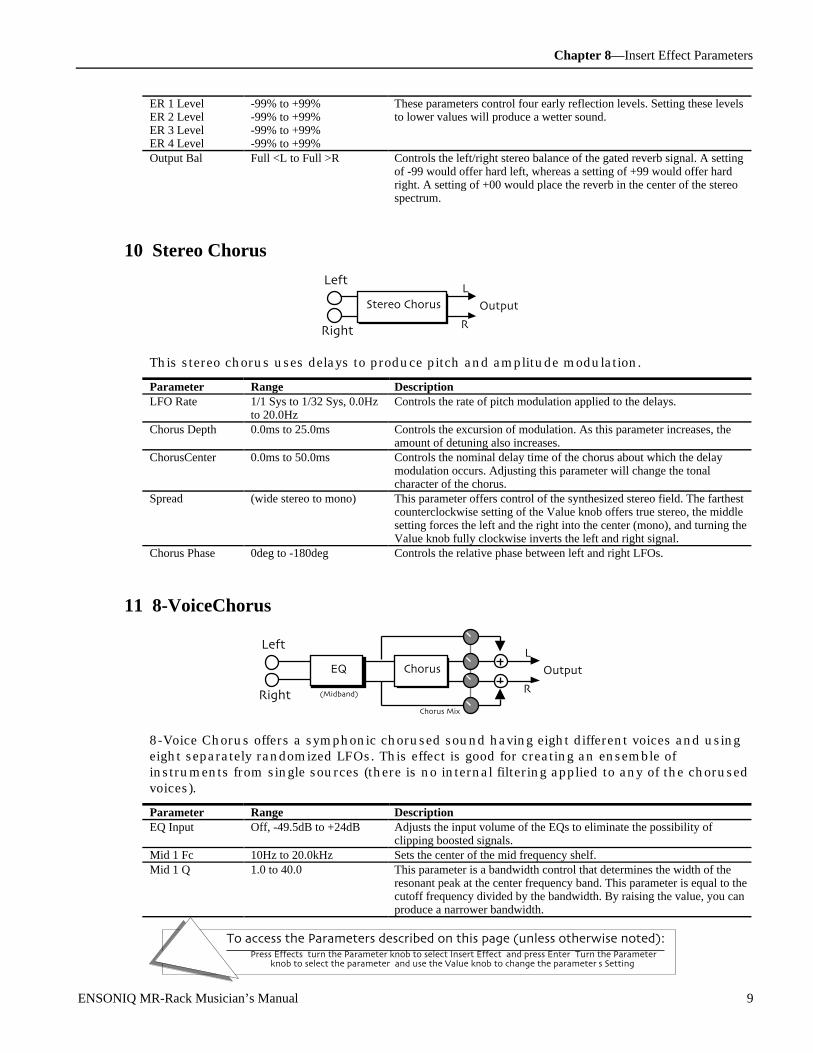
Chapter 8—Insert Effect Parameters
To access the Parameters described on this page (unless otherwise noted):Press Effects, turn the Parameter knob to select Insert Effect, and press Enter. Turn the Parameter
knob to select the parameter, and use the Value knob to change the parameter's Setting.
ENSONIQ MR-Rack Musician’s Manual 9
ER 1 LevelER 2 LevelER 3 LevelER 4 Level
-99% to +99%-99% to +99%-99% to +99%-99% to +99%
These parameters control four early reflection levels. Setting these levelsto lower values will produce a wetter sound.
Output Bal Full <L to Full >R Controls the left/right stereo balance of the gated reverb signal. A settingof -99 would offer hard left, whereas a setting of +99 would offer hardright. A setting of +00 would place the reverb in the center of the stereospectrum.
10 Stereo Chorus
Right
Left
Output
L
R
Stereo Chorus
This stereo chorus uses delays to produce pitch and amplitude modulation.
Parameter Range DescriptionLFO Rate 1/1 Sys to 1/32 Sys, 0.0Hz
to 20.0HzControls the rate of pitch modulation applied to the delays.
Chorus Depth 0.0ms to 25.0ms Controls the excursion of modulation. As this parameter increases, theamount of detuning also increases.
ChorusCenter 0.0ms to 50.0ms Controls the nominal delay time of the chorus about which the delaymodulation occurs. Adjusting this parameter will change the tonalcharacter of the chorus.
Spread (wide stereo to mono) This parameter offers control of the synthesized stereo field. The farthestcounterclockwise setting of the Value knob offers true stereo, the middlesetting forces the left and the right into the center (mono), and turning theValue knob fully clockwise inverts the left and right signal.
Chorus Phase 0deg to -180deg Controls the relative phase between left and right LFOs.
11 8-VoiceChorus
Right
Left
Chorus Mix
Output
L
R
ChorusEQ
(Midband)
8-Voice Chorus offers a symphonic chorused sound having eight different voices and usingeight separately randomized LFOs. This effect is good for creating an ensemble ofinstruments from single sources (there is no internal filtering applied to any of the chorusedvoices).
Parameter Range DescriptionEQ Input Off, -49.5dB to +24dB Adjusts the input volume of the EQs to eliminate the possibility of
clipping boosted signals.Mid 1 Fc 10Hz to 20.0kHz Sets the center of the mid frequency shelf.Mid 1 Q 1.0 to 40.0 This parameter is a bandwidth control that determines the width of the
resonant peak at the center frequency band. This parameter is equal to thecutoff frequency divided by the bandwidth. By raising the value, you canproduce a narrower bandwidth.
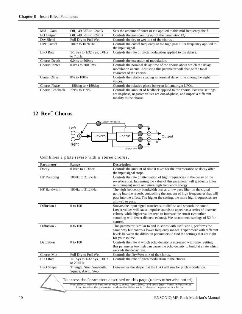
Chapter 8—Insert Effect Parameters
To access the Parameters described on this page (unless otherwise noted):Press Effects, turn the Parameter knob to select Insert Effect, and press Enter. Turn the Parameter
knob to select the parameter, and use the Value knob to change the parameter's Setting.
10 ENSONIQ MR-Rack Musician’s Manual
Mid 1 Gain Off, -49.5dB to +24dB Sets the amount of boost or cut applied to this mid frequency shelf.EQ Output Off, -49.5dB to +24dB Controls the gain coming out of the parametric EQ.Dry Blend Full Dry to Full Wet Controls the dry to wet mix of the chorus .HPF Cutoff 10Hz to 10.9kHz Controls the cutoff frequency of the high pass filter frequency applied to
the input signal.LFO Rate 1/1 Sys to 1/32 Sys, 0.0Hz
to 7.0HzControls the rate of pitch modulation applied to the delays.
Chorus Depth 0.0ms to 300ms Controls the excursion of modulation.ChorusCenter 0.0ms to 300.0ms Controls the nominal delay time of the chorus about which the delay
modulation occurs. Adjusting this parameter will change the tonalcharacter of the chorus.
Center Offset 0% to 100% Controls the relative spacing in nominal delay time among the eightvoices.
Chorus Phase -180deg to +180deg Controls the relative phase between left and right LFOs.Chorus Feedback -99% to +99% Controls the amount of feedback applied to the chorus. Positive settings
are in-phase, negative values are out-of-phase, and impart a differenttonality to the chorus.
12 Rev→Chorus
Chorus Mix
Output
L
R
Chorus
Right
Left
Reverb
System Feedback
Combines a plate reverb with a stereo chorus.
Parameter Range DescriptionDecay 0.0sec to 10.0sec Controls the amount of time it takes for the reverberation to decay after
the input signal stops.HF Damping 100Hz to 21.2kHz Controls the rate of attenuation of high frequencies in the decay of the
reverberation. Increasing the value of this parameter will gradually filterout (dampen) more and more high frequency energy.
HF Bandwidth 100Hz to 21.2kHz The high frequency bandwidth acts as a low pass filter on the signalgoing into the reverb, controlling the amount of high frequencies that willpass into the effect. The higher the setting, the more high frequencies areallowed to pass.
Diffusion 1 0 to 100 Smears the input signal transients, to diffuse and smooth the sound.Lower values will cause impulse sounds to appear as a series of discreteechoes, while higher values tend to increase the smear (smoothersounding with fewer discrete echoes). We recommend settings of 50 forstarters.
Diffusion 2 0 to 100 This parameter, similar to and in series with Diffusion1, performs thesame way but controls lower frequency ranges. Experiment with differentlevels between the diffusion parameters to find the settings that are rightfor your source.
Definition 0 to 100 Controls the rate at which echo density is increased with time. Settingthis parameter too high can cause the echo density to build at a rate whichexceeds the decay rate.
Chorus Mix Full Dry to Full Wet Controls the Dry/Wet mix of the chorus.LFO Rate 1/1 Sys to 1/32 Sys, 0.0Hz
to 20.0HzControls the rate of pitch modulation to the chorus.
LFO Shape Triangle, Sine, Sawtooth,Square, Asym, Step
Determines the shape that the LFO will use for pitch modulation.

Chapter 8—Insert Effect Parameters
To access the Parameters described on this page (unless otherwise noted):Press Effects, turn the Parameter knob to select Insert Effect, and press Enter. Turn the Parameter
knob to select the parameter, and use the Value knob to change the parameter's Setting.
ENSONIQ MR-Rack Musician’s Manual 11
LFO Phase -180deg to +180deg Controls the relative phase between left & right LFOs.Chorus Depth 0.0ms to 25.0ms Controls the amount of modulation.Chorus Center 0.0ms to 50.0ms Controls the delay times within the chorus. Adjusting this parameter will
change the tonal character of the chorus.System Feedback -99% to +99% Controls the amount of feedback applied from the output of the chorus to
the input of the reverb.
13 Rev→Flanger
Flanger Mix
Output
L
R
Flanger
Right
Left
Reverb
System Feedback
This Insert Effect features a plate reverb with a flanger effect.
Parameter Range DescriptionDecay 0.0sec to 10.0sec Controls the amount of time it takes for the reverb to decay after the input
signal stops.HF Damping 100Hz to 21.2kHz Controls the rate of attenuation of high frequencies in the decay of the
reverberation. Increasing the value of this parameter will gradually filterout (dampen) more and more high frequency energy.
HF Bandwidth 100Hz to 21.2kHz The high frequency bandwidth acts as a low pass filter on the signalgoing into the reverb, controlling the amount of high frequencies that willpass into the effect. The higher the setting, the more high frequencies areallowed to pass.
Diffusion 1 0 to 100 Smears the input signal transients, to diffuse and smooth the sound.Lower values will cause impulse sounds to appear as a series of discreteechoes, while higher values tend to increase the smear (smoothersounding with fewer discrete echoes). We recommend settings of 50 forstarters.
Diffusion 2 0 to 100 This parameter, similar to and in series with Diffusion1, performs thesame way but controls lower frequency ranges. Experiment with differentlevels between the diffusion parameters to find the settings that are rightfor your source.
Definition 0 to 100 Controls the rate at which echo density is increased with time. Settingthis parameter too high can cause the echo density to build at a rate whichexceeds the decay rate.
FlangerMix Full Dry to Full Wet Controls the Dry/Wet mix of the flanger.LFO Rate 1/1 Sys to 1/32 Sys, 0.0Hz
to 20.0HzControls the rate of modulation applied to the flanger.
LFO Shape Triangle, Sine, Sawtooth,Square, Asym, Step
Determines the shape that the LFO will use for pitch modulation.
LFO Phase -180deg to +180deg Controls the relative phase between left and right LFOs.Flanger Depth 0.0ms to 25.0ms Controls the range of the high-to-low frequency sweep in the flanger
effect.FlangerCenter 0.0ms to 50.0ms Sets the sweep mid-point of the flanger effect.Notch Depth 0% to 100% Controls the depth of the peaks and notches produced by the flanger.Feedback -99% to +99% Controls the amount of feedback applied to the flanger. Positive or
negative values will impart a different tonality to the flange effect, eitheraccenting the peaks or the notches.
System Feedback -99% to +99% Controls the amount of feedback applied from the output of the flanger tothe input of the reverb.

Chapter 8—Insert Effect Parameters
To access the Parameters described on this page (unless otherwise noted):Press Effects, turn the Parameter knob to select Insert Effect, and press Enter. Turn the Parameter
knob to select the parameter, and use the Value knob to change the parameter's Setting.
12 ENSONIQ MR-Rack Musician’s Manual
14 Rev→Phaser
Phaser Mix
Output
L
R
PhaserReverb
Right
Left
Combines a plate reverb with a 12-pole phase shifter.
Parameter Range DescriptionDecay 0.0sec to 10.0sec Controls the amount of time it takes for the reverberation to decay away
to a very low level after the input signal stops.HF Damping 100Hz to 21.2kHz Controls the rate of attenuation of high frequencies in the decay of the
reverberation. As natural reverb decays, some high frequencies tend toget absorbed by the environment. Increasing the value of this parameterwill gradually filter out (dampen) more and more high frequency energy.
HF Bandwidth 100Hz to 21.2kHz The high frequency bandwidth acts as a low pass filter on the signalgoing into the reverb, controlling the amount of high frequencies that willpass into the effect. The higher the setting, the more high frequencies areallowed to pass. This functions like a tone control on a guitar.
Diffusion 1 0 to 100 Smears the input signal transients, to diffuse and smooth the sound.Lower values will cause impulse sounds to appear as a series of discreteechoes, while higher values tend to increase the smear (smoothersounding with fewer discrete echoes). We recommend settings of 50 forstarters.
Diffusion 2 0 to 100 This parameter, similar to and in series with Diffusion1, performs thesame way but controls lower frequency ranges. Experiment with differentlevels between the diffusion parameters to find the settings that are rightfor your source.
Definition 0 to 100 Controls the rate at which echo density is increased with time. Settingthis parameter too high can cause the echo density to build at a rate whichexceeds the decay rate.
Phaser Mix Full Dry to Full Wet Controls the Dry/Wet mix of the phaser.LFO Rate 1/1 Sys to 1/32 Sys, 0.0Hz
to 20.0HzControls the rate of the modulation applied to the phaser.
LFO Shape Triangle, Sine, Sawtooth,Square, Asym, Step
Determines the shape that the LFO will use for pitch modulation.
Phaser Depth 0 to 100 Controls the amount of modulation applied to the phaser.Phaser Center 0 to 100 This parameter controls the mid-point of the phaser.Notch Depth 0% to 100% Controls the depth of the peaks and notches produced by the phaser. This
parameter should normally be set to 100%.Feedback -99% to +99% Controls the amount of feedback applied to the phaser. Positive or
negative values will impart a different tonality to the phaser effect, eitheraccenting the peaks or the notches.
15 Chorus→Rev
Reverb Mix
Output
L
RRight
Left
Stereo Chorus Reverb
Chorus→Rev combines a rich sounding chorus with the standard reverb.
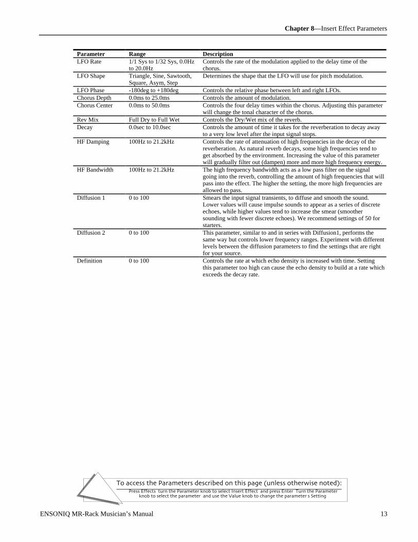
Chapter 8—Insert Effect Parameters
To access the Parameters described on this page (unless otherwise noted):Press Effects, turn the Parameter knob to select Insert Effect, and press Enter. Turn the Parameter
knob to select the parameter, and use the Value knob to change the parameter's Setting.
ENSONIQ MR-Rack Musician’s Manual 13
Parameter Range DescriptionLFO Rate 1/1 Sys to 1/32 Sys, 0.0Hz
to 20.0HzControls the rate of the modulation applied to the delay time of thechorus.
LFO Shape Triangle, Sine, Sawtooth,Square, Asym, Step
Determines the shape that the LFO will use for pitch modulation.
LFO Phase -180deg to +180deg Controls the relative phase between left and right LFOs.Chorus Depth 0.0ms to 25.0ms Controls the amount of modulation.Chorus Center 0.0ms to 50.0ms Controls the four delay times within the chorus. Adjusting this parameter
will change the tonal character of the chorus.Rev Mix Full Dry to Full Wet Controls the Dry/Wet mix of the reverb.Decay 0.0sec to 10.0sec Controls the amount of time it takes for the reverberation to decay away
to a very low level after the input signal stops.HF Damping 100Hz to 21.2kHz Controls the rate of attenuation of high frequencies in the decay of the
reverberation. As natural reverb decays, some high frequencies tend toget absorbed by the environment. Increasing the value of this parameterwill gradually filter out (dampen) more and more high frequency energy.
HF Bandwidth 100Hz to 21.2kHz The high frequency bandwidth acts as a low pass filter on the signalgoing into the reverb, controlling the amount of high frequencies that willpass into the effect. The higher the setting, the more high frequencies areallowed to pass.
Diffusion 1 0 to 100 Smears the input signal transients, to diffuse and smooth the sound.Lower values will cause impulse sounds to appear as a series of discreteechoes, while higher values tend to increase the smear (smoothersounding with fewer discrete echoes). We recommend settings of 50 forstarters.
Diffusion 2 0 to 100 This parameter, similar to and in series with Diffusion1, performs thesame way but controls lower frequency ranges. Experiment with differentlevels between the diffusion parameters to find the settings that are rightfor your source.
Definition 0 to 100 Controls the rate at which echo density is increased with time. Settingthis parameter too high can cause the echo density to build at a rate whichexceeds the decay rate.

Chapter 8—Insert Effect Parameters
To access the Parameters described on this page (unless otherwise noted):Press Effects, turn the Parameter knob to select Insert Effect, and press Enter. Turn the Parameter
knob to select the parameter, and use the Value knob to change the parameter's Setting.
14 ENSONIQ MR-Rack Musician’s Manual
16 Flanger→Rev
Left
Reverb Mix
Output
L
RRight
Stereo Flanger Reverb
This Insert Effect features a flanger combined with a plate reverb.
Parameter Range DescriptionLFO Rate 1/1 Sys to 1/32 Sys, 0.0Hz
to 20.0HzControls the rate of the modulation applied to the flange effect.
LFO Shape Triangle, Sine, Sawtooth,Square, Asym, Step
Determines the shape that the LFO will use for pitch modulation.
LFO Phase -180deg to +180deg Controls the relative phase between left and right LFOs.Flanger Depth 0.0ms to 25.0ms Controls the range of the high-to-low frequency sweep in the flanger
effect.FlangerCenter 0.0ms to 50.0ms Sets the sweep mid-point of the flanger effect.Notch Depth 0% to 100% Controls the depth of the peaks and notches produced by the flanger. This
parameter should be set to 100% for maximum effect.Feedback -99% to +99% Controls the amount of feedback applied to the flanger. Positive or
negative values will impart a different tonality to the flange effect, eitheraccenting the peaks or the notches.
Rev Mix Full Dry to Full Wet Controls the Dry/Wet mix of the reverb.Decay 0.0sec to 10.0sec Controls the amount of time it takes for the reverberation to decay away
to a very low level after the input signal stops.HF Damping 100Hz to 21.2kHz Controls the rate of attenuation of high frequencies in the decay of the
reverberation. As natural reverb decays, some high frequencies tend toget absorbed by the environment. Increasing the value of this parameterwill gradually filter out (dampen) more and more high frequency energy.
HF Bandwidth 100Hz to 21.2kHz The high frequency bandwidth acts as a low pass filter on the signalgoing into the reverb, controlling the amount of high frequencies that willpass into the effect. The higher the setting, the more high frequencies areallowed to pass.
Diffusion 1 0 to 100 Smears the input signal transients, to diffuse and smooth the sound.Lower values will cause impulse sounds to appear as a series of discreteechoes, while higher values tend to increase the smear (smoothersounding with fewer discrete echoes). We recommend settings of 50 forstarters.
Diffusion 2 0 to 100 This parameter, similar to and in series with Diffusion1, performs thesame way but controls lower frequency ranges. Experiment with differentlevels between the diffusion parameters to find the settings that are rightfor your source.
Definition 0 to 100 Controls the rate at which echo density is increased with time. Settingthis parameter too high can cause the echo density to build at a rate whichexceeds the decay rate.

Chapter 8—Insert Effect Parameters
To access the Parameters described on this page (unless otherwise noted):Press Effects, turn the Parameter knob to select Insert Effect, and press Enter. Turn the Parameter
knob to select the parameter, and use the Value knob to change the parameter's Setting.
ENSONIQ MR-Rack Musician’s Manual 15
17 Phaser→Rev
Left
Reverb Mix
Output
L
RRight
Stereo Phaser Reverb
A 12-pole phase shifter with reverb.
Parameter Range DescriptionLFO Rate 1/1 Sys to 1/32 Sys, 0.0Hz
to 20.0HzControls the rate of the modulation applied to the phaser.
LFO Shape Triangle, Sine, Sawtooth,Square, Asym, Step
Determines the shape that the LFO will use for pitch modulation.
Phaser Depth 0 to 100 Controls the amount of modulation applied to the phaser.Phaser Center 0 to 100 This parameter controls the mid-point of the phaser.Notch Depth 0% to 100% Controls the depth of the peaks and notches produced by the phaser. This
parameter should normally be set to 99.Feedback -99% to +99% Controls the amount of feedback applied to the phaser. Positive or
negative values will impart a different tonality to the phaser effect, eitheraccenting the peaks or the notches.
Rev Mix Full Dry to Full Wet Controls the Dry/Wet mix of the reverb.Decay 0.0sec to 10.0sec Controls the amount of time it takes for the reverberation to decay away
to a very low level after the input signal stops.HF Damping 100Hz to 21.2kHz Controls the rate of attenuation of high frequencies in the decay of the
reverberation. As natural reverb decays, some high frequencies tend toget absorbed by the environment. Increasing the value of this parameterwill gradually filter out (dampen) more and more high frequency energy.
HF Bandwidth 100Hz to 21.2kHz The high frequency bandwidth acts as a low pass filter on the signalgoing into the reverb, controlling the amount of high frequencies that willpass into the effect. The higher the setting, the more high frequencies areallowed to pass. This functions like a tone control on a guitar.
Diffusion 1 0 to 100 Smears the input signal transients, to diffuse and smooth the sound.Lower values will cause impulse sounds to appear as a series of discreteechoes, while higher values tend to increase the smear (smoothersounding with fewer discrete echoes). We recommend settings of 50 forstarters.
Diffusion 2 0 to 100 This parameter, similar to and in series with Diffusion1, performs thesame way but controls lower frequency ranges. Experiment with differentlevels between the diffusion parameters to find the settings that are rightfor your source.
Definition 0 to 100 Controls the rate at which echo density is increased with time. Settingthis parameter too high can cause the echo density to build at a rate whichexceeds the decay rate.

Chapter 8—Insert Effect Parameters
To access the Parameters described on this page (unless otherwise noted):Press Effects, turn the Parameter knob to select Insert Effect, and press Enter. Turn the Parameter
knob to select the parameter, and use the Value knob to change the parameter's Setting.
16 ENSONIQ MR-Rack Musician’s Manual
18 EQ→Reverb
Reverb Mix
Output
L
RRight
Left
ReverbLo Shelf Mid Hi Shelf
EQ Input
A parametric EQ with reverb.
Parameter Range DescriptionEQ Input Off, -49.5dB to +24dB Adjusts the input level trim to the EQs to eliminate the possibility of
clipping boosted signals.LoShelf Fc 10Hz to 20.0kHz Sets the center of the low frequency EQ.LoShelf Gain Off, -49.5dB to +24dB Sets the amount of boost or cut applied to this low frequency shelf.Mid 1 Fc 10Hz to 20.0kHz Sets the center of the mid frequency parametric.Mid 1 Q 1.0 to 40.0 This parameter is a bandwidth control that determines the width of the
resonant peak at the center frequency band. This parameter is equal to thecutoff frequency divided by the bandwidth. By raising the value, you canproduce a narrower bandwidth.
Mid 1 Gain Off, -49.5dB to +24dB Sets the amount of boost or cut applied to this high frequency shelf.HiShelf Fc 10Hz to 20.0kHz Sets the center frequency of the high frequency shelf.HiShelf Gain Off, -49.5dB to +24dB Sets the amount of boost or cut applied to this shelf.EQ Output Off, -49.5dB to +24dB Controls the gain coming out of the parametric EQ.Rev Mix Full Dry to Full Wet Controls the reverb mix.Decay 0.0sec to 10.0sec Controls the amount of time it takes for the reverb to decay after the input
signal stops.HF Damping 100Hz to 21.2kHz Controls the rate of attenuation of high frequencies in the decay of the
reverb. Increasing the value of this parameter will gradually filter out(dampen) more and more high frequency energy.
HF Bandwidth 100Hz to 21.2kHz Acts as a low pass filter on the signal going into the reverb, controlling theamount of high frequencies that will pass. The higher the setting, the morehigh frequencies are allowed to pass.
Diffusion 1 0 to 100 Smears the input signal transients, to diffuse and smooth the sound. Lowervalues will cause impulse sounds to appear as a series of discrete echoes,while higher values tend to increase the smear (smoother sounding withfewer discrete echoes). We recommend settings of 50 for starters.
Diffusion 2 0 to 100 This parameter, similar to and in series with Diffusion1, controls lowerfrequency ranges.
Definition 0 to 100 Controls the rate at which echo density is increased with time. Setting thistoo high can cause the echo density to build at a rate which exceeds thedecay rate.

Chapter 8—Insert Effect Parameters
To access the Parameters described on this page (unless otherwise noted):Press Effects, turn the Parameter knob to select Insert Effect, and press Enter. Turn the Parameter
knob to select the parameter, and use the Value knob to change the parameter's Setting.
ENSONIQ MR-Rack Musician’s Manual 17
19 Spinner→Rev
DDL LPF
DDL LPF
Gain Center
Gain Center
L/R LFO
F/B LFO
+ + + +
- - --
Cancellation
Reverb Mix
Output
L
R
Reverb
Right
Left
Combines a pseudo-three dimensional panner with the standard reverb.
Parameter Range DescriptionLFO Rate 1/1 Sys to 1/32 Sys, 0.0Hz
to 20.0HzControls the rate of modulation applied to the spinner.
LFO Shape Triangle, Sine, Sawtooth,Square, Asym, Step
Determines the shape that the LFO will use for modulation.
LFO Phase -180deg to +180deg Controls the relative phase between the left and right and front and backLFOs. Set this to ±90 deg for circular motion.
DDL Mod Depth 0.0ms to 10.0ms Controls the left to right mod depth to delay time. Try setting this to 0.3ms for average head size.
DDL ModCenter 0.0ms to 50.0ms Fixed delay time.Level Mod 0% to 100% Left to right LFO mod depth to level.L-to-R Mod 0% to 100% Left to right LFO mod depth to filter.F-to-B Mod 0% to 100% Front to back LFO mod depth to filter. If the sum of the L-to-R Mod and
F-to-B Mod is greater than 100%, the filter can “thump” as it closesdown.
Cancellation -99% to +99% Sets the depth and phase of the opposite speaker cancellation signal.Rev Mix Full Dry to Full Wet Controls the Dry/Wet mix of the reverb.Decay 0.0sec to 10.0sec Controls the amount of time it takes for the reverb to decay after the input
signal stops.HF Damping 100Hz to 21.2kHz Controls the rate of attenuation of high frequencies in the decay of the
reverberation. Increasing the value of this parameter will gradually filterout (dampen) more and more high frequency energy.
HF Bandwidth 100Hz to 21.2kHz Acts as a low pass filter on the signal going into the reverb, controllingthe amount of high frequencies that will pass. The higher the setting, themore high frequencies are allowed to pass.
Diffusion 1 0 to 100 Smears the input signal transients, to diffuse and smooth the sound.Lower values will cause impulse sounds to appear as a series of discreteechoes, while higher values tend to increase the smear (smoothersounding with fewer discrete echoes). We recommend settings of 50 forstarters.
Diffusion 2 0 to 100 This parameter, similar to and in series with Diffusion1, controls lowerfrequency ranges.
Definition 0 to 100 Controls the rate at which echo density is increased with time. Settingthis too high can cause the echo density to build at a rate which exceedsthe decay rate.

Chapter 8—Insert Effect Parameters
To access the Parameters described on this page (unless otherwise noted):Press Effects, turn the Parameter knob to select Insert Effect, and press Enter. Turn the Parameter
knob to select the parameter, and use the Value knob to change the parameter's Setting.
18 ENSONIQ MR-Rack Musician’s Manual
20 DDL→Chorus
4-Tap DDL
Right
Left
OutputChorus
L
R
DDL→Chorus combines four independent controllable digital delays with a chorus.
Parameter Range DescriptionDly1 Time 1/1 Sys to 1/32 Sys, 0ms to
630msSets the amount of delay time for the first independent delay.
Dly1 Level Off, -49.5dB to +12.0dB Adjusts the volume of the delayed signal against the original dry signal.Dly1 Feedback -99% to +99% Determines the amount of signal that will be fed from the output back
into the input, increasing the number of repeats in the delay.Dly1 Damping 100Hz to 21.2kHz Controls the cutoff of a low pass filter on the feedback signal, which
adjusts the amount of damping to the feedback signals. The higher thenumber, the more the signals are damped.
Dly1 Pan Full <L to Full >R Determines the location of the delay in the stereo spectrum.Dly2 Time 1/1 Sys to 1/32 Sys, 0ms to
630msSets the amount of delay time for the second independent delay.
Dly2 Level Off, -49.5dB to +12.0dB Adjusts the volume of the delayed signal against the original dry signal.Dly2 Feedback -99% to +99% Determines the amount of signal that will be fed from the output back
into the input, increasing the number of repeats in the delay.Dly2 Damping 100Hz to 21.2kHz Controls the cutoff of a low pass filter on the feedback signal, which
adjusts the amount of damping to the feedback signals. The higher thenumber, the more the signals are damped.
Dly2 Pan Full <L to Full >R Determines the location of the delay in the stereo spectrum.Dly3 Time 1/1 Sys to 1/32 Sys, 0ms to
630msSets the amount of delay time for the third independent delay.
Dly3 Level Off, -49.5dB to +12.0dB Adjusts the volume of the delayed signal against the original dry signal.Dly3 Pan Full <L to Full >R Determines the location of the delay in the stereo spectrum.Dly4 Time 1/1 Sys to 1/32 Sys, 0ms to
630msSets the amount of delay time for the fourth independent delay.
Dly4 Level Off, -49.5dB to +12.0dB Adjusts the volume of the delayed signal against the original dry signal.Dly4 Pan Full <L to Full >R Determines the location of the delay in the stereo spectrum.LFO Rate 1/1 Sys to 1/32 Sys, 0.0Hz
to 20.0HzControls the four rates of the modulation applied to the delay time of thechorus.
LFO Shape Triangle, Sine, Sawtooth,Square, Asym, Step
Determines the shape that the LFO will use for pitch modulation.
LFO Phase -180deg to +180deg Controls the relative phase between left and right LFOs.Chorus Depth 0.0ms to 25.0ms Controls the amount of modulation.ChorusCenter 0.0ms to 50.0ms Controls the delay time within the chorus, and changes the tonal
character.Spread (wide stereo to mono) This parameter offers control of the synthesized stereo field. The farthest
counterclockwise setting of the Value knob offers true stereo, the middlesetting forces the left and the right into the center (mono), and turning theValue knob fully clockwise inverts the left and right signal.
21 DDL→Flanger

Chapter 8—Insert Effect Parameters
To access the Parameters described on this page (unless otherwise noted):Press Effects, turn the Parameter knob to select Insert Effect, and press Enter. Turn the Parameter
knob to select the parameter, and use the Value knob to change the parameter's Setting.
ENSONIQ MR-Rack Musician’s Manual 19
4-Tap DDL
Right
Left
OutputFlanger
L
R
Combines four independent controllable digital delays with a flanger.
Parameter Range DescriptionDly1 Time 1/1 Sys to 1/32 Sys, 0ms to
630msSets the amount of delay time for the first independent delay.
Dly1 Level Off, -49.5dB to +12.0dB Adjusts the volume of the delayed signal against the original dry signal.Dly1 Feedback -99% to +99% Determines the amount of signal that will be fed from the output back
into the input, increasing the number of repeats in the delay.Dly1 Damping 100Hz to 21.2kHz Controls the cutoff of a low pass filter on the feedback signal, which
adjusts the amount of damping to the feedback signals. The higher thenumber, the more the signals are damped.
Dly1 Pan Full <L to Full >R Determines the location of the delay in the stereo spectrum.Dly2 Time 1/1 Sys to 1/32 Sys, 0ms to
630msSets the amount of delay time for the second independent delay.
Dly2 Level Off, -49.5dB to +12.0dB Adjusts the volume of the delayed signal against the original dry signal.Dly2 Feedback -99% to +99% Determines the amount of signal that will be fed from the output back
into the input, increasing the number of repeats in the delay.Dly2 Damping 100Hz to 21.2kHz Controls the cutoff of a low pass filter on the feedback signal, which
adjusts the amount of damping to the feedback signals. The higher thenumber, the more the signals are damped.
Dly2 Pan Full <L to Full >R Determines the location of the delay in the stereo spectrum.Dly3 Time 1/1 Sys to 1/32 Sys, 0ms to
630msSets the amount of delay time for the third independent delay.
Dly3 Level Off, -49.5dB to +12.0dB Adjusts the volume of the delayed signal against the original dry signal.Dly3 Pan Full <L to Full >R Determines the location of the delay in the stereo spectrum.Dly4 Time 1/1 Sys to 1/32 Sys, 0ms to
630msSets the amount of delay time for the fourth independent delay.
Dly4 Level Off, -49.5dB to +12.0dB Adjusts the volume of the delayed signal against the original dry signal.Dly4 Pan Full <L to Full >R Determines the location of the delay in the stereo spectrum.LFO Rate 1/1 Sys to 1/32 Sys, 0.0Hz
to 20.0HzControls the rate of the modulation applied to the flange effect.
LFO Shape Triangle, Sine, Sawtooth,Square, Asym, Step
Determines the shape that the LFO will use for pitch modulation.
LFO Phase -180deg to +180deg Controls the relative phase between left and right LFOs.Flanger Depth 0.0ms to 25.0ms Controls the range of the high-to-low frequency sweep in the flanger
effect.FlangerCenter 0.0ms to 50.0ms Sets the sweep mid-point of the flanger effect.Notch Depth 0% to 100% Controls the depth of the peaks and notches produced by the flanger. This
parameter should be set to 100% for maximum effect.Feedback -99% to +99% Controls the amount of feedback applied to the flanger. Positive or
negative values will impart a different tonality to the flange effect, eitheraccenting the peaks or the notches.
22 DDL→Phaser
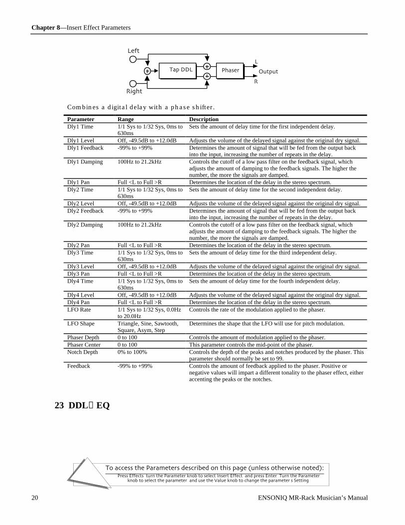
Chapter 8—Insert Effect Parameters
To access the Parameters described on this page (unless otherwise noted):Press Effects, turn the Parameter knob to select Insert Effect, and press Enter. Turn the Parameter
knob to select the parameter, and use the Value knob to change the parameter's Setting.
20 ENSONIQ MR-Rack Musician’s Manual
4-Tap DDL
Right
Left
OutputPhaser
L
R
Combines a digital delay with a phase shifter.
Parameter Range DescriptionDly1 Time 1/1 Sys to 1/32 Sys, 0ms to
630msSets the amount of delay time for the first independent delay.
Dly1 Level Off, -49.5dB to +12.0dB Adjusts the volume of the delayed signal against the original dry signal.Dly1 Feedback -99% to +99% Determines the amount of signal that will be fed from the output back
into the input, increasing the number of repeats in the delay.Dly1 Damping 100Hz to 21.2kHz Controls the cutoff of a low pass filter on the feedback signal, which
adjusts the amount of damping to the feedback signals. The higher thenumber, the more the signals are damped.
Dly1 Pan Full <L to Full >R Determines the location of the delay in the stereo spectrum.Dly2 Time 1/1 Sys to 1/32 Sys, 0ms to
630msSets the amount of delay time for the second independent delay.
Dly2 Level Off, -49.5dB to +12.0dB Adjusts the volume of the delayed signal against the original dry signal.Dly2 Feedback -99% to +99% Determines the amount of signal that will be fed from the output back
into the input, increasing the number of repeats in the delay.Dly2 Damping 100Hz to 21.2kHz Controls the cutoff of a low pass filter on the feedback signal, which
adjusts the amount of damping to the feedback signals. The higher thenumber, the more the signals are damped.
Dly2 Pan Full <L to Full >R Determines the location of the delay in the stereo spectrum.Dly3 Time 1/1 Sys to 1/32 Sys, 0ms to
630msSets the amount of delay time for the third independent delay.
Dly3 Level Off, -49.5dB to +12.0dB Adjusts the volume of the delayed signal against the original dry signal.Dly3 Pan Full <L to Full >R Determines the location of the delay in the stereo spectrum.Dly4 Time 1/1 Sys to 1/32 Sys, 0ms to
630msSets the amount of delay time for the fourth independent delay.
Dly4 Level Off, -49.5dB to +12.0dB Adjusts the volume of the delayed signal against the original dry signal.Dly4 Pan Full <L to Full >R Determines the location of the delay in the stereo spectrum.LFO Rate 1/1 Sys to 1/32 Sys, 0.0Hz
to 20.0HzControls the rate of the modulation applied to the phaser.
LFO Shape Triangle, Sine, Sawtooth,Square, Asym, Step
Determines the shape that the LFO will use for pitch modulation.
Phaser Depth 0 to 100 Controls the amount of modulation applied to the phaser.Phaser Center 0 to 100 This parameter controls the mid-point of the phaser.Notch Depth 0% to 100% Controls the depth of the peaks and notches produced by the phaser. This
parameter should normally be set to 99.Feedback -99% to +99% Controls the amount of feedback applied to the phaser. Positive or
negative values will impart a different tonality to the phaser effect, eitheraccenting the peaks or the notches.
23 DDL→EQ

Chapter 8—Insert Effect Parameters
To access the Parameters described on this page (unless otherwise noted):Press Effects, turn the Parameter knob to select Insert Effect, and press Enter. Turn the Parameter
knob to select the parameter, and use the Value knob to change the parameter's Setting.
ENSONIQ MR-Rack Musician’s Manual 21
Lo Shelf Mid
EQ Output
Hi Shelf4-Tap DDL
Right
Left
Output
L
R
Combines a digital delay with a parametric EQ.
Parameter Range DescriptionDly1 Time 1/1 Sys to 1/32 Sys, 0ms to
630msSets the amount of delay time for the first independent delay.
Dly1 Level Off, -49.5dB to +12.0dB Adjusts the volume of the delayed signal against the original dry signal.Dly1 Feedback -99% to +99% Determines the amount of signal that will be fed from the output back
into the input, increasing the number of repeats in the delay.Dly1 Damping 100Hz to 21.2kHz Controls the cutoff of a low pass filter on the feedback signal, which
adjusts the amount of damping to the feedback signals. The higher thenumber, the more the signals are damped.
Dly1 Pan Full <L to Full >R Determines the location of the delay in the stereo spectrum.Dly2 Time 1/1 Sys to 1/32 Sys, 0ms to
630msSets the amount of delay time for the second independent delay.
Dly2 Level Off, -49.5dB to +12.0dB Adjusts the volume of the delayed signal against the original dry signal.Dly2 Feedback -99% to +99% Determines the amount of signal that will be fed from the output back
into the input, increasing the number of repeats in the delay.Dly2 Damping 100Hz to 21.2kHz Controls the cutoff of a low pass filter on the feedback signal, which
adjusts the amount of damping to the feedback signals. The higher thenumber, the more the signals are damped.
Dly2 Pan Full <L to Full >R Determines the location of the delay in the stereo spectrum.Dly3 Time 1/1 Sys to 1/32 Sys, 0ms to
630msSets the amount of delay time for the third independent delay.
Dly3 Level Off, -49.5dB to +12.0dB Adjusts the volume of the delayed signal against the original dry signal.Dly3 Pan Full <L to Full >R Determines the location of the delay in the stereo spectrum.Dly4 Time 1/1 Sys to 1/32 Sys, 0ms to
630msSets the amount of delay time for the fourth independent delay.
Dly4 Level Off, -49.5dB to +12.0dB Adjusts the volume of the delayed signal against the original dry signal.Dly4 Pan Full <L to Full >R Determines the location of the delay in the stereo spectrum.EQ Input Off, -49.5dB to +24dB Adjusts the input level trim to the EQs to eliminate the possibility of
clipping boosted signals.LoShelf Fc 10Hz to 20.0kHz Sets the center of the low frequency EQ.LoShelf Gain Off, -49.5dB to +24dB Sets the amount of boost or cut applied to this low frequency shelf.Mid 1 Fc 10Hz to 20.0kHz Sets the center of the mid frequency parametric.Mid 1 Q 1.0 to 40.0 This parameter is a bandwidth control that determines the width of the
resonant peak at the center frequency band. This parameter is equal to thecutoff frequency divided by the bandwidth. By raising the value, you canproduce a narrower bandwidth.
Mid 1 Gain Off, -49.5dB to +24dB Sets the amount of boost or cut applied to this mid frequency shelf.HiShelf Fc 10Hz to 20.0kHz Sets the center frequency of the high frequency shelf.HiShelf Gain Off, -49.5dB to +24dB Sets the amount of boost or cut applied to this high frequency shelf.EQ Output Off, -49.5dB to +24dB Controls the gain coming out of the parametric EQ.
24 Multi-Tap DDL
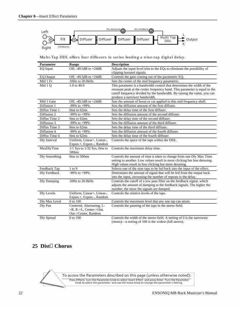
Chapter 8—Insert Effect Parameters
To access the Parameters described on this page (unless otherwise noted):Press Effects, turn the Parameter knob to select Insert Effect, and press Enter. Turn the Parameter
knob to select the parameter, and use the Value knob to change the parameter's Setting.
22 ENSONIQ MR-Rack Musician’s Manual
Right
Left
Diffuser 1 Output
L
R
Multi-TapDDL
EQ
(Midband)
Diffuser 2 Diffuser 3 Diffuser 4
Dly FeedbackDly Damping
Multi-Tap DDL offers four diffusers in series feeding a nine-tap digital delay.
Parameter Range DescriptionEQ Input Off, -49.5dB to +24dB Adjusts the input level trim to the EQs to eliminate the possibility of
clipping boosted signals.EQ Output Off, -49.5dB to +24dB Controls the gain coming out of the parametric EQ.Mid 1 Fc 10Hz to 20.0kHz Sets the center of the mid frequency parametric.Mid 1 Q 1.0 to 40.0 This parameter is a bandwidth control that determines the width of the
resonant peak at the center frequency band. This parameter is equal to thecutoff frequency divided by the bandwidth. By raising the value, you canproduce a narrower bandwidth.
Mid 1 Gain Off, -49.5dB to +24dB Sets the amount of boost or cut applied to this mid frequency shelf.Diffusion 1 -99% to +99% Sets the diffusion amount of the first diffuser.Diffus Time 1 0ms to 62ms Sets the delay time of the first diffuser.Diffusion 2 -99% to +99% Sets the diffusion amount of the second diffuser.Diffus Time 2 0ms to 62ms Sets the delay time of the second diffuser.Diffusion 3 -99% to +99% Sets the diffusion amount of the third diffuser.Diffus Time 3 0ms to 62ms Sets the delay time of the third diffuser.Diffusion 4 -99% to +99% Sets the diffusion amount of the fourth diffuser.Diffus Time 4 0ms to 62ms Sets the delay time of the fourth diffuser.Dly Interval Uniform, Linear+, Linear-,
Expon.+, Expon.-, RandomControls the space of the taps within the DDL.
MaxDlyTime 1/1 Sys to 1/32 Sys, 0ms to500ms
Controls the maximum delay time.
Dly Smoothing 0ms to 500ms Controls the amount of time it takes to change from one Dly Max Timesetting to another. Low values result in more clicking but less detuning.High values result in less clicking but more detuning.
Feedback Tap 1 to 9 Selects one of the nine taps to be fed back into the input of the effect.Dly Feedback -99% to +99% Determines the amount of signal that will be fed from the output back
into the input, increasing the number of repeats in the delay.Dly Damping 10Hz to 20.0kHz Controls the cutoff of a low pass filter on the feedback signal, which
adjusts the amount of damping to the feedback signals. The higher thenumber, the more the signals are damped.
Dly Levels Uniform, Linear+, Linear-,Expon.+, Expon.-, Random
Controls the relative levels of the taps.
Dly Max Level 0 to 100 Controls the maximum level that any one tap can attain.Dly Pan Centered, Alternating, L-
>R, R->L, Center->Out,Out->Center, Random
Controls the panning of the taps in the stereo field.
Dly Spread 0 to 100 Controls the width of the stereo field. A setting of 0 is the narrowest(mono)—a setting of 100 is the widest (full stereo).
25 Dist→Chorus

Chapter 8—Insert Effect Parameters
To access the Parameters described on this page (unless otherwise noted):Press Effects, turn the Parameter knob to select Insert Effect, and press Enter. Turn the Parameter
knob to select the parameter, and use the Value knob to change the parameter's Setting.
ENSONIQ MR-Rack Musician’s Manual 23
Distortion
Right
Left
Lo Shelf Mid 1 Mid 2 Hi Shelf Output
L
R
Chorus
Dist→Chorus combines a distortion with a chorus.
Parameter Range DescriptionDist LPF Fc 10Hz to 20.0kHz Filters out high frequencies prior to the distortion.Dist Offset -99% to +99% Adjusts the balance of even-to-odd-generated harmonics.Dist Gain Off, -49.5dB to +48dB Controls the gain going into the distortion effect. This will boost the
signal level up to 48 dB. For more distortion, use a high input level gainand turn the Dist Volume down to keep the volume under control. Forless distortion, use a low gain input level and a higher output volume.
Dist Curve Soft, Medium 1, Medium2, Hard, Buzz
Selects the type of clipping produced by the distortion. The curves rangefrom tube-like distortion (Soft) to nasty distortion (Buzz).
Dist Volume Off, -49.5dB to 0.0dB Controls the volume of the distortion effect. Generally, if the DistortionGain is set high, set this parameter lower.
Post VCF Fc 10Hz to 7.10kHz Determines the distortion filter cut off frequency. Higher values have abrighter sound. This parameter can be modulated, using a CV Pedal fora wah wah pedal effect.
Post VCF Q 1.0 to 40.0 Determines the level and width of the resonant peak at the filter cutoffpoint. While the Fc (filter cutoff) parameter determines where (at whatfrequency) this peak will occur, the Q setting controls the presence ofthe peak. This setting is important for the auto-wah effect.
Dist Dry Lev Off, -49.5dB to 0.0dB Controls the amount of dry signal to be mixed with the distorted signal.EQ Input Off, -49.5dB to +24dB Adjusts the input level trim to the EQs to eliminate the possibility of
clipping boosted signals.LoShelf Fc 10Hz to 20.0kHz Sets the center of the low frequency EQ.LoShelf Gain Off, -49.5dB to +24dB Sets the amount of boost or cut applied to this low frequency shelf.Mid 1 Fc 10Hz to 20.0kHz Sets the center of the mid frequency parametric.Mid 1 Q 1.0 to 40.0 This parameter is a bandwidth control that determines the width of the
resonant peak at the center frequency band. This parameter is equal tothe cutoff frequency divided by the bandwidth. By raising the value, youcan produce a narrower bandwidth.
Mid 1 Gain Off, -49.5dB to +24dB Sets the amount of boost or cut applied to this mid frequency shelf.Mid 2 Fc 10Hz to 20.0kHz Identical to the Mid 1 Fc parameter, and is used to control different
bandwidths within the mid range.Mid 2 Q 1.0 to 40.0 Identical to the Mid 1 Q parameter, and is used to control different
bandwidths within the mid range.Mid 2 Gain Off, -49.5dB to +24dB Identical to the Mid 1 Gain parameter, and is used to control different
bandwidths within the mid range.HiShelf Fc 10Hz to 20.0kHz Sets the center frequency of the high frequency shelf.HiShelf Gain Off, -49.5dB to +24dB Sets the amount of boost or cut applied to this high frequency shelf.EQ Output Off, -49.5dB to +24dB Controls the gain coming out of the parametric EQ.LFO Rate 1/1 Sys to 1/32 Sys, 0.0Hz
to 20.0HzControls the four rates of the modulation applied to the delay time of thechorus.
LFO Shape Triangle, Sine, Sawtooth,Square, Asym, Step
Determines the shape that the LFO will use for pitch modulation.
LFO Phase -180deg to +180deg Controls the relative phase between left and right LFOs.Chorus Depth 0.0ms to 25.0ms Controls the amount of modulation.ChorusCenter 0.0ms to 50.0ms Controls the delay times within the chorus. Adjusting this parameter
will change the tonal character of the chorus.
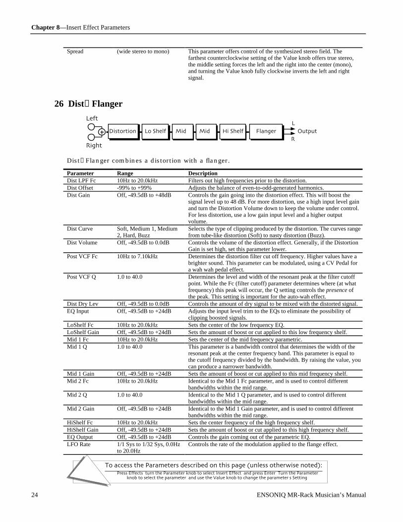
Chapter 8—Insert Effect Parameters
To access the Parameters described on this page (unless otherwise noted):Press Effects, turn the Parameter knob to select Insert Effect, and press Enter. Turn the Parameter
knob to select the parameter, and use the Value knob to change the parameter's Setting.
24 ENSONIQ MR-Rack Musician’s Manual
Spread (wide stereo to mono) This parameter offers control of the synthesized stereo field. Thefarthest counterclockwise setting of the Value knob offers true stereo,the middle setting forces the left and the right into the center (mono),and turning the Value knob fully clockwise inverts the left and rightsignal.
26 Dist→Flanger
Distortion
Right
Left
Lo Shelf Mid 1 Mid 2 Hi Shelf Output
L
R
Flanger
Dist→Flanger combines a distortion with a flanger.
Parameter Range DescriptionDist LPF Fc 10Hz to 20.0kHz Filters out high frequencies prior to the distortion.Dist Offset -99% to +99% Adjusts the balance of even-to-odd-generated harmonics.Dist Gain Off, -49.5dB to +48dB Controls the gain going into the distortion effect. This will boost the
signal level up to 48 dB. For more distortion, use a high input level gainand turn the Distortion Volume down to keep the volume under control.For less distortion, use a low gain input level and a higher outputvolume.
Dist Curve Soft, Medium 1, Medium2, Hard, Buzz
Selects the type of clipping produced by the distortion. The curves rangefrom tube-like distortion (Soft) to nasty distortion (Buzz).
Dist Volume Off, -49.5dB to 0.0dB Controls the volume of the distortion effect. Generally, if the DistortionGain is set high, set this parameter lower.
Post VCF Fc 10Hz to 7.10kHz Determines the distortion filter cut off frequency. Higher values have abrighter sound. This parameter can be modulated, using a CV Pedal fora wah wah pedal effect.
Post VCF Q 1.0 to 40.0 Determines the level and width of the resonant peak at the filter cutoffpoint. While the Fc (filter cutoff) parameter determines where (at whatfrequency) this peak will occur, the Q setting controls the presence ofthe peak. This setting is important for the auto-wah effect.
Dist Dry Lev Off, -49.5dB to 0.0dB Controls the amount of dry signal to be mixed with the distorted signal.EQ Input Off, -49.5dB to +24dB Adjusts the input level trim to the EQs to eliminate the possibility of
clipping boosted signals.LoShelf Fc 10Hz to 20.0kHz Sets the center of the low frequency EQ.LoShelf Gain Off, -49.5dB to +24dB Sets the amount of boost or cut applied to this low frequency shelf.Mid 1 Fc 10Hz to 20.0kHz Sets the center of the mid frequency parametric.Mid 1 Q 1.0 to 40.0 This parameter is a bandwidth control that determines the width of the
resonant peak at the center frequency band. This parameter is equal tothe cutoff frequency divided by the bandwidth. By raising the value, youcan produce a narrower bandwidth.
Mid 1 Gain Off, -49.5dB to +24dB Sets the amount of boost or cut applied to this mid frequency shelf.Mid 2 Fc 10Hz to 20.0kHz Identical to the Mid 1 Fc parameter, and is used to control different
bandwidths within the mid range.Mid 2 Q 1.0 to 40.0 Identical to the Mid 1 Q parameter, and is used to control different
bandwidths within the mid range.Mid 2 Gain Off, -49.5dB to +24dB Identical to the Mid 1 Gain parameter, and is used to control different
bandwidths within the mid range.HiShelf Fc 10Hz to 20.0kHz Sets the center frequency of the high frequency shelf.HiShelf Gain Off, -49.5dB to +24dB Sets the amount of boost or cut applied to this high frequency shelf.EQ Output Off, -49.5dB to +24dB Controls the gain coming out of the parametric EQ.LFO Rate 1/1 Sys to 1/32 Sys, 0.0Hz
to 20.0HzControls the rate of the modulation applied to the flange effect.

Chapter 8—Insert Effect Parameters
To access the Parameters described on this page (unless otherwise noted):Press Effects, turn the Parameter knob to select Insert Effect, and press Enter. Turn the Parameter
knob to select the parameter, and use the Value knob to change the parameter's Setting.
ENSONIQ MR-Rack Musician’s Manual 25
LFO Shape Triangle, Sine, Sawtooth,Square, Asym, Step
Determines the shape that the LFO will use for pitch modulation.
LFO Phase -180deg to +180deg Controls the relative phase between left and right LFOs.Flanger Depth 0.0ms to 25.0ms Controls the range of the high-to-low frequency sweep in the flanger
effect.FlangerCenter 0.0ms to 50.0ms Sets the sweep mid-point of the flanger effect.Notch Depth 0% to 100% Controls the depth of the peaks and notches produced by the flanger.
This parameter should be set to 100% for maximum effect.Feedback -99% to +99% Controls the amount of feedback applied to the flanger. Positive or
negative values will impart a different tonality to the flange effect, eitheraccenting the peaks or the notches.
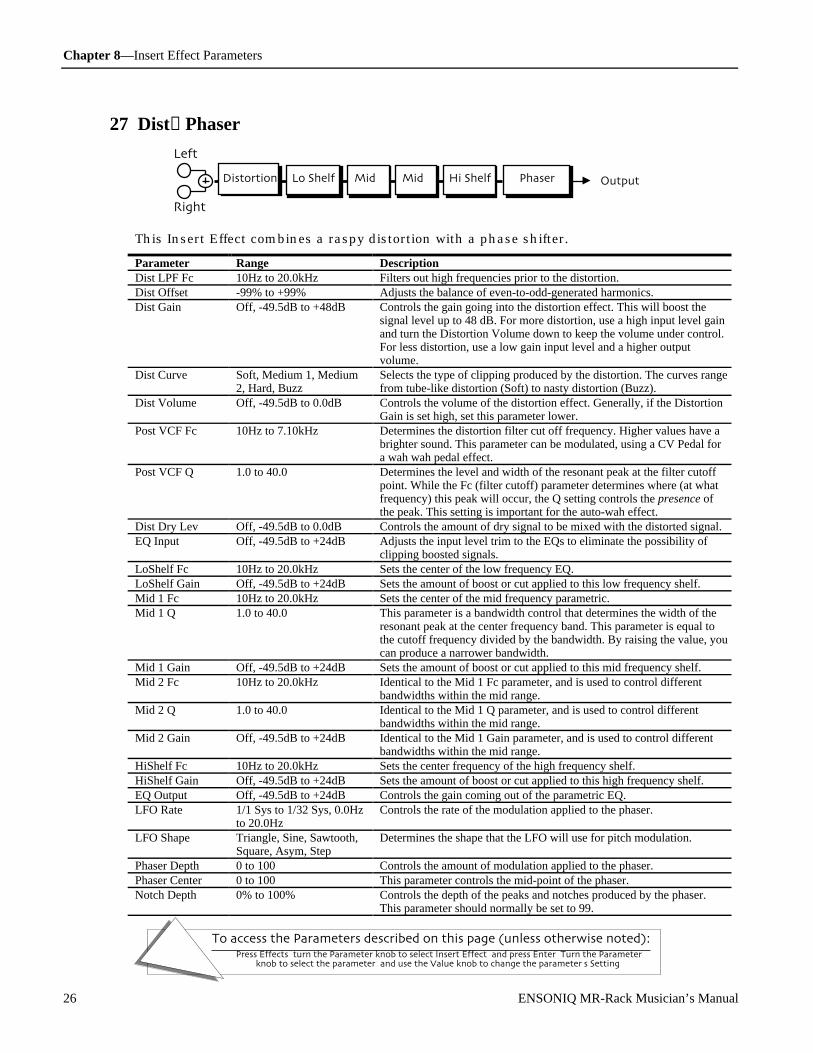
Chapter 8—Insert Effect Parameters
To access the Parameters described on this page (unless otherwise noted):Press Effects, turn the Parameter knob to select Insert Effect, and press Enter. Turn the Parameter
knob to select the parameter, and use the Value knob to change the parameter's Setting.
26 ENSONIQ MR-Rack Musician’s Manual
27 Dist→Phaser
Distortion
Right
Left
Lo Shelf Mid 1 Mid 2 Hi Shelf OutputPhaser
This Insert Effect combines a raspy distortion with a phase shifter.
Parameter Range DescriptionDist LPF Fc 10Hz to 20.0kHz Filters out high frequencies prior to the distortion.Dist Offset -99% to +99% Adjusts the balance of even-to-odd-generated harmonics.Dist Gain Off, -49.5dB to +48dB Controls the gain going into the distortion effect. This will boost the
signal level up to 48 dB. For more distortion, use a high input level gainand turn the Distortion Volume down to keep the volume under control.For less distortion, use a low gain input level and a higher outputvolume.
Dist Curve Soft, Medium 1, Medium2, Hard, Buzz
Selects the type of clipping produced by the distortion. The curves rangefrom tube-like distortion (Soft) to nasty distortion (Buzz).
Dist Volume Off, -49.5dB to 0.0dB Controls the volume of the distortion effect. Generally, if the DistortionGain is set high, set this parameter lower.
Post VCF Fc 10Hz to 7.10kHz Determines the distortion filter cut off frequency. Higher values have abrighter sound. This parameter can be modulated, using a CV Pedal fora wah wah pedal effect.
Post VCF Q 1.0 to 40.0 Determines the level and width of the resonant peak at the filter cutoffpoint. While the Fc (filter cutoff) parameter determines where (at whatfrequency) this peak will occur, the Q setting controls the presence ofthe peak. This setting is important for the auto-wah effect.
Dist Dry Lev Off, -49.5dB to 0.0dB Controls the amount of dry signal to be mixed with the distorted signal.EQ Input Off, -49.5dB to +24dB Adjusts the input level trim to the EQs to eliminate the possibility of
clipping boosted signals.LoShelf Fc 10Hz to 20.0kHz Sets the center of the low frequency EQ.LoShelf Gain Off, -49.5dB to +24dB Sets the amount of boost or cut applied to this low frequency shelf.Mid 1 Fc 10Hz to 20.0kHz Sets the center of the mid frequency parametric.Mid 1 Q 1.0 to 40.0 This parameter is a bandwidth control that determines the width of the
resonant peak at the center frequency band. This parameter is equal tothe cutoff frequency divided by the bandwidth. By raising the value, youcan produce a narrower bandwidth.
Mid 1 Gain Off, -49.5dB to +24dB Sets the amount of boost or cut applied to this mid frequency shelf.Mid 2 Fc 10Hz to 20.0kHz Identical to the Mid 1 Fc parameter, and is used to control different
bandwidths within the mid range.Mid 2 Q 1.0 to 40.0 Identical to the Mid 1 Q parameter, and is used to control different
bandwidths within the mid range.Mid 2 Gain Off, -49.5dB to +24dB Identical to the Mid 1 Gain parameter, and is used to control different
bandwidths within the mid range.HiShelf Fc 10Hz to 20.0kHz Sets the center frequency of the high frequency shelf.HiShelf Gain Off, -49.5dB to +24dB Sets the amount of boost or cut applied to this high frequency shelf.EQ Output Off, -49.5dB to +24dB Controls the gain coming out of the parametric EQ.LFO Rate 1/1 Sys to 1/32 Sys, 0.0Hz
to 20.0HzControls the rate of the modulation applied to the phaser.
LFO Shape Triangle, Sine, Sawtooth,Square, Asym, Step
Determines the shape that the LFO will use for pitch modulation.
Phaser Depth 0 to 100 Controls the amount of modulation applied to the phaser.Phaser Center 0 to 100 This parameter controls the mid-point of the phaser.Notch Depth 0% to 100% Controls the depth of the peaks and notches produced by the phaser.
This parameter should normally be set to 99.
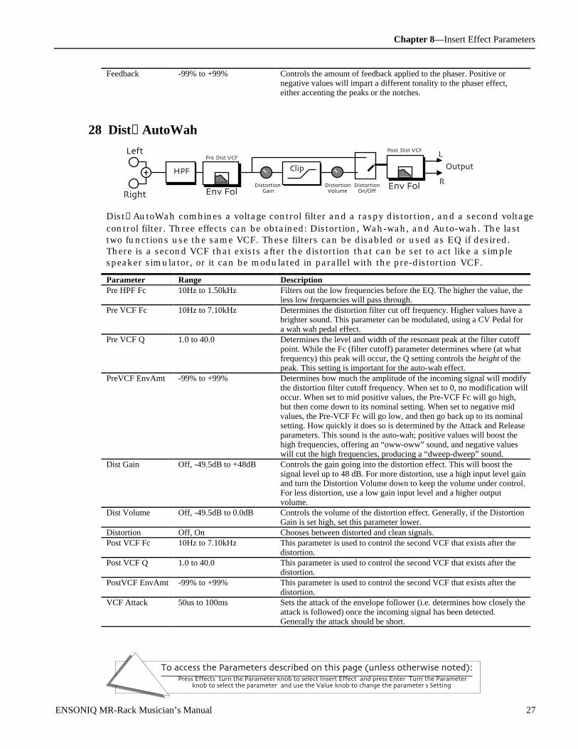
Chapter 8—Insert Effect Parameters
To access the Parameters described on this page (unless otherwise noted):Press Effects, turn the Parameter knob to select Insert Effect, and press Enter. Turn the Parameter
knob to select the parameter, and use the Value knob to change the parameter's Setting.
ENSONIQ MR-Rack Musician’s Manual 27
Feedback -99% to +99% Controls the amount of feedback applied to the phaser. Positive ornegative values will impart a different tonality to the phaser effect,either accenting the peaks or the notches.
28 Dist→AutoWah
DistortionGain
Pre-Dist VCF
DistortionVolume
Clip
Env FolDistortion
On/Off
Left
Right
R
L
Output
Post-Dist VCF
Env Fol
HPF
Dist→AutoWah combines a voltage control filter and a raspy distortion, and a second voltagecontrol filter. Three effects can be obtained: Distortion, Wah-wah, and Auto-wah. The lasttwo functions use the same VCF. These filters can be disabled or used as EQ if desired.There is a second VCF that exists after the distortion that can be set to act like a simplespeaker simulator, or it can be modulated in parallel with the pre-distortion VCF.
Parameter Range DescriptionPre HPF Fc 10Hz to 1.50kHz Filters out the low frequencies before the EQ. The higher the value, the
less low frequencies will pass through.Pre VCF Fc 10Hz to 7.10kHz Determines the distortion filter cut off frequency. Higher values have a
brighter sound. This parameter can be modulated, using a CV Pedal fora wah wah pedal effect.
Pre VCF Q 1.0 to 40.0 Determines the level and width of the resonant peak at the filter cutoffpoint. While the Fc (filter cutoff) parameter determines where (at whatfrequency) this peak will occur, the Q setting controls the height of thepeak. This setting is important for the auto-wah effect.
PreVCF EnvAmt -99% to +99% Determines how much the amplitude of the incoming signal will modifythe distortion filter cutoff frequency. When set to 0, no modification willoccur. When set to mid positive values, the Pre-VCF Fc will go high,but then come down to its nominal setting. When set to negative midvalues, the Pre-VCF Fc will go low, and then go back up to its nominalsetting. How quickly it does so is determined by the Attack and Releaseparameters. This sound is the auto-wah; positive values will boost thehigh frequencies, offering an “oww-oww” sound, and negative valueswill cut the high frequencies, producing a “dweep-dweep” sound.
Dist Gain Off, -49.5dB to +48dB Controls the gain going into the distortion effect. This will boost thesignal level up to 48 dB. For more distortion, use a high input level gainand turn the Distortion Volume down to keep the volume under control.For less distortion, use a low gain input level and a higher outputvolume.
Dist Volume Off, -49.5dB to 0.0dB Controls the volume of the distortion effect. Generally, if the DistortionGain is set high, set this parameter lower.
Distortion Off, On Chooses between distorted and clean signals.Post VCF Fc 10Hz to 7.10kHz This parameter is used to control the second VCF that exists after the
distortion.Post VCF Q 1.0 to 40.0 This parameter is used to control the second VCF that exists after the
distortion.PostVCF EnvAmt -99% to +99% This parameter is used to control the second VCF that exists after the
distortion.VCF Attack 50us to 100ms Sets the attack of the envelope follower (i.e. determines how closely the
attack is followed) once the incoming signal has been detected.Generally the attack should be short.

Chapter 8—Insert Effect Parameters
To access the Parameters described on this page (unless otherwise noted):Press Effects, turn the Parameter knob to select Insert Effect, and press Enter. Turn the Parameter
knob to select the parameter, and use the Value knob to change the parameter's Setting.
28 ENSONIQ MR-Rack Musician’s Manual
VCF Release 1ms to 10.0s Sets the amount of time after the incoming signal has ceased for theenvelope follower to shut down. Generally these times are longer thanthe attack times.
Post HPF Fc 10Hz to 1.50kHz Filters out the low frequencies after the distortion.
29 ResVCF→DDL
VCF
Right
Left
ADSREnvelope Generator
OutputL
R
2-Tap DDL
ResVCF→DDL combines a voltage control filter and a digital delay.
Parameter Range DescriptionVCF Input Off, -49.5dB to 0.0dB Acts as a trim control at the input of the VCF.VCF Fc 10Hz to 7.10kHz Determines the VCF cut off frequency. Higher values have a brighter
sound. This parameter can be modulated, using a CV Pedal for a wahwah pedal effect.
VCF Q 1.0 to 40.0 Determines the level and width of the resonant peak at the filter cutoffpoint. While the Fc (filter cutoff) parameter determines where (at whatfrequency) this peak will occur, the Q setting controls the presence of thepeak. This setting is important for the auto-wah effect.
ADSR Attack 50us to 10.0s Sets the attack time for the ADSR Envelope shape.ADSR Decay 50us to 10.0s Sets the decay time for the ADSR Envelope shape.ADSR Sustain Off, -49.5dB to 0.0dB Sets the sustain level for the ADSR Envelope shape.ADSR Release 50us to 10.0s Sets the release time for the ADSR Envelope shape.ADSR Env Amt -99% to +99% Determines the degree to which the envelope modifies the cutoff
frequency of the VCF.ADSR TrigMode Single or Multi Determines whether the envelope which controls the VCF will retrigger
with each key-event (Multi) or not (Single).Dly1 Time 1/1 Sys to 1/32 Sys, 0ms to
630msSets the amount of delay time for the first independent delay.
Dly1 Level Off, -49.5dB to +12.0dB Adjusts the volume of the delayed signal against the original dry signal.Dly1 Feedback -99% to +99% Determines the amount of signal that will be fed from the output back
into the input, increasing the number of repeats in the delay.Dly1 Damping 100Hz to 21.2kHz Controls the cutoff of a low pass filter on the feedback signal, which
adjusts the amount of damping to the feedback signals. The higher thenumber, the more the signals are damped.
Dly1 Pan Full <L to Full >R Determines the location of the delay in the stereo spectrum.Dly2 Time 1/1 Sys to 1/32 Sys, 0ms to
630msSets the amount of delay time for the second independent delay.
Dly2 Level Off, -49.5dB to +12.0dB Adjusts the volume of the delayed signal against the original dry signal.Dly2 Feedback -99% to +99% Determines the amount of signal that will be fed from the output back
into the input, increasing the number of repeats in the delay.Dly2 Damping 100Hz to 21.2kHz Controls the cutoff of a low pass filter on the feedback signal, which
adjusts the amount of damping to the feedback signals. The higher thenumber, the more the signals are damped.
Dly2 Pan Full <L to Full >R Determines the location of the delay in the stereo spectrum.
30 Dist→VCF→DDL

Chapter 8—Insert Effect Parameters
To access the Parameters described on this page (unless otherwise noted):Press Effects, turn the Parameter knob to select Insert Effect, and press Enter. Turn the Parameter
knob to select the parameter, and use the Value knob to change the parameter's Setting.
ENSONIQ MR-Rack Musician’s Manual 29
VCFDistortion
Right
Left
EQ
ADSREnvelope Generator
(Mid 1)Output
L
R
2-Tap DDL
Dist→VCF→DDL combines a distortion, a voltage control filter and a digital delay.
Parameter Range DescriptionDist LPF Fc 10Hz to 20.0kHz Filters out high frequencies prior to the distortion.Dist Offset -99% to +99% Adjusts the balance of even-to-odd-generated harmonics.Dist Gain Off, -49.5dB to +48dB Controls the gain going into the distortion effect. This will boost the
signal level up to 48 dB. For more distortion, use a high input level gainand turn the Distortion Volume down to keep the volume under control.For less distortion, use a low gain input level and a higher outputvolume.
Dist Curve Soft, Medium 1, Medium2, Hard, Buzz
Selects the type of clipping produced by the distortion. The curves rangefrom tube-like distortion (Soft) to nasty distortion (Buzz).
Dist Volume Off, -49.5dB to 0.0dB Controls the volume of the distortion effect. Generally, if the DistortionGain is set high, set this parameter lower.
Post VCF Fc 10Hz to 7.10kHz Determines the distortion filter cut off frequency. Higher values have abrighter sound. This parameter can be modulated, using a CV Pedal fora wah wah pedal effect.
Post VCF Q 1.0 to 40.0 Determines the level and width of the resonant peak at the filter cutoffpoint. While the Fc (filter cutoff) parameter determines where (at whatfrequency) this peak will occur, the Q setting controls the presence ofthe peak. This setting is important for the auto-wah effect.
Dist Dry Lev Off, -49.5dB to 0.0dB Controls the amount of dry signal to be mixed with the distorted signal.EQ Input Off, -49.5dB to +24dB Adjusts the input level trim to the EQs to eliminate the possibility of
clipping boosted signals.Mid 1 Fc 10Hz to 20.0kHz Sets the center of the mid frequency parametric.Mid 1 Q 1.0 to 40.0 This parameter is a bandwidth control that determines the width of the
resonant peak at the center frequency band. This parameter is equal tothe cutoff frequency divided by the bandwidth. By raising the value, youcan produce a narrower bandwidth.
Mid 1 Gain Off, -49.5dB to +24dB Sets the amount of boost or cut applied to this mid frequency shelf.VCF Input Off, -49.5dB to 0.0dB Acts as a trim control at the input of the VCF.VCF Fc 10Hz to 7.10kHz Determines the VCF cut off frequency. Higher values have a brighter
sound. This parameter can be modulated, using a CV Pedal for a wahwah pedal effect.
VCF Q 1.0 to 40.0 Determines the level and width of the resonant peak at the filter cutoffpoint. While the Fc (filter cutoff) parameter determines where (at whatfrequency) this peak will occur, the Q setting controls the presence ofthe peak. This setting is important for the auto-wah effect.
ADSR Attack 50us to 10.0s Sets the attack time for the ADSR Envelope shape.ADSR Decay 50us to 10.0s Sets the decay time for the ADSR Envelope shape.ADSR Sustain Off, -49.5dB to 0.0dB Sets the sustain level for the ADSR Envelope shape.ADSR Release 50us to 10.0s Sets the release time for the ADSR Envelope shape.ADSR Env Amt -99% to +99% Determines the degree to which the envelope modifies the cutoff
frequency of the VCF.ADSR TrigMode Single or Multi Determines whether the envelope which controls the VCF will retrigger
with each key-event (Multi) or not (Single).Dly1 Time 1/1 Sys to 1/32 Sys, 0ms to
630msSets the amount of delay time for the first independent delay.
Dly1 Level Off, -49.5dB to +12.0dB Adjusts the volume of the delayed signal against the original dry signal.

Chapter 8—Insert Effect Parameters
To access the Parameters described on this page (unless otherwise noted):Press Effects, turn the Parameter knob to select Insert Effect, and press Enter. Turn the Parameter
knob to select the parameter, and use the Value knob to change the parameter's Setting.
30 ENSONIQ MR-Rack Musician’s Manual
Dly1 Feedback -99% to +99% Determines the amount of signal that will be fed from the output backinto the input, increasing the number of repeats in the delay.
Dly1 Damping 100Hz to 21.2kHz Controls the cutoff of a low pass filter on the feedback signal, whichadjusts the amount of damping to the feedback signals. The higher thenumber, the more the signals are damped.
Dly1 Pan Full <L to Full >R Determines the location of the delay in the stereo spectrum.Dly2 Time 1/1 Sys to 1/32 Sys, 0ms to
630msSets the amount of delay time for the second independent delay.
Dly2 Level Off, -49.5dB to +12.0dB Adjusts the volume of the delayed signal against the original dry signal.Dly2 Feedback -99% to +99% Determines the amount of signal that will be fed from the output back
into the input, increasing the number of repeats in the delay.Dly2 Damping 100Hz to 21.2kHz Controls the cutoff of a low pass filter on the feedback signal, which
adjusts the amount of damping to the feedback signals. The higher thenumber, the more the signals are damped.
Dly2 Pan Full <L to Full >R Determines the location of the delay in the stereo spectrum.
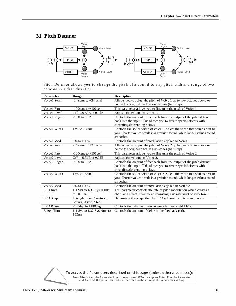
Chapter 8—Insert Effect Parameters
To access the Parameters described on this page (unless otherwise noted):Press Effects, turn the Parameter knob to select Insert Effect, and press Enter. Turn the Parameter
knob to select the parameter, and use the Value knob to change the parameter's Setting.
ENSONIQ MR-Rack Musician’s Manual 31
31 Pitch Detuner
Right
Voice 1
DDL
Voice 2Voice2Regen
Voice1 Level
Voice2 Level
Voice 1Regen
Left
OutLeft
Voice 1
DDL
Voice 2Voice2Regen
Voice1 Level
Voice2 Level
Voice 1Regen
Right
Out
Pitch Detuner allows you to change the pitch of a sound to any pitch within a range of twooctaves in either direction.
Parameter Range DescriptionVoice1 Semi -24 semi to +24 semi Allows you to adjust the pitch of Voice 1 up to two octaves above or
below the original pitch in semi-tones (half steps).Voice1 Fine -100cent to +100cent This parameter allows you to fine tune the pitch of Voice 1.Voice1 Level Off, -49.5dB to 0.0dB Adjusts the volume of Voice 1.Voice1 Regen -99% to +99% Controls the amount of feedback from the output of the pitch detuner
back into the input. This allows you to create special effects withascending/descending delays.
Voice1 Width 1ms to 185ms Controls the splice width of voice 1. Select the width that sounds best toyou. Shorter values result in a grainier sound, while longer values soundsmoother.
Voice1 Mod 0% to 100% Controls the amount of modulation applied to Voice 1.Voice2 Semi -24 semi to +24 semi Allows you to adjust the pitch of Voice 2 up to two octaves above or
below the original pitch in semi-tones (half steps).Voice2 Fine -100cent to +100cent This parameter allows you to fine tune the pitch of Voice 2.Voice2 Level Off, -49.5dB to 0.0dB Adjusts the volume of Voice 2.Voice2 Regen -99% to +99% Controls the amount of feedback from the output of the pitch detuner
back into the input. This allows you to create special effects withascending/descending delays.
Voice2 Width 1ms to 185ms Controls the splice width of voice 2. Select the width that sounds best toyou. Shorter values result in a grainier sound, while longer values soundsmoother.
Voice2 Mod 0% to 100% Controls the amount of modulation applied to Voice 2.LFO Rate 1/1 Sys to 1/32 Sys, 0.0Hz
to 20.0HzThis parameter controls the rate of pitch modulation which creates achorusing effect. To achieve chorusing, this rate must be very low.
LFO Shape Triangle, Sine, Sawtooth,Square, Asym, Step
Determines the shape that the LFO will use for pitch modulation.
LFO Phase -180deg to +180deg Controls the relative phase between left and right LFOs.Regen Time 1/1 Sys to 1/32 Sys, 0ms to
185msControls the amount of delay in the feedback path.
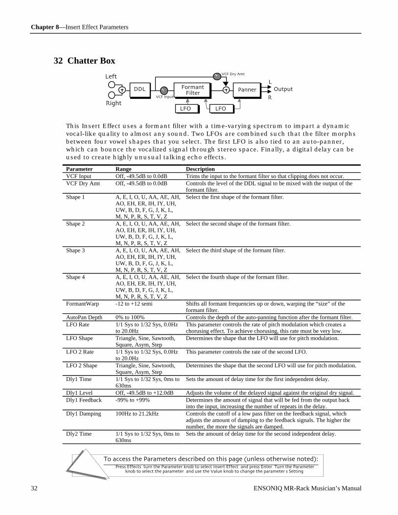
Chapter 8—Insert Effect Parameters
To access the Parameters described on this page (unless otherwise noted):Press Effects, turn the Parameter knob to select Insert Effect, and press Enter. Turn the Parameter
knob to select the parameter, and use the Value knob to change the parameter's Setting.
32 ENSONIQ MR-Rack Musician’s Manual
32 Chatter Box
OutputFormantFilter
Right
Left
DDLL
R
Panner
VCF Dry Amt
VCF Input
LFO 2 LFO 1
This Insert Effect uses a formant filter with a time-varying spectrum to impart a dynamicvocal-like quality to almost any sound. Two LFOs are combined such that the filter morphsbetween four vowel shapes that you select. The first LFO is also tied to an auto-panner,which can bounce the vocalized signal through stereo space. Finally, a digital delay can beused to create highly unusual talking echo effects.
Parameter Range DescriptionVCF Input Off, -49.5dB to 0.0dB Trims the input to the formant filter so that clipping does not occur.VCF Dry Amt Off, -49.5dB to 0.0dB Controls the level of the DDL signal to be mixed with the output of the
formant filter.Shape 1 A, E, I, O, U, AA, AE, AH,
AO, EH, ER, IH, IY, UH,UW, B, D, F, G, J, K, L,M, N, P, R, S, T, V, Z
Select the first shape of the formant filter.
Shape 2 A, E, I, O, U, AA, AE, AH,AO, EH, ER, IH, IY, UH,UW, B, D, F, G, J, K, L,M, N, P, R, S, T, V, Z
Select the second shape of the formant filter.
Shape 3 A, E, I, O, U, AA, AE, AH,AO, EH, ER, IH, IY, UH,UW, B, D, F, G, J, K, L,M, N, P, R, S, T, V, Z
Select the third shape of the formant filter.
Shape 4 A, E, I, O, U, AA, AE, AH,AO, EH, ER, IH, IY, UH,UW, B, D, F, G, J, K, L,M, N, P, R, S, T, V, Z
Select the fourth shape of the formant filter.
FormantWarp -12 to +12 semi Shifts all formant frequencies up or down, warping the “size” of theformant filter.
AutoPan Depth 0% to 100% Controls the depth of the auto-panning function after the formant filter.LFO Rate 1/1 Sys to 1/32 Sys, 0.0Hz
to 20.0HzThis parameter controls the rate of pitch modulation which creates achorusing effect. To achieve chorusing, this rate must be very low.
LFO Shape Triangle, Sine, Sawtooth,Square, Asym, Step
Determines the shape that the LFO will use for pitch modulation.
LFO 2 Rate 1/1 Sys to 1/32 Sys, 0.0Hzto 20.0Hz
This parameter controls the rate of the second LFO.
LFO 2 Shape Triangle, Sine, Sawtooth,Square, Asym, Step
Determines the shape that the second LFO will use for pitch modulation.
Dly1 Time 1/1 Sys to 1/32 Sys, 0ms to630ms
Sets the amount of delay time for the first independent delay.
Dly1 Level Off, -49.5dB to +12.0dB Adjusts the volume of the delayed signal against the original dry signal.Dly1 Feedback -99% to +99% Determines the amount of signal that will be fed from the output back
into the input, increasing the number of repeats in the delay.Dly1 Damping 100Hz to 21.2kHz Controls the cutoff of a low pass filter on the feedback signal, which
adjusts the amount of damping to the feedback signals. The higher thenumber, the more the signals are damped.
Dly2 Time 1/1 Sys to 1/32 Sys, 0ms to630ms
Sets the amount of delay time for the second independent delay.

Chapter 8—Insert Effect Parameters
To access the Parameters described on this page (unless otherwise noted):Press Effects, turn the Parameter knob to select Insert Effect, and press Enter. Turn the Parameter
knob to select the parameter, and use the Value knob to change the parameter's Setting.
ENSONIQ MR-Rack Musician’s Manual 33
Dly2 Level Off, -49.5dB to +12.0dB Adjusts the volume of the delayed signal against the original dry signal.Dly2 Feedback -99% to +99% Determines the amount of signal that will be fed from the output back
into the input, increasing the number of repeats in the delay.Dly2 Damping 100Hz to 21.2kHz Controls the cutoff of a low pass filter on the feedback signal, which
adjusts the amount of damping to the feedback signals. The higher thenumber, the more the signals are damped.
33 Formant Morph
OutputFormantFilter
Right
Left
DDLL
R
Panner
VCF Dry Amt
VCF Input
LFO
Dist
This effect is similar to the Chatter Box, except that it has a distorter for increased harmoniccontent, and it uses a single LFO to morph between two vowel shapes that you select.
Parameter Range DescriptionDist Gain Off, -49.5dB to +48dB Controls the gain going into the distortion effect. This will boost the
signal level up to 48 dB. For more distortion, use a high input level gainand turn the Distortion Volume down to keep the volume under control.For less distortion, use a low gain input level and a higher outputvolume.
Dist Volume Off, -49.5dB to 0.0dB Controls the volume of the distortion effect. Generally, if the DistortionGain is set high, set this parameter lower.
Dist LPF Fc 10Hz to 20.0kHz Filters out high frequencies prior to the distortion.Post VCF Fc 10Hz to 7.10kHz Determines the distortion filter cut off frequency. Higher values have a
brighter sound. This parameter can be modulated, using a CV Pedal fora wah wah pedal effect.
Post VCF Q 1.0 to 40.0 Determines the level and width of the resonant peak at the filter cutoffpoint. While the Fc (filter cutoff) parameter determines where (at whatfrequency) this peak will occur, the Q setting controls the presence ofthe peak. This setting is important for the auto-wah effect.
Dist Offset -99% to +99% Adjusts the balance of even-to-odd-generated harmonics.Dist Curve Soft, Medium 1, Medium
2, Hard, BuzzSelects the type of clipping produced by the distortion. The curves rangefrom tube-like distortion (Soft) to nasty distortion (Buzz).
Dist Dry Lev Off, -49.5dB to 0.0dB Controls the amount of dry signal to be mixed with the distorted signal.VCF Input Off, -49.5dB to 0.0dB Trims the input to the formant filter so that clipping does not occur.VCF Dry Amt Off, -49.5dB to +24dB Controls the level of the distortion/DDL signal to be mixed with the
output of the formant filter.Shape 1 A, E, I, O, U, AA, AE, AH,
AO, EH, ER, IH, IY, UH,UW, B, D, F, G, J, K, L,M, N, P, R, S, T, V, Z
Selects the first shape of the formant filter.
Shape 2 A, E, I, O, U, AA, AE, AH,AO, EH, ER, IH, IY, UH,UW, B, D, F, G, J, K, L,M, N, P, R, S, T, V, Z
Selects the second shape of the formant filter.
FormantWarp -12 to +12 semi Shifts all formant frequencies up or down, warping the “size” of theformant filter.
AutoPan Depth 0% to 100% Controls the depth of the auto-panning function after the formant filter.LFO Rate 1/1 Sys to 1/32 Sys, 0.0Hz
to 20.0HzThis parameter controls the rate of pitch modulation which creates achorusing effect. To achieve chorusing, this rate must be very low.

Chapter 8—Insert Effect Parameters
To access the Parameters described on this page (unless otherwise noted):Press Effects, turn the Parameter knob to select Insert Effect, and press Enter. Turn the Parameter
knob to select the parameter, and use the Value knob to change the parameter's Setting.
34 ENSONIQ MR-Rack Musician’s Manual
LFO Shape Triangle, Sine, Sawtooth,Square, Asym, Step
Determines the shape that the LFO will use for pitch modulation.
LFO Phase -180deg to +180deg Controls the relative phase between left and right LFOs.Dly1 Time 1/1 Sys to 1/32 Sys, 0ms to
630msSets the amount of delay time for the first independent delay.
Dly1 Level Off, -49.5dB to +12.0dB Adjusts the volume of the delayed signal against the original dry signal.Dly1 Feedback -99% to +99% Determines the amount of signal that will be fed from the output back
into the input, increasing the number of repeats in the delay.Dly1 Damping 100Hz to 21.2kHz Controls the cutoff of a low pass filter on the feedback signal, which
adjusts the amount of damping to the feedback signals. The higher thenumber, the more the signals are damped.
Dly2 Time 1/1 Sys to 1/32 Sys, 0ms to630ms
Sets the amount of delay time for the second independent delay.
Dly2 Level Off, -49.5dB to +12.0dB Adjusts the volume of the delayed signal against the original dry signal.Dly2 Feedback -99% to +99% Determines the amount of signal that will be fed from the output back
into the input, increasing the number of repeats in the delay.Dly2 Damping 100Hz to 21.2kHz Controls the cutoff of a low pass filter on the feedback signal, which
adjusts the amount of damping to the feedback signals. The higher thenumber, the more the signals are damped.
34 RotarySpeaker
OutputCrossoverDistortion
Right
Left
EQL
RRotor Mix
High Rotor
Low Rotor
Rotor Mix
Lo Hi Bal
(Mid 1)
This Insert Effect adds the famous classic rotating speaker effect to any sound. A tunabledistortion is added to the input signal and is also passed through the rotors.
Parameter Range DescriptionDist LPF Fc 10Hz to 20.0kHz Filters out high frequencies prior to the distortion.Dist Offset -99% to +99% Adjusts the balance of even-to-odd-generated harmonics.Dist Gain Off, -49.5dB to +48dB Controls the gain going into the distortion effect. This will boost the
signal level up to 48 dB. For more distortion, use a high input level gainand turn the Distortion Volume down to keep the volume under control.For less distortion, use a low gain input level and a higher output volume.
Dist Curve Soft, Medium 1, Medium2, Hard, Buzz
Selects the type of clipping produced by the distortion. The curves rangefrom tube-like distortion (Soft) to nasty distortion (Buzz).
Dist Volume Off, -49.5dB to 0.0dB Controls the volume of the distortion effect. Generally, if the DistortionGain is set high, set this parameter lower.
Post VCF Fc 10Hz to 7.10kHz Determines the distortion filter cut off frequency. Higher values have abrighter sound. This parameter can be modulated, using a CV Pedal for awah wah pedal effect.
Post VCF Q 1.0 to 40.0 Determines the level and width of the resonant peak at the filter cutoffpoint. While the Fc (filter cutoff) parameter determines where (at whatfrequency) this peak will occur, the Q setting controls the presence of thepeak. This setting is important for the auto-wah effect.
Dist Dry Lev Off, -49.5dB to 0.0dB Controls the amount of dry signal to be mixed with the distorted signal.EQ Input Off, -49.5dB to +24dB Adjusts the input level trim to the EQs to eliminate the possibility of
clipping boosted signals.Mid 1 Fc 10Hz to 20.0kHz Sets the center of the mid frequency parametric.

Chapter 8—Insert Effect Parameters
To access the Parameters described on this page (unless otherwise noted):Press Effects, turn the Parameter knob to select Insert Effect, and press Enter. Turn the Parameter
knob to select the parameter, and use the Value knob to change the parameter's Setting.
ENSONIQ MR-Rack Musician’s Manual 35
Mid 1 Q 1.0 to 40.0 This parameter is a bandwidth control that determines the width of theresonant peak at the center frequency band. This parameter is equal to thecutoff frequency divided by the bandwidth. By raising the value, you canproduce a narrower bandwidth.
Mid 1 Gain Off, -49.5dB to +24dB Sets the amount of boost or cut applied to this mid frequency parametric.Speed Slow or Fast Determines how the rotating speaker will switch between slow and fast
speeds. The behavior of this switch accurately reflects an actual rotaryspeaker, taking time to speed up or slow down, based on the values of theInertia parameters. By assigning a modulation controller to thisparameter, you can change between the slow and fast speeds in real time.
Spread Stereo or Mono Selects either a stereo or mono rotary speaker effect.Crossover Fc 10Hz to 20.0kHz Sets the crossover frequency between the low and high rotors.Lo Hi Bal Full <Lo to Full >Hi Controls the balance between the low and the high rotor.Rotor Mix Full Dry to Full Wet Controls the balance between the leakage (dry) signal and the rotor (wet)
signal. We recommend settings near 70.0% wet.Hi Inertia 100ms to 10.0s Determines how long it will take for the rotor effect to speed up to the
high setting after switching from slow. Adjust this parameter to simulatethe effect of the rotary speaker gradually picking up speed.
Hi Slow 0.0Hz to 10.0Hz Sets the rotary speaker’s “slow” rate when the Lo Hi Bal parameter is setto “Hi,” or when the selected modulator is at zero output level. Thehigher the value, the faster the rate.
Hi Fast 0.0Hz to 10.0Hz Sets the rotary speaker’s “fast” rate when the Lo Hi Bal parameter is setto “Hi,” or when the selected modulator is at zero output level. Thehigher the value, the faster the rate.
Hi FM Min 0 to 100 Sets the minimum amount of detuning as the speaker rotates when the LoHi Bal parameter is set to “Hi.”
Hi FM Max 0 to 100 Sets the maximum amount of detuning as the speaker rotates when the LoHi Bal parameter is set to “Hi.” These two parameters create what is alsoknown as the “Doppler” effect.
Hi AM Min 0 to 100 Sets the minimum amount that the volume will change as the speakerrotates when the Lo Hi Bal parameter is set to “Hi.”
Hi AM Max 0 to 100 Sets the maximum amount that the volume will change as the speakerrotates when the Lo Hi Bal parameter is set to “Hi.” Broader rangesbetween these two parameters will create a deeper rotating speaker effect.
Lo Inertia 100ms to 10.0s Determines how long it will take for the rotor effect to slow down to thelow setting after switching from Fast. Adjust this parameter to simulatethe effect of the rotary speaker gradually slowing down.
Lo Slow 0.0Hz to 10.0Hz Sets the rotary speaker’s “slow” rate when the Lo Hi Bal parameter is setto “Lo,” or when the selected modulator is at zero output level. Thehigher the value, the faster the rate.
Lo Fast 0.0Hz to 10.0Hz Sets the rotary speaker’s “fast” rate when the Lo Hi Bal parameter is setto “Lo,” or when the selected modulator is at zero output level. Thehigher the value, the faster the rate.
Lo FM Min 0 to 100 Sets the minimum amount of detuning as the speaker rotates when the LoHi Bal parameter is set to “Lo.”
Lo FM Max 0 to 100 Sets the maximum amount of detuning as the speaker rotates when the LoHi Bal parameter is set to “Lo.” These two parameters create what is alsoknown as the “Doppler” effect.
Lo AM Min 0 to 100 Sets the minimum amount that the volume will change as the speakerrotates when the Lo Hi Bal parameter is set to “Lo.”
Lo AM Max 0 to 100 Sets the maximum amount that the volume will change as the speakerrotates when the Lo Hi Bal parameter is set to “Lo.” Broader rangesbetween these two parameters will create a deeper rotating speaker effect.

Chapter 8—Insert Effect Parameters
To access the Parameters described on this page (unless otherwise noted):Press Effects, turn the Parameter knob to select Insert Effect, and press Enter. Turn the Parameter
knob to select the parameter, and use the Value knob to change the parameter's Setting.
36 ENSONIQ MR-Rack Musician’s Manual
Speed Control Normal or Toggle Allows you to select a modulator and define what type of modulation youwant to use to affect the rotor speed. The two modulation modes are:• Normal — The modulation source continuously switches between theSpeed slow setting and fast setting, based on the mod source positionand/or movement. Try this setting with a Mod Wheel — you’ll hear therotary speaker change speed based on the position of the wheel (and thespeed settings).• Toggle — The modulation source toggles the rotor speed between theSpeed slow setting and fast setting. Every time the modulation sourcemoves from zero in a positive direction, the rotating speaker effectchanges speeds from slow to fast or fast to slow. Try this setting with aSustain pedal.With both types of modulation, the rotary speaker always takes theInertia time to get to the Rotor Speed Slow and Fast settings.
35 Tunable Spkr
OutputInput HPF
Right
Left
Mid 1L
REQ Input
Mid 2 Mid 3 HPF LPFEQ Output
This Insert Effect offers an EQ controllable speaker sound. By tuning three parametricfilters, you can simulate many different speaker cabinet sounds that are used in all styles ofmusic.
Parameter Range DescriptionPre HP Fc 10Hz to 1.50kHz Controls the boost or cut of the high pass filter frequency applied to the
input signal.EQ Input Off, -49.5dB to +24dB This parameter allows you to adjust the input level before the EQs to
eliminate the possibility of clipping boosted signals.Mid 1 Fc 10Hz to 20.0kHz Sets the center of the mid-frequency parametric. Higher values have a
brighter sound.Mid 1 Q 1.0 to 40.0 This parameter is a bandwidth control that determines the width of the
resonant peak at the center frequency band. This parameter is equal to thecutoff frequency divided by the bandwidth. By raising the value, you canproduce a narrower bandwidth.
Mid 1 Gain Off, -49.5dB to +24dB Sets the amount of boost or cut applied to this mid frequency shelf.Mid 2 Fc 10Hz to 20.0kHz Identical to the Mid 1 Fc parameter, and is used to control different
bandwidths within the mid range.Mid 2 Q 1.0 to 40.0 Identical to the Mid 1 Q parameter, and is used to control different
bandwidths within the mid range.Mid 2 Gain Off, -49.5dB to +24dB Identical to the Mid 1 Gain parameter, and is used to control different
bandwidths within the mid range.Mid 3 Fc 10Hz to 20.0kHz Identical to the Mid 1 Fc parameter, and is used to control different
bandwidths within the mid range.Mid 3 Q 1.0 to 40.0 Identical to the Mid 1 Q parameter, and is used to control different
bandwidths within the mid range.Mid 3 Gain Off, -49.5dB to +24dB Identical to the Mid 1 Gain parameter, and is used to control different
bandwidths within the mid range.EQ Output Off, -49.5dB to +24dB Since speaker cabinets are “lossy,” output gain is required to compensate
losses in perceived volume. Setting this gain too high will cause clippingof the output signal.
HPF Cutoff 10Hz to 20.0kHz Filters out the low frequencies. The higher the value, the less lowfrequencies pass through. This parameter is used to increase brightness.
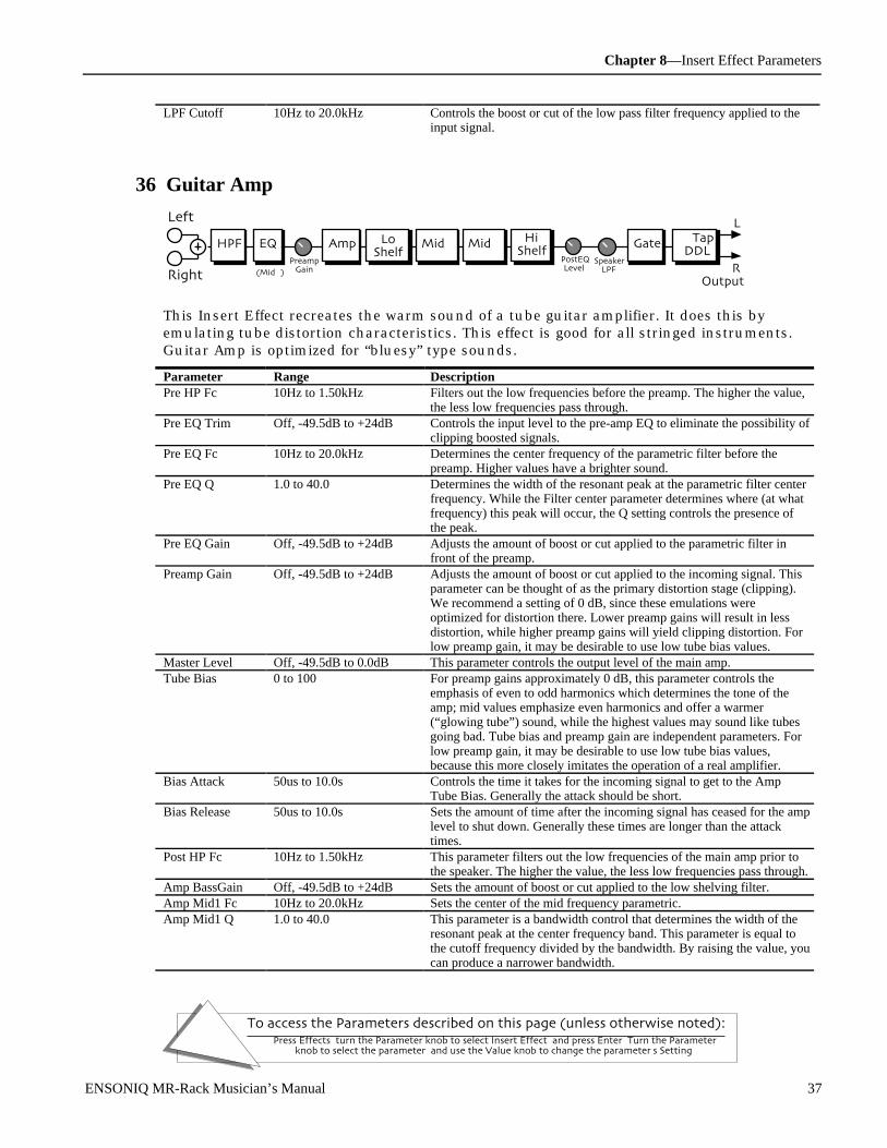
Chapter 8—Insert Effect Parameters
To access the Parameters described on this page (unless otherwise noted):Press Effects, turn the Parameter knob to select Insert Effect, and press Enter. Turn the Parameter
knob to select the parameter, and use the Value knob to change the parameter's Setting.
ENSONIQ MR-Rack Musician’s Manual 37
LPF Cutoff 10Hz to 20.0kHz Controls the boost or cut of the low pass filter frequency applied to theinput signal.
36 Guitar Amp
Output
L
RRight
Left
EQ
(Mid 1)
PreampGain
HPFPostEQLevel
2-TapDDL
GateAmp LoShelf
Mid 1 Mid 2 HiShelf
SpeakerLPF
This Insert Effect recreates the warm sound of a tube guitar amplifier. It does this byemulating tube distortion characteristics. This effect is good for all stringed instruments.Guitar Amp is optimized for “bluesy” type sounds.
Parameter Range DescriptionPre HP Fc 10Hz to 1.50kHz Filters out the low frequencies before the preamp. The higher the value,
the less low frequencies pass through.Pre EQ Trim Off, -49.5dB to +24dB Controls the input level to the pre-amp EQ to eliminate the possibility of
clipping boosted signals.Pre EQ Fc 10Hz to 20.0kHz Determines the center frequency of the parametric filter before the
preamp. Higher values have a brighter sound.Pre EQ Q 1.0 to 40.0 Determines the width of the resonant peak at the parametric filter center
frequency. While the Filter center parameter determines where (at whatfrequency) this peak will occur, the Q setting controls the presence ofthe peak.
Pre EQ Gain Off, -49.5dB to +24dB Adjusts the amount of boost or cut applied to the parametric filter infront of the preamp.
Preamp Gain Off, -49.5dB to +24dB Adjusts the amount of boost or cut applied to the incoming signal. Thisparameter can be thought of as the primary distortion stage (clipping).We recommend a setting of 0 dB, since these emulations wereoptimized for distortion there. Lower preamp gains will result in lessdistortion, while higher preamp gains will yield clipping distortion. Forlow preamp gain, it may be desirable to use low tube bias values.
Master Level Off, -49.5dB to 0.0dB This parameter controls the output level of the main amp.Tube Bias 0 to 100 For preamp gains approximately 0 dB, this parameter controls the
emphasis of even to odd harmonics which determines the tone of theamp; mid values emphasize even harmonics and offer a warmer(“glowing tube”) sound, while the highest values may sound like tubesgoing bad. Tube bias and preamp gain are independent parameters. Forlow preamp gain, it may be desirable to use low tube bias values,because this more closely imitates the operation of a real amplifier.
Bias Attack 50us to 10.0s Controls the time it takes for the incoming signal to get to the AmpTube Bias. Generally the attack should be short.
Bias Release 50us to 10.0s Sets the amount of time after the incoming signal has ceased for the amplevel to shut down. Generally these times are longer than the attacktimes.
Post HP Fc 10Hz to 1.50kHz This parameter filters out the low frequencies of the main amp prior tothe speaker. The higher the value, the less low frequencies pass through.
Amp BassGain Off, -49.5dB to +24dB Sets the amount of boost or cut applied to the low shelving filter.Amp Mid1 Fc 10Hz to 20.0kHz Sets the center of the mid frequency parametric.Amp Mid1 Q 1.0 to 40.0 This parameter is a bandwidth control that determines the width of the
resonant peak at the center frequency band. This parameter is equal tothe cutoff frequency divided by the bandwidth. By raising the value, youcan produce a narrower bandwidth.
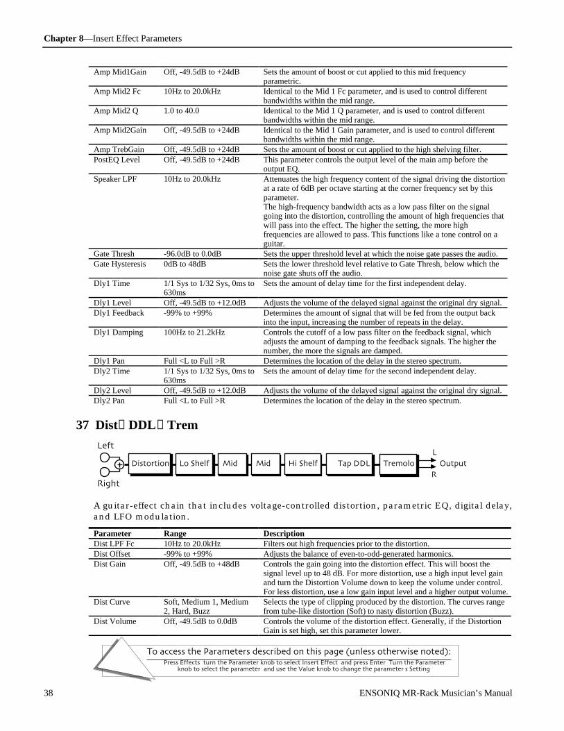
Chapter 8—Insert Effect Parameters
To access the Parameters described on this page (unless otherwise noted):Press Effects, turn the Parameter knob to select Insert Effect, and press Enter. Turn the Parameter
knob to select the parameter, and use the Value knob to change the parameter's Setting.
38 ENSONIQ MR-Rack Musician’s Manual
Amp Mid1Gain Off, -49.5dB to +24dB Sets the amount of boost or cut applied to this mid frequencyparametric.
Amp Mid2 Fc 10Hz to 20.0kHz Identical to the Mid 1 Fc parameter, and is used to control differentbandwidths within the mid range.
Amp Mid2 Q 1.0 to 40.0 Identical to the Mid 1 Q parameter, and is used to control differentbandwidths within the mid range.
Amp Mid2Gain Off, -49.5dB to +24dB Identical to the Mid 1 Gain parameter, and is used to control differentbandwidths within the mid range.
Amp TrebGain Off, -49.5dB to +24dB Sets the amount of boost or cut applied to the high shelving filter.PostEQ Level Off, -49.5dB to +24dB This parameter controls the output level of the main amp before the
output EQ.Speaker LPF 10Hz to 20.0kHz Attenuates the high frequency content of the signal driving the distortion
at a rate of 6dB per octave starting at the corner frequency set by thisparameter.The high-frequency bandwidth acts as a low pass filter on the signalgoing into the distortion, controlling the amount of high frequencies thatwill pass into the effect. The higher the setting, the more highfrequencies are allowed to pass. This functions like a tone control on aguitar.
Gate Thresh -96.0dB to 0.0dB Sets the upper threshold level at which the noise gate passes the audio.Gate Hysteresis 0dB to 48dB Sets the lower threshold level relative to Gate Thresh, below which the
noise gate shuts off the audio.Dly1 Time 1/1 Sys to 1/32 Sys, 0ms to
630msSets the amount of delay time for the first independent delay.
Dly1 Level Off, -49.5dB to +12.0dB Adjusts the volume of the delayed signal against the original dry signal.Dly1 Feedback -99% to +99% Determines the amount of signal that will be fed from the output back
into the input, increasing the number of repeats in the delay.Dly1 Damping 100Hz to 21.2kHz Controls the cutoff of a low pass filter on the feedback signal, which
adjusts the amount of damping to the feedback signals. The higher thenumber, the more the signals are damped.
Dly1 Pan Full <L to Full >R Determines the location of the delay in the stereo spectrum.Dly2 Time 1/1 Sys to 1/32 Sys, 0ms to
630msSets the amount of delay time for the second independent delay.
Dly2 Level Off, -49.5dB to +12.0dB Adjusts the volume of the delayed signal against the original dry signal.Dly2 Pan Full <L to Full >R Determines the location of the delay in the stereo spectrum.
37 Dist→DDL→Trem
Distortion
Right
Left
Lo Shelf Mid 1 Mid 2 Hi Shelf Output
L
R
2-Tap DDL Tremolo
A guitar-effect chain that includes voltage-controlled distortion, parametric EQ, digital delay,and LFO modulation.
Parameter Range DescriptionDist LPF Fc 10Hz to 20.0kHz Filters out high frequencies prior to the distortion.Dist Offset -99% to +99% Adjusts the balance of even-to-odd-generated harmonics.Dist Gain Off, -49.5dB to +48dB Controls the gain going into the distortion effect. This will boost the
signal level up to 48 dB. For more distortion, use a high input level gainand turn the Distortion Volume down to keep the volume under control.For less distortion, use a low gain input level and a higher output volume.
Dist Curve Soft, Medium 1, Medium2, Hard, Buzz
Selects the type of clipping produced by the distortion. The curves rangefrom tube-like distortion (Soft) to nasty distortion (Buzz).
Dist Volume Off, -49.5dB to 0.0dB Controls the volume of the distortion effect. Generally, if the DistortionGain is set high, set this parameter lower.

Chapter 8—Insert Effect Parameters
To access the Parameters described on this page (unless otherwise noted):Press Effects, turn the Parameter knob to select Insert Effect, and press Enter. Turn the Parameter
knob to select the parameter, and use the Value knob to change the parameter's Setting.
ENSONIQ MR-Rack Musician’s Manual 39
Post VCF Fc 10Hz to 7.10kHz Determines the filter cut off-frequency after the distortion. Higher valueshave a brighter sound. This parameter can be used to emulate a speakercabinet.
Post VCF Q 1.0 to 40.0 Determines the level and width of the resonant peak at the filter cutoffpoint. While the Post VCF Fc parameter determines where (at what-frequency) this peak will occur, this parameter controls the sharpness ofthe peak.
Dist Dry Lev Off, -49.5dB to 0.0dB Controls the amount of dry signal to be mixed with the distorted signal.LoShelf Gain Off, -49.5dB to +24dB Sets the amount of boost or cut applied to the low frequency shelf.HiShelf Gain Off, -49.5dB to +24dB Sets the amount of boost or cut applied to the high frequency shelf.Mid 1 Fc 10Hz to 20.0kHz Sets the center of the mid frequency parametric.Mid 1 Q 1.0 to 40.0 This parameter is a bandwidth control that determines the width of the
resonant peak at the center frequency band. This parameter is equal to thecutoff frequency divided by the bandwidth. By raising the value, you canproduce a narrower bandwidth.
Mid 1 Gain Off, -49.5dB to +24dB Sets the amount of boost or cut applied to this mid frequency shelf.Mid 2 Fc 10Hz to 20.0kHz Identical to the Mid 1 Fc parameter, and is used to control different
bandwidths within the mid range.Mid 2 Q 1.0 to 40.0 Identical to the Mid 1 Q parameter, and is used to control different
bandwidths within the mid range.Mid 2 Gain Off, -49.5dB to +24dB Identical to the Mid 1 Gain parameter, and is used to control different
bandwidths within the mid range.EQ Output Off, -49.5dB to +24dB Controls the gain coming out of the parametric EQ.Dly1 Time 1/1 Sys to 1/32 Sys, 0ms to
630msSets the amount of delay time for the first independent delay.
Dly1 Level Off, -49.5dB to +12.0dB Adjusts the volume of the delayed signal against the original dry signal.Dly1 Feedback -99% to +99% Determines the amount of signal that will be fed from the output back
into the input, increasing the number of repeats in the delay.Dly1 Damping 100Hz to 21.2kHz Controls the cutoff of a low pass filter on the feedback signal, which
adjusts the amount of damping to the feedback signals. The higher thenumber, the more the signals are damped.
Dly1 Pan Full <L to Full >R Determines the location of the delay in the stereo spectrum.Dly2 Time 1/1 Sys to 1/32 Sys, 0ms to
630msSets the amount of delay time for the second independent delay.
Dly2 Level Off, -49.5dB to +12.0dB Adjusts the volume of the delayed signal against the original dry signal.Dly2 Feedback -99% to +99% Determines the amount of signal that will be fed from the output back
into the input, increasing the number of repeats in the delay.Dly2 Damping 100Hz to 21.2kHz Controls the cutoff of a low pass filter on the feedback signal, which
adjusts the amount of damping to the feedback signals. The higher thenumber, the more the signals are damped.
Dly2 Pan Full <L to Full >R Determines the location of the delay in the stereo spectrum.LFO Rate 1/1 Sys to 1/32 Sys, 0.0Hz
to 20.0HzControls the rate of the modulation applied to the tremolo.
LFO Shape Triangle, Sine, Sawtooth,Square, Asym, Step
Determines the shape that the LFO will use for amplitude modulation.
LFO Phase -180deg to +180deg Controls the relative phase between left and right LFOs.LFO Depth Full Dry to Full Wet Controls the amount of tremolo.
38 Comp→Dist→DDL
Dist
Right
Left
Comp Gate Lo Shelf Mid 1 Mid 2 Hi Shelf OutputL
R
2-Tap DDL

Chapter 8—Insert Effect Parameters
To access the Parameters described on this page (unless otherwise noted):Press Effects, turn the Parameter knob to select Insert Effect, and press Enter. Turn the Parameter
knob to select the parameter, and use the Value knob to change the parameter's Setting.
40 ENSONIQ MR-Rack Musician’s Manual
A bright guitar-effects chain that features compression, voltage-controlled distortion,parametric EQ, and a digital delay.
Parameter Range DescriptionComp Ratio 1.0:1 to INF:1 Sets the amount of compression. The range is based on decibels (dB)
above the threshold. If set to 4:1 for example, it will allow 1 dB increasein output level for every 4 dB increase in input level. When set toinfinity, it acts as a limiter.
Comp Attack 50us to 10.0s Determines the attack rate after the initial signal has been detected andbefore the compression takes affect.
Comp Release 50us to 10.0s Determines how long it takes for the compression to be fully deactivatedafter the input signal drops below the threshold level. This is generallychosen longer than the attack time.
Comp Thresh -96.0dB to 0.0dB Sets the threshold level. Signals that exceed this level will becompressed, while signals that are below will be unaffected. To turn offthe compressor, set the level to +00 dB.
Comp Output Off, -49.5dB to +48dB This parameter boosts or cuts the compressed signal level.Gate Thresh -96.0dB to 0.0dB Sets the upper threshold level at which the noise gate passes the audio.Gate Hysteresis 0dB to 48dB Sets the lower threshold level relative to Gate Thresh, below which the
noise gate shuts off the audio.Dist LPF Fc 10Hz to 20.0kHz Filters out high frequencies prior to the distortion.Dist Offset -99% to +99% Adjusts the balance of even-to-odd-generated harmonics.Dist Gain Off, -49.5dB to +48dB Controls the gain going into the distortion effect. This will boost the
signal level up to 48 dB. For more distortion, use a high input level gainand turn the Distortion Gain Out down to keep the volume under control.For less distortion, use a low gain input level and a higher output volume.
Dist Curve Soft, Medium 1, Medium2, Hard, Buzz
Selects the type of clipping produced by the distortion. The curves rangefrom tube-like distortion (Soft) to nasty distortion (Buzz).
Dist Volume Off, -49.5dB to 0.0dB Controls the volume of the distortion effect. Generally, if the DistortionGain In is set high, set this parameter lower.
Post VCF Fc 10Hz to 7.10kHz Determines the filter cut off-frequency after the distortion. Higher valueshave a brighter sound. This parameter can be used to emulate a speakercabinet.
Post VCF Q 1.0 to 40.0 Determines the level and width of the resonant peak at the filter cutoffpoint. While the Post VCF Fc parameter determines where (at what-frequency) this peak will occur, this parameter controls the sharpness ofthe peak.
Dist Dry Lev Off, -49.5dB to 0.0dB Controls the amount of dry signal to be mixed with the distorted signal.LoShelf Gain Off, -49.5dB to +24dB Sets the amount of boost or cut applied to the low frequency shelf.Mid 1 Fc 10Hz to 20.0kHz Sets the center of the mid frequency parametric.Mid 1 Q 1.0 to 40.0 This parameter is a bandwidth control that determines the width of the
resonant peak at the center frequency band. This parameter is equal to thecutoff frequency divided by the bandwidth. By raising the value, you canproduce a narrower bandwidth.
Mid 1 Gain Off, -49.5dB to +24dB Sets the amount of boost or cut applied to this mid frequency shelf.Mid 2 Fc 10Hz to 20.0kHz Identical to the Mid 1 Fc parameter, and is used to control different
bandwidths within the mid range.Mid 2 Q 1.0 to 40.0 Identical to the Mid 1 Q parameter, and is used to control different
bandwidths within the mid range.Mid 2 Gain Off, -49.5dB to +24dB Identical to the Mid 1 Gain parameter, and is used to control different
bandwidths within the mid range.HiShelf Gain Off, -49.5dB to +24dB Sets the amount of boost or cut applied to the high frequency shelf.EQ Output Off, -49.5dB to +24dB Controls the gain coming out of the parametric EQ.Dly1 Time 1/1 Sys to 1/32 Sys, 0ms to
630msSets the amount of delay time for the first independent delay.
Dly1 Level Off, -49.5dB to +12.0dB Adjusts the volume of the delayed signal against the original dry signal.Dly1 Feedback -99% to +99% Determines the amount of signal that will be fed from the output back
into the input, increasing the number of repeats in the delay.
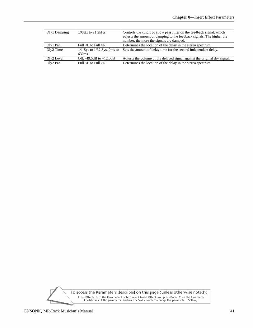
Chapter 8—Insert Effect Parameters
To access the Parameters described on this page (unless otherwise noted):Press Effects, turn the Parameter knob to select Insert Effect, and press Enter. Turn the Parameter
knob to select the parameter, and use the Value knob to change the parameter's Setting.
ENSONIQ MR-Rack Musician’s Manual 41
Dly1 Damping 100Hz to 21.2kHz Controls the cutoff of a low pass filter on the feedback signal, whichadjusts the amount of damping to the feedback signals. The higher thenumber, the more the signals are damped.
Dly1 Pan Full <L to Full >R Determines the location of the delay in the stereo spectrum.Dly2 Time 1/1 Sys to 1/32 Sys, 0ms to
630msSets the amount of delay time for the second independent delay.
Dly2 Level Off, -49.5dB to +12.0dB Adjusts the volume of the delayed signal against the original dry signal.Dly2 Pan Full <L to Full >R Determines the location of the delay in the stereo spectrum.
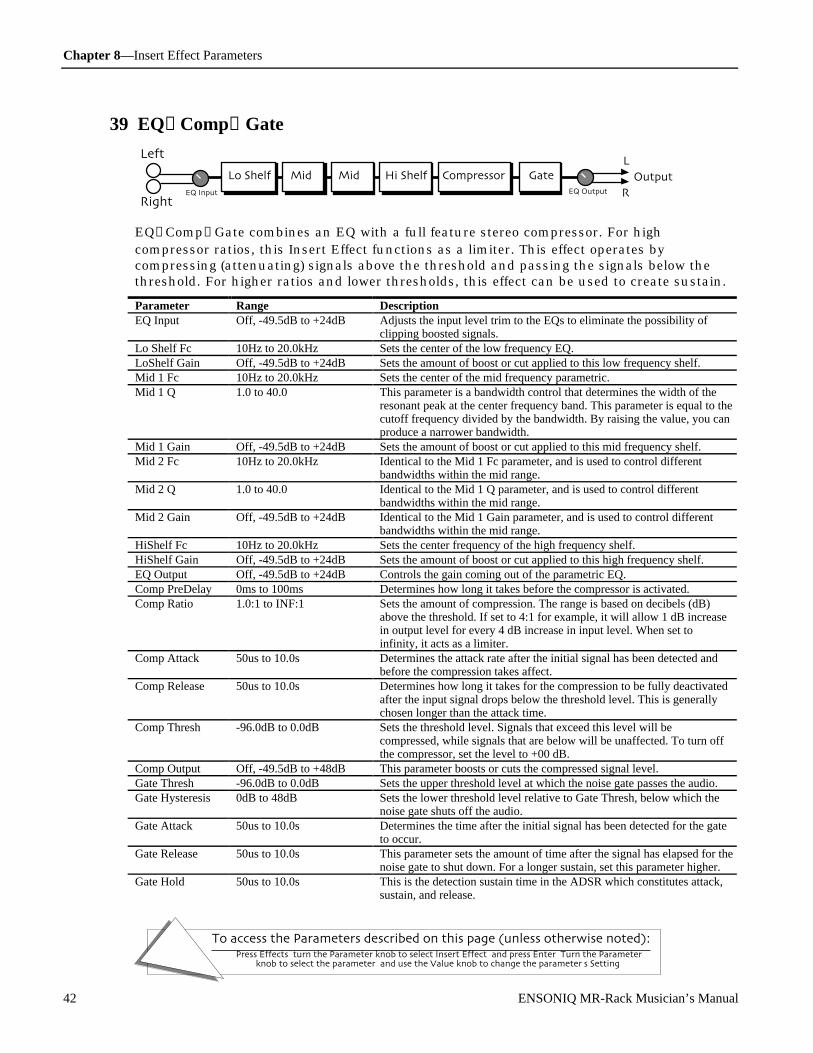
Chapter 8—Insert Effect Parameters
To access the Parameters described on this page (unless otherwise noted):Press Effects, turn the Parameter knob to select Insert Effect, and press Enter. Turn the Parameter
knob to select the parameter, and use the Value knob to change the parameter's Setting.
42 ENSONIQ MR-Rack Musician’s Manual
39 EQ→Comp→Gate
OutputLo Shelf
Right
Left
Mid 1L
REQ Input
Mid 2 Compressor GateEQ Output
Hi Shelf
EQ→Comp→Gate combines an EQ with a full feature stereo compressor. For highcompressor ratios, this Insert Effect functions as a limiter. This effect operates bycompressing (attenuating) signals above the threshold and passing the signals below thethreshold. For higher ratios and lower thresholds, this effect can be used to create sustain.
Parameter Range DescriptionEQ Input Off, -49.5dB to +24dB Adjusts the input level trim to the EQs to eliminate the possibility of
clipping boosted signals.Lo Shelf Fc 10Hz to 20.0kHz Sets the center of the low frequency EQ.LoShelf Gain Off, -49.5dB to +24dB Sets the amount of boost or cut applied to this low frequency shelf.Mid 1 Fc 10Hz to 20.0kHz Sets the center of the mid frequency parametric.Mid 1 Q 1.0 to 40.0 This parameter is a bandwidth control that determines the width of the
resonant peak at the center frequency band. This parameter is equal to thecutoff frequency divided by the bandwidth. By raising the value, you canproduce a narrower bandwidth.
Mid 1 Gain Off, -49.5dB to +24dB Sets the amount of boost or cut applied to this mid frequency shelf.Mid 2 Fc 10Hz to 20.0kHz Identical to the Mid 1 Fc parameter, and is used to control different
bandwidths within the mid range.Mid 2 Q 1.0 to 40.0 Identical to the Mid 1 Q parameter, and is used to control different
bandwidths within the mid range.Mid 2 Gain Off, -49.5dB to +24dB Identical to the Mid 1 Gain parameter, and is used to control different
bandwidths within the mid range.HiShelf Fc 10Hz to 20.0kHz Sets the center frequency of the high frequency shelf.HiShelf Gain Off, -49.5dB to +24dB Sets the amount of boost or cut applied to this high frequency shelf.EQ Output Off, -49.5dB to +24dB Controls the gain coming out of the parametric EQ.Comp PreDelay 0ms to 100ms Determines how long it takes before the compressor is activated.Comp Ratio 1.0:1 to INF:1 Sets the amount of compression. The range is based on decibels (dB)
above the threshold. If set to 4:1 for example, it will allow 1 dB increasein output level for every 4 dB increase in input level. When set toinfinity, it acts as a limiter.
Comp Attack 50us to 10.0s Determines the attack rate after the initial signal has been detected andbefore the compression takes affect.
Comp Release 50us to 10.0s Determines how long it takes for the compression to be fully deactivatedafter the input signal drops below the threshold level. This is generallychosen longer than the attack time.
Comp Thresh -96.0dB to 0.0dB Sets the threshold level. Signals that exceed this level will becompressed, while signals that are below will be unaffected. To turn offthe compressor, set the level to +00 dB.
Comp Output Off, -49.5dB to +48dB This parameter boosts or cuts the compressed signal level.Gate Thresh -96.0dB to 0.0dB Sets the upper threshold level at which the noise gate passes the audio.Gate Hysteresis 0dB to 48dB Sets the lower threshold level relative to Gate Thresh, below which the
noise gate shuts off the audio.Gate Attack 50us to 10.0s Determines the time after the initial signal has been detected for the gate
to occur.Gate Release 50us to 10.0s This parameter sets the amount of time after the signal has elapsed for the
noise gate to shut down. For a longer sustain, set this parameter higher.Gate Hold 50us to 10.0s This is the detection sustain time in the ADSR which constitutes attack,
sustain, and release.

Chapter 8—Insert Effect Parameters
To access the Parameters described on this page (unless otherwise noted):Press Effects, turn the Parameter knob to select Insert Effect, and press Enter. Turn the Parameter
knob to select the parameter, and use the Value knob to change the parameter's Setting.
ENSONIQ MR-Rack Musician’s Manual 43
40 EQ→Chorus→DDL
Lo Shelf Mid 1 Mid 2 Hi Shelf Output
L
R
4-Tap DDLStereo Chorus
Right
Left
EQ Input
A guitar-based effect chain that features a four-band parametric EQ, chorus, and fourdiscrete delays.
Parameter Range DescriptionEQ Input Off, -49.5dB to +24dB Adjusts the input level trim to the EQs to eliminate the possibility of
clipping boosted signals.LoShelf Fc 10Hz to 20.0kHz Sets the center of the low frequency EQ.LoShelf Gain Off, -49.5dB to +24dB Sets the amount of boost or cut applied to this low frequency shelf.Mid 1 Fc 10Hz to 20.0kHz Sets the center of the mid frequency parametric.Mid 1 Q 1.0 to 40.0 This parameter is a bandwidth control that determines the width of the
resonant peak at the center frequency band. This parameter is equal tothe cutoff frequency divided by the bandwidth. By raising the value, youcan produce a narrower bandwidth.
Mid 1 Gain Off, -49.5dB to +24dB Sets the amount of boost or cut applied to this mid frequency shelf.Mid 2 Fc 10Hz to 20.0kHz Identical to the Mid 1 Fc parameter, and is used to control different
bandwidths within the mid range.Mid 2 Q 1.0 to 40.0 Identical to the Mid 1 Q parameter, and is used to control different
bandwidths within the mid range.Mid 2 Gain Off, -49.5dB to +24dB Identical to the Mid 1 Gain parameter, and is used to control different
bandwidths within the mid range.HiShelf Fc 10Hz to 20.0kHz Sets the center frequency of the high frequency shelf.HiShelf Gain Off, -49.5dB to +24dB Sets the amount of boost or cut applied to this high frequency shelf.EQ Output Off, -49.5dB to +24dB Controls the gain coming out of the parametric EQ.Dry Blend Full Dry to Full Wet Controls the amount of the dry signal.LFO Rate 1/1 Sys to 1/32 Sys, 0.0Hz
to 20.0HzControls the four rates of the modulation applied to the delay time of thechorus.
Chorus Depth 0.0ms to 25.0ms Controls the amount of modulation.Chorus Center 0.0ms to 50.0ms Controls the four delay times within the chorus. Adjusting this
parameter will change the tonal character of the chorus.Dly1 Time 1/1 Sys to 1/32 Sys, 0ms to
630msSets the amount of delay time for the first independent delay.
Dly1 Level Off, -49.5dB to +12.0dB Adjusts the volume of the delayed signal against the original dry signal.Dly1 Feedback -99% to +99% Determines the amount of signal that will be fed from the output back
into the input, increasing the number of repeats in the delay.Dly1 Damping 100Hz to 21.2kHz Controls the cutoff of a low pass filter on the feedback signal, which
adjusts the amount of damping to the feedback signals. The higher thenumber, the more the signals are damped.
Dly1 Pan Full <L to Full >R Determines the location of the delay in the stereo spectrum.Dly2 Time 1/1 Sys to 1/32 Sys, 0ms to
630msSets the amount of delay time for the second independent delay.
Dly2 Level Off, -49.5dB to +12.0dB Adjusts the volume of the delayed signal against the original dry signal.Dly2 Feedback -99% to +99% Determines the amount of signal that will be fed from the output back
into the input, increasing the number of repeats in the delay.Dly2 Damping 100Hz to 21.2kHz Controls the cutoff of a low pass filter on the feedback signal, which
adjusts the amount of damping to the feedback signals. The higher thenumber, the more the signals are damped.
Dly2 Pan Full <L to Full >R Determines the location of the delay in the stereo spectrum.Dly3 Time 1/1 Sys to 1/32 Sys, 0ms to
630msSets the amount of delay time for the third independent delay.
Dly3 Level Off, -49.5dB to +12.0dB Adjusts the volume of the delayed signal against the original dry signal.
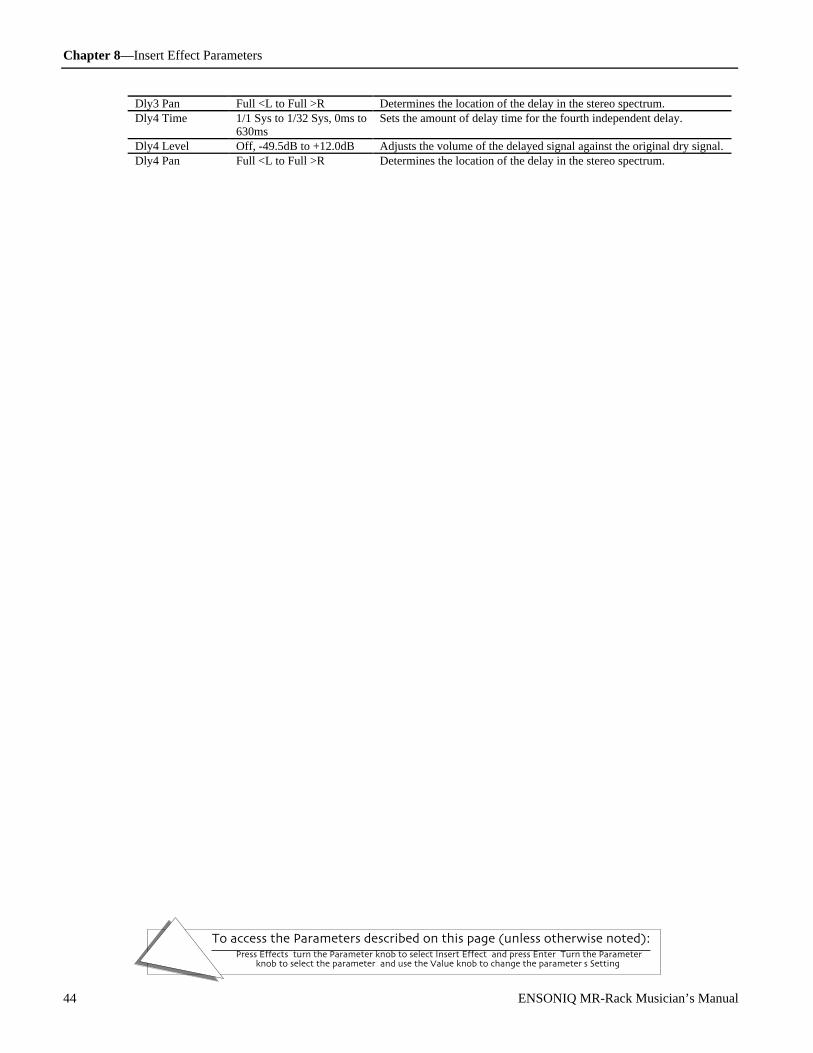
Chapter 8—Insert Effect Parameters
To access the Parameters described on this page (unless otherwise noted):Press Effects, turn the Parameter knob to select Insert Effect, and press Enter. Turn the Parameter
knob to select the parameter, and use the Value knob to change the parameter's Setting.
44 ENSONIQ MR-Rack Musician’s Manual
Dly3 Pan Full <L to Full >R Determines the location of the delay in the stereo spectrum.Dly4 Time 1/1 Sys to 1/32 Sys, 0ms to
630msSets the amount of delay time for the fourth independent delay.
Dly4 Level Off, -49.5dB to +12.0dB Adjusts the volume of the delayed signal against the original dry signal.Dly4 Pan Full <L to Full >R Determines the location of the delay in the stereo spectrum.

Chapter 9—Supplemental Information
ENSONIQ MR-Rack Musician’s Manual 1
Glossary
Alt. FX Bus The “second-choice” Effect Bus routing for Sounds routed to the Insert Effect bus. Also analternate term for the FX Bus parameter of any Sound not routed to the Insert Effect bus. In the MRUnisyn editor, the Alt. FX Bus is the means by which a Sound’s Effect routing is programmedwhen it’s not being routed to the Insert or Dry Effect busses.
Ambience The sound of the physical space—real or simulated—in which a sound occurs.
Amplify To increase the level, or loudness, of a signal.
Amplitude The level, or loudness, of a signal.
AO-C8 The MIDI pitch range of an 88-note keyboard. The lowest note is an A, designated as “A0,” andthe highest note, a C, is referred to as “C8.” The numbers increment at each C—A0 is followed byA#0, B0 and C1, for example. Middle C is “C4.” Most MIDI manufacturers use this scheme;however, a few manufacturers refer to Middle C as “C3.”
Attenuate To decrease the level, or loudness, of a signal.
Balanced-Line Input Three-conductor balanced lines are used to interconnect various pieces of equipment, and areoften used in professional studios. These balanced-line inputs tend to reject hum and/or radiofrequency interference. The MR-Rack has balanced-line outputs, for connecting with professionalbalanced-line input studio equipment.
Bandwidth The overall frequency spectrum of a Sound or Effect, measured in Hertz (Hz) and kiloHertz (kHz).
Bank A group of MR-Rack Sounds and Performances. There can be up to 127 Sounds in a bank, or up to32 Performances. Banks can be selected via MIDI with a Bank Select MSB of 0 followed by aBank Select LSB value specifying the number of the desired bank. MIDI Program Changemessages can select individual Sounds or Performances from within the chosen bank.
Bank Select A MIDI message pair which allows the remote selection of banks of MR-Rack Sounds andPerformances. A Bank Select message pair is comprised of an MSB value of 0 followed by an LSBvalue specifying the desired bank.
Buffer An area within the MR-Rack’s memory which temporarily stores changes made to a Performance,including Part Sound selection, Part parameter edits, Effect routings, Effect edits and PerfEditKitedits. These changes become permanent only when they are written to the MR-Rack’s memoryusing a Save command.
C4 The MIDI designation for Middle C on a MIDI keyboard or controller. Note: some MIDImanufacturers refer to Middle C as “C3.”
Chorusing An audio effect that results from the mixing together of a source signal with slightly delayedcopies of itself where the delay time of the copies is fluctuating in a regular, rhythmic fashion. Thetiming variations create phasing anomalies that cause the source signal to swirl, and sound widerand/or bigger.
Compression A sound-conditioning process that reduces a source signal’s dynamic range. Loud signals getsofter and softer signals get louder.
Compression Ratio The amount by which a signal is compressed, expressed as a ratio. For example, a 4 to 1compression ratio will result in an increase of 1dB in output level for every 4dB increase in inputlevel. At high ratios (such as 20:1 and above), the compressor acts as a limiter.
CTRL Synonym for “System Controller.”
Cutoff Frequency The filter setting that determines which frequencies a filter will leave un-attenuated. In a low-passfilter, the cutoff frequency setting determines the highest frequency that will be allowed to passthrough the filter. In a high-pass filter, it determines the lowest frequency.
Cycle A sound wave’s single journey from exerting a greater amount of air pressure to a lesser one andback to its starting point. The number of cycles per second determines the pitch—orfrequency—of the sound wave. The number of cycles per second is expressed in Hertz (Hz) andkiloHertz (kHz).
Damping A reverb parameter that determines how quickly the high-frequency content of a reverb will bereduced as it decays to silence.
DDL Abbreviation for “digital delay line,” an Effect that creates a digital copy, or copies, of a sourcesignal and plays it (or them) back later than the original signal. These delays can be used tocreate a myriad of audio effects.

Chapter 9—Supplemental Information
2 ENSONIQ MR-Rack Musician’s Manual
Diffusion A reverb parameter used to smear a reverb’s transients in order to smooth the reverb’s sound.Low diffusion values will cause transients to appear as a series of discrete echoes, while highervalues tend to increase the blurring effect for a smoother sound.
Drum Kit Sound A special type of Sound in which each of the 64 keys from B1 to D4 points to and plays its ownstandard MR-Rack Sound. Each key in a Drum Kit Sound—called a “DrumKey”—has its ownPart parameters.
DrumKey Any of the keys from B1 to D4 when a Drum Kit Sound is selected. Each DrumKey plays astandard MR-Rack Sound and has its own Part parameters.
Dry The Effect description for a Sound not routed to any of the MR’s Effects.
Early Reflections(ER)
Early reflections are delayed signals that aurally suggest the size of ambient spaces. In the realworld, sound bounces off surfaces it encounters—walls, ceiling and floor. Quick early reflectionssuggest small spaces, with these surfaces close by. Longer early reflections imply to the ear thatthe surfaces are farther away, and that the ambient space is therefore larger.
Effect Signal processing typically applied to Sounds as a final touch. Many Effects simulate ambiencesof a realistic or fantastic nature. Effects include reverbs, delays, choruses, flangers, phasers,distortion and so on. Every MR-Rack Performance offers an Effects set-up comprised of a GlobalChorus, a Global Reverb and an Insert Effect of your choosing.
Envelopes Devices which allow the shaping of Sounds and Effects.
Equalization (EQ) The process of altering the frequency content of a sound. Everything we hear is comprised of anumber of sound waves occurring at the same time, at different pitches, or “frequencies.”Equalization allows you to change the volume balance of the frequencies within a sound.
Feedback A signal routing in which the output of an Effect is mixed back into the input. Feedback of adelay line is also called regeneration.
Filter A device that attenuates selected frequencies within a Sound or Effect. For example, a high-passfilter passes all signals higher than a selected frequency, attenuating all those frequencies belowit. A low-pass filter passes all signals below a selected frequency, attenuating all thosefrequencies above it.
Flanger A processor that simulates the effect of two synchronized tape machines playing back the samesignal, with the speed of one machine being slowed slightly by the gentle pressing on the outershell—or “flange”—of one of its tape reels. This small amount of delay causes a phasingcancellation that filters out elements of the Sound being processed. Changing the delay timecauses the “flange” effect. In the MR-Rack, flanging is achieved using interpolated digital delaylines.
Frequency The number of times per second that a sound wave repeats its excursion from maximumcompression of air pressure to minimum compression and back to its starting point—eachexcursion is called a cycle. The number of cycles per second is expressed in Hertz (Hz) andkiloHertz (kHz). Lower frequencies produce lower pitches and higher frequencies produce higherpitches. Sounds are comprised of a number of sound waves of varying frequencies occurring atroughly the same time. “Frequency” may be used as shorthand for one of those sound waves, or“frequencies” for a group of them.
Gate (Noise Gate) A device that attenuates a source signal falling below a pre-determined volume threshold. Auseful tool in eliminating noise and controlling signals that use an effect. Ambiences such asreverb may be gated to produce an extreme and artificial-sounding decay.
Global The MR-Rack uses this word in two senses: 1. System-wide settings which affect all Sounds,Parts, Performances and Effects in the MR-Rack. 2. the Chorus and Reverb Effects which areavailable in any Performance, referred to as “Global Chorus” and “Global Reverb.”
Hysteresis The property of a system whose behavior is determined by the level, direction, and history of acontrolling signal. Used in the MR-Rack to provide greater control over gating, triggering, andcompression.
Layer The MR-Rack uses this word in two senses: 1. a set of digital sound recordings—orsamples—that span the entire MIDI pitch range, and their associated parameters. Up to 16 ofthese can be combined to create an MR-Rack Sound. 2. to pile Sounds “on top of each other” byassigning multiple Parts to the same MIDI channel or the Stak channel, causing the Sounds toplay simultaneously in response to the MIDI notes received on their common MIDI channel.
LED LEDs (Light Emitting Diodes) are small solid-state lamps found embedded in a number of theMR-Rack’s buttons. Under normal conditions, they have a virtually unlimited lifetime.
LFO An oscillator which generates sound waves at a frequency below the audio spectrum. These low-frequency waves can modulate audible sound waves to produce vibrato, tremolo, and othereffects. LFOs can also be employed to produce rhythmic changes in various Effects.
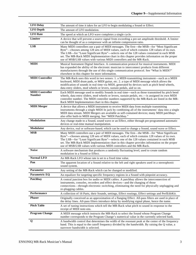
Chapter 9—Supplemental Information
ENSONIQ MR-Rack Musician’s Manual 3
LFO Delay The amount of time it takes for an LFO to begin modulating a Sound or Effect.
LFO Depth The amount of LFO modulation.
LFO Rate The speed at which an LFO wave completes a single cycle.
Limiter A device that will prevent a source signal from exceeding a pre-set amplitude threshold. A limitercan be thought of as a compressor with an infinite compression ratio.
LSB Many MIDI controllers use a pair of MIDI messages. The first—the MSB—for “Most SignificantByte”—chooses among 128 sets of MIDI values, each of which contains 128 values of its own.The LSB—for “Least Significant Byte”—selects one of the 128 values contained in each MSBset. The MR-Rack MIDI Implementation chart in this chapter provides information on the properuse of MSB/LSB values with various MIDI controllers and the MR-Rack.
MIDI Musical Instrument Digital Interface. A communication protocol for musical instruments. MIDIhas expanded the ability of the electronic musician to interconnect products from differentmanufacturers through the use of this single communication protocol. See “What Is MIDI?”elsewhere in this chapter for more information.
MIDI Controller The MR-Rack uses this word in two senses: 1. a MIDI-transmitting instrument—such as a MIDIkeyboard, MIDI drum pads, or MIDI guitar, etc. 2. a type of MIDI message which allows themodification of sounds in real time via MIDI, generated by devices such as pitch bend wheels,data entry sliders, mod wheels or levers, sustain pedals, and so on.
MIDI ControllerNumber
Each MIDI message used to modify Sounds in real time—such as those transmitted by pitch bendwheels, data entry sliders, mod wheels or levers, sustain pedals, etc.—is assigned its own MIDIcontroller number. The MIDI controller numbers supported by the MR-Rack are listed in the MR-Rack MIDI Implementation chart in this chapter.
MIDI Merger A device that allows a MIDI instrument to receive MIDI data from multiple transmittinginstruments through a single MIDI In jack by combining all of the instruments’ data into a singleMIDI data stream. MIDI Mergers are available as self-contained devices; many MIDI patchbaysalso offer built-in MIDI merging. See “MIDI Patchbay.”
Modulation Any change made to a Sound, sound wave or an Effect, either through pre-programmed automaticdevices or real-time manual manipulation.
Modulator Any device, real or software-based, which can be used to change a Sound, sound wave or Effect.
MSB Many MIDI controllers use a pair of MIDI messages. The first—the MSB—for “Most SignificantByte”—chooses among 128 sets of MIDI values, each of which contains 128 values of its own.The LSB—for “Least Significant Byte”—selects one of the 128 values contained in each MSBset. The MR-Rack MIDI Implementation chart in this chapter provides information on the properuse of MSB/LSB values with various MIDI controllers and the MR-Rack.
Noise A software mechanism that produces a randomly fluctuating level, used to create randommodulation in a Sound or Effect.
Normal LFO An MR-Rack LFO whose rate is set to a fixed time value.
Pan The apparent location of a Sound relative to the left and right speakers used in a stereophonicsound system.
Parameter Any setting of the MR-Rack which can be changed or modified.
Parametric EQ An equalizer for targeting specific frequency regions in a Sound with pinpoint accuracy.
Patchbay A central junction box for audio or MIDI cables. A patchbay allows the interconnection ofinstruments, consoles, recorders and effect devices—and the changing of thoseconnections—through electronic switching, eliminating the need for physically unplugging andre-plugging cables.
Performance A collection of 16 Parts, their Sounds, settings, Effect routings, Effect settings and PerfEditKit.
Phaser Originally conceived as an approximation of a flanging Effect. All-pass filters are used in place ofthe delay lines. All-pass filters introduce delay by modifying signal phase, hence the name.
Pitch Table A set of tuning instructions which tell the MR-Rack what pitch to sound in response to thereceipt of MIDI note-ons.
Program Change A MIDI message which instructs the MR-Rack to select the Sound whose Program Changenumber corresponds to the Program Change’s numerical value in the currently selected bank.
Q A bandwidth control that determines the width of the resonant peak at the center of the frequencyband. This is equal to the cutoff frequency divided by the bandwidth. By raising the Q value, anarrower bandwidth is selected.
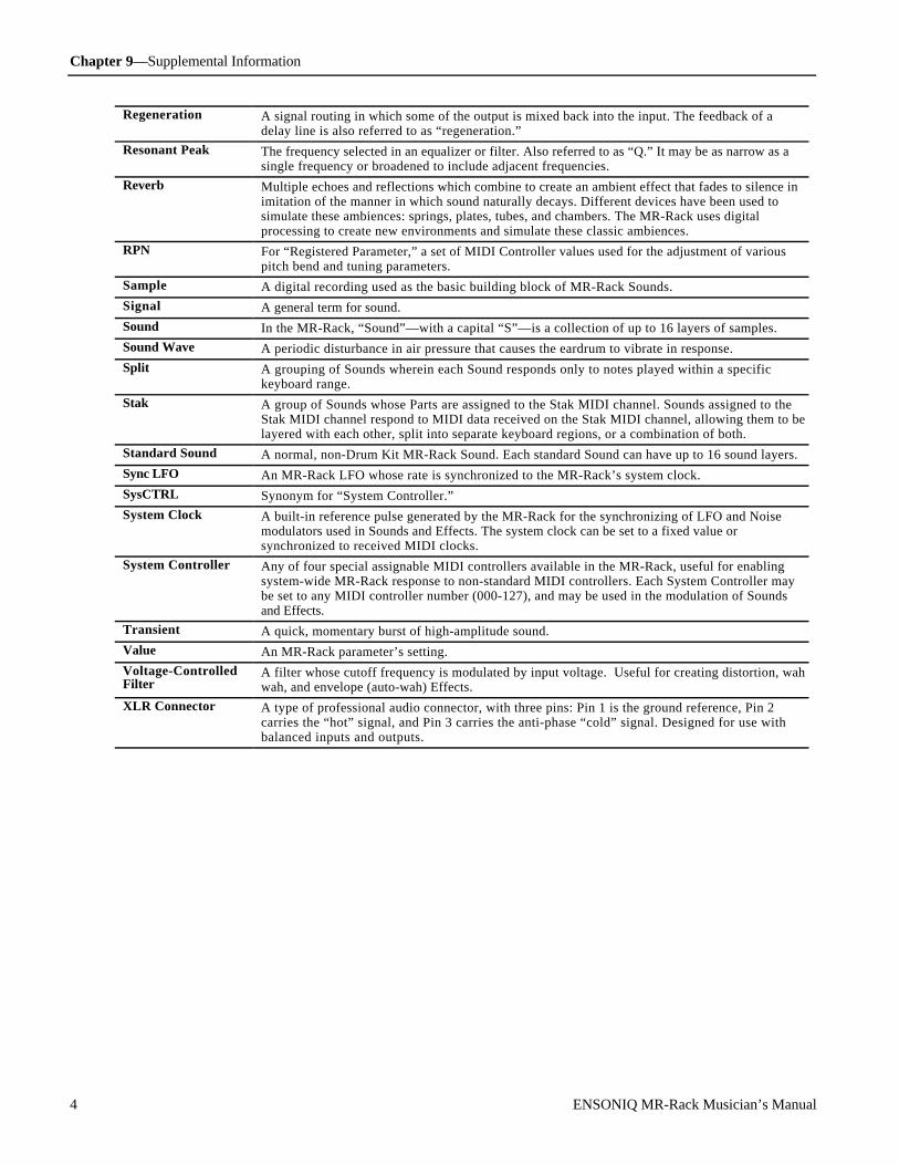
Chapter 9—Supplemental Information
4 ENSONIQ MR-Rack Musician’s Manual
Regeneration A signal routing in which some of the output is mixed back into the input. The feedback of adelay line is also referred to as “regeneration.”
Resonant Peak The frequency selected in an equalizer or filter. Also referred to as “Q.” It may be as narrow as asingle frequency or broadened to include adjacent frequencies.
Reverb Multiple echoes and reflections which combine to create an ambient effect that fades to silence inimitation of the manner in which sound naturally decays. Different devices have been used tosimulate these ambiences: springs, plates, tubes, and chambers. The MR-Rack uses digitalprocessing to create new environments and simulate these classic ambiences.
RPN For “Registered Parameter,” a set of MIDI Controller values used for the adjustment of variouspitch bend and tuning parameters.
Sample A digital recording used as the basic building block of MR-Rack Sounds.
Signal A general term for sound.
Sound In the MR-Rack, “Sound”—with a capital “S”—is a collection of up to 16 layers of samples.
Sound Wave A periodic disturbance in air pressure that causes the eardrum to vibrate in response.
Split A grouping of Sounds wherein each Sound responds only to notes played within a specifickeyboard range.
Stak A group of Sounds whose Parts are assigned to the Stak MIDI channel. Sounds assigned to theStak MIDI channel respond to MIDI data received on the Stak MIDI channel, allowing them to belayered with each other, split into separate keyboard regions, or a combination of both.
Standard Sound A normal, non-Drum Kit MR-Rack Sound. Each standard Sound can have up to 16 sound layers.
Sync LFO An MR-Rack LFO whose rate is synchronized to the MR-Rack’s system clock.
SysCTRL Synonym for “System Controller.”
System Clock A built-in reference pulse generated by the MR-Rack for the synchronizing of LFO and Noisemodulators used in Sounds and Effects. The system clock can be set to a fixed value orsynchronized to received MIDI clocks.
System Controller Any of four special assignable MIDI controllers available in the MR-Rack, useful for enablingsystem-wide MR-Rack response to non-standard MIDI controllers. Each System Controller maybe set to any MIDI controller number (000-127), and may be used in the modulation of Soundsand Effects.
Transient A quick, momentary burst of high-amplitude sound.
Value An MR-Rack parameter’s setting.
Voltage-ControlledFilter
A filter whose cutoff frequency is modulated by input voltage. Useful for creating distortion, wahwah, and envelope (auto-wah) Effects.
XLR Connector A type of professional audio connector, with three pins: Pin 1 is the ground reference, Pin 2carries the “hot” signal, and Pin 3 carries the anti-phase “cold” signal. Designed for use withbalanced inputs and outputs.

Chapter 9—Supplemental Information
ENSONIQ MR-Rack Musician’s Manual 1
Ch apt e r 9Su ppl e m en t al I nf or m at ion
This section contains additional information that you will find helpful in fully understandingthe MR-Rack and its abilities.
List of SoundF inde r Type s
Performance TypesThe following is a list of the MR-Rack Performance Types. If there are no Performances of aparticular type, the type will not appear in the list. Performances will appear in numericalorder within each type:
CRD-PERF Performances found on a PCMCIA card
EXP-PERF Expansion board Performances
GM-PERF General MIDI-based Performances
ROM-PERF Performances stored in ROM memory.
RAM-PERF Performances stored in RAM memory.
ALL-PERF All Performances, in alphabetical order
Sound TypesHere is a list of the available SoundFinder Sound types. If there are no Sounds of aparticular type, the type will not appear in the list of types:
USER-SND Sound Type for Sounds that you want quick access to. These Sounds also appear in their appropriateSoundFinder musical instrument type list.
DEMO-SND Demo sounds are designed to demonstrate the scope of Sounds in the MR-Rack. Whenever this isselected, the first Sound in the type will be selected the MR-Rack will not reselect the last Soundselected in the Demo type. Demo Sounds also appear in their appropriate Sound Type list.
CRD-SND PCMCIA card Sounds.EXP-SND Expansion board Sounds.DRM-SND ROM drum key Sounds.GM-SND Includes both ROM General MIDI Sounds, and GM/GS Drum Kit SoundsROM-SND All Sounds in ROM.RAM-SND All RAM Sounds.ALL-SND All Sounds. The PerfEditKit appears in ALL-SND.BASS Acoustic and electric basses.BASS-SYN Synth basses, and processed electric basses with a “synthy” quality.BELL Acoustic and synth bell Sounds, both pitched (e.g., glockenspiel, celesta). and non-pitched (e.g., church
bells).BRASSECT Trumpet, trombone, tuba, French horn, saxophone, and mixed brass sections (including sampled
sections) and small ensembles (with more than one distinct pitch/“player” on a single key).BRASSOLO Solo brass (e.g., trumpet, trombone, tuba, French horns).DRUM-KIT Drum kits that use the ENSONIQ Drum Map.DRMKITGM Drum kits that use the General MIDI Drum Map.GUITAR-A Steel, nylon, and gut-stringed acoustic guitars.GUITAR-E Clean electric guitars and distortion guitars.HITS Orchestra hits.KEYS Other stringed keyboard Sounds (e.g., harpsichord and clavinet).

Chapter 9—Supplemental Information
2 ENSONIQ MR-Rack Musician’s Manual
LAYERS Unnatural layered combinations of acoustic elements (e.g., a bass harmonic layered with a stringsection), excluding pianos/electric-pianos/organs layered with other Sounds in which the piano/electric-piano/organ element is dominant. Also excludes multi-instrumental orchestral layers.
LOOPGRUV Looped, repeating musical passages and drum rhythm loops (sampled or wave-sequenced) that play onone key.
MALLET Tuned mallet-struck percussion instruments (e.g., marimba, xylophone, timpani, steel drum, log drum).ORCHSTRA Multi-instrumental orchestral Sounds (e.g., mixed strings/brass/ woodwinds/reeds/orchestral
percussion) layered with one another.ORGAN-A Acoustic pipe and pump organs.ORGAN-E Electric and electronic organs.ORGANLYR Any organs layered with other Sounds in which the organ element is dominant.PERC-KIT Percussion kits that use either the ENSONIQ or General MIDI Percussion Maps.PERCSOLO Solo untuned percussion (e.g., taiko, synth-tom) includes most drum key Sounds.PIANO-A Acoustic pianos, honky-tonk, toy pianos, and piano forte.PNOLYR-A Acoustic pianos layered with other Sounds in which the acoustic piano element is dominant.PIANO-E Electric and electronic piano Sounds, and electric pianos layered with acoustic pianos.PNOLYR-E Electric pianos layered with other Sounds in which the electric piano element is dominant.PLUCKED Plucked strings (e.g., harps, banjo, dulcimer, sitar), pizzicato strings, and other plucked instruments
(e.g., kalimba).SAX-SOLO Solo saxophones.SOUND-FX Realistic sound effects (e.g., broken glass, animal sounds, record scratches) and entirely non-pitched
fantasy and chaos sound effects.(e.g., spacecraft, environments)SPLITS Combination keyboard splits of two or more different types of Sounds. Also includes splits of similar
sounds that have discontiguous key ranges (e.g., a bassoon/oboe split that covers the natural ranges ofboth instruments).
STRGSECT Bowed string sections (including sampled sections) and small string ensembles (with more than onedistinct pitch/“player” on a single key).
STRGSOLO Bowed solo strings (e.g., violin, viola, cello).SYN-COMP Non-vintage, sustaining and non-sustaining, polyphonic synth Sounds with a pitched or non-pitched,
highly obtrusive attack component that lend themselves toward comping (i.e., you can always playsuccessive 1/8 note chords with these funky sounds).
SYN-LEAD Monophonic lead synth Sounds (excluding monophonic synth basses).SYN-PAD Non-vintage, sustaining, polyphonic synth Sounds with a pitched, less obtrusive attack component, and
an appropriate release, that lend themselves toward pad playing.SYN-VINT Polyphonic, signature vintage “analog” synth Sounds (excluding monophonic vintage synth leads and
synth basses). Normally these are named after the synth that they evoke.SYNOTHER Other types of pitched, polyphonic, hybrid synth Sounds with sustaining, disparate components (e.g.,
sample & hold sync Sounds).VOCALS Vocal Sounds (e.g., choirs, synth-vox).WINDREED Solo woodwinds/reeds (e.g., flute, oboe, bassoon, clarinet, recorder, English horn, ocarina, bandneon,
shakuhachi, bagpipes, harmonica, accordion, melodica, didjeridoo).*UTILITY Utility resources (e.g., default template Sounds used for programming and other special non-musical
purposes).*CUSTOM Use this type to define your own special purpose Sounds when created with external computer-based
sound editing software. The PerfEditKit will always be assigned to CUSTOM. ENSONIQ sounds willnever be released with a type of CUSTOM.

Chapter 9—Supplemental Information
ENSONIQ MR-Rack Musician’s Manual 3
List of Wave N am e s and C las ses Here is a list of the waves found within the MR-Rack voice architecture:
KEYBOARD BRASS+HORNS DRUM-SOUND PERCUSSION WAVEFORMGRAND PIANO TRUMPET ACOUSTC KICK AGOGO SAWTOOTHGRAND MED HI MUTE TRUMPET BIG KICK BONGO SINE WAVEGRAND MED LO FLUGELHORN BOOM KICK CABASA SQUARE WAVEGRAND SOFT SOLO FR HORN BRIGHT KICK CASTANETS TRIANGLE WAVEPIANO THUD TROMBONE DANCE KICK CLAVE ANALOG WV 1PNO HAMMER UP POP BRASS SEC ELEC KICK CLICK ANALOG WV 2PNO HARP NOIS FR HORN SECT FAT KICK CONGA HIGH ANALOG WV 3TINE EPNO A SYNTH BRASS GATED KICK CONGA LOW ANALOG WV 4TINE EPNO B JAZZ KICK CONGA MUTE ANALOG WV 5TINE EPNO C WIND+REEDS LOOP KICK COWBELL ANALOG WV 6TINE EPNO D TENOR SAX MUFF KICK COWBELL STICK ANALOG WV 7TINE EPNO E ALTO SAX PROCESSD KICK CUICA ANALOG WV 8TINE EPNO F SOPRANO SAX PUNCHY KICK FINGER SNAPS DIGITAL WV 1DIGI PIANO SAX AIR RAP KICK GUIRO DIGITAL WV 2DIGI PNO SOFT CHIFF REAL KICK HANDCLAPS BELL WAVE 1FM EPNO A CHIFFLUTE RESO KICK JAWHARP BELL WAVE 2FM EPNO B FLUTE SYNTH KICK 1 MARACAS BELL WAVE 3FM EPNO C OCARINA SYNTH KICK 2 SHAKER BELL WAVE 4FM EPNO D PAN FLUTE TIGHT KICK SLEIGHBELL BELL WAVE 5WURLIE HIVEL OBOE COM/GATE SNR SPOONS BELL WAVE 6WURLIE LOVEL ENGLISH HORN CONCERT SNARE TAIKO BELL WAVE 7HARPSICHORD BASSOON CRACK SNARE TAMBOURINE BIG BELL WFCLAVINET CLARINET DANCE SNARE TIMBALI SYNTH BELLFM CLAV ACCORDION 1 ELEC SNARE TRIANGLE VOCAL WF 1CELESTE ACCORDION 2 GATED POP SNR VIBRASLAP VOCAL WF 2ORG-775305004 HARMONICA GM SNARE 1 WHISTLE VOCAL WF 3ORG-845351402 CONCH SHELL HIPHOP SNARE WOODBLOCK VOCAL WF 4ORG-875434578 RECORDER POP SNARE SYN CLAPS VOCAL WF 5ORG-875645332 RAP SNARE SYN COWBELL VOCAL WF 6ORG-888000000 VOCAL-SOUND REAL SNARE SYN MARACAS DOUBLE REEDORG-888808008 VOCAL AAHS RIMSHOT SYNTH CLAVE REED WFORG-888856444 VOCAL OOHS ROCK SNARE SYNTH KISS SINGLE REEDORG-888880880 BREATHY OOH SYNTH SNARE WIND CHIME PIANO BS WFORGAN WAVE 1 SYNTH VOX AAH SNARE ROLL CACTUS LOOP PIANO WFORGAN WAVE 2 VOCAL AIR SIDESTICK 1 NUT RATTLE LP E-BASS WF 1PERC ORGAN 1 DOO ATTACK SIDESTICK 2 RAINSTICK E-BASS WF 2PERC ORGAN 2 STICK CLICKROTARY ORGAN BASS-SOUND BRUSH HIT TUNED-PERC INHARMONICSYNKEY WAVE STANDUP BASS BRUSH SLAP VIBRAPHONE NOISECHURCH ORGAN STANDUP BS 2 BRUSH SWISH MARIMBA SPECTRUMPIPE ORGAN STANDUP BS 3 BRUSH TAP XYLOPHONE AIR LOOPREED ORGAN FRETLESS BASS BRUSH TOM LOG DRUM BIG BELLCLINK FINGER BASS 1 DRY TOM KALIMBA CRYSTALORG KEYCLICK FINGER BASS 2 ROOM TOM STEEL DRUM TEXTUREMOOG LEAD FINGER BASS 3 SYNTH DRUM DOORBELLPAD SYNTH PICK BASS 1 SYNTH RIM GAMELAN BELL TRANSWAVE
PICK BASS 2 GLOCKENSPIEL AAH OOH XWSTRING-SOUND MUTED BASS CYMBALS HANDBELLS ANA BS XWAVENYLON GUITAR SLAP BASS 1 CLOSED HAT 1 SM TUNED GONG ANA VOX-XNYLON GTR SOFT SLAP BASS 2 CLOSED HAT 2 TUBULAR ANALOG PAD XSTEEL GUITAR BASS POP NOIS CLOSED HAT 3 TYMPANI BELL XWAVE 1STEEL GTR SOFT BS HARMONICS SYN CLOSEHAT DANCE HIT BELL XWAVE 2FRET NOISE EL BASS TAP RAP HAT 1 ORCH HIT BELL XWAVE 3EL GUITAR 1 ANALOG BS 1 RAP HAT 2 BELL XWAVE 4EL GTR 1 SOFT ANALOG BS 2 OPEN HAT SOUND-EFFECT DRAWBAR XWEL GUITAR 2 ANALOG BS 3 SYN OPEN HAT APPLAUSE MELLOW SWEEPDIST GUITAR FM BASS 1 PEDAL HAT BIRD SONG MULTI BELLDIST GTR LOOP FM BASS 2 CRASH CYMBAL GUNSHOT ORGAN XWAVEFEEDBACK HARM GUITARRON RIDE CYMBAL HELICOPTER OSC SYNC XW 1GTR HARMONIC TUBE BASS RIDE BELL TELEPHONE OSC SYNC XW 2JAZZ GUITAR CHINA CRASH WIND CHIMES PHASE SYNCMUTE GUITAR SURFACE NOISE PULSE XMUTE GTR SOFT RAP BS XWAVECELLO RESONANCEVIOLIN REZ BS XWAVESTRING SECTION REZ SWEEPSTRING SECT B REZO-X 4STRING SECT C REZO-X 3PIZZ STRINGS REZO-X 2BANJO REZO-X 1HARP SCRATCH WAVEGOTO SOFT ANALOGSHAMISEN TECHNO BASSSITAR TINE XWAVE
TRANSWAVE AATRANSWAVE AHTRANSWAVE EETRANSWAVE OOTRANSWAVE ZTRI SWEEPWAKKA WAKKA
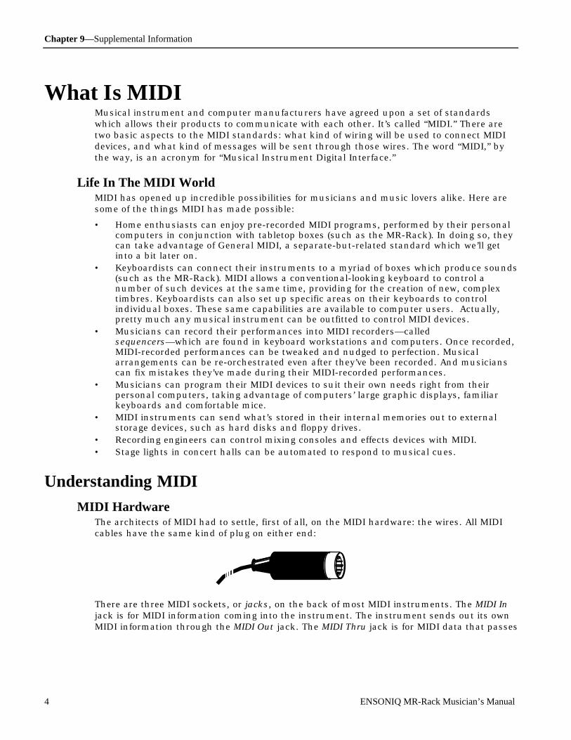
Chapter 9—Supplemental Information
4 ENSONIQ MR-Rack Musician’s Manual
What I s M IDI Musical instrument and computer manufacturers have agreed upon a set of standardswhich allows their products to communicate with each other. It’s called “MIDI.” There aretwo basic aspects to the MIDI standards: what kind of wiring will be used to connect MIDIdevices, and what kind of messages will be sent through those wires. The word “MIDI,” bythe way, is an acronym for “Musical Instrument Digital Interface.”
Life In The MIDI WorldMIDI has opened up incredible possibilities for musicians and music lovers alike. Here aresome of the things MIDI has made possible:
• Home enthusiasts can enjoy pre-recorded MIDI programs, performed by their personalcomputers in conjunction with tabletop boxes (such as the MR-Rack). In doing so, theycan take advantage of General MIDI, a separate-but-related standard which we’ll getinto a bit later on.
• Keyboardists can connect their instruments to a myriad of boxes which produce sounds(such as the MR-Rack). MIDI allows a conventional-looking keyboard to control anumber of such devices at the same time, providing for the creation of new, complextimbres. Keyboardists can also set up specific areas on their keyboards to controlindividual boxes. These same capabilities are available to computer users. Actually,pretty much any musical instrument can be outfitted to control MIDI devices.
• Musicians can record their performances into MIDI recorders—calledsequencers—which are found in keyboard workstations and computers. Once recorded,MIDI-recorded performances can be tweaked and nudged to perfection. Musicalarrangements can be re-orchestrated even after they’ve been recorded. And musicianscan fix mistakes they’ve made during their MIDI-recorded performances.
• Musicians can program their MIDI devices to suit their own needs right from theirpersonal computers, taking advantage of computers’ large graphic displays, familiarkeyboards and comfortable mice.
• MIDI instruments can send what’s stored in their internal memories out to externalstorage devices, such as hard disks and floppy drives.
• Recording engineers can control mixing consoles and effects devices with MIDI.• Stage lights in concert halls can be automated to respond to musical cues.
U nde r st anding MID I
MIDI HardwareThe architects of MIDI had to settle, first of all, on the MIDI hardware: the wires. All MIDIcables have the same kind of plug on either end:
There are three MIDI sockets, or jacks, on the back of most MIDI instruments. The MIDI Injack is for MIDI information coming into the instrument. The instrument sends out its ownMIDI information through the MIDI Out jack. The MIDI Thru jack is for MIDI data that passes

Chapter 9—Supplemental Information
ENSONIQ MR-Rack Musician’s Manual 5
through the instrument unchanged, on its way to some other MIDI device.
MIDI OutMIDI Thru MIDI In
The MIDI cable itself can carry 16 independent channels of MIDI information which traveltogether through the wire. This means that you can have 16 separate MIDI conversationsgoing on at once among instruments and/or computers connected together with MIDIcables.
How MIDI Channels WorkMIDI instruments can be set up to listen to specific channels and ignore everything elsethat’s going on. This allows a central device to control each instrument individually.
Instrument 9Instrument 8
Instrument 10
Instrument 11
Instrument 12Instrument 5
Instrument 6
Instrument 7
Instrument 1
Instrument 2
Instrument 3
Instrument 4
Instrument 16
Instrument 13
Instrument 14
Instrument 15
or
Some devices—such as the MR-Rack—are capable of responding to as many as 16 channelsat once. Such instruments are referred to as being multi-timbral—it’s as if there are up to 16musical instruments in one box, and MIDI allows you to control each sound separately.
Sound 13
Sound 12
Sound 14
Sound 11
Sound 15
Sound 16
or
Sound 1
Sound 2
Sound 3
Sound 4
Sound 7
Sound 6
Sound 8
Sound 5
Sound 9
Sound 10
MIDI rigs can also combine both possibilities, with some instruments programmed to
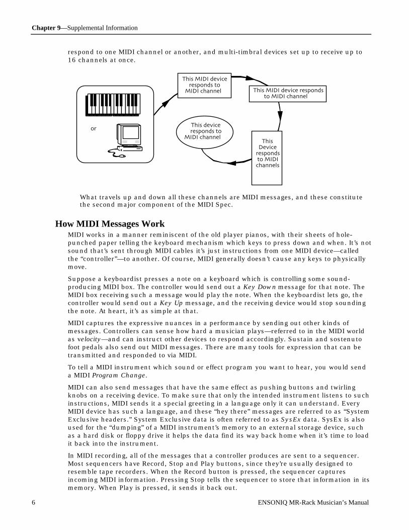
Chapter 9—Supplemental Information
6 ENSONIQ MR-Rack Musician’s Manual
respond to one MIDI channel or another, and multi-timbral devices set up to receive up to16 channels at once.
This MIDI deviceresponds to
MIDI channel 1
or
ThisDevice
respondsto MIDIchannels
3-15
This MIDI device respondsto MIDI channel 2
This deviceresponds to
MIDI channel 16
What travels up and down all these channels are MIDI messages, and these constitutethe second major component of the MIDI Spec.
How MIDI Messages WorkMIDI works in a manner reminiscent of the old player pianos, with their sheets of hole-punched paper telling the keyboard mechanism which keys to press down and when. It’s notsound that’s sent through MIDI cables it’s just instructions from one MIDI device—calledthe “controller”—to another. Of course, MIDI generally doesn’t cause any keys to physicallymove.
Suppose a keyboardist presses a note on a keyboard which is controlling some sound-producing MIDI box. The controller would send out a Key Down message for that note. TheMIDI box receiving such a message would play the note. When the keyboardist lets go, thecontroller would send out a Key Up message, and the receiving device would stop soundingthe note. At heart, it’s as simple at that.
MIDI captures the expressive nuances in a performance by sending out other kinds ofmessages. Controllers can sense how hard a musician plays—referred to in the MIDI worldas velocity—and can instruct other devices to respond accordingly. Sustain and sostenutofoot pedals also send out MIDI messages. There are many tools for expression that can betransmitted and responded to via MIDI.
To tell a MIDI instrument which sound or effect program you want to hear, you would senda MIDI Program Change.
MIDI can also send messages that have the same effect as pushing buttons and twirlingknobs on a receiving device. To make sure that only the intended instrument listens to suchinstructions, MIDI sends it a special greeting in a language only it can understand. EveryMIDI device has such a language, and these “hey there” messages are referred to as “SystemExclusive headers.” System Exclusive data is often referred to as SysEx data. SysEx is alsoused for the “dumping” of a MIDI instrument’s memory to an external storage device, suchas a hard disk or floppy drive it helps the data find its way back home when it’s time to loadit back into the instrument.
In MIDI recording, all of the messages that a controller produces are sent to a sequencer.Most sequencers have Record, Stop and Play buttons, since they’re usually designed toresemble tape recorders. When the Record button is pressed, the sequencer capturesincoming MIDI information. Pressing Stop tells the sequencer to store that information in itsmemory. When Play is pressed, it sends it back out.

Chapter 9—Supplemental Information
ENSONIQ MR-Rack Musician’s Manual 7
The Art of MIDIThe fact that MIDI is so simple to use is a testament to the cleverness of its designers. Itstrue magic, however, lies in MIDI’s power as a tool in the creative process, and in theimaginations of those artists who wield it.
What Is Ge ne r al M ID IGeneral MIDI is an agreed-upon set of sounds and protocols which aims to ensure that, nomatter what brand or model General MIDI instrument you use in conjunction with yourpersonal computer to play back a General MIDI recording, the music will sound essentiallythe same. General MIDI provides a tremendous convenience for listeners and multimediafans who want to enjoy MIDI-based music without having to delve too deeply into itsmechanics.
All General MIDI-supporting products sport the General MIDI logo:
General MIDI accomplishes its predictability by employing a very specific set of agreementson a number of MIDI issues.
General MIDI SoundsIn the larger MIDI universe, any sound may reside anywhere in an instrument’s memory, inthe General MIDI world, the same sounds always reside in the same-numbered memorylocations. This guarantees that if a programmer calls up a particular sound when he or sheprograms some General MIDI music, any time anyone anywhere plays that music back on aGeneral MIDI instrument, that same sound will be invoked. See “List of General MIDISounds” in this chapter for a full list of the General MIDI sounds.
General MIDI Drum KitsAnother important convention employed by General MIDI instruments are the General MIDIdrum maps. The GM drum maps are available in several different styles, with a differentdrum or percussion sound on every key on the keyboard, running from the B two octavesbelow Middle C to the D# or E two octaves above. Some sounds in the GM drum maps areconsistent from style to style—the low key on a 61-note keyboard will always be a bassdrum of some kind and the note two semitones above it will always be a snare drum, forinstance. Drum maps in General MIDI are always addressed via MIDI channel number 10.See “General MIDI Drum Maps” in this chapter for details of the various General MIDI drummap layouts.
Earning the LogoThere are a number of other standards with which an instrument must comply in order todeserve its General MIDI logo. The advent of General MIDI has brought a tremendousamount of standardization to the wide-open MIDI universe, allowing the proliferation ofmultimedia and easy-to-use home entertainment products. You can be sure that, if the MIDImusic you purchase for your computer displays the General MIDI logo, it will work perfectlywith your MR-Rack.

Chapter 9—Supplemental Information
8 ENSONIQ MR-Rack Musician’s Manual
Ge ne r al M ID I Sound MapThe following map shows the General MIDI sound name and program change number ofeach Sound as they appear in the MR-Rack. This map also shows how General MIDI dividesthe instruments into 16 categories of similar Sounds:
PROG # INSTRUMENT PROG # INSTRUMENT PROG # INSTRUMENT PROG # INSTRUMENT
0-701234567
PIANOPiano 1Piano 2Piano 3HonkyTnkE.Piano1E.Piano2Harpsi.Clavinet
32-393233343536373839
BASSAc.BassFingBassPickBassFrtlsBasSlapBs1SlapBs2SynBass1SynBass2
64-716465666768697071
REEDSop.SaxAlto SaxTenorSaxBari.SaxOboeEng.HornBassoonClarinet
96-10396979899
100101102103
SYNTH EFFECTSIce RainSoundtrkCrystalAtmspherBritnessGoblinEchoDropStarThm.
8-1589101112131415
CHROM PERCUSSIONCelestaGlockensMusicboxVibesMarimbaXylophonTubularSantur
40-474041424344454647
STRINGSViolinViolaCelloCntrBassTremStrgPizzStrgHarpTimpani
72-797273747576777879
PIPEPiccoloFluteRecorderPanFluteBotlBlowShaku.WhistleOcarina
104-111104105106107108109110111
ETHNICSitarBanjoShamisenKotoKalimbaBagpipeFiddleShannai
16-231617181920212223
ORGANOrgan 1Organ 2Organ 3Ch.OrganReedOrgnAccord.HarmnicaBandneon
48-554849505152535455
ENSEMBLEStringsSlowStrgSynStrg1SynStrg2ChoirAahVox OohsSyn.VoxOrch.Hit
80-878081828384858687
SYNTH LEADSquareWvSaw WvSynCalioChiff.LdCharangSolo Vox5ths WvBs.&Lead
112-119112113114115116117118119
PERCUSSIVETinklBellAgogoSteelDrmWoodblokTaikoMeloTom1Syn.DrumRev.Cym.
24-312425262728293031
GUITARNylonGtrSteelGtrJazz GtrCleanGtrMute GtrOvDrvGtrDist.GtrGtr.Harm
56-635657585960616263
BRASSTrumpetTromboneTubaMuteTrptFr.HornBrass 1SynBrs.1SynBrs.2
88-958889909192939495
SYNTH PADFantasiaWarm PadPolySyn.SpaceVoxBowedGlsMetalPadHalo PadSweepPad
120-127120121122123124125126127
SOUND EFFECTSFretNoisBrthNoisSeashoreBirdsTelephonHlicoptrApplauseGunshot
The names listed above are as they appear in the MR-Rack, and not as they appear in theGeneral MIDI Spec. The only differences are in spelling.

Chapter 9—Supplemental Information
ENSONIQ MR-Rack Musician’s Manual 9
GM an d GS Pe rc us sion Ke y Map s ( C hanne l 10) MIDI Note#
0 - Std.Kit-GM32 - Jazz Kit-GM
8 - RoomKit-GM 16 - Pwr. Kit-GM 24 - Elec Kit-GM 25 - SynthKit-GM
35 B1 AcoustcKick AcoustcKick AcoustcKick AcoustcKick AcoustcKick36 C2 Bright Kick Bright Kick Fat Kick1 Elec Kick1 Syn Kick-GM
____ 37 C#2
SideStick 1 SideStick 1 SideStick 1 SideStick 1 SynRimshot
38 D2 Snare-GM Snare-GM Snare-GM Elec Sn-GM Syn Snr-GM____
39 D#2
HouseClap1 HouseClap1 HouseClap1 HouseClap1 HouseClap1
40 E2 Rock Snare Rock Snare Gated Sn-GM Gated Sn-GM Rock Snare41 F2 Dry Tom 1 Room Tom 1 Room Tom 1 Elec Tom-GM Syn Tom-GM
____ 42 F#2
4xCl Hat3 4xCl Hat3 4xCl Hat3 4xCl Hat3 SynClHat-GM
43 G2 Dry Tom 1 Room Tom 1 Room Tom 1 Elec Tom-GM Syn Tom-GM____ 44 G#
2Pedal Hat Pedal Hat Pedal Hat Pedal Hat SynClHat-GM
45 A2 Dry Tom 1 Room Tom 1 Room Tom 1 Elec Tom-GM Syn Tom-GM____
46 A#2
OpenHat-GM OpenHat-GM OpenHat-GM OpenHat-GM SynOpHat-GM
47 B2 Dry Tom 1 Room Tom 1 Room Tom 1 Elec Tom-GM Syn Tom-GM48 C3 Dry Tom 1 Room Tom 1 Room Tom 1 Elec Tom-GM Syn Tom-GM
____ 49 C#3
Crash 1-GM Crash 1-GM Crash 1-GM Crash 1-GM 808 Cymbal
50 D3 Dry Tom 1 Room Tom 1 Room Tom 1 Elec Tom-GM Syn Tom-GM____
51 D#3
Ride 1-GM Ride 1-GM Ride 1-GM Ride 1-GM Ride 1-GM
52 E3 China 1-GM China 1-GM China 1-GM R.Crash-GM China 1-GM53 F3 RideBell-GM RideBell-GM RideBell-GM RideBell-GM RideBell-GM
____ 54 F#3
Tambourine Tambourine Tambourine Tambourine Tambourine
55 G3 Splash1-GM Splash1-GM Splash1-GM Splash1-GM Splash1-GM____ 56 G#
3Cowbell Cowbell Cowbell Cowbell Syn Cowbell
57 A3 Crash 1-GM Crash 1-GM Crash 1-GM Crash 1-GM Crash 1-GM____
58 A#3
Vibraslap Vibraslap Vibraslap Vibraslap Vibraslap
59 B3 Ride 1-GM Ride 1-GM Ride 1-GM Ride 1-GM Ride 1-GM60 C4 Bongo Bongo Bongo Bongo Bongo
____ 61 C#4
Bongo Bongo Bongo Bongo Bongo
62 D4 Conga Mute Conga Mute Conga Mute Conga Mute SynHiCongGM____
63 D#4
Conga High Conga High Conga High Conga High SynHiCongGM
64 E4 Conga Low Conga Low Conga Low Conga Low SynLoCongGM65 F4 Timbali Timbali Timbali Timbali Timbali
____ 66 F#4
Timbali Timbali Timbali Timbali Timbali
67 G4 Agogo Agogo Agogo Agogo Agogo____ 68 G#
4Agogo Agogo Agogo Agogo Agogo
69 A4 Cabasa Cabasa Cabasa Cabasa Cabasa____
70 A#4
Maracas Maracas Maracas Maracas Syn Maracas
71 B4 Whistle B Whistle B Whistle B Whistle B Whistle B72 C5 Whistle A Whistle A Whistle A Whistle A Whistle A
____ 73 C#5
Guiro Short Guiro Short Guiro Short Guiro Short Guiro Short
74 D5 Guiro Long Guiro Long Guiro Long Guiro Long Guiro Long____
75 D#5
Clave Clave Clave Clave Synth Clave

Chapter 9—Supplemental Information
10 ENSONIQ MR-Rack Musician’s Manual
76 E5 Woodblock 1 Woodblock 1 Woodblock 1 Woodblock 1 Woodblock 177 F5 Woodblock 1 Woodblock 1 Woodblock 1 Woodblock 1 Woodblock 1
____ 78 F#5
Cuica 1 Cuica 1 Cuica 1 Cuica 1 Cuica 1
79 G5 Cuica 5 Cuica 5 Cuica 5 Cuica 5 Cuica 5____
80 G#5
Tri Mute-GM Tri Mute-GM Tri Mute-GM Tri Mute-GM Tri Mute-GM
81 A5 Tri Open-GM Tri Open-GM Tri Open-GM Tri Open-GM Tri Open-GM____
82 A#5
Shaker Shaker Shaker Shaker Shaker
83 B5 Sleighbell Sleighbell Sleighbell Sleighbell Sleighbell84 C6 WindchimeGM WindchimeGM WindchimeGM WindchimeGM WindchimeGM
____ 85 C#6
Castanets 1 Castanets 1 Castanets 1 Castanets 1 Castanets 1
86 D6 Mt Surdo-GM Mt Surdo-GM Mt Surdo-GM Mt Surdo-GM Mt Surdo-GM____
87 D#6
Op Surdo-GM Op Surdo-GM Op Surdo-GM Op Surdo-GM Op Surdo-GM
88 E6 Silence Silence Silence Silence Silence
GM an d GS Pe rc us sion Ke y Map s ( C hanne l 10) MIDI Note#
40 - Brsh Kit-GM 48 - Orch Kit-GM 64 - DanceKit-GM 65 - TeknoKit-GM 66 - FormtKit-GM
35 B1 AcoustcKick Big Kick1 Boom Kik C PtchDwnKik3 HouseKick236 C2 Bright Kick ConcrtBD-GM PtchDwnKik3 PtchDwnKik1 HouseKick1
____ 37 C#2 SideStick 1 SideStick 1 SideStick 1 House Rim House Rim38 D2 Brush Tap ConcrtSnare CrackSnare1 House Snare1 House Snare1
____39 D#2 Brush Slap Castanets 1 HouseClap1 Stereo Clap HouseClap1
40 E2 Brush Swish ConcrtSnare HiPass Snr2 HiPass Snr3 HouseSnare441 F2 Dry Tom 1 Tympani HouseTom1 HouseTom1 HouseTom1
____ 42 F#2 4xCl Hat3 Tympani 4xCl Hat3 HouseClHat2 HouseClHat143 G2 Dry Tom 1 Tympani HouseTom1 HouseTom1 HouseTom2
____ 44 G#2 Pedal Hat Tympani Pedal Hat HouseClHat2 Pedal Hat45 A2 Dry Tom 1 Tympani HouseTom1 HouseTom1 HouseTom1
____46 A#2 OpenHat-GM Tympani ShrtOpHat 1 HouseOpHat2 HouseOpHat1
47 B2 Dry Tom 1 Tympani HouseTom1 HouseTom1 HouseTom248 C3 Dry Tom 1 Tympani HouseTom1 HouseTom1 HouseTom1
____ 49 C#3 Crash 1-GM Tympani HouseCrash2 HouseCrash2 HouseCrash150 D3 Dry Tom 1 Tympani HouseTom1 HouseTom1 HouseTom2
____51 D#3 Ride 1-GM Tympani Cool Ride 1 Cool Ride 1 HouseRide1
52 E3 China 1-GM Tympani Gong mf Gong mf China Crash53 F3 RideBell-GM Tympani HouseRide2 HouseRide1 Ride Bell
____ 54 F#3 Tambourine Tambourine Dyn.Tambo Dyn.Tambo Tambourine55 G3 Splash1-GM Splash1-GM ChokeSplash ChokeSplash SplashCym 1
____ 56 G#3 Cowbell Cowbell Cowbell Cowbell Cowbell57 A3 Crash 1-GM Crash 1-GM 808 Cymbal 808 Cymbal Crash Cym 1
____58 A#3 Vibraslap Vibraslap Vibraslap Pole Vibraslap
59 B3 Ride 1-GM Piatti-GM SizlRideCym SizlRideCym Ride Cym 160 C4 Bongo Bongo Bongo Synth Drip Bongo
____ 61 C#4 Bongo Bongo Bongo Synth Kiss Bongo62 D4 Conga Mute Conga Mute CongaLO/whl SynLoCongGM Conga Mute
____63 D#4 Conga High Conga High CongaHi/whl SynHiCongGM Conga High
64 E4 Conga Low Conga Low CongaMoose1 SynLoCongGM Conga Low65 F4 Timbali Timbali Timbali Timbali Tambourine
____ 66 F#4 Timbali Timbali Timbali Timbali Timbali67 G4 Agogo Agogo Agogo Agogo Agogo
____ 68 G#4 Agogo Agogo Agogo Agogo Agogo69 A4 Cabasa Cabasa Cactus Hit1 Cactus Hit1 Cabasa
____70 A#4 Maracas Maracas Egg Shaker Egg Shaker Maracas
71 B4 Whistle B Whistle B Synth Hit 1 Synth Hit 1 Whistle A72 C5 Whistle A Whistle A Synth Hit 4 Synth Hit 2 Whistle A
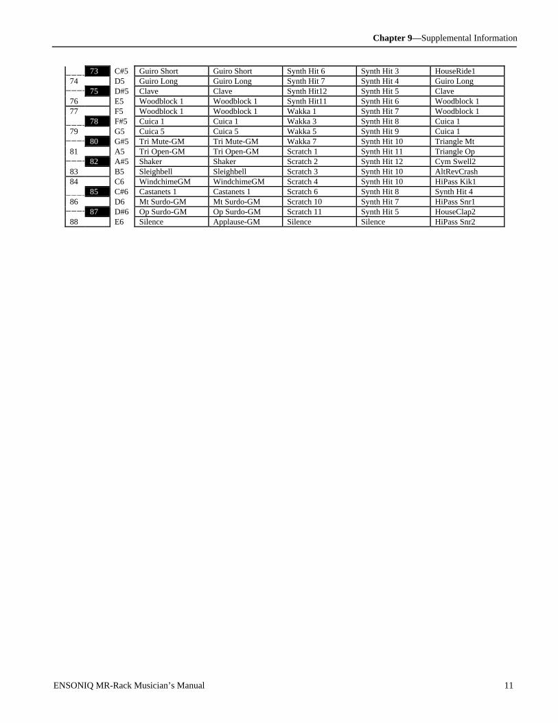
Chapter 9—Supplemental Information
ENSONIQ MR-Rack Musician’s Manual 11
____ 73 C#5 Guiro Short Guiro Short Synth Hit 6 Synth Hit 3 HouseRide174 D5 Guiro Long Guiro Long Synth Hit 7 Synth Hit 4 Guiro Long
____75 D#5 Clave Clave Synth Hit12 Synth Hit 5 Clave
76 E5 Woodblock 1 Woodblock 1 Synth Hit11 Synth Hit 6 Woodblock 177 F5 Woodblock 1 Woodblock 1 Wakka 1 Synth Hit 7 Woodblock 1
____ 78 F#5 Cuica 1 Cuica 1 Wakka 3 Synth Hit 8 Cuica 179 G5 Cuica 5 Cuica 5 Wakka 5 Synth Hit 9 Cuica 1
____80 G#5 Tri Mute-GM Tri Mute-GM Wakka 7 Synth Hit 10 Triangle Mt
81 A5 Tri Open-GM Tri Open-GM Scratch 1 Synth Hit 11 Triangle Op____
82 A#5 Shaker Shaker Scratch 2 Synth Hit 12 Cym Swell283 B5 Sleighbell Sleighbell Scratch 3 Synth Hit 10 AltRevCrash84 C6 WindchimeGM WindchimeGM Scratch 4 Synth Hit 10 HiPass Kik1
____ 85 C#6 Castanets 1 Castanets 1 Scratch 6 Synth Hit 8 Synth Hit 486 D6 Mt Surdo-GM Mt Surdo-GM Scratch 10 Synth Hit 7 HiPass Snr1
____87 D#6 Op Surdo-GM Op Surdo-GM Scratch 11 Synth Hit 5 HouseClap2
88 E6 Silence Applause-GM Silence Silence HiPass Snr2

Chapter 9—Supplemental Information
12 ENSONIQ MR-Rack Musician’s Manual
M R - R ac k M ID I Im ple m e nt at ionThe MR-Rack features an extensive MIDI (Musical Instrument Digital Interface)implementation. For normal applications, you will find all the information you needregarding the MR-Rack’s MIDI functions in this manual. You can also refer to the followingMIDI Implementation Chart for a summary of the MR-Rack MIDI implementation.
If you are writing a computer program to communicate with the MR-Rack via MIDI, orotherwise require a copy of the full MR-Rack System Exclusive Specification, it is availablefree of charge by writing to:
ENSONIQ Corp.MIDI Specification Desk155 Great Valley ParkwayP.O. Box 3035Malvern PA 19355-0735USA
Include in your written request your name and address, and indicate that you would like acopy of the “MR-Rack System Exclusive Specification.” Please allow 2 to 3 weeks for delivery.
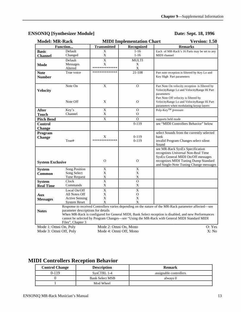
Chapter 9—Supplemental Information
ENSONIQ MR-Rack Musician’s Manual 13
ENSONIQ [Synthesizer Module] Date: Sept. 18, 1996
Model: MR-Rack MIDI Implementation Chart Version: 1.50 Function... Transmitted Recognized Remarks
BasicChannel
DefaultChanged
XX
1-161-16
Each of MR-Rack’s 16 Parts may be set to anyMIDI channel
ModeDefaultMessagesAltered
XX
**************
MULTIXX
NoteNumber
True voice ************** 21-108 Part note reception is filtered by Key Lo andKey High Part parameters
VelocityNote On
Note Off
X
X
O
O
Part Note On velocity reception is filtered byVelocityRange Lo and VelocityRange Hi PartparametersPart Note Off velocity is filtered byVelocityRange Lo and VelocityRange Hi Partparameters when modulating keyup layers
AfterTouch
Key’sChannel
XX
OO
Poly-Key™ pressure
Pitch Bend X O supports held mode
ControlChange
0-119 see “MIDI Controllers Behavior” below
ProgramChange
True#X
**************0-1190-119
select Sounds from the currently selectedbankinvalid Program Changes select silentSound
System Exclusive O O
see MR-Rack SysEx Specificationrecognizes Universal Non-Real TimeSysEx General MIDI On/Off messagesrecognizes MIDI Tuning Dump Standardand Single-Note Tuning Change messages
SystemCommon
Song PositionSong SelectTune Request
XXX
XXX
SystemReal Time
ClockCommands
XX
OX
AuxMessages
Local On/OffAll Notes OffActive SensingSystem Reset
XXXX
XOXX
NotesResponse to received Controllers varies depending on the nature of the MR-Rack parameter affected—seeparameter descriptions for detailsWhen MR-Rack is configured for General MIDI, Bank Select reception is disabled, and new Performancescannot be selected by Program Changes—see “Using the MR-Rack with General MIDI Standard MIDIFiles”, Chapter 3
Mode 1: Omni On, PolyMode 3: Omni Off, Poly
Mode 2: Omni On, MonoMode 4: Omni Off, Mono
O: YesX: No
MIDI Controllers Reception BehaviorControl Change Description Remark
0-119 SysCTRL 1-4 assignable controllers
0 Bank Select MSB always 0
1 Mod Wheel

Chapter 9—Supplemental Information
14 ENSONIQ MR-Rack Musician’s Manual
4 Foot (Pedal)
5 Portamento Time
6 Data Entry MSB for editing of Registered and Non-Registered Parametersonly, after Registered or Non-Registered Parameter MSB
and LSB are received
7 Volume
10 Pan
11 Expression Controller
32 Bank Select LSB
64 Sustain
65 Portamento On/Off
66 Sustenuto
72 Release Time Amp Env Release
73 Attack Time Amp Env Attack
74 Brightness Filter Cutoff
75 Sound Controller 6 Normal LFO Rate
76 Sound Controller 7 Amp Env Decay
91 Effects 1 Depth GM Chorus Depth, described in “Adding Effects to PartSounds,” Chapter 4
93 Effect 2 Depth GM Reverb Depth, described in “Adding Effects to PartSounds,” Chapter 4
98 Non-Reg. Param. Select LSB Part parameter descriptions in Chapter 4 list Partparameters’ Non-Registered parameter LSB values
99 Non-Reg. Param. Select MSB always 0
100 Reg. Param. Select LSB always 0, 1 or 2 only
101 Reg. Param. Select MSB always 0

Chapter 9—Supplemental Information
ENSONIQ MR-Rack Musician’s Manual 15
Li s t of MI DI Con trol l er Nam es This list of MIDI Controller names (as found in the MR-Rack) represents the current state-of-the-art MIDI controller assignments as defined in the MIDI Detailed Specification, version 95.1:
Bank Select #000 - Bank Select Expression#043 - Expression LSB MIDIContrl#086 - UNDEFINED
Mod Wheel #001 - Mod Wheel or Lever FXControl1#044 - Effect Control 1 LSB MIDIContrl#087 - UNDEFINED
Breath #002 - Breath Controller FXControl2#045 - Effect Control 2 LSB MIDIContrl#088 - UNDEFINED
MIDIContrl#003 - UNDEFINED MIDIContrl#046 - UNDEFINED MIDIContrl#089 - UNDEFINED
FootContrl#004 - Foot Controller MIDIContrl#047 - UNDEFINED MIDIContrl#090 - UNDEFINED
Glide Time#005 - Portamento Time GenPurpse1#048 - UNDEFINED FX Depth 1#091 - Effects Depth 1
Data Entry#006 - Data Entry MSB GenPurpse2#049 - General Purpose 1 LSB FX Depth 2#092 - Effects Depth 2
Volume #007 - Volume GenPurpse3#050 - General Purpose 2 LSB FX Depth 3#093 - Effects Depth 3
Balance #008 - Balance GenPurpse4#051 - General Purpose 3 LSB FX Depth 4#094 - Effects Depth 4
MIDIContrl#009 - UNDEFINED MIDIContrl#052 - General Purpose 4 LSB FX Depth 5#095 - Effects Depth 5
Pan #010 - Pan MIDIContrl#053 - UNDEFINED Data Inc #096 - Data Inc
Expression#011 - Expression MIDIContrl#054 - UNDEFINED Data Dec #097 - Data Dec
FX Control1#012 - Effect Control 1 MIDIContrl#055 - UNDEFINED NonRgPmLSB#098 - Non-Reg param Num LSB
FX Control2#013 - Effect Control 2 MIDIContrl#056 - UNDEFINED NonRgPmMSB#099 - Non-Reg param Num MSB
MIDIContrl#014 - UNDEFINED MIDIContrl#057 - UNDEFINED RgParamLSB#100 - Reg param Num LSB
MIDIContrl#015 - UNDEFINED MIDIContrl#058 - UNDEFINED RgParamMSB#101 - Reg param Num MSB
GenPurpse1#016 - General Purpose 1 MIDIContrl#059 - UNDEFINED MIDIContrl#102 - UNDEFINED
GenPurpse2#017 - General Purpose 2 MIDIContrl#060 - UNDEFINED MIDIContrl#103 - UNDEFINED
GenPurpse3#018 - General Purpose 3 MIDIContrl#061 - UNDEFINED MIDIContrl#104 - UNDEFINED
GenPurpse4#019 - General Purpose 4 MIDIContrl#062 - UNDEFINED MIDIContrl#105 - UNDEFINED
MIDIContrl#020 - UNDEFINED MIDIContrl#063 - UNDEFINED MIDIContrl#106 - UNDEFINED
MIDIContrl#021 - UNDEFINED Sustain #064 - Sustain MIDIContrl#107 - UNDEFINED
MIDIContrl#022 - UNDEFINED PortOn/Off#065 - Portamento On/Off MIDIContrl#108 - UNDEFINED
MIDIContrl#023 - UNDEFINED Sostenuto #066 - Sostenuto MIDIContrl#109 - UNDEFINED
MIDIContrl#024 - UNDEFINED Soft Pedal#067 - Soft Pedal MIDIContrl#110 - UNDEFINED
MIDIContrl#025 - UNDEFINED LegatoFtsw#068 - Legato Ftsw MIDIContrl#111 - UNDEFINED
MIDIContrl#026 - UNDEFINED Hold 2 #069 - Hold 2 MIDIContrl#112 - UNDEFINED
MIDIContrl#027 - UNDEFINED PatchSelct#070 - Snd Variation (Patch Select) MIDIContrl#113 - UNDEFINED
MIDIContrl#028 - UNDEFINED Timbre #071 - Harmonic Content (Timbre) MIDIContrl#114 - UNDEFINED
MIDIContrl#029 - UNDEFINED Release #072 - Release MIDIContrl#115 - UNDEFINED
MIDIContrl#030 - UNDEFINED Attack #073 - Attack MIDIContrl#116 - UNDEFINED
MIDIContrl#031 - UNDEFINED Brightness#074 - Brightness MIDIContrl#117 - UNDEFINED
BankSelect#032 - Bank Select LSB SoundCntl6#075 - Sound Controller 6 MIDIContrl#118 - UNDEFINED
Mod Wheel #033 - Mod Wheel LSB SoundCntl7#076 - Sound Controller 7 MIDIContrl#119 - UNDEFINED
Breath #034 - Breath Controller LSB SoundCntl8#077 - Sound Controller 8
MIDIContrl#035 - UNDEFINED SoundCntl9#078 - Sound Controller 9
FootContrl#036 - Foot Controller LSB SoundCtl10#079 - Sound Controller 10
Glide Time#037 - Portamento Time LSB GenPurpse5#080 - General Purpose 5
Data Entry#038 - Data Entry LSB GenPurpse6#081 - General Purpose 6
Volume #039 - Volume LSB GenPurpse7#082 - General Purpose 7
Balance #040 - Balance LSB GenPurpse8#083 - General Purpose 8
MIDIContrl#041 - UNDEFINED Portamento#084 - Portamento Control
Pan #042 - Pan LSB MIDIContrl#085 - UNDEFINED
Note: Controllers #000-031 are the MSBs and #032-063 are the LSBs for controllerswith 14 bit resolution, and their names are displayed identically in the list of values.
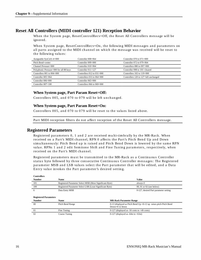
Chapter 9—Supplemental Information
16 ENSONIQ MR-Rack Musician’s Manual
Res et Al l Cont rol l er s ( MI DI con t rol l er 121) Recep t i on Be havi orWhen the System page, ResetControlRecv=Off, the Reset All Controllers message will beignored.
When System page, ResetControlRecv=On, the following MIDI messages and parameters onall parts assigned to the MIDI channel on which the message was received will be reset tothe following values:
Assignable SysCtrl1-4=000 Controller 008=064 Controller 070 to 071=000
Pitch Bend=center Controller 009=000 Controller 072 to 079=064
Channel Pressure=000 Controller 010=064 Controllers 080 to 097=000
Polyphonic Pressure=000 for all 88 keys Controller 011=127 Controller 098 to 101=cleared
Controllers 001 to 004=000 Controllers 012 to 031=000 Controllers 102 to 119=000
Controller 005=064 Controllers 033 to 064=000 Controllers 120 to 127=left unchanged
Controller 006=000 Controller 065=000
Controller 007=100 Controllers 066 to 069=000
When System page, Part Param Reset=Off:Controllers 005, and 070 to 079 will be left unchanged.
When System page, Part Param Reset=On:Controllers 005, and 070 to 079 will be reset to the values listed above.
Part MIDI reception filters do not affect reception of the Reset All Controllers message.
Registered ParametersRegistered parameters 0, 1 and 2 are received multi-timbrally by the MR-Rack. Whenreceived on a Part’s MIDI channel, RPN 0 affects the Part’s Pitch Bend Up and Downsimultaneously: Pitch Bend up is raised and Pitch Bend Down is lowered by the same RPNvalue. RPNs 1 and 2 edit Semitone Shift and Fine Tuning parameters, respectively, whenreceived on the Part’s MIDI channel.
Registered parameters must be transmitted to the MR-Rack as a Continuous Controllerstatus byte followed by three consecutive Continuous Controller messages: The Registeredparameter MSB and LSB values select the Part parameter that will be edited, and a DataEntry value invokes the Part parameter’s desired setting.
Controllers
Number Name Value
101 Registered Parameter Select MSB (Most Significant Byte) always 0
100 Registered Parameter Select LSB (Least Significant Byte) 00, 01 or 02 (see below)
6 Data Entry MSB 0-127, desired Part parameter setting
Registered Parameters
Number Name MR-Rack Parameter Range
00 Pitch Bend Range 0-12 (displayed as Pitch Bend Up =0-12 up raises pitch Pitch BendDown=0-12 down
01 Fine Tuning 0-127 (displayed as -50 cents to +49 cents)
02 Coarse Tuning 0-127 (displayed as -64st to +63st)

Chapter 9—Supplemental Information
ENSONIQ MR-Rack Musician’s Manual 17
Non-Registered ParametersNon-Registered parameters are received multi-timbrally by the MR-Rack, affecting Partparameters when received on the Part’s MIDI channel.
Non-Registered parameters must be transmitted to the MR-Rack as a Continuous Controllerstatus byte followed by three consecutive Continuous Controller messages. The Non-Registered parameter MSB and LSB select the Part parameter, and a Data Entry valueinvokes the Part parameter’s desired setting.
Controllers
Number Name Value
99 Non-Registered Parameter Select MSB (Most Significant Byte) always 0
98 Non-Registered Parameter Select LSB (Least Significant Byte) see Part parameter descriptions in Chapter 4 foreach parameter’s Non-Registered parameter LSBvalue
6 Data Entry MSB 0-127, desired Part parameter setting
R e gist e r e d and Non- R e gist e r e d P ar am e t e r s (R P N /N R P N ) Expression Responds to MIDI controller 011 and NRPN LSB LSB 034.
FX Bus assignment (Insert, Chorus, LightReverb, MediumReverb,WetReverb, Dry)
Responds to MIDI NRPN LSB 033.
Pitch Bend Up Responds to MIDI RPN LSB 000 and NRPN LSB 022.
Pitch Bend Down Responds to MIDI RPN LSB 000 and NRPN LSB 023.
Octave Tuning (-4oct to +4oct) Responds to MIDI NRPN LSB 011.
Semitone Coarse Tuning Responds to MIDI RPN LSB 002.
Fine Tuning Responds to MIDI RPN LSB 001.
Pitch Table Responds to MIDI NRPN LSB 021.
Glide Mode Responds to MIDI controller 065 (see below) and NRPN LSB 031. When avalue of 64 or greater for MIDI controller 065 is received, glide will be enabledfor the part; values below 64 will not disable glide.
Glide Time Responds to MIDI controller 005 and NRPN LSB 032.
Delay Time positive-only Responds to MIDI NRPN LSB 024.
tempo Sync’ed LFO and Noise system tempo time division Responds to MIDI NRPN LSB 025.
Normal LFO Rate Responds to MIDI controller 075 and NRPN LSB 008.
LFO Depth Responds to MIDI NRPN LSB 009.
LFO Delay Time Responds to MIDI NRPN LSB 010.
Amplitude Envelope Attack time Responds to MIDI controller 073 and NRPN LSB 014.
Amplitude Envelope Decay time Responds to MIDI controller 076 and NRPN LSB 015.
Amplitude Envelope Release time Responds to MIDI controller 072 and NRPN LSB 016.
lo-pass & hi-pass Filter Cutoff Responds to MIDI controller 074 and NRPN LSB 012.
Filter Envelope Attack time Responds to MIDI NRPN LSB 017.
Filter Envelope Decay time Responds to MIDI NRPN LSB 018.
Filter Envelope Release time Responds to MIDI NRPN LSB 019.
Amp & Filter Envelope Velocity sensitivity Responds to MIDI NRPN LSB 020.
Key Range Low limit Responds to MIDI NRPN LSB 026.
Key Range High limit Responds to MIDI NRPN LSB 027.
Velocity Range Low limit Responds to MIDI NRPN LSB 028.
Velocity Range High limit Responds to MIDI NRPN LSB 029.
Pressure Mode Responds to MIDI NRPN LSB 030.
Velocity MIDI reception converter Responds to MIDI NRPN LSB 035.
(Part) Mute button Responds to MIDI NRPN LSB 036 (0=normal muted, 1=unmuted, 2=solomuted, 3=solo, 4-127=solo).
For an explanation of how to use RPNs and NRPNs with the MR-Rack, see “Using RPNs andNRPNs to Edit Parameters” at the end of Chapter 4.
Universal Non-Real-Time SysEx General MIDI On/OffThe MR-Rack recognizes the Universal Non-Real-Time SysEx General MIDI On/Offmessages.

Chapter 9—Supplemental Information
18 ENSONIQ MR-Rack Musician’s Manual
When the MR-Rack receives a SysEx General MIDI On message, it responds as if the MR-Rack’s own Hit ENTER for GM! command has been run: the General MIDI Performance isselected, and certain System parameters are reset (see “Using the MR-Rack with GeneralMIDI Standard MIDI Files” in Chapter 3 for details).
The Universal Non-Real-Time SysEx General MIDI On message is comprised of the UniversalNon-Real-Time header, the current SysEx Device ID number of the MR-Rack, sub-ID #1andsub-ID #2 messages, and an End of SysEx message.
Turning General MIDI On Via SysExTransmit Description Notes
F0, 7E Universal Non-Real-Time SysEx header
<Device ID> SysEx Device ID 0-127, determined by the setting of the SysEx DeviceID System parameter (see Chapter 3)
09 sub-ID#1=General MIDI message01 sub-ID#2=General MIDI OnF7 End of SysEx
When the MR-Rack receives a Universal Non-Real-Time SysEx General MIDI Off message, itconcludes General MIDI operation by selecting the →PlaySounds Performance and Part 1.System parameters altered at the start of General MIDI operation are not reset (for a list ofthese parameters, see “Using General MIDI,” Chapter 3).
The Universal Non-Real-Time SysEx General MIDI Off message is comprised of the UniversalNon-Real-Time header, the SysEx Device ID number of the MR-Rack, sub-ID #1and sub-ID#2 messages, and an End of SysEx message.
Turning General MIDI Off Via SysExTransmit Description Notes
F0, 7E Universal Non-Real-Time SysEx header
<Device ID> SysEx Device ID 0-127, determined by the setting of the SysEx DeviceID System parameter (see Chapter 3)
09 sub-ID#1=General MIDI message02 sub-ID#2=General MIDI OffF7 End of SysEx
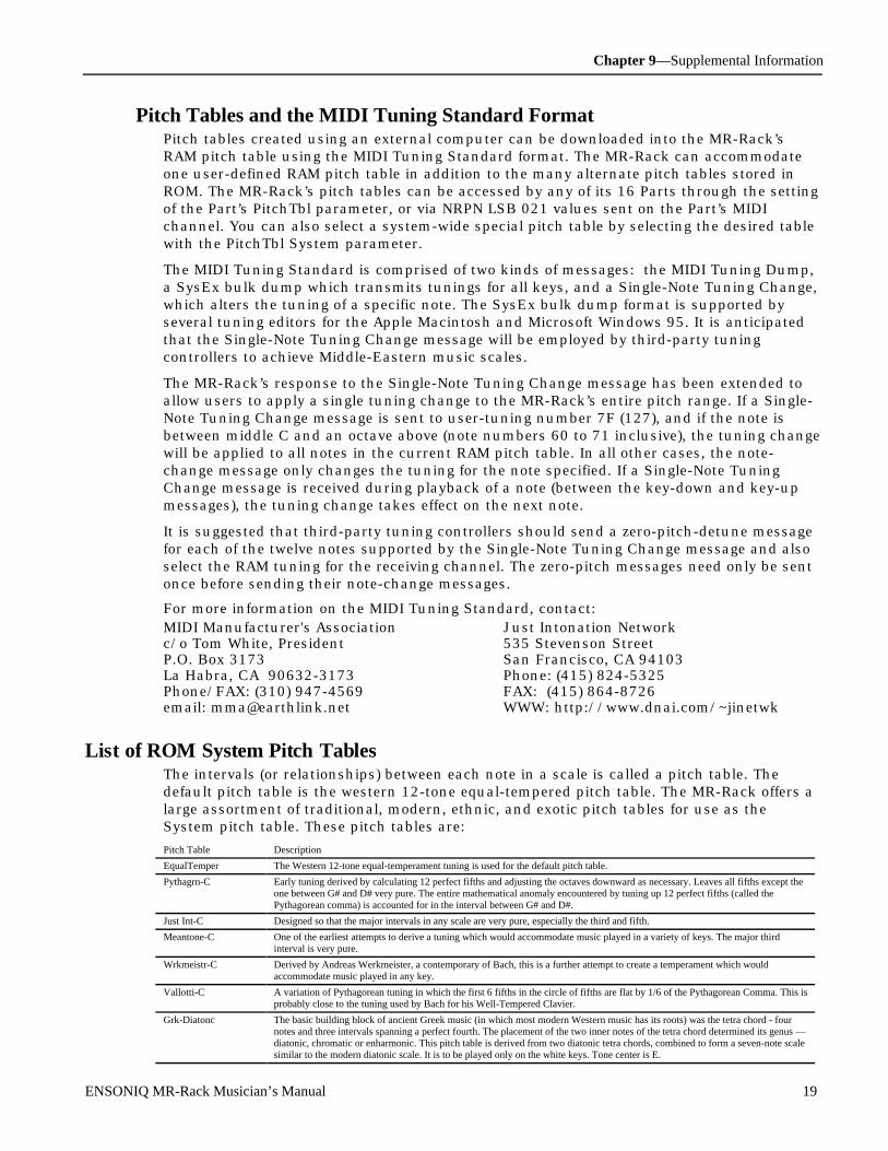
Chapter 9—Supplemental Information
ENSONIQ MR-Rack Musician’s Manual 19
Pitch Tables and the MIDI Tuning Standard FormatPitch tables created using an external computer can be downloaded into the MR-Rack’sRAM pitch table using the MIDI Tuning Standard format. The MR-Rack can accommodateone user-defined RAM pitch table in addition to the many alternate pitch tables stored inROM. The MR-Rack’s pitch tables can be accessed by any of its 16 Parts through the settingof the Part’s PitchTbl parameter, or via NRPN LSB 021 values sent on the Part’s MIDIchannel. You can also select a system-wide special pitch table by selecting the desired tablewith the PitchTbl System parameter.
The MIDI Tuning Standard is comprised of two kinds of messages: the MIDI Tuning Dump,a SysEx bulk dump which transmits tunings for all keys, and a Single-Note Tuning Change,which alters the tuning of a specific note. The SysEx bulk dump format is supported byseveral tuning editors for the Apple Macintosh and Microsoft Windows 95. It is anticipatedthat the Single-Note Tuning Change message will be employed by third-party tuningcontrollers to achieve Middle-Eastern music scales.
The MR-Rack’s response to the Single-Note Tuning Change message has been extended toallow users to apply a single tuning change to the MR-Rack’s entire pitch range. If a Single-Note Tuning Change message is sent to user-tuning number 7F (127), and if the note isbetween middle C and an octave above (note numbers 60 to 71 inclusive), the tuning changewill be applied to all notes in the current RAM pitch table. In all other cases, the note-change message only changes the tuning for the note specified. If a Single-Note TuningChange message is received during playback of a note (between the key-down and key-upmessages), the tuning change takes effect on the next note.
It is suggested that third-party tuning controllers should send a zero-pitch-detune messagefor each of the twelve notes supported by the Single-Note Tuning Change message and alsoselect the RAM tuning for the receiving channel. The zero-pitch messages need only be sentonce before sending their note-change messages.
For more information on the MIDI Tuning Standard, contact:MIDI Manufacturer's Association Just Intonation Networkc/o Tom White, President 535 Stevenson StreetP.O. Box 3173 San Francisco, CA 94103La Habra, CA 90632-3173 Phone: (415) 824-5325Phone/FAX: (310) 947-4569 FAX: (415) 864-8726email: [email protected] WWW: http://www.dnai.com/~jinetwk
Li s t of RO M Syst em Pit ch Tab l esThe intervals (or relationships) between each note in a scale is called a pitch table. Thedefault pitch table is the western 12-tone equal-tempered pitch table. The MR-Rack offers alarge assortment of traditional, modern, ethnic, and exotic pitch tables for use as theSystem pitch table. These pitch tables are:
Pitch Table Description
EqualTemper The Western 12-tone equal-temperament tuning is used for the default pitch table.
Pythagrn-C Early tuning derived by calculating 12 perfect fifths and adjusting the octaves downward as necessary. Leaves all fifths except theone between G# and D# very pure. The entire mathematical anomaly encountered by tuning up 12 perfect fifths (called thePythagorean comma) is accounted for in the interval between G# and D#.
Just Int-C Designed so that the major intervals in any scale are very pure, especially the third and fifth.
Meantone-C One of the earliest attempts to derive a tuning which would accommodate music played in a variety of keys. The major thirdinterval is very pure.
Wrkmeistr-C Derived by Andreas Werkmeister, a contemporary of Bach, this is a further attempt to create a temperament which wouldaccommodate music played in any key.
Vallotti-C A variation of Pythagorean tuning in which the first 6 fifths in the circle of fifths are flat by 1/6 of the Pythagorean Comma. This isprobably close to the tuning used by Bach for his Well-Tempered Clavier.
Grk-Diatonc The basic building block of ancient Greek music (in which most modern Western music has its roots) was the tetra chord - fournotes and three intervals spanning a perfect fourth. The placement of the two inner notes of the tetra chord determined its genus —diatonic, chromatic or enharmonic. This pitch table is derived from two diatonic tetra chords, combined to form a seven-note scalesimilar to the modern diatonic scale. It is to be played only on the white keys. Tone center is E.

Chapter 9—Supplemental Information
20 ENSONIQ MR-Rack Musician’s Manual
Grk-Chromat This pitch table is derived from two chromatic tetra chords (the intervals are, roughly, quarter-tone, half-step, major third),combined to form a seven-note scale. It is meant to be played on the white keys. Tone center is E.
Grk-Enharm This pitch table is derived from two enharmonic tetra chords (the intervals are, more or less, two quarter-tones followed by a majorthird), combined to form a seven-note scale. It is meant to be played on the white keys. Tone center is E.
Turkish-A This is a typical Turkish octave-based scale using only one quarter tone. The second note in the scale is tuned 40 cents flat from theequal-tempered equivalent. In this tuning B is 40 cents flatter from B natural. The scale rises from A.
Arabic-1 The intervals in this table form the basis for much Middle Eastern music. Here the octave is divided into 17 intervals,corresponding to the fret intervals of some stringed instruments used in this area. The scale rises from the base pitch of C4 in aseries of three repeating intervals (in cents) of 90, 90, 24 and so on. From C4 to F5 represents an octave.
Arabic-2 Similar to Arabic 1, except that here the octave is divided into 24 intervals. This makes one pitch octave cover two keyboardoctaves, meaning that the fingering will be the same in any octave. This scale rises from the base pitch of C4 in a series of fourrepeating intervals (in cents) of 24, 66, 24, 90 and so on.
Arabic-3 This is a 12-tone scale using quarter tones (notes tuned sharp or flat by 50 cents from their equal-tempered equivalents) on the C#,E, G# and B keys.
Arabic-4 Another octave-based scale with an Arabic flavor. In this case the “quarter tones” are not perfectly equal, imparting a distinctivecharacter to the notes.
Java-Pelog1 One of the two main scales of the gamelan orchestras of Java and Bali is the seven-tone scale called Pelog. The notes C, D, F , G,and A (which are reproduced on the black keys) are considered primary, with E and B used for grace notes. The octaves arestretched (tuned a little sharp) due to the harmonic content of the instruments in the gamelan. (Note that there are many subtlevariations of these tunings, almost as many as there are gamelan ensembles. The tunings we have included here are to be consideredtypical, not definitive.)
Java-Pelog2 Another version of the seven-tone Pelog scale used in gamelan music. The notes C, D, F , G, and A (which are reproduced on theblack keys) are considered primary, with E and B used for grace notes. The octaves are stretched (tuned a little sharp) due to theharmonic content of the instruments in the gamelan.
Java-Pelog3 A third version of the seven-tone Pelog scale used in gamelan music. The notes C, D, F , G, and A (which are reproduced on theblack keys) are considered primary, with E and B used for grace notes.
Java-Slndro A 15-tone equal tempered tuning from Java. Playing every third note (as in a diminished chord) yields a typical 5-tone scale of thegamelan. Other notes can be used as passing tones.
Java-Combi This is actually two pitch tables in one. The white keys play the seven-tone Pelog scale, same as the table JAVA-PELOG1. Theblack keys play a five-tone scale called Slendro, which is close to a five-tone equi-tempered scale. Both tunings have their octavesstretched (tuned a little sharp) due to the harmonic content of the instruments in the gamelan.
Indian-Raga Indian scale used to play ragas, based on 22 pure intervals called Srutis. This pitch table uses two keyboard octaves to play oneoctave in pitch. The 22 Srutis are mapped to keys in this two-octave range omitting the A#s, which play the same pitch as theadjacent A.
Tibetan This tuning is based on a pentatonic scale from Tibet. Notice that playing the black keys yield a scale similar to the 5-tone Slendrotuning from Indonesia.
Chinese-1 This is a seven-tone scale used widely in China. It is meant to be played on the white keys.
Chinese-2 This is a seven-tone scale based on an ancient Chinese lute tuning. It is meant to be played on the white keys.
Thailand This is a seven-tone equi-tempered scale from Thailand. It is meant to be played on the white keys.
24-Tone-Equ Centered on C4, this scale has an even quarter tone (50 cents) between each keyboard note, and each pitch octave covers 2keyboard octaves. This tuning has been used by many contemporary composers and can be used in some Middle Eastern music.
19-Tone-Equ Centered on C4, this scale divides the octave into 19 equal steps. From C4 to G5 forms an octave. This scale yields very pure thirdsand sixths, but not fifths. Like the 24-tone scale, this has been used by some modern composers.
31-Tone-Equ Centered on C4, this scale divides the octave into 31 equal steps. From C4 to G6 forms an octave. Similar to 19-tone in the purityof its intervals.
53-Tone-Equ This scale divides the octave into 53 equal steps. From C2 to F6 forms an octave. It yields very pure thirds, fourths and fifths.
Harmonic This is a mathematically generated scale based on the relationships of the partials in the harmonics of the fifth octave of the linearharmonic spectrum. It is interesting mostly from a theoretical standpoint.
CarlosAlpha The first of three scales derived mathematically by Wendy Carlos in the search for scales with the maximum purity of primaryintervals, Alpha is based on the division of the octave into 15.385 equal steps (78 cents per key). One pitch “octave” covers 16keys, though because the Carlos scales are asymmetric (not based on whole number divisions of the octave) they do not yield pureoctaves.
Carlos-Beta Wendy Carlos’ Beta scale is based on the division of the octave into 18.809 equal steps 63.8 cents per key. One pitch “octave”covers 19 keys though, being asymmetric, it yields no pure octaves.
CarlosGamma Wendy Carlos’ Gamma scale is based on the division of the octave into 34.188 equal steps (35.1 cents per key). This scale hasessentially perfect major thirds, fourths and fifths. One pitch “octave” covers 35 keys, though, again, being asymmetric it yields nopure octaves.
Partch-43 Harry Partch was a pioneer of micro-tonality in the early 20th century. He developed this 43-tone-per-octave scale of pure intervals,and even designed an entire orchestra of instruments for music using this scale. The tonal center is found on key D2 (the low D onthe 76-note keyboard). This pitch table has been transposed up an octave to bring the notes into a more usable range.
Reverse This pitch table simply reverses the pitch-tracking of the keyboard, putting the highest notes at the bottom of the keyboard and thehighest notes at the top. Lots of fun.
Bagpipe This is the tuning of a traditional Scottish bagpipe.
ShonaMbira1 This is one tuning of the African Mbira, similar to the Kalimba or thumb-piano. Each Mbira player uses his own “tuning” which ishis signature.
ShonaMbira2 Another Mbira tuning.
SuperJust This is a Just Intonation scale created by Wendy Carlos.
88CET 88CET is a scale with a constant interval of 88 cents. It features three different thirds and close approximations to many justintervals. This keyboard mapping omits the G#/Ab key from the system.
Pierce-Bohl This is an octave-repeating stretched scale invented by John Pierce which is derived from a pure twelfth divided into thirteen steps.

Chapter 9—Supplemental Information
ENSONIQ MR-Rack Musician’s Manual 21
WS1 The WS scales have been created for single samples which span the entire keyboard. WS1 maintains 12 tones per octave for twooctaves centered on middle C, then continues to high and low ends of the keyboard with 1/4 of a semitone or 48 tones per octave.
WS2 WS2 maintains 12 tones per octave for three octaves centered on middle C from G to G.
WS3 WS2 maintains 12 tones per octave for four octaves centered on middle C.
Stretch A stretch tuning, in which the middle C is at unity, C1 is detuned flat 40 cents and C8 is detuned sharp 40 cents. The stretch is alinear ramp between these two offsets.
RandomDetun This is a tuning in which each note has been “tweaked” by ±10 cents, giving chords a chorused effect which is different for eachnote.
RAM Selects pitch tables that can be downloaded via MIDI. See earlier in this chapter for more information about RAM pitch tables.
U sing the M R - R ac k Ou tp ut s
A Note About the Main and Aux Output JacksUse standard balanced (TRS) stereo cables or unbalanced (TS) mono cables for theseconnections.
R RL
Mono
L
Mono
Aux
OutputsTRS
Bal/Unbal
As the labels on the Aux Out jacks and Main Out jacks indicate, the MR-Rack employsautomatic switching on each stereo pair of outputs. That is:
• Main Outputs Left and Right are normally stereo outputs. However, if nothing isplugged into the Right Output, the stereo signal will be summed to mono and sent tothe Left Output.
• Similarly, the Aux Outputs Left and Right are normally stereo outputs. However, ifnothing is plugged into the Right Aux Output, the stereo signal will be summed to monoand sent to the Left Aux Output.
Note: If there is nothing connected to the Left Aux Out jack, any signal sent to theAux Outputs will be summed into the Main Outputs.
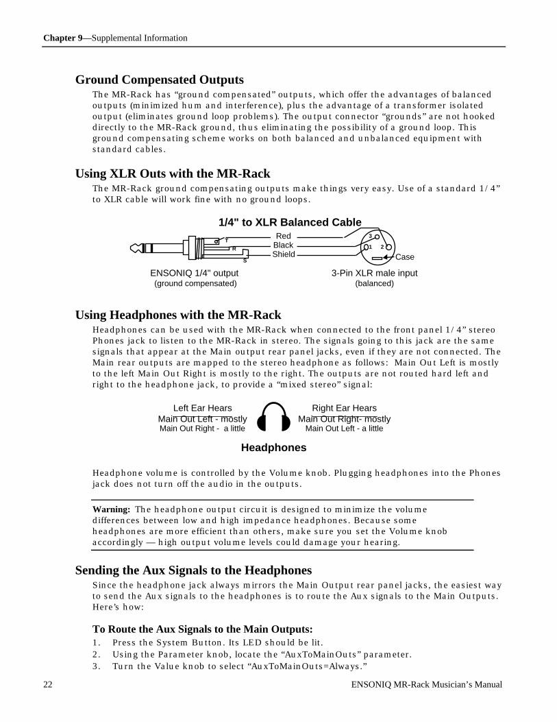
Chapter 9—Supplemental Information
22 ENSONIQ MR-Rack Musician’s Manual
Ground Compensated OutputsThe MR-Rack has “ground compensated” outputs, which offer the advantages of balancedoutputs (minimized hum and interference), plus the advantage of a transformer isolatedoutput (eliminates ground loop problems). The output connector “grounds” are not hookeddirectly to the MR-Rack ground, thus eliminating the possibility of a ground loop. Thisground compensating scheme works on both balanced and unbalanced equipment withstandard cables.
Using XLR Outs with the MR-RackThe MR-Rack ground compensating outputs make things very easy. Use of a standard 1/4”to XLR cable will work fine with no ground loops.
1
3
2R
T
1/4" to XLR Balanced Cable
3-Pin XLR male input(balanced)
S
BlackRed
Shield
ENSONIQ 1/4" output (ground compensated)
Case
Using Headphones with the MR-RackHeadphones can be used with the MR-Rack when connected to the front panel 1/4” stereoPhones jack to listen to the MR-Rack in stereo. The signals going to this jack are the samesignals that appear at the Main output rear panel jacks, even if they are not connected. TheMain rear outputs are mapped to the stereo headphone as follows: Main Out Left is mostlyto the left Main Out Right is mostly to the right. The outputs are not routed hard left andright to the headphone jack, to provide a “mixed stereo” signal:
Headphones
Left Ear HearsMain Out Left - mostlyMain Out Right - a little
Right Ear HearsMain Out Right- mostly
Main Out Left - a little
Headphone volume is controlled by the Volume knob. Plugging headphones into the Phonesjack does not turn off the audio in the outputs.
Warning: The headphone output circuit is designed to minimize the volumedifferences between low and high impedance headphones. Because someheadphones are more efficient than others, make sure you set the Volume knobaccordingly — high output volume levels could damage your hearing.
Sending the Aux Signals to the HeadphonesSince the headphone jack always mirrors the Main Output rear panel jacks, the easiest wayto send the Aux signals to the headphones is to route the Aux signals to the Main Outputs.Here’s how:
To Route the Aux Signals to the Main Outputs:1. Press the System Button. Its LED should be lit.2. Using the Parameter knob, locate the “AuxToMainOuts” parameter.3. Turn the Value knob to select “AuxToMainOuts=Always.”

Chapter 9—Supplemental Information
ENSONIQ MR-Rack Musician’s Manual 23
Now whatever was routed to the Aux jacks is now being sent to the Main Outputs, andtherefore, can be heard in the Headphones.
Note: Remember to reset the System “AuxToMainOuts” parameter if you do not wantto send the Aux signals to the Main Outputs.
Tr ouble shoot ing the M R - R ac kThe successful operation of a MIDI rig depends on proper settings for all of the gearinvolved. However, even when your other equipment is correctly configured, there may betimes when things don’t go quite as you planned.
If the MR-Rack Doesn’t Play
Symptom:You’re playing your controller or running your sequencer, but the MR-Rack is silent.
What’s Going On:There are a few possibilities. Follow the steps below until the problem is solved.
Remedy:1. Make sure that your controller’s or sequencer’s MIDI Out is connected to the MR-Rack’s
MIDI In. If you’re using a MIDI patchbay or going through a computer, consult thedocumentation for those devices to make sure you connections are correctly made.(Chapter 2—Connections describes how to use the MR-Rack in a number of commonMIDI set-ups.)
2. Settlinger’s Law (who was that guy, anyway?) demands that you confirm that all thedevices involved are powered up.
3. Ascertain the MIDI channel or channels that your controller or sequencer istransmitting on.
4. Press the MR-Rack’s Sound button and use the MR-Rack’s up and down Select Partbuttons to make sure that the Part or Parts you want to use are set to the MIDIchannel(s) your controller or sequencer is set to.
5. If the Part MIDI channel(s) doesn’t agree with your controller’s or sequencer’s, you’llhave to change either the MR-Rack’s or your controller’s or sequencer’s setting(s). Tochange the MR-Rack’s, press the Params button once or twice to display each relevantPart’s MIDI Chan parameter, and use the Value knob to reset the Part’s channel.
6. If a Part is set to Stak, press the System button, and use the Parameter knob to locatethe Stak MIDI Channel parameter and learn which MIDI channel Stak is set to. If itneeds to be changed, use the Value knob to change it. (Staks are described fully in“Using Staks” in Chapter 4—Parts)
7. If you’re still having trouble, call ENSONIQ Customer Service at (610) 647-3930.
If You’re Hearing Sounds You Don’t Expect to Hear
Symptom:You’d like to listen to individual Sounds, but when you select one, you seem to be hearingadditional Sounds.
What’s Going On:The MR-Rack’s Parts can be set so that they share MIDI channels. You’re in a Performancewhere this is the case.
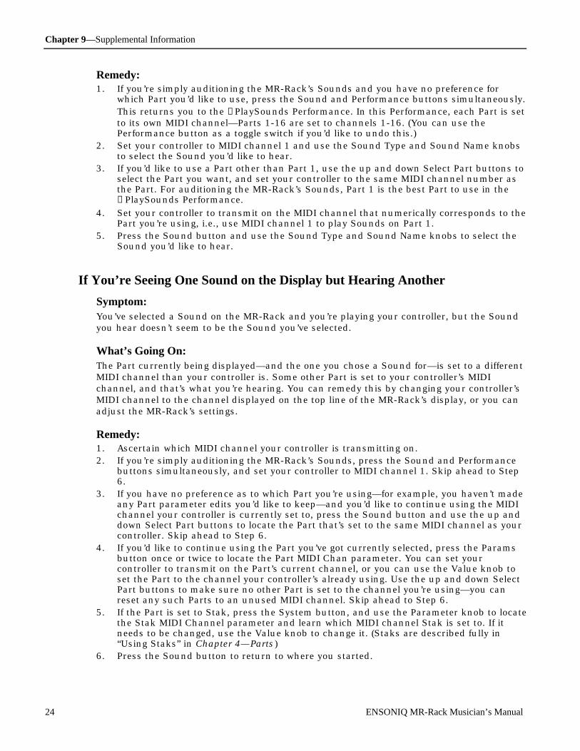
Chapter 9—Supplemental Information
24 ENSONIQ MR-Rack Musician’s Manual
Remedy:1. If you’re simply auditioning the MR-Rack’s Sounds and you have no preference for
which Part you’d like to use, press the Sound and Performance buttons simultaneously.This returns you to the →PlaySounds Performance. In this Performance, each Part is setto its own MIDI channel—Parts 1-16 are set to channels 1-16. (You can use thePerformance button as a toggle switch if you’d like to undo this.)
2. Set your controller to MIDI channel 1 and use the Sound Type and Sound Name knobsto select the Sound you’d like to hear.
3. If you’d like to use a Part other than Part 1, use the up and down Select Part buttons toselect the Part you want, and set your controller to the same MIDI channel number asthe Part. For auditioning the MR-Rack’s Sounds, Part 1 is the best Part to use in the→PlaySounds Performance.
4. Set your controller to transmit on the MIDI channel that numerically corresponds to thePart you’re using, i.e., use MIDI channel 1 to play Sounds on Part 1.
5. Press the Sound button and use the Sound Type and Sound Name knobs to select theSound you’d like to hear.
If You’re Seeing One Sound on the Display but Hearing Another
Symptom:You’ve selected a Sound on the MR-Rack and you’re playing your controller, but the Soundyou hear doesn’t seem to be the Sound you’ve selected.
What’s Going On:The Part currently being displayed—and the one you chose a Sound for—is set to a differentMIDI channel than your controller is. Some other Part is set to your controller’s MIDIchannel, and that’s what you’re hearing. You can remedy this by changing your controller’sMIDI channel to the channel displayed on the top line of the MR-Rack’s display, or you canadjust the MR-Rack’s settings.
Remedy:1. Ascertain which MIDI channel your controller is transmitting on.2. If you’re simply auditioning the MR-Rack’s Sounds, press the Sound and Performance
buttons simultaneously, and set your controller to MIDI channel 1. Skip ahead to Step6.
3. If you have no preference as to which Part you’re using—for example, you haven’t madeany Part parameter edits you’d like to keep—and you’d like to continue using the MIDIchannel your controller is currently set to, press the Sound button and use the up anddown Select Part buttons to locate the Part that’s set to the same MIDI channel as yourcontroller. Skip ahead to Step 6.
4. If you’d like to continue using the Part you’ve got currently selected, press the Paramsbutton once or twice to locate the Part MIDI Chan parameter. You can set yourcontroller to transmit on the Part’s current channel, or you can use the Value knob toset the Part to the channel your controller’s already using. Use the up and down SelectPart buttons to make sure no other Part is set to the channel you’re using—you canreset any such Parts to an unused MIDI channel. Skip ahead to Step 6.
5. If the Part is set to Stak, press the System button, and use the Parameter knob to locatethe Stak MIDI Channel parameter and learn which MIDI channel Stak is set to. If itneeds to be changed, use the Value knob to change it. (Staks are described fully in“Using Staks” in Chapter 4—Parts)
6. Press the Sound button to return to where you started.

Chapter 9—Supplemental Information
ENSONIQ MR-Rack Musician’s Manual 25
If You’re Selecting New Sounds But What You Hear Remains the Same
Symptom:You’re picking new Sounds from the front panel, but the MR-Rack keeps playing the sameone.
What’s Going On:The Part currently being displayed—and the one you’re choosing Sounds for—is set to adifferent MIDI channel than your controller is. Some other Part is set to your controller’sMIDI channel, and that’s what you’re hearing. You can remedy this by changing yourcontroller’s MIDI channel to the channel displayed on the top line of the MR-Rack’s display,or you can adjust the MR-Rack’s settings.
Remedy:1. Ascertain which MIDI channel your controller is transmitting on.2. If you’re simply auditioning the MR-Rack’s Sounds, press the Sound and Performance
buttons simultaneously, and set your controller to MIDI channel 1. Skip ahead to Step6.
3. If you have no preference as to which Part you’re using—for example, you haven’t madeany Part parameter edits you’d like to keep—and you’d like to continue using the MIDIchannel your controller is currently set to, press the Sound button and use the up anddown Select Part buttons to locate the Part that’s set to the same MIDI channel as yourcontroller. Skip ahead to Step 6.
4. If you’d like to continue using the Part you’ve got currently selected, press the Paramsbutton once or twice to locate the Part MIDI Chan parameter. You can set yourcontroller to transmit on the Part’s current channel, or you can use the Value knob toset the Part to the channel your controller’s already using. Use the up and down SelectPart buttons to make sure no other Part is set to the channel you’re using—you canreset any such Parts to an unused MIDI channel. Skip ahead to Step 6.
5. If the Part is set to Stak, press the System button, and use the Parameter knob to locatethe Stak MIDI Channel parameter and learn which MIDI channel Stak is set to. If itneeds to be changed, use the Value knob to change it. (Staks are described fully in“Using Staks” in Chapter 4—Parts)
6. Press the Sound button to return to where you started.
If Sounds Are Behaving Unexpectedly
Symptom:Any odd behavior could qualify: Sounds play only in certain key ranges, they respond oddlyto controllers or not at all, they seem to be going through unexpected Effect. In general, ifthings are behaving strangely, this one’s for you.
What’s Going On:The MR-Rack is an extremely flexible device. Parts—and therefore their Sounds—and Effectscan be set to do many interesting things. You’re in a Performance where the Part or Effectsettings are producing the unexpected behavior you’re experiencing.
Remedy:1. If you’re simply trying to audition the MR-Rack’s Sounds or haven’t made any edits you
want to keep, press the Sound and Performance buttons simultaneously. (If you don’twant to lose edits you’ve made, skip to Step 5.)This returns you to the →PlaySounds Performance. In this Performance, each Part is setto its own MIDI channel—Parts 1-16 are set to channels 1-16.
Chapter 9—Supplemental Information
26 ENSONIQ MR-Rack Musician’s Manual
2. Press the Sound button.3. Set your controller to transmit on MIDI channel 1 to play Sounds on Part 1.4. Use the Sound Type and Sound Name knobs to select the Sound you’d like to hear.5. If you’ve been creating a set-up you’d like to preserve, use the up and down Select Part
buttons to select the Part (or Parts) behaving oddly.6. Press the Params button and use the Parameter knob to view each of the Part
parameters—be on the lookout for settings that could be causing your problem. Payspecial attention to the Part FX Bus parameter if you suspect that Effects mightsomehow be involved in the problem.
7. Use the Value knob to change suspicious parameter settings. Try each change out tosee if you’ve isolated the culprit.
8. If you’re still experiencing odd behavior, press the Effects button.9. If checking the Part parameters revealed that the problem Part(s) is routed to the Insert
Effect, use the Parameter knob to select “Press ENTER to Edit Insert Effect.” PressEnter.
10. Use the Parameter knob to view each of the Insert Effect parameters—watch out forsettings that could be causing your problem (see Chapter 8 for an explanation of theInsert Effect parameters). Use the Value knob to change suspicious settings. Try eachchange out.
If the Sounds You’re Hearing Sound Unexpectedly Strange
Symptom:You’re listening to one of the MR-Rack’s Sounds, and it doesn’t Sound like its name, orsounds odd. When you choose new Sounds, they all sound similarly peculiar.
What’s Going On:You’re listening to the Sounds through an inappropriate Insert Effect.
Remedy:1. If all you want to do is audition the MR-Rack’s Sounds, press the Sound and
Performance buttons simultaneously. This sets you up to listen to Sounds on Part 1,which has been designated as the Insert Control Part—when you select a new Sound onan Insert Control Part, the MR-Rack installs the Sound’s own Insert Effect, if it has one,or routes the Part to the Global Chorus or Global Reverb. Use the Sound Type andSound Name knobs to select Sounds and play them via MIDI channel 1.
2. If you’d like to continue using the Part you’re currently working with, you can designateit as the Insert Control Part—when you select new Sounds, the MR-Rack will install theproper Effect for the Sound. Press Effects, use the Parameter knob to locate the InsertControl Part parameter and use the Value knob to set the parameter to the Part you’reusing.
3. If you’d rather hear the Sounds you’re selecting through the Global Chorus, GlobalReverb or without Effects (Dry), press the Params button once or twice to locate the PartFX Bus parameter, and use the Value knob to send the Part, and its Sounds, whereyou’d like them to go.
4. If the Part you’re using is the Insert Control Part, whenever you choose a new Sound,the MR-Rack will automatically set the Part to the routing programmed into the Sound.If this is occurs and is undesirable, press Effects, use the Parameter knob to locate theInsert Control Part parameter and use the Value knob to set the parameter to a Partyou’re not using, or to Off.
If You’re Hearing Music You Don’t Expect to Hear
Symptom:

Chapter 9—Supplemental Information
ENSONIQ MR-Rack Musician’s Manual 27
The MR-Rack is playing melodies, chords or rhythms it’s not supposed to be playing.
What’s Going On:The MR-Rack, being a multi-timbral device, can receive on all 16 MIDI channelssimultaneously, and its Parts can be set to any MIDI channel. It may be that one or moreParts are set to the same channel(s) you’re using for other instruments in your MIDI set-up,and that the MR-Rack is therefore responding to MIDI information intended for those otherinstruments.
Remedy:1. Press the Sound button.2. Use the up and down Select Part buttons to see what Sound is on each Part in order to
decide which Part(s) you want to use. The top line of the display will also tell you theMIDI channel each Part is set to.
3. If a Part you want to use is set to the wrong MIDI channel, press the Params buttononce or twice to display the Part’s MIDI Chan parameter, and use the Value knob toreset the Part’s channel. Skip ahead to Step 5.
4. If the Part is set to Stak, press the System button, and use the Parameter knob to locatethe Stak MIDI Channel parameter and learn which MIDI channel Stak is set to. If itneeds to be changed, use the Value knob to change it.
5. Press Sound again.6. Using the Select Part buttons, select a Part you don’t intend to use.7. If the word “mute” doesn’t already appear in the display, press the Mute button once.
“Mute” will appear and the Mute button’s red LED will light.8. Repeat Steps 6 and 7 for each Part that you won’t be using. (To un-mute a Part, press
Mute again.)9. If you’re using an Insert Effect, press the Effect button and turn the Parameter knob to
locate the Insert Control Part parameter. Make sure that the Insert Control Part is anunmuted Part, or that it’s set to Off (Chapter 5 explains the Insert Control Part).
10. Now that the MR-Rack is working as you want it to, it would be good idea to save thisset-up as a new Performance. See “Saving the Current Performance” in Chapter 6 forinstructions.
Sounds That You Expect to Hear Are Unexpectedly Silent
Symptom:You’re playing your controller or sequencer and Parts (and their Sounds) which previouslyplayed are no longer there.
What’s Going On:There are two main possibilities: either the missing Part(s) has been inadvertently set to anincorrect MIDI channel, or it’s been muted.
Remedy:1. Press the Sound button.2. Use the up and down Select Part buttons to examine each Part. Verify that each Part is
set to the MIDI channel that you intended, and is not muted (as evidenced by the word“mute” in the display and the Mute button’s red LED switching on when you select aPart).
3. If a Part is set to the wrong MIDI channel, press the Params button once or twice tolocate the Part MIDI Chan parameter, and use the Value knob to set it correctly.
4. If a Part is improperly muted, press the Mute button to unmute it.5. Once the MR-Rack is working as you want it to, it would be good idea to save this set-

Chapter 9—Supplemental Information
28 ENSONIQ MR-Rack Musician’s Manual
up as a Performance. See “Saving the Current Performance” in Chapter 6 forinstructions.
The MR-Rack is Not Responding to Program Changes or Bank Selects
Symptom:You’re sending MIDI program changes or Bank Select messages to the MR-Rack, but it’s notresponding.
What’s Going On:There are two main possibilities: you’re in a Performance where Program Changes or BankSelects have been disabled, or reception to these messages has been turned off on a system-wide level.
Remedy:1. If all you want to do is audition the MR-Rack’s Sounds, press the Sound and
Performance buttons simultaneously. This places you in the →PlaySounds Performance,where Program Changes and Bank Select reception has been enabled for all Parts. Ifthis doesn’t solve your problem, skip to Step 3.
2. If you’d like to continue using the Part you’re currently working with, press the Paramsbutton and use the Parameter knob to locate the ProgramChngeRecv and Bank SelectRecv parameters. Set the relevant parameter to On.
3. Press the System button and use the Parameter knob to locate the Bank&ProgChgRecvparameter. This parameter must be set to On in order for the MR-Rack to respond toProgram Change and Bank Select messages.
You’re Trying to Modulate a Sound Via MIDI, But Nothing’s Happening
Symptom:You’re trying to modulate a Sound with a pitch bend wheel, mod wheel or other MIDIcontrol, and the Sound isn’t responding.
What’s Going On:There are two possibilities: either the Part that the Sound is using is set to ignore themodulator, or the MR-Rack doesn’t respond to the modulator without being specificallyinstructed to do so. If you’re creating your own MR-Rack Sounds using a computer editor,you can program them to respond to any MIDI controls you’d like.
Remedy:1. The MR-Rack provides reception filters for MIDI Volume, Expression, Pan, Pitch Bend,
Velocity, Channel Pressure, Key (Polyphonic) Pressure, Data Entry, Mod Wheel, FootPedal and Sustain/Sostenuto. If you’re using one of these modulators, press the Soundbutton, and use the up and down Select Part buttons to select the Part using the Soundthat’s not responding as you’d like it to.
2. Press Params and use the Parameter knob to locate the reception filter for themodulator you’re using. Most of these parameters are displayed as: [Modulator name]Recv=. Use the Value knob to set the appropriate reception filter to On. Velocity isenabled or disabled for each Part with the VelocityRange Lo and Hi, and Velocity Modeparameters—try setting Lo to 0 and Hi to 127, and Velocity Mode to Normal. Use thePressureMode parameter to enable or disable Part response to Channel or Key Pressureresponse—if you’re not sure which kind of Pressure you’re using, set it to Auto.
3. If you’re using a modulator other than those listed above, press the System button anduse the Parameter knob to locate the CTRL1, CTRL2, CTRL3 and CTRL4 parameters. If

Chapter 9—Supplemental Information
ENSONIQ MR-Rack Musician’s Manual 29
one of these is not already set to the modulator you want to use, choose a CTRL anduse the Value knob to dial in your modulator, either by name or MIDI control number.(If you’re dialing in a modulator by name, you may find the name appearing twice in thelist use its lowest numbered, MSB, version.)
4. Press the Sound button, and use the up and down Select Part buttons to select the Partusing the non-responding Sound.
5. Press Params and use the Parameter knob to locate the reception filter for the CTRLyou’ve chosen to use.
6. Use the Value knob to set the selected CTRL reception filter to On.
You’re Trying to Modulate an Effect Via MIDI, But Nothing’s Happening
Symptom:You’re trying to modulate an Effect with a pitch bend wheel, mod wheel or other MIDIcontrol, and the Sound isn’t responding.
What’s Going On:There are four main possibilities. The Part that’s receiving your real-time MIDI control isn’tthe Insert Control Part, and therefore has no control over the Insert Effect. The InsertControl Part may be set to ignore your modulator. The MR-Rack may need to be specificallyinstructed to respond to the your modulator. Or the current Insert Effect has not yet beenprogrammed to respond to real-time control. Try the steps below until your problem issolved.
It may also be that after correctly setting up your real-time modulation parameters, youchanged the Insert Effect itself—when you pick a new Insert Effect, these parameters revertto their default values, and must be reset.
Remedy:1. Press the Effects button and use the Parameter knob to locate the Insert Control Part
parameter. Select the Part you want to use to control the Insert Effect. Press Paramsonce or twice to locate the Part MIDI Chan parameter. Use the up and down Select Partbuttons to locate the designated Insert Control Part. Reset your controller to send itsreal-time control messages on the MIDI channel displayed, or use the value knob to setthe Insert Control Part to the MIDI channel your controller’s set to.
2. The MR-Rack provides reception filters for MIDI Volume, Expression, Pan, Pitch Bend,Velocity, Channel Pressure, Key (Polyphonic) Pressure, Data Entry, Mod Wheel, FootPedal and Sustain/Sostenuto. If you’re using one of these modulators, press the Soundbutton, and use the up and down Select Part buttons to select the Part designated asthe Insert Control Part.
3. Press Params and use the Parameter knob to locate the reception filter for themodulator you’re using. Most of these parameters are displayed as: [Modulator name]Recv=. Use the Value knob to set the appropriate reception filter to On. Velocity isenabled or disabled for each Part with the VelocityRange Lo and Hi, and Velocity Modeparameters—try setting Lo to 0 and Hi to 127, and Velocity Mode to Normal. Use thePressureMode parameter to enable or disable Part response to Channel or Key Pressureresponse—if you’re not sure which kind of Pressure you’re using, set it to Auto. Skip toStep 7.
4. If you’re using a modulator other than those listed above, press the System button anduse the Parameter knob to locate the CTRL1, CTRL2, CTRL3 and CTRL4 parameters. Ifone of these is not already set to the modulator you want to use, choose one of themand use the Value knob to dial in your modulator, either by name or MIDI controlnumber. (If you’re dialing in a modulator by name, you may find the name appearingtwice in the list use its lowest numbered, MSB, version.) You won’t want to set multipleCTRLs to the same controller if you do, the MR-Rack will only use the lowest-numberedCTRL set to the controller.
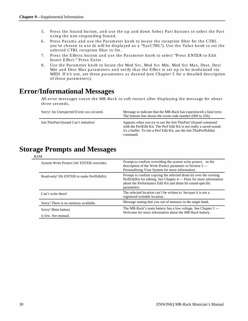
Chapter 9—Supplemental Information
30 ENSONIQ MR-Rack Musician’s Manual
5. Press the Sound button, and use the up and down Select Part buttons to select the Partusing the non-responding Sound.
6. Press Params and use the Parameter knob to locate the reception filter for the CTRLyou’ve chosen to use (it will be displayed as a “SysCTRL”). Use the Value knob to set theselected CTRL reception filter to On.
7. Press the Effects button and use the Parameter knob to select “Press ENTER to EditInsert Effect.” Press Enter.
8. Use the Parameter knob to locate the Mod Src, Mod Src Min, Mod Src Max, Dest, DestMin and Dest Max parameters and verify that the Effect is set up to be modulated viaMIDI. If it’s not, set these parameters as desired (see Chapter 5 for a detailed descriptionof these parameters).
Er r or /Inf or m at ional M e ssage sAll error messages cause the MR-Rack to soft restart after displaying the message for aboutthree seconds.
Sorry! An Unexpected Event xxx occured. Message to indicate that the MR-Rack has experienced a fatal error.The bottom line shows the event code number (000 to 256).
Init:ThisPart'sSound Can’t initialize! Appears when you try to use the Init:ThisPart’sSound commandwith the PerfEdit Kit. The Perf Edit Kit is not really a saved sound,it's a buffer. To init a Perf Edit Kit, use the Init:ThisPerfEditkitcommand.
St or age P r om pt s and M e ssage sRAM
System Write Protect On! ENTER overrides. Prompt to confirm overriding the system write protect. ee thedescription of the Write Protect parameter in Section 3 —Personalizing Your System for more information.
Read-only! Hit ENTER to make PerfEditKit. Prompt to confirm copying the selected drum kit over the existingPerfEditKit for editing. See Chapter 4 — Parts for more informationabout the Performance Edit Kit and drum kit sound-specificparameters.
Can’t write there! The selected location can’t be written to because it is not aregistered writable location.
Sorry! There is no memory available. Message stating that you out of memory in the target bank.
Sorry! Main battery
is low. See manual.
The MR-Rack’s main battery has a low voltage. See Chapter 1 —Welcome for more information about the MR-Rack battery.

Chapter 9—Supplemental Information
ENSONIQ MR-Rack Musician’s Manual 31
Card
* Unformatted card * The format of the card inserted was not recognized.
PCMCIA Card Inserted Registering... This message appears while the MR-Rack adds the contents of acard to its directory index after a card is inserted.
PCMCIA Card Removed Unregistering... This message appears while the MR-Rack removes the contents of acard from its directory index after a card is removed.
Card Write Protect! This message is to remind you that you can’t write to ROM cardsand write-protected cards.
No Card Inserted! This message is to remind you that no card is present, and hence thecopy function selected cannot be executed.
Sorry! Save to card failed. Check media The attempted save to the card has failed have the card inspectedfor electrical anomalies.
Sorry! Too big. Hit ENTER to copy ###%. Message to inform you that the ROM card sound bank that you wantto copy to RAM won’t all fit, and a prompt to perform a partial copy(a percent).
* Card battery low * The MR-Rack’s card battery has a low voltage.
MIDI SysEx
Dump: <dump type> Sending... Message to inform that the MR-Rack is transmitting MIDI SysEx.
RCV: <message type> Receiving <msg type> Message to inform that the MR-Rack is receiving MIDI SysEx.
RCV: <message type> Successful! Message to inform that MIDI SysEx reception is complete.
Bad location This is displayed when trying to send a sound into a ROM location.
Wrong checksum This appears if the checksum is incorrect.
Failed! May be hosed Message to inform you that the Sound or Performance bank may becorrupted.
Sorry! No memory for sound sent from MIDI Message to inform that the MR-Rack does not have sufficientmemory to store the single sound SysEx message that was sent to it.

Chapter 9—Supplemental Information
32 ENSONIQ MR-Rack Musician’s Manual
The Unisyn M R - R ac k Sof t w ar eThe Unisyn MR-Rack software provides a way to create and edit MR-Rack Sounds andPerformances with your computer. Before you begin, you must first connect your MR-Rackto a Macintosh or IBM-compatible computer. For more information about setting up the MR-Rack with a computer, see the MR-Rack Musician’s Manual, Section 2—Connections, as wellas Unisyn’s own documentation. Consult your Unisyn documentation to familiarize yourselfwith the way that Unisyn operates.
The following sections provide information specific to using the three Unisyn editingmodules for the MR-Rack: the Sound Editor, the DrumKit Editor and the Perform(Performance) Editor. It is assumed that you’ve already powered up the MR-Rack and yourcomputer, and have successfully launched and configured the Unisyn software.
U sing the U nisyn Sound Edit or The Unisyn MR-Rack Sound Editor module allows you to program new MR-Rack Sounds, orto customize pre-existing Sounds. The Sound Editor works with standard—that is, non-Drum Kit—MR-Rack Sounds. (Read “Using the Unisyn DrumKit Editor” to learn how tocreate and edit Drum Kit Sounds with Unisyn). For a detailed description of standardSounds, see “Sound Editor Overview,” below.
There are three general areas of new knowledge required for using the Unisyn MR-RackSound Editor:
• the methods for moving standard Sounds back and forth between your computer andthe MR-Rack
• how to move Sound elements within and between Sounds• the Sound-creation and editing capabilities of the Sound Editor itself
Getting Pre-Existing Standard Sounds From the MR-Rack Into UnisynWhen you’d like to use Unisyn to edit a pre-existing MR-Rack Sound, the first step is tomove the Sound from the MR-Rack into Unisyn.
To Move a Standard Sound From the MR-Rack Into Unisyn1. Locate the Sound you want to edit on the MR-Rack and note its MIDI Bank Select and
Program Change numbers.
MIDI Bank Select number MIDI Program Change number
m m
pt01 §01 ROM004:080DEMO-SND: Evolution
2. After launching Unisyn, double-click on the Sound Editor module in Unisyn’s Moduleswindow, or select Sound from the sub-menu in the Modules pull-down menu.This opens Unisyn’s Sound Editor module—you’ll probably want to expand it to its fullview.
3. Set Unisyn’s Use MIDI Chan parameter to the MIDI channel you’d like to use for sendingprogram changes to the MR-Rack and for playing its Sounds from your computer.
4. Set Unisyn’s Sound Bank # to the MR-Rack Sound’s displayed MIDI Bank Selectnumber.
5. Set Unisyn’s Sound Patch # to the MR-Rack Sound’s displayed MIDI Program Changenumber.
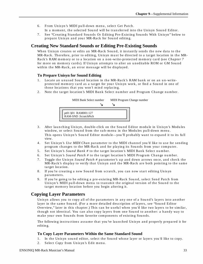
Chapter 9—Supplemental Information
ENSONIQ MR-Rack Musician’s Manual 33
6. From Unisyn’s MIDI pull-down menu, select Get Patch.In a moment, the selected Sound will be transferred into the Unisyn Sound Editor.
7. See “Creating Standard Sounds Or Editing Pre-Existing Sounds With Unisyn” below toprepare Unisyn and your MR-Rack for Sound editing.
Creating New Standard Sounds or Editing Pre-Existing SoundsWhen Unisyn creates or edits an MR-Rack Sound, it instantly sends the new data to theMR-Rack. Therefore, prior to editing, Unisyn must be directed to a target location in the MR-Rack’s RAM memory or to a location on a non-write-protected memory card (see Chapter 7for more on memory cards). If Unisyn attempts to alter an uneditable ROM or GM Soundwithin the MR-Rack, an error message will be displayed.
To Prepare Unisyn for Sound Editing1. Locate an unused Sound location in the MR-Rack’s RAM bank or on an un-write-
protected memory card as a target for your Unisyn work, or find a Sound in one ofthose locations that you won’t mind replacing.
2. Note the target location’s MIDI Bank Select number and Program Change number.
MIDI Bank Select number MIDI Program Change number
m m
pt01 §01 RAM001:127RAM-SND :ScratchPtch
3. After launching Unisyn, double-click on the Sound Editor module in Unisyn’s Moduleswindow, or select Sound from the sub-menu in the Modules pull-down menu.This opens Unisyn’s Sound Editor module—you’ll probably want to expand it to its fullview.
4. Set Unisyn’s Use MIDI Chan parameter to the MIDI channel you’d like to use for sendingprogram changes to the MR-Rack and for playing its Sounds from your computer.
5. Set Unisyn’s Sound Bank # to the target location’s MIDI Bank Select number.6. Set Unisyn’s Sound Patch # to the target location’s MIDI Program Change number.7. Toggle the Unisyn Sound Patch # parameter’s up and down arrows once, and check the
MR-Rack’s display to verify that Unisyn and the MR-Rack are both pointing to the sametarget location.
8. If you’re creating a new Sound from scratch, you can now start editing Unisynparameters.
9. If you’re going to be editing a pre-existing MR-Rack Sound, select Send Patch fromUnisyn’s MIDI pull-down menu to transmit the original version of the Sound to thetarget memory location before you begin altering it.
Copying Layer ParametersUnisyn allows you to copy all of the parameters in any one of a Sound’s layers into anotherlayer in the same Sound. (For a more detailed description of layers, see “Sound EditorOverview,” later in this chapter.) This can be useful when you’d like two layers to be similar,though not identical. You can also copy layers from one Sound to another: a handy way tomake your own Sounds from favorite components of existing Sounds.
The following instructions assume that you’ve launched Unisyn and properly prepared it forediting.
To Copy Layer Parameters Within the Same Standard Sound1. In the Unisyn sound editor, select the Sound whose layer or layers you’d like to copy.2. Select Copy from Unisyn’s Edit menu.

Chapter 9—Supplemental Information
34 ENSONIQ MR-Rack Musician’s Manual
3. Select Paste Sections... from Unisyn’s Edit menu.4. Set From Section: to the layer whose parameters you’d like to copy.5. Set To Section: to the layer you like to copy those parameters to.6. Click OK.
Tip: You can copy settings between different layers by repeating steps 3 through 6.
Make sure that your Sound’s Layers in Sound parameter is set so that the destinationlayer will be usable, and make sure that the layer’s Enable parameter is set to On (seebelow for more information on this parameter).
To Copy Layer Parameters Between Standard Sounds1. Use the Get Patch command or open a disk file to bring into Unisyn the Sound you’ll be
copying layers from.2. Select Copy from Unisyn’s Edit pull-down menu.4. Get the Sound you’d like to copy into, using the Get Patch command to retrieve it from
the MR-Rack, or by opening a disk file.5. Select a RAM target location according to the instructions in “To Prepare for Sound
Editing,” above.6. Select Paste Sections... from Unisyn’s Edit menu.7. Set From Section: to the layer you want to copy.8. Set To Section: to the layer you like to copy those parameters to.9. Click OK.
Tip: You can paste as many layers from the copied Sound as you like by repeatingsteps 6 through 9.
Make sure that the Layers in Sound parameter in the Sound you’ll be copying into is setso that the destination layer will be usable, and that the layer’s Enable parameter is setto On (see below for more information on this parameter).
Sending Standard Sounds From Unisyn to the MR-RackMR-Rack Sounds that have been saved as disk files in your computer must be sent to theMR-Rack in order to be used. The following instructions assume that you’ve launchedUnisyn.
To Send Sounds From Unisyn to the MR-Rack1. Locate an unused Sound location in the MR-Rack’s RAM bank or on an un-write-
protected memory card as a target for your Unisyn Sound, or find a Sound in one ofthose locations that you won’t mind replacing.
2. Note the target location’s MIDI Bank Select number and Program Change number.
MIDI Bank Select number MIDI Program Change number
m m
pt01 §01 RAM001:127RAM-SND :ScratchPtch
3. If the Sound you’d like to transmit to the MR-Rack is already displayed in Unisyn’sSound Editor module, skip to Step 6.
4. If the Sound you’d like to transmit has been saved as a disk file, use the Opencommand in Unisyn’s File menu to open the file.
5. Select Sound from the sub-menu in the Modules pull-down menu.
Chapter 9—Supplemental Information
ENSONIQ MR-Rack Musician’s Manual 35
This opens Unisyn’s Sound Editor module—you’ll probably want to expand it to its fullview.
6. Set Unisyn’s Use MIDI Chan parameter to the MIDI channel you’d like to use for sendingprogram changes to the MR-Rack and for playing its Sounds from your computer.
7. Set the Unisyn’s Sound Bank # to the target location’s MIDI Bank Select number.8. Set the Unisyn’s Sound Patch # to the target location’s MIDI Program Change number.9. Toggle the Unisyn Sound Patch # parameter’s up and down arrows once, and check the
MR-Rack’s display to verify that Unisyn and the MR-Rack are both pointing to the sametarget location.
10. Select Send Patch from Unisyn’s MIDI pull-down menu to transmit the Sound to theMR-Rack.
Sound Editor OverviewStandard Sounds in the MR-Rack are collections of audio samples whose soniccharacteristics may be modified to suit your needs. Some of these samples encompass thefull 88-key range with a single sample, while others are grouped together with relatedsamples, carefully matched and mapped to cover the MIDI pitch range. In the Unisyn SoundEditor, single samples or groups of matched samples are referred to as waves. StandardMR-Rack Sounds are constructed from up to 16 of these waves, placed on top of each otherin layers (Drum Kits are a special case and have their own Unisyn editor; see below). Eachlayer in a standard Sound is adorned with a rich assortment of editable parameters, and isedited separately.
Various aspects of the layers in an MR-Rack Sound may be modulated in real time by thefollowing modulators:
• Off—no modulation• FullAmt—the maximum amount of modulation is applied to the modulation destination• LFO—the selected layer’s LFO• Stepped—a significant amount of random noise modulation at a rate determined by the
Noise Rate parameter (see below)• Smooth—a subtle amount of random noise modulation at a rate determined by the
Noise Rate parameter (see below)• Env1—the selected layer’s Envelope 1• Env2—the selected layer’s Envelope 2• Env3—the selected layer’s Envelope 3• Velocity—MIDI Velocity: higher values cause greater modulation; lower values cause
less modulation• Vel+Pres—a combination modulator, with MIDI Velocity and Pressure messages
together achieving maximum modulation amounts• MIDIKey—MIDI note numbers set the modulation destination parameter to absolute
corresponding values• Keyboard—MIDI note numbers above C4 raise the modulation destination’s value from
its setting; lower note numbers reduce it• Pressure—MIDI channel or polyphonic (ENSONIQ PolyKey™) Pressure; higher values
cause greater modulation, lower values cause less modulation• PitchWhl—MIDI Pitch Bend raises or lowers modulation destination value; a pitch bend
wheel at rest transmits a central modulation value of 64• ModWhl—MIDI Modulation Wheel (Controller #1); maximum values are attained when
the mod wheel is pushed all the way forward• Whl+Pres—a combination modulator, with MIDI Mod Wheel and Pressure messages
together achieving maximum modulation amounts• FtPedal—MIDI Foot Pedal (Controller #4); maximum values are attained when the foot
pedal is pushed all the way forward• Sustain—MIDI Sustain pedal (Controller #64) operating as a modulation switch: down
produces maximum modulation; up produces no modulation

Chapter 9—Supplemental Information
36 ENSONIQ MR-Rack Musician’s Manual
• Sostenuto—MIDI Sostenuto pedal (Controller #66) operating as a modulation switch:down produces maximum modulation; up produces no modulation
• SysCTRL1—the first of the MR-Rack’s assignable MIDI controllers (see “Setting Up NewReal-Time Controllers” in Chapter 3)
• SysCTRL2—the second of the MR-Rack’s assignable MIDI controllers (see “Setting UpNew Real-Time Controllers” in Chapter 3)
• SysCTRL3—the third of the MR-Rack’s assignable MIDI controllers (see “Setting Up NewReal-Time Controllers” in Chapter 3)
• SysCTRL4—the fourth of the MR-Rack’s assignable MIDI controllers (see “Setting UpNew Real-Time Controllers” in Chapter 3)
Sound SettingsWhile most of the Sound Editor parameters refer to a single layers within a Sound, thefollowing suite of parameters apply to the whole Sound.
Layers in SoundDetermines the number of layers to be used in the Sound being edited or created. EachSound can have up to 16 layers, depending on available memory in the MR-Rack.Range: 1 to 16
Bend DownDetermines the maximum number of semitone steps by which the pitch-bend enabledlayers in the Sound will be lowered or raised when the MR-Rack receives Pitch Bendmessages from a MIDI Pitch Bend wheel pulled all the way down (back).Range: 12 down to 12 up, Off
Bend UpDetermines the maximum number of steps by which the pitch-bend enabled layers inthe Sound will be raised or lowered when the MR-Rack receives Pitch Bend messagesfrom a MIDI Pitch Bend wheel pushed all the way up (forward).Range: 12 down to 12 up, Off
Restrike LimitDetermines the number of consecutive keystrikes of the same key in the same layerbefore voice-stealing occurs. Velocity-switched Sounds may result in keystrikessounding from different layers, therefore allowing more keystrikes before note-stealingis activated. In a standard Sound, the Default value is equivalent to 2 voices/layers. Ifthe Sound is used by a Drum Kit, the Default value changes to 6 voices/layers.Range: 1 voice/layer to 16 voices/layer, Default
GM Alias(parameter not applicable to the MR-Rack)Range: n/a
Pitch TableSelects a pitch table which may be accessed by layers in the Sound (see “List of ROMSystem Pitch Tables” elsewhere in this chapter for a list of Pitch Tables). The MR-Racksupports the MIDI Tuning Change Standard—pitch tables may be transmitted via MIDISysEx to the MR-Rack’s RAM pitch table (see “MR-Rack MIDI Implementation”elsewhere in this chapter for more details).Range: various, RAM
Held PBendDetermines whether or not the Sound’s pitch-bend enabled layers will operate normallyor in Held mode. Normally, when MIDI Pitch Bend messages are received, all notessounding are affected by the Pitch Bend messages. In Held mode, only notes physically

Chapter 9—Supplemental Information
ENSONIQ MR-Rack Musician’s Manual 37
being held down—notes which have not yet received a key-up message—are affectedwhen Pitch Bend messages are received. The Held option is useful for a number ofmusical situations, including the simulation of pedal steel guitars or solo string linesplayed against a chordal background.Range: Off, On
Sound CategoryDetermines the Sound’s SoundFinder Sound Type instrument category.Range: various
Demo Sound?Enables/disables inclusion of the Sound in the DEMO-SND SoundFinder Sound Typecategory.Range: Off, On
User Sound?Enables/disables inclusion of the Sound in the USER-SND SoundFinder Sound Typecategory. The USER-SND category provides easy access to Sounds you’ve createdyourself.Range: Off, On
Sound Bank #Selects the bank in the MR-Rack from which a Sound Patch # is chosen as a target forSound edits or for Unisyn’s Get Patch command (see Sound Patch # below).Range: 0 to 127
Sound Patch #Selects a Sound location within the Sound Bank chosen above. Sounds may beretrieved from this location using Unisyn’s Get Patch command, and Unisyn Soundedits are written to this location as they occur.Range: 0 to 127
Use MIDI ChanDetermines the MIDI channel used to send MIDI Bank Selects and Program Changesfrom Unisyn to the MR-Rack. It also selects the MIDI channel that can be used to playthe MR-Rack’s Sound from Unisyn.Range: Channel 1-Channel 16
Use Handshake?Enables/disables the ability of Unisyn and the MR-Rack to confirm edits behind thescenes. When set to Off, Unisyn sends edits, but receives no confirmation back from theMR-Rack; when set to On, MR-Rack invisibly confirms receipt of edit data.Range: No (off-line), Yes (Live)
Edit Context ParametersThe Edit context parameters are available in the left-hand margin throughout the SoundEditor. This suite of parameters establishes the context in which all of your layer edits willoccur:
• a layer is selected for editing• the selected layer is turned on, off, is soloed or is muted• the selected layer is instructed to use the parameter settings of another layer in the
current Sound
Edit LayerSelects a layer for editing: the number of layers in each Sound is determined by thesetting of the Layers parameter (see below).

Chapter 9—Supplemental Information
38 ENSONIQ MR-Rack Musician’s Manual
Range: 1 to 16
EnableDetermines the status of the currently displayed layer. Each layer may be activated(On), deactivated (Off), spotlighted through the silencing of all other layers (Solo), orsilenced (Mute).Range: Off, On, Solo, Mute
Use LyrInstructs the currently displayed layer to use its own or another layer’s parametersettingsRange: 1 to 16
Select ParametersThe following basic parameters determine the behavior of the selected layer.
Volume (dB)Determines the volume of the current layer.Range: -72 to 14
PanPositions the current layer within the stereo field. A value of -64 pans the layer hardleft, +00 pans the layer center, +63 pans the layer hard right.Range: -64 to 63
SemiTuneLowers or raises the pitch of the current layer by semitones.Range: -64 to 64
Fine TuneFine tunes the pitch of the current layer by steps of one cent (1/100 of a semitone).Range: -128 to 127
Trigger OnDetermines whether the selected layer will sound notes upon the receipt of note-ons ornote-offs. When Trigger On=Key Down, the layer will sound on note-on. When TriggerOn=Key Up, layer will trigger on note-off, and release velocity amounts will be used forall velocity-dependent envelope parameters.Range: KeyUp, KeyDown

Chapter 9—Supplemental Information
ENSONIQ MR-Rack Musician’s Manual 39
Low KeyDetermines the lowest MIDI note to which the current layer will respond.Range: A0 to C8
High KeyDetermines the highest MIDI note to which the current layer will respond.Range: A0 to C8
Vel loDetermines the lowest velocity amount the current layer will respond to when TriggerOn=KeyDown, or the lowest release velocity the layer will respond to if TriggerOn=KeyUp.Range: 0 to 127
Vel hiDetermines the highest velocity amount the current layer will respond to when TriggerOn=KeyDown, or the highest release velocity the layer will respond to if TriggerOn=KeyUp.Range: 0 to 127
Trigger CtrlThis parameter designates a MIDI Controller as a filter for the current layer. When thelayer has received a value for the controller that falls within the range determined bythe (Trigger) Ctrl Low and Ctrl High parameters (see below), the layer will respond toMIDI note-ons and note-offs. If no such controller values have been received, the layerwill not sound.Range: Off (unused), all MIDI Controllers, SysCTRLs 1-4
Ctrl LowDetermines the lowest recognized value for the MIDI controller specified with the TriggerCtrl parameter (see above). Values for the selected Trigger Ctrl lower than this settingwill cause the selected layer to ignore MIDI note-ons and note-offs.Range: 0 to 127
Ctrl HighDetermines the highest recognized value for the MIDI controller specified with theTrigger Ctrl parameter (see above). Values for the selected Trigger Ctrl higher than thissetting will cause the selected layer to ignore MIDI note-ons and -offs.Range: 0 to 127
GlideEnables/disables glide (portamento) in the current layer. The exact nature of the layer’sglide is determined by the Voice parameter (see below).Range: Off, On
Glide TimeDetermines the amount of time it takes for the pitch to glide from one note to anotherwhen Glide is enabled in the current layer: 0 represents the shortest glide time, 127 thelongest. When Voice=Mono (see below), glide in the MR-Rack is constant-timeportamento: the time it takes to glide from note to note is the same regardless of howfar way from each other the notes are.Range: 0 to 127
VoiceDetermines whether the current layer will be polyphonic or monophonic. WhenVoice=Poly, notes glide from a random selection of pitches.

Chapter 9—Supplemental Information
40 ENSONIQ MR-Rack Musician’s Manual
Range: Poly, Mono
PBendEnables/disables the current layer’s response to MIDI Pitch Bend messages.Range: Off, On
SustainEnables/disables the current layer’s response to MIDI Sustain messages.Range: Off, On
KeyGrpAllows assignment of current layer to one of 16 monophonic key groups. Key groups areused when you’d like two or more waves to cut each other off, particularly helpful whenemulating real-world situations where two waves would be mutually exclusive. Forexample, when designing hi-hat drum Sounds, you can assign the layers in your openhi-hat Sound and those in your closed hi-hat Sound to the same key group. When thesetwo Sounds are accessed by a Drum Kit Sound, the last one played will silence theother, as it would in a real hi-hat.Range: Off, 1 to 16
Layer DelayDetermines amount of time the current layer will wait to sound a note after receiving anote-on or trigger. A delay of up to 9999 milliseconds is possible. If Envelope 3’s EnvMode parameter (see below) is set to Finish, notes will sound even if their keys havebeen released before the Layer Delay time has passed.Range: 0 to 9999
Pitch ParametersThe following parameters determine the pitch behavior of the selected layer.
KeyTrackDetermines the pitch response of the current layer to MIDI note numbers. The default isWestern equal temperament; other options include ratio relationships to received notenumbers, inverted equal temperament or assignment to the Sound’s pitch table,determined by the Pitch Table parameter (see above).Range: various
Pitch ModSelects a pitch modulator for the current layer. See “Sound Editor Overview” above for alist of the available pitch modulators.Range: various
Mod AmtDetermines the amount and polarity of pitch modulation caused by the Pitch Modwithin the overall limit designated by the Mod Range parameter (see below).Range: -127 to 127
Chapter 9—Supplemental Information
ENSONIQ MR-Rack Musician’s Manual 41
Mod RangeDetermines the maximum amount of pitch shifting the Pitch Mod may cause, inkeyboard steps. The amount of pitch change invoked by each step is dependent on thelayer’s pitch table.Range: 0 to 64
Env1 AmtEnv 1 Amt is a special routing that endows Envelope 1 with unique capabilities in themodulation of the current layer’s pitch. When applied to the current layer’s pitch via theEnv 1 Amt parameter, Envelope 1 automatically sustains at the pre-enveloping pitch,regardless of its Level 4 setting. Instead, its Level 4 setting serves to determine whichEnvelope 1 level values will cause the pitch to rise above the un-enveloped pitch andwhich level values will drive it below. Envelope 1 level values equal to the Level 4 valuewill cause the current layer to sound at the un-enveloped pitch. Higher level values willshift the pitch upward, and lower values will shift the pitch downward. This featureallows for the creation of bi-directional pitch envelope shapes, while convenientlyensuring that the current layer will always sustain at the un-enveloped pitch.Range: -127 to 127
LFO AmtDetermines the degree to which the LFO will affect the pitch of the current layer.Range: 0 to 127
Wave Parameters
Wave ClassDetermines the wave class from which the current layer’s wave will be selected. See“List of Wave Names and Classes” elsewhere in this chapter for a complete a list of theWave Classes resident in an unexpanded MR-Rack. ENSONIQ Wave Expansion boardsprovide additional sound waves for the MR-Rack. In the Unisyn Sound Editor,expansion waves are found in special Wave Class categories named after the expansionboards on which they reside. To access these waves, the appropriate expansion boardmust be installed in your MR-Rack.Range: various
Note: If Unisyn retrieves a Sound from an MR-Rack containing expansion-boardwaves it doesn’t recognize, it will assign any such waves to the “unknown!” WaveClass. If this occurs, visit ENSONIQ’s World Wide Web site at www.ensoniq.com orcall ENSONIQ Customer Service to obtain the most recent Unisyn profile for the MR-Rack.
Wave NameDetermines the wave used by the current layer. Each wave may contain a single soundsample or a set of matched multisamples. See “List of Wave Names and Classes”elsewhere in this chapter for a complete a list of the Waves resident in an unexpandedMR-Rack. ENSONIQ Wave Expansion boards provide additional sound waves. In theUnisyn Sound Editor, these waves can be found in special Wave Classes named for theexpansion boards on which they’re located. To access these waves, the appropriateexpansion board must be installed in your MR-Rack.Range: various

Chapter 9—Supplemental Information
42 ENSONIQ MR-Rack Musician’s Manual
DirectionDetermines the direction that the current layer’s wave will play. WhenDirection=backward, looped waves will play from the end of the sample to the startpoint, and will not loop.Range: Forward, Backward
Start IndexDetermines a location relative to the beginning of the selected wave. The wave will playfrom this location at note-on. A setting of 0 will cause the wave to play from itsbeginning; higher values move the playback start point further into the wave.Range: 0 to 127
Wave ModSelects a Start Index modulation source. See “Sound Editor Overview” above for a list ofthe available Start Index modulators.Range: various
Wave Mod AmtDetermines the degree to which the selected Wave Mod will move the Start Index, and inwhich direction it will move it. Negative modulation amounts will push the Start Indexforward towards the beginning of the layer’s wave; higher values will push it backtoward its end. If the Direction parameter (see above) is set to Backward, the opposite istrue.Range: -127 to 127
Shift ModeEnables/disables the resetting of the key ranges for multisamples in the selected layer.If the layer’s wave consists of a single sample, this parameter will have no effect.Range:
• Off—uses standard sample mapping• Shift All—moves the key ranges of all samples in the wave by the number of semitones
designated by the Shift Amount parameter (see below)• Stretch—stretches the sample designated by the Shift Amount parameter down to the
bottom of the MIDI pitch range but preserves the original key ranges of all othersamples above that key
• Pick One—stretches the sample designated by the Shift Amount parameter over theentire pitch range
• Shift Vel—selects the sample designated by the Shift Amount parameter as the sampleheard at the lowest-velocity keystrikes. Greater velocities play samples mapped higherin the MIDI pitch range than the selected sample
Shift AmountThis parameter is used in conjunction with the Shift Mode parameter (see above), andoperates according to the selected Shift Mode value:
• When Shift Mode=Off, this parameter has no effect• When Shift Mode=Shift All, this parameter selects the number of keyboard steps by
which all of the layers’ wavesample key ranges will be shifted• When Shift Mode=Stretch, Pick One or Shift Vel, this parameter selects a location, in
keyboard steps, above or below C4 (Middle C)Range: -64 to 63

Chapter 9—Supplemental Information
ENSONIQ MR-Rack Musician’s Manual 43
Envelope 1 ParametersThe following parameters pertain to the first of the selected layer’s three envelopes. Envelope1 is typically applied to pitch, though it may be used as a modulator for any modulatableparameter. When Envelope 1 is applied to a layer’s Pitch through the Env1 Amt pitchparameter (see “Pitch Parameters,” above), it’s endowed with some special attributes, alsodescribed above.
Envelope 1’s diagram reflects its current Time and Level settings. You can alter thesesettings by entering values in their parameter boxes, or by dragging the blue dots in thediagram.
Time 1Determines the time it takes for the envelope’s level to travel from zero (when a note-onis received) to Level 1, also referred to as the “attack time.” The higher the value, thelonger the time.Range: 0 to 99
Time 2Determines the time it takes the envelope to go from Level 1 to Level 2.Range: 0 to 99
Time 3Determines the time it takes the envelope to go from Level 2 to Level 3.Range: 0 to 99
Time 4Determines the time it takes the envelope to go from Level 3 to the Level 4 stage. At theend of Time 4, the envelope will remain at Level 4 until the key is released.Range: 0 to 99
Time 5Determines the time it takes the envelope to return to zero after the key has beenreleased, also referred to as the “release time.”Range: 0 to 99
Level 1Determines the level the envelope will reach at the end of the time defined by Time 1.Range: 0 to 127
Level 2Determines the level the envelope will reach at the end of Time 2.Range: 0 to 127
Level 3Determines the level the envelope will reach at the end of Time 3.Range: 0 to 127

Chapter 9—Supplemental Information
44 ENSONIQ MR-Rack Musician’s Manual
Level 4Determines the level the envelope will reach at the end of Time 4 and that it will retainuntil a note-off or sustain-off message is received. When Envelope 1 is used to modulatethe current layer’s pitch through the Env 1 Amt parameter, this parameter functionsdifferently—see “Env 1 Amt” above.Range: 0 to 127
Level VelDetermines to what degree velocity will affect envelope levels. Level Vel values greaterthan 0 increase the amount of velocity required to reach the Envelope 1 valuesdetermined by the Level 1, Level 2, Level 3, and Level 4 settings. Vel Curv gives youfurther control over the velocity response of the envelope.Range: 0 to 99
Attack VelDetermines the degree to which higher velocities will shorten Envelope 1’s Time 1. Thisparameter will have no effect if Time 1=0.Range: 0 to 99
Key ScaleMakes the envelope times longer or shorter, depending on the key played. The scalingeffect of this parameter is based on a center break point of F4+. Higher values will makeall envelope 1 times (except Time 5) shorter for keys above F4+, and longer for keysbelow F4+. Envelope times for F4+ itself are not affected by this parameter.Range: 0 to 99
Release Mod AmtDetermines the degree to which higher release velocities will make the Envelope 1’sTime 5 shorter or longer. When the value is positive, a higher release velocity value willresult in a shorter Time 5. When the value is negative, a higher release velocity valuewill result in a longer Time 5. This parameter will have no effect if the Time 5=0. Notethat release velocity values must fall within the range set with the Vel lo and hiparameters, in order to be recognized.Range: -127 to 127
Env ModeEnvelope 1 may function in one of three ways:
• Normal—Envelope 1 plays through normally. When the key is released, the envelopetakes the Time 5 to go from the current level down to zero.
• Finish—Envelope 1 finishes playing through all its stages, ignoring the key-up event.The envelope spends no time at the Level 4 stage. When the Time 4 interval is finished,instead of stopping at the Level 4 stage, the envelope immediately goes into the Time 5stage. This is good for percussive-type sounds where you want the envelope to be thesame for every note, no matter how long the key is held down.
• Repeat—At the end of the Time 3 stage, instead of sustaining, Envelope 1 goesimmediately back to the beginning and repeats, starting with the Time 1 stage. Whenthe key is released, the envelope stops repeating and moves into the release stage,taking the Time 5 interval to go from the current level down to zero. This type ofenvelope can be used to create complex LFO-type effects.Range: Normal, Finish, Repeat

Chapter 9—Supplemental Information
ENSONIQ MR-Rack Musician’s Manual 45
Vel CurveSelects which of the velocity response curves the envelope will use if the velocity levelcontrol (Level Vel) is set to some value other than zero.Range: Quikrise, Convex1, Convex2, Convex3, Linear, Concave1, Concave2,
Concave3, Concave4, LateRise
Filter ParametersEach layer in an MR-Rack Sound has a pair of independently configurable multi-modedynamic digital filters. The following parameters determine the behavior of the selectedlayer’s filters.
ModeDetermines the filter configuration for the current layer: LP=low-pass filter, whichallows frequencies lower than the filter cutoff frequency (Fc) to be heard; HP=high-passfilter, which allows frequencies above the Fc to be heard. Each layer has two filters: thefirst is always LP, while the second may be LP or HP. The steepness of each filter isdetermined by its pole setting; the higher the pole value, the more extreme the filter’sslope becomes. A 1-pole filter rolls off frequencies at a slope of 6 dB per octave, a 2-polefilter at 12 dB per octave, and a 3-pole at 18 dB per octave.Range: 2LP/2HP, 3LP/1HP, 2LP/2LP, 3LP/1LP
Flt 1+2 LinkWhen set to On, Filter 2 uses Filter 1’s settings; when Off, Filter 2 uses its own settings.Range: Off, On
Filter 1 Parameters
FC1 ModSelects a modulator for Filter 1’s cutoff frequency. See “Sound Editor Overview” abovefor a list of the available FC1 modulators.Range: various
FC1 Mod AmtDetermines the amount by which the modulation source will lower or raise Filter 1’scutoff frequency.Range: -127 to 127
KeyTrackDetermines how Filter 1’s cutoff frequency will change as various MIDI note numbersare received, expressed in ratios. Positive values raise the cutoff as higher note numbersare received.Range: Off, various
KeyT BreakpointDetermines which MIDI note number will be treated as the nominal center of the KeyTrack range, and produce neither negative or positive cutoff modulation.Range: C-1 to A9

Chapter 9—Supplemental Information
46 ENSONIQ MR-Rack Musician’s Manual
FC1Determines Filter 1’s cutoff frequency. Filter 1 is always a low-pass filter: frequencieswithin the selected wave that are lower than the FC1 setting will pass, or be heard.Frequencies above it will be filtered out. Lowering the FC1 value is similar to turningdown the treble on a home stereo.Range: 0 to 127
Env2 AmtDetermines the degree to which Envelope 2 will affect Filter 1’s cutoff frequency.Range: 0 to 127
Filter 2 Parameters
FC2 ModSelects a modulator for Filter 2’s cutoff frequency. See “Sound Editor Overview” abovefor a list of the available FC2 modulators.Range: various
FC2 Mod AmtDetermines the amount by which the modulation source will lower or raise Filter 2’scutoff frequency.Range: -127 to 127
KeyTrackDetermines how Filter 2’s cutoff frequency will change as various MIDI note numbersare received, expressed in ratios. Positive values raise the cutoff as higher note numbersare received.Range: Off, various
KeyT BreakpointDetermines which MIDI note number will be treated as the nominal center of the KeyTrack range, and will produce neither negative or positive cutoff modulation.Range: C-1 to A9
FC2Determines Filter 2’s cutoff frequency. Filter 2 can be either a low-pass or high-pass.When Filter 2 is a low-pass (LP) filter, frequencies within the selected wave that arelower than the FC1 setting will pass, or be heard. Frequencies above it will be filteredout. When Filter 2 is a high-pass (HP) filter, frequencies above FC2 will be heard, whilethose below it will be filtered out.Range: 0 to 127
Env2 AmtDetermines the degree to which Envelope 2 will affect Filter 2’s cutoff frequency.Range: 0 to 127
Envelope 2 ParametersThe following parameter’s pertain to the second of the selected layer’s three envelopes.Envelope 2 is typically applied to Filters 1 and 2—there are built-in parameters specificallyfor this purpose—it may also be used as a modulator for any modulatable parameter.Envelope 2’s diagram reflects its current Time and Level settings. You can alter these settingsby entering values in their parameter boxes, or by dragging the blue dots in the diagram.
Time 1Determines the time it takes for the envelope’s level to travel from zero (when a note-on

Chapter 9—Supplemental Information
ENSONIQ MR-Rack Musician’s Manual 47
is received) to Level 1, also referred to as the “attack time.” The higher the value, thelonger the time.Range: 0 to 99
Time 2Determines the time it takes the envelope to go from Level 1 to Level 2.Range: 0 to 99
Time 3Determines the time it takes the envelope to go from Level 2 to Level 3.Range: 0 to 99
Time 4Determines the time it takes the envelope to go from Level 3 to the Level 4 stage. At theend of Time 4, the envelope will remain at Level 4 until the key is released.Range: 0 to 99
Time 5Determines the time it takes the envelope to return to zero after the key has beenreleased, also referred to as the “release time.”Range: 0 to 99
Level 1Determines the level the envelope will reach at the end of the time defined by Time 1.Range: 0 to 127
Level 2Determines the level the envelope will reach at the end of Time 2.Range: 0 to 127
Level 3Determines the level the envelope will reach at the end of Time 3.Range: 0 to 127
Level 4Determines the level the envelope will reach at the end of Time 4 and that it will retainuntil a note-off or sustain-off message is received.Range: 0 to 127
Level VelDetermines to what degree velocity will affect envelope levels. Level Vel values greaterthan 0 increase the amount of velocity required to reach the Envelope 2 valuesdetermined by the Level 1, Level 2, Level 3, and Level 4 settings. Vel Curv gives youfurther control over the velocity response of the envelope.Range: 0 to 99
Attack VelDetermines the degree to which higher velocities will shorten Envelope 2’s Time 1. Thisparameter will have no effect if Time 1=0.Range: 0 to 99
Key ScaleMakes the envelope times longer or shorter, depending on the key played. The scalingeffect of this parameter is based on a center break point of F4+. Higher values will makeall envelope 1 times (except Time 5) shorter for keys above F4+, and longer for keysbelow F4+. Envelope times for F4+ itself are not affected by this parameter.

Chapter 9—Supplemental Information
48 ENSONIQ MR-Rack Musician’s Manual
Range: 0 to 99
Release Mod AmtDetermines the degree to which higher release velocities will make the Envelope 2’sTime 5 shorter or longer. When the value is positive, a higher release velocity value willresult in a shorter Time 5. When the value is negative, a higher release velocity valuewill result in a longer Time 5. This parameter will have no effect if the Time 5=0, andalso that release velocity values must fall within the range set with the Vel lo and hiparameters, in order to be recognized.Range: -127 to 127
Env ModeEnvelope 2 may function in one of three ways:
• Normal—Envelope 2 plays through normally. When the key is released, the envelopetakes the Time 5 to go from the current level down to zero.
• Finish—Envelope 2 finishes playing through all its stages, ignoring the key-up event.The envelope spends no time at the Level 4 stage. When the Time 4 interval is finished,instead of stopping at the Level 4 stage, the envelope immediately goes into the Time 5stage. This is good for percussive-type sounds where you want the envelope to be thesame for every note, no matter how long the key is held down.
• Repeat—At the end of the Time 3 stage, instead of sustaining, Envelope 2 goesimmediately back to the beginning and repeats, starting with the Time 1 stage. Whenthe key is released, the envelope stops repeating and moves into the release stage,taking the Time 5 interval to go from the current level down to zero. This type ofenvelope can be used to create complex LFO-type effects.Range: Normal, Finish, Repeat
Vel CurveSelects which of the velocity response curves the envelope will use if the velocity levelcontrol (Level Vel) is set to some value other than zero.Range: Quikrise, Convex1, Convex2, Convex3, Linear, Concave1, Concave2,
Concave3, Concave4, LateRise
Amp ParametersThe following parameters affect the selected layer’s amplitude, or volume, characteristics.
Amp ModSelects a modulator for the current layer’s volume. See “Sound Editor Overview” abovefor a list of the available Amp Mod modulators you may use in addition to Envelope 3,which always affects layer volume.Range: various
Amp Mod AmtDetermines the degree to which the Amp Mod or will lower or raise the volume of thelayer.Range: -127 to 127
Chapter 9—Supplemental Information
ENSONIQ MR-Rack Musician’s Manual 49
Pan ModSelects a modulation source for the current layer’s position in the stereo field. See“Sound Editor Overview” above for a list of the available Pan Mod modulators.Range: various
Pan Mod AmtDetermines the degree to which the modulator will move the current layer’s stereoposition to the left (negative values) or right (positive values).Range: -127 to 127
Rolloff ModeEnables/disables a progressive volume reduction for the current layer, either above orbelow the rolloff Key (see Key below).Range: Off, Below, Above
Slope (dB/oct)Determines the extremity of the rolloff when Rolloff Mode is engaged.Range: 0 to 127
KeyDetermines the MIDI note number above or below which the rolloff occurs when RolloffMode is engaged.Range: C-1 to A9
Noise RateDetermines the speed of the Stepped and Smooth modulators (see “Sound EditorOverview” above).
Tip: When this parameter is set to 0, the noise modulators will choose new random valuesonly upon new note-ons, and will not further modulate already-sounding notes.
Range: 0 to 127
Noise SyncEnables/disables synchronization of the current layer’s Stepped and Smooth noisemodulators to the MR-Rack’s System Tempo by providing rhythmic divisions of itspulse. The System Tempo may be synchronized to the MR-Rack‘s internal clock or toreceived MIDI clocks.Range: Normal, various rhythmic divisions of System Tempo
Envelope 3 ParametersThe following parameter’s pertain to the third of the selected layer’s three envelopes.Envelope 3 always controls its layer’s volume, though it may be used as a modulator for anymodulatable parameter. Envelope 3’s diagram reflects its current Time and Level settings.You can alter these settings by entering values in their parameter boxes, or by dragging theblue dots in the diagram.
Time 1Determines the time it takes for the envelope’s level to travel from zero (when a note-onis received) to Level 1, also referred to as the “attack time.” The higher the value, thelonger the time.Range: 0 to 99
Time 2Determines the time it takes the envelope to go from Level 1 to Level 2.

Chapter 9—Supplemental Information
50 ENSONIQ MR-Rack Musician’s Manual
Range: 0 to 99
Time 3Determines the time it takes the envelope to go from Level 2 to Level 3.Range: 0 to 99
Time 4Determines the time it takes the envelope to go from Level 3 to the Level 4 stage. At theend of Time 4, the envelope will remain at Level 4 until the key is released.Range: 0 to 99
Time 5Determines the time it takes the envelope to return to zero after the key has beenreleased, also referred to as the “release time.”Range: 0 to 99
Level 1Determines the level the envelope will reach at the end of the time defined by Time 1.Range: 0 to 127
Level 2Determines the level the envelope will reach at the end of Time 2.Range: 0 to 127
Level 3Determines the level the envelope will reach at the end of Time 3.Range: 0 to 127
Level 4Determines the level the envelope will reach at the end of Time 4 and that it will retainuntil a note-off or sustain-off message is received.Range: 0 to 127
Level VelDetermines to what degree velocity will affect envelope levels. Level Vel values greaterthan 0 increase the amount of velocity required to reach the Envelope 3 valuesdetermined by the Level 1, Level 2, Level 3, and Level 4 settings. Vel Curv gives youfurther control over the velocity response of the envelope.Range: 0 to 99
Attack VelDetermines the degree to which higher velocities will shorten Envelope 3’s Time 1. IfEnvelope 3’s Time 1=0, Time 2 will be shortened.Range: 0 to 99
Chapter 9—Supplemental Information
ENSONIQ MR-Rack Musician’s Manual 51
Key ScaleMakes the envelope times longer or shorter, depending on the key played. The scalingeffect of this parameter is based on a center break point of F4+. Higher values will makeall envelope 1 times (except Time 5) shorter for keys above F4+, and longer for keysbelow F4+. Envelope times for F4+ itself are not affected by this parameter.Range: 0 to 99
Release Mod AmtDetermines the degree to which higher release velocities will make the Envelope 3’sTime 5 shorter or longer. When the value is positive, a higher release velocity value willresult in a shorter Time 5. When the value is negative, a higher release velocity valuewill result in a longer Time 5. This parameter will have no effect if the Time 5=0, andalso that release velocity values must fall within the range set with the Vel lo and hiparameters, in order to be recognized.Range: -127 to 127
Env ModeEnvelope 3 may function in one of three ways:
• Normal—Envelope 3 plays through normally. When the key is released, the envelopetakes the Time 5 to go from the current level down to zero.
• Finish—Envelope 3 finishes playing through all its stages, ignoring the key-up event.The envelope spends no time at the Level 4 stage. When the Time 4 interval is finished,instead of stopping at the Level 4 stage, the envelope immediately goes into the Time 5stage. This is good for percussive-type sounds where you want the envelope to be thesame for every note, no matter how long the key is held down.
• Repeat—At the end of the Time 3 stage, instead of sustaining, Envelope 3 goesimmediately back to the beginning and repeats, starting with the Time 1 stage. WhenEnvelope 3 recycles from the beginning, it uses the same Wave Start Index setting (seeabove) it used on the original key-down. When the key is released, the envelope stopsrepeating and moves into the release stage, taking the Time 5 interval to go from thecurrent level down to zero. This type of envelope can be used to create complex LFO-type effects.Range: Normal, Finish, Repeat
Vel CurveSelects which of the velocity response curves the envelope will use if the velocity levelcontrol (Level Vel) is set to some value other than zero.Range: Quikrise, Convex1, Convex2, Convex3, Linear, Concave1, Concave2,
Concave3, Concave4, LateRise
LFO ParametersEach layer in an MR-Rack Sound has its own LFO (Low Frequency Oscillator). The followingparameters determine the behavior of the selected layer’s LFO.
LFO ShapeDetermines the wave shape of the selected layer’s LFO:Range:Triangle—commonly used to modulate pitch to produce vibratoSine+Tri—mixture of a sine and triangle wave, a somewhat pointy sine waveSine—pure fundamental frequency, more rounded in its peaks and valleys than thetriangle wavePos-Tri—a positive-only triangle wave useful for simulating vibrato on instruments likethe guitar where a player can only bend notes upPos-Sine—positive-only sine wave useful for simulating vibrato on instruments like theguitar where a player can only bend notes up

Chapter 9—Supplemental Information
52 ENSONIQ MR-Rack Musician’s Manual
Saw—sawtooth wave commonly used for special effectsSquare—positive-only square wave useful for producing in-tune trill effects
RetriggerDetermines whether the LFO will restart with each note-on. When set to “off,” the LFOwill cycle continuously without resetting, whether a note is being played or not. Whenset to “ON,” the LFO waveform will always commence at its starting phase, asdetermined by the Phase parameter, when a note-on is received.Range: Off, On
TimebaseEnables/disables synchronization of the current layer’s LFO to the MR-Rack’s SystemTempo, by providing rhythmic divisions of its pulse. The System Tempo may besynchronized to the MR-Rack‘s internal clock or to received MIDI clocks.Range: Normal, various rhythmic divisions of System Tempo
RateDetermines the speed of the LFO.
Tip: When this parameter is set to 0, the LFO will produce modulation only upon newnote-ons, and will not further modulate already-sounding notes.
Range: 0 to 99
DepthDetermines the amplitude of the LFO.Range: 0 to 127
DelayDetermines the time it takes for the LFO to go from zero to the amount determined bythe Depth parameter. Values above 0 will cause the LFO to take longer to achieve itsfull depth.Range: 0 to 99
PhaseDetermines the starting phase of the LFO, when Retrigger=On. With a setting of 0, theLFO will always restart at the beginning of its cycle.
Tip: When Phase=0, this parameter determines what part of the LFO wave will beapplied as a fixed modulator upon key-down.
Range: 0 to 127
Depth ModSelects a modulator for the LFO depth. See “Sound Editor Overview” above for a list ofthe available LFO Depth Mod modulators.Range: various
Depth Mod AmtDetermines the degree to which the modulator will decrease or increase the LFO depth.Range: -127 to 127
Rate ModSelects a modulator for the LFO rate. See “Sound Editor Overview” above for a list of theavailable LFO Rate Mod modulators.Range: various

Chapter 9—Supplemental Information
ENSONIQ MR-Rack Musician’s Manual 53
Rate Mod AmtDetermines the degree to which the modulator will slow down or speed up the LFORate.Range: -127 to 127
Effect Parameters
Alt FX BusDetermines the FX Bus routing of Sound that has an Insert Effect when it’s assigned toa Part that’s not the Insert Control Part.Range: Default (MediumVerb), Chorus, LiteVerb, MediumVerb, WetVerb, Dry
Send Insert FX?Enables/disables sending of Sound’s Insert Effect to the MR-Rack, if there’s onepresent.Range: Off, On
Note: Insert Effects can be assigned to a Sound only in the MR-Rack itself, when theSound is assigned to a Part that’s routed to the Insert FX Bus and has beendesignated as the Insert Control Part (Unisyn has no way of accomplishing this).Once the Sound has been assigned an Insert Effect, performing a Get Patchcommand in Unisyn will retrieve the Sound with its Insert Effect, which will bedisplayed in the read-only Insert FX Name field in the Unisyn Sound Editor.
Input MixIf the current Sound has an Insert Effect, this parameter determines the relativebalance between the Sound as it is before going through the Insert Effect (dry), and as itis after the going through the Insert Effect (wet). A value of 0 is all dry, a value of 127 isall wet.Range: 0 to 127
Insert Cho MixIf the current Sound has an Insert Effect, this parameter determines the relativebalance between the Sound as it is after going through the Insert Effect, and as it isafter it’s gone through the Global Chorus. A value of 0 is all Insert Effect, a value of 127is all Chorus.Range: 0 to 127
Insert Rvb AmountDetermines the amount of the Global Reverb added to the Insert Effect by adjusting theamount of the Insert Effect being sent into the Global Reverb.Range: 0 to 127
Insert FX NameA read-only display listing any Insert Effect retrieved with the current Sound after aUnisyn Get Patch command is performed.Range: read-only
U sing the U nisyn Dr um Kit Edit or There are two general areas of new knowledge required for using the Unisyn MR-RackDrumKit Editor:
• the methods for moving Drum Kit Sounds back and forth between your computer andthe MR-Rack

Chapter 9—Supplemental Information
54 ENSONIQ MR-Rack Musician’s Manual
• the Drum Kit Sound-creation and editing capabilities of the DrumKit Editor itself
Getting Pre-Existing Drum Kit Sounds From the MR-Rack Into UnisynWhen you’d like to use Unisyn to edit a pre-existing MR-Rack Drum Kit Sound, the first stepis to move the Sound from the MR-Rack into Unisyn.
To Move a Drum Kit Sound From the MR-Rack Into Unisyn1. Locate the Drum Kit Sound you want to edit on the MR-Rack and note its MIDI Bank
Select and Program Change numbers.
MIDI Bank Select number MIDI Program Change number
m m
pt01 §01 ROM005:021DRUM-KIT: Street Kit
2. After launching Unisyn, double-click on the DrumKit Editor module in Unisyn’sModules window, or select Drumkit from the sub-menu in the Modules pull-downmenu.This opens Unisyn’s DrumKit Editor module.
3. Set the DrumKit Editor’s Use MIDI Chan parameter to the MIDI channel you’d like touse for sending program changes to the MR-Rack and for playing its Drum Kit Soundsfrom your computer.
4. Set Unisyn’s Drum Bank # to the MR-Rack Drum Kit Sound’s displayed MIDI BankSelect number.
5. Set Unisyn’s Drum Patch # to the MR-Rack Drum Kit Sound’s displayed MIDI ProgramChange number.
6. From Unisyn’s MIDI pull-down menu, select Get Patch.In a moment, the selected Drum Kit Sound will be transferred into the Unisyn SoundEditor.
7. See “Creating New Drum Kit Sounds, Editing Pre-Existing Sounds with Unisyn” belowto learn how to prepare your MR-Rack for editing.
Creating New Drum Kit Sounds, Editing Pre-Existing Sounds with UnisynWhen Unisyn creates or edits an MR-Rack Drum Kit Sound, it instantly sends the new datato the MR-Rack. Therefore, prior to editing, Unisyn must be directed to a target location inthe MR-Rack’s RAM memory or to a location on a non-write-protected memory card (seeChapter 7 for more on memory cards). If Unisyn attempts to alter an uneditable ROM or GMSound within the MR-Rack, an error message will be displayed.
Note: While the MR-Rack allows editing of a Drum Kit Sound only after it’s beenconverted to the current PerfEditKit, Unisyn allows you to edit Drum Kit Sounds withany writable MR-Rack memory location.
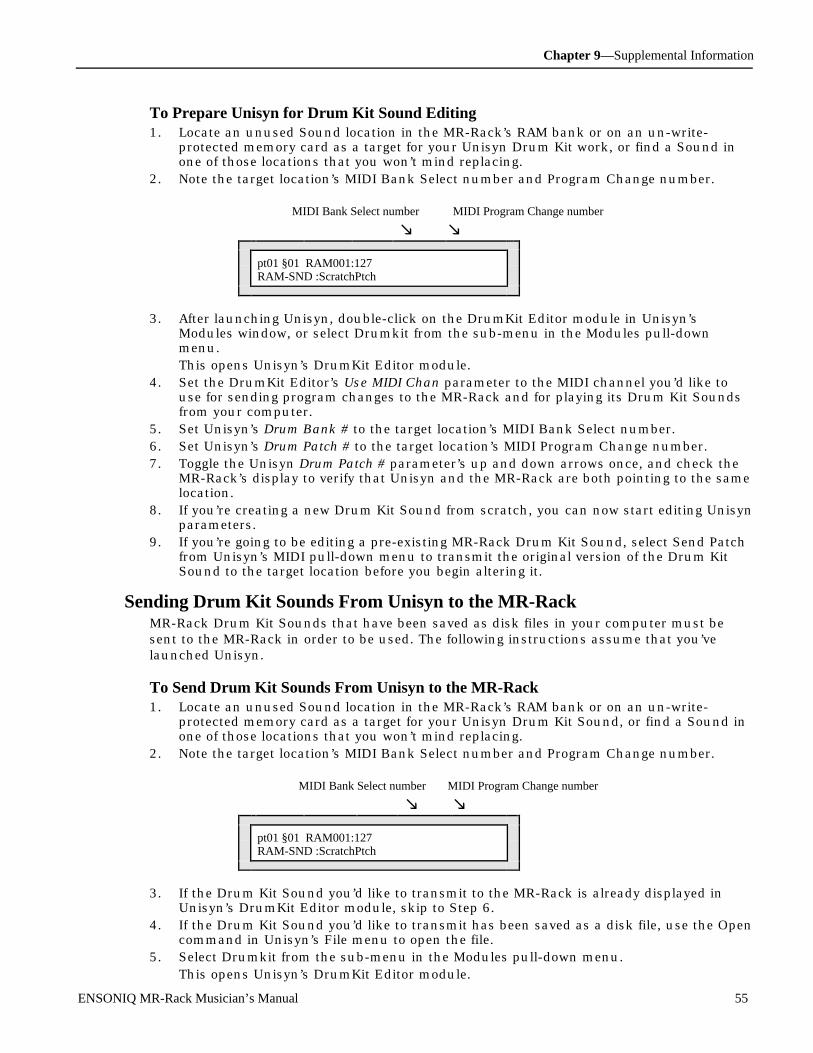
Chapter 9—Supplemental Information
ENSONIQ MR-Rack Musician’s Manual 55
To Prepare Unisyn for Drum Kit Sound Editing1. Locate an unused Sound location in the MR-Rack’s RAM bank or on an un-write-
protected memory card as a target for your Unisyn Drum Kit work, or find a Sound inone of those locations that you won’t mind replacing.
2. Note the target location’s MIDI Bank Select number and Program Change number.
MIDI Bank Select number MIDI Program Change number
m m
pt01 §01 RAM001:127RAM-SND :ScratchPtch
3. After launching Unisyn, double-click on the DrumKit Editor module in Unisyn’sModules window, or select Drumkit from the sub-menu in the Modules pull-downmenu.This opens Unisyn’s DrumKit Editor module.
4. Set the DrumKit Editor’s Use MIDI Chan parameter to the MIDI channel you’d like touse for sending program changes to the MR-Rack and for playing its Drum Kit Soundsfrom your computer.
5. Set Unisyn’s Drum Bank # to the target location’s MIDI Bank Select number.6. Set Unisyn’s Drum Patch # to the target location’s MIDI Program Change number.7. Toggle the Unisyn Drum Patch # parameter’s up and down arrows once, and check the
MR-Rack’s display to verify that Unisyn and the MR-Rack are both pointing to the samelocation.
8. If you’re creating a new Drum Kit Sound from scratch, you can now start editing Unisynparameters.
9. If you’re going to be editing a pre-existing MR-Rack Drum Kit Sound, select Send Patchfrom Unisyn’s MIDI pull-down menu to transmit the original version of the Drum KitSound to the target location before you begin altering it.
Sending Drum Kit Sounds From Unisyn to the MR-RackMR-Rack Drum Kit Sounds that have been saved as disk files in your computer must besent to the MR-Rack in order to be used. The following instructions assume that you’velaunched Unisyn.
To Send Drum Kit Sounds From Unisyn to the MR-Rack1. Locate an unused Sound location in the MR-Rack’s RAM bank or on an un-write-
protected memory card as a target for your Unisyn Drum Kit Sound, or find a Sound inone of those locations that you won’t mind replacing.
2. Note the target location’s MIDI Bank Select number and Program Change number.
MIDI Bank Select number MIDI Program Change number
m m
pt01 §01 RAM001:127RAM-SND :ScratchPtch
3. If the Drum Kit Sound you’d like to transmit to the MR-Rack is already displayed inUnisyn’s DrumKit Editor module, skip to Step 6.
4. If the Drum Kit Sound you’d like to transmit has been saved as a disk file, use the Opencommand in Unisyn’s File menu to open the file.
5. Select Drumkit from the sub-menu in the Modules pull-down menu.This opens Unisyn’s DrumKit Editor module.

Chapter 9—Supplemental Information
56 ENSONIQ MR-Rack Musician’s Manual
6. Set Unisyn’s Send Use MIDI Chan parameter to the MIDI channel you’d like to use forsending program changes to the MR-Rack and for playing its Drum Kit Sounds fromyour computer.
7. Set Unisyn’s Drum Bank # to the target location’s MIDI Bank Select number.8. Set Unisyn’s Drum Patch # to the target location’s MIDI Program Change number.9. Toggle the Unisyn Drum Patch # parameter’s up and down arrows once, and check the
MR-Rack’s display to verify that Unisyn and the MR-Rack are both pointing to the sametarget location.
10. Select Send Patch from Unisyn’s MIDI pull-down menu to transmit the Drum Kit Soundto the MR-Rack.
DrumKit Editor OverviewDrum Kit Sounds in the MR-Rack can access up to 64 standard Sounds at a single time,with each of those Sounds mapped to a single key, called a DrumKey (If you’d like, multipleDrumKeys can access the same Sound).
Note: Drum Kits identify Sounds by their locations in the MR-Rack’s memory. If theSounds are moved, or removed, the Drum Kit must be redirected to the Sound’s newlocation, or to another Sound.
Each DrumKey has a suite of parameters for tailoring the Sound it’s using to your needs.The Unisyn DrumKit Editor provides computer access to the same Drum Kit Sound Partparameters available from the MR-Rack’s front panel when a Drum Kit Sound is assigned tothe selected Part.
DrumKey ParametersThe following parameters affect individual DrumKeys.
Edit DrumKeySelects a DrumKey within the current PerfEditKit for editing.Range: B1 to D7
DrumKey BankDetermines the MR-Rack bank in which the Sound assigned to the selected DrumKeyresides.Range: 0 to 127
DrumKey ProgramDetermines the Sound that the selected DrumKey will use.Range: 0 to 127
FX BusDetermines the FX Bus routing of the selected DrumKey.Range: Insert, LiteVerb, MediumVerb, WetVerb, Dry
VolumeOffsets the programmed volume of the Sound assigned to the selected DrumKey.Adjustments are measured in deciBels.Range: -50 to 14
PanOffsets the programmed stereo panning of the Sound assigned to the selected DrumKey.A 0 value uses the Sound’s programmed panning; negative values shift the Soundleftward; positive values shift it to the right.

Chapter 9—Supplemental Information
ENSONIQ MR-Rack Musician’s Manual 57
Range: -64 to 63
Tuning ShiftRetunes the Sound assigned to the selected DrumKey by keyboard steps. Amount ofpitch change depends on the Key Track value programmed into the Sound.Range: -64 to 63
Drum Kit ParametersThe following parameters determine the characteristics of the entire Drum Kit Sound.
Kit CategoryDetermines the Drum Kit’s SoundFinder Sound Type instrument category.Range: SoundFinder categories
Demo Kit?Enables/disables inclusion of the Drum Kit in the DEMO-SND SoundFinder SoundType category.Range: Off, On
User Kit?Enables/disables inclusion of the Drum Kit in the USER-SND SoundFinder Sound Typecategory. The USER-SND category provides easy access to Sounds you’ve createdyourself.Range: Off, On
Drum Bank #Selects the bank in the MR-Rack from which a Drum Kit Sound (Patch) # is chosen as atarget for Drum Kit edits or for Unisyn’s Get Patch command (see Drum Patch # below).Range: 0 to 127
Drum Patch #Selects a Sound location within the Sound Bank chosen above. Drum Kit Sounds maybe retrieved from this location using Unisyn’s Get Patch command, and Unisyn Soundedits are written to this location as they occur.Range: 0 to 127
Use MIDI ChanDetermines the MIDI channel used to send MIDI Bank Selects and Program Changesfrom Unisyn to the MR-Rack. It also selects the MIDI channel that can be used to playthe MR-Rack’s Drum Kit Sound from Unisyn.Range: Channel 1-Channel 16
Use Handshake?Enables/disables the ability of Unisyn and the MR-Rack to confirm edits behind thescenes . When set to Off, Unisyn sends edits, but receives no confirmation back fromthe MR-Rack; when set to On, MR-Rack invisibly confirms receipt of edit data.Range: No (off-line), Yes (Live)
Send Insert FX?Enables/disables sending of Drum Kit Sound’s Insert Effect to the MR-Rack, if there’sone present.Range: Off, On
Note: Insert Effects can be assigned to a Drum Kit Sound only in the MR-Rack itself,when the Sound is assigned to a Part that’s routed to the Insert FX Bus and hasbeen designated as the Insert Control Part (Unisyn has no way of accomplishing
Chapter 9—Supplemental Information
58 ENSONIQ MR-Rack Musician’s Manual
this). Once the Drum Kit Sound has been assigned an Insert Effect, performing a GetPatch command in Unisyn will retrieve the Drum Kit Sound with its Insert Effect,which will be displayed in the read-only Insert FX Name field in the Unisyn DrumKitEditor.
Input MixIf the Drum Kit Sound has an Insert Effect, this parameter determines the relativebalance between the Drum Kit as it is before going through the Insert Effect (dry), andas it is after the going through the Insert Effect (wet). A value of 0 is all dry, a value of127 is all wet.Range: 0 to 127
Insert Cho MixIf the Drum Kit Sound has an Insert Effect, this parameter determines the relativebalance between the Drum Kit as it is after going through the Insert Effect, and as it isafter it’s gone through the Global Chorus. A value of 0 is all Insert Effect, a value of 127is all Chorus.Range: 0 to 127
InsertRvb AmtDetermines the amount of the Global Reverb added to the Insert Effect by adjusting theamount of the Insert Effect being sent into the Global Reverb.Range: 0 to 127
Insert FX Namea read-only display listing the Insert Effect retrieved with the current Drum Kit after aUnisyn Get Patch command is performed.Range: read-only
U sing the U nisyn Pe r f orm (P e r f or m anc e ) Edit or There are two general areas of new knowledge required for using the Unisyn MR-RackPerformance Editor:
• the methods for moving Performances back and forth between your computer and theMR-Rack
• the capabilities of the Performance Editor itself
Getting the Current Performance From the MR-Rack to UnisynThe Unisyn Performance Editor always retrieves the MR-Rack’s current Performance.
To Move the Current MR-Rack Performance Into Unisyn1. On the MR-Rack, select the Performance you’d like to retrieve into your computer, and
into Unisyn.2. After launching Unisyn, double-click on the Perform Editor module in Unisyn’s Modules
window, or select Perform from the sub-menu in the Modules pull-down menu.This opens Unisyn’s Performance Editor module—you’ll probably want to expand it toits full view.
3. Select Get Patch from Unisyn’s MIDI menu.In a moment, the current MR-Rack Performance will be transferred into the UnisynPerform Editor.
Creating New Sounds and Editing Pre-Existing Performances with UnisynWhen Unisyn creates or edits an MR-Rack Performance, it instantly sends the new data tothe MR-Rack’s edit buffer (for details on the Performance edit buffer, see “The Safe-Keeping

Chapter 9—Supplemental Information
ENSONIQ MR-Rack Musician’s Manual 59
of Part Edits” in Chapter 4). The edited Performance must the be saved using the Save: ThisPerformance command in order to be made permanent (see “Saving the CurrentPerformance” in Chapter 6).
To Prepare Unisyn for Sound Editing1. After launching Unisyn, double-click on the Perform Editor module in Unisyn’s Modules
window, or select Performance from the sub-menu in the Modules pull-down menu.This opens Unisyn’s Performance Editor module—you’ll probably want to expand it toits full view.
2. If you’re creating a new Performance from scratch, or if you’ve just retrieved thePerformance to be edited from the MR-Rack, you can now start editing Unisynparameters.
3. If you’re going to be editing a pre-existing MR-Rack Performance that you’ve loaded intoUnisyn from a disk file, select Send Patch from Unisyn’s MIDI pull-down menu totransmit the Performance to the MR-Rack before you begin altering it.
Note: Remember to save the edited Performance to a location in the MR-Rack’smemory using the Save:ThisPerformance command (see “Saving the CurrentPerformance” in Chapter 6).
Sending a Performance From Unisyn to the MR-RackMR-Rack Performances that have been saved as disk files in your computer must be sent tothe MR-Rack in order to be used. The following instructions assume that you’ve launchedUnisyn.
To Send a Performance From Unisyn to the MR-Rack1. If the Performance you’d like to transmit to the MR-Rack is already displayed in
Unisyn’s Performance Editor module, skip to Step 6.2. If the Performance you’d like to transmit has been saved as a disk file, use the Open
command in Unisyn’s File menu to open the file.3. Double-click on the Performance’s name in Unisyn’s Modules window, or select Perform
from the sub-menu in the Modules pull-down menu.This opens Unisyn’s Performance Editor module—you’ll probably want to expand it toits full view.
4. Select Send Patch from Unisyn’s MIDI pull-down menu to transmit the Performance tothe MR-Rack.
Note: Remember to save the edited Performance to a location in the MR-Rack’smemory using the Save:ThisPerformance command (see “Saving the CurrentPerformance” in Chapter 6).
Perform (Performance) Editor OverviewA Performance is a collection of all of the settings of the MR-Rack’s 16 Parts, as well as thesettings of the Insert Effect, Global Chorus and Global Reverb. Performances provide andeasy way to store and access MR-Rack set-ups. The Unisyn Perform (Performance) Editorprovides computer access to the same Performance parameters accessed by the MR-Rack’sfront panel Sound, Params and Effects buttons.
Part Assign ParametersThese parameters provide quick access to Mute/Solo status, MIDI channel, Bank andSound assignment parameters for all 16 Parts.
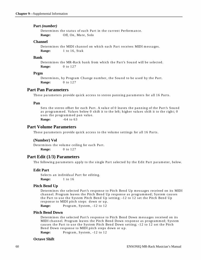
Chapter 9—Supplemental Information
60 ENSONIQ MR-Rack Musician’s Manual
Part (number)Determines the status of each Part in the current Performance.Range: Off, On, Mute, Solo
ChannelDetermines the MIDI channel on which each Part receives MIDI messages.Range: 1 to 16, Stak
BankDetermines the MR-Rack bank from which the Part’s Sound will be selected.Range: 0 to 127
PrgmDetermines, by Program Change number, the Sound to be used by the Part.Range: 0 to 127
Part Pan ParametersThese parameters provide quick access to stereo panning parameters for all 16 Parts.
PanSets the stereo offset for each Part. A value of 0 leaves the panning of the Part’s Soundas programmed. Values below 0 shift it to the left; higher values shift it to the right; 0uses the programmed pan value.Range: -64 to 63
Part Volume ParametersThese parameters provide quick access to the volume settings for all 16 Parts.
(Number) VolDetermines the volume ceiling for each Part.
Range: 0 to 127
Part Edit (1/3) ParametersThe following parameters apply to the single Part selected by the Edit Part parameter, below.
Edit PartSelects an individual Part for editing.Range: 1 to 16
Pitch Bend UpDetermines the selected Part’s response to Pitch Bend Up messages received on its MIDIchannel. Program leaves the Pitch Bend Up response as programmed; System causesthe Part to use the System Pitch Bend Up setting; -12 to 12 set the Pitch Bend Upresponse to MIDI pitch steps down or up.Range: Program, System, -12 to 12
Pitch Bend DownDetermines the selected Part’s response to Pitch Bend Down messages received on itsMIDI channel. Program leaves the Pitch Bend Down response as programmed; Systemcauses the Part to use the System Pitch Bend Down setting; -12 to 12 set the PitchBend Down response to MIDI pitch steps down or up.Range: Program, System, -12 to 12
Octave Shift
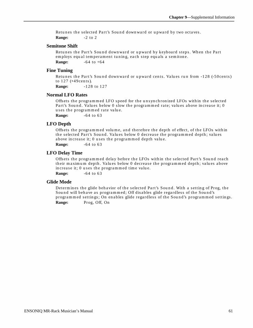
Chapter 9—Supplemental Information
ENSONIQ MR-Rack Musician’s Manual 61
Retunes the selected Part’s Sound downward or upward by two octaves.Range: -2 to 2
Semitone ShiftRetunes the Part’s Sound downward or upward by keyboard steps. When the Partemploys equal temperament tuning, each step equals a semitone.Range: -64 to +64
Fine TuningRetunes the Part’s Sound downward or upward cents. Values run from -128 (-50cents)to 127 (+49cents).Range: -128 to 127
Normal LFO RatesOffsets the programmed LFO speed for the unsynchronized LFOs within the selectedPart’s Sound. Values below 0 slow the programmed rate; values above increase it; 0uses the programmed rate value.Range: -64 to 63
LFO DepthOffsets the programmed volume, and therefore the depth of effect, of the LFOs withinthe selected Part’s Sound. Values below 0 decrease the programmed depth; valuesabove increase it; 0 uses the programmed depth value.Range: -64 to 63
LFO Delay TimeOffsets the programmed delay before the LFOs within the selected Part’s Sound reachtheir maximum depth. Values below 0 decrease the programmed depth; values aboveincrease it; 0 uses the programmed time value.Range: -64 to 63
Glide ModeDetermines the glide behavior of the selected Part’s Sound. With a setting of Prog, theSound will behave as programmed; Off disables glide regardless of the Sound’sprogrammed settings; On enables glide regardless of the Sound’s programmed settings.Range: Prog, Off, On
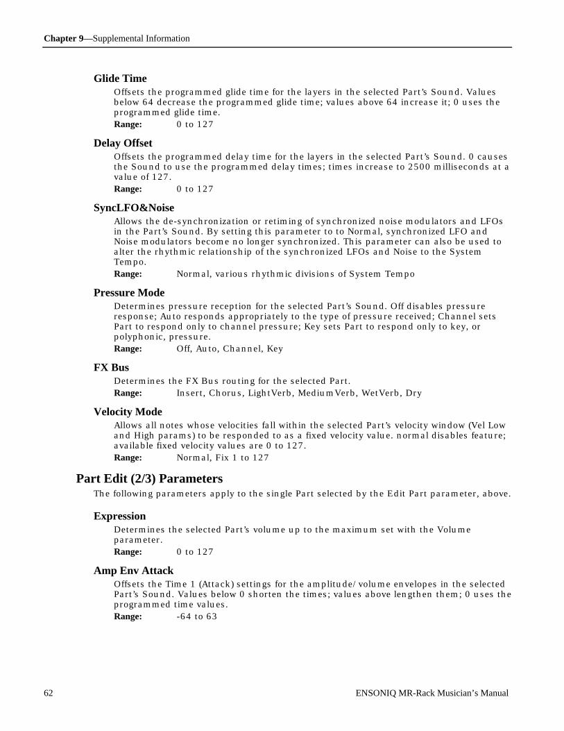
Chapter 9—Supplemental Information
62 ENSONIQ MR-Rack Musician’s Manual
Glide TimeOffsets the programmed glide time for the layers in the selected Part’s Sound. Valuesbelow 64 decrease the programmed glide time; values above 64 increase it; 0 uses theprogrammed glide time.Range: 0 to 127
Delay OffsetOffsets the programmed delay time for the layers in the selected Part’s Sound. 0 causesthe Sound to use the programmed delay times; times increase to 2500 milliseconds at avalue of 127.Range: 0 to 127
SyncLFO&NoiseAllows the de-synchronization or retiming of synchronized noise modulators and LFOsin the Part’s Sound. By setting this parameter to to Normal, synchronized LFO andNoise modulators become no longer synchronized. This parameter can also be used toalter the rhythmic relationship of the synchronized LFOs and Noise to the SystemTempo.Range: Normal, various rhythmic divisions of System Tempo
Pressure ModeDetermines pressure reception for the selected Part’s Sound. Off disables pressureresponse; Auto responds appropriately to the type of pressure received; Channel setsPart to respond only to channel pressure; Key sets Part to respond only to key, orpolyphonic, pressure.Range: Off, Auto, Channel, Key
FX BusDetermines the FX Bus routing for the selected Part.Range: Insert, Chorus, LightVerb, MediumVerb, WetVerb, Dry
Velocity ModeAllows all notes whose velocities fall within the selected Part’s velocity window (Vel Lowand High params) to be responded to as a fixed velocity value. normal disables feature;available fixed velocity values are 0 to 127.Range: Normal, Fix 1 to 127
Part Edit (2/3) ParametersThe following parameters apply to the single Part selected by the Edit Part parameter, above.
ExpressionDetermines the selected Part’s volume up to the maximum set with the Volumeparameter.Range: 0 to 127
Amp Env AttackOffsets the Time 1 (Attack) settings for the amplitude/volume envelopes in the selectedPart’s Sound. Values below 0 shorten the times; values above lengthen them; 0 uses theprogrammed time values.Range: -64 to 63

Chapter 9—Supplemental Information
ENSONIQ MR-Rack Musician’s Manual 63
Amp Env DecayOffsets the Time 2, 3 and 4 settings for the amplitude/volume envelopes in the selectedPart’s Sound. Values below 0 shorten the times; values above lengthen them; 0 uses theprogrammed time values.Range: -64 to 63
Amp Env ReleaseOffsets the Time 5 (Release) settings for the amplitude/volume envelopes in the selectedPart’s Sound. Values below 0 shorten the times; values above lengthen them; 0 uses theprogrammed time values.Range: -64 to 63
Filt Env AttackOffsets the Time 1 (Attack) settings for the filter envelopes in the selected Part’s Sound.Values below 0 shorten the times; values above lengthen them; 0 uses the programmedtime values.Range: -64 to 63
Filt Env DecayOffsets the Time 2, 3 and 4 settings for the filter envelopes in the selected Part’s Sound.Values below 0 shorten the times; values above lengthen them; 0 uses the programmedtime values.Range: -64 to 63
Filt Env ReleaseOffsets the Time 5 (Release) settings for the filter envelopes in the selected Part’s Sound.Values below 0 shorten the times; values above lengthen them; 0 uses the programmedtime values.Range: -64 to 63
Filter CutoffOffsets the filter cutoff frequencies for the filters in the selected Part’s Sound. Valuesbelow 0 lower the cutoff settings; values above raise them; 0 uses the programmedcutoff values.Range: -64 to 63
Amp&Filt VelOffsets the velocity-sensitivity of the amplitude and filter envelopes in the selected Part’sSound. Values below 0 decrease their sensitivity; values above increase it; 0 uses theprogrammed velocity sensitivity.Range: -64 to 63
Vel LowDetermines the low boundary of the selected Part’s velocity window. Received velocitiesbelow this value will be ignored by Part.Range: 0 to 127
Vel HighDetermines the high boundary of the selected Part’s velocity window. Received velocitieswill be ignored by Part.Range: 0 to 127

Chapter 9—Supplemental Information
64 ENSONIQ MR-Rack Musician’s Manual
Key LowDetermines the low boundary of the selected Part’s pitch-reception window. ReceivedMIDI notes lower than this value will be ignored by Part.Range: A0 to C8
Key HighDetermines the high boundary of the selected Part’s pitch-reception window. ReceivedMIDI notes higher than this value will be ignored by Part.Range: A0 to C8
Part Edit (3/3) ParametersThe following parameters apply to the single Part selected by the Edit Part parameter, above.
Prog Change RecvEnables/disables Part’s reception of MIDI Program Changes.Range: On, Off
Bank Change RecvEnables/disables Part’s reception of MIDI Bank Selects.Range: On, Off
Data Entry RecvEnables/disables Part’s reception of MIDI Data Entry messages.Range: On, Off
Pitch Bend RecvEnables/disables Part’s reception of MIDI Pitch Bend messages.Range: On, Off
Mod Wheel RecvEnables/disables Part’s reception of MIDI Mod Wheel messages.Range: On, Off
Foot Pedal RecvEnables/disables Part’s reception of MIDI Foot Pedal messages.Range: On, Off
Volume RecvEnables/disables Part’s reception of MIDI Volume messages.Range: On, Off
Pan RecvEnables/disables Part’s reception of MIDI Pan messages.Range: On, Off
Sustain RecvEnables/disables Part’s reception of MIDI Sustain messages.Range: On, Off

Chapter 9—Supplemental Information
ENSONIQ MR-Rack Musician’s Manual 65
Volume PolarityDetermines Part’s response to MIDI Volume messages. Positive causes Part to respondnormally (lower values lower volume, higher values raise it); Negative inverts response(lower values raise volume; higher values lower it).Range: Positive, Negative
Pitch TableAllows selected Part to use a special pitch table. Program chooses Sound’s programmedpitch table assignment; System chooses the System pitch table; RAM chooses the RAMpitch table; pitch tables stored in ROM may also be selected.Range: Program, System, various ROM Pitch Tables, RAM
SysCTRL1 RecvEnables/disables Part’s reception of assignable controller SysCTRL 1’s messages.Range: On, Off
SysCTRL2 RecvEnables/disables Part’s reception of assignable controller SysCTRL 2’s messages.Range: On, Off
SysCTRL3 RecvEnables/disables Part’s reception of assignable controller SysCTRL 3’s messages.Range: On, Off
SysCTRL4 RecvEnables/disables Part’s reception of assignable controller SysCTRL 4’s messages.Range: On, Off
ReverbThe following parameters apply to the current Performance’s Global Reverb.
Reverb RoutingThe following parameters determine the amounts of signal sent on the three Global ReverbFX busses and the overall Global Reverb level.
LiteVerb SendDetermines the amount of dry signal sent to the Global Reverb via the LightReverb FXBus.Range: 0 to 63
MediumVerb SendDetermines the amount of dry signal sent to the Global Reverb via the MediumReverbFX Bus.Range: 32 to 95
WetVerb SendDetermines the amount of dry signal sent to the Global Reverb via the WetReverb FXBus.Range: 64 to 127
Return LevelDetermines the overall output volume of the Global Reverb.Range: 0 to 127

Chapter 9—Supplemental Information
66 ENSONIQ MR-Rack Musician’s Manual
Reverb ParamsThe following parameters determine the qualities of the Global Reverb.
DecayDetermines the time it takes for the Global Reverb to fade to silence after being excitedby an input signal.Range: 0 to 100
HF DampingDetermines the threshold frequency at which damping begins as Global Reverb decays .Values run from 0 (100 Hz) to 127 (21.2 kHz).Range: 0 to 127
HF BandwidthDetermines the threshold frequency above which frequencies are attenuated in theGlobal Reverb. Values run from 0 (100 Hz) to 127 (21.2 kHz).Range: 0 to 127
Diffusion 1Determines the amount of smearing of attack transients in the Global Reverb.Range: 0 to 100
Diffusion 2Determines the amount of smearing of attack transients in the Global Reverb; optimizedfor low-frequency transients.Range: 0 to 100
DefinitionDetermines the density of reflections in the Global Reverb as it decays.Range: 0 to 100
ChorusThe following parameters apply to the current Performance’s Global Chorus.
Chorus RoutingThe following parameters determine what happens to Sounds directed to the Chorus FXBus.
Input MixSets the wet/dry balance between the dry signal routed to the Chorus FX Bus and theoutput of the Global Chorus.Range: 0 to 127
Reverb AmountDetermines the amount of Global Reverb added to the Global Chorus output.Range: 0 to 127
Chorus ParamsThe following parameters determine the qualities of the Global Chorus.
LFO RateDetermines the speed at which the Global Chorus’s center delay time transforms fromits shortest value to its longest. Values run from 0 (0.0 Hz) to 127 (20.0 Hz).

Chapter 9—Supplemental Information
ENSONIQ MR-Rack Musician’s Manual 67
Range: 0 to 116
Chorus DepthDetermines the amount by which the Global Chorus’s center delay time shortens andlengthens. Values run from 0 (0.0 Hz) to 127 (25.0 Hz).Range: 0 to 250
Chorus CenterDetermines the center delay time of the two delays within the Global Chorus. Valuesrun from 0 (0.0 Hz) to 127 (25.0 Hz).Range: 0 to 500
Chorus SpreadDetermines the amount of stereo imaging in the Global Chorus.Range: 0 to 10
Chorus PhaseEnables/disables the synchronization of the Global Chorus’s pair of delays as theytravel from their shortest length to longest. 0 causes the delays to change together; 1causes one delay to shorten while the other lengthens, and vice versa.Range: 0, 1
InsertThe following parameters apply to the current Performance’s Insert Effect.
Insert RoutingThe following parameters determine what happens to Sounds directed to the Insert FX Busand designate an Insert Control Part.
Input MixSets the wet/dry balance between the dry signal routed to the Insert FX Bus and theoutput of the Insert Effect.Range: 0 to 127
Chorus MixDetermines the amount of Global Chorus added to the Insert Effect by setting a wet/drybalance between the output of the Insert Effect being sent into the Global Chorus andthe output of the Global Chorus.Range: 0 to 127
Reverb AmountDetermines the amount of the Global Reverb added to the Insert Effect by adjusting theamount of the Insert Effect being sent into the Global Reverb.Range: 0 to 127
Insert Typea read-only display listing the Insert Effect retrieved with the current Performance aftera Unisyn Get Patch command is performed.Range: read-only
Note: Insert Effects can be assigned to a Performance only in the MR-Rack itself.Once the Performance has been assigned an Insert Effect, executing a Get Patchcommand in Unisyn will retrieve the Performance with its Insert Effect, which will bedisplayed in this read-only field in the Unisyn Perform Editor.

Chapter 9—Supplemental Information
68 ENSONIQ MR-Rack Musician’s Manual
Control PartDetermines which Part in the current Performance will contribute newly-selectedSounds’ Insert Effect as the Performance Insert Effect. Also determines which Part willreceive real-time controllers for modulation of the Insert Effect. May also be set to Off,for no Insert Control Part.Range: Off, 1 to 16
Output AssignsThe following parameters determine the rear-panel output jack routing of the currentPerformance’s Effects and Dry FX Bus.
Reverb OutputDetermines to which rear-panel jacks the output of the Global Reverb will be routed.Range: Main, Aux
Chorus OutputDetermines to which rear-panel jacks the output of the Global Chorus will be routed.Range: Main, Aux
Insert OutputDetermines to which rear-panel jacks the output of the Insert Effect will be routed.Range: Main, Aux
Dry Bus OutputDetermines to which rear-panel jacks Sounds sent to the Dry FX Bus will be routed.Range: Main, Aux
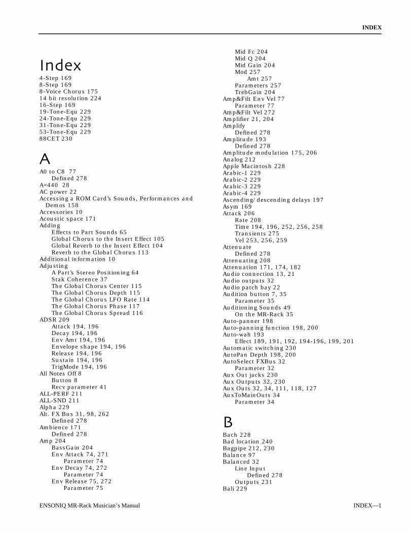
INDEX
ENSONIQ MR-Rack Musician’s Manual INDEX—1
4-Step 1698-Step 1698-Voice Chorus 17514 bit resolution 22416-Step 16919-Tone-Equ 22924-Tone-Equ 22931-Tone-Equ 22953-Tone-Equ 22988CET 230
A0 to C8 77Defined 278
A=440 28AC power 22Accessing a ROM Card’s Sounds, Performances and
Demos 158Accessories 10Acoustic space 171Adding
Effects to Part Sounds 65Global Chorus to the Insert Effect 105Global Reverb to the Insert Effect 104Reverb to the Global Chorus 113
Additional information 10Adjusting
A Part’s Stereo Positioning 64Stak Coherence 37The Global Chorus Center 115The Global Chorus Depth 115The Global Chorus LFO Rate 114The Global Chorus Phase 117The Global Chorus Spread 116
ADSR 209Attack 194, 196Decay 194, 196Env Amt 194, 196Envelope shape 194, 196Release 194, 196Sustain 194, 196TrigMode 194, 196
All Notes Off 8Button 8Recv parameter 41
ALL-PERF 211ALL-SND 211Alpha 229Alt. FX Bus 31, 98, 262
Defined 278Ambience 171
Defined 278Amp 204
BassGain 204Env Attack 74, 271
Parameter 74Env Decay 74, 272
Parameter 74Env Release 75, 272
Parameter 75
Mid Fc 204Mid Q 204Mid Gain 204Mod 257
Amt 257Parameters 257TrebGain 204
Amp&Filt Env Vel 77Parameter 77
Amp&Filt Vel 272Amplifier 21, 204Amplify
Defined 278Amplitude 193
Defined 278Amplitude modulation 175, 206Analog 212Apple Macintosh 228Arabic-1 229Arabic-2 229Arabic-3 229Arabic-4 229Ascending/descending delays 197Asym 169Attack 206
Rate 208Time 194, 196, 252, 256, 258Transients 275Vel 253, 256, 259
AttenuateDefined 278
Attenuating 208Attenuation 171, 174, 182Audio connection 13, 21Audio outputs 32Audio patch bay 22Audition button 7, 35
Parameter 35Auditioning Sounds 49
On the MR-Rack 35Auto-panner 198Auto-panning function 198, 200Auto-wah 193
Effect 189, 191, 192, 194-196, 199, 201Automatic switching 230AutoPan Depth 198, 200AutoSelect FXBus 32
Parameter 32Aux Out jacks 230Aux Outputs 32, 230Aux Outs 32, 34, 111, 118, 127AuxToMainOuts 34
Parameter 34
Bach 228Bad location 240Bagpipe 212, 230Balance 97Balanced 32
Line InputDefined 278
Outputs 231Bali 229

INDEX
INDEX—2 ENSONIQ MR-Rack Musician’s Manual
Bandwidth 170, 176, 182, 188, 190-192, 195, 201-205, 207-209
Defined 278Parameter 124
Bank 5, 269Defined 278Change Recv 273Select 39, 40, 81, 82
Defined 278LSB 48Message 5Recv 81Recv parameter 81
Bank&ProgChgRecv parameter 39, 40BASS 211BASS-SYN 211Battery 8, 158
Low Warning 8BELL 211Bend Down 27, 245Bend Up 27, 245Beta scale 229Bias Attack 204Bias Release 204Books 10Boost 170, 182, 188, 190-192, 195, 201-209BRASSECT 211BRASSOLO 211Buffer 239
Defined 278Bus 4
Settings 4Busses 97Buzz 189, 192, 195, 199, 201, 205, 207Bypass 130Bypassing and Un-Bypassing with the Bypass
Parameter 131Bypassing and Un-Bypassing With the Effects Button
129Bypassing Effects 128
C4Defined 278
Can’t write there! 239Cancellation 183Card 240
Battery low 240Formatting a PCMCIA 154Slot 6Write Protect! 240
CarlosAlpha 229Beta 229Gamma 230Wendy 230
Cavernous 174Center frequency 191, 203, 208Center Offset 176Central device 215Changing a DrumKey’s
Effect 91Panning 90Sound by its
Program Change Number 89Sound Name 88
Tuning 92Volume 89
Changing a Part’s Key Range 77Changing Performances Via MIDI 38Changing the Source of a DrumKey’s Sound 87Channel 168, 244, 269
Pressure 80Chatter Box 198, 199Checksum 240China 229Chinese lute tuning 229Chinese-1 229Chinese-2 229Choosing
A Real-Time Insert Effect Modulator 106A Sound for a Part 48Performances on the MR-Rack 4Sounds 2
Chords 236Chorus 31, 65, 91, 105, 112, 176, 179, 184, 189,
209, 2758-Voice 175Bus 97Center 175-177, 179, 184, 190, 209, 276
Parameter 115Depth 175-177, 179, 184, 190, 209, 276
Parameter 115Feedback 176FX Bus 4
Global Reverb Amount parameter 113LFO Rate 114Mix 177Params 276Phase 175, 176, 276
Parameter 117Preset 96, 112Rate 175, 176, 179, 184, 209Spread 175, 184, 190Stereo 175Routing 275Spread 276
Parameter 116Chorus→Rev 179ChorusCenter 175, 176, 184, 190Chorused effect 230Chorusing 197, 198, 200
Defined 278Classes 213Classic rotating speaker effect 200Clicking 188Clipping 169, 170, 182, 187-192, 195, 198, 199,
201-203, 205, 207-209Clock 29Coloration 173Command 133
Saving 134To abort a 133
CompAttack 206, 208Output 206, 208PreDelay 208Ratio 206, 208Release 206, 208Thresh 206, 208

INDEX
ENSONIQ MR-Rack Musician’s Manual INDEX—3
Compression 206, 208Defined 278Ratio
Defined 278Compressor 208Computer 15-19, 20, 23, 43, 214, 232, 241
Editor 237Manufacturers 214Programs 41Sequencer 17
Confirming Your MIDI Connection 23Connections 13
Making MIDI 13Controller 14, 15, 17, 18, 20, 23, 24, 84, 86, 107,
168, 216, 232, 245, 274Controlling a Part’s Loudness 63Controlling a Part’s Pitch Bend Response 66Controlling the Shape of Part Sounds 74Copy Functions 143Copying
Layer Parameters 242PCMCIA Card
Performances to RAM 144Sounds to RAM 147
RAMPerformances to a PCMCIA Card 143Sounds to a PCMCIA Card 146
Corrupted 240CRD-PERF 211CRD-SND 211Creating New Drum Kit Sounds, Editing Pre-Existing
Sounds with Unisyn 263Creating New Sounds and Editing Pre-Existing
Performances with Unisyn 268Creating New Standard Sounds or Editing Pre-
Existing Sounds 242Crossover frequency 201CTRL
Defined 278Ctrl High 248Ctrl Low 248Curves 169, 190, 207CUSTOM 212Customer Service 166Customizing Part LFOs 71Cut 170, 182, 188, 190-192, 195, 201-209Cutoff frequency 170, 176, 182, 188, 190-192, 194-
196, 201, 202, 204, 205, 207-209, 255Defined 278
CV Pedal 189, 191-196, 199, 201Cycle
Defined 278
Dampen 171, 177, 178, 180-183Damping 184-187, 189, 194-196, 199, 200, 204,
206, 207, 209, 210Defined 278
Data card 43Slot 6, 43, 156
Data Entry Recv 82, 273Parameter 82
Databases 5DDL
Defined 279Mod Center 183Mod Depth 183Signal 198
DDL→Chorus 184Decay 171, 172, 174, 176-183, 275Decay time 194, 196Decibels 206, 208Definition 127, 171-174, 177-183, 275Delay 171, 186, 194, 196, 206, 209, 249, 261
Modulation 175Offset 71, 271Time 172, 184-187, 188, 194, 196, 198-200,
204-207, 209, 210Delaying Part Sounds 71Demo 7, 35, 36
Kit? 266Song 7Sound? 246
DEMO-SND 211Demonstration songs 7Demos
Playing Other 7Density 173
Defined 173Density 1 173Density 2 173Depth 261
Mod 261Amt 261
Destination 105Max parameter 110Min parameter 110
Detection sustain time 209Determining
The Behavior of the Aux Outs 34Whether a Part’s Sound Will Glide 69Determining Which MR-Rack Outputs
The Global Chorus Will Use 118The Global Reverb Will Use 127The Insert Effect Will Use 110
Detune Depth 171Detune Rate 171Detuning 171, 175, 188, 201, 202Didjeridoo 212Diffus Time 188Diffuse 174, 181, 183Diffuser 172, 188Diffusion 125, 171-174, 176-183, 188, 275
Defined 279Digital delay 184-188, 194, 195, 205, 206Direction 251Discrete echoes 172, 174, 178Disk drive 15Display 6Dist
Curve 169, 189, 190, 192, 195, 199, 201, 205,207
Dry Lev 189, 191, 192, 195, 199, 201, 205, 207Gain 189, 190, 192, 193, 195, 199, 200, 205,
207LPF Fc 189, 190, 192, 195, 199, 200, 205, 207Offset 189, 190, 192, 195, 199, 200, 205, 207Volume 189, 190, 192, 193, 195, 199, 201, 205,
207Dist→AutoWah 193

INDEX
INDEX—4 ENSONIQ MR-Rack Musician’s Manual
Dist→Chorus 189Dist→Flanger 190Dist→VCF→DDL 195Distorter 199Distortion 24, 189, 190, 192, 193, 195, 200, 201,
203-207Curves 169DDL signal 199Filter cutoff frequency 193
DelayDamping 184-187, 189, 194-196, 199, 200, 204,
206, 207, 209, 210Feedback 184-188, 194-196, 198-200, 204, 206,
207, 209, 210Interval 188Level 184-187, 189, 194-196, 198-200, 204-207,
209, 210Max Level 189Pan 184-187, 189, 194-196, 204-207, 209, 210Smoothing 188Spread 189Time 184-187, 194, 196, 198-200, 204-207, 209,
210Doppler 201, 202DRM-SND 211DRMKITGM 85, 211Drum BankDrum Key 55, 86, 87, 137, 265
Bank 265Defined 279Effect 91Panning 90Parameters 265Program 265Sound 88Sound Type 87Tuning 92Volume 89
Drum Kit 5, 85, 87, 211Editor 241
Overview 265Using 263
Key 55Perf Edit Kit 55Saving 92Parameters 266Sound 5, 55, 85, 137, 263
Defined 279Drum maps 217Drum PatchDrums 172Dry 65, 91, 95, 97, 103
Blend 176, 209Bus 98, 128Defined 279Effect 97
Bus 128FX Bus 4Signal 184, 195, 196, 207
Dump<dump type> Sending... 240Functions 139
Dumping 216All RAM Performances 141All RAM Sounds 141The Current Part’s Sound 140
The Current PerfEditKit 139The Current Performance 139
Dweep-dweep sound 193
Early reflection (ER) 175Defined 279Levels 171, 172, 175Send 171-173Time 171-173
Earning the Logo 217Echo 171-173, 176-183
Density 171, 172, 174, 177, 178, 180, 181Effects 198
EditBuffer 52Context Parameters 246DrumKey 265Layer 247Part 269
Editing Drum Kits 85Editing Parts 49Editing Sounds with the MR-Rack and a Computer
16Editing the Insert Effect 101Editor 241Effect 4, 49
Bus parameter 31Bus setting 98Chain 205, 206, 209Defined 279Modulators 106, 168Parameters 262Processor 4
Effects 4, 65, 95, 167Button 95, 101, 107Bypassing 128
Parameter 131, 132Chip 99Devices 214Diagram 99Processor 14Red LED 132Setup
Initializing a 149Saving 135
Understanding 95Busses 97
Eight voices 176Electro Static Discharge (ESD) 162
An Important Note About 162Enable 247Enabling and Disabling Part Response to MIDI
Controllers 82Enabling and Disabling System Exclusive
Communication 41ENSONIQ Customer Service 166ENSONIQ drum map 85Enter button 52Envelope 74, 194, 196, 244, 255
Amt 250, 255Defined 279Follower 194Level 173
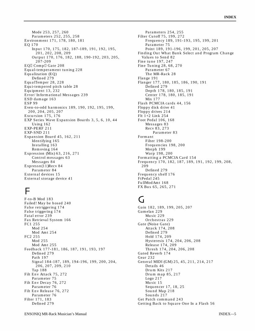
INDEX
ENSONIQ MR-Rack Musician’s Manual INDEX—5
Mode 253, 257, 260Parameters 252, 255, 258
Environment 171, 178, 180, 181EQ 170
Input 170, 175, 182, 187-189, 191, 192, 195,201, 202, 208, 209
Output 170, 176, 182, 188, 190-192, 203, 205,207-209
EQ→Comp→Gate 208Equal-temperament tuning 228Equalization (EQ)
Defined 279EqualTemper 28, 228Equi-tempered pitch table 28Equipment 13, 232Error/Informational Messages 239ESD damage 163ESP 99Even-to-odd harmonics 189, 190, 192, 195, 199,
200, 204, 205, 207Excursion 175, 176EXP Series Wave Expansion Boards 3, 5, 6, 10, 44
Using 162EXP-PERF 211EXP-SND 211Expansion Board 45, 162, 211
Identifying 165Installing 163Removing 164
Expression (Mix) 63, 216, 271Control messages 63Messages 84
Expressn(11)Recv 84Parameter 84
External devices 15External storage device 41
F-to-B Mod 183Failed! May be hosed 240False retriggering 174False triggering 174Fatal error 239Fax Retrieval System 166FC1 255
Mod 254Mod Amt 254
FC2 255Mod 255Mod Amt 255
Feedback 177-181, 186, 187, 191, 193, 197Defined 279Path 197Signal 184-187, 189, 194-196, 199, 200, 204,
206, 207, 209, 210Tap 188
Filt Env Attack 75, 272Parameter 75
Filt Env Decay 76, 272Parameter 76
Filt Env Release 76, 272Parameter 76
Filter 171, 183Defined 279
Parameters 254, 255Filter Cutoff 75, 199, 272
Frequency 189, 191-193, 195, 199, 201Parameter 75Point 189, 191-196, 199, 201, 205, 207
Finding Out What Bank Select and Program ChangeValues to Send 82
Fine tune 197, 247Fine Tuning 28, 68, 270
Parameter 67The MR-Rack 28
Flange 191Flanger 177, 180, 185, 186, 190, 191
Defined 279Depth 178, 180, 185, 191Center 178, 180, 185, 191Mix 177
Flash PCMCIA cards 44, 156Floppy disk drive 41Floppy drives 214Flt 1+2 Link 254Foot Pedal 106, 168
Messages 83Recv 83, 273
Parameter 83Formant
Filter 198-200Frequencies 198, 200Morph 199Warp 198, 200
Formatting a PCMCIA Card 154Frequency 170, 182, 187, 189, 191, 192, 199, 208,
209Defined 279
Frequency shelf 176FtPedal 245FullModAmt 168FX Bus 65, 265, 271
Gain 182, 189, 199, 205, 207Gamelan 229
Music 229Orchestras 229
Gate (Noise Gate)Attack 174, 208Defined 279Hold 174, 209Hysteresis 174, 204, 206, 208Release 174, 209Thresh 174, 204, 206, 208
Gated Reverb 174Gear 232General MIDI (GM) 25, 45, 211, 214, 217
Details 46Drum Kits 217Drum map 85, 217Logo 217Music 15Sequencer 17, 18, 25Sound Map 218Sounds 217
Get Patch command 243Getting Back to Square One In a Flash 56

INDEX
INDEX—6 ENSONIQ MR-Rack Musician’s Manual
Getting Pre-Existing Drum Kit Sounds From the MR-Rack Into Unisyn 263
Getting Pre-Existing Standard Sounds From the MR-Rack Into Unisyn 241
Getting Ready to Listen 1Getting the Current Performance From the MR-Rack
to Unisyn 267Glide 248
Mode 69, 70, 270Parameter 69, 70
Time 71, 248, 271Global
Defined 279Global Chorus 4, 49, 65, 95, 96, 105, 275
Parameter 111Preset parameter 96Presets 112Working with the 111
Global Pitch Bend 28Up and Down 27
Global Reverb 4, 49, 65, 95, 96, 104, 274Amount 104, 114, 120-122Definition 127High-Frequency Damping 124Output Assign 33Preset parameter 96Presets 119Working with the 118
Global Tempo Clock Source 30Glossary 278Glowing tube 204GM 36
Alias 245GM and GS Percussion Key Maps (Channel 10) 219,
220GM-PERF 211GM-SND 211Greek music 229Grk-Chromat 229Grk-Diatonc 229Grk-Enharm 229Ground Compensated Outputs 231Ground loop 231
Problems 231Grounded AC outlet 22Group solo 57, 59Guitar 204, 205, 206, 209Guitar Amp 203Guitar amplifier 24GUITAR-A 212GUITAR-E 212
Half steps 197Hall 172Hall Reverb 171, 172Handshake 246Hard 189
Disks 214Drive 41Reinitialization 9
Harmonic 229Content 199
Harmonics 204
Headphones 1, 21, 231Jack 231
Height 193Held 27Held PBend 246HF Bandwidth 124, 171-173, 176-183, 275HF Damping 171-174, 176-183, 275Hi AM Max 201Hi AM Min 201Hi Fast 201Hi FM Max 201Hi FM Min 201Hi Inertia 201Hi Slow 201High density reverb 171High Frequency 123, 171, 173, 176-183, 189, 192,
195, 199, 204, 205, 207Bandwidth 124, 171, 173, 176-181, 204Energy 173, 174, 181Shelf 170, 182, 188, 190-192, 205, 207-209
High impedance headphones 231High Key 248High pass filter 176, 202, 254High shelving filter 204HiShelf Fc 170, 182, 188, 190-192, 208, 209HiShelf Gain 170, 182, 188, 190-192, 205, 207-209Hit ENTER for GM! 25, 45HITS 212Hold Time 174Hole-punched paper 216Home enthusiasts 214Home stereo 21, 24How MIDI Channels Work 215How MIDI Messages Work 216How Sound-Related Part Parameters Work 55How the MR-Rack’s Memory Works 5HPF Cutoff 176, 203Hum 231Hysteresis 174
Defined 279
IBM-compatible computer 3, 241Identifying Installed Wave Expansion Boards 44If Sounds Are Behaving Unexpectedly 234If the MR-Rack Doesn’t Play 232If the Sounds You’re Hearing Sound Unexpectedly
Strange 235If You Experience Odd Behavior 9If You’re Hearing Music You Don’t Expect to Hear
236If You’re Hearing Sounds You Don’t Expect to Hear
232If You’re Seeing One Sound on the Display but
Hearing Another 233If You’re Selecting New Sounds But What You Hear
Remains the Same 234Impulse sounds 172, 174, 176, 177, 178Indian-Raga 229Indonesia 229Infinity 206, 208Init
ThisPart'sSound Can’t initialize! 239ThisPart’sSound 239
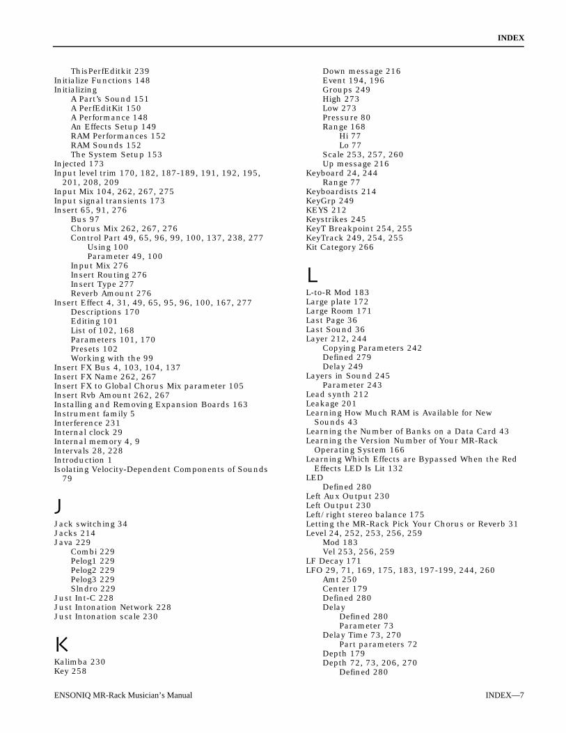
INDEX
ENSONIQ MR-Rack Musician’s Manual INDEX—7
ThisPerfEditkit 239Initialize Functions 148Initializing
A Part’s Sound 151A PerfEditKit 150A Performance 148An Effects Setup 149RAM Performances 152RAM Sounds 152The System Setup 153
Injected 173Input level trim 170, 182, 187-189, 191, 192, 195,
201, 208, 209Input Mix 104, 262, 267, 275Input signal transients 173Insert 65, 91, 276
Bus 97Chorus Mix 262, 267, 276Control Part 49, 65, 96, 99, 100, 137, 238, 277
Using 100Parameter 49, 100
Input Mix 276Insert Routing 276Insert Type 277Reverb Amount 276
Insert Effect 4, 31, 49, 65, 95, 96, 100, 167, 277Descriptions 170Editing 101List of 102, 168Parameters 101, 170Presets 102Working with the 99
Insert FX Bus 4, 103, 104, 137Insert FX Name 262, 267Insert FX to Global Chorus Mix parameter 105Insert Rvb Amount 262, 267Installing and Removing Expansion Boards 163Instrument family 5Interference 231Internal clock 29Internal memory 4, 9Intervals 28, 228Introduction 1Isolating Velocity-Dependent Components of Sounds
79
Jack switching 34Jacks 214Java 229
Combi 229Pelog1 229Pelog2 229Pelog3 229Slndro 229
Just Int-C 228Just Intonation Network 228Just Intonation scale 230
Kalimba 230Key 258
Down message 216Event 194, 196Groups 249High 273Low 273Pressure 80Range 168
Hi 77Lo 77
Scale 253, 257, 260Up message 216
Keyboard 24, 244Range 77
Keyboardists 214KeyGrp 249KEYS 212Keystrikes 245KeyT Breakpoint 254, 255KeyTrack 249, 254, 255Kit Category 266
L-to-R Mod 183Large plate 172Large Room 171Last Page 36Last Sound 36Layer 212, 244
Copying Parameters 242Defined 279Delay 249
Layers in Sound 245Parameter 243
Lead synth 212Leakage 201Learning How Much RAM is Available for New
Sounds 43Learning the Number of Banks on a Data Card 43Learning the Version Number of Your MR-Rack
Operating System 166Learning Which Effects are Bypassed When the Red
Effects LED Is Lit 132LED
Defined 280Left Aux Output 230Left Output 230Left/right stereo balance 175Letting the MR-Rack Pick Your Chorus or Reverb 31Level 24, 252, 253, 256, 259
Mod 183Vel 253, 256, 259
LF Decay 171LFO 29, 71, 169, 175, 183, 197-199, 244, 260
Amt 250Center 179Defined 280Delay
Defined 280Parameter 73
Delay Time 73, 270Part parameters 72
Depth 179Depth 72, 73, 206, 270
Defined 280
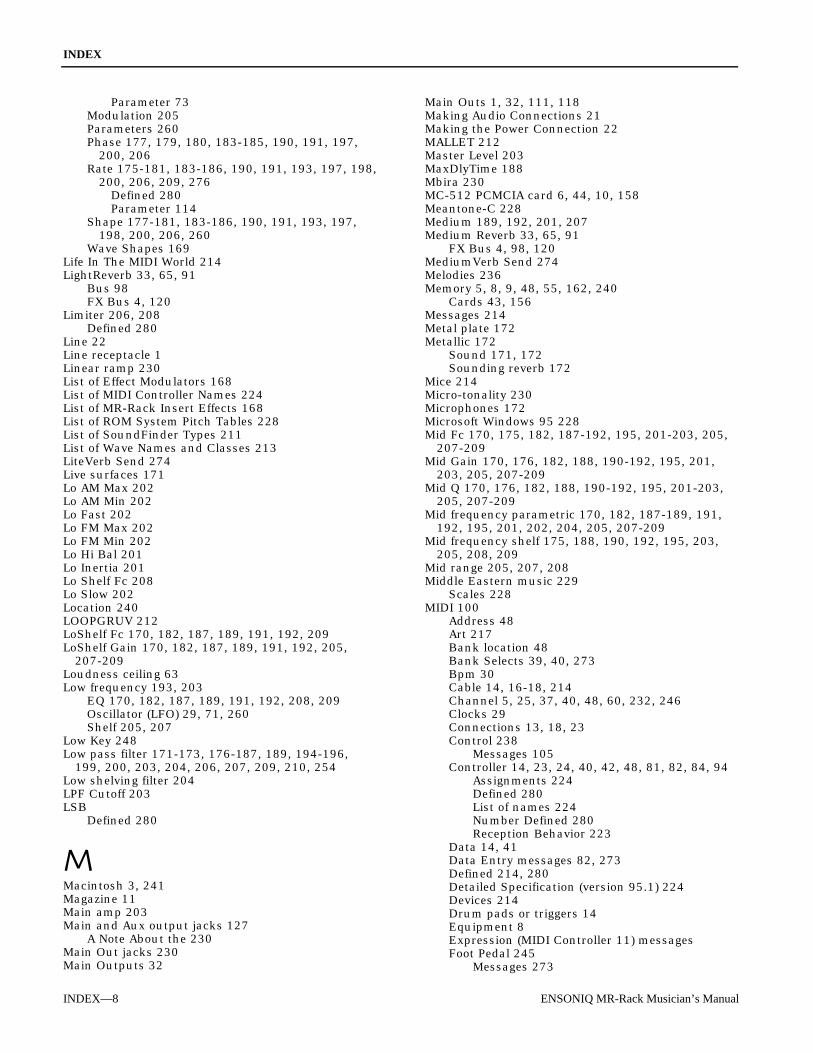
INDEX
INDEX—8 ENSONIQ MR-Rack Musician’s Manual
Parameter 73Modulation 205Parameters 260Phase 177, 179, 180, 183-185, 190, 191, 197,
200, 206Rate 175-181, 183-186, 190, 191, 193, 197, 198,
200, 206, 209, 276Defined 280Parameter 114
Shape 177-181, 183-186, 190, 191, 193, 197,198, 200, 206, 260
Wave Shapes 169Life In The MIDI World 214LightReverb 33, 65, 91
Bus 98FX Bus 4, 120
Limiter 206, 208Defined 280
Line 22Line receptacle 1Linear ramp 230List of Effect Modulators 168List of MIDI Controller Names 224List of MR-Rack Insert Effects 168List of ROM System Pitch Tables 228List of SoundFinder Types 211List of Wave Names and Classes 213LiteVerb Send 274Live surfaces 171Lo AM Max 202Lo AM Min 202Lo Fast 202Lo FM Max 202Lo FM Min 202Lo Hi Bal 201Lo Inertia 201Lo Shelf Fc 208Lo Slow 202Location 240LOOPGRUV 212LoShelf Fc 170, 182, 187, 189, 191, 192, 209LoShelf Gain 170, 182, 187, 189, 191, 192, 205,
207-209Loudness ceiling 63Low frequency 193, 203
EQ 170, 182, 187, 189, 191, 192, 208, 209Oscillator (LFO) 29, 71, 260Shelf 205, 207
Low Key 248Low pass filter 171-173, 176-187, 189, 194-196,
199, 200, 203, 204, 206, 207, 209, 210, 254Low shelving filter 204LPF Cutoff 203LSB
Defined 280
Macintosh 3, 241Magazine 11Main amp 203Main and Aux output jacks 127
A Note About the 230Main Out jacks 230Main Outputs 32
Main Outs 1, 32, 111, 118Making Audio Connections 21Making the Power Connection 22MALLET 212Master Level 203MaxDlyTime 188Mbira 230MC-512 PCMCIA card 6, 44, 10, 158Meantone-C 228Medium 189, 192, 201, 207Medium Reverb 33, 65, 91
FX Bus 4, 98, 120MediumVerb Send 274Melodies 236Memory 5, 8, 9, 48, 55, 162, 240
Cards 43, 156Messages 214Metal plate 172Metallic 172
Sound 171, 172Sounding reverb 172
Mice 214Micro-tonality 230Microphones 172Microsoft Windows 95 228Mid Fc 170, 175, 182, 187-192, 195, 201-203, 205,
207-209Mid Gain 170, 176, 182, 188, 190-192, 195, 201,
203, 205, 207-209Mid Q 170, 176, 182, 188, 190-192, 195, 201-203,
205, 207-209Mid frequency parametric 170, 182, 187-189, 191,
192, 195, 201, 202, 204, 205, 207-209Mid frequency shelf 175, 188, 190, 192, 195, 203,
205, 208, 209Mid range 205, 207, 208Middle Eastern music 229
Scales 228MIDI 100
Address 48Art 217Bank location 48Bank Selects 39, 40, 273Bpm 30Cable 14, 16-18, 214Channel 5, 25, 37, 40, 48, 60, 232, 246Clocks 29Connections 13, 18, 23Control 238
Messages 105Controller 14, 23, 24, 40, 42, 48, 81, 82, 84, 94
Assignments 224Defined 280List of names 224Number Defined 280Reception Behavior 223
Data 14, 41Data Entry messages 82, 273Defined 214, 280Detailed Specification (version 95.1) 224Devices 214Drum pads or triggers 14Equipment 8Expression (MIDI Controller 11) messagesFoot Pedal 245
Messages 273

INDEX
ENSONIQ MR-Rack Musician’s Manual INDEX—9
Guitars 14Hardware 214Implementation Chart 222In jack 214Interface 16, 17, 18, 19Key 244Key note number 106Keyboard 14, 86Light 23Manufacturer's Association 228Merger 15, 18
Defined 280Modulation Wheel 244
Messages 273Music 15Note number 244, 254, 258Out jack 214Pan messages 273Patchbay 19, 23, 232Patcher 14, 15, 16Pitch Bend 244
Messages 26, 66, 83, 249, 273Pitch table Bulk Tuning Dump 28Powering on 22Program number 48Program Change 5, 38, 48, 216, 273Recorded performances 214Recording 216Rig 215, 232Sequencing programs 17Sockets 214Sustain and Sostenuto messages 84Sustain messages 249, 273System Exclusive (SysEx) 41, 142, 240
Data 15, 41Thru jack 214Tuning Standard 228Velocity 244
Messages 79Volume 63
Messages 273, 274Mixed stereo 231Mixer faders 13Mixing console 21, 22, 24, 214Mod Amt 249Mod Range 250Mod Wheel 106, 168, 202, 238, 244
Messages 83Recv 83, 273
Parameter 83Mode 254Modem cards 44, 156Modulate 238Modulating the Insert Effect in Real Time 105Modulation 105, 108, 168, 177, 178, 181, 184-186,
190Defined 280Real Time 108
Modulation Source 105Modulator 202, 237, 238
Defined 280Effects 168
Monophonic 249Morph 198, 199Moving On 25MR-Rack
General MIDI Details for the Curious 46MIDI Implementation 221Understanding 3
MRC Series ROM Sound card 6, 43, 156MSB
Defined 280Multi 194, 196Multi-Tap DDL 188Multi-timbral 215
Device 236Multimedia 217Music lovers 214Musical arrangements 214Musical instrument 214
Digital Interface 214, 221Musicians 214Mute 57, 58, 60
Button 57, 58, 59Muted 236
Parts 60Muting and Soloing Parts 57Myriad 214
NamesMIDI Controller 224
Need More Help? 10No Card Inserted! 240Noise
Defined 280Gate 204, 206, 208Generators 71Rate 258Sync 258
Non-Registered Parameter 226Numbers 94
NonLinReverb 173Normal 202Normal LFO
Defined 280Rates 73, 270
Parameter 72, 73Notch Depth 178, 180, 181, 185, 186, 191, 193Notches 178-181, 185-187, 191, 193Note-off 253NRPN 226NRPNs 94
O.S. Version 166Octave 197
Shift 67, 270Offset parameters 56Operating system
Finding the 166Updating 166Operating system upgrade 166
Optional accessories 10Options 26ORCHSTRA 212ORGAN-A 212ORGAN-E 212

INDEX
INDEX—10 ENSONIQ MR-Rack Musician’s Manual
ORGANLYR 212Oscillating pitch shift 171Other Points of Interest 8OTTO 99Output 118, 127
Amplitude envelope 174Assign parameter 33Assigns 33, 111, 277
Chorus Output 277Dry Bus Output 277Insert Output 277Reverb Output 277
Bal 172, 173, 175Circuit
Headphones 231Jacks 110, 118Tap levels 173
Override parameter 55Overview 1Oww-oww sound 193
Pan 247, 266, 269Defined 280Messages 84Mod 258
Amt 258Part parameter 65Recv 84, 273
Parameter 84Setting 64
Panic button 8Panic messages 40Panner 183Param Reset 225Parameter 26, 49, 95, 167
Copying Layer 242Defined 280Dumping System 142Part 51
ParametricEQ 170, 182, 187, 188, 205, 206, 209
Defined 280Filter 203
Params button 50Part 48, 137
Assign Parameters 269Assignments 4Delay Offset 71
Parameter 71Edit (1/3) Parameters 269Edit (2/3) Parameters 271Edit (3/3) Parameters 273Edits
Protecting 56Glide Mode 69
Parameter 69, 70LFOs 71Loudness 63MIDI channel 50, 78MIDI reception filters 225Muting a 58Number 50, 269Pan Parameters 269
Pan Setting 64Param Reset 30, 31, 225
Parameter 30, 31, 70Parameter 3, 50-52, 56, 94
Sound Related 55Routing to an effect 65Setting its MIDI Channel 60Settings
Protecting 30Soloing a 59
Group 60Sound Residency 48Stereo Positioning 64To Select a 47Un-Muting a 58Un-Soloing a 59Un-Soloing from a Group 60Volume 63
Parameter 63, 269Part’s Sound 137
Initializing a 151Partch
Harry 230Partch-43 (pitch table) 230Parts 3, 47
Editing 49Patch Bay 19, 24
Defined 280PBend 249PCMCIA Card 6, 43, 158, 211
Formatting a 154Inserted Registering... 240ROM card 10Removed Unregistering... 240SRAM card 10Using 156
PCMCIA PerformancesCopying 144
PCMCIA SoundsCopying 147
Peaks 178-181, 185-187, 191, 193Pelog 229
Scale 229PERC-KIT 85, 212PERCSOLO 212Percussion 172, 173
Drum Kits 85Instruments 174Sounds 5
Perf Edit Kit 5, 55, 85, 86, 92, 212Dumping 139Initializing a 150Saving 136
Perf ProgChgRecv parameter 38, 39Perform (Performance) Editor 241, 269
Overview 269Performance 4, 47, 51, 52, 56, 96, 240, 268, 277
Button 4, 6, 24, 51, 52Choosing a 4Defined 280Dumping 139Edit Kit 5, 85Editor 267Saving a 52, 134Sending from Unisyn 268To Select a 47

INDEX
ENSONIQ MR-Rack Musician’s Manual INDEX—11
Types 5, 211Performances 5, 211
Copying PCMCIA 144Copying RAM 143Dumping RAM 141Initializing a 148Initializing RAM 152
Performing a System Parameters Dump 142Personal computer 214, 217Phase 183, 261Phase shifter 178, 181, 186, 192Phaser 178, 181, 186, 193
Center 178, 181, 186, 193Defined 280Depth 178, 181, 186, 193Mix 178
Phones jack 1, 21, 24, 231PIANO-A 212PIANO-E 212Pierce-Bohl 230Pitch 27, 175, 252
Detuner 197Mod 249Modulation 177, 179-181, 184-186, 190, 191,
193, 197, 198, 200Modulator 249Parameters 249Table 28, 29, 68, 245, 274
Defined 228, 281Using 68
Pitch Bend 28, 246Down 27, 66, 67, 270Messages 83Mode 27Recv 83, 273
Parameter 66, 83Up 27, 66, 270Wheel 26, 66, 106, 168 238, 244
Pitch Tables and the MIDI Tuning Standard Format228
Pizzicato strings 212Plate reverb 172, 176, 177, 178, 180Player pianos 216Playing Other Demos 7Playing the MR-Rack Demo 7PLUCKED 212PNOLYR-A 212PNOLYR-E 212Pole 254Poly 168PolyKey 80, 244Polyphonic 244, 249
Pressure 80Synth Sounds 212
Polyphony 14Portamento 69, 248Position 1 172Position 2 172Position 3 172Post HP Fc 204Post HPF Fc 194Post VCF Fc 189, 191, 192, 194, 195, 199, 201, 205,
207Post VCF Q 189, 191, 192, 194, 195, 199, 201, 205,
207PostEQ Level 204
PostVCF EnvAmt 194Power 13
Button 1Cable 22Connections 13Cord 22Supply 22
Powering Up 1, 22Pre EQ
Fc 203Gain 203Q 203Trim 203
Pre HP Fc 202, 203Pre HPF Fc 193Pre VCF Fc 193Pre VCF Q 193Pre-echo 171, 173Preamp Gain 203, 204PreDelay 171, 172Presence 189, 191, 192, 194-196, 199, 201Presets 102Pressure 80, 106, 168, 244
Mode 80, 271Parameter 80
PreVCF EnvAmt 193Prgm 269Primary Send 171, 173Program Change 38, 39, 40, 81 82
Defined 281Recv 81, 273
Parameter 81Message 6, 81Number 89Values 48
Prompt 36Protecting Part Settings 30Protecting the MR-Rack’s Memory 36Protecting Your Part Edits 56Protocols 217Pythagorean 228Pythagrn-C 228
Q 189, 191-196, 199, 201, 205, 207Defined 281Setting 203
Quarter tones 229Quick Bypass of All Effects with the Bypass
Parameter 132
Ragas 229RAM 6, 230, 239
Memory 211Banks 6
PerformancesCopying 143Dumping 141Initializing 152
Pitch tables 230Sounds
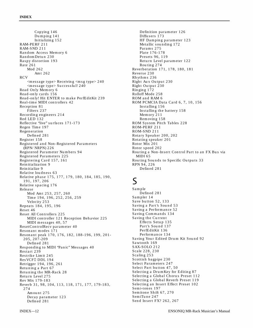
INDEX
INDEX—12 ENSONIQ MR-Rack Musician’s Manual
Copying 146Dumping 141Initializing 152
RAM-PERF 211RAM-SND 211Random Access Memory 6RandomDetun 230Raspy distortion 193Rate 261
Mod 262Amt 262
RCV<message type> Receiving <msg type> 240<message type> Successful! 240
Read Only Memory 6Read-only cards 156Read-only! Hit ENTER to make PerfEditKit 239Real-time MIDI controllers 42Reception 81
Filters 237Recording engineers 214Red LED 132Reflective “live” surfaces 171-173Regen Time 197Regeneration
Defined 281Register 158Registered and Non-Registered Parameters
(RPN/NRPN) 226Registered Parameter Numbers 94Registered Parameters 225Registering Card 157, 161Reinitialization 9Reinitialize 9Relative loudness 63Relative phase 175, 177, 179, 180, 184, 185, 190,
191, 197, 206Relative spacing 176Release
Mod Amt 253, 257, 260Time 194, 196, 252, 256, 259Velocity 253
Repeats 184, 195, 196Reset 46Reset All Controllers 225
MIDI controller 121 Reception Behavior 225MIDI messages 40, 57
ResetControlRecv parameter 40Resonant modes 171Resonant peak 170, 176, 182, 188-196, 199, 201-
205, 207-209Defined 281
Responding to MIDI “Panic” Messages 40Restart 239Restrike Limit 245ResVCF→DDL 194Retrigger 194, 196, 261Retuning a Part 67Retuning the MR-Rack 28Return Level 275Rev Mix 179-183Reverb 31, 98, 104, 113, 118, 171, 177, 179-183,
274Amount 275Decay parameter 123Defined 281
Definition parameter 126Diffusers 173HF Damping parameter 123Metallic sounding 172Params 275Plate 176-178Presets 96, 119Return Level parameter 122Routing 274
Reverberation 171, 178, 180, 181Reverse 230Rhythms 236Right Aux Output 230Right Output 230Ringing 172Rolloff Mode 258ROM and RAM 6ROM PCMCIA Data Card 6, 7, 10, 156
Installing 156Installing the battery 158Memory 211Removing 158
ROM System Pitch Tables 228ROM-PERF 211ROM-SND 211Rotary Speaker 200, 202Rotating speaker 201Rotor Mix 201Rotor speed 202Routing a Non-Insert Control Part to an FX Bus via
MIDI 65Routing Sounds to Specific Outputs 33RPN 94, 226
Defined 281
SampleDefined 281
Sampler 14Save button 52, 133Saving a Part’s Sound 53Saving a Performance 52Saving Commands 134Saving the Current
Effects Setup 135Part’s Sound 137PerfEditKit 136Performance 134
Saving Your Edited Drum Kit Sound 92Sawtooth 169SAX-SOLO 212Scale 228, 230Scaling 253Scottish bagpipe 230Select Parameters 247Select Part button 47, 50Selecting a DrumKey for Editing 87Selecting a Global Chorus Preset 112Selecting a Global Reverb Preset 119Selecting an Insert Effect Preset 102Semi-tones 197Semitone Shift 67, 270SemiTune 247Send Insert FX? 262, 267

INDEX
ENSONIQ MR-Rack Musician’s Manual INDEX—13
Sending a Performance From Unisyn to the MR-Rack268
Sending Drum Kit Sounds From Unisyn to the MR-Rack 264
Sending Standard Sounds From Unisyn to the MR-Rack 243
Sending SysEx Data Back to the MR-Rack 143Sending the Aux Signals to the Headphones 231Sequencer 14, 15, 17, 214, 232Sequences 17Sequencing with the MR-Rack, a Computer and a
Controller 17Setting a Part’s Glide Time 70Setting a Part’s MIDI Channel 60Setting a Part's Response To MIDI Pressure Messages
80Setting Part Velocity Ranges 79Setting Reverb Amounts for the Light, Medium and
Wet Reverb Busses 120Setting the Allowable Amount of Real-Time Insert
Effect Modulation 109Setting the Global Pitch Bend Mode 27Setting the Global Reception of MIDI Bank Selects
and Program Changes 39Setting the Global Reverb’s
Brightness 124Decay Time 122Definition 126Diffusion 125High-Frequency Damping 123Volume 122
Setting the Insert Effect Parameter to be Modulatedin Real-Time 108
Setting the MR-Rack’s Response to All Notes Off MIDIMessages 40
Setting the MR-Rack’s Response to Reset AllControllers MIDI Messages 40
Setting the Real-Time Insert Effect ModulationReception Window 107
Setting the Stak MIDI Channel 37Setting Up New Real-Time Controllers 42Setting Volume Levels 24Settlinger’s Law 232Setup
Initializing the System 153Shakuhachi 212Shape 169, 184-186, 190, 191, 193, 197-200, 206Sharpness 205, 207Shift Amount 251Shift Mode 251ShonaMbira1 230ShonaMbira2 230Signal
Defined 281Level 174
Silent 236Sine 169Single 194, 196Single Note Tuning Change 28Slap Level 174Slap Time 174Slendro 229Slope (dB/oct) 258Small plate 172Small Room 171Smear 125, 171, 172, 174, 176-183
Smooth 244Smoother 197Smoothest sound 173Soft 189, 192, 195, 199, 201, 205, 207Soft reset 9Solo 57, 58Sorry! An Unexpected Event xxx occured. 239Sorry! Main battery 8, 239Sorry! No memory for sound sent from MIDI 240Sorry! Save to card failed. Check media 240Sorry! There is no memory available. 239Sorry! Too big. Hit ENTER to copy ##%.Sostenuto 84, 106, 168, 216
Pedal 245Sound 49, 240
BankButton 6, 48Category 2, 246Choosing for a Part 48Defined 281Dumping 140Editing program 43Editor 241
Module 241Overview 244
Grouping 5Map
General MIDI 218PatchSaving a 137
A Part’s 53Settings 245Type 2, 5, 48, 211, 246Wave 3, 55
Defined 281SOUND-FX 212SoundFinder™ 2, 5
Sound Type 48Types 211
Sounds 2, 3, 5, 55, 232, 235Auditioning 49Copying
PCMCIA 147RAM 146
Creating in Unisyn 242Creating New Drum Kit 263Dumping RAM 141Editing 242General MIDI 217Getting into Unisyn 241Initializing RAM 152Sending Drum Kit from the MR 263Sending Drum Kit from Unisyn 264Sending from Unisyn 243
Sounds That You Expect to Hear Are UnexpectedlySilent 236
Space 188Speaker 202
Cabinet 202, 203, 205, 207Cancellation 183LPF 204Simulator 193
Special Commands 133Speed 201
Control 202Spinner 183

INDEX
INDEX—14 ENSONIQ MR-Rack Musician’s Manual
Splice width 197Split 78
Defined 281SPLITS 212Spread 175, 184, 190, 201Square 169SRAM (Static RAM) PCMCIA data cards 6, 10, 43,
156, 158Batteries 158Initializing 161Installing 159, 161Removing 162Working with 158
Srutis 229Stage lights 214Stak 5, 37
Channel 48, 60Coherence parameter 37, 38Creating a 61Defined 281MIDI channel 37, 38, 39, 50, 78Using 61
Standard cables 231Standard Sound 55
Defined 281Start Index 251State-of-the-art 224Static 162Stepped 244Stereo
Amplifier 21Balance 172, 173Chorus 175Compressor 208Field 64, 172, 189Headphones 1, 14, 15, 18, 20, 24, 231Outputs 230Panning 90Space 198Spectrum 175, 184-187, 194-196, 204-207, 209,
210Storage 133, 158
Prompts and Messages 239Stretch 230
Tuning 230STRGSECT 212STRGSOLO 212SuperJust 230Sustain 84, 106, 168, 208, 209, 216, 249
Level 194, 196Off 253Pedal 202, 245Recv 273
Sustain/SostRecv 84Parameter 84
Sweep 178, 180, 185, 191Symphonic chorused sound 175SYN-COMP 212SYN-LEAD 212SYN-PAD 212SYN-VINT 212Sync LFO
Defined 281Sync’d 71Synchronize 71Synchronizing the MR-Rack to MIDI 29
SyncLFO&Noise 72, 271Parameter 72Part parameter 71
SYNOTHER 212Synthesized stereo field 175, 184, 190Synthesizer 14SysCTRL 168
Defined 281Recv 85, 274
System Exclusive (SysEx) 15, 41Data 216
Sending back to the MR 143Device ID number 41, 142Device ID parameter 41Dump18, 42, 142
Receiving a 143Headers 216Reception 240Recv parameter 41Specification 221
SystemAutoSelect FXBus parameter 98Button 26Clock
Defined 281Controller 42, 84, 85, 106, 278
Defined 281Feedback 177, 178Parameters
Dumping 142Pitch table 228Setup
Initializing 153Tempo 30Upgrades 166Write protect 239
System Write Protect On! ENTER overrides 239System Write Protect parameter 52System-wide settings 26
Tabletop boxes 214Tap levels 173Taps 188Temperament 228Tempo 29, 30, 108Testament 217Tetra chord 229Thailand 229The Art of MIDI 217The MR-Rack is Not Responding to Program Changes
or Bank Selects 237Three parametric filters 202Threshold 174, 204, 206, 208
Frequency 275Thumb-piano 230Thump 183Tibet 229Tibetan 229Time 252, 256, 258, 259Time-varying spectrum 198Timebase 261Toggle 202Tonal character 173, 175, 177, 184

INDEX
ENSONIQ MR-Rack Musician’s Manual INDEX—15
Tone control 171, 178, 181Transformer isolated output 231Transient 125, 171, 174, 176, 177, 181-183
Defined 281Transmit 233Transmitting devices 23Tremolo 206Triangle 169Trigger 174
Ctrl 248Level 174On 247
Trim control 194, 195Troubleshooting the MR-Rack 232TRS 230
Stereo cables 32TS mono cables 32Tube 189, 190, 192, 195, 199, 201, 205, 204, 207
Bias 204Distortion 203
Tunable Spkr 202Tuning 67, 228
Parameter 28Tuning Shift 266Turkish-A 229Turning General MIDI Off Via SysEx 227Turning General MIDI On Via SysEx 227
Un-bypass 129, 130Unbalanced 32
TS mono cables 230Understanding
Effect Busses 97MIDI 214Part Parameters 51The MR-Rack 3
Effects 95The Special Alt. FX Bus 98
Unexpected Event messages 9Unformatted card 240Unisyn 43
Editing software 55Editor 3, 43Software 241Sound editor 41
Universal Non-Real-Time SysEx General MIDI On/Off227
Unregistering 162Updating the MR-Rack Operating System 166Use Handshake? 246, 266Use Lyr 247Use MIDI Chan 246, 266User Kit? 266User Sound? 246USER-SND 211Using ENSONIQ EXP Series Wave Expansion Boards
162Using Headphones with the MR-Rack 231Using MIDI Program Changes 38Using MIDI SysEx 41Using PCMCIA Data Cards 156Using Pitch Tables 28Using RPNs and NRPNs to Edit Part Parameters 94
Using Special Pitch Tables 68Using Staks 61Using SysEx Device IDs 41Using the Chorus Bus Wet/Dry Mix 112Using the Global Pitch Bend Settings 26Using the Insert Control Part 100
To Determine the Insert Effect 100To Pick Insert Effects Via MIDI 100
Using the Insert FX Bus Input Mix 103Using the MR-Rack
For General MIDI Music 25Outputs 230To Play General MIDI Music 45With a Computer, Controller and MIDI Merger 18With a Computer, Controller and MIDI Patchbay
19With a Controller 14With a Stand-Alone Sequencer 15With a Workstation 14
Using the MR-Rack’s Four Outputs 32Using the Unisyn DrumKit Editor 263Using the Unisyn Perform (Performance) Editor 267Using the Unisyn Sound Editor 241Using XLR Outs with the MR-Rack 231UTILITY 212
Vallotti-C 228Value 26, 49, 95
Defined 281VCF 194, 195, 196, 205
Attack 194Dry Amt 198, 199Fc 194, 196, 207Input 194, 195, 198, 199Q 194, 196Release 194
Vel Curve 254, 257, 260Vel hi 248Vel High 272Vel lo 248Vel Low 272Vel+Pressure 168Velocity 80, 106, 168, 216, 244, 272
Mode 80, 271Parameter 80
Response curves 254, 257, 260VelocityRange Hi 79
Parameter 79VelocityRange Lo 79
Parameter 79Verifying That Your Real-Time Controller Is Enabled
107Vibrations 172Vibrato 29Vocal 198Vocalist 172Vocalized signal 198VOCALS 212Voice 249
Architecture 213Chip 99Fine 197Level 197

INDEX
INDEX—16 ENSONIQ MR-Rack Musician’s Manual
Mod 197Regen 197Semi 197Width 197
Vol/MixPolarity parameter 64Voltage 22Voltage-Controlled Filter 193, 194, 195
Defined 281Volume (dB) 90, 122, 201, 247, 265, 275
Knob 1, 24, 231Messages 83Polarity 274Recv 83, 273Settings 13
Volume(7)Recv parameter 83Vowel shapes 198, 199
Wah-wah 193Pedal 189, 191-196, 199, 201
WakeUpMode 45Parameter 35, 36, 45
Waking up 35Walls 172Warping 198, 200Wave Class 213, 250Wave expansion boards 7, 44, 55Wave Mod 251
Amt 251Wave Name 250Wave Parameters 250Waves 213, 244Welcome! 1Well-Tempered Clavier 228Werkmeister 228Wet 97, 103, 201Wet/dry balance 275, 276Wet/dry control 97, 103, 112WetReverb 33, 65, 91
Bus 98FX Bus 4, 120
WetVerb Send 274What Is General MIDI 217What Is MIDI 214Wheel 26, 66Wheel+Press 168When a Part Has Been Edited 51WINDREED 212Working With an Edited Performance That Hasn’t Yet
Been Saved 51Working with Dry Sounds 128Working with Program Changes and Bank Selects 81Working With ROM PCMCIA Data Cards 156Working With SRAM PCMCIA Data Cards 158Working With System MIDI Controllers 84Working with the Global Chorus 111Working with the Global Reverb 118Working with the Insert Effect 99workstation 14, 214World Wide Web 166
Site 250Write Protect 36
Prompt 36Wrkmeistr-C 228
Wrong checksum 240WS1 to WS3 230
XLR cable 231XLR Connector
Defined 281
You’re Trying to Modulate a Sound Via MIDI, ButNothing’s Happening 237
You’re Trying to Modulate an Effect Via MIDI, ButNothing’s Happening 238