MR Angiography Edition – Issue 53
30
MAGNETOM Flash The Magazine of MRI Issue Number 3/2013 | MR Angiography Edition 53 Non-Contrast MRA: FSD-Prepared 3D Balanced SSFP Page 2 Non-Contrast ECG-Gated QISS MRA of the Lower Extremities at 3T Page 8 Respiratory Self-Navigation for Free Breathing Whole-Heart Coronary MRI Page 12 Combining Throughput and Highest Quality MRA in an Optimized Clinical Workflow Page 26 Advancements in the ECG-Gated Contrast-Enhanced MR Angiography Page 32 How-I-do-it 3D Navigator-Gated, IR FLASH with Blood Pool Contrast Agent Page 18 Contrast-Enhanced MRA in Practice: Tips and Caveats Page 40 Not for distribution in the US
-
Upload
jhon-arriaga-cordova -
Category
Documents
-
view
105 -
download
1
description
Transcript of MR Angiography Edition – Issue 53

MAGNETOM FlashThe Magazine of MRI
Issue Number 3/2013 | MR Angiography Edition
53
Non-Contrast MRA: FSD-Prepared 3D Balanced SSFP Page 2
Non-Contrast ECG-Gated QISS MRA of the Lower Extremities at 3T Page 8
Respiratory Self-Navigation for Free Breathing Whole-Heart Coronary MRI Page 12
Combining Throughput and Highest Quality MRA in an Optimized Clinical Workflow Page 26
Advancements in the ECG-Gated Contrast-Enhanced MR Angiography Page 32
How-I-do-it3D Navigator-Gated, IR FLASH with Blood Pool Contrast Agent Page 18
Contrast-Enhanced MRA in Practice: Tips and Caveats Page 40
Not for distribution in the US

module can introduce a spatial signal modulation in static tissues, as shown below, if the center 180° RF pulse frequency response is spatially inhomogeneous.
Mz =(–cos Θ sin2 Ф + cos2 Ф) × M0 [1]
Ф(r) = γ × r × A [2]
Where Mz is the longitudinal magneti-zation right after FSD-preparation, M0 is the equilibrium magnetization, Θ is the actual flip angle of the 180°-pulse, Ф is the phase the static spins accumulate during the FSD gra-dient before the 180°-pulse, which is dependent of the gradient’s net area A, r is the spatial variable along the gradient direction, and γ is the gyro-magnetic ratio. The period, λ, of the spatial signal modulation is defined as:
λ = [3]
A simple solution to circumventing the issue is to have Ф, or A, equal to zero. A bipolar-gradient scheme (Fig. 2B) becomes a natural choice to achieve this goal. Example images using the two gradient waveforms are shown in figures 2C and D.
(1A) Schematic of the FSD-prepared balanced SSFP technique. In the bright-artery acquisition, both arterial blood, venous blood, and other tissues are of high signal intensity. In the dark-artery measurement, arterial blood signals are mostly suppressed by FSD-preparation because of substantially fast flow. Thus, arterial blood signals remain and the signals of venous blood and background tissues are essentially cancelled out upon image subtraction. (1B) The sequence diagram of the bright-artery acquisition (T2-prepared balanced SSFP). (1C) The sequence diagram of the dark-artery acquisition (FSD-prepared balanced SSFP). G = FSD gradients, S = spoiler gradients.
1
Non-Contrast MR Angiography: Flow-Sensitive Dephasing (FSD)-Prepared 3D Balanced SSFPZhaoyang Fan1; Rola Saouaf2; Xin Liu3; Xiaoming Bi4; Debiao Li1
1 Biomedical Imaging Research Institute, Cedars-Sinai Medical Center, Los Angeles, CA, USA 2 Imaging Department, Cedars-Sinai Medical Center, Los Angeles, CA, USA 3 Lauterbur Research Center for Biomedical Imaging, Shenzhen Institutes of Advanced Technology of Chinese Academy of Sciences, Shenzhen, China 4 Siemens Healthcare, MR R&D, Los Angeles, CA, USA
Not for distribution in the US. MAGNETOM Flash | 3/2013 | www.siemens.com/magnetom-world 3 2 MAGNETOM Flash | 3/2013 | www.siemens.com/magnetom-world Not for distribution in the US.
IntroductionContrast-enhanced MR angiography (CE-MRA) has become a non-invasive modality of choice for detecting arte-rial disease across various vascular regions. However, patients with renal insufficiency who receive gadolinium-based agents are at risk for develop-ing a debilitating and potentially fatal disease known as nephrogenic sys-temic fibrosis (NSF) [1, 2]. As a result, a substantial population in need for angiogram will not be able to benefit from this radiation-free, non-invasive diagnostic tool. Furthermore, with CE-MRA, short contrast first-pass win-dow in arteries often limits the imag-ing coverage and/or spatial resolution, and venous contamination may be present at distal run-off vessels. All limitations above, along with added cost of contrast agent, have triggered a renaissance of interest in non-con-trast MRA (NC-MRA).
Time-of-flight and phase-contrast are two original NC-MRA techniques, but not widely accepted for imaging peripheral arteries, primarily due to the limited spatial coverage (or time inefficiency) as well as well-known flow artifacts associated with complex flow [3]. Recently, a group of NC-MRA techniques, such as fast spin-echo based fresh blood imaging (FBI) meth-ods (also known as NATIVE SPACE on Siemens systems) [4], quiescent
interval single-shot (QISS) [5] or Ghost [6], have been developed as an alter-native to CE-MRA for peripheral MRA. Among them, balanced steady-state free precession (SSFP) using flow-sen-sitive dephasing (FSD) magnetization preparation* is a non-contrast approach that provides several unique features including high arterial blood SNR and blood-tissue CNR, isotropic sub-millimeter spatial resolution, and flexible FSD module to suppress flow in different directions and with differ-ent speeds [7]. The clinical feasibili-ties of this method have been demon-strated in lower legs [8, 9], feet [10], and hands [11, 12]. Given its poten-tially broad applications and rising research and clinical interests, this work provides an overview of underlying principles and technical considerations followed by clinical research results.
* Work in progress. The product is still under development and not commercially available
yet. Its future availability cannot be ensured.
PrinciplesThe FSD-prepared balanced SSFP method exploits the arterial pulsatility and introvoxel spin dephasing effect to selectively depict arterial flow. The similar idea dates back to 1980s by Wedeen et al. [13] and Meuli et al. [14].
In brief, two consecutive ECG-triggered acquisitions are acquired in one scan (Fig. 1A). The bright-artery measure-ment is acquired with a zero-gradient-strength FSD preparation (i.e. T2 prep-aration) during diastole when arterial flow is substantially slow and thus retains high signal intensity on bal-anced SSFP images (Fig. 1B). The dark-artery measurement is collected dur-ing systole exploiting the marked velocity difference between arterial and venous flows. An optimal FSD prepa-ration is employed to intravoxelly dephase the arterial blood spins while having little effect on venous blood and static tissues (Fig. 1C). Magnitude subtraction of the two measurements allows the visualization of arteries with dramatically suppressed back-ground and venous signals.
Technical considerationsFSD gradient waveform The FSD pulse sequence is a 90°x-180°y-90°-x driven equilibrium Fourier transform diffusion preparation module, and identical field gradients are applied symmetrically around the 180° radio-frequency (RF) pulse [15]. Analysis based on the Bloch equation reveals that conventional unipolar-gradient pulses (Fig. 2A) in the FSD
Sequence diagrams of the unipolar- (2A) and bipolar-gradient (2B) FSD modules and their corresponding NC-MRA images (2C, 2D). Both modules consist of a 90°x-180°y-90°-x RF series and two symmetric FSD gradient pulses placed at either side of the center 180°-pulse. Notice the stripe artifacts shown on the unipolar-gradient FSD images interfere with the visual-ization of main arterial branches to some degree, which are removed by the bipolar-gradient FSD module.
22C 2D
Artery Vein Background tissues
Signal Intensity
Bright-Artery Image
Dark-Artery Image
Subtraction
1A
RF
GRO/PE
90°x
180°y
90°x
S
bSSFP
T2p
rep
Fat
Sat
T2prep
1B
RF
GRO/PE
S
bSSFP
T2prep
G G
1C
90°x 180°y 90°-x
RF
GRO
T
δ
G S
2A
90°x 180°y 90°-x
RF
GRO
δ
G S
τ
2B
FSD
Fat
Sat
90°x
180°y
90°x
Technology MR Angiography MR Angiography Technology

4 MAGNETOM Flash | 3/2013 | www.siemens.com/magnetom-world Not for distribution in the US.
Choice of the direction of FSD sensitivity Intravoxel spin dephasing requires that flowing spins have the flow com-ponents along the direction of applied FSD gradients. Compared to other NC-MRA techniques, a unique feature with FSD preparation is the flexibility in direction in which the signal of flow is exclusively suppressed. FSD gradients have been applied in all three logic axes simultaneously in order to impart flow sensitization to all dimen-sions for vessel wall imaging in previ-ous work [18-20]. Such gradient pulse configuration essentially renders the flow- sensitization unidirectional,
Choice of the FSD strength Flow sensitization imparted by the FSD preparation is essential for the NC-MRA technique, and its strength can be measured by the first-order gradient moment denoted as m1 [7]. An unnecessarily large m1 value may entail signal contamination from venous blood and, potentially, other static background tissues due to the associated diffusion effect, whereas incomplete delineation of arterial segments may result from an inade-quate m1 value. Consequently, a sub-optimal m1 tends to cause poor image quality, overestimation of stenosis, or false diagnosis in FSD MRA.
The optimal m1, however, is subject and artery specific since dephasing of flowing spins is not only dependent on the m1 of the FSD preparation but also on the local flow velocity profile [7, 16]. To obtain a satisfying MR angiogram, an empirical m1 value derived from a pilot study can be advantageous. A more effective and reliable way is to first conduct an m1-scout scan that can rapidly (within 1 min) assess a range of first-order gradient moment values at their effec-tiveness in blood signal suppression, and an individually-tailored m1 is then selected for FSD NC-MRA scans [17].
as derived from the vector sum of all FSD gradients. In case of FSD-prepared MRA, the signal of a coherent flow that is perpendicular to this direction will not be effectively nulled. Thus, the conventional FSD module may result in a suboptimal vessel segment depiction on MR angiograms.
To achieve signal suppression of multi-directional blood flow, we pro-posed a multi-directional FSD prepar-ative scheme. Specifically, two (or three for three-dimensional flow) conventional FSD preparative mod-ules are applied in series, with bal-anced FSD gradients applied along the RO direction in the first module and along the PE direction in the sec-ond one (Fig. 3) [21]. The spoiler gradients applied at the end of the preceding FSD module ensure that dephased flow spin components will not be rephased in the subsequent one. Thus, flow components along indi-vidual directions can be suppressed independently by their corresponding modules. Figure 3 shows an example
whereby certain signal loss on MIP MRA was observed at several arterial segments when using the conven-tional single FSD module. Such signal defects mimicking vessel narrowing can be markedly ameliorated by the two-module FSD preparation.
Clinical applicationsClinical feasibility of using the FSD-based NC-MRA technique has been demonstrated in multiple arterial stations, including lower legs [8, 9], feet [10], and hands [11, 12]. In all of past studies, CE-MRA was used as a comparison reference, reflecting the fact that invasive X-ray angiography is not commonly performed in clinical diagnostic imaging routines.
At lower legs, Lim et al. [8] showed that FSD-based NC-MRA is more robust to arterial flow variations than fast spin-echo based techniques and “can be performed first line at 1.5T where exogenous contrast agents are unde-sirable or contraindicated”. In this
work, FSD-based MRA demonstrated satisfactory image quality, excellent negative predictive value (91.7%), and good sensitivity (80.3%), specific-ity (81.7%), and diagnostic accuracy (81.3%) for hemodynamically signifi-cant (≥ 50%) stenosis. Another study by Liu et al. [9] showed that the num-ber of diagnostic segments is not sig-nificantly between FSD-based NC-MRA and CE-MRA, although the image qual-ity of NC-MRA is slightly lower with signifcance reached. Similarly, high diagnostic accuracy was obtained using the NC-MRA technique. An exmaple case from [9] is shown in figure 4.
Pedal arteries present a few chal-lenges to NC-MRA techniques, includ-ing small caliber size, relatively slow flow, and more tortuous anatomy. FSD-based NC-MRA has recently been successfully applied to diabetic patients who have foot vascular com-plications [10]. This work demon-strated that the NC-MRA technique can yield a significantly higher num-ber of diagnostic arterial segments
Not for distribution in the US. MAGNETOM Flash | 3/2013 | www.siemens.com/magnetom-world 5
CE-MRA (4A) and NC-MRA (4B) MIP images and X-ray angiography image (4C) of the right upper calf in a 65-year-old woman with diabetes. NC-MRA clearly depicts luminal narrowing at the proximal anterior tibia artery (ATA) and peroneal artery consistent with X-ray angiography (arrows). Also, NC-MRA clearly depicts collaterals (arrowheads) with less venous contamination compared to CE-MRA in the location of a complete occlusion of proximal posterior tibia artery (PTA).
4
4A 4B
MR Angiography Technology
Sequence diagrams and example images using the single-module FSD preparative scheme versus two-module FSD preparative scheme. Notice that signal defects are observed at several arterial segments (arrows, generally located at the 90° with respect to the vector sum of the readout and phase-encoding directions) on single module-based NC-MRA, which are dramatically improved on two module-based NC-MRA.
3
ATA
PTAPTA
ATAATA
4C
PTA
3C 3D
90°x 180°y 90°-x
RF
GRO
S
GPE
S
3A
90°x 180°y 90°-x
RF
GRO
S
90°x 180°y 90°-x
GPE
S
12 ms 12 ms
3B
m1,PE
m1 m1,RO
m1,ROm1,PE
Technology MR Angiography

A 33-year-old female with SLE for 13 years and hand symptoms for 10 years. FSD demonstrates excellent visualization of the palmar vessels and excellent to good visualization of the digital vessels. There is mild venous contamination which does not affect the diagnostic quality of the images. TWIST images have good separation of arterial and venous phases but relatively poor opacification of digital vessels. CE-MRA has very good resolution but significant venous contamination limiting visualization of digital vessels.
6
6A 6B
6C
Contact
Debiao Li, Ph.D.Cedars-Sinai Medical Center116 N. Robertson Blvd, Suite 800Los Angeles, CA 90048USAPhone: +1 [email protected]
References 1 Thomsen HS. Nephrogenic systemic
fibrosis: A serious late adverse reaction to gadodiamide. Eur Radiol 2006; 16:2619-21.
2 Marckmann P, Skov L, Rossen K, et al. Nephrogenic systemic fibrosis: suspected causative role of gadodiamide used for contrast-enhanced magnetic resonance imaging. J Am Soc Nephrol 2006;17:2359-62.
3 Miyazaki M, Lee VS. Nonenhanced MR angiography. Radiology 2008; 248:20-43.
4 Miyazaki M, Sugiura S, Tateishi F, et al. Non-contrast-enhanced MR angiography using 3D ECG-synchronized half-Fourier fast spin echo. J Magn Reson Imaging 2000;12:776-83.
5 Edelman RR, Sheehan JJ, Dunkle E, et al Quiescent-interval single-shot unenhanced magnetic resonance angiog-raphy of peripheral vascular disease: Technical considerations and clinical feasi-bility .Magn Reson Med 2010; 63:951-8.
6 Koktzoglou I, Edelman RR. Ghost Magnetic Resonance Angiography. Magnetic Resonance in Medicine, 2009, 61:1515–1519.
7 Fan Z, Sheehan J, Bi X, et al. 3D non contrast MR angiography of the distal lower extremities using flow-sensitive dephasing (FSD)-prepared balanced SSFP. Magn Reson Med 2009; 62:1523-32.
8 Lim RP, Fan Z, Chatterji M, et al. Comparison of nonenhanced MR angio-graphic subtraction techniques for infra-genual arteries at 1.5 T: A preliminary study. Radiology 2013; 267:293-304.
9 Zhang N, Fan Z, Feng F, et al. Clinical evaluation of peripheral non-contrast enhanced MR angiography (NCE-MRA) using steady-state free precession (SSFP) and flow sensitive dephasing (FSD) in diabetes. In Proceedings of the 20th Annual Meeting of ISMRM, Melbourne, Victoria, Australia, 2012; p. 730.
10 Fan Z, Liu X, Zhang N, et al. Non-contrast enhanced MR angiography (NCE-MRA) of the foot using flow sensitive dephasing (FSD) prepared steady-state free precession (SSFP) in patients with diabetes. In Proceedings of the 21st Annual Meeting of ISMRM, Salt Lake City, Utah, USA, 2013; p.5799.
11 Sheehan JJ, Fan Z, Davarpanah AH, et al. Nonenhanced MR angiography of the hand with flow-sensitive dephasing-prepared balanced SSFP sequence: initial experience with systemic sclerosis. Radiology 2011; 259:248-56.
12 Saouaf R, Fan Z, Ishimori ML, et al. Comparison of noncontrast FSD MRA to time resolved (TWIST) and high resolution contrast enhanced MRA of the hands in patients with systemic lupus erythematosus (SLE) and clinical vascu-lopathy. In Proceedings of the 21st Annual Meeting of ISMRM, Salt Lake City, Utah, USA, 2013; p.3963.
13 Wedeen VJ, Meuli RA, Edelman RR, et al. Projective imaging of pulsatile flow with magnetic resonance. Science 1985; 230:946 –948.
14 Meuli RA, Wedeen VJ, Geller SC, et al. MR gated subtraction angiography: evaluation of lower extremities. Radiology 1986; 159:411– 418.
15 Becker ED, Farrar TC. Driven equilibrium Fourier transform spectroscopy. A new method for nuclear magnetic resonance signal enhancement. J Am Chem Soc 1969; 91:7784-7785.
16 Haacke EM, Brown RW, Thompson MR, Venkatesan R. Magnetic resonance imaging physical principles and sequence design. New York: Wiley-Liss; 1999, pp. 673.
17 Fan Z, Zhou X, Bi X, et al. Determination of the optimal first-order gradient moment for flow-sensitive dephasing magneti-zation-prepared 3D noncontrast MR angiography. Magn Reson Med 2011; 65:964-72.
18 Sirol M, Itskovich VV, Mani V, et al. Lipid-rich atherosclerotic plaques detected by gadofluorine-enhanced in vivo magnetic resonance imaging. Circulation 2004; 109:2890-2896.
19 Koktzoglou I, Li D. Diffusion-prepared segmented steady-state free precession: Application to 3D black-blood cardiovas-cular magnetic resonance of the thoracic aorta and carotid artery walls. J Cardiovasc Magn Reson 2007; 9:33-42.
20 Wang J, Yarnykh VL, Hatsukami T, et al. Improved suppression of plaque-mimicking artifacts in black-blood carotid atherosclerosis imaging using a multislice motion-sensitized driven-equilibrium (MSDE) turbo spin-echo (TSE) sequence. Magn Reson Med 2007; 58:973-981.
21 Fan Z, Hodnett P, Davarpanah A, et al. Noncontrast magnetic resonance angiog-raphy of the hand: Improved arterial conspicuity by multidirectional flow-sensitive dephasing (FSD) magnetization preparation in 3D balanced steady-state free precession imaging. Investigative Radiology 2011; 46:515-523.
22 Connell DA, Koulouris G, Thorn DA, Potter HG. Contrast-enhanced MR angiography of the hand. Radiographics 2002; 22:583-599.
compared to CE-MRA (93% vs. 65%). The average image quality score of NC-MRA is also significantly higher. An example case from [10] is shown in figure 5.
Additionally, FSD-based NC-MRA has also found a unique application in patients with autoimmune disorders characterized by vasculopathies in the hands. Lesions are primarily involved in proper digital arteries, and the diagnostic performance of CE-MRA can be compromised in imaging this station whereby small vessel caliber and short arteriovenous transit times present competing demands of high spatial resolution and short imaging time [22]. The pilot study of Reynaud phenomenon by Sheehan et al. [11] showed that FSD-based NC-MRA yield a lower degree of stenosis as com-pared with both high-resolution static CE-MRA and time-resolved CE-MRA, suggesting that “FSD findings may be more accurate determinants of vessel diameter”. When utilizing the multi-directional FSD scheme, our recent investigation of systemic lupus ery-
thematosus disease demonstrated that FSD-based NC-MRA is superior to CE-MRA in visualizing arterial seg-ments in all hand vascular regions, and particularly the 3rd terminal digi-tal arteries are much better depicted [12]. A clincal case from this work is shown in figure 6.
ConclusionFSD-based balanced SSFP is a promis-ing NC-MRA approach to the diagno-sis of peripheral arterial disease in various vascular regions. This method eliminates the intravenous injection of contrast medium and prevents adverse contrast reaction and compli-cations while reducing the medicla expense. Most importantly, the use of this approach in clinical practice will greatly benefit patients with impaired kidney function. Preliminary patient studies have demonstrated very prom-ising clinical value. However, this technique still awaits clinical valida-tions with large-size patient popula-tion to establish itself as a routine non-contrast MRA diagnostic tool.
AcknowledgementsThe authors are grateful to the col-leagues from Siemens Healthcare, especially Renate Jerecic, Sven Zuehlsdorff, and Gehard Laub.
CE-MRA (5A) and NC-MRA (5B) MIP images of bilateral feet in a 64-year-old female with diabetes. Compared to CE-MRA images, NC-MRA shows excellent delineation of foot arteries without venous contamination. ATA = anterior tibia artery, PTA = posterior tibia artery, DA = dorsal pedal artery, LPA = lateral plantar artery, MPA = medial plantar artery, Arch = pedal arch
5
5B5A
Right Right
PTA
LPA
LPA LPA LPA
DA
DA
PTA
MPA
Arch
Arch
FSD-MRA TWIST
CE-MRA
26.1s
Technology MR Angiography
Not for distribution in the US. MAGNETOM Flash | 3/2013 | www.siemens.com/magnetom-world 7 6 MAGNETOM Flash | 3/2013 | www.siemens.com/magnetom-world Not for distribution in the US.
MR Angiography Technology

superficial femoral artery (SFA), with evidence of isolated collaterals and only low poststenotic flow in the popliteal artery. The iliac vessels could not be fully evaluated due to overly-ing intestinal gas. Based on the clini-cal symptoms and the Doppler ultra-sound findings, digital subtraction angiography (DSA) was indicated. Furthermore, a QISS MRA at 3T was performed as part of a prospective study prior to the DSA procedure.
Methods
QISS MRA is a 2D ECG-gated single-shot balanced steady-state free- precession (bSSFP) acquisition. The sequence uses initial saturation pulses which suppress both background tissue and venous blood flowing into the imaging slice. This preparatory phase is followed by the ‘quiescent interval’ (QI), during which unsatu-rated spins are carried into the imag-ing slice by arterial blood. Subsequent imaging is performed in diastole with a 2D bSSFP sequence. For the QISS MRA, the patient was positioned supine in a 3T MR system (MAGNETOM Skyra, Siemens Healthcare, Erlangen, Ger-many), with his heels at the scanner-side table end. The ECG signal for triggering the image acquisition was derived from the ECG system inte-
BackgroundNon-contrast-enhanced magnetic resonance angiography (non-CE-MRA) sequences have become of increasing interest. Non-CE-MRA is a promising alternative to contrast-enhanced MRA or computed tomography angiogra-phy (CTA), in particular for patients with renal insufficiency. Recent decades have seen the development of various techniques for non-CE-MRA sequences such as time-of-flight MRA [1-4] and ECG-gated 3D partial-Fourier fast spin echo techniques [5-10]. In 2010, Edelman et al. introduced Qui-escent Interval Single Shot (QISS) MRA as a new non-contrast-enhanced technique for imaging the peripheral arterial vascular system [11]. This case report describes the use of QISS MRA at 3 Tesla (T) for the preinterventional imaging for a patient with peripheral artery occlusive disease (PAOD).
Case description
A 66-year-old patient with peripheral artery occlusive disease (PAOD), type 2 diabetes mellitus, nicotine abuse (40 pack years) and arterial hyperten-sion presented due to increasing inter-mittent claudication and pain in the left leg, originating from the calf. Due to moderate symptoms in the past, the patient had previously received conventional treatment consisting of vasoactive infusion therapy and walking exercises. Treadmill testing revealed a reduction in the pain-free walking distance from previously 385 m to now 165 m and deteriora-tion of the left ankle-brachial index from previously 0.6 to 0.3. Doppler ultrasound findings were suggestive of a short occlusion of the left middle
Non-Contrast-Enhanced ECG-Gated Quiescent Interval Single Shot MR Angiography of the Lower Extremities at 3 Tesla: a Case ReportGesine Knobloch1; Peter Schmitt2; Alexander Huppertz3; Moritz Wagner1
1 Department of Radiology, Charité Campus Mitte, Berlin, Germany 2 Siemens AG, Healthcare Sector, Imaging & Therapy Division, Erlangen, Germany 3 Imaging Science Institute Charité - Siemens, Berlin, Germany
MIP of the QISS MRA.1
1
30° rotated MIP of the QISS MRA with high-grade stenosis at the origin of the left SFA and occlusion in the left middle SFA.
2A
grated in the MR scanner. For signal readout, a combination of two 18-channel body coils for abdomen and pelvis, the 36-channel peripheral angio coil, and the 32-element spine coil was used.
The other image parameters were as follows: 400 x 260 mm² field-of-view (FOV); measured voxel size, 1.0 × 1.0 × 3.0 mm³; reconstructed voxel size, 0.5 × 0.5 × 3.0 mm³; repetition time (TR), 4.1 ms; echo time (TE), 1.74 ms; flip angle per slab of 50°–120°, depending on specific absorption rate (SAR) limitations; parallel acquisition (GRAPPA) with an acceleration factor of 2 with a patient’s heart rate of 76-80 beats per minute (bpm); partial Fourier in the phase-encoding direc-tion, 5/8. To span the entire arterial system from the pelvis, over the legs, to the feet, eight groups of 70 slices were acquired with 3 mm slice thick-ness and 0.6 mm overlap. Each slice group covered 16.86 cm.
MIP shows the occlusion in the left middle SFA.
2B MPR shows the stenosis at the origin of the left proximal SFA.
2C
2A 2B
3Result
Evaluation of the QISS MRA revealed diffuse arteriosclerotic irregularities in the wall of the abdominal aorta and all peripheral arteries (Fig. 1). Confirming the Doppler ultrasound findings, an occlusion of 3 cm in length of the left middle SFA was detected (Fig. 2A, 2B). The mean intensity projection (MIP) of the QISS showed numerous collaterals via the profunda femoris artery (PFA) and side branches of the left SFA (Fig. 1). Furthermore, there was bilateral occlusion of the posterior tibial artery (PTA, Fig. 1) as well as a high-grade stenosis at the origin of the left SFA (left femoral bifurcation, Fig. 2A, 2C), which was missed in the Doppler ultrasound.
Correlating well with the QISS MRA findings, the diagnostic DSA per-formed thereafter showed the diffuse changes of the vessel wall with the high-grade stenosis at the origin of the left SFA, the collateralized short occlusion of the left SFA, and the bilateral occlusion of the posterior tibial artery (Fig. 3, 4). Following
Stenosis at origin of left SFA.3
2C
Not for distribution in the US. MAGNETOM Flash | 3/2013 | www.siemens.com/magnetom-world 98 MAGNETOM Flash | 3/2013 | www.siemens.com/magnetom-world Not for distribution in the US.
Technology MR Angiography MR Angiography Technology

Contact
Moritz Wagner, M.D. Department of Radiology Charité, Campus Mitte Charitéplatz 1 10115 Berlin Germany [email protected]
References 1 Collins R, Burch J, Cranny G, et al. Duplex
ultrasonography, magnetic resonance angiography, and computed tomography angiography for diagnosis and assessment of symptomatic, lower limb peripheral arterial disease: systematic review. BMJ (Clinical research ed). 2007;334:1257. doi:10.1136/bmj.39217.473275.55.
2 Kaufman JA, McCarter D, Geller SC, et al. Two-dimensional time-of-flight MR angiography of the lower extremities: artifacts and pitfalls. AJR Am J Roentgenol. 1998;171:129-35.
3 McCauley TR, Monib A, Dickey KW, et al. Peripheral vascular occlusive disease: accuracy and reliability of time-of-flight MR angiography. Radiology. 1994;192:351-7.
4 Owen RS, Carpenter JP, Baum RA, et al. Magnetic resonance imaging of angio-graphically occult runoff vessels in peripheral arterial occlusive disease. N Engl J Med. 1992;326:1577-81.
5 Gutzeit A, Sutter R, Froehlich JM, et al. ECG-triggered non-contrast-enhanced MR angiography (TRANCE) versus digital subtraction angiography (DSA) in patients with peripheral arterial occlusive disease of the lower extremities. Eur Radiol. 2011;21:1979-87. doi:10.1007/s00330-011-2132-4.
6 Miyazaki M, Sugiura S, Tateishi F, et al. Non-contrast-enhanced MR angiography using 3D ECG-synchronized half-Fourier fast spin echo. J Magn Reson Imaging. 2000;12:776-83. doi:10.1002/1522- 2586(200011)12:5<776::AID-JMRI17>3.0. CO;2-X [pii].
7 Miyazaki M, Takai H, Sugiura S, et al. Peripheral MR angiography: separation of arteries from veins with flow-spoiled gradient pulses in electrocardiography-triggered three-dimensional half-Fourier fast spin-echo imaging. Radiology. 2003;227:890-6. doi:10.1148/radiol.2273020227, 2273020227 [pii].
8 Haneder S, Attenberger U, Riffel P, et al. Magnetic resonance angiography (MRA) of the calf station at 3.0 T: intraindividual comparison of non-enhanced ECG-gated flow-dependent MRA, continuous table movement MRA and time-resolved MRA. Eur Radiol. 2011;21:1452-61. doi:10.1007/s00330-011-2063-0.
9 Lim RP, Hecht EM, Xu J, et al. 3D nongado-linium-enhanced ECG-gated MRA of the distal lower extremities: Preliminary clinical experience. Journal of Magnetic Resonance Imaging. 2008;28:181-9. doi:10.1002/jmri.21416.
10 Mohrs O, Petersen S, Heidt M, et al. High-resolution 3D non-contrast-enhanced, ECG-gated, multi-step MR angiography of the lower extremities: Comparison with contrast-enhanced MR angiography. Eur Radiol. 2011;21:434-42. doi:10.1007/s00330-010-1932-2.
11 Edelman RR, Sheehan JJ, Dunkle E, et al. Quiescent-interval single-shot unenhanced magnetic resonance angiography of peripheral vascular disease: Technical considerations and clinical feasibility.
Recanalization of the left SFA occlusion.4
interdisciplinary discussion of the case, a two-stage treatment strategy for the left leg was adopted. In the first step, the stenosis of the left fem-oral bifurcation was surgically cor-rected by means of thromboendarter-ectomy (TEA) and application of a patch graft. Then another catheter angiography was carried out and the SFA occlusion was successfully recan-alized and stented (Fig. 4). Shortly thereafter, the patient was discharged home with significantly improved symptoms.
Discussion
QISS MRA was successfully used in the diagnosis of a patient with PAOD. Compared to the Doppler ultrasound exam, QISS MRA provided additional information on the extent and local-ization of significant stenoses regard-less of the examiner, allowing early treatment decisions and planning.
In a previous study at 1.5T, the diagnostic accuracy of QISS MRA was evaluated in 53 patients with sus-pected or known PAOD [12]. QISS MRA showed high sensitivity (89.7% and 87.0%, two readers) and specificity (96.5% and 94.6%, two readers) using CE-MRA as reference standard. In a sub-group of 15 patients (279 segments), conventional DSA was performed during a therapeutic inter-ventional procedure or when MRA revealed pathologic conditions that warranted further investigation. In these vessel segments, QISS MRA had high sensitivity (91.0%, mean values) and specificity (96.6 %, mean values) using conventional DSA as reference standard. The high sensitivity and specificity of QISS MRA at 1.5T has been confirmed in two other studies, which also included patients with PAOD and mainly used CE-MRA as reference standard [13, 14]. Nowa-days, 3T MR scanners are increasingly being used in clinical practice. A recent volunteer study indicated that QISS MRA benefits from higher field strengths [15]. However, clinical studies of QISS MRA at 3T have not yet been published. One advantage of QISS MRA over other MRA techniques
4A 4B
4C 4D
is that it is easy to use and does not require preplanning of slice blocks or calibration of sequence parameters according to arterial flow patterns. In our experience so far, QISS MRA takes only slightly longer considering the preparation time for planning scans and testbolus of a conventional con-trast-enhanced MRA. A limitation in the present QISS examination was the suboptimal suppression of the venous signal. However, this had no substan-tial impact on the assessment of the peripheral arteries.
In summary, QISS MRA is an easy-to-use, robust technique for unenhanced imaging of the peripheral arteries. QISS MRA could be a future alternative to CE-MRA for preoperative diagnosis and treatment planning for patients with PAOD.
Magnetic resonance in medicine : official journal of the Society of Magnetic Resonance in Medicine / Society of Magnetic Resonance in Medicine. 2010; 63:951-8. doi:10.1002/mrm.22287.
12 Hodnett PA, Koktzoglou I, Davarpanah AH, et al. Evaluation of peripheral arterial disease with nonenhanced quiescent-interval single-shot MR angiography. Radiology. 2011;260:282-93. doi:10.1148/radiol.11101336.
13 Hodnett PA, Ward EV, Davarpanah AH, et al. Peripheral arterial disease in a symptomatic diabetic population: prospective comparison of rapid unenhanced MR angiography (MRA) with contrast-enhanced MRA. AJR American journal of roentgenology. 2011;197: 1466-73. doi:10.2214/AJR.10.6091.
14 Klasen J, Blondin D, Schmitt P, et al. Nonenhanced ECG-gated quiescent-interval single-shot MRA (QISS MRA)) of the lower extremities: comparison with contrast-enhanced MRA. Clinical radiology. 2012;67:441-6. doi:10.1016/j.crad.2011.10.014.
15 Glielmi C, Carr M, Bi X, et al. High Acceler-ation Quiescent-Interval Single Shot Magnetic Resonance Angiography at 1.5 and 3T. Proc Intl Soc Mag Reson Med. 2012;20:3876.
Technology MR Angiography MR Angiography Technology
Not for distribution in the US. MAGNETOM Flash | 3/2013 | www.siemens.com/magnetom-world 1110 MAGNETOM Flash | 3/2013 | www.siemens.com/magnetom-world Not for distribution in the US.

Illustration of a typical whole-heart navigator-gated acquisition sequence (1A) in comparison to respiratory self-navigation (1B). In the gated setup, the additional acquisition of a pencil beam navigator (in red) is needed to decide whether to reject and re-acquire data segments acquired outside a specific respiratory phase. Conversely, self-navigation assesses motion directly in the readouts acquired for cardiac imaging and allows for inline respiratory motion correction of all acquired data. While in (1A) the final scan efficiency is generally low, uncertain and highly dependent on the respiratory pattern of the examined subject, 100% scan efficiency and a priori knowledge of the total scan time become possible with self-navigation. In particular, the technique applied in the WIP makes use of a 1D readout constantly oriented along the head-foot direction to track the position of the blood pool at each acquired heartbeat (as displayed in the bottom-right corner).
1
Respiratory Self-Navigation for Free Breathing Whole-Heart Coronary MR Imaging with High Isotropic Spatial Resolution in PatientsDavide Piccini1, 3; Jürg Schwitter, M.D.2; Pierre Monney, M.D.2; Tobias Rutz, M.D.2; Gabriella Vincenti, M.D.2; Christophe Sierro, M.D.2; Matthias Stuber, Ph.D.3
1 Advanced Clinical Imaging Technology, Siemens Healthcare IM BM PI, Lausanne, Switzerland 2 Division of Cardiology and Cardiac MR Center (CRMC), University Hospital of Lausanne (CHUV), Lausanne, Switzerland 3 Department of Radiology, University Hospital (CHUV) and University of Lausanne (UNIL) / Center for Biomedical Imaging (CIBM), Lausanne, Switzerland
Not for distribution in the US. MAGNETOM Flash | 3/2013 | www.siemens.com/magnetom-world 13 12 MAGNETOM Flash | 3/2013 | www.siemens.com/magnetom-world Not for distribution in the US.
IntroductionCardiovascular disease is the leading cause of death in industrialized nations. In the US, 50% of these deaths can be attributed to coronary heart disease [1]. The gold standard for the assessment of luminal coro-nary artery disease remains X-ray coronary angiography, an invasive procedure that involves the insertion of a catheter, injection of an iodin-ated contrast agent and imaging using X-ray fluoroscopy. For many years, coronary MR angiography (MRA) has been a potentially very appealing alternative to routine inva-sive procedures such as X-ray angio-graphy or also, more recently, coro-nary computed tomography (CT). MR is non-invasive, safe, easily repeat-able, and avoids exposure to ionizing radiation for both patients and medi-cal professionals [2]. Considering that up to 40% of patients who undergo the invasive gold standard test X-ray angiography are found to have no significant coronary artery disease [3], a non-invasive test that reliably rules out significant luminal coronary artery disease would have a great impact on patient manage-ment. Furthermore, the integration of a coronary acquisition protocol into a routine clinical examination that includes tissue characterization, morphology characterization and the measurement of function would sig-nificantly enhance MR as the most comprehensive imaging tool in con-temporary cardiology.
As MR acquisitions are relatively slow and high resolution is needed to
image the small dimensions of the coronary arteries, the scan is usually segmented over several consecutive heartbeats. ECG triggering is applied to target the acquisition on the cardiac phase with minimal myocardial motion (usually mid-diastole or end-systole). To account for the respiratory motion, a pencil-beam navigator [4], most commonly placed on the dome of the right hemidiaphragm, provides a real-time feedback on the respiratory posi-tion along the major direction of dis-placement, i.e. the superior-inferior (SI) direction. A so-called gating (or accep-tance) window is defined at end-expi-ration to enforce the spatial consistency of the dataset, such that only the seg-ments acquired within such a window are used for the reconstruction of the final image. All other segments are discarded and re-acquired later during the scan. Prospective motion compen-sation, known also as tracking [4, 5], can additionally be performed on the accepted segments by means of a fixed correlation factor with the diaphrag-matic displacement [6]. An example of such navigator-gated acquisition is depicted in Figure 1A.
Although major strides in respiratory motion suppression have led to highly promising results even in a multicenter setting [7], a number of issues still hinder a more widespread use and
acceptance of this technique. Firstly, respiratory gating if associated with irregular breathing patterns (which often occur in coronary artery dis-ease patients), can lead to low scan efficiency, highly unpredictable scan-ning times or even complete failure of data acquisition. This makes coro-nary MRA unattractive for integration into a routine clinical exam with time and workflow constraints. Secondly, the experience, confidence and expertise of the operator with the planning of the coronary measure-ment is essential for a good out-come, as a suboptimal placement of the navigator can lead to even more extended examination times or even to the failure of the scan. Therefore, the most promising results to date have been obtained in academic cen-ters with significant experience, but even here the technique still suffers from a limited ease-of-use and opera-tor dependency. To remove those constraints, respiratory self-naviga-tion for coronary MRA has been intro-duced in 2005 [8] and has been sig-nificantly refined since [9, 10]. The idea behind this technique is that motion detection is performed using the image data themselves, while navigator placement can be avoided, thus leading to a much reduced operator dependency. Motion correc-tion is no longer based on a relation-
ship between diaphragm position and heart position (which can vary throughout the scan), but on the heart position itself. Furthermore, since the technique operates without a gating window and all data seg-ments are accepted and corrected for respiratory motion, scanning time is highly predictable and no longer dependent on the respiratory pat-tern. This leads to a substantially improved workflow. Finally, and since 3D radial acquisition is used, isotro-pic spatial resolution is obtained and fold-over is always avoided, which further maximizes the ease-of-use. Especially thanks to the true isotropic resolution a detailed retrospective interrogation of the sometimes com-plex anatomy is enabled, which removes the burden of a meticulous scan plane planning during MR data acquisition. This has shown to be most valuable in cases with congeni-tal heart disease. While to date only 1D motion correction has been implemented as part of this highly promising technique, the opportuni-ties for multi-dimensional and non-linear correction and reconstruction schemes are vast and remain to be explored, but will undoubtedly lead to a quantum leap in image quality, detail visibility, and ultimately more widespread acceptance of the method.
1A
1B
Example of the measurement planning. The cubic field-of-view must simply be centered in the blood pool of the left ventricle, while the saturation slab needs to be placed over the chest wall. The self-navigated whole-heart sequence requires a minimal amount of user interaction during scan planning. Fold-over is not a concern, as the 3D radial trajectory includes oversampling in every spatial direction and no navigator placement is needed. Once the scan is started, the self-navigated motion detection can be assessed directly in real time with the inline monitor display (bottom-right corner).
2
a - Navigator Gating
b - Self-Navigation
2
Technology MR Angiography

Example of self-navigated whole-heart coronary acquisition on a healthy volunteer without the use of contrast agent. The sagittal (3A), coronal (3B), and axial (3C) views demonstrate the true 3D high isotropic spatial resolution of the datasets. After the acquisition is completed, offline multiplanar reformatting can be used to visualize the coronary arteries (3D).
3
14 MAGNETOM Flash | 3/2013 | www.siemens.com/magnetom-world Not for distribution in the US.
Patient studiesAs the total acquisition time is known a priori and only depends on the heart rate of the examined subject, it is now possible to optionally integrate the free breathing self-navigated whole-heart coronary acquisition into a com-plete clinical cardiac MR examination with minimal or no impact on the total examination time. Given that the per-formance of self-navigation in part depends on myocardium-blood con-trast, and provided that there is often a time gap between perfusion imaging and late gadolinium enhancement (LGE) imaging in routine clinical proto-cols, high-resolution self-navigated 3D whole-heart imaging may easily be performed to obtain information on both the general cardiac anatomy and the coronary tree. A first patient study using this WIP sequence was conducted at the university hospital of Lausanne (CHUV), in Switzerland in collaboration
Whole-heart coronary MRI with respiratory self-navigation WIPThe self-navigated whole-heart coro-nary MRI sequence1 consists of a segmented radial 3D acquisition incorporating a spiral phyllotaxis pat-tern, as described in [9]. Such 3D radial trajectory is intrinsically robust against motion, spatial undersam-pling, and foldover artifacts. More-over, it achieves reduced eddy currents effects, while ensuring a uniform coverage of k-space. At the start of each data segment, a readout is acquired with a consistent orienta-tion along the SI direction. The algo-rithm for automatic detection and segmentation of the blood pool described in [10] is then applied to the 1D Fourier transform of these SI readouts. After segmentation, the SI displacement of the heart due to respiratory motion is tracked in real
time during the acquisition using a modified cross-correlation algorithm. The whole acquisition set-up is highly simplified and, once the scan is started, a feedback from the motion detection algorithm can be visualized in real time with the inline monitor display (Fig. 2). Motion compensation is automatically performed before image reconstruction at the scanner.
An example dataset acquired without contrast agent in a healthy adult vol-unteer is displayed in figure 3. The described self-navigated technique was previously compared to the stan-dard navigator-gated acquisition in a number of volunteers in [10] and some of the results are reported in figure 4.
1 Work in progress: The product is still under development and not commercially available yet. Its future availability cannot be ensured.
with the CVMR team of Prof. Matthias Stuber and the Cardiac MR Center (CRMC) of Prof. Jürg Schwitter.
More than 250 patient datasets were acquired in a period of about 8 months. The choice of acquiring the self-navi-gated coronary sequence was taken by the responsible clinician and technolo-gist on a case-by-case basis. All exami-nations were performed on a 1.5T MAGNETOM Aera (Siemens Healthcare, Erlangen, Germany) during the wait time between perfusion imaging and 2D LGE. A total of 30 elements of the anterior and posterior phased-array coils were activated for signal reception. All measurements were performed using k-space segmentation and ECG-triggering. For the acquisition of each k-space segment, both T2-preparation (TE 40 ms) and fat saturation were added prior to balanced steady-state free precession (bSSFP) image data acquisition. The 3D self-navigated acquisition started approx. 4 min after injection of a bolus of 0.2 mmol/kg of Gadobutrol (Gadovist, Bayer Schering Pharma, Zurich, Swit-zerland). Imaging was performed with the following parameters: TR 3.1 ms,
TE 1.56 ms, FOV (220 mm)3, matrix 1923, acquired true isotropic voxel size (1.15 mm)3, RF excitation angle 115°, and receiver bandwidth 900 Hz/Px. A total of about 12,000 radial readouts were acquired during 377 to 610 consecutive heartbeats with different acquisition windows, depending on the individual heart rate of each patient. The trigger delay was set using visual inspection of the most quiescent mid-diastolic or end-systolic period on a mid-ventricular short axis cine image series acquired prior to the injection of contrast agent.
Results and discussionThe acquisition time of the 3D whole-heart dataset always fitted in the wait time after perfusion imaging and before 2D LGE. Some example refor-mats of the coronary arteries are displayed in figure 5. The normal or anomalous origin and proximal course of the coronary arteries, with respect to the anatomy of the heart and the great vessels, could be assessed in all cases. An example of anomalous coronary artery, acquired in collaboration with Dr. Pierre
Monney, is reported in figure 5D. Although further advances are needed for improved diagnostic per-formance for the detection of significant coronary artery disease, anomalous coronary arteries can reliably and routinely be already assessed. Complex anatomy in con-genital patients can retrospectively be studied with a high and isotropic spatial resolution and some of the datasets (Fig. 6) have already showed great promise for the identification of significant proximal coronary artery disease with X-ray coronary angiography as the gold standard.
The proposed technique removes several of the roadblocks to success-ful high resolution whole-heart cardiac imaging. Firstly, the scan duration is well-defined and no lon-ger respiration dependent. This makes the protocol a reliable module that can easily be integrated into a com-prehensive clinical cardiac protocol. Secondly, navigator scout scanning and volume targeting can be avoided while fold-over no longer occurs due to oversampling in all spatial direc-tions. This makes the technique less
3A 3B
3C 3D
Not for distribution in the US. MAGNETOM Flash | 3/2013 | www.siemens.com/magnetom-world 15
The whole-heart coronary sequence with respiratory self-navigation was compared with the state of the art navigator gated technique in 10 healthy volunteers [10]. Example reformats of two right coronary arteries (RCA) and one left anterior descending artery (LAD) are displayed, respectively, in (4A), (4B) and (4C). No significant difference could be measured in the vessel sharpness of the coronary arteries. As depicted in these images, in cases of low acceptance rate of the navigated scan, a visual improvement can be noticed in the self-navigated acquisitions (arrows).
4
4A 4B 4C
4A 4B 4C
MR Angiography Technology
Localizers 2
Scan time ~15 min
Resp. efficiency < 50 %
Navigator gating
Localizers 1
Scan time 377 hb
Resp. efficiency 100 %
Self-navigation
Technology MR Angiography

Contact
Davide Piccini c/oCenter for BioMedical Imaging (CIBM)Centre Hospitalier Universitaire Vaudois (CHUV)Rue de Bugnon 46, BH 7.841011 Lausanne [email protected]
References 1 Harold, J.C., et al., ACCF/AHA/SCAI 2013
Update of the Clinical Competence Statement on Coronary Artery Interven-tional Procedures A Report of the American College of Cardiology Foundation/American Heart Association/American College of Physicians Task Force on Clinical Competence and Training (Writing Committee to Revise the 2007 Clinical Competence Statement on Cardiac Inter-ventional Procedures). Circulation, 2013.
2 Hauser, T.H. and W.J. Manning, The promise of whole-heart coronary MRI. Curr Cardiol Rep, 2008. 10(1): p. 46-50.
3 Dissmann, W. and M. de Ridder, The soft science of German cardiology. Lancet, 2002. 359(9322): p. 2027-9.
4 Ehman, R.L. and J.P. Felmlee, Adaptive technique for high-definition MR imaging of moving structures. Radiology, 1989. 173(1): p. 255-63.
5 Danias, P.G., et al., Prospective navigator correction of image position for coronary MR angiography. Radiology, 1997. 203(3): p. 733-6.
6 Wang, Y., S.J. Riederer, and R.L. Ehman, Respiratory motion of the heart: kinematics and the implications for the spatial resolution in coronary imaging. Magn Reson Med, 1995. 33(5): p. 713-9.
7 Kato, S., et al., Assessment of coronary artery disease using magnetic resonance coronary angiography: a national multicenter trial. J Am Coll Cardiol, 2010. 56(12): p. 983-91.
8 Stehning, C., et al., Free-breathing whole-heart coronary MRA with 3D radial SSFP and self-navigated image reconstruction. Magn Reson Med, 2005. 54(2): p. 476-80.
9 Piccini, D., et al., Spiral phyllotaxis: the natural way to construct a 3D radial trajectory in MRI. Magn Reson Med, 2011. 66(4): p. 1049-56.
10 Piccini, D., et al., Respiratory self-navigation for whole-heart bright-blood coronary MRI: methods for robust isolation and automatic segmentation of the blood pool. Magn Reson Med, 2012. 68(2): p. 571-9.
operator dependent and improves the overall ease-of-use. Finally, and even given the already successful use of our technique in a clinical setting, the opportunities to further improve motion correction in multiple spatial directions and by incorporating modern multi transmit architecture and non-linear reconstruction are vast. Although some issues need further investiga-tion, such as the optimum data acqui-sition window (length and position during the RR-interval) or eliminiation and preservation of acquired k-lines according the breathing pattern (changes) during the scan, continuous and rapid progress is expected while a more widespread adoption of this technique is likely.
The Cardiovascular MR team in LausanneThe cardiovascular magnetic reso-nance (CVMR) center, part of the Center for Biomedical Imaging (CIBM), was established in 2010 and is dedicated to the technical development and clini-cal evaluation of novel non-invasive cardiovascular magnetic resonance methodology. Located at the University Hospital of the Canton de Vaud (CHUV) in the department of radiology, a direct interdisciplinary collaboration between basic scientists and clinician research-ers critically enables scientific discovery and translation that is directed towards
Example of some of the results obtained with the self-navigated WIP for free-breathing coronary MRA. From top to bottom and from left to right. Normal origin and course of the RCA (5A) and LAD (5B) in a 19-year-old male patient tested with MR for exertional dizziness without syncope. Case of a 26-year-old female patient operated for Ebstein malformation in which both RCA (5C) and LAD (5D) present normal origin and course. Abnormal origin of the left coronary artery, arising from the non-coronary sinus (arrow) and running between the aorta and the left atrium (5E) shown in the case of an 18-year-old male patient with Shone complex, after valve surgery. Case of a 19-year-old female patient with Kawasaki disease: large aneurysms (arrows) are clearly visible in this reformat of the RCA (5F).
5
improved prevention, diagnosis and therapy of cardiovascular disease. Therefore strong collaborative links with the CRMC directed by Prof. Schwitter, Prof. Hullin from Cardio-logy, and the service of nuclear medicine directed by Prof. Prior have been established locally. The CVMR center is also committed to the education and training of researchers and clinicians in the field.
The members of the CVMR team are: Prof. Matthias Stuber (head of the group), Dr. Ruud van Heeswijk (post-doctoral fellow and project leader), Davide Piccini (industrial partner and project leader), Jérôme Yerly (post-doctoral fellow and project leader),
Gabriele Bonanno (Ph.D. student), Simone Coppo (Ph.D. student), Andrew Coristine (Ph.D. student), Hélène Feliciano (Ph.D. student), Jérôme Chaptinel (Ph.D. student), and Giulia Ginami (Ph.D. student).
AcknowledgementsThe authors would like to thank all the members of the CRMC team and the MR technologists at the CHUV for their valuable participation, helpful-ness and support during this study. A last but very important acknowledg-ment goes to Dr. Michael Zenge, Dr. Arne Littmann and the whole Siemens MR Cardio team of Edgar Müller in Erlangen.
The cardiovascular magnetic resonance (CVMR) team and friends at the 2013 retreat in Gex, France.
5A 5B 5C
5D 5E 5F
6A 6B
Example of visual comparison between a multiplanar reformat of the whole-heart self-navigated coronary MRI dataset (6A) and the corre-sponding X-ray coronary angiogram (6B) for the detection of a coronary stenosis (arrows) in the mid section of the LAD. X-ray angiogram courtesy of Dr. C. Sierro.
6
Technology MR Angiography
Not for distribution in the US. MAGNETOM Flash | 3/2013 | www.siemens.com/magnetom-world 17 16 MAGNETOM Flash | 3/2013 | www.siemens.com/magnetom-world Not for distribution in the US.

with extracellular contrast agent as there is only one chance to obtain images prior to the contrast moving out of the vasculature.
TWIST images provide time-resolved, dynamic information of 3D vascular structures. Nav_IR_Flash can supple-ment it by providing 3D images at much higher spatial resolution acquired with navigator-gating and ECG-triggering. The utilization of a blood pool agent facilitates dynamic TWIST imaging during the first pass and Nav_IR_Flash imaging during the equilibrium state of contrast kinetics without compromising each other. Compared to TrueFISP readout, FLASH readout is not sensitive to signal drop out from off-resonance and/or fast flow, particularly in the setting of pediatric imaging. Overall, in combi-nation with high relaxativity contrast media and inversion preparation, Nav_IR_Flash provides reliable image quality with excellent imaging con-trast between blood signals and back-ground tissues.
Coronary imaging is the most chal-lenging exam in small children and it is difficult to obtain reliable images using the standard T2-prepared TrueFISP sequence. We therefore chose to pursue Nav_IR_Flash tech-nique by administering a blood pool contrast agent, gadofosveset triso-dium (Ablavar®, Lantheus Medical
Materials and methodsPediatric MRA requires high spatial resolution due to small patient size. Coronary imaging presents a signifi-cant challenge in young children due to small vessel size and high heart rate. Quick pediatric circulation times also present a challenge in perform-ing MRA examinations in children
ObjectivesThe purpose of this article is to explain how we have maximized image quality for our contrast-enhanced 3D acquisitions for MR angiography (MRA) applications in pediatric* patients using a blood pool contrast agent.
3D Navigator-Gated, Inversion Recovery FLASH (Nav_IR_Flash) with Blood Pool Contrast AgentMarci Messina, RT(R)(MR)1; Cynthia Rigsby, M.D.1; Jie Deng, Ph.D.1; Xiaoming Bi, Ph.D.2; Gary McNeal, MSBME2
1 Medical Imaging, Ann & Robert H. Lurie Children’s Hospital of Chicago, Chicago, IL, USA 2 Siemens Healthcare, Cardiovascular MR R&D
Imaging, Inc. MA, USA). This contrast agent remains within the blood pool for several hours after administration. The prolonged presence of the blood pool agent facilitates repeated imag-ing if there is patient motion, allows for higher resolution imaging in coro-nary imaging, and makes it possible to image multiple body parts after injection. These benefits are all ideal for scanning pediatric patients. We acquire the IR FLASH sequence with near isotropic voxels, allowing for reconstructions in any plane making this MR sequence much like CT, but without the radiation penalty.
Methods and proceduresPatient preparation Communication between the technol-ogist and patient are vital to achiev-ing a successful pediatric imaging study. When imaging a young patient without the use of sedation, it is best to keep the instructions simple, but direct. Assure the patient with positive encouragement, for example “I know you can do this. We will work through this together”. Make the patient com-fortable by adding swaddling materials and knee cushions when possible. Offer music or a movie for entertain-ment during the exam if available.
Steady respiratory and heart rates and limited body movement are key to high quality images, especially for coronary imaging. When imaging a patient under general anesthesia, the patient should fast for up to 8 hours. More specifically, two hours for water, four hours for breast milk, six hours for formula and eight hours for solid food per anesthesia protocol. Communication between the MRI and anesthesiology teams is vital. If apnea (breath-hold) is needed, the patient will need to be intubated and paralyzed. If apnea is not necessary,
Coil selection and setup for different size of patient.1
*MR scanning has not been established as safe for imaging fetuses and infants under two years of age. The responsible physician must evaluate the benefit of the MRI exami-nation in comparison to other imaging procedures.
Calculation of quiescent time for Nav_IR_Flash based on high temporal resolution 4-chamber cine TrueFISP imaging of the Right Coronary Artery (RCA)(2A, B). Quiescent time is used for optimal triggering parameters setup (2C).
2
2A 2B
1A
1B
1C
1D1E
2C
RCARCA
Not for distribution in the US. MAGNETOM Flash | 3/2013 | www.siemens.com/magnetom-world 1918 MAGNETOM Flash | 3/2013 | www.siemens.com/magnetom-world Not for distribution in the US.
How I Do It How I Do It
other methods of sedation can be utilized.
Coil selection Selection of the coil that closely matches the patient size and pre-dicted imaging field-of-view is impor-tant for maximizing MR signal. For imaging the pediatric cardiovascular system, we select from four available coils. We have dedicated protocols for each of these coils, with isotropic res-olution optimized to the patient size. Higher resolution protocols were also built for coronary origin imaging (Table 1).
Special purpose (4-channel array) coil works best with neonates and infants under 10 kg weight (Fig. 1A), and two such coils may be applied in a clam-shell configuration (Fig. 1B).
Small Flex (4-channel array) coil works best for infants over 10 kg weight.
Large Flex (4-channel array) coils work best for toddlers and small children, and these may be combined with a posterior spine array coil (Fig. 1D).
Another option for toddler size is to use two special purpose coils, both anterior in combination with the pos-terior spine array coil (Fig. 1C).
Body Matrix (18-channel array) coils work best for large children through adult-sized patients and this may be combined with a posterior spine array coil (Fig. 1E).
Contrast administration Using a power injector with right antecubital 22 gauge or larger IV, we administer a single dose of Ablavar (0.03 mmol/kg or 0.12 ml/kg) at a rate of 2.5–3.0 ml/s, followed by a sterile saline flush of 1 ml/kg (up to max 10 ml). We perform TWIST dynamic imaging during the contrast injection, followed by the 3D Nav_IR_Flash imaging within 15 minutes (up to an hour) [1] for optimal vascular con-trast enhancement.
Exam protocol All imaging is performed on a 1.5T MAGNETOM Aera scanner (Siemens Healthcare, Erlangen, Germany).
Workflow for cardiovascular MRA exam:
1. 3 plane TrueFISP breath-hold localizers
2. Interactive real-time TrueFISP to locate and save a clear 4-chamber view
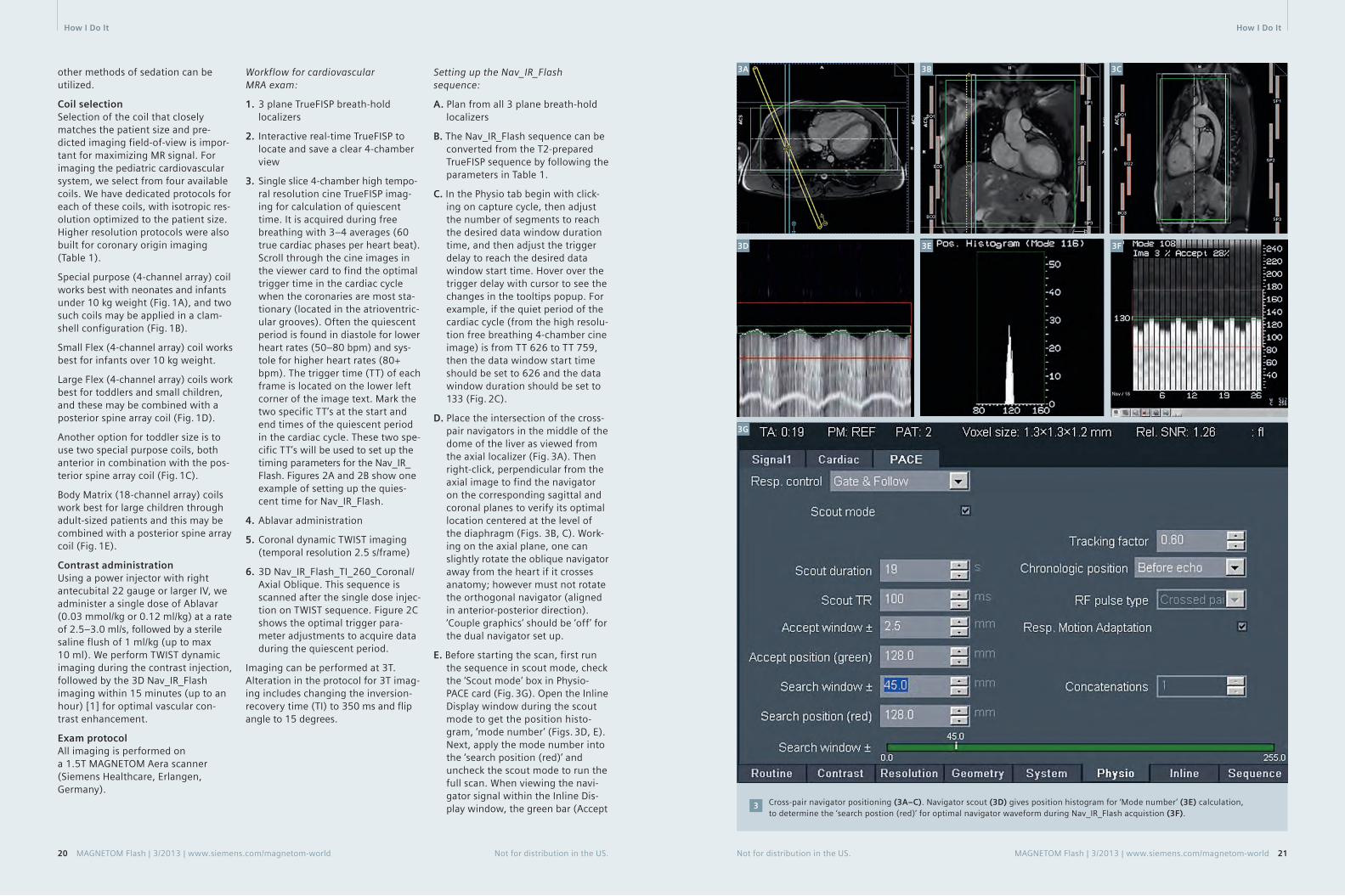
3. Single slice 4-chamber high tempo-ral resolution cine TrueFISP imag-ing for calculation of quiescent time. It is acquired during free breathing with 3–4 averages (60 true cardiac phases per heart beat). Scroll through the cine images in the viewer card to find the optimal trigger time in the cardiac cycle when the coronaries are most sta-tionary (located in the atrioventric-ular grooves). Often the quiescent period is found in diastole for lower heart rates (50–80 bpm) and sys-tole for higher heart rates (80+ bpm). The trigger time (TT) of each frame is located on the lower left corner of the image text. Mark the two specific TT’s at the start and end times of the quiescent period in the cardiac cycle. These two spe-cific TT’s will be used to set up the timing para meters for the Nav_IR_Flash. Figures 2A and 2B show one example of setting up the quies-cent time for Nav_IR_Flash.
4. Ablavar administration
5. Coronal dynamic TWIST imaging (temporal resolution 2.5 s/frame)
6. 3D Nav_IR_Flash_TI_260_Coronal/Axial Oblique. This sequence is scanned after the single dose injec-tion on TWIST sequence. Figure 2C shows the optimal trigger para-meter adjustments to acquire data during the quiescent period.
Imaging can be performed at 3T. Alteration in the protocol for 3T imag-ing includes changing the inversion-recovery time (TI) to 350 ms and flip angle to 15 degrees.
Setting up the Nav_IR_Flash sequence:
A. Plan from all 3 plane breath-hold localizers
B. The Nav_IR_Flash sequence can be converted from the T2-prepared TrueFISP sequence by following the parameters in Table 1.
C. In the Physio tab begin with click-ing on capture cycle, then adjust the number of segments to reach the desired data window duration time, and then adjust the trigger delay to reach the desired data window start time. Hover over the trigger delay with cursor to see the changes in the tooltips popup. For example, if the quiet period of the cardiac cycle (from the high resolu-tion free breathing 4-chamber cine image) is from TT 626 to TT 759, then the data window start time should be set to 626 and the data window duration should be set to 133 (Fig. 2C).
D. Place the intersection of the cross-pair navigators in the middle of the dome of the liver as viewed from the axial localizer (Fig. 3A). Then right-click, perpendicular from the axial image to find the navigator on the corresponding sagittal and coronal planes to verify its optimal location centered at the level of the diaphragm (Figs. 3B, C). Work-ing on the axial plane, one can slightly rotate the oblique navigator away from the heart if it crosses anatomy; however must not rotate the orthogonal navigator (aligned in anterior-posterior direction). ‘Couple graphics’ should be ‘off’ for the dual navigator set up.
E. Before starting the scan, first run the sequence in scout mode, check the ‘Scout mode’ box in Physio- PACE card (Fig. 3G). Open the Inline Display window during the scout mode to get the position histo-gram, ‘mode number’ (Figs. 3D, E). Next, apply the mode number into the ‘search position (red)’ and uncheck the scout mode to run the full scan. When viewing the navi-gator signal within the Inline Dis-play window, the green bar (Accept
Cross-pair navigator positioning (3A–C). Navigator scout (3D) gives position histogram for ‘Mode number’ (3E) calculation, to determine the ‘search postion (red)’ for optimal navigator waveform during Nav_IR_Flash acquistion (3F).
3
3A 3B 3C
3F3D 3E
3G
How I Do It How I Do It
Not for distribution in the US. MAGNETOM Flash | 3/2013 | www.siemens.com/magnetom-world 2120 MAGNETOM Flash | 3/2013 | www.siemens.com/magnetom-world Not for distribution in the US.
Window) should be centered at the end-expiratory peaks of the respi-ratory waveform (Fig. 3F). An acceptance window of ±2.5 mm is typically used with ‘Respiratory Motion Adaption’ selected to ensure that the scan completes even if the patient’s respirations are inconsistent.
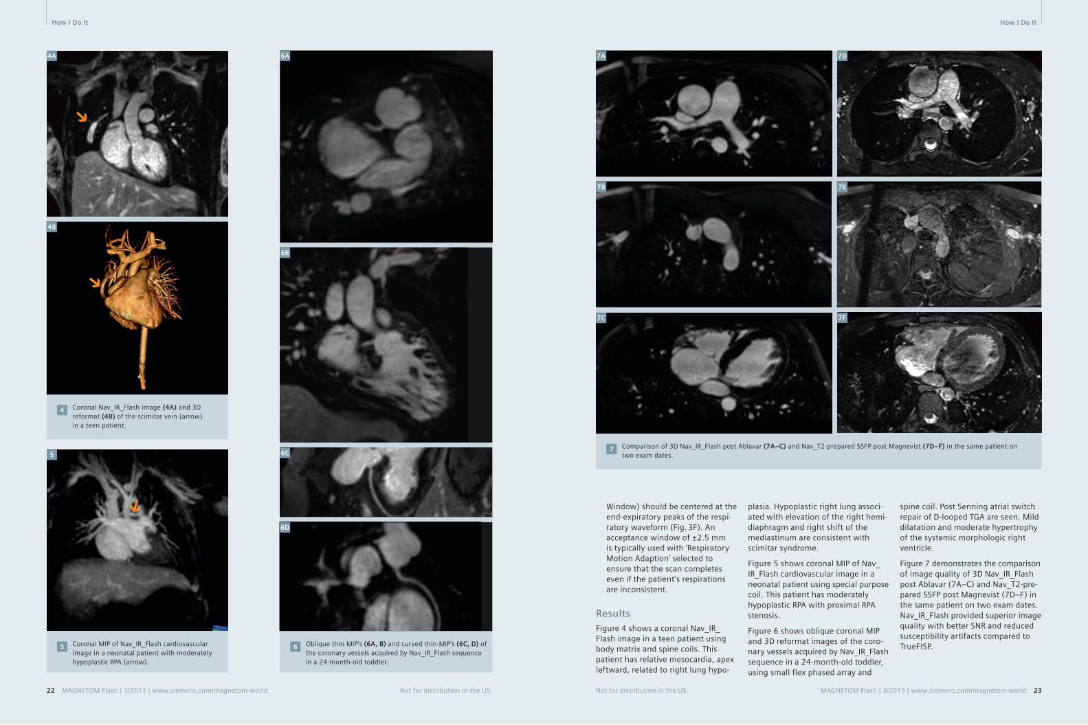
ResultsFigure 4 shows a coronal Nav_IR_Flash image in a teen patient using body matrix and spine coils. This patient has relative mesocardia, apex leftward, related to right lung hypo-
plasia. Hypoplastic right lung associ-ated with elevation of the right hemi-diaphragm and right shift of the mediastinum are consistent with scimitar syndrome.
Figure 5 shows coronal MIP of Nav_IR_Flash cardiovascular image in a neonatal patient using special purpose coil. This patient has moderately hypoplastic RPA with proximal RPA stenosis.
Figure 6 shows oblique coronal MIP and 3D reformat images of the coro-nary vessels acquired by Nav_IR_Flash sequence in a 24-month-old toddler, using small flex phased array and
spine coil. Post Senning atrial switch repair of D-looped TGA are seen. Mild dilatation and moderate hypertrophy of the systemic morphologic right ventricle.
Figure 7 demonstrates the comparison of image quality of 3D Nav_IR_Flash post Ablavar (7A–C) and Nav_T2-pre-pared SSFP post Magnevist (7D–F) in the same patient on two exam dates. Nav_IR_Flash provided superior image quality with better SNR and reduced susceptibility artifacts compared to TrueFISP.
Coronal Nav_IR_Flash image (4A) and 3D reformat (4B) of the scimitar vein (arrow) in a teen patient.
4
4A
Coronal MIP of Nav_IR_Flash cardiovascular image in a neonatal patient with moderately hypoplastic RPA (arrow).
5 Oblique thin-MIP’s (6A, B) and curved thin-MIP’s (6C, D) of the coronary vessels acquired by Nav_IR_Flash sequence in a 24-month-old toddler.
6
Comparison of 3D Nav_IR_Flash post Ablavar (7A–C) and Nav_T2-prepared SSFP post Magnevist (7D–F) in the same patient on two exam dates.
75
4B
6A
6B
7C
7A 7D
7F
7B
6C
6D
7E
Not for distribution in the US. MAGNETOM Flash | 3/2013 | www.siemens.com/magnetom-world 2322 MAGNETOM Flash | 3/2013 | www.siemens.com/magnetom-world Not for distribution in the US.
How I Do It How I Do It

SummaryThe desire for high quality imaging and the goal to minimize radiation doses continues to bring cardiovascu-lar imaging referrals to MRI. The 3D Nav_IR_Flash sequence paired with blood pool contrast agent – gadofos-veset trisodium (Ablavar) are benefi-cial imaging options to evaluate com-plex cardiac indications in pediatric patients.
Acknowledgments We would like to thank the cardio-vascular MRI team at Ann & Robert H. Lurie Children’s Hospital, for their advanced practice and knowledge in implementing this protocol. We would
also like to thank Shivraman Giri, Ph.D., Senior Scientist, Cardiovascular MR R&D Siemens Healthcare, for his help with this article.
Table 1: Resolution parameters for Nav_IR_Flash for large vessels (upper section), for coronary vessels (middle section), and for coil/sequence parameters for all vessels (lower section).
Acquisition parameters Patient size
Large Vessel (Coronal plane) Neonate/Infant ToddlerPediatric/ Small Teen
Large Teen/Adult
FOV (mm × mm × mm)
220 × 165 × 70 280 × 151 × 93 300 × 177 × 123 340 × 204 × 132
Acquired Resolution(mm × mm × mm)
1.1 × 1.1 × 1.5 1.3 × 1.3 × 2.4 1.4 × 1.4 × 2.4 1.5 × 1.5 × 2.5
Reconstructed Resolution (mm × mm × mm)
1.1 × 1.1 × 1.1 1.3 × 1.3 × 1.3 1.4 × 1.4 × 1.4 1.5 × 1.5 × 1.5
Matrix 192 × 192 224 × 224 208 × 208 224 × 208
Coronary(Axial Oblique Plane)
Neonate/Infant ToddlerPediatric/ Small Teen
Large Teen/Adult
FOV(mm × mm × mm)
190 × 190 × 30 250 × 206 × 30 300 × 243 × 40 300 × 243 × 40
Acquired Resolution (mm × mm × mm)
0.9 × 0.9 × 1.32 0.9 × 0.9 × 1.32 0.9 × 0.9 × 1.41 0.9 × 0.9 × 1.67
Reconstructed Resolution(mm × mm × mm)
0.9 × 0.9 × 1.0 0.9 × 0.9 × 1.0 0.9 × 0.9 × 1.0 0.9 × 0.9 × 1.0
Matrix 192 × 192 256 × 256 320 × 320 320 × 320
Coil Special or Small Flex Small or Large FlexLarge Flex or Body Matrix
Body Matrix
TI (Inversion Time) 260 260 260 260
FA (Flip Angle) 18 18 18 18
TE (ms) 1.45 1.39 1.41 1.28
TR (ms) 405 405 405 405
Echo Spacing (ms) 3.45 3.38 3.42 3.18
Contact
Marci Messina, RT(R)(MR)Medical ImagingAnn & Robert H. Lurie Children’s Hospital of Chicago225 E. Chicago Avenue Chicago, Illinois 60611 USA [email protected]
Reference 1 http://www.ablavar.com/mra-agent.html
24 MAGNETOM Flash | 3/2013 | www.siemens.com/magnetom-world Not for distribution in the US.
1. Imaging beyond MRI. Harmonization with syngo.CT Vascular Analysis
2. Fast, semiautomatic lesion measurement. With syngo.MR Vascular Analysis
3. Combine with Angio Dot Engine for optimal angiography workflow from scanning to evaluation
Answers for life.
www.siemens.com/vascular-analysis
Complete Vascular Analysis in less than 15 minutes
0000_Anz_syngo_S4.indd 1 18.07.13 10:22
How I Do It

MR Angiography examinations in our institution are mainly performed in a time-resolved way using the TWIST sequence. The main rationale behind this is to obtain the dynamic informa-tion just like we could obtain using the conventional DSA technique. Indeed, having 4D data sets is of benefit to understanding the impact of stenosing lesions. To date, the only exception to this rule is the imaging of the smaller pudendal vessels in erectile dysfunction. Here we use the Angio Dot Engine to focus on high resolution. All you need to do is plan the sequence, give the resolution and coverage you want and the Dot engine adjusts the delay between injection and scanning to ensure pure arterial phase. You no longer need a pen and paper to calculate that delay.
Figure 1 shows an asymptomatic, mid-dle-aged woman with systolic ‘souffle’ over the right carotid artery inciden-tally noted during physical examina-tion. She has 30 pack years of smok-ing. Inline MIP reconstruction of the 3D data sets (every 6 seconds). Tar-geted reconstructions are performed in post-processing on the desired 3D dataset. The total acquisition time including sequence planning was 5 minutes.
MAGNETOM Aera – Combining Throughput and Highest Quality MR Angiography in an Optimized Clinical WorkflowJohan Dehem, M.D.
VZW Jan Yperman, Ieper, Belgium
We can scan even faster: in breath-hold imaging like thoracic aorta, renal arteries or mesenteric arteries, we like to scan as fast as possible to keep the breath-holds patient-friendly and still have 3D datasets in different
Instant results with Inline MIP of 3D data sets every 6 seconds. Spatial resolution: 0.9 x 0.9 x 0.9 mm isotropic.
1A–E
1A
Targeted MIP reconstructions: (1F) Arterial phase and (1G) late arterial phase 6 seconds later. Both demonstrate the high grade internal carotid artery stenosis.
1F–G
1F 1G
time points providing the dynamic information we want. Figure 2 shows a case of Marfan syndrome. We were asked to exclude ascending aorta aneurysm. Time-resolved imaging in a single breath-hold at 1.2 mm isotro-
2A 2B
pic resolution gives us a 3D dataset every 4 seconds! Targeted MIP and SSD reconstruction on the pure arterial dataset provide excellent detail of the aortic root exluding aneurysm.
2C
1E
1B
1C 1D
Targeted MIP of the aortic root.
2B
SSD reconstruction of the aortic root exluding aneurysm.
2C
Time-resolved imaging in a single breath-hold at 1.2 mm isotropic resolution having a 3D dataset every 4 seconds.
2A
Not for distribution in the US. MAGNETOM Flash | 3/2013 | www.siemens.com/magnetom-world 2726 MAGNETOM Flash | 3/2013 | www.siemens.com/magnetom-world Not for distribution in the US.
Clinical MR Angiography MR Angiography Clinical

Figure 3 shows images of an 81-year-old female patient in poor condition presenting with angor abdominalis. We were asked to exclude mesenteric artery stenosis. Time-resolved imag-ing without breath-hold command (cooperation was non-existant) with a 3D dataset every 3 seconds already depicting a renal artery stenosis on the coronal overview images and nicely depicting high-grade stenosis on the sagittal overview series and on the targeted thin MIP of the pure arterial series.
3A
3B 3D dataset every 3 seconds, depicting a renal artery stenosis in this case of angor abdominalis.
3A
4A
4B
4C
We perform imaging of the aorta and lower and upper leg arteries in a time-resolved way to pick up the dynamic physiologic information regarding the peripheral run off. We start the examination on the lower legs having 3D series every 5 seconds in a 1.1 mm isotropic resolution using 5 cc or less of 1M gadolinium contrast followed by 30 cc saline flush (Fig. 4A), we repeat that sequence for the upper legs with 6 cc gd and saline flush (Fig. 4B); and complete this with a time-resolved series of the abdomen in 1.2 mm isotropic resolution.
The pure arterial phases are com-posed and rendered in 3D (Fig. 4C) giving the vascular surgeons their roadmap to intervene and the dynamic series to have a full diagnostic skill set with physiologic information. As a bonus since you scan dyna-mically venous contamination is no longer an issue.
High temporal resolution in dynamic imaging can be the ultimate trick to
Arterial phase targeted thin MIP coronal and sagittal at 81 seconds, showing renal artery stenosis.
3B
Lower legs 3D series every 5 seconds.4A
Upper legs 3D series in 5 seconds.4B
Composed aorta, lower and upper leg arterial phases provide a 3D roadmap for vascular surgeons.
4C
Not for distribution in the US. MAGNETOM Flash | 3/2013 | www.siemens.com/magnetom-world 2928 MAGNETOM Flash | 3/2013 | www.siemens.com/magnetom-world Not for distribution in the US.
Clinical MR Angiography MR Angiography Clinical

image organs with a fast venous retour like the kidneys, but also for the hand.
Figure 5 show targeted reconstruction images in a case of Buerger’s disease in pure arterial phase (5A) and time-resolved overview images of a male patient with repetitive strain injury (RSI) due to drilling occupation, the small arteries of the hand and fingers are readily depicted and occlusions are readily depicted. The two 3D datasets in figure 5B have been obtained in less than 2 seconds!
MR angiogram (MRA) of the pudendal artery: high resolution is really key in this examination since we are look-ing for small vessels. If the surgeon wants to perform a bypass, we want to know if distal outflow is present, so good arterial timing is the other key issue. However, to obtain this spatial resolution and coverage in a time-resolved fashion is not satisfying, which is why the testbolus technique is still preferred in this clinical setting.
Whereas testbolus MRA could be tricky in the past (having a piece of paper at hand to calculate your delay),
Targeted MIP reconstruction in a case of Buerger’s disease. Spatial resolution 0.7 mm isotropic, using the 16-channel hand-wrist coil.
5A
Screenshot showing the advantage of the Angio Dot Engine in calculating the delay.6
Overview thick MIP showing excellent image quality.7
the Angio Dot Engine effectively calculates and updates the delay depending on the planned coverage / resolution (Fig. 6). The operator only has to place the region-of-interest (ROI) in the artery and vein of the testbolus image. This is easy, very robust, ultimately foolproof! Starting your contrast injection and starting your sequence at the same time gives you a pop-up-window with a count-down of the delay time until the arte-rial phase effectively starts. Subtrac-tion is performed inline.
The resulting image quality of the 3D subtracted data set provides the signal and detail you need to recon-struct the angiographic images as depicted in figure 7.
Contact
Johan Dehem, M.D. VZW Jan Yperman Ieper Belgium [email protected]
Targeted reconstruction of pudendal artery demonstrating severe narrowing and irregularities but patent distal outflow.
8
5A 5B
6
7A
7B
8A 8B
A case of RSI due to drilling activity. MIP of the 3D dataset at timepoint 32.5 s and at timpoint 34 s: 1.5 seconds apart!
5BFurther InformationVisit us at www.siemens.com/magentom-world to listen to Dr. Dehemʼs talk on Highest Quality Imaging in an Optimized Clinical Workflow given during the lunch symposium at the 15th International MRI Symposium 2013 in Garmisch-Partenkirchen, Germany
Go to www.siemens.com/magnetom-word > Clinical Corner > Clinical Talks
Johan Dehem, M.D. VZW Jan Yperman (leper, Belgium)
Not for distribution in the US. MAGNETOM Flash | 3/2013 | www.siemens.com/magnetom-world 3130 MAGNETOM Flash | 3/2013 | www.siemens.com/magnetom-world Not for distribution in the US.
Clinical MR Angiography MR Angiography Clinical

Not for distribution in the US. MAGNETOM Flash | 3/2013 | www.siemens.com/magnetom-world 33
of the acquisition. Furthermore, the conventional gated CE-MRA technique cannot reduce scan time by taking advantage of parallel acquisition tech-nique (iPAT) and partial Fourier in phase encoding direction; if either of these parameters is modified, the total scan time remains the same since conventional CE-MRA only a single complete inner loop is played out per heartbeat, regardless of its duration.
Moreover, the unpredictable nature of the ECG-triggering adds some uncertainty to the gated CE-MRA method. While the sequence assumes a steady R-R interval and uses a fixed acquisition window, due to physiolog-ical irregularities (the R-R interval can vary during a breath-hold [5]) and mechanical imperfections (ECG detec-tion device can fail), trigger events
can be either detected too early or too late to substantially increase the scan time. The CE-MRA sequence has a strict timing requirement with the contrast arrival, and any deviation from this may result in a contrast washout with missed optimal timing.
This paper highlights recent advance-ments in the ECG-gated CE-MRA approach* that address these short-comings. With these advancements, high-resolution, full coverage ECG-gated CE-MRA exams can be realized within a single breath-hold.
* The sequence is currently under develop-ment and is available as a work-in-progress package (#691B for VB17A and #791 for VD11D/13A); it is not for the sale in the US and other countries. Its future availability cannot be guaranteed.
Flexible trigger segmentationTo improve the efficiency of the rigid trigger segmentation in conventional gated CE-MRA, we propose a flexible approach (Fig. 3). Here, the inner loop is not restricted to a single dimen-sion in k-space. The points that are sampled within the individual triggered segments are determined with a fuzzy pseudo-random algorithm. As a result, the size and shape of the triggered segments are no longer restricted. In addition, the flexible triggered segmentation can freely adjust the acquisition order, both within and in between triggered segments.
The conventional approach to ECG-gated CE-MRA. In each heartbeat, all phase-encoding steps of a single slice-encoding line are acquired. The TTC can be matched with the contrast timing since each triggered shot is acquired in linear order in slice direction.
2
Heart Beat #
1
2
⋅
⋅
⋅
Outer Loop (Slice-Enc.,kz)
Inner Loop (Phase-Enc., ky)
Arterial w
ind
ow
Time
arterial phase
venous phase
ECG
Trigger Delay
Inner Loop 1Wait Time
Trigger Delay
Inner Loop 2Wait Time
Heart Beat #1 Heart Beat #2
• • •
2
Non-gated CE-MRA vs. gated CE-MRA. Darker purple color bar represents the outer k-space in both phase (ky) and slice (kz) encoding steps, and the lighter purple repre-sents the inner k-space. The center of both phase and slice encoding steps (ky=0, kz=0) is represented by k=0. Typically in CE-MRA, the contrast arrival timing is matched with the center acquisition of the phase and slice encoding steps (i.e. considering the time-to-center, TTC) for the optimal image contrast. For non-gated CE-MRA, the data is acquired in a single continuous delayed centric trajectory, where phase and slice encoding steps start from the outer k-space, then acquire inner k-space & k=0, and finally the rest of the outerk-space to complete the scan. For the gated CE-MRA, the acquisition is segmented (e.g. Fig. 2) and acquired in sync with the ECG-triggering.
1
Advancements in the ECG-Gated Contrast-Enhanced MR AngiographyYutaka Natsuaki, Ph.D.1; Randall Kroeker, Ph.D.1; Gerhard Laub, Ph.D.1; Peter Schmitt2; J. Paul Finn, M.D.3
1 Siemens Healthcare, CA, USA 2 Siemens AG, Healthcare Sector, Imaging & Therapy Division, Erlangen, Germany 3 Diagnostic Cardiovascular Imaging, Department of Radiology, David Geffen School of Medicine at UCLA, CA, USA
32 MAGNETOM Flash | 3/2013 | www.siemens.com/magnetom-world Not for distribution in the US.
IntroductionFor most of the current contrast-enhanced MR angiography (CE-MRA) examinations, the acquisition is optimized for the image contrast enhancement by matching the con-trast arrival timing with the acquisi-tion of the central phase encoding steps (i.e. time-to-center, TTC) [1]. The total scan time is kept short within a breath-hold length (less than 25 s) to suppress bulk breathing motion. Typically, the CE-MRA data are acquired without ECG-gating in a single contin-uous delayed centric trajectory (Fig. 1, non-gated CE-MRA). While, for most purposes, this approach is entirely satisfactory, in CE-MRA of the thorax the cardiac chambers and ventricular outflow vessels can be delineated with a certain degree of blurring with non-gated acquisition. To address this limitation, CE-MRA can be acquired with ECG gating, whereby the seg-mented data acquisition is synchro-nized with the cardiac cycle [2, 3, 4] (Fig. 1, gated CE-MRA).
The current product version of the CE-MRA sequence (fl3d_ce) supports ECG gating with a rigid trigger seg-mentation (Fig. 2, conventional gated CE-MRA). For every trigger pulse, the conventional gated CE-MRA acquires all phase encoding steps for a single value of the slice encoding gradient. The acquisition is then repeated in linear order for all slice encoding val-ues. With a suitable trigger delay (TD), the center of k-space in the inner loop (i.e. phase-encoding) direction (ky = 0) can be acquired outside of the sys-
tolic phase, where the cardiac motions are most prominent. With proper contrast injection timing, the arterial window can still be matched with the center of the k-space in the outer loop (i.e. slice encoding) direction. With this scheme, the total scan time corresponds to the average R-R inter-val multiplied by the total number of slice encoding steps.
1
ECG
Non-Gated CE-MRA
Gated CE-MRA
Time To Center (TTC)
Time To Center (TTC)
k=0
k=0
The major drawback of this conven-tional gated CE-MRA approach is its acquisition inefficiency. A typical high-resolution non-gated CE-MRA proto-col uses short TR times of 2.7 ms and less than 200 phase encode steps in ky direction. Hence, the data acquisi-tion window during each heartbeat is much shorter than the average R-R interval, which reduces the efficiency
k
k
Technology MR Angiography MR Angiography Technology

The conventional gated CE-MRA with rigid triggered segmentation vs. the proposed gated CE-MRA with flexible triggered segmen-tation. The flexible triggered segmentation can fill in any unnecessary wait time after the data acquisition window (seq. acq.), and thus more efficient. Note that even with the proposed flexible triggered segmentation, the total efficiency is around 70% due to the trigger delay needed for avoiding cardiac motion during systolic phase. Furthermore the center of the triggered segments can be specified with the flexible triggered segments, while the rigid triggered segments case will be fixed somewhere in the middle of the acquisition window.
3
34 MAGNETOM Flash | 3/2013 | www.siemens.com/magnetom-world Not for distribution in the US.
are positioned in diastole (i.e. the quiescent phase with the minimal cardiac motion). With the proposed sequence, the time used for each individual triggered segment acquisi-tion has been increased in order to use the RR interval more efficiently. In order to achieve this, we need a flexible reordering that (1) assigns more k-space points to each triggered segments, and (2) makes sure that the most important data points within each shot (lines close to k-space cen-ter, kz=0 in Fig.3) are still acquired in diastole. In the proposed sequence, the linear-centric reordering (e.g. combination of linear and centric reor-dering, with simple example shown in Fig.4) enables this regardless of the size and the shape of the triggered segments. The user interface para-meter ‘Time-To-Center (TTC) per Heart
Scan efficiency improvements with flexible triggered segmentations With a flexible size of the triggered shots, the sequence can utilize essen-tially all of the available time in the acquisition window, which helps reduce unnecessary wait time. In practice, this alone can improve the scan efficiency of a gated CE-MRA acquisition to values close to 70%, which is more than twice the conven-tional gated CE-MRA of approx. 30%. Furthermore, the flexible segmenta-tion is compatible with conventional scan time reduction methods such as iPAT, partial Fourier, and elliptical scanning.
The rigid trigger segmentation can potentially improve the scan effi-ciency by acquiring multiple complete phase encoding lines since each trig-
ger segment acquisition is typically far shorter than the RR interval (as shown in Fig.3). This, however, is still restricted since the in-vivo RR interval can never match to the exact integer multiples of the complete phase encoding lines. Also the scan effi-ciency varies according to the actual heart rates, and on shorter extreme of the RR interval the gated CE-MRA cannot be performed.
Cardiac motion suppression with flexible center of the triggered segmentations In the conventional gated CE-MRA, only the PE steps for a single partition encoding step are acquired. This corresponds to the comparatively short acquisition duration. In order to reduce the pulsatile cardiac motion, these triggered segment acquisitions
3
Not for distribution in the US. MAGNETOM Flash | 3/2013 | www.siemens.com/magnetom-world 35
Schematic diagram of the flexible inter-triggered shot ordering. Each triggered shot is represented by the different color on the ky-kz map (right), and has assigned ShotPos# in linear ascending order. The figure on the left represents the overall triggered shot acquisition timing relative to the contrast injection. The overall TTC is defined as the time from the beginning of the scan to the acquisition of the center positioned segment (in above example, SegPos#3).
4
MR Angiography Technology
Conventional gated CE-MRA Proposed gated CE-MRA
ECG
Trigger Delay
Wait Time
Acquisition Window
Fixed ky = 0
ECG
Trigger Delay
No Wait Time
Flexible kz = 0
Acquisition Window
Seg. Acq.
Triggered Segmentation
Center of the Segment
kz (Slice-Enc., Outer Loop) kz (Slice-Enc., Inner Loop)
ky
(Phase-Enc., Outer Loop)
ky
(Phase-Enc., Inner Loop)
Flexible Triggered Segmentation
kz
ky
1 2 3 4 5Seg Pos. #
Arterial window
arterial phase
venous phase
SegPos #3 SegPos #2 SegPos #4 SegPos #1 SegPos #5
SegPos #2 SegPos #3 SegPos #4 SegPos #1 SegPos #5
SegPos #1 SegPos #2 SegPos #3 SegPos #4 SegPos #5
SegPos #1 SegPos #4 SegPos #2 SegPos #3 SegPos #5
HB# with TTC
1 (centric out)
2 (linear-centric)
3 (linear ascend)
4 (centric in)
Time
Scan Window (fixed)
Trigger Delay (TD)Wait for the next Trigger Event
Acquisition Window
ECG
Dummy Data Acquisition Dummy
4
5
Beat (HB)’ (located on the Sequence Special Card) is utilized to specify the center of the triggered segment acquisition timing, and this can be set to anywhere within the acquisition window.
Contrast timing optimization with flexible triggered segments reordering The order of the inter trigger shots is also flexible in the proposed approach. With the linear-centric algorithm, the user can specify when to acquire the triggered shot that encompasses the k-space center (ky = 0, kz = 0, Shot-Pos#3 in the example in Fig.4). In analogy to the ‘TTC’ parameter in the non-gated CE-MRA, the user interface parameter ‘overall TTC’ calculates and adjusts the triggered shot ordering to the closest match.
User interface (UI) improvements From user perspective, the flexible triggered segmentation in the pro-posed gated CE-MRA translates into an intuitive UI experience: For TTC per HB, for the specific cardiac phase timing only one additional UI parame-ter was required. Other than captur-ing the cardiac cycle and setting few parameters (trigger delay and TTC per HB), all the other protocol parameters
Steady state triggering. In order to maintain the magnetization in FLASH readout (represented as green dots), the steady state triggering continues to play out RF pulses without data acquisition during the wait time and trigger delay (i.e. Dummy pulses, represented as black dots).
5
can remain the same as for a standard non-gated CE-MRA protocol. Unlike the conventional gated CE-MRA where other scan parameters such as matrix size, resolution, FOV and PAT factor determine the segmentation, and particularly the duration of a sin-gle shot. In the proposed CE-MRA, however, shot duration is automati-cally adjusted according to the sub-ject’s heartbeat.
Adaptive steady state triggeringThe proposed gated CE-MRA has implemented the steady state trigger-ing mechanism (i.e. RF pulses are played out without acquisition during the wait time and the trigger delay) in order to avoid signal variations in the segmented FLASH readout (Fig.5). In addition, the proposed gated CE-MRA
Seg. Acq.
Technology MR Angiography

automatically adapts the steady state triggering to compensate some of the commonly occurring trigger issues (i.e. early and late trigger detections). This adaptive steady state triggering ensures that the gated CE-MRA is completed in an efficient manner.
Early trigger cases In the conventional approach, any trigger event that occurs within the acquisition window of the preceding shot is not detected. There are many cases where the R-R interval has been shortened just enough to miss the trigger event (i. e. the early trigger event). The goal of the adaptive approach is to salvage the early trig-
(= 130% of R-R interval) has elapsed, the trigger event is enforced with TD = 0. If we observe the 2 consecu-tive maximum wait times (i.e. 4 total heart beats without an event), shorten the maximum wait time to 30% of R-R interval in order to complete the scan within the reasonable time.
Results and feedbackThe proposed gated CE-MRA sequence has been tested on both 1.5T and 3T scanners at multiple research collaboration sites. The feedback is overwhelmingly positive thus far.
Segment AcquisitionDelay
Segment AcquisitionDelay Segment Acquisition Delay S.Adj.
Delay S.
Missed Trigger
Missed Trigger
Resume Here
Skip Acquisition
Resume Acquisition as usual
Adjust Delay
Conventional Triggering
Adaptive Triggering
6
Schematic diagram of the early trigger case (missed trigger event). In the conventional case, any missed trigger will result in an unused RR interval. The adaptive triggering, on the other hand, will adjust the delay time to compensate the missed trigger time if it is less than the trigger delay.
6
Triggered Segment Acq. #1
Max Wait Time (Ave RR x 130%)
Forced Segment Acq. #3
Max Wait Time (Ave RR x 130%)
Forced Segment Acq. #3
Red. Max Wait Time
Forced Segment Acq. #4
Heart Beats #1 (RR interval)
Heart Beats #2 (RR interval)
Heart Beats #3 (RR interval)
Heart Beats #4 (RR interval)
Reduced Max Wait Time (Ave RR x 30%)
7
Schematic diagram of the late trigger case. When the maximal wait time occurs consecutively, which corresponds to the equiv-alent time of 4 RR intervals, and it is assumed that the ECG has failed. In anticipation of further delays, the maximum duration will be reduced for the remaining scan time to ensure the completion of the scan. If the ECG recovers, the sequence can revert to the regular trigger detection mode, but with reduced maximal wait time.
7
ger event as much as possible and retain the original TD from the trigger event. Once the scan window is com-pleted, the algorithm checks when the trigger event has occurred during the segment acquisition and then calculates the Missed Trigger Time (= the delay time since the latest trig-ger event). If a trigger event is detected during the acquisition, the TD of the next shot will be reduced accordingly.
Late trigger cases In order to complete the gated CE-MRA in the case of an ECG trigger failure, it is important to enforce a trigger event after a pre-determined maximum wait time. After a maximum wait time
Non-Gated CE-MRA (21 s, 100% efficiency)8 New Gated CE-MRA (21 s, 75% efficiency)
Direct comparison of the non-gated vs. gated CE-MRA on the same healthy volunteer. Reformatted thinMIPs of coronal (native acquisition orientation), sagittal and axial orientations are shown. The acquisition parameters are identical, except the gated CE-MRA has few additional parameters in TTC per HB, Acquisition window, and trigger delay. Also the gated CE-MRA has acquired with the elliptical scan to help compensate the efficiency loss.
Imaging details: 1.5T MAGNETOM Avanto (software version syngo MR B17A), 6-channel body matrix coil + spine coil, 3D FLASH (fl3d_ce) readout, coronal orientation, GRAPPA with integrated reference scans, iPAT acceleration factor 3, FOV 375 × 500 mm2, matrix 288 × 512, voxel size 1.3 × 1.0 ×1.3 mm3, 120 slices (67 slice encoding steps with partial Fourier 6/8 and slice res. 66%), TTC 6 s, total scan time 21 s. For the gated CE-MRA only: TD 150 ms, TTC per HB set at quiescent mid diastole.
8
9C
Various clinical results with the proposed gated CE-MRA as obtained on a 1.5T MAGNETOM Avanto. All images are reformatted thin MIPs based on the original coronal acquisition data. (9A) Left arterial descending coronary artery. (9B) Stent lumen narrowing, post repair of aortic coarctation. (9C) Dilation of ascending aorta due to aneurism. (9D) Aortic dissection.
Imaging parameters are identical to those provided with figure 8.
9
9A 9B 9D
Data Acquisition
Technology MR Angiography
Not for distribution in the US. MAGNETOM Flash | 3/2013 | www.siemens.com/magnetom-world 37 36 MAGNETOM Flash | 3/2013 | www.siemens.com/magnetom-world Not for distribution in the US.

Contact
Yutaka NatsuakiSiemens Medical Solutions USA, Inc.NAM RC-US H IM MR COL10945 Le Conte Avenue, Suite 337190095 Los Angeles, CA [email protected]
References 1 Prince MR, Grist TM, and Debatin JF.
3D Contrast MR Angiography. Berlin: Springer, 2003.
2 Simonetti OP, Finn JP, R.D.W, Bis KG, Shetty AN, Tkach J, Flamm SD, and Laub G. Proc.ISMRM 1996.
3 Spincemaille P, Zhao XH, Cheng L, Prince M, and Wang Y. Proc.IEEE EMBS 2006.
4 Ashman R, Hull E. Essentials of electrocar-diography for the student and practi-tioner of medicine, 2nd ed. New York: Macmillan; 1945. p162–163.
5 Natsuaki Y, Kroeker R, Finn JP, Schmitt P, and Laub G. Proc ISMRM 2013.
In clinical practice, cardiothoracic CE-MRA is typically acquired without ECG gating, with high resolution and within a single breath-hold (e.g. cor-onal orientation to cover the whole chest, image matrix 288 × 512 (phase × read), slices 120, slice reso-lution 66%, partial Fourier 6/8 (corre-sponding to 67 partition encoding
steps), GRAPPA with iPAT factor 3, and voxel size 1.3 × 1.0 × 1.3 mm3, total scan time 21 s). With the con-ventional gated CE-MRA, the same resolution is impossible to achieve within a breath-hold; the correspond-ing protocol would either take too long (in the example above, 67 heart beats, or 50–60 seconds) or would
A clinical result with the proposed gated CE-MRA obtained on a 3T MAGNETOM Trio with Tim. 12-year-old patient with congenital heart disease (CHD) vascular ring case with 1st pass gated CE-MRA. The image was acquired in an anesthetized pediatric patient who could perform ‘perfect’ breath-holds. (10A) Coronal thin MIP of the original data. (10B) Volume-rendered reconstruction of the gated CE-MRA in coronal view. (10C) Volume-rendered reconstruction, zoomed in at the vascular region. (10D) Volume-rendered recon-struction, zoomed in and rotated for visualizing the vascular ring.
Imaging parameters: 3T MAGNETOM Trio, a Tim system (software version syngo MR B17A), 6-channel body matrix coil + spine coil, 3D FLASH (fl3d_ce) readout, coronal orientation, GRAPPA with integrated reference scans, iPAT acceleration factor 4, FOV 312 × 500 mm2, matrix 285 x 608, voxel size 1.1 x 0.8 x 1 mm3, 120 slices (67 slice encoding steps with partial Fourier 6/8 and slice res. 66%), TR 2.86 ms, TE 1.04 ms, TTC 6 s, TD 50 ms, TTC per HB at quiescent mid diastole, total scan time 20 s.
10
be limited with respect to its coverage in slice direction (with a maximum breath-hold duration of approx. 25 s, the conventional gated CE-MRA only allows about 25–30 slice encoding steps).
The proposed gated CE-MRA with flexi-ble triggered segments, however,
10C matches the typical non-gated cardio-thoracic CE-MRA protocols in both resolution and coverage, all within a slight increase in breath-hold (typically 1-2 seconds or less). Despite the scan efficiency improvements, the proposed sequence still has ~70% efficiency compared to the 100% efficiency of the non-gated counterpart. The ~30% efficiency loss in the gated CE-MRA has been mostly compensated by the elliptical scan and slightly less slice oversampling (and thus able to mini-mize an extra breath-hold to be in 1-2 seconds or less). The pulsatile car-diac motion artifacts of the ECG-gating is evident when the sequences are directly compared on the same volun-teer with identical scan parameters and contrast injection profile (Fig. 8). Many clinical study cases have shown improved vascular image quality that would not be possible without ECG gating (Figs. 9, 10).
The adaptive steady state feature increases confidence in the use if gated CE-MRA technique instead of a clinical standard non-gated CE-MRA. Among the feedback cases, early trigger events were detected occasionally (about 10% of the feedback study cases have shown slight shortening of the R-R interval). All of these early trigger cases were completed within a single breath-hold (slightly shorter than predicted total scan time), and none of them had shown adverse effects such as washed out contrast or excessive motion arti-facts. No feedback cases had shown late triggering, i.e. the ECG-triggering did not fail in any of these cases, and the R-R interval change (extension) was never significant enough to enforce a trigger event.
ConclusionThe conventional ECG-gated CE-MRA has been available for more than a decade. While the benefits of ECG-gated CE-MRA in the cardiac pulsatile motion reduction are well documented, the technique has remained a niche application, mainly due to its low scan efficiency (only about 30%) and its limited slice coverage (only 25-30 slice partitions within a breath-hold). In addition, physiological and mechanical imper-fections of the ECG-triggering might have led to reduced user confidence. The overall robustness of non-gated CE-MRA might have out weighted the benefit of the gated CE-MRA, so that the mainstream cardiothoracic CE-MRA had been acquired without ECG.
The proposed gated CE-MRA addresses these major drawbacks of the con-ventional gated CE-MRA. With the flex-ible trigger segmentation, the pro-posed gated CE-MRA now provides vastly improved scan efficiency (about 70% or above) and is no longer restricted in terms of slice coverage. The adaptive steady state triggering ensures a CE-MRA scan completion in a very efficient manner, and further improves the robustness of the sequence. The proposed gated CE-MRA has high potential as a viable option for high-resolution cardiothoracic CE-MRA. Further clinical research col-laborations and tests are warranted.
AcknowledgmentsThe authors thank Siemens Health-care colleagues for their continuous support and contributions, especially to Xiaoming Bi, Vibhas Deshpande, Marcel Dominik Nickel, Shivraman Giri, Kevin Johnson, and Gary McNeal.
10A 10B
10D
MR Angiography TechnologyTechnology MR Angiography
Not for distribution in the US. MAGNETOM Flash | 3/2013 | www.siemens.com/magnetom-world 39 38 MAGNETOM Flash | 3/2013 | www.siemens.com/magnetom-world Not for distribution in the US.
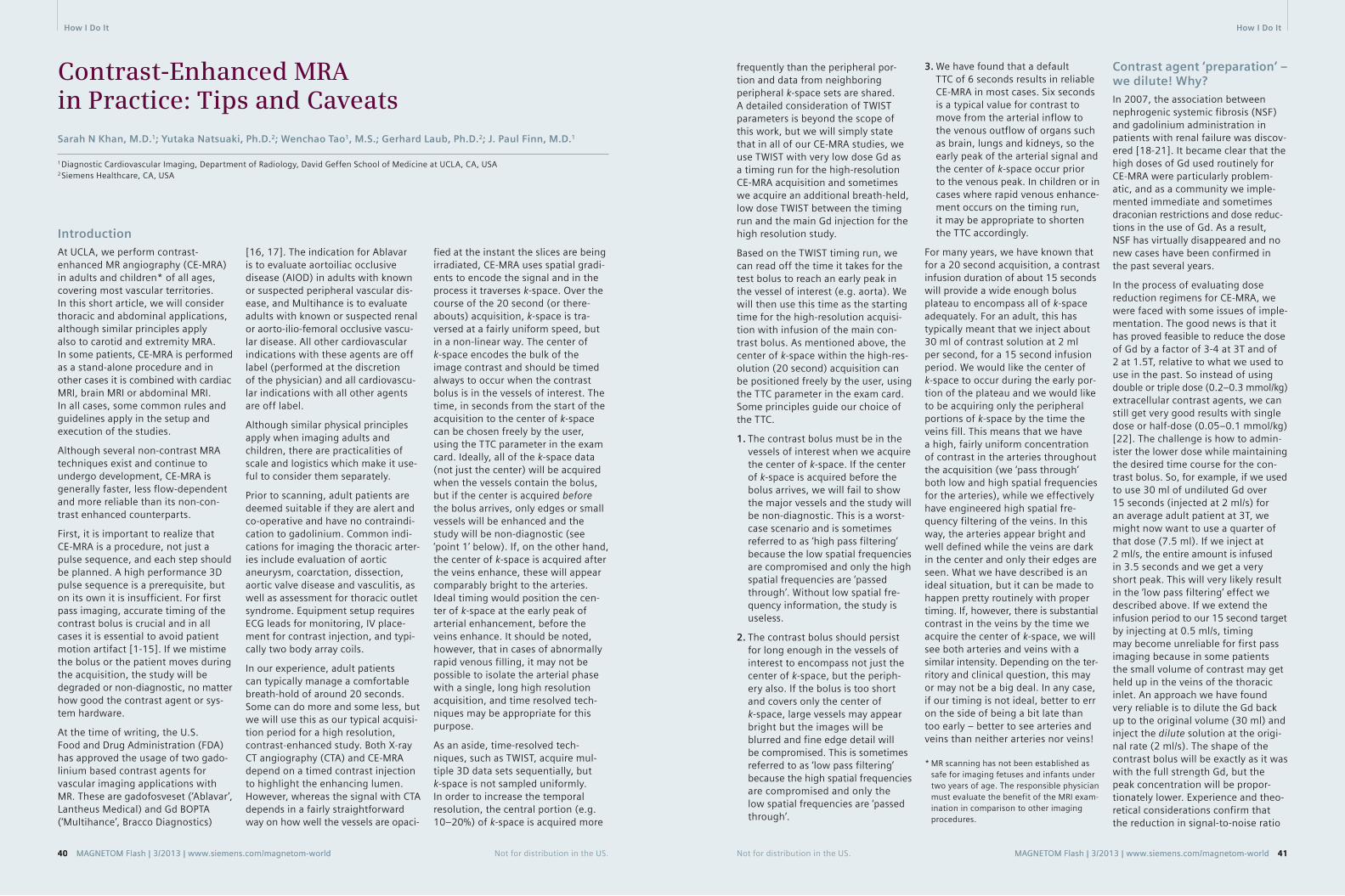
MAGNETOM Flash | 3/2013 | www.siemens.com/magnetom-world 4140 MAGNETOM Flash | 3/2013 | www.siemens.com/magnetom-world
How I Do It How I Do It
IntroductionAt UCLA, we perform contrast-enhanced MR angiography (CE-MRA) in adults and children* of all ages, covering most vascular territories. In this short article, we will consider thoracic and abdominal applications, although similar principles apply also to carotid and extremity MRA. In some patients, CE-MRA is performed as a stand-alone procedure and in other cases it is combined with cardiac MRI, brain MRI or abdominal MRI. In all cases, some common rules and guidelines apply in the setup and execution of the studies.
Although several non-contrast MRA techniques exist and continue to undergo development, CE-MRA is generally faster, less flow-dependent and more reliable than its non-con-trast enhanced counterparts.
First, it is important to realize that CE-MRA is a procedure, not just a pulse sequence, and each step should be planned. A high performance 3D pulse sequence is a prerequisite, but on its own it is insufficient. For first pass imaging, accurate timing of the contrast bolus is crucial and in all cases it is essential to avoid patient motion artifact [1-15]. If we mistime the bolus or the patient moves during the acquisition, the study will be degraded or non-diagnostic, no matter how good the contrast agent or sys-tem hardware.
At the time of writing, the U.S. Food and Drug Administration (FDA) has approved the usage of two gado-linium based contrast agents for vascular imaging applications with MR. These are gadofosveset (‘Ablavar’, Lantheus Medical) and Gd BOPTA (‘Multihance’, Bracco Diagnostics)
Contrast-Enhanced MRA in Practice: Tips and CaveatsSarah N Khan, M.D.1; Yutaka Natsuaki, Ph.D.2; Wenchao Tao1, M.S.; Gerhard Laub, Ph.D.2; J. Paul Finn, M.D.1
1 Diagnostic Cardiovascular Imaging, Department of Radiology, David Geffen School of Medicine at UCLA, CA, USA 2 Siemens Healthcare, CA, USA
frequently than the peripheral por-tion and data from neighboring peripheral k-space sets are shared. A detailed consideration of TWIST parameters is beyond the scope of this work, but we will simply state that in all of our CE-MRA studies, we use TWIST with very low dose Gd as a timing run for the high-resolution CE-MRA acquisition and sometimes we acquire an additional breath-held, low dose TWIST between the timing run and the main Gd injection for the high resolution study.
Based on the TWIST timing run, we can read off the time it takes for the test bolus to reach an early peak in the vessel of interest (e.g. aorta). We will then use this time as the starting time for the high-resolution acquisi-tion with infusion of the main con-trast bolus. As mentioned above, the center of k-space within the high-res-olution (20 second) acquisition can be positioned freely by the user, using the TTC parameter in the exam card. Some principles guide our choice of the TTC.
1. The contrast bolus must be in the vessels of interest when we acquire the center of k-space. If the center of k-space is acquired before the bolus arrives, we will fail to show the major vessels and the study will be non-diagnostic. This is a worst-case scenario and is sometimes referred to as ‘high pass filtering’ because the low spatial frequencies are compromised and only the high spatial frequencies are ‘passed through’. Without low spatial fre-quency information, the study is useless.
2. The contrast bolus should persist for long enough in the vessels of interest to encompass not just the center of k-space, but the periph-ery also. If the bolus is too short and covers only the center of k-space, large vessels may appear bright but the images will be blurred and fine edge detail will be compromised. This is sometimes referred to as ‘low pass filtering’ because the high spatial frequencies are compromised and only the low spatial frequencies are ‘passed through’.
Contrast agent ‘preparation’ – we dilute! Why?In 2007, the association between nephrogenic systemic fibrosis (NSF) and gadolinium administration in patients with renal failure was discov-ered [18-21]. It became clear that the high doses of Gd used routinely for CE-MRA were particularly problem-atic, and as a community we imple-mented immediate and sometimes draconian restrictions and dose reduc-tions in the use of Gd. As a result, NSF has virtually disappeared and no new cases have been confirmed in the past several years.
In the process of evaluating dose reduction regimens for CE-MRA, we were faced with some issues of imple-mentation. The good news is that it has proved feasible to reduce the dose of Gd by a factor of 3-4 at 3T and of 2 at 1.5T, relative to what we used to use in the past. So instead of using double or triple dose (0.2–0.3 mmol/kg) extracellular contrast agents, we can still get very good results with single dose or half-dose (0.05–0.1 mmol/kg) [22]. The challenge is how to admin-ister the lower dose while maintaining the desired time course for the con-trast bolus. So, for example, if we used to use 30 ml of undiluted Gd over 15 seconds (injected at 2 ml/s) for an average adult patient at 3T, we might now want to use a quarter of that dose (7.5 ml). If we inject at 2 ml/s, the entire amount is infused in 3.5 seconds and we get a very short peak. This will very likely result in the ‘low pass filtering’ effect we described above. If we extend the infusion period to our 15 second target by injecting at 0.5 ml/s, timing may become unreliable for first pass imaging because in some patients the small volume of contrast may get held up in the veins of the thoracic inlet. An approach we have found very reliable is to dilute the Gd back up to the original volume (30 ml) and inject the dilute solution at the origi-nal rate (2 ml/s). The shape of the contrast bolus will be exactly as it was with the full strength Gd, but the peak concentration will be propor-tionately lower. Experience and theo-retical considerations confirm that the reduction in signal-to-noise ratio
3. We have found that a default TTC of 6 seconds results in reliable CE-MRA in most cases. Six seconds is a typical value for contrast to move from the arterial inflow to the venous outflow of organs such as brain, lungs and kidneys, so the early peak of the arterial signal and the center of k-space occur prior to the venous peak. In children or in cases where rapid venous enhance-ment occurs on the timing run, it may be appropriate to shorten the TTC accordingly.
For many years, we have known that for a 20 second acquisition, a contrast infusion duration of about 15 seconds will provide a wide enough bolus plateau to encompass all of k-space adequately. For an adult, this has typically meant that we inject about 30 ml of contrast solution at 2 ml per second, for a 15 second infusion period. We would like the center of k-space to occur during the early por-tion of the plateau and we would like to be acquiring only the peripheral portions of k-space by the time the veins fill. This means that we have a high, fairly uniform concentration of contrast in the arteries throughout the acquisition (we ‘pass through’ both low and high spatial frequencies for the arteries), while we effectively have engineered high spatial fre-quency filtering of the veins. In this way, the arteries appear bright and well defined while the veins are dark in the center and only their edges are seen. What we have described is an ideal situation, but it can be made to happen pretty routinely with proper timing. If, however, there is substantial contrast in the veins by the time we acquire the center of k-space, we will see both arteries and veins with a similar intensity. Depending on the ter-ritory and clinical question, this may or may not be a big deal. In any case, if our timing is not ideal, better to err on the side of being a bit late than too early – better to see arteries and veins than neither arteries nor veins!
* MR scanning has not been established as safe for imaging fetuses and infants under two years of age. The responsible physician must evaluate the benefit of the MRI exam-ination in comparison to other imaging procedures.
[16, 17]. The indication for Ablavar is to evaluate aortoiliac occlusive disease (AIOD) in adults with known or suspected peripheral vascular dis-ease, and Multihance is to evaluate adults with known or suspected renal or aorto-ilio-femoral occlusive vascu-lar disease. All other cardiovascular indications with these agents are off label (performed at the discretion of the physician) and all cardiovascu-lar indications with all other agents are off label.
Although similar physical principles apply when imaging adults and children, there are practicalities of scale and logistics which make it use-ful to consider them separately.
Prior to scanning, adult patients are deemed suitable if they are alert and co-operative and have no contraindi-cation to gadolinium. Common indi-cations for imaging the thoracic arter-ies include evaluation of aortic aneurysm, coarctation, dissection, aortic valve disease and vasculitis, as well as assessment for thoracic outlet syndrome. Equipment setup requires ECG leads for monitoring, IV place-ment for contrast injection, and typi-cally two body array coils.
In our experience, adult patients can typically manage a comfortable breath-hold of around 20 seconds. Some can do more and some less, but we will use this as our typical acquisi-tion period for a high resolution, contrast-enhanced study. Both X-ray CT angiography (CTA) and CE-MRA depend on a timed contrast injection to highlight the enhancing lumen. However, whereas the signal with CTA depends in a fairly straightforward way on how well the vessels are opaci-
fied at the instant the slices are being irradiated, CE-MRA uses spatial gradi-ents to encode the signal and in the process it traverses k-space. Over the course of the 20 second (or there-abouts) acquisition, k-space is tra-versed at a fairly uniform speed, but in a non-linear way. The center of k-space encodes the bulk of the image contrast and should be timed always to occur when the contrast bolus is in the vessels of interest. The time, in seconds from the start of the acquisition to the center of k-space can be chosen freely by the user, using the TTC parameter in the exam card. Ideally, all of the k-space data (not just the center) will be acquired when the vessels contain the bolus, but if the center is acquired before the bolus arrives, only edges or small vessels will be enhanced and the study will be non-diagnostic (see ‘point 1’ below). If, on the other hand, the center of k-space is acquired after the veins enhance, these will appear comparably bright to the arteries. Ideal timing would position the cen-ter of k-space at the early peak of arterial enhancement, before the veins enhance. It should be noted, however, that in cases of abnormally rapid venous filling, it may not be possible to isolate the arterial phase with a single, long high resolution acquisition, and time resolved tech-niques may be appropriate for this purpose.
As an aside, time-resolved tech-niques, such as TWIST, acquire mul-tiple 3D data sets sequentially, but k-space is not sampled uniformly. In order to increase the temporal resolution, the central portion (e.g. 10–20%) of k-space is acquired more
Not for distribution in the US. MAGNETOM Flash | 3/2013 | www.siemens.com/magnetom-world 4140 MAGNETOM Flash | 3/2013 | www.siemens.com/magnetom-world Not for distribution in the US.

How I Do It How I Do It
Not for distribution in the US. MAGNETOM Flash | 3/2013 | www.siemens.com/magnetom-world 4342 MAGNETOM Flash | 3/2013 | www.siemens.com/magnetom-world Not for distribution in the US.
(SNR) due to the reduced peak con-centration is much less than reduction in contrast dose and the image qual-ity holds up well.
In the examples that follow, we illus-trate parameters and contrast dosages and formulations in both adults and children, based on the principles out-lined above. More cases, together with movie files and detailed parameters, are available on the UCLA Cardiovas-cular Imaging Gallery [23].
Thoraco-abdominal CE-MRA in adultsWith appropriate dilution, the contrast volumes can be made identical at 1.5T and 3T, such that the injection rates and volumes are the same at both field strengths, even though the concentration and dose of Gd is lower at 3T.
With reference to the dilute solution, as a general rule, we perform a sagittal timing TWIST acquisition during free
breathing with injection of 3 ml at a rate of 2 ml/s. Then we perform breath-held coronal time TWIST with injection of 7 ml at a rate of 3 ml/s. Finally, we perform coronal high resolution MRA with injection of 30 ml at a rate of 2 ml/s.
The cases below will illustrate these principles. The actual doses and dilution factors may differ slightly from the sample schemes outlined above, but in all cases they will be approximately the same.
Note the immediate enhancement of the right renal AVM with direct shunting from the lower pole artery (arrows in figures 2A and 2B) to the grossly enlarged veins (arrows in figures 2C and 2D).
Coronal breath-held TWIST; full thickness MIP reconstruction.2
2A 2B
2C 2D
Repetition time (TR) 2.0 ms
Echo time (TE) 0.9 ms
Flip angle 18 degrees
Bandwidth 1015 Hz/pixel
FOV 281 × 500
Matrix 202 × 488
Slice thickness 6 mm
Grappa acceleration factor 2
Temporal resolution 0.9 s
4 ml one third strength Multihance at 2 ml/s
Case A: Adult renal arteriovenous fistula
1A 1B 58-year-old female in good general health; incidental finding of renal arteriovenous malformation. She denied symptoms of hematuria, flank pain, dyspnea and did not have any signs of pelvic congestion syndrome. CE-MRA was performed to character-ize the vascular malformation prior to possible embolization therapy.
Scanner 3T MAGNETOM Trio, A Tim System
Agent Multihance. 15 ml native formulation of Multihance was diluted to 45 ml with normal saline.
Oblique sagittal TWIST timing; full thickness MIP reconstruction.1
TR 2.0 ms
TE 0.9 ms
Flip angle 16 degrees
Bandwidth 751 Hz/pixel
FOV 312 x 500
Matrix 211 x 512
Slice thickness 4 mm
Grappa acceleration factor 3
Temporal resolution 1.0 s
11 ml one third strength Multihance at 3 ml/s
Peak aortic enhancement occurs at 15 seconds and this is the time delay chosen to begin the high-resolution CE-MRA acquisition.
1C 1D

How I Do It How I Do It
Not for distribution in the US. MAGNETOM Flash | 3/2013 | www.siemens.com/magnetom-world 4544 MAGNETOM Flash | 3/2013 | www.siemens.com/magnetom-world Not for distribution in the US.
The high-resolution study shows that the malformation (orange arrows) is supplied by an enlarged upper pole renal artery (green arrow). An acces-sory right lower pole renal artery (red arrow) supplies the uninvolved portion of the kidney. Note that for the high-resolution study, the arteri-
Coronal breath-held TWIST; as in figure 2 but with Volume Rendered Reconstruction of the 4D data.3
3A 3B
3C 3D
4B
TR 2.64 ms
TE 0.97 ms
Flip angle 18 degrees
Bandwidth 610 Hz/pixel
FOV 375 × 500
Matrix 576 x 389
Slice thickness 1.1
Voxel dimensions = 0.96 × 0.87 × 1.1 mm
Grappa acceleration factor 3
4A
alized veins in the right kidney enhance simultaneously with the arteries, whereas they are separable on the time-resolved TWIST study. In this way, high spatial resolution imaging and high temporal resolu-tion imaging are complementary in highly vascular lesions.
Case B: Coarctation of the aorta
5A 5B
5C 5D
64-year-old male with an 18 month history of walking difficulties, pain and decreased sensation in his lower legs. Past history of hypertension and sur-gery for coarctation of the aorta at age 18. An MRI /MRA was performed to evaluate cardiac function and vascular anatomy.
Scanner 1.5T MAGNETOM Avanto
Agent Multihance. 15 ml native formulation diluted to 45 ml with normal saline.
TR 2.0 ms
TE 0.9 ms
Flip angle 18 degrees
Bandwidth 1015 Hz/pixel
FOV 250 × 500
Matrix 180 × 488
Slice thickness 6 mm
Grappa acceleration factor 2
Temporal resolution 0.9 s
4 ml one third strength Multihance at 2 ml/s
High-resolution CE-MRA.4 Oblique sagittal TWIST timing; full thickness MIP reconstruction.5
Peak aortic enhancement occurs at 22 seconds and this is the time delay chosen to begin the high resolution CE-MRA acquisition.
4B

How I Do It How I Do It
Note the persistence of signal in the descending aorta (arrow) due to filling via collaterals.
6A 6B
6C 6D
Coronal breath-held TWIST; full thickness MIP reconstruction.6
TR 2.0 ms
TE 0.9 ms
Flip angle 16 degrees
Bandwidth 751 Hz/pixel
FOV 406 × 500
Matrix 291 × 512
Slice thickness 5 mm
Grappa acceleration factor 3
Temporal resolution 2.3 s
9 ml one third strength Multihance at 3 ml/s
High resolution CE-MRA with full FOV Volume Rendered Reconstruction.
As in Figure 7A, but zoomed in to focus on the arch hypoplasia and collaterals (arrows). At its narrowest, the arch measures 7.5 mm in diameter.
7B
Parameters for high resolution CE-MRA
TR 2.28 ms
TE 0.95 ms
Flip angle 29 degrees
Pixel bandwidth 610
FOV 375 × 500
Matrix 288 × 512
Slice thickness 1.3
Grappa acceleration factor
3
34 ml one third strength Multihance at 2 ml/s
Volume rendered full field-of-view (FOV) reconstruction shows persis-tent hypoplasia of the distal aortic arch (purple arrow) and enlarged intercostal collateral arteries.
Not for distribution in the US. MAGNETOM Flash | 3/2013 | www.siemens.com/magnetom-world 4746 MAGNETOM Flash | 3/2013 | www.siemens.com/magnetom-world Not for distribution in the US.
7B
7A
7A

How I Do It How I Do It
Case C: Takayasu’s arteritis
31-year-old female with history of Takayasu’s arteritis. Multiple arterial occlusions, including left internal carotid and right subclavian arteries. CE-MRA with 15 cc Multihance. TWIST and 3D high-resolution CE-MRA. Figure 8 shows a volume rendered reconstruction of the heart and great vessels in the anterior (left) and pos-terior (right) views. Figure 9 shows close up of renal arteries with narrowing.
Note the immediate occlusion of the right lower lobe pulmonary artery (arrow in 9A) and of both subclavian arteries and stenosis of the left com-mon carotid artery (arrows in 9C). The later enhancement of the right inferior phrenic artery (arrow in 9D) highlights its role as a collateral (see figure 10).
8A 8B
8C 8D
Oblique sagittal TWIST timing; full thickness MIP reconstruction.8
Scanner 3T MAGNETOM Trio.
Agent Multihance. 15 ml native formulation of Multihance was diluted to 45 ml with normal saline.
Peak aortic enhancement occurs at 17 seconds and this is the time delay chosen to begin the high resolution CE-MRA acquisition.
TR 2.0 ms
TE 0.9 ms
Flip angle 18 degrees
Bandwidth 1015 Hz/pixel
FOV 265 × 500
Matrix 190 × 488
Slice thickness 6 mm
Grappa acceleration factor 2
Temporal resolution 1.1 s
3 ml one third strength Multihance at 2 ml/s
Coronal breath-held TWIST; full thickness MIP reconstruction.9
TR 2.5 ms
TE 0.9 ms
Flip angle 20 degrees
Bandwidth 751 Hz/pixel
FOV 375 × 500
Matrix 288 × 512
Slice thickness 4 mm
Grappa acceleration factor 3
Temporal resolution 1.0 s
6 ml one third strength Multihance at 3 ml/s
9A 9B
9C 9D
Not for distribution in the US. MAGNETOM Flash | 3/2013 | www.siemens.com/magnetom-world 4948 MAGNETOM Flash | 3/2013 | www.siemens.com/magnetom-world Not for distribution in the US.

How I Do It How I Do It
Not for distribution in the US. MAGNETOM Flash | 3/2013 | www.siemens.com/magnetom-world 5150 MAGNETOM Flash | 3/2013 | www.siemens.com/magnetom-world Not for distribution in the US.
Again shown in greater detail is occlusion of both subclavian arteries and stenosis of the left common carotid artery (arrows in 10A). Note the enlarged right inferior phrenic artery (upper arrow in 10B) and the critically stenosed right renal artery (arrows 10A, B). The left renal artery is occluded.
High resolution CE-MRA with full FOV (10A) and zoomed (10B) Volume Rendered Reconstruction.10
Parameters for high resolution CE-MRA
Field strength 3T
TR 2.8 ms
TE 1.06 ms
Flip angle 18 degrees
Pixel bandwidth 620 Hz/pixel
FOV 375 × 500 mm
Matrix 389 × 576 mm
Slice thickness 1.1 mm
Grappa acceleration factor 4
36 ml one third strength Multihance at 2 ml/s
Thoraco-Abdominal CE-MRA in Children
Here, we will consider only very young children* who differ signifi-cantly from adults both in physical scale and their inability to cooperate with the study. Where detailed evalu-ation of thoracic and/or abdominal vascular anatomy is required, it is necessary to avoid motion artifact and to acquire images with sufficient spatial resolution. We use the head coil or extremity coil for neonates or very small infants. For larger chil-dren, coil options include small or large flex coils and the body array coil, depending on patient size.
We routinely request that small chil-dren are anesthetized and intubated. In this way, the airway is protected and the anesthesiologist or neonatal
intensivist can prevent respiratory motion artifact by controlled ventila-tion. A stable IV line is mandatory and children must be monitored closely throughout the procedure with pulse oximetry, non-invasive blood pressure measurement, ECG and end-expiratory CO2 monitoring.
Whereas the size of the target vessels in small children is less than in adults, the time required to image them is not. In fact, the resolution require-ments are more stringent so we need to do what we can to maximize sig-nal-to-noise ratio (SNR). SNR can be increased in a variety of ways, for example by using small multi-element coil arrays, using high relaxivity contrast agents and imaging at 3T
(see case D). In children with complex congenital heart disease, the cardiac index may be very high (relative to normal adults) so we routinely aim to deliver ‘double dose’ contrast.
In general, for high resolution imaging in children, we aim for similar acquisi-tion times as in adults i.e. about 20 sec-onds. Breathing can be safely sus-pended for 20 seconds or more in the majority of ventilated children, espe-cially if higher inspired oxygen concen-tration and mild hyperventilation are used in the run up to the apneic period. The same principles apply to the tim-ing of the image acquisition relative to the contrast injection as in adults. So, we want to infuse the timed contrast bolus over about 15 seconds to
encompass most of the acquisition period. Because the requisite dose of contrast agent may be contained in less than one milliliter of the native formulation, infusing this over 15 sec-onds requires that we dilute the con-trast substantially. In children weigh-ing 3 kg or less, we infuse at 0.3 ml/s. At this rate, in 15 seconds we will infuse 4.5 ml, so 4.5 ml must contain our required dose of (whatever) con-trast agent. For example, if we aim to use 0.2 mmol/kg Multihance in a 2.5 kg patient, we want to deliver
1 ml of native contrast in 15 seconds, so our dilution is 1 part contrast and 3.5 parts saline. Practically, we might draw up 10 ml of Multihance into the syringe, draw up 35 ml saline into the same syringe and agitate the mixture. We now have a 1 in 4.5 strength solution of Multihance. Because the total volume we will inject is less than the dead space in the injector tubing, we prime the dead space with dilute contrast and we do not use a saline flush. For Ablavar (or other agents) the princi-
ples are the same, but the appropri-ate dilution factor will vary, depend-ing on the total dose (‘double dose’ Ablavar is 0.06 mmol/kg) and the concentration of the native agent (Gadavist is formulated as a more concentrated solution at 1 mmol/ml).
*MR scanning has not been established as safe for imaging fetuses and infants under two years of age. The responsible physician must evaluate the benefit of the MRI exam-ination in comparison to other imaging procedures.
Case D: Shone’s Complex
3-day-old female neonate with com-plex congenital heart disease (Shone’s complex) and multiple corrective sur-geries after birth. MRI / MRA ordered to evaluate anatomy prior to further planned corrective surgery.
Scanner Images have been acquired on a 3T MAGNETOM Trio, A Tim System, using the 15-channel knee coil
Agent Ablavar. Native formulation diluted by a factor of 8 with normal saline.
11A
TR 2.8 ms
TE 1.08 ms
Flip angle 13 degrees
Bandwidth 698 Hz/pixel
FOV 131 × 300 mm
Matrix 157 × 488 mm
Slice thickness 3 mm
Grappa acceleration factor 3
Temporal resolution 1.43 s
1 ml one eighth strength Ablavar at 0.3 ml/s
Note the enlarged ductus arteriosus (arrow in 11A) and early shunting to the aortic arch (arrow in 11B). Inci-dentally noted is enhancement of brown fat in the shoulder regions bilaterally (arrows in 11D). The coro-nal TWIST acquisition in this case was used to optimize the timing for the high resolution study below.
11B
11C 11D
10B10A
Coronal breath-held TWIST; full thickness MIP reconstruction.11
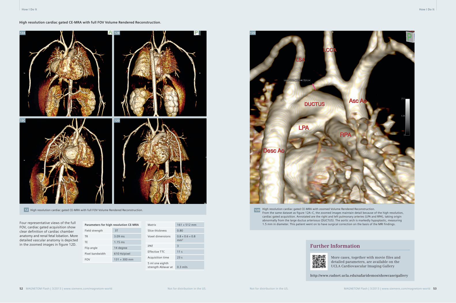
How I Do It How I Do It
Not for distribution in the US. MAGNETOM Flash | 3/2013 | www.siemens.com/magnetom-world 5352 MAGNETOM Flash | 3/2013 | www.siemens.com/magnetom-world Not for distribution in the US.
High resolution cardiac gated CE-MRA with full FOV Volume Rendered Reconstruction.
12A 12B
12C 12D
High resolution cardiac gated CE-MRA with full FOV Volume Rendered Reconstruction.12
Four representative views of the full FOV, cardiac gated acquisition show clear definition of cardiac chamber anatomy and renal fetal lobation. More detailed vascular anatomy is depicted in the zoomed images in figure 12D.
Parameters for high resolution CE-MRA
Field strength 3T
TR 3.09 ms
TE 1.15 ms
Flip angle 14 degree
Pixel bandwidth 610 Hz/pixel
FOV 131 × 300 mm
Matrix 161 × 512 mm
Slice thickness 0.80
Voxel dimensions 0.8 × 0.6 × 0.8 mm3
iPAT 3
Effective TTC 11 s
Acquisition time 23 s
5 ml one eighth strength Ablavar at 0.3 ml/s
High resolution cardiac gated CE-MRA with zoomed Volume Rendered Reconstruction.From the same dataset as figure 12A–C, the zoomed images maintain detail because of the high resolution, cardiac gated acquisition. Annotated are the right and left pulmonary arteries (LPA and RPA), taking origin abnormally from the large ductus arteriosus (DUCTUS). The aortic arch is markedly hypoplastic, measuring 1.5 mm in diameter. This patient went on to have surgical correction on the basis of the MRI findings.
12D
12D
Further Information
More cases, together with movie files and detailed parameters, are available on the UCLA Cardiovascular Imaging Gallery
http://www.radnet.ucla.edu/safaridemos/showcase/gallery

How I Do It
54 MAGNETOM Flash | 3/2013 | www.siemens.com/magnetom-world Not for distribution in the US.
Contact
J. Paul Finn, M.D.Diagnostic Cardiovascular ImagingDepartment of RadiologyDavid Geffen School of Medicine at UCLA 10833 Le Conte Ave.Los Angeles, CA [email protected]
References 1 Nael K, Krishnam M, Nael A, Ton A,
Ruehm SG, Finn JP. Peripheral contrast-enhanced MR angiography at 3.0T, improved spatial resolution and low dose contrast: initial clinical experience. Eur Radiol. 2008 Dec;18(12):2893-900. doi: 10.1007/s00330-008-1074-y. Epub 2008 Jul 11. PubMed PMID: 18618122.
2 Kramer JH, Grist TM. Peripheral MR Angiography. Magn Reson Imaging Clin N Am. 2012 Nov;20(4):761-76. doi: 10.1016/j.mric.2012.08.002. Epub 2012 Sep 25. Review. PubMed PMID: 23088949.
3 Krishnam MS, Tomasian A, Lohan DG, Tran L, Finn JP, Ruehm SG.
Low-dose, time-resolved, contrast-enhanced 3D MR angiography in cardiac and vascular diseases: correlation to high spatial resolution 3D contrast-enhanced MRA. Clin Radiol. 2008 Jul;63(7):744-55. doi: 10.1016/j.crad.2008.01.001. Epub 2008 Mar 28. PubMed PMID: 18555032.
4 Pasqua AD, Barcudi S, Leonardi B, Clemente D, Colajacomo M, Sanders SP. Comparison of contrast and noncontrast magnetic resonance angiography for quantitative analysis of thoracic arteries in young patients with congenital heart defects. Ann Pediatr Cardiol. 2011 Jan;4(1):36-40. doi: 10.4103/0974-2069.79621. PubMed PMID: 21677803; PubMed Central PMCID: PMC3104530.
5 Nael K, Ruehm SG, Michaely HJ, Saleh R, Lee M, Laub G, Finn JP. Multistation whole-body high-spatial-resolution MR angiography using a 32-channel MR system. AJR Am J Roentgenol. 2007 Feb;188(2):529-39. PubMed PMID: 17242265.
6 Fenchel M, Saleh R, Dinh H, Lee MH, Nael K, Krishnam M, Ruehm SG, Miller S, Child J, Finn JP. Time-resolved 3D contrast-enhanced MR Angiography in Adult Congenital Heart Disease. Radiology 2007 Aug;244(2):399-410.
7 Kim CY, Merkle EM. Time-resolved MR angiography of the central veins of the chest. AJR Am J Roentgenol. 2008 Nov;191(5):1581-8. doi: 10.2214/AJR.08.1027. PubMed PMID: 18941105.
8 Nael K, Saleh R, Nyborg GK, Fonseca CG, Weinmann HJ, Laub G, Finn JP. Pulmonary MR perfusion at 3.0 Tesla using a blood pool contrast agent: Initial results in a swine model. J Magn Reson Imaging. 2007 Jan;25(1):66-72. PubMed PMID: 17154181.
9 Fenchel M, Nael K, Deshpande VS, Finn JP, Kramer U, Miller S, Ruehm S, Laub G. Renal magnetic resonance angiography at 3.0 Tesla using a 32-element phased-array coil system and parallel imaging in 2 directions. Invest Radiol. 2006 Sep;41(9):697-703. PubMed PMID: 16896305.
10 Lohan DG, Krishnam M, Tomasian A, Saleh R, Finn JP. Time-resolved MR angiography of the thorax. Magn Reson Imaging Clin N Am. 2008 May;16(2):235-48, viii. doi: 10.1016/j.mric.2008.02.015. Review. PubMed PMID: 18474329.
11 Nael K, Fenchel MC, Kramer U, Finn JP, Ruehm SG. Whole-body contrast-enhanced magnetic resonance angiog-raphy: new advances at 3.0 T. Top Magn Reson Imaging. 2007 Apr;18(2):127-34. Review. Erratum in: Top Magn Reson Imaging. 2007 Aug;18(4):316. Gruehm, Stefan [corrected to Ruehm, Stefan G]. PubMed PMID: 17621226.
12 Young PM, McGee KP, Pieper MS, Binkovitz LA, Matsumoto JM, Kolbe AB, Foley TA, Julsrud PR. Tips and tricks for MR angiography of pediatric and adult congenital cardiovascular diseases. AJR Am J Roentgenol. 2013 May;200(5): 980-8. doi: 10.2214/AJR.12.9632. PubMed PMID: 23617479.
13 Nael K, Saleh R, Lee M, McNamara T, Godinez SR, Laub G, Finn JP, Ruehm SG. High-spatial-resolution contrast-enhanced MR angiography of abdominal arteries with parallel acquisition at 3.0 T: initial experience in 32 patients. AJR Am J Roentgenol. 2006 Jul;187(1):W77-85. PubMed PMID: 16794143.
14 Nael K, Laub G, Finn JP. Three-dimensional contrast-enhanced MR angiography of the thoraco-abdominal vessels. Magn Reson Imaging Clin N Am. 2005 May; 13(2):359-80. Review. PubMed PMID: 15935317.
15 Michaely HJ, Nael K, Schoenberg SO, Finn JP, Laub G, Reiser MF, Ruehm SG. The feasibility of spatial high-resolution magnetic resonance angiography (MRA) of the renal arteries at 3.0 T. Rofo. 2005 Jun;177(6):800-4. PubMed PMID: 15902628.
16 http://www.ablavar.com/home.html 17 http://imaging.bracco.com/us-en/
products-and-solutions/contrast-media/multihance
18 Reiter T, Ritter O, Prince MR, Nordbeck P, Wanner C, Nagel E, Bauer WR. Minimizing risk of nephrogenic systemic fibrosis in cardiovascular magnetic resonance. J Cardiovasc Magn Reson. 2012 May 20;14:31. doi: 10.1186/1532-429X-14-31. Review. PubMed PMID: 22607376; PubMed Central PMCID: PMC3409035.
19 Zou Z, Zhang HL, Roditi GH, Leiner T, Kucharczyk W, Prince MR. Nephrogenic systemic fibrosis: review of 370 biopsy-confirmed cases. JACC Cardiovasc Imaging. 2011 Nov;4(11):1206-16. doi: 10.1016/j.jcmg.2011.08.013. Review. PubMed PMID: 22093272.
20 Prince MR, Zhang HL, Prowda JC, Grossman ME, Silvers DN. Nephrogenic systemic fibrosis and its impact on abdominal imaging. Radiographics. 2009 Oct;29(6):1565-74. doi: 10.1148/rg.296095517. Review. PubMed PMID: 19959508.
21 Prince MR, Zhang HL, Roditi GH, Leiner T, Kucharczyk W. Risk factors for NSF: a literature review. J Magn Reson Imaging. 2009 Dec;30(6):1298-308. doi: 10.1002/jmri.21973. Review. PubMed PMID: 19937930.
22 Nael K, Moriarty JM, Finn JP. Low dose CE-MRA. Eur J Radiol. 2011 Oct;80(1): 2-8. doi: 10.1016/j.ejrad.2011.01.092. Epub 2011 Apr 1. Review. PubMed PMID: 21458187.
23 http://www.radnet.ucla.edu/safaridemos/showcase/gallery
MAGNETOM Flash · 2/2013 · www.siemens.com/magnetom-world 55
Pediatric Imaging ClinicalHow-I-do-it
MAGNETOM Flash · 2/2011 · www.siemens.com/magnetom-world 55
Get your free copy of the MR Angiography poster
Visit us at www.siemens.com/ magnetom-world Go to > Publications >
Subscriptions > MRI Poster
MR angiography is one of the most-performed exams in Magnetic Resonance Imaging (MRI). MRI offers not only visualization of vessel lumen like conventional angiography, but also the possibility to analyse the vessel walls. The Siemens application syngo TWIST even enables dynamic angiographical
imaging, with very low dose of contrast. And, with syngo NATIVE no contrast agent is used at all. With the Siemens-unique continuous table move, syngo TimCT, even a complete whole-body scan can be performed in a matter of minutes.
Battlefield Imaging, Ringgold, USA;
Benedictus Hospital, Tutzing, Germany;
Hong Kong Sanatorium & Hospital, Happy Valley, Hong Kong;
MR Bremen Mitte, Bremen, Germany;
Siemens AG, Healthcare Sector, Erlangen, Germany;
Tateyama Hospital, Tateyama, Japan;
University Hospital, Essen, Germany;
University Hospital Rechts der Isar, Munich, Germany;
University Hospital UCLA, Los Angeles, USA;
Answers for life.
www.siemens.com/CMR
MR Angiography
Ord
er N
o. A
91
MR-
11
00
-49
X-7
60
0 |
Prin
ted
in G
erm
any
| CC
41
5 0
41
2.5
| ©
04
.20
12
, Sie
men
s A
G

Siemens Healthcare PublicationsOur publications offer the latest information and background for every healthcare field. From the hospital director to the radiological assistant – here, you can quickly find information relevant to your needs.
Heartbeat Everything from the world of sustainable cardiovascular care.
MAGNETOM Flash Everything from the world of magnetic resonance imaging.
SOMATOM Sessions Everything from the world of computed tomography.
Medical Solutions Online The online version includes additional video features and greater depth to the articles in the printed healthcare leadership magazine. Read online at: www.siemens.com/medical-solutions
AXIOM Innovations Everything from the world of interventional radiology, cardiology, and surgery.
Imaging Life Everything from the world of molecular imaging innovations.
For current and past issues and to order the magazines, please visit www.siemens.com/healthcare-magazine
Not for distribution in the US. MAGNETOM Flash | 3/2013 | www.siemens.com/magnetom-world 5756 MAGNETOM Flash | 3/2013 | www.siemens.com/magnetom-world Not for distribution in the US.
Subscriptions Imprint
MAGNETOM Flash – Imprint
© 2013 by Siemens AG, Berlin and Munich, All Rights Reserved
Publisher: Siemens AG Medical Solutions Business Unit Magnetic Resonance, Karl-Schall-Straße 6, D-91052 Erlangen, Germany
Editor-in-Chief: Lars Drüppel, Ph.D. ([email protected])
Associate Editor: Antje Hellwich ([email protected])
Editorial Board: Wellesley Were; Ralph Strecker; Sven Zühlsdorff, Ph.D.; Gary R. McNeal, MS (BME); Peter Kreisler, Ph.D.; Dr. Sunil Kumar
Production: Norbert Moser, Siemens AG, Medical Solutions
Layout: independent Medien-Design Widenmayerstrasse 16, D-80538 Munich
Printer: G. Peschke Druckerei GmbH, Schatzbogen 35, D-81829 Munich, Germany
Note in accordance with § 33 Para.1 of the German Federal Data Protection Law: Despatch is made using an address file which is maintained with the aid of an automated data processing system.
MAGNETOM Flash with a total circulation of 35,000 copies is sent free of charge to Siemens MR customers, qualified physicians, technologists, physicists and radiology departments throughout the world. It includes reports in the English language on magnetic resonance: diagnostic and therapeutic methods and their application as well as results and experience gained with corresponding systems and solutions. It introduces from case to case new prin- ciples and procedures and discusses their clinical potential. The statements and views of the authors in the individual contribu-tions do not necessarily reflect the opinion of the publisher.
The information presented in these articles and case reports is for illustration only and is not intended to be relied upon by the reader for instruction as to the practice of medicine. Any health care practitioner reading this information is reminded that they must use their own learning, training and expertise in dealing with their individual patients. This material does not substitute for that duty and is not intended by Siemens Medical Solutions to be used for any purpose in that regard. The drugs and doses mentioned herein are consistent with the approval labeling for uses and/or indications of the drug. The treating physician bears the sole responsibility for the diagnosis and treatment of patients, including drugs and doses prescribed in connection with such use. The Operating Instructions must always be strictly followed when operating the MR system. The sources for the technical data are the corresponding data sheets. Results may vary.
Partial reproduction in printed form of indi-vidual contributions is permitted, provided the customary bibliographical data such as author’s name and title of the contribution as well as year, issue number and pages of MAGNETOM Flash are named, but the editors request that two copies be sent to them. The written consent of the authors and publisher is required for the complete reprinting of an article.
We welcome your questions and comments about the editorial content of MAGNETOM Flash. Please contact us at [email protected].
Manuscripts as well as suggestions, pro- posals and information are always welcome; they are carefully examined and submitted to the editorial board for attention. MAGNETOM Flash is not responsible for loss, damage, or any other injury to unsolicited manuscripts or other materials. We reserve the right to edit for clarity, accuracy, and space. Include your name, address, and phone number and send to the editors, address above.
MAGNETOM Flash is also available on the internet: www.siemens.com/magnetom-world

On account of certain regional limitations of sales rights and service availability, we cannot guarantee that all products included in this brochure are available through the Siemens sales organization worldwide. Availability and packaging may vary by country and is subject to change without prior notice. Some/All of the features and products described herein may not be available in the United States.
The information in this document contains general technical descriptions of specifications and options as well as standard and optional features which do not always have to be present in individual cases.
Siemens reserves the right to modify the design, packaging, specifications, and options described herein without prior notice. Please contact your local Siemens sales representative for the most current information.
Note: Any technical data contained in this document may vary within defined tolerances. Original images always lose a certain amount of detail when reproduced.
Order No. A91MR-1000-100C-7600 | Printed in Germany | CC MR 1320 08130.2 | © 08.13, Siemens AG
Local Contact Information
Asia/Pacific: Siemens Medical Solutions Asia Pacific Headquarters The Siemens Center 60 MacPherson Road Singapore 348615 Phone: +65 6490 6000
Canada: Siemens Canada Limited Healthcare Sector 1550 Appleby Lane Burlington, ON L7L 6X7, Canada Phone +1 905 315-6868
Europe/Africa/Middle East: Siemens AG, Healthcare Sector Henkestr. 127 91052 Erlangen, Germany Phone: +49 9131 84-0
Latin America: Siemens S.A., Medical Solutions Avenida de Pte. Julio A. Roca No 516, Piso C1067 ABN Buenos Aires, Argentina Phone: +54 11 4340-8400
USA: Siemens Medical Solutions USA, Inc. 51 Valley Stream Parkway Malvern, PA 19355-1406, USA Phone: +1 888 826-9702
Global Siemens Healthcare Headquarters
Siemens AG Healthcare Sector Henkestrasse 127 91052 Erlangen Germany Phone: +49 9131 84-0 www.siemens.com/healthcare
Global Siemens Headquarters
Siemens AG Wittelsbacherplatz 2 80333 Munich Germany
Global Business Unit
Siemens AG Medical Solutions Magnetic Resonance Henkestrasse 127 DE-91052 Erlangen Germany Phone: +49 9131 84-0 www.siemens.com/healthcare
www.siemens.com/magnetom-world
Not for distribution in the US