MPC3000 V3.0 Manual
276
MIDI PRODUCTION CENTER WARNING Software version 3.0 To prevent fire or shock hazard, do not expose this appliance to rain or moisture. Operator's Manual
Transcript of MPC3000 V3.0 Manual
MIDI PRODUCTION CENTER
WARNING
Software version 3.0
To prevent fire or shock hazard, do notexpose this appliance to rain or moisture.
Operator's Manual


MIDI PRODUCTION CENTER

MIDI Production Center
Software version 3.0
Operator’s Manual
By Roger Linn
Copyright 1987-1994 Akai Electric Co., LTD.
Document Revision date: May 1994
ii
WARNING!!To prevent fire or shock hazard, do not expose this appliance to rain or moisture.
1-En
The lightning flash with the arrowhead symbol superimposed across a graphicalrepresentation of a person, within an equilateral triangle, is intended to alert the userto the presence of uninsulated “dangerous voltage” within the product’s enclosure;that may be of sufficient magnitude to constitute a risk of electric shock.
The exclamation point within an equilateral triangle is intented to alert the userto the presence of important operating and maintenance (servicing) instructionsin the literature accompanying the appliance.
CAUTIONRISK OF ELECTRIC SHOCK
DO NOT OPEN
CAUTION: TO REDUCE THE RISK OF ELECTRIC SHOCK DO NOT REMOVE COVER (OR BACK).NO USER-SERVICEABLE PARTS INSIDE.REFER SERVICING TO QUALIFIED SERVICE PERSONNEL.
THE SYMBOLS ARE RULED BY UL STANDARDS (U.S.A).
5A-En
iii
WARNINGThe MPC3000 is designed to be used in a standard household environment.Power requirements for electrical equipment vary from area to area. Please ensurethat your MPC3000 meets the power requirements in your area. If in doubt, consulta qualified electrician or Akai Professional dealer.
120V @60Hz for USA and Canada
220V – 230/240V @50Hz for Europe
240V @50Hz for Australia
PROTECTING YOURSELF AND THE MPC3000• Never touch the AC plug with wet hands.
• Always disconnect the MPC3000 from the power supply by pulling on the plug, notthe cord.
• Allow only an “Akai Professional” dealer or qualified professional engineer torepair or reassemble the MPC3000. Apart from voiding the warranty, unautho-rized engineers might touch live internal parts and receive a serious electricshock.
• Do not put, or allow anyone to put any object, especially metal objects, into theMPC3000.
• Use only a household AC power source. Never use a DC power source.
• If water or any other liquid is spilled into or onto the MPC3000, disconnect thepower, and call your dealer.
• Make sure that the MPC3000 is well-ventilated, and away from direct sunlight.
• To avoid damage to internal circuitry, as well as the external finish, keep theMPC3000 away from sources of direct heat (stoves, radiators, etc.).
• Avoid using aerosol insecticides, etc. near the MPC3000. They may damage thesurface, and may ignite.
• Do not use denaturated alcohol, thinner or similar chemicals to clean theMPC3000. They will damage the finish.
• Place the MPC3000 on a flat and solid surface.
iv
WARNINGTHIS APPARATUS MUST BE EARTHED
IMPORTANTThis equipment is fitted with an approved non-rewireable UK mains plug.To change the fuse in this type of plug proceed as follows:
1) Remove the fuse cover and old fuse.2) Fit a new fuse which should be a BS1362 5 Amp A.S.T.A or BSI approved type.3) Refit the fuse cover.
If the AC mains plug fitted to the lead supplied with this equipment is not suitable for your type ofAC outlet sockets, it should be changed to an AC mains lead, complete with moulded plug, to theappropriate type. If this is not possible, the plug should be cut off and a correct one fitted to suitthe AC outlet. This should be fused at 5 Amps.
If a plug without a fuse is used, the fuse at the distribution board should NOT BE GREATER than 5 Amp.
PLEASE NOTE: THE SEVERED PLUG MUST BE DESTROYED TO AVOID A POSSIBLESHOCK HAZARD SHOULD IT BE INSERTED INTO A 13 AMP SOCKETELSEWHERE.
The wires in this mains lead are coloured in accordance with the following code:
GREEN and YELLOW —EARTHBLUE —NEUTRALBROWN —LIVE
As the colours of the wires in the mains lead of this apparatus may not correspond with thecoloured markings identifying the terminals in your plug, please proceed as follows:
The wire which is coloured GREEN and YELLOW must be connected to the terminal which ismarked with the letter E or with the safety earth symbol or coloured GREEN or colouredGREEN and YELLOW.The wire which is coloured BLUE must be connected to the terminal which is marked with theletter N or coloured BLACK.The wire which is coloured BROWN must be connected to the terminal which is marked withthe letter L or coloured RED.
THIS APPARATUS MUST BE EARTHED
Ensure that all the terminals are securely tightened and no loose strands of wire exist.Before replacing the plug cover, make certain the cord grip is clamped over the outer sheath ofthe lead and not simply over the wires.
6D-En
This equipment conforms to No. 82/499/EEC, 87/308/EEC standard
3A-En
CONFORME AL D.M. 13 APRILE 1989 DIRETTIVA CEE/87/308
3B-It
v
LITHIUM BATTERYThis product uses aLithium Battery for memory back-up. The lithium battery should only bereplaced by qualified service personnel. improper handling may cause risk of explosion.
24A-En
FCC warningThis equipment has been tested and found to comply with the limits for a Class A digitaldevice, pursuant to Part 15 of the FCC Rules. These limits are designed to providereasonable protection against harmful interference when the equipment is operated ina commercial environment. This equipment generates, uses, and can radiate radiofrequency energy and, if not installed and used in accordance with the instructionmanual, may cause harmful interference to radio communications. Operation of thisequipment in a residential area is likely to cause harmful interference in which case theuser will be required to correct the interference at his own expense.
21A-En
AVIS POUR LES ACHETEURS CANADIENS DU MPC3000Le présent appareil numérique n’ément pas des bruits radioélectriques dépassant leslimites applicables aux appareils numériques de la Class A prescrites dans le Règlementsur le brouillage radioélectrique édicté par le ministère des Communications du Canada.
27-F
This digital apparatus does not exceed the Class A limits for radio noise emissionsfrom digital apparatus set out in the Radio Interference Regulations of the CanadianDepartment of Communications.
27-En
FÜR KUNDEN IN DER BUNDESREPUBLIK DEUTSCHLANDBescheinigung von AKAIHiermit wird bescheinigt, daß das Gerät AKAI
MPC3000in Übereinstimmung mit den Bestimmungen der
Amtsblattverfügung 1046/1984funkentstört ist.Der Deutschen Bundespostwurde das Inverkehrbringen dieses Gerätes angezeigt unddie Berichtigung zur Überprüfung der Serie auf Einhaltung der Bestimmungen eingeräumt.AKAI ELECTRIC CO., LTD.
17B-G
COPYRIGHT NOTICEThe AKAI MPC3000 is a computer-based instrument, and as such contains and usessoftware in ROMs and disks. This software, and all related documentation, including thisOperator’s Manual, contain proprietary information which is protected by copyright laws. Allrights are reserved. No part of the software or its documentation may be copied, transferredor modified. You may copy the operating software and any samples, programs, etc.contained on disks for your own personal use. All other copies of the software are in violationof copyright laws. You may not distribute copies of the software to others, or transfer thesoftware to another computer by electronic means. You may not modify, adapt, translate,lease, distribute, resell for profit or create derivative works based on the software and itsrelated documentation or any part there of without prior written consent from AKAI ElectricCo., Ltd, Yokohama, Japan.
vi
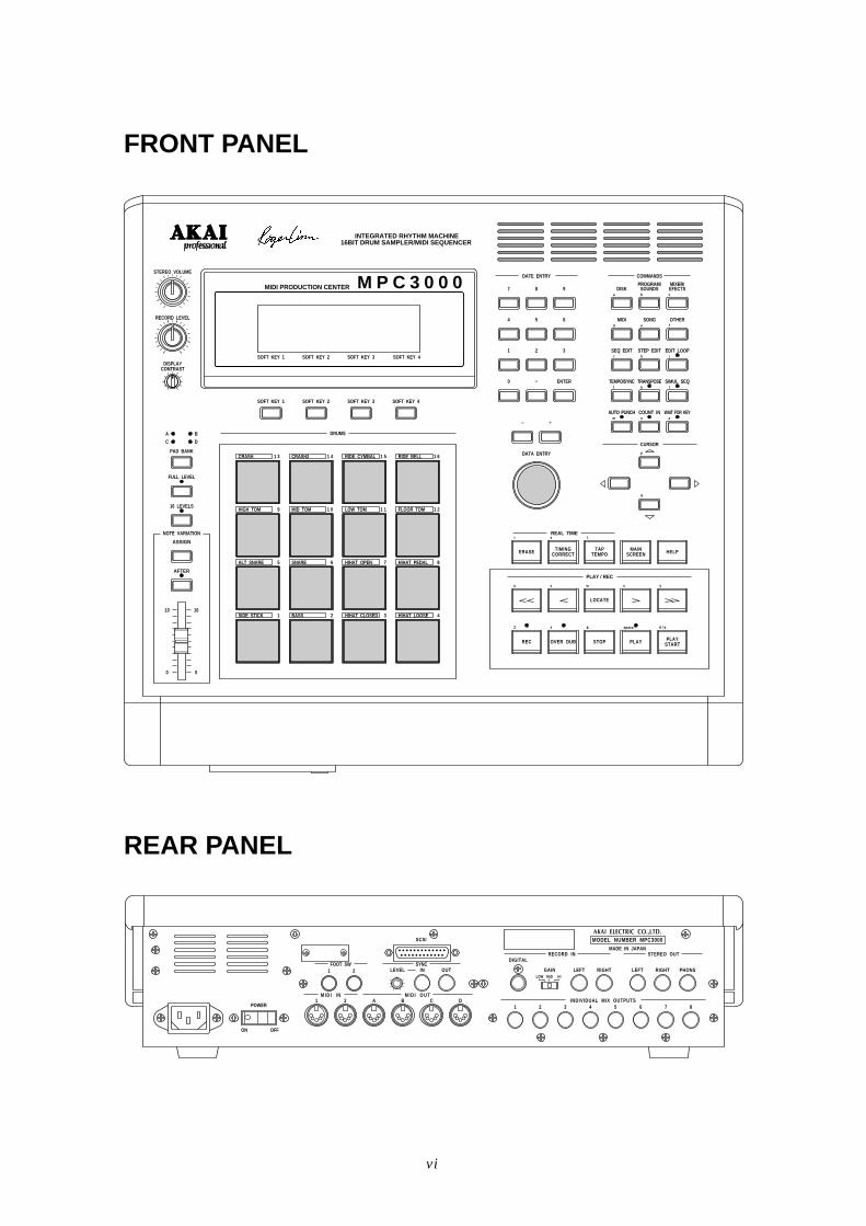
FRONT PANEL
TAPTEMPO
INTEGRATED RHYTHM MACHINE16BIT DRUM SAMPLER/MIDI SEQUENCER
STEREO VOLUME
RECORD LEVEL
MIDI PRODUCTION CENTER M P C 3 0 0 0
SOFT KEY 1DISPLAY
CONTRAST
SOFT KEY 2 SOFT KEY 3 SOFT KEY 4
DATE ENTRY COMMANDS
87 9
54 6
21 3
•0 ENTER
+–
DATA ENTRY
PROGRAM/SOUNDSDISK
MIXER/EFECTS
a b c
MIDId e f
SONG OTHER
SEQ EDITg h i
STEP EDIT EDIT LOOP
TEMPO/SYNCj k l
TRANSPOSE SIMUL SEQ
AUTO PUNCHn o
COUNT IN WAIT FOR KEYm
CURSOR
p
q
SOFT KEY 1 SOFT KEY 2 SOFT KEY 3 SOFT KEY 4
FULL LEVEL
PAD BANK
A
C
B
D
16 LEVELS
ASSIGN
AFTER
NOTE VARIATION
10
0
10
0
1 3 1 4 1 5 1 6
9 1 0 1 1 1 2
5 6 7 8
1 2 3 4
REAL TIME
ERASE
r
TIMINGCORRECT
s t
HELPMAINSCREEN
u v w
REC
Z # &
x y
PLAYSTART
space A / a
LOCATE
OVER DUB STOP PLAY
PLAY / REC
DRUMS
CRASH
HIGH TOM MID TOM LOW TOM FLOOR TOM
ALT SNARE HIHAT OPEN HIHAT PEDALSNARE
SIDE STICK BASS HIHAT CLOSED HIHAT LOOSE
CRASH2 RIDE CYMBAL RIDE BELL
REAR PANEL
POWER
ON OFF
FOOT SW1 2
M I D I I N1 D2 A B C
M I D I O U T
LEVEL IN OUTSYNC
SCSI
RECORD INDIGITAL
GAINLOW MID HI
LEFT RIGHT LEFT RIGHT PHONS
1 2 3 4 5 6 7 8
STEREO OUT
MODEL NUMBER MPC3000AKAI ELECTRIC CO.,LTD.
MADE IN JAPAN
INDIVIDUAL MIX OUTPUTS
vii
Table of Contents
Chapter 1: Introduction......................................................................................................... 1Welcome! ......................................................................................................................... 2Features .......................................................................................................................... 3What’s Different From the MPC60? .............................................................................. 6
If You Already Know the MPC60 ...................................................................... 8
Chapter 2: The Basics ........................................................................................................... 13Hooking Up Your System............................................................................................. 14Getting Around on the MPC3000 ................................................................................ 15
The Cursor, Cursor Keys, Data Fields, and Command Keys ........................ 15The Numeric Keypad, Data Entry Control, and [+] & [–] Keys .................... 16The Soft Keys ................................................................................................... 17The HELP key .................................................................................................. 18
Definitions: Sequence, Track, Song, Sound, Pad, Note Number, and Program ....... 19Loading and Playing Sounds and Programs ............................................................... 22
Playing the Pads, the PAD BANK, & FULL LEVEL Keys ........................... 22Selecting Programs .......................................................................................... 23The Note Variation Slider, ASSIGN and AFTER keys .................................. 24The 16 LEVELS key......................................................................................... 26
Chapter 3: Recording Sequences....................................................................................... 29How Sequences are Organized .................................................................................... 30The MAIN SCREEN Key & Play/Record Screen ........................................................ 32The Play/Record Keys .................................................................................................. 39Sequence Recording Example 1: A Looped Drum Pattern ......................................... 42Sequence Recording Example 2: A Multitrack Sequence........................................... 44The TIMING CORRECT Key: Correcting Timing Errors, Swing Timing ................ 49
The Note Repeat Feature ................................................................................ 52Tempo and the TEMPO/SYNC Key............................................................................. 53
Mid-Sequence Tempo Changes........................................................................ 56The TAP TEMPO Key ...................................................................................... 58
The WAIT FOR and COUNT IN Keys ........................................................................ 59The AUTO PUNCH Key .............................................................................................. 60The SIMUL SEQUENCE Key ..................................................................................... 62The OTHER Key........................................................................................................... 63
Metronome, Foot Switches, and Free Sequence Memory .............................. 63Initializing System Parameters ...................................................................... 66The Record 16 Channels Function: Multichannel Recording ........................ 67
Recording MIDI System-Exclusive Data .................................................................... 70
Chapter 4: Editing Sequences ............................................................................................ 71The ERASE Key ........................................................................................................... 72
Erasing Notes in Real Time While in Overdub Mode .................................... 72Erasing Notes or Other Events While Stopped .............................................. 72Initializing a Sequence .................................................................................... 75
The SEQ EDIT Key ...................................................................................................... 77Viewing and Changing Time Signature.......................................................... 77Rearranging the Track Order .......................................................................... 78Inserting Blank Bars Into a Sequence ............................................................ 79Deleting Bars From a Sequence ...................................................................... 80Copying Bars (All Tracks) ............................................................................... 81
viii
Copying Events ................................................................................................ 82Copying an Entire Sequence to Another ......................................................... 84Shifting the Timing of Many Notes ................................................................. 85Global Editing of Note Event Data ................................................................. 86
Editing Note Velocity or Duration Data ............................................. 87Editing Note Number Assignment of Drum Note Events ................. 89Editing Note Variation Data of Drum Note Events ........................... 90
The STEP EDIT Key .................................................................................................... 92Using Step Edit ................................................................................................ 93Step Edit Event Types ..................................................................................... 95Step Edit Options ............................................................................................. 99Step Recording ............................................................................................... 102
The EDIT LOOP Key ................................................................................................. 103Using Edit Loop as an Undo Function .......................................................... 104
The TRANSPOSE Key ............................................................................................... 105Transposing in Real Time While Playing ..................................................... 106
Chapter 5: Song Mode ........................................................................................................ 107Overview ..................................................................................................................... 108The SONG Key and Song Mode Screen .................................................................... 109An Example of Creating and Playing a Song............................................................ 112Converting a Song Into a Long Sequence ................................................................. 114
Chapter 6: Creating and Editing Programs .................................................................. 115What Are Programs? .................................................................................................. 116Selecting the Active Program, Assigning Sounds ..................................................... 119Envelope, Velocity Modulation, Tuning, Poly Mode ................................................. 125The Dynamic Filter .................................................................................................... 128Copying and Initializing Programs ........................................................................... 130
Chapter 7: The MIXER/EFFECTS Key ........................................................................... 133The Stereo Output Mixer ........................................................................................... 134The Individual Outputs/Effects Mixer ...................................................................... 136Viewing the Mix Data in Text Form ......................................................................... 139Mixer Source Select, Automated Mix ........................................................................ 142Effects Generator ....................................................................................................... 145
Chapter 8: Creating and Editing Sounds ...................................................................... 147Sampling a New Sound .............................................................................................. 148Editing a sound........................................................................................................... 154Renaming, Copying, and Deleting a Sound .............................................................. 158Triggering a Sound from an External Signal—the Audio Trigger .......................... 161
Chapter 9: Saving to and Loading from Disk ............................................................... 163Overview ..................................................................................................................... 164Saving Files ................................................................................................................ 166
Saving a SEQ File (Single Sequence) ............................................................ 166Saving an ALL File (All Sequences and Songs) ........................................... 167Saving a SND File (Single Sound) ................................................................ 168Saving a PGM File (Single Program & Sounds) ........................................... 169Saving an APS File (All Programs and Sounds) .......................................... 170Saving a PAR File (System Parameters) ...................................................... 172
ix
Loading, Erasing, or Renaming Files ........................................................................ 173Loading a SEQ File (Single Sequence) ......................................................... 175Loading an ALL File (All Sequences and Songs) ......................................... 177Loading a SND File (Single Sound) .............................................................. 177Loading a PGM File (Single Program and Sounds) ..................................... 178Loading an APS File (All Programs and Sounds) ........................................ 178Loading an MPC60 Version 1 or 2 SET or ST1 File ..................................... 179Loading a PAR File (System Parameters) .................................................... 182Files That Automatically Load on Power-Up ............................................... 182
Loading Sample Files From Akai S1000/S3000 Disks ............................................. 184Formatting a Floppy Disk .......................................................................................... 186Using a SCSI Hard Disk ............................................................................................ 187Copying an Entire Floppy Disk ................................................................................. 191
Chapter 10: Syncing to Tape and Other Devices ......................................................... 193The SYNC Screen ....................................................................................................... 194Syncing to Tape and Other Devices: Examples ........................................................ 201
Syncing to MIDI Clock ................................................................................... 201Syncing to SMPTE ......................................................................................... 201Syncing to MIDI Time Code .......................................................................... 204Syncing to FSK24 ........................................................................................... 204Syncing to 1/4-note Clicks.............................................................................. 206
Chapter 11: MIDI Functions ............................................................................................. 207Assigning Pads to Note Numbers .............................................................................. 208MIDI Receive Channel, Local Mode, Soft Thru, Note Variation Controller
Assign and Sustain Pedal Processing ................................................................. 210MIDI Input Filter ....................................................................................................... 213Turning All Notes Off ................................................................................................. 216The MIDI Implementation Charts ............................................................................ 217
Appendix ............................................................................................................................... 219Technical Specifications ............................................................................................. 220Answers to Frequent Questions ................................................................................ 222Contents of Disk Files ................................................................................................ 225MPC3000 Options ...................................................................................................... 229
The SMPTE Option ........................................................................................ 229Expanding the Sound Memory ...................................................................... 229The Video Output Option .............................................................................. 230
Index ...................................................................................................................................... 231

Chapter 1: Introduction
Page 1
Chapter 1:Introduction
Chapter 1: Introduction
Page 2
Welcome!
Since its release in 1988, the MPC60 MIDI Production Center hasearned a reputation not only as the world’s greatest drum machinebut also as a powerful sequencer for those who desire an alternativeto the complexity and confusion of computer sequencers.But over the years users asked for more: 16-bit stereo sampling,more sample memory, enhanced sound design features, fastersequence processing, enhanced sequence recording and editingfeatures, SCSI, and much more. The MPC3000 fulfills the majorityof the requests we received. And in keeping with the MPC60’stradition of ease of use, we have tried our best to implement thesenew features in the most intuitive way possible.
Since the advent of sequencers I have tracked their evolution withgreat interest and in my view, sequencers have evolved to a pointwhere they are now a legitimate instrument on their own. Many oftoday’s musicians could be better described as sequencer playersthan as keyboardists or guitarists. Album credits often read “pro-gramming by...” to denote a musician who has used a sequencer tocreate the backing track for a recording. These new musicians thinkand compose in terms of total arrangement as opposed to singleinstruments. In many ways, the sequencer’s panel and displayscreens are their strings and keys, allowing them to reach heights ofcreativity never before possible.
In this light, I like to think of the MPC3000 as the piano or violin ofour time, and of you as an MPC3000ist. In the same way a violinist’sstyle is identified by his or her vibrato and phrasing, your MPC3000virtuosity may be identified by your particular swing settings, yourcreative use of Note Repeat, or your real-time use of the NoteVariation feature. As an MPC3000ist, if you find the instrumentuseful in your creative process, please let the world know. Next timeyou perform on a recording, ask to be credited not with, “Keyboardsplayed by...” or “Programming by...” but rather with, “MPC3000played by....”
Thanks for buying the MPC3000. I hope you enjoy using it as muchas we have enjoyed creating it.
Chapter 1: Introduction
Page 3
Features
The following is a summary of some of the advanced features of theMPC3000.
General
• Large 320-character LCD display (8 lines by 40 characters) withgraphics.• Built-in 1.44 megabyte disk drive for storing both sequence andsound data.• Built-in SCSI interface for storing data to external hard disk.• Interactive Help function provides a full screen of explanation forevery data field of every function screen.• Four soft keys provide one-button execution of many functions.• The contents of many data fields and other settings are retainedwhile the power is turned off.• Fast internal 16MHz V53 16-bit microprocessor (equivalent to an80286) provides accurate timing in complex sequences and fastresponse to MIDI.
Sound Generator
• 16-bit, 44.1kHz stereo sampling.• High capacity sound memory: 2 megabytes standard (21.9 secondsmono or 10.9 seconds stereo), expandable to 16 megabytes (188.3seconds mono or 94.1 seconds stereo).• Digital sampling input for direct recording from digital sources.• 128 sounds (samples) may be held in memory at one time.• 32 simultaneous playback voices.• Dynamic lowpass filter with envelope generator (and resonance!)for each voice.• Built-in effects generator for versatile delay effects.• 10 polyphonic audio outputs, including stereo mix out and 8individual outputs.• 24 programs (sets of sound assignments) exist, each having 64unique sound assignments from a common bank of 128 sounds, andunique sound modifying parameters for each assignment. Switchingprograms instantly changes all sound assignments and soundparameters.• Multiple iterations of a single sound may be assigned to usemultiple voices (polyphonic) or the same voice (monophonic), andmay either respond to Note Off messages or not. Also, any soundmay be set to terminate the playing of any two other sounds.• Extensive sample editing allows any portion of a sound to becopied or removed and inserted into another sound at any location.Any portion may also be silenced or reversed.
Chapter 1: Introduction
Page 4
• The Best Start feature automatically finds the point within asound at which the drum strike begins, bypassing any dead space atthe beginning of the sound which could cause playback delays.• Up to three sounds can be assigned to a MIDI note number or pad.The sounds can either play simultaneously, switch depending onnote velocity, or switch depending on envelope decay (to simulatethe MPC60’s hi-hat decay slider function).• The stereo and individual output mixers are automated. Anychanges made while recording will be automatically repeated onplayback.
Sequencer
• Both linear and pattern-style (looped) recording are supported.• Both drum machine and sequencer-oriented features are inte-grated into one easy-to-use operating system.• 75,000 note sequencer capacity.• 99 sequences may be held in memory at once. Each sequencecontains 99 individual tracks, each of which can be output to anyone or two MIDI channels.• 4 independent MIDI output ports permit 64 simultaneous MIDIoutput channels.• 2 mergeable MIDI inputs.• The MPC3000 may be slaved to five sync sources: MIDI Clock,MIDI Time Code, FSK24, sync to any sound playing 1/4-notes, andSMPTE (optional).• 2 sequence record modes: Record (erasing existing notes whilerecording) and Overdub (merge with existing notes). You can switchbetween modes at any time.• Step Edit feature allows fast viewing, recording, editing, ordeletion of any event within a sequence.• The Simul Sequence feature allows two sequences, or one se-quence and one song, to play simultaneously. For example, you couldplay a short, looped drum sequence while simultaneously recordingyour multitrack keyboard sequence.• Versatile editing system allows erasing, time shifting, copying,merging, inserting, and deleting of any sequence data.• Individual parameters within note events may be changed formultiple notes globally.• Each track has an adjustable output level, allowing output veloci-ties to be scaled in real time while playing.• All 16 MIDI channels can be recorded simultaneously, allowingsequences to be transferred to the MPC3000 from an externalsequencer in one pass.• The Edit Loop feature allows a portion of a sequence to be loopedwhile overdubbing, and allows changes to be undone.• Sequences may be transposed, either in real time while playing orby altering note data.• The Tap Tempo feature allows the playback tempo to be set bytapping a key in the time of 1/4-notes.
Chapter 1: Introduction
Page 5
• Programmable tempo changes in mid-sequence or mid-song aresupported.• Mid-sequence time signature changes are supported.• Auto Punch feature allows automated punch-in and/or punch-outat preset times within the sequence.• Two foot switch inputs allow functions such as Play/Stop andPunch In/Out to be remotely controlled.• Swing feature provides a useful method of adjusting the rhythmicfeel of your tracks.• 16 velocity- and pressure-sensitive front panel drum pads and 4pad banks provide a total of 64 pad/bank combinations.• Note Variation feature allows a unique value of tuning, decay,attack or filter frequency to be recorded with each drum note.• MIDI sustain pedal messages can be specially processed so thatmultiple overdubs on the same track of a sequence can use thesustain pedal independently, without interaction.
Chapter 1: Introduction
Page 6
What’s Different From the MPC60?
The MPC3000 contains many changes and improvements over theMPC60. The major changes are listed below.
Sound Generator Changes
• Sampling resolution is increased from 12-bit non-linear to 16-bitlinear.• Sampling rate is increased from 40 kHz to 44.1 kHz.• Stereo sampling is supported.• A digital sampling input is included for direct recording fromdigital sources.• Sound memory is increased: 2 megabytes standard (21.9 secondsmono or 10.9 seconds stereo), expandable to 16 megabytes (188.3seconds mono or 94.1 seconds stereo). The maximum sampling timeper sound is no longer limited to 5 seconds, but rather only byavailable sound memory. Also, sampling no longer requires erasingsequence memory.• Total sound capacity is increased from 34 to 128 sounds.• Number of playback voices is increased from 16 to 32.• A dynamic lowpass filter with envelope generator (and resonance)exists for each playback voice.• A built-in effects generator permits versatile delay effects.• The new programs system of sound assignment allows all soundassignments to be instantly changed merely by changing the activeprogram number, instead of by loading a new SET file as in theMPC60. There are 24 programs, each with a unique set of soundassignments from a common bank of 128 sounds. Unlike Set files,saving a program to disk only saves assignment and parameterinformation; the sounds used by the program are saved as indi-vidual sound files. This allows multiple programs to be saved to thesame disk without redundantly saving sound data as with SET files.• Sounds are now assigned to MIDI note numbers instead of to padnames. This permits simpler operation of the MPC3000 as a MIDIsound module, eliminating the need to translate MIDI note numbersinto pad names as in the MPC60.• New Mono Mode parameter causes a voice to restart, terminatingearlier plays. Also, any sound can be set to terminate any two othersounds.• Sample files from Akai S1000 & S3000 floppy disks may be loaded.• Sample editing is enhanced. Now, any portion of a sound may becopied or removed and then inserted into another sound at anylocation. Also, any portion may be silenced or reversed.• The Echo Mixer has been removed. It is replaced by the IndividualOutputs/Effects Mixer. This new mixer allows any sound to berouted to any one of the individual outputs or the internal effectsgenerator, and the volume level of this assignment is adjustableindependently of the stereo volume.
Chapter 1: Introduction
Page 7
This allows independent send-level mixing to the internal effectsgenerator, or for any one of the individual outputs to be used as afull external echo send mixer.• The Double Play feature has been removed. Instead, up to threesounds can be assigned to play from an incoming MIDI note numberor pad. The sounds can either play simultaneously, switch depend-ing on note velocity, or switch depending on envelope decay (tosimulate the MPC60’s hi-hat decay slider function).• The Best Start feature automatically finds the point within asound at which the drum strike begins, bypassing any dead space atthe beginning of the sound which could cause playback delays.• The envelope decay parameter is now switchable between twomodes: END (same as the MPC60’s Fadeout parameter) and START(decay begins immediately following attack).
Sequencer Changes
• Sequence memory capacity is expanded by 30% to 75,000 notes.• In Step Edit , the REWIND [<] and FAST FORWARD [>] keysmay now be used to search to the previous or next event within atrack.• In Step Edit, events may be cut and pasted by changing thefunction of soft keys 1 and 2 from <Insert> and <Delete> to <Paste>and <Cut>.• The number of pad banks has been increased from 2 to 4 for atotal of 64 pad/bank combinations. The active pad bank is indicatedby the LEDs above the PAD BANK key.• In drum tracks, drum notes are now assigned to MIDI notenumbers instead of to pads. This provides easier compatibility withexternal MIDI devices and allows pad assignments to be rearrangedwithout affecting sequence or program data. MPC60 version 2sequences are automatically converted from pad assignment to notenumber assignment when loaded.• The MPC60’s fixed four-letter drum names are no longer used.Instead, notes in drum tracks are visually identified in editingscreens by pad number, MIDI note number and currently assignedsound name.• The new Note Variation Slider replaces the MPC60’s Hi-hat DecaySlider, expanding its capabilities to provide a unique value of eitherdecay, tuning, attack, or filter frequency for every note.• The 16 Levels function can now provide 16 levels of velocity,tuning, attack, decay or filter frequency for every note.• The Copy/Merge a Track feature has been renamed to CopyEvents and now permits specific drum notes to be copied.• The Change Velocity/Duration feature now allows specific drumnotes to be edited.• The new Shift Timing feature shifts track timing independently oftiming correction.
Chapter 1: Introduction
Page 8
• The new Edit Note Number Assignment feature permitsreassigning specific drum notes from one note number(instrument) to another.• The Count In feature may now be set to activate only beforerecording.• The Punch In feature may now be set to punch-in only orpunch-out only.• New MIDI Local Mode internally disconnects the pads from thesound generator. This is useful when using the pads and soundgenerator with external sequencers.
General Changes
• Floppy disk capacity is expanded to 1.44 megabytes.• Built-in SCSI interface allows data to be saved to and loaded fromexternal hard disk.• Faster internal computer (16MHz V53—equivalent to a 80286) forimproved timing accuracy in complex sequences and enhancedtiming response to MIDI input.• Many screens are changed and some functions moved in order tomake operation simpler and more intuitive.
If You Already Know the MPC60
Most of the operational differences between the MPC60 andMPC3000 should be relatively simple to understand for MPC60users, but some changes are more complex than others. Here isadditional information about the more complex changes to theMPC3000.
The new Programs system
The MPC3000 uses a new system of sound assignments calledprograms. A program is a set of 64 sound assignments andsound modifying parameters. There are 24 different programs,each with a unique set of sound assignments to a commonbank of up to 128 sounds in memory. Only one program maybe active at a time. As result of this new system, changing apad’s assignment from one sound to another is done merely bychanging the contents of a data field. Changing from oneentire set of sound assignments to another is done by changingthe active program number. In addition to the soundassignments, each program contains a unique set of soundmodifying parameters for each sound assignment. Theseparameters include envelope, tuning, velocity modulation,
Chapter 1: Introduction
Page 9
dynamic filter and other data. This is explained further in Chapter6: “Creating and Editing Programs”.
MPC60 SET files are replaced by the new Program files.
In the MPC60, all sounds and sound assignments are saved inone large SET file. In order to change all pad assignments, itis necessary to load a new SET file. Because of the MPC3000’snew Program system of sound assignments, SET files havebeen replaced by PGM (program) files. A PGM file containsall assignment information but no sound data. Instead, whena PGM file is saved, all sounds used by the program are alsosaved as individual sound files. This new method allowsdifferent PGM files on the same disk to use the same soundfiles, eliminating the problem of saving sound data redundantlyin multiple SET files. However, SET files may be loaded—theassignments are loaded into a program and the sounds are addedto sound memory.
There is another new save operation called Save All Programs andAll Sounds. This saves a file with the extension APS containing thedata of all 24 programs, followed by a sound file for every soundcurrently in memory.
Saving of PGM and APS files is explained further in chapter 9:“Saving To and Loading From Disk”.
Sounds and sequenced drum notes are now assigned to notenumbers instead of to pad names.
In the MPC60, sounds and sequenced drum notes are assigned toone of a number of fixed drum pad names (HIHT, SNR1, DR01 etc.)In the MPC3000, sounds in programs and drum notes in sequencesare assigned instead to one of 64 MIDI note numbers (35-98), as areeach of the 64 pad/bank combinations (A01-D16). The fixed 4character drum names are no longer used. This new note numberassignment method provides the following advantages over theMPC60’s pad-assign method:
1. Because pads are assigned to MIDI note numbers inde-pendently of sound assignments in programs or noteassignments in drum tracks, the pad assignments may befreely rearranged to personal preference without affectingsequences or sound assignments.
2. When using the MPC3000 as a sound generator, it is nolonger necessary to use the MPC60’s “Assign incomingnotes to pads” conversion table, which has been removed.Instead, simply assign the received MIDI note numberdirectly to a sound.
Chapter 1: Introduction
Page 10
3. Notes may be recorded from MIDI directly into drumtracks without the need for the MPC60’s “Assign incom-ing notes to pads” conversion table, which has beenremoved. Now, when viewing a drum note in Step Edit,the actual MIDI note number received is displayed, aswell as the currently assigned pad number (A01-D16) andsound name.
4. Drum notes are sent out over MIDI without the need forthe MPC60’s “Assign pads to outgoing note numbers”conversions, a function which has been removed. Whenviewing a drum note in Step Edit, the actual MIDI notenumber displayed is sent out.
When MPC60 SEQ or ALL files are loaded, a screen is presentedexplaining that the pad assignments of drum notes will be convertedto note number assignments and offering conversion options.
For a more detailed explanation of how the MPC3000 uses notenumbers, please refer to the beginning of chapters 6 and 11: “Creat-ing and Editing Programs” and “MIDI Functions”.
Assigning tracks as either Drum or MIDI
In the MPC60, a track is assigned to drums by assigning its outputMIDI channel to the Drums Channel, which is the input MIDIchannel of the internal sound generator. In the MPC3000, assigninga track to drums is simpler: a new data field in the Play/Recordscreen permits each track to be assigned as either DRUM or MIDI.MIDI tracks contain normal MIDI data recorded from the MIDIinput and played out through the MIDI outputs. Drum tracks arethe same as MIDI tracks except for the following:
1. The output of the track plays to the internal drum soundgenerator.
2. You can record drum notes into the track using the frontpanel pads.
3. In sequence editing screens, note events in Drum tracksare visually identified and selected not by note numberonly as in MIDI tracks, but also by the pad number andsound name currently assigned to the displayed notenumber.
4. Drum tracks are not affected by the Transpose function.
Independently, each track (DRUM or MIDI) may be assigned to anyMIDI channel and MIDI output port. As a result of this change, theMPC60’s Drums Channel and Drum Data Sent Out fields have beenremoved.
Chapter 1: Introduction
Page 11
New Note Variation system and revised 16 Levels function
In the MPC60, the Hi-hat Decay Slider controlled decay time andsound selection for the hi-hat pad only. In the MPC3000, the newNote Variation Slider provides all functions of the hi-hat decayslider, but may be assigned to any pad and may alternately controleither tuning, attack or filter frequency. As with the Hi-hat DecaySlider, this information is recorded into each drum note.
The 16 Levels function does everything it did in the MPC60. Inaddition, it can produce 16 levels of either attack, decay or filterfrequency by working in conjunction with the Note Variation sys-tem.
Delete Bars and Copy Bars: Last bar field has different func-tion that MPC60’s To bar field
In the Delete Bars function, the Last Bar field now contains theactual last bar of the region to be deleted. This is different from theMPC60’s To Bar field that contained the first bar after the region tobe deleted.
In the Copy Bars function, the Last Bar field now contains theactual last bar of the region to be copied. This is different from theMPC60’s To Bar field that contained the first bar after the region tobe copied.
Chapter 2: The Basics
Page 13
Chapter 2:The Basics
Chapter 2: The Basics
Page 14
Hooking Up Your System
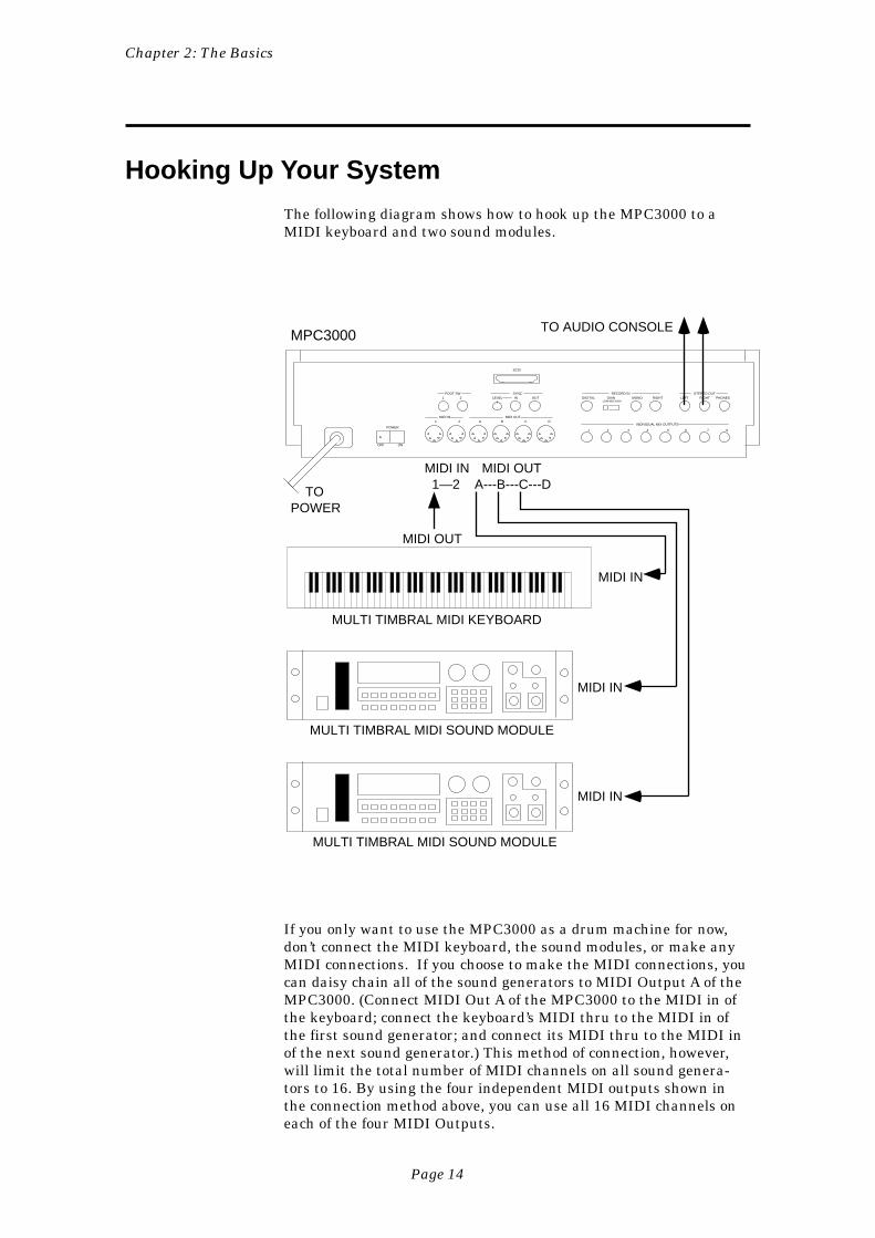
The following diagram shows how to hook up the MPC3000 to aMIDI keyboard and two sound modules.
MULTI TIMBRAL MIDI KEYBOARD
MULTI TIMBRAL MIDI SOUND MODULE
MIDI IN
MIDI OUTA---B---C---D
MIDI IN1—2
MIDI IN
MPC3000TO AUDIO CONSOLE
MIDI OUT
MULTI TIMBRAL MIDI SOUND MODULE
MIDI IN
INDIVIDUAL MIX OUTPUTS
1
MIDI OUTMIDI IN
1 2 IN OUTSYNCFOOT SW
LEVEL PHONESLEFTDIGITAL GAINLOW MID HIGH
RECORD IN
OFF ON
POWER
RIGHTMONO RIGHT
2 3 4 5 6 7 8
1 2 A B C D
SCSI
STEREO OUT
TOPOWER
If you only want to use the MPC3000 as a drum machine for now,don’t connect the MIDI keyboard, the sound modules, or make anyMIDI connections. If you choose to make the MIDI connections, youcan daisy chain all of the sound generators to MIDI Output A of theMPC3000. (Connect MIDI Out A of the MPC3000 to the MIDI in ofthe keyboard; connect the keyboard’s MIDI thru to the MIDI in ofthe first sound generator; and connect its MIDI thru to the MIDI inof the next sound generator.) This method of connection, however,will limit the total number of MIDI channels on all sound genera-tors to 16. By using the four independent MIDI outputs shown inthe connection method above, you can use all 16 MIDI channels oneach of the four MIDI Outputs.
Chapter 2: The Basics
Page 15
Getting Around on the MPC3000
Before you can use the MPC3000, you must learn how to use thecursor keys, data fields, command keys, the data entry keys anddata entry control, the soft keys and the HELP key.
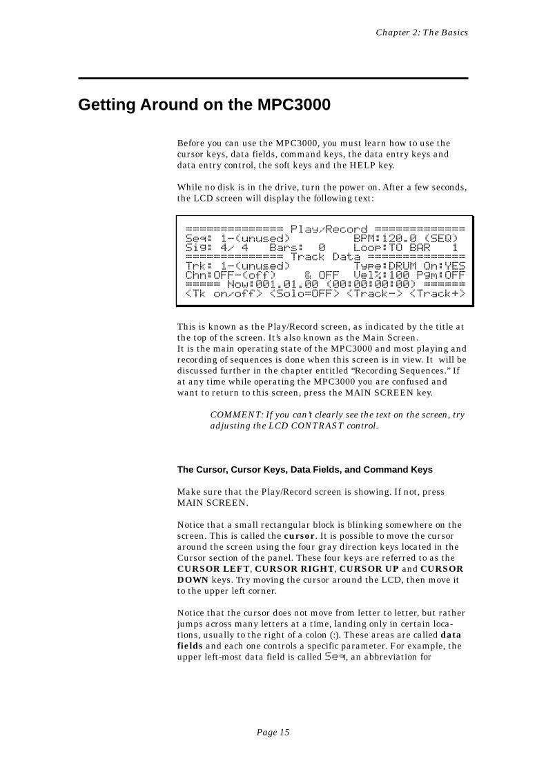
While no disk is in the drive, turn the power on. After a few seconds,the LCD screen will display the following text:
============== Play/Record =============Seq: 1-(unused) BPM:120.0 (SEQ)Sig: 4/ 4 Bars: 0 Loop:TO BAR 1============== Track Data ==============Trk: 1-(unused) Type:DRUM On:YESChn:OFF-(off) & OFF Vel%:100 Pgm:OFF===== Now:001.01.00 (00:00:00:00) ======<Tk on/off> <Solo=OFF> <Track-> <Track+>
This is known as the Play/Record screen, as indicated by the title atthe top of the screen. It’s also known as the Main Screen.It is the main operating state of the MPC3000 and most playing andrecording of sequences is done when this screen is in view. It will bediscussed further in the chapter entitled “Recording Sequences.” Ifat any time while operating the MPC3000 you are confused andwant to return to this screen, press the MAIN SCREEN key.
COMMENT: If you can’t clearly see the text on the screen, tryadjusting the LCD CONTRAST control.
The Cursor, Cursor Keys, Data Fields, and Command Keys
Make sure that the Play/Record screen is showing. If not, pressMAIN SCREEN.
Notice that a small rectangular block is blinking somewhere on thescreen. This is called the cursor. It is possible to move the cursoraround the screen using the four gray direction keys located in theCursor section of the panel. These four keys are referred to as theCURSOR LEFT, CURSOR RIGHT, CURSOR UP and CURSORDOWN keys. Try moving the cursor around the LCD, then move itto the upper left corner.
Notice that the cursor does not move from letter to letter, but ratherjumps across many letters at a time, landing only in certain loca-tions, usually to the right of a colon (:). These areas are called datafields and each one controls a specific parameter. For example, theupper left-most data field is called Seq, an abbreviation for
Chapter 2: The Basics
Page 16
sequence. To the right of this field is another field containing thename for the selected sequence.
The Play/Record screen is one of many display screens available onthe MPC3000. Most of the panel keys present a unique screen, andeach screen has its own unique data fields. Try pressing a few of thedifferent keys in the Commands section of the panel, such as DISKor TEMPO/SYNC.
The Numeric Keypad, Data Entry Control, and [+] & [–] Keys
Make sure that the Play/Record screen is showing. If not, pressMAIN SCREEN.
To change the data in a data field, move the cursor to the field andtype in the new number using the numeric keypad, followed byENTER. For example, to change to sequence number 2:
1. Move the cursor to the Seq field in the upper left corner;2. Type 2, followed by the ENTER key.
Notice that the sequence name (located immediately to the right ofthe sequence number) now changes automatically, because it mustnow display the name of sequence 2.
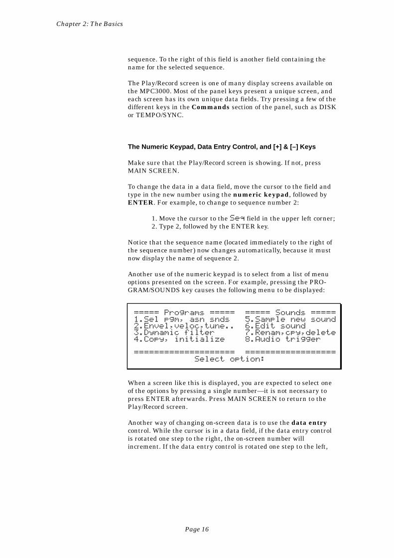
Another use of the numeric keypad is to select from a list of menuoptions presented on the screen. For example, pressing the PRO-GRAM/SOUNDS key causes the following menu to be displayed:
===== Programs ===== ===== Sounds =====1.Sel pgm, asn snds 5.Sample new sound2.Envel,veloc,tune.. 6.Edit sound3.Dynamic filter 7.Renam,cpy,delete4.Copy, initialize 8.Audio trigger
==================== ================== Select option:
When a screen like this is displayed, you are expected to select oneof the options by pressing a single number—it is not necessary topress ENTER afterwards. Press MAIN SCREEN to return to thePlay/Record screen.
Another way of changing on-screen data is to use the data entrycontrol. While the cursor is in a data field, if the data entry controlis rotated one step to the right, the on-screen number willincrement. If the data entry control is rotated one step to the left,
Chapter 2: The Basics
Page 17
the on-screen number will decrement. Continuously turning thedata entry control will repeatedly increment or decrement the on-screen value. It is not necessary to press ENTER after turning thedata entry control.
There is a special type of data field called a choice field. Fields ofthis type do not contain numeric data, but rather a specific numberof preset text selections, though only one can be active at a time. Inthis case, the data entry control is used to select from the availableoptions. For example, press the OTHER key and move the cursor tothe Rate field, which is a choice field. Now turn the data entrycontrol and notice that with each step of the control, a differentpreset option appears in the data field. When finished, set this fieldback to 1/4 NOTE.
Pressing the [+] key has the same effect as turning the data entrycontrol one step to the right. It either increments a number in anumeric field or chooses the next option in a choice field.
Pressing the [-] key has the same effect as turning the data entrycontrol one step to the left. It either decrements a number in anumeric field or chooses the previous option in a choice field.
The Soft Keys
Make sure that the Play/Record screen is showing. If not, pressMAIN SCREEN.
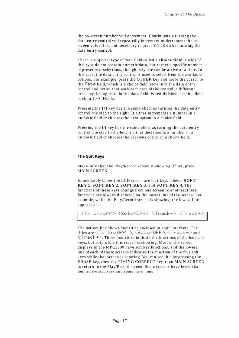
Immediately below the LCD screen are four keys labeled SOFTKEY 1, SOFT KEY 2, SOFT KEY 3, and SOFT KEY 4. Thefunctions of these keys change from one screen to another; thesefunctions are always displayed on the lowest line of the screen. Forexample, while the Play/Record screen is showing, the lowest lineappears as:
<Tk on/off> <Solo=OFF> <Track-> <Track+>
The bottom line shows four titles enclosed in angle brackets. Thetitles are <Tk On/Off >, <Solo=OFF>, <Track-> and<Track+>. These four titles indicate the functions of the four softkeys, but only while this screen is showing. Most of the screendisplays in the MPC3000 have soft key functions, and the lowestline of each of these screens indicates the function of the four softkeys while that screen is showing. You can see this by pressing theERASE key, then the TIMING CORRECT key, then MAIN SCREENto return to the Play/Record screen. Some screens have fewer thanfour active soft keys and some have none.
Chapter 2: The Basics
Page 18
The HELP key
Whenever this key is pressed and held down, the contents of thescreen will be temporarily replaced by text explaining the functionof the data field where the cursor is currently located. To return tothe previous screen, release the HELP key. There is a different helpscreen for every data field of every screen in the MPC3000.
Chapter 2: The Basics
Page 19
Definitions: Sequence, Track, Song, Sound, Pad,Note Number, and Program
Here are some definitions of terms used in the MPC3000 that youshould know:
Sequence
A sequence can be thought of as a segment of multitrack tape ofvariable length. Depending on the sequence contents, it could be atwo-bar repeating drum pattern, an eight-bar verse, or an entire200-bar multitrack composition with time signature and tempochanges. The MPC3000 holds 99 sequences in memory at one time.Normally, only one sequence can play at one time, unless the SimulSequence feature is on, which allows two sequences or one sequenceand one song to play simultaneously.
Track
Within each of the 99 sequences are 99 tracks that contain theactual MIDI events. These can be thought of as the tracks on amultitrack tape recorder—they each contain a specific instrument orpiece of the total arrangement, but they all play simultaneously. Forexample, track 1 could be drums, track 2 percussion, track 3 bass,track 4 piano, track 5 horns, track 6 more horns, etc. Each track canbe assigned as a Drum track or a MIDI track, but not both. MIDItracks contain normal MIDI data recorded from the MIDI input andplayed out through the MIDI output. Drum tracks are the same asMIDI tracks except for the following:
1. The output of the track plays to the internal drum soundgenerator.
2. You can record drum notes into the track using the frontpanel pads.
3. In sequence editing screens, note events in drum tracksare visually identified and selected not by note numberonly as in MIDI tracks, but also by the pad number andsound name currently assigned to the displayed notenumber.
4. Drum tracks are not affected by the Transpose function.
Song
A song is a list of sequences that play consecutively, with eachsequence representing a section of a composition. In the MPC3000there are 20 songs, each having up to 250 steps. Each step holdsone sequence and can repeat a specified number of times before thesong moves to the next step.
Chapter 2: The Basics
Page 20
Sound
Each individual sampled recording in the MPC3000 is called asound. A sound could be a recording of a single strike of a snaredrum or cymbal, a sound effect, or a 30 second stereo recording ofbacking vocals. Sounds are sampled in 16-bit linear format at asampling rate of 44.1kHz in either mono or stereo and can be anylength up to the limit of sound memory. A maximum of 128 soundscan reside in sound memory.
Pad
When sounds are loaded into the MPC3000, each pad plays aparticular sound. Though there are only 16 pads, the MPC3000 canhold many more than 16 sounds, To access more than 16 soundsfrom the pads, the MPC3000 provides four banks of pad assign-ments permitting up to 64 sounds to be played from the 16 pads.Only one bank can be active at a time. The four banks are named A,B, C, and D, and the pads are numbered 1 through 16. The 64 bank/pad combinations are named by combining the bank letter (A-D)with the pad number:
Pads in bank A: A01 through A16Pads in bank B: B01 through B16Pads in bank C: C01 through C16Pads in bank D: D01 through D16
Each of these 64 bank/pad combinations (A01-D16) is referred to asa pad.
Notice that sounds are not assigned directly to pads, but rather toMIDI Note Numbers. In order for a pad to play a sound, it is firstassigned to a MIDI note number, then that note number is assignedto a sound. This is described further in the “MIDI Functions” and“Creating and Editing Programs” chapters of this manual.
Note Number
In MIDI terminology, note number refers to the element in a MIDINote On event that supplies the pitch of the note. The note numberrange is from 0 to 127. For example, if Middle C is played on a MIDIkeyboard, a Note On event is sent out over MIDI containing notenumber 60; the receiving sound generator interprets this as MiddleC and plays the appropriate pitch. If the sound generator is playingdrum sounds, the note number is not used for pitch, but rather to
Chapter 2: The Basics
Page 21
select which drum will play—one key for bass drum, one for snare,one for high tom, etc.
This system of using MIDI note numbers to select drums is used inthe MPC3000’s sound assignment system. In programs (describedbelow), sounds are assigned directly to one of 64 MIDI note numbers(35-98). In sequences, drum notes are also assigned to one of 64 notenumbers (35-98) to indicate which sound to play. Because of thisassignment method, there are many data fields in the MPC3000called Note, in which you enter either the note number you wish toassign in a program, or the note number you wish to edit in asequence’s drum track. (For easy visual identification in theseNote fields, the note number is accompanied by both the currentlyassigned pad number and sound name. )
Program
Once a sound is loaded into memory, it cannot be played by pads orfrom MIDI until it is assigned within a program. A program is acollection of 64 sound assignments and can be thought of as a drumset. In a program, each of 64 MIDI note numbers (35-98) is assignedto one of the 128 possible sounds currently residing in memory. Onceassigned to a note number, a sound can be played in one of threeways:
1. By receiving a Note On message from the MIDI input;2. By playing a front panel drum pad (each pad is also assigned to
one of the 64 MIDI note numbers 35-98);3. By playing drum tracks in sequences (each note event in a drum
track is assigned to one of the 64 MIDI note numbers 35-98).
In addition to the 64 sound assignments, each program also con-tains a number of sound modifying parameters for each of the 64sound assignments, including envelope, tuning, filter, mixer, andvelocity response data. Each program also contains some param-eters, such as the settings of the effects generator, that collectivelyaffect all sounds.
The MPC3000 has 24 different programs (one of which can be activeat a time) each with its own unique set of 64 assignments. Simply bychanging the active program number (1-24), all 64 sound assign-ments and their sound modifying settings will instantly change.
Chapter 2: The Basics
Page 22
Loading and Playing Sounds and Programs
All sounds and programs are held in RAM memory and are there-fore lost whenever the power is turned off. In order to play anysounds after turning the power on, you must load them in from disk.The procedure for loading files from disk is described in the “SavingTo and Loading From Disk” chapter of this manual, but to get youstarted quickly, you’ll learn how to load a disk automatically whenthe power is turned on. Follow these steps:
1. Of the 4 sound disks that are included with the MPC3000, selectone and place it in the disk drive. Each disk contains a variety ofdrum sounds and programs.
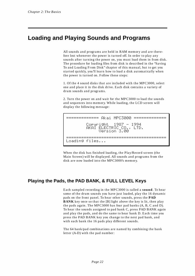
2. Turn the power on and wait for the MPC3000 to load the soundsand sequences into memory. While loading, the LCD screen willdisplay the following message:
============= Akai MPC3000 =============
Copyright 1987 - 1994 AKAI ELECTRIC CO., LTD. Version 3.00
========================================Loading files...
When the disk has finished loading, the Play/Record screen (theMain Screen) will be displayed. All sounds and programs from thedisk are now loaded into the MPC3000’s memory.
Playing the Pads, the PAD BANK, & FULL LEVEL Keys
Each sampled recording in the MPC3000 is called a sound. To hearsome of the drum sounds you have just loaded, play the 16 dynamicpads on the front panel. To hear other sounds, press the PADBANK key once so that the [B] light above the key is lit, then playthe pads again. The MPC3000 has four pad banks (A, B, C and D).To hear the sounds assigned to pad bank C, press PAD BANK againand play the pads, and do the same to hear bank D. Each time youpress the PAD BANK key you change to the next pad bank, andwith each bank the 16 pads play different sounds.
The 64 bank/pad combinations are named by combining the bankletter (A-D) with the pad number:
Chapter 2: The Basics
Page 23
Pads in bank A: A01 through A16Pads in bank B: B01 through B16Pads in bank C: C01 through C16Pads in bank D: D01 through D16
Each of these 64 bank/pad combinations (A01-D16) is referred to asa pad.
The 16 pads are dynamic—the harder you play them, the louder thesound will play. If desired, however, this touch sensitivity can bedefeated. Press the FULL LEVEL key (the light goes on), and nomatter how hard you play the pads, the sound will play at itsmaximum dynamic level. Press FULL LEVEL again to return tonormal dynamic operation.
Selecting Programs
The 64 sound assignments you have just heard (four pad banks of 16sounds each) comprise a program. The MPC3000 can hold up to 24programs. Each program has a unique set of 64 sound assignments,so you can think of programs as drum sets. If you change from oneprogram to another, playing the four banks of pads will produceentirely different sounds.
When you just played the pads and heard the sounds, you werehearing the sounds assigned in Program 1. To change to Program 2:
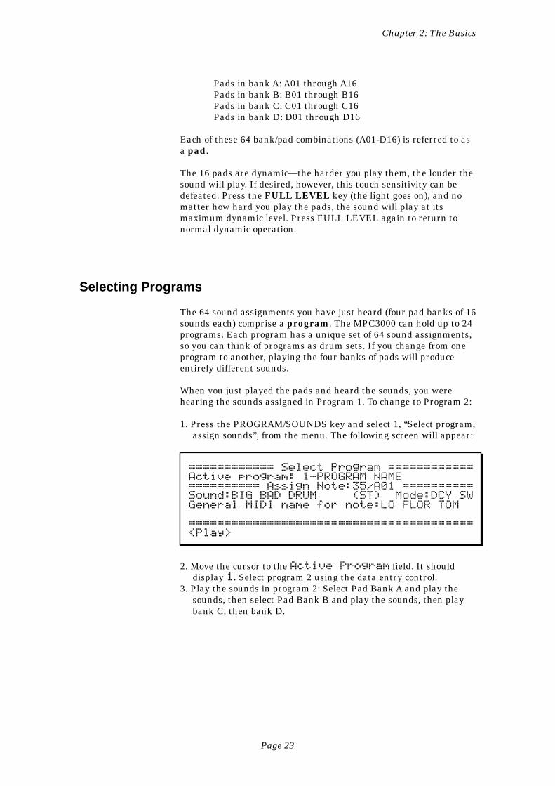
1. Press the PROGRAM/SOUNDS key and select 1, “Select program,assign sounds”, from the menu. The following screen will appear:
============ Select Program ============Active program: 1-PROGRAM NAME========== Assign Note:35/A01 ==========Sound:BIG BAD DRUM (ST) Mode:DCY SWGeneral MIDI name for note:LO FLOR TOM
========================================<Play>
2. Move the cursor to the Active Program field. It shoulddisplay 1. Select program 2 using the data entry control.
3. Play the sounds in program 2: Select Pad Bank A and play thesounds, then select Pad Bank B and play the sounds, then playbank C, then bank D.
Chapter 2: The Basics
Page 24
4. Repeat step 3, except select program 3 and play the sounds.Repeat this procedure to hear the other programs.
5. To return to the Play/Record screen, press MAIN SCREEN.
The Note Variation Slider, ASSIGN and AFTER keys
The Note Variation slider can be used in real time to change thetuning, attack, decay, or filter frequency for a sound played from asingle pad. Once the slider is assigned to single pad and parameter,moving the slider while playing the pad will cause the sound’stuning, attack, decay, or filter frequency to be determined by thecurrent slider position.
Here are some examples of uses of Note Variation:
1. The slider can control decay for a hi-hat sound. This wouldsimulate the action of a drummer’s hi-hat pedal, allowing aunique hi-hat decay time each time the pad is played.
2. The slider can be assigned to tuning for a tom tom sound. Bymoving the slider while playing the tom pad, a wide range of tomtunings is possible.
3. The slider can control filter frequency for a sound containing aresonant filter setting. This would allow each note played to havea different resonant filter frequency, simulating old analogsynthesizer sample and hold filter effects.
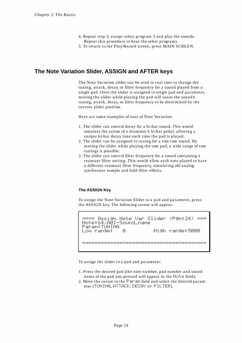
The ASSIGN Key
To assign the Note Variation Slider to a pad and parameter, pressthe ASSIGN key. The following screen will appear:
==== Assign Note Var Slider (Pgm:24) ===Note:64/A01-Sound_nameParam:TUNINGLow range: 0 High range:5000
========================================
To assign the slider to a pad and parameter:
1. Press the desired pad (the note number, pad number and soundname of the pad you pressed will appear in the Note field).
2. Move the cursor to the Param field and select the desired param-eter (TUNING, ATTACK, DECAY or FILTER).
Chapter 2: The Basics
Page 25
3. Press MAIN SCREEN to return to the Play/Record screen.4. Play the selected pad while moving the Note Variation slider.
Each time the pad is played, the selected parameter (tuning,attack, decay or filter) will change according to the slider posi-tion.
Here is additional information about the four fields:
• The Note field:This field contains the note number to which the slider is assigned(35-98). To change the assignment, press a pad. The note number towhich the pad is assigned will instantly appear in the Note field,along with the pad number of the pad you pressed and the name ofthe sound currently assigned to the note number. Alternately, youcan enter the desired note number by direct cursor editing.
• The Param (parameter) field:This field determines which of the four possible parameters theslider will control. The four choices are:
1. TUNING:If selected, the slider alters tuning. This data is added tothe tuning settings used in the program and sound.
2. DECAY:If selected, the slider alters envelope decay time. Thisdata overrides the program’s envelope decay setting.
3. ATTACK:If selected, the slider alters envelope attack time. Thisdata overrides the program’s envelope attack setting.
4. FILTER:If selected, the slider alters filter frequency. This data isadded to the program’s filter frequency setting.
• The Low range and High range fields:These two fields control the range of the slider. The Low range
field determines the parameter value that will be produced whenthe pad is hit while the slider is at the bottom of its travel; theHigh range field determines the parameter value that will beproduced when the pad is hit while the slider is at the top of itstravel. Any position in between produces a proportionate valuebetween these two values. The type of data shown in these fields isdetermined by the parameter selected in the Param field. IfTUNING is selected, these fields contain a signed tuning number(e.g., -120 to +120); if ATTACK or DECAY is selected, they containa millisecond value (0-5000); if FILTER is selected, these fieldscontain a number representing the range of filter frequencies(-50~50).
Chapter 2: The Basics
Page 26
The AFTER key
Note Variation information may be recorded into sequences. Eachdrum note in a sequence contains two pieces of data related to NoteVariation:
1. The Note Variation Parameter: This identifies whichparameter the Note Variation Data will affect (tuning,decay, attack or filter frequency).
2. The Note Variation Data: This is the actual tuning,attack, decay or filter frequency information, represent-ing the position of the slider when the note was recorded.
Normally, the slider only affects new notes—it has no effect on notesplayed back from sequences. However, if the AFTER key is pressed(and the associated light goes on), the slider also overrides the NoteVariation data of any drum notes playing back from sequences, butonly drum notes that are assigned to the same note number (drumpad) and parameter currently selected in the ASSIGN key’s screen.Further, if in Overdub mode while the AFTER key light is on, thesechanges are recorded into the active track.
To return to normal operation, press AFTER again and the light willgo off.
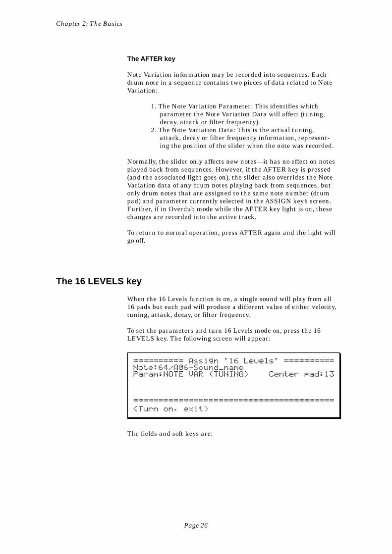
The 16 LEVELS key
When the 16 Levels function is on, a single sound will play from all16 pads but each pad will produce a different value of either velocity,tuning, attack, decay, or filter frequency.
To set the parameters and turn 16 Levels mode on, press the 16LEVELS key. The following screen will appear:
========== Assign '16 Levels' ==========Note:64/A06-Sound_nameParam:NOTE VAR (TUNING) Center pad:13
========================================
<Turn on, exit>
The fields and soft keys are:
Chapter 2: The Basics
Page 27
• The Note field:This field is used to assign the 16 Levels function to one of the 64possible note numbers (35-98). When 16 Levels mode is on, all 16pads will play one sound but at 16 evenly spaced levels of eithervelocity, tuning, decay, attack, or filter frequency. Select a sound bypressing a pad. This will automatically select the note number thatis currently assigned to the selected pad. For convenience, the soundname currently assigned to the selected note number in the activeprogram is displayed.
• The Param field:This is a choice field with two choices:
1. VELOCITY:If this option is selected, and 16 LEVELS mode is on,then the selected note number and sound will play fromall 16 pads, but at 16 fixed velocity levels with the softestlevel on the lower leftmost pad and the loudest level onthe upper rightmost pad.
2. NOTE VAR:If this option is selected, and 16 LEVELS mode is on,then the selected note number and sound will play fromall 16 pads, but at 16 fixed levels of tuning, decay, attack,or filter frequency using the Note Variation data storedwith each drum note in the sequence.
• The Note Variation Parameter field (NOTE VAR (TUNING)(TUNING)(TUNING)(TUNING)(TUNING) in thescreen example above):This field has no label and appears only if NOTE VAR is selectedin the Param field. It is a choice field and is used to determinewhich of the four Note Variation parameters is active. The fourchoices are:
1. (TUNING):If selected, the 16 pads play a single sound but at 16chromatic tunings. The tuning range is controlled by theCenter pad field to the right.
2. (DECAY):If selected, the 16 pads play a single sound but at 16evenly spaced levels of envelope decay. The range of decayvalues is set in the Assign Note Variation screen.
3. (ATTACK):If selected, the 16 pads play a single sound but at 16evenly spaced levels of envelope attack. The range ofattack values is set in the Assign Note Variation screen.
4. (FILTER):If selected, the 16 pads play a single sound but at 16evenly spaced levels of filter frequency. The range of filterfrequency values is set in the Assign Note Variationscreen.
• The Center pad field:This field only appears if the Param field is set to NOTE VAR
and the Note Variation Parameter field is set to (TUNING). It isused to set the tuning range of the 16 pads by selecting which of
Chapter 2: The Basics
Page 28
the 16 pads will play the sound at no tuning change. Regardlessof this center pad, higher numbered pads play higher chromatictunings and lower numbered pads play lower chromatic tunings.In order to limit the entire tuning range of the 16 pads to within+/- one octave, only pads 4 through 13 can be selected. Forexample, if pad 4 is selected, the tuning range is from -30 (-3semitones at pad 1) through 0 (no tuning change at pad 4) to+120 (+12 semitones at pad 16).
To turn the 16 Levels function on:
1. Press the 16 LEVELS key. The 16 Levels screen willappear.
2. Press the pad of the drum you want to use. The Notefield will immediately show the note number assigned tothat pad along with the pad number pressed and thecurrently assigned sound name.
3. Set the Param field to the desired parameter, and, ifNOTE VAR is selected, also set the Note Variation Pa-rameter field to the right.
4. Press the <Turn on, exit> soft key. This will turn thelight above the 16 LEVELS key on and cause the Play/Record screen to be displayed. Now the sound you se-lected will play from all 16 pads, but at 16 fixed levels ofthe parameter you selected.
To turn the 16 Levels function off:
Press the 16 LEVELS key again. The light will go out, indicatingthat normal pad function has returned.
Chapter 3:RecordingSequences
Chapter 3: Recording Sequences
Page 30
How Sequences are Organized
A sequence can be thought of as a segment of multitrack tape ofvariable length. Depending on the sequence contents, it could be atwo-bar repeating drum pattern, an eight-bar verse, or an entire200-bar multitrack composition with time signature and tempochanges. The MPC3000 holds 99 sequences in memory at one time.Normally, only one sequence can play at one time, unless the SimulSequence feature is on, which allows two sequences, or one sequenceand one song, to play simultaneously.
Within each of the 99 sequences are 99 tracks that contain theactual MIDI events. These can be thought of as the tracks on amultitrack tape recorder—they each contain a specific instrument orpiece of the total arrangement, but they all play simultaneously. Forexample, track 1 could be drums, track 2 percussion, track 3 bassguitar, track 4 piano, track 5 horns, track 6 more horns, etc. Eachtrack can be assigned as a Drum track or a MIDI track, but notboth. MIDI tracks contain normal MIDI data recorded from theMIDI input and played out through the MIDI output. Drum tracksare the same as MIDI tracks except for the following:
1. The output of the track plays to the internal drum soundgenerator.
2. You can record drum notes into the track using the frontpanel pads.
3. In sequence editing screens, note events in drum tracksare visually identified and selected not by note numberonly as in MIDI tracks, but also by the pad number andsound name currently assigned to the displayed notenumber.
4. Drum tracks are not affected by the Transpose function.
In order for the sequencer to play external synthesizers, it mustsend its notes out through MIDI on one of the 64 output MIDIchannels (16 channels for each of the 4 MIDI output jacks). On theMPC3000, each track can be independently assigned to output itsnotes through any one or two of these 64 output MIDI channels.
Ticks and Bar.Beat.Tick fields
The timing resolution of the sequencer is 96 divisions per quarternote (96 ppq). Each one of these divisions is called a tick.
In many of the sequence editing screens it is necessary to enter thestart and end of the region to be edited. This is done using a three-part field, called a bar.beat.tick field, containing a bar number,
Chapter 3: Recording Sequences
Page 31
beat number, and tick number. (A beat is the timing value of thelower half of the time signature. For example, in 4/4 time, a beat isone quarter note.) In bar.beat.tick fields, you enter the three partsseparated by decimal points (.), followed by ENTER. For example, toenter bar 1, beat 3 and tick 24, type 1, decimal point, 3, decimalpoint, 24, ENTER. If you only want to enter the bar number, type itfollowed by ENTER—The beat and tick portions will be reset to thestart of the bar.
Chapter 3: Recording Sequences
Page 32
The MAIN SCREEN Key & Play/Record Screen
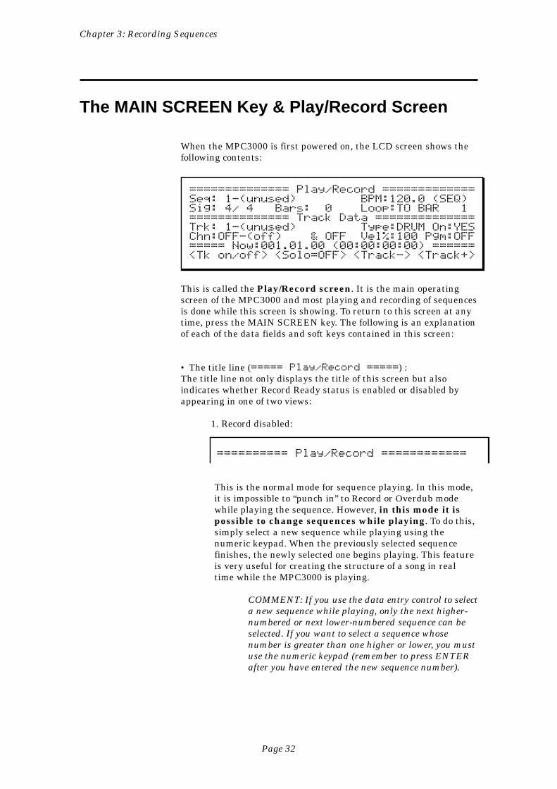
When the MPC3000 is first powered on, the LCD screen shows thefollowing contents:
============== Play/Record =============Seq: 1-(unused) BPM:120.0 (SEQ)Sig: 4/ 4 Bars: 0 Loop:TO BAR 1============== Track Data ==============Trk: 1-(unused) Type:DRUM On:YESChn:OFF-(off) & OFF Vel%:100 Pgm:OFF===== Now:001.01.00 (00:00:00:00) ======<Tk on/off> <Solo=OFF> <Track-> <Track+>
This is called the Play/Record screen. It is the main operatingscreen of the MPC3000 and most playing and recording of sequencesis done while this screen is showing. To return to this screen at anytime, press the MAIN SCREEN key. The following is an explanationof each of the data fields and soft keys contained in this screen:
• The title line (===== Play/Record =====) :The title line not only displays the title of this screen but alsoindicates whether Record Ready status is enabled or disabled byappearing in one of two views:
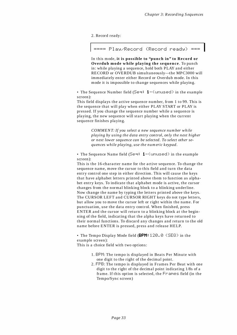
1. Record disabled:
========== Play/Record ============
This is the normal mode for sequence playing. In this mode,it is impossible to “punch in” to Record or Overdub modewhile playing the sequence. However, in this mode it ispossible to change sequences while playing. To do this,simply select a new sequence while playing using thenumeric keypad. When the previously selected sequencefinishes, the newly selected one begins playing. This featureis very useful for creating the structure of a song in realtime while the MPC3000 is playing.
COMMENT: If you use the data entry control to selecta new sequence while playing, only the next higher-numbered or next lower-numbered sequence can beselected. If you want to select a sequence whosenumber is greater than one higher or lower, you mustuse the numeric keypad (remember to press ENTERafter you have entered the new sequence number).
Chapter 3: Recording Sequences
Page 33
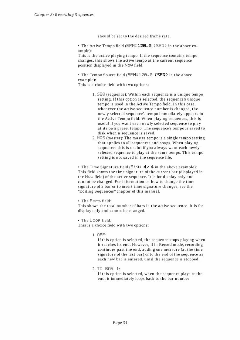
2. Record ready:
==== Play/Record (Record ready) ===
In this mode, it is possible to “punch in” to Record orOverdub mode while playing the sequence. To punchin: while playing a sequence, hold both PLAY and eitherRECORD or OVERDUB simultaneously—the MPC3000 willimmediately enter either Record or Overdub mode. In thismode it is impossible to change sequences while playing.
• The Sequence Number field (Seq: 11111-(unused) in the examplescreen):This field displays the active sequence number, from 1 to 99. This isthe sequence that will play when either PLAY START or PLAY ispressed. If you change the sequence number while a sequence isplaying, the new sequence will start playing when the currentsequence finishes playing.
COMMENT: If you select a new sequence number whileplaying by using the data entry control, only the next higheror next lower sequence can be selected. To select other se-quences while playing, use the numeric keypad.
• The Sequence Name field (Seq: 11111-(unused) in the examplescreen):This is the 16-character name for the active sequence. To change thesequence name, move the cursor to this field and turn the dataentry control one step in either direction. This will cause the keysthat have alphabet letters printed above them to function as alpha-bet entry keys. To indicate that alphabet mode is active, the cursorchanges from the normal blinking block to a blinking underline.Now change the name by typing the letters printed above the keys.The CURSOR LEFT and CURSOR RIGHT keys do not type letters,but allow you to move the cursor left or right within the name. Forpunctuation, use the data entry control. When finished, pressENTER and the cursor will return to a blinking block at the begin-ning of the field, indicating that the alpha keys have returned totheir normal functions. To discard any changes and return to the oldname before ENTER is pressed, press and release HELP.
• The Tempo Display Mode field (BPMBPMBPMBPMBPM:120.0 (SEQ) in theexample screen):This is a choice field with two options:
1. BPM: The tempo is displayed in Beats Per Minute withone digit to the right of the decimal point.
2. FPB: The tempo is displayed in Frames Per Beat with onedigit to the right of the decimal point indicating 1/8s of aframe. If this option is selected, the Frames field (in theTempo/Sync screen)
Chapter 3: Recording Sequences
Page 34
should be set to the desired frame rate.
• The Active Tempo field (BPM:120.0120.0120.0120.0120.0 (SEQ) in the above ex-ample):This is the active playing tempo. If the sequence contains tempochanges, this shows the active tempo at the current sequenceposition displayed in the Now field.
• The Tempo Source field (BPM:120.0 (SEQ)(SEQ)(SEQ)(SEQ)(SEQ) in the aboveexample):This is a choice field with two options:
1. SEQ (sequence): Within each sequence is a unique temposetting. If this option is selected, the sequence’s uniquetempo is used in the Active Tempo field. In this case,whenever the active sequence number is changed, thenewly selected sequence’s tempo immediately appears inthe Active Tempo field. When playing sequences, this isuseful if you want each newly selected sequence to playat its own preset tempo. The sequence’s tempo is saved todisk when a sequence is saved.
2. MAS (master): The master tempo is a single tempo settingthat applies to all sequences and songs. When playingsequences this is useful if you always want each newlyselected sequence to play at the same tempo. This temposetting is not saved in the sequence file.
• The Time Signature field (Sig: 4/4/4/4/4/ 44444 in the above example):This field shows the time signature of the current bar (displayed inthe Now field) of the active sequence. It is for display only andcannot be changed. For information on how to change the timesignature of a bar or to insert time signature changes, see the“Editing Sequences” chapter of this manual.
• The Bars field:This shows the total number of bars in the active sequence. It is fordisplay only and cannot be changed.
• The Loop field:This is a choice field with two options:
1. OFF:If this option is selected, the sequence stops playing whenit reaches its end. However, if in Record mode, recordingcontinues past the end, adding one measure (at the timesignature of the last bar) onto the end of the sequence aseach new bar is entered, until the sequence is stopped.
2. TO BAR 1:If this option is selected, when the sequence plays to theend, it immediately loops back to the bar number
Chapter 3: Recording Sequences
Page 35
displayed to the right of the word BAR. To set thenumber of the bar to which the sequence loops back,move the cursor to the field to the right of the wordBAR and enter the new number.
COMMENT: If the bar to loop to is bar number 1 andthe sequence is in Record mode, the MPC3000 willautomatically switch from Record to Overdub mode atthe moment the sequence loops back—this will preventaccidental erasure of any notes just recorded. In theevent that the bar to loop to is bar number 2 or higherand the sequence is in Record or Overdub mode theMPC3000 will automatically switch to Play mode atthe moment the sequence loops back to the specifiedbar.
The Track Data area (lines 4-6):
• The Active Track field (Trk: 11111-(unused) in the examplescreen):This field displays the active track number within the sequence. Theactive track is the track that, when Record or Overdub mode isentered, will be recorded into from the MIDI keyboard or pads. Also,if the Soft thru field is on (described in the “MIDI Functions”chapter of this manual) and the pads or MIDI keyboard is played,the played notes will be sent out over MIDI in real time using theactive track’s MIDI channel and port assignments. Only one trackcan be active at a time.
• The Track Name field (Trk: 1-(unused)(unused)(unused)(unused)(unused) in the examplescreen)This field has no on-screen title, but is the 16-character name of theactive track, and is located directly to the right of the active tracknumber. It is changed in the same manner as the sequence name,detailed above.
• The Type field:This is a choice field with two options—MIDI and DRUM:
1. MIDI: Select this option if you want to record normalnon-drum MIDI data from an external MIDI keyboardinto the selected track. MIDI tracks do not use theinternal sound generator or pads.
2. DRUM: Select this option if you want to record drum datainto the selected track. Drum tracks are the same asMIDI tracks except for the following:
A. The output of the track plays to the internaldrum sound generator.
B. You can record drum notes into the track usingthe front panel pads.
C. In sequence editing screens, note events indrum tracks are visually identified and
Chapter 3: Recording Sequences
Page 36
selected not by note number only as in MIDItracks, but also by the pad number and soundname currently assigned to the displayed notenumber.
D. Drum tracks are not affected by the Transposefunction.
• The Track On/Off field (On:YESYESYESYESYES in the example screen):This choice field turns the output of the active track on (YES) or off(NO). Pressing SOFT KEY 1 toggles the field’s state between YESand NO.
• The MIDI Channel/Port fields (Chn:OFFOFFOFFOFFOFF-(off) in the examplescreen):There are actually two fields here, which together are used todetermine which MIDI channel and MIDI output port the activetrack will output its data to. The to fields are:
1. The MIDI Channel field (Chn: 11111A-(off)):This field determines which of the 16 MIDI channels theactive track will play through. If you don’t want the trackto play through any MIDI channels, select 0 and the wordOFF will appear.
2. The MIDI Port field (Chn: 1AAAAA-(off)):This choice field determines which of the four MIDIoutput ports (A, B, C, or D) the active track will playthrough. (If OFF is selected in the MIDI channel field tothe left, this field can’t be seen.)
COMMENT: If OFF is displayed in this field (no MIDIoutput assignment) and you want to select a MIDI channel orport, first move the cursor to the letter “O” of OFF and turnthe data entry control one step to the right.
• The MIDI Channel/Port Name field (Chn:OFF-(off)(off)(off)(off)(off) in theexample screen):This is the eight-character name for the currently selected MIDIoutput channel/port combination. This would commonly contain thename of the synthesizer that is being played from the displayedMIDI channel/port combination. There are 64 names—one for eachof the 64 output MIDI channel/port combinations. The name ischanged in exactly the same way as the sequence name field.
COMMENT: These 64 names are intended to be used toidentify the MIDI devices that are externally connected—notthe data contained in the track. For this reason, they are notsaved within sequence files or ALL files. They are, however,retained in memory after power is removed and are alsosaved within Parameter files.
• The Auxiliary MIDI Channel/Port fields (& OFF in the examplescreen):These two fields have exactly the same function and operation asthe MIDI Channel/Port fields shown to the left. These two
Chapter 3: Recording Sequences
Page 37
fields allow the active track to play simultaneously through anadditional channel/port combination. If no additional output chan-nel/port is desired, select OFF here.
• The Velocity% field (Vel%:100100100100100 in the example screen):This is an overall output volume control for active track. However,unlike a normal volume control, this function actually scales thevelocities of all notes that play from the track in real time, acting asa real-time dynamics control. The range is from 0 to 200%. Valuesfrom 0 to 99 reduce velocities; values from 101 to 200 increase them.Select 100 for no effect.
• The Program Number field (Pgm:OFF ):This field permits a MIDI program number (1-128) to be assigned tothe active track. To select no program assignment for the activetrack, enter a 0 in this field and OFF will be displayed. Whenever anew sequence is selected, if any of the sequence’s tracks containprogram number assignments, those program numbers will beimmediately sent out over the track’s assigned MIDI channel/port(not the auxiliary MIDI channel/port) to the external synthesizer,causing it to change to the assigned program number. This way, allexternal synthesizers are immediately changed to the correctprogram numbers by merely selecting the sequence. If a track’sType field is set to DRUM, the assigned program number willchange the internal sound generator’s active program number.
COMMENT: It is also possible to record MIDI programchange events at any location within a track, either in realtime or in Step Edit mode. (See the “Step Edit” section inthe “Editing Sequences” chapter of this manual for moredetails about this.) It is important to note that if one of theseprogram change events is inserted mid-sequence and theportion of the sequence containing the change is played(causing the external synthesizer to change to the new pro-gram), the original program number (as set up in the Pro-gram Number field) will not be re-sent over MIDI until thesequence is reselected in the Sequence Number field. Simplyrestarting the sequence will not implement the programchange. If the MPC3000 did send out all assigned programnumbers whenever PLAY START were pressed, this problemwould be corrected, but there would also be a brief delay atthe start of the sequence because the external synthesizersmust take time to change their program data. If you do wanta program change to be sent out whenever PLAY START ispressed, it is better to insert a MIDI Program Change eventat the start of the track, using Step Edit.
• The Now field (Now:001.01.00001.01.00001.01.00001.01.00001.01.00 (00:00:00:0000:00:00:0000:00:00:0000:00:00:0000:00:00:00) in theexample screen):This field displays the current position within the sequence. The leftside of this field shows the current position in musical terms—as athree-part number separated by decimal points.
Chapter 3: Recording Sequences
Page 38
The first part is the bar number; the second is the beat numberwithin the bar (the beat is equal to the denominator of the timesignature); and the third is the tick number within the beat (thereare 96 ticks to a quarter note). Bars and beats start at 1; ticks startat 0.
To the right of the above-described bar.beat.tick number is anotherfour-part number, displayed in parentheses. This field shows thecurrent position of the sequence as a function of elapsed time fromthe beginning of the sequence, in hours, minutes, seconds, andframes. However, the number displayed when the sequence is set tothe start is not necessarily 00:00:00:00, but rather is equal to theSMPTE start time. SMPTE operation is described in the chapter 10:“Syncing to Tape and Other Devices”.
This field is for display only and cannot be edited directly with thecursor. It is normally changed by using the REWIND, FAST FOR-WARD and LOCATE keys, described in the “Play/Record Keys”section of this chapter. These fields change in real time while thesequence plays. However, the right-most part of each field—the ticksand frames parts—are replaced with two dashes (—) while playingbecause they would otherwise change too quickly to be useful.
The four soft keys are:
• The <Tk on/off> soft key:Pressing this soft key toggles the Track On/Off field between YESand NO.
• The <Solo=OFF> soft key:Pressing this soft key turns solo mode ON or OFF. If set to ON, onlythe active track is heard and all other tracks are temporarily muted.The text of the soft key indicates whether solo mode is ON or OFF.
• The <Track-> soft key:Pressing this soft key decrements the active track number by one.
• The <Track+> soft key:Pressing this soft key increments the active track number by one.
Chapter 3: Recording Sequences
Page 39
The Play/Record Keys
These ten keys operate similarly to the transport keys on a taperecorder, with some very useful additions:
• The PLAY START key:This key causes the active sequence to begin playing from the startof bar 1.
• The PLAY key:This key causes the sequence to begin playing from the currentposition displayed in the Now field in the Play/Record screen.
• The STOP key:This key causes the sequence to stop playing.
• The OVERDUB key:This key, when held down while PLAY is pressed, causes Overdubmode to be entered, in which new notes can be recorded into theactive track without erasing existing notes. While Overdub mode isactive, the light above the OVERDUB key is on.
It is also possible to punch-in to Overdub mode while playing. To dothis:
1. The MPC3000 must be in Record Ready mode. (The topline of the Play/Record screen must display the wordsPlay/Record (Record ready).) If not, simplypress and release the RECORD or OVERDUB key oncewhile the sequence is stopped.
2. While the sequence is playing, simultaneously press theOVERDUB and PLAY keys. Overdub mode is now active,indicated by the light above the OVERDUB key.
To punch-out of Overdub mode, simply press the OVERDUB keyonce, and the light above the OVERDUB key will turn off.
COMMENT: If Overdub mode is entered while the sequenceis set to loop to a higher-numbered bar than bar number1,Overdub mode will automatically be turned off at the mo-ment the sequence reaches the end and starts to loop.
• The RECORD key:This key, when held down while PLAY is pressed, causes Recordmode to be entered, in which new notes can be recorded into theactive track while existing notes are erased, just as with a taperecorder. While Record mode is active, the light above the RECORDkey is on.
Chapter 3: Recording Sequences
Page 40
It is also possible to punch-in to Record mode while playing. To dothis:
1. The MPC3000 must be in Record Ready mode. (The topline of the Play/Record screen must display the wordsPlay/Record (Record ready).) If not, simplypress and release the RECORD or OVERDUB key oncewhile the sequence is stopped.
2. While the sequence is playing, simultaneously press theRECORD and PLAY keys. Record mode is now active, asindicated by the light above the RECORD key.
To punch-out of Record mode, simply press the RECORD key once,and the light above the RECORD key will turn off.
COMMENT: If Record mode is entered while the sequence isset to loop to bar number1 (or a portion of the sequence islooped with the Edit Loop function), Record mode automati-cally switches to Overdub mode at the moment the sequencereaches the end and starts to loop. This prevents accidentalerasure of any data that were recorded on the previous passthrough the loop. If, however, Record mode is entered whilethe sequence is set to loop to a higher-numbered bar than bar1, Record mode will automatically be turned off at themoment the sequence reaches the end and starts to loop.
COMMENT: If an empty sequence is selected (the sequencename field shows “unused”), and either RECORD or OVER-DUB is pressed, the sequence will instantly be initializedusing the settings in the Initialize Sequence screen. Thisfunction is normally accessed by pressing the ERASE keyand selecting SOFT KEY 2.
• The REWIND [<<] and FAST FORWARD [>>] keys:Use these two keys to change the current position within the se-quence to either the previous or next bar boundary. The actions ofthese keys repeat when they are held.
• The REWIND [<] and FAST FORWARD [>] keys:Use these two keys to move the current position within the sequenceto either the previous or next note boundary, as determined by thevalue in the Note Value field of the Timing Correct screen(normally set to 1/16 NOTE). To change the amount of movement,simply change the setting in this data field. The actions of thesekeys repeat when they are held.
While the Step Edit function is active, it is possible to set these keysto an alternate function—to search to the previous or next event of aspecific type within the track. To learn how to do this, see the “Step
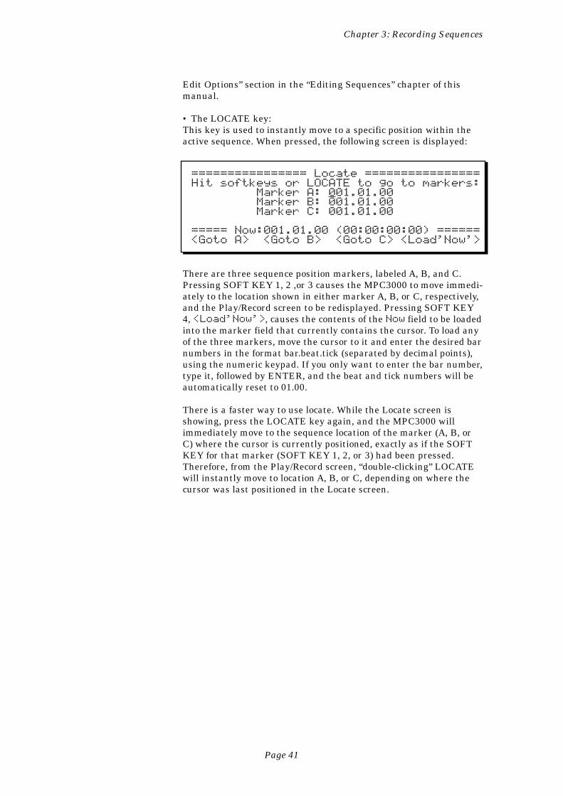
Chapter 3: Recording Sequences
Page 41
Edit Options” section in the “Editing Sequences” chapter of thismanual.
• The LOCATE key:This key is used to instantly move to a specific position within theactive sequence. When pressed, the following screen is displayed:
================ Locate ================Hit softkeys or LOCATE to go to markers: Marker A: 001.01.00 Marker B: 001.01.00 Marker C: 001.01.00
===== Now:001.01.00 (00:00:00:00) ======<Goto A> <Goto B> <Goto C> <Load'Now'>
There are three sequence position markers, labeled A, B, and C.Pressing SOFT KEY 1, 2 ,or 3 causes the MPC3000 to move immedi-ately to the location shown in either marker A, B, or C, respectively,and the Play/Record screen to be redisplayed. Pressing SOFT KEY4, <Load'Now'>, causes the contents of the Now field to be loadedinto the marker field that currently contains the cursor. To load anyof the three markers, move the cursor to it and enter the desired barnumbers in the format bar.beat.tick (separated by decimal points),using the numeric keypad. If you only want to enter the bar number,type it, followed by ENTER, and the beat and tick numbers will beautomatically reset to 01.00.
There is a faster way to use locate. While the Locate screen isshowing, press the LOCATE key again, and the MPC3000 willimmediately move to the sequence location of the marker (A, B, orC) where the cursor is currently positioned, exactly as if the SOFTKEY for that marker (SOFT KEY 1, 2, or 3) had been pressed.Therefore, from the Play/Record screen, “double-clicking” LOCATEwill instantly move to location A, B, or C, depending on where thecursor was last positioned in the Locate screen.
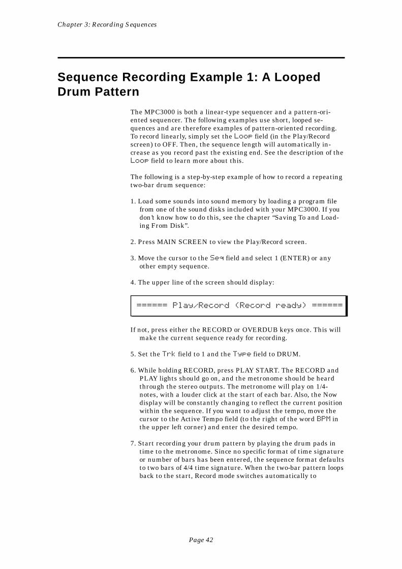
Chapter 3: Recording Sequences
Page 42
Sequence Recording Example 1: A LoopedDrum Pattern
The MPC3000 is both a linear-type sequencer and a pattern-ori-ented sequencer. The following examples use short, looped se-quences and are therefore examples of pattern-oriented recording.To record linearly, simply set the Loop field (in the Play/Recordscreen) to OFF. Then, the sequence length will automatically in-crease as you record past the existing end. See the description of theLoop field to learn more about this.
The following is a step-by-step example of how to record a repeatingtwo-bar drum sequence:
1. Load some sounds into sound memory by loading a program filefrom one of the sound disks included with your MPC3000. If youdon’t know how to do this, see the chapter “Saving To and Load-ing From Disk”.
2. Press MAIN SCREEN to view the Play/Record screen.
3. Move the cursor to the Seq field and select 1 (ENTER) or anyother empty sequence.
4. The upper line of the screen should display:
====== Play/Record (Record ready) ======
If not, press either the RECORD or OVERDUB keys once. This willmake the current sequence ready for recording.
5. Set the Trk field to 1 and the Type field to DRUM.
6. While holding RECORD, press PLAY START. The RECORD andPLAY lights should go on, and the metronome should be heardthrough the stereo outputs. The metronome will play on 1/4-notes, with a louder click at the start of each bar. Also, the Nowdisplay will be constantly changing to reflect the current positionwithin the sequence. If you want to adjust the tempo, move thecursor to the Active Tempo field (to the right of the word BPM inthe upper left corner) and enter the desired tempo.
7. Start recording your drum pattern by playing the drum pads intime to the metronome. Since no specific format of time signatureor number of bars has been entered, the sequence format defaultsto two bars of 4/4 time signature. When the two-bar pattern loopsback to the start, Record mode switches automatically to
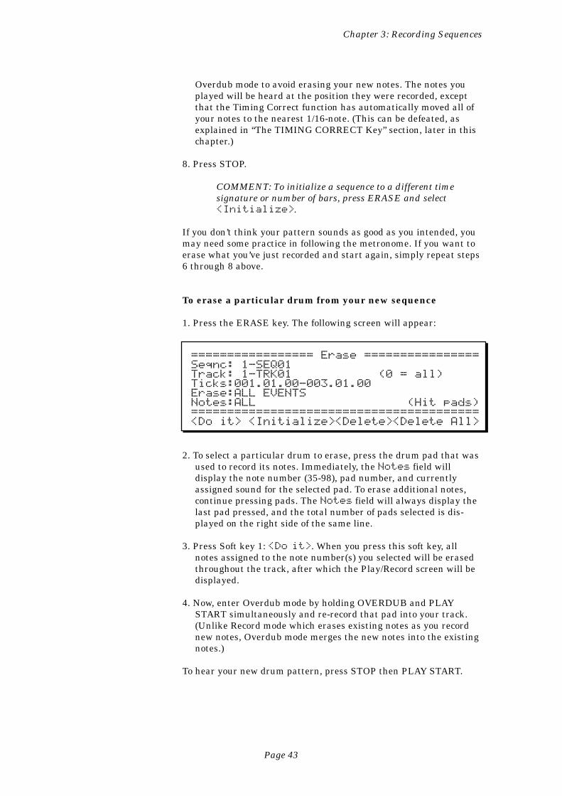
Chapter 3: Recording Sequences
Page 43
Overdub mode to avoid erasing your new notes. The notes youplayed will be heard at the position they were recorded, exceptthat the Timing Correct function has automatically moved all ofyour notes to the nearest 1/16-note. (This can be defeated, asexplained in “The TIMING CORRECT Key” section, later in thischapter.)
8. Press STOP.
COMMENT: To initialize a sequence to a different timesignature or number of bars, press ERASE and select<Initialize>.
If you don’t think your pattern sounds as good as you intended, youmay need some practice in following the metronome. If you want toerase what you’ve just recorded and start again, simply repeat steps6 through 8 above.
To erase a particular drum from your new sequence
1. Press the ERASE key. The following screen will appear:
================= Erase ================Seqnc: 1-SEQ01Track: 1-TRK01 (0 = all)Ticks:001.01.00-003.01.00Erase:ALL EVENTSNotes:ALL (Hit pads)========================================<Do it> <Initialize><Delete><Delete All>
2. To select a particular drum to erase, press the drum pad that wasused to record its notes. Immediately, the Notes field willdisplay the note number (35-98), pad number, and currentlyassigned sound for the selected pad. To erase additional notes,continue pressing pads. The Notes field will always display thelast pad pressed, and the total number of pads selected is dis-played on the right side of the same line.
3. Press Soft key 1: <Do it>. When you press this soft key, allnotes assigned to the note number(s) you selected will be erasedthroughout the track, after which the Play/Record screen will bedisplayed.
4. Now, enter Overdub mode by holding OVERDUB and PLAYSTART simultaneously and re-record that pad into your track.(Unlike Record mode which erases existing notes as you recordnew notes, Overdub mode merges the new notes into the existingnotes.)
To hear your new drum pattern, press STOP then PLAY START.
Chapter 3: Recording Sequences
Page 44
Sequence Recording Example 2: A MultitrackSequence
The following is a step-by-step example of recording a multitracksequence with a format of 4 bars of 4/4 time, containing the follow-ing tracks:
Track 1: DrumsTrack 2: PercussionTrack 3: BassTrack 4: Piano
First, set up the instruments:
1. Using the connection diagram in the “Hooking Up Your System”section (in the “Basics” chapter) as a guideline, connect the MIDIOut connector of a MIDI keyboard to MIDI Input 1 of theMPC3000 and connect MIDI Output A of the MPC3000 to amultitimbral synthesizer that is set to play both bass and pianosounds simultaneously. (Alternately, you could connect twosynthesizers in a daisy chain, with the MIDI thru connector ofthe first synthesizer connecting to the MIDI input of the second.)
2. Set up the synthesizer(s) so that a bass sound plays from MIDIchannel 1A and a piano sound plays from MIDI channel 2A. Ifyou are using a single integrated keyboard, set Local Control onyour keyboard to OFF during this tutorial.
3. If no sounds are loaded into sound memory, load a program filefrom one of the sound disks included with your MPC3000. If youdon’t know how to do this, see the chapter “Saving To and Load-ing From Disk”.
4. The Play/Record screen should be showing. If not, press MAINSCREEN.
5. The upper line of the screen should display Play/Record(Record ready). If not, press either the RECORD or OVER-DUB key once. This will make the current sequence ready forrecording.
Next, initialize the sequence to 4 bars of 4/4 time:
1. Move the cursor to the Seq field and select 2 (ENTER) or anyother sequence that is currently empty.
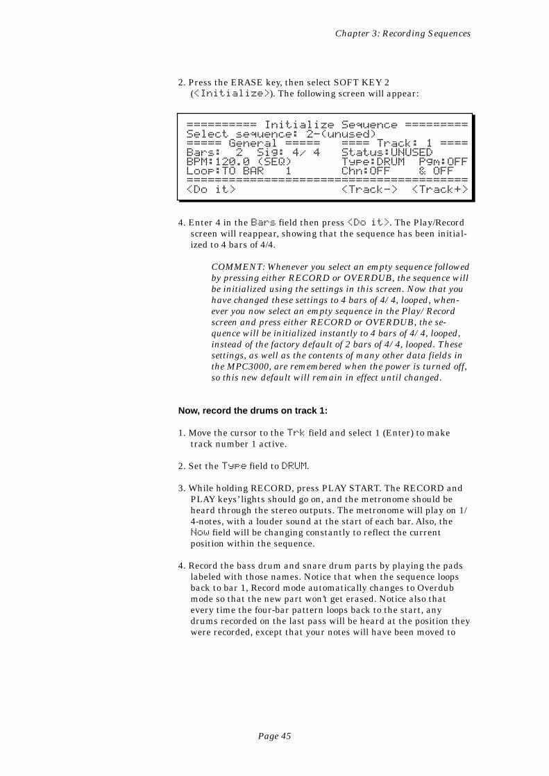
Chapter 3: Recording Sequences
Page 45
2. Press the ERASE key, then select SOFT KEY 2(<Initialize>). The following screen will appear:
========== Initialize Sequence =========Select sequence: 2-(unused)===== General ===== ==== Track: 1 ====Bars: 2 Sig: 4/ 4 Status:UNUSEDBPM:120.0 (SEQ) Type:DRUM Pgm:OFFLoop:TO BAR 1 Chn:OFF & OFF========================================<Do it> <Track-> <Track+>
4. Enter 4 in the Bars field then press <Do it>. The Play/Recordscreen will reappear, showing that the sequence has been initial-ized to 4 bars of 4/4.
COMMENT: Whenever you select an empty sequence followedby pressing either RECORD or OVERDUB, the sequence willbe initialized using the settings in this screen. Now that youhave changed these settings to 4 bars of 4/4, looped, when-ever you now select an empty sequence in the Play/Recordscreen and press either RECORD or OVERDUB, the se-quence will be initialized instantly to 4 bars of 4/4, looped,instead of the factory default of 2 bars of 4/4, looped. Thesesettings, as well as the contents of many other data fields inthe MPC3000, are remembered when the power is turned off,so this new default will remain in effect until changed.
Now, record the drums on track 1:
1. Move the cursor to the Trk field and select 1 (Enter) to maketrack number 1 active.
2. Set the Type field to DRUM.
3. While holding RECORD, press PLAY START. The RECORD andPLAY keys’ lights should go on, and the metronome should beheard through the stereo outputs. The metronome will play on 1/4-notes, with a louder sound at the start of each bar. Also, theNow field will be changing constantly to reflect the currentposition within the sequence.
4. Record the bass drum and snare drum parts by playing the padslabeled with those names. Notice that when the sequence loopsback to bar 1, Record mode automatically changes to Overdubmode so that the new part won’t get erased. Notice also thatevery time the four-bar pattern loops back to the start, anydrums recorded on the last pass will be heard at the position theywere recorded, except that your notes will have been moved to
Chapter 3: Recording Sequences
Page 46
the nearest value specified in the Timing Correct screen (in thiscase, 1/16-note).
5. Without stopping the sequence, record a 1/16-note hi-hat part bysimultaneously holding the TIMING CORRECT key and theHIHAT CLOSED pad, varying the pressure on the pad as thesequence plays. After four bars, release both the key and the pad.Notice that closed hi-hats have now been recorded on all 1/16-notes. This feature is called note repeat and is described furtherin the “Timing Correct” section, later in this chapter. If at anytime you want to erase what you’ve recorded and start over, goback to step 3.
If you accidentally played one or two wrong notes, you can erasethem without affecting any other notes by following these steps:
A) While still in Overdub mode, hold down the ERASE key.B) Just before the wrong notes are about to play, hold that
drum’s pad down, then quickly release it as soon as thewrong notes have passed.
C) Release the ERASE key. The wrong notes have now beenpermanently erased from the sequence.
6. Press STOP.
Next, overdub the percussion part on track 2:
1. With the Play/Record screen showing, move the cursor to the Trkfield and select 2.
2. Set the Type field to DRUM.
3. Enter Record mode again by holding RECORD and pressingPLAY START. You will hear the drum part you just recorded ontrack 1. Don’t worry about erasing it: since track 2 is now theactive track, all recording and erasing occurs only on track 2.
4. Record the percussion part by playing pads assigned to percussioninstruments. (Try Pad Bank B.) Keep adding drums until yourpercussion part is complete.
5. If any mistakes were made, use either of the two erase methodsdescribed above.
Next, overdub the bass part on track 3:
1. With the Play/Record screen showing, move the cursor to the Trkfield and select 3 to make track 3 active.
Chapter 3: Recording Sequences
Page 47
2. Set the Type field to MIDI, indicating that this track will notplay the internal drum sounds.
3. Set the Chn field to 1A, indicating that track 3 will play throughMIDI channel 1 and MIDI output port A. The Chn field is actu-ally two fields—move the cursor to the position indicated by theunderline below and select 1:
Chn:OFF becomes—> Chn: 1A
4. If you play the MIDI keyboard now, the synthesizer that is set toreceive on MIDI channel 1 should play a bass sound. If not, checkthe previous steps and your MIDI hookup.
5. Press the COUNT IN key—the light will go on. This will causethe metronome to play one bar before the sequence plays to cueyou to start playing. By default, the count in will only play beforeyou start recording or overdubbing but not before playing. Thiscan be changed by pressing the OTHER key and changing thesetting of the Count in field in the screen that appears.
6. Enter RECORD MODE by holding RECORD and pressing PLAYSTART.
7. Once the COUNT IN bar has passed, record your bass part intime to the drums and percussion parts.
8. Press the COUNT IN key again to turn it off.
9. If you make a mistake while recording, you can correct it bypunching in the new note:
A) Press the REWIND keys [<] or [<<] until the Now fieldshows a location about one bar before the mistake.
B) Press PLAY (not PLAY START). The sequence will startplaying from the position shown in the Now field.
C) Just before the wrong note plays, press RECORD andPLAY simultaneously to enter Record mode (in whichexisting notes are erased while new notes are recorded)then play the correct note. You can now either punch outby pressing RECORD again or continue recording fromthat point. Don’t worry: when the sequence loops back tobar 1, it will automatically switch from Record to Over-dub mode so that those notes in the earlier part of thesequence won’t be erased.
Now, overdub the piano part on track 4:
1. Move the cursor to the Trk field and select 4 to make track 4active.
Chapter 3: Recording Sequences
Page 48
2. Set the Type field to MIDI, indicating that this track will notplay the internal drum sounds.
3. Set the Chn field to 2A, indicating that track 4 will play throughMIDI channel 2 and MIDI output port A.
4. If you play the MIDI keyboard now, the synthesizer that is set toreceive on MIDI channel 2 and port A should play a piano sound.If not, check the previous steps and your MIDI hookup.
5. Enter Record mode by holding RECORD and pressing PLAYSTART.
6. Record your piano part in time to the drums, percussion and bassparts.
7. Press STOP.
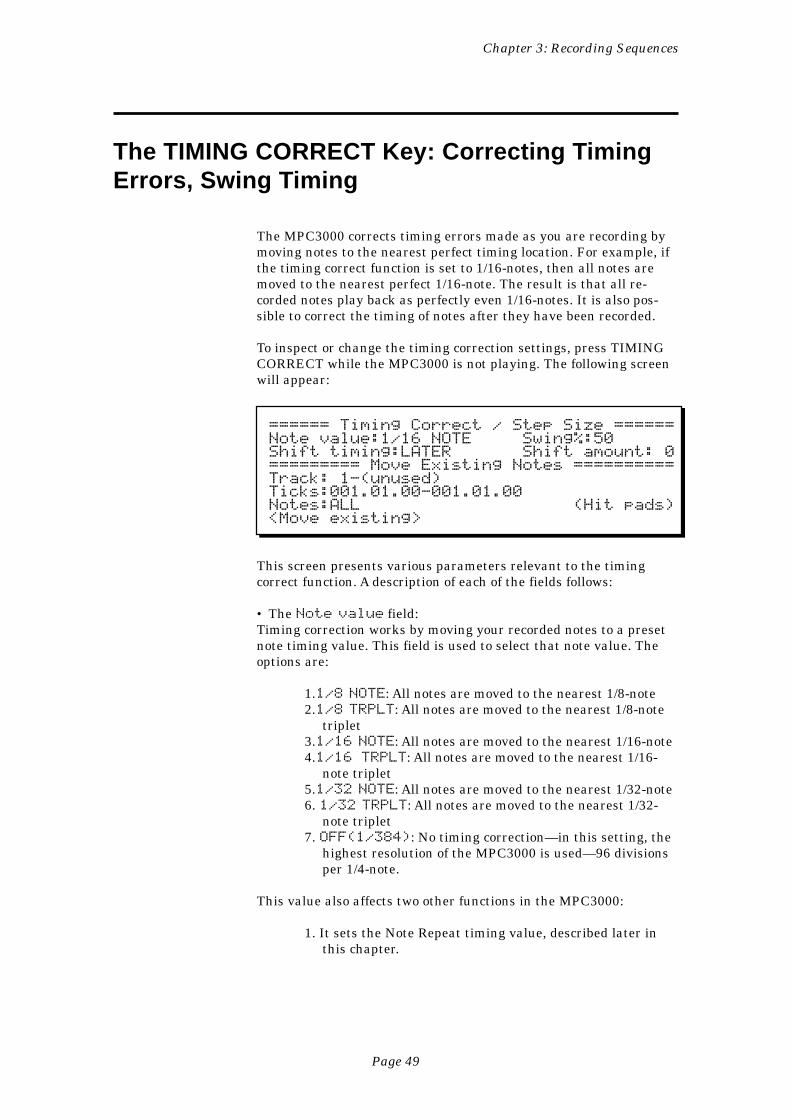
Chapter 3: Recording Sequences
Page 49
The TIMING CORRECT Key: Correcting TimingErrors, Swing Timing
The MPC3000 corrects timing errors made as you are recording bymoving notes to the nearest perfect timing location. For example, ifthe timing correct function is set to 1/16-notes, then all notes aremoved to the nearest perfect 1/16-note. The result is that all re-corded notes play back as perfectly even 1/16-notes. It is also pos-sible to correct the timing of notes after they have been recorded.
To inspect or change the timing correction settings, press TIMINGCORRECT while the MPC3000 is not playing. The following screenwill appear:
====== Timing Correct / Step Size ======Note value:1/16 NOTE Swing%:50Shift timing:LATER Shift amount: 0========= Move Existing Notes ==========Track: 1-(unused)Ticks:001.01.00-001.01.00Notes:ALL (Hit pads)<Move existing>
This screen presents various parameters relevant to the timingcorrect function. A description of each of the fields follows:
• The Note value field:Timing correction works by moving your recorded notes to a presetnote timing value. This field is used to select that note value. Theoptions are:
1.1/8 NOTE: All notes are moved to the nearest 1/8-note2.1/8 TRPLT: All notes are moved to the nearest 1/8-note
triplet3.1/16 NOTE: All notes are moved to the nearest 1/16-note4.1/16 TRPLT: All notes are moved to the nearest 1/16-
note triplet5.1/32 NOTE: All notes are moved to the nearest 1/32-note6. 1/32 TRPLT: All notes are moved to the nearest 1/32-
note triplet7. OFF(1/384): No timing correction—in this setting, the
highest resolution of the MPC3000 is used—96 divisionsper 1/4-note.
This value also affects two other functions in the MPC3000:
1. It sets the Note Repeat timing value, described later inthis chapter.
Chapter 3: Recording Sequences
Page 50
2. It sets the amount by which the current sequence positionwill change when either the REWIND [<] or FASTFORWARD [>] key is pressed.
• The Swing% field:This field only appears if the Note Value field is set to either 1/16- or1/8-notes. The swing feature is a variation of timing correction.Whereas normal timing correction moves your notes to perfect 1/16-or 1/8-note intervals, the swing feature moves your notes to swing-timing intervals. The amount of swing is measured as a percentageof time given to the first note in each pair of 1/16- or 1/8-notes. Therange of values is from 50% to 75%. For example:
• A swing setting of 50% gives perfectly even timing with noswing effect; the first and second notes of each pair of 1/16-or 1/8-notes have equal (50%) timing.• A swing setting of 66% indicates a technically perfectswing; the first note of each pair of 1/8 or 1/16 notes has atiming value of twice that of the second note, giving theeffect of 1/16- or 1/8-note triplets where the middle note ofeach triplet is silent.• A swing setting of 75% is the highest swing setting; thefirst note of each pair of 1/8 or 1/16 notes has a timing valueof three times that of the second note. This creates a veryexaggerated swing timing.
A very important use of the swing feature is to add a human rhythmfeel to the timing of your music. Here are a couple of useful settingsto experiment with:
• Note Value = 1/16, Swing = 54%, Tempo = 100 BPM:While not enough swing for a true swing feel, this smallamount of swing timing removes the stiffness from perfect 1/16-note timing and is especially useful on drum sequencesusing 1/16-note hi-hats.• Note Value = 1/16, Swing = 62%, Tempo = 100 BPM:This creates an 1/16-note swing feel that could be describedas more relaxed than a perfect triplet swing (66%).
As with timing correction, swing moves your notes in real time asthey are recorded into the sequence, so your notes are instantlyplayed back with the specified shift. Also, as with timing correction,this effect can be used on existing sequence data by using SOFTKEY 1 (<Move existing>).
• The Shift timing and Shift amount fields:These two fields work in conjunction with the Note value andSwing% fields to move your notes to shifted timing locations. TheShift timing field sets the direction of shift (EARLIER orLATER) and the Shift amount field sets the amount of timingshift in ticks (1/96 of a 1/4-note). For example, in order to compen-sate for the slow attack time of a particular synthesizer, you might
Chapter 3: Recording Sequences
Page 51
set these two fields to EARLY, 1 tick. This would cause all new notesto be recorded onto 1/16-notes but at 1 tick earlier than normal.
COMMENT: It is not possible for this function to shift thetiming of notes without also correcting their timing. This alsomeans that the range of shift depends on the current Notevalue field’s setting. For example, if the Note valuefield is set to 1/16-notes, the maximum shift amount is 11ticks, or slightly less than 1/2 of one 1/16-note; if the Notevalue field is set to 1/32 notes, the maximum shift amountis 5 ticks, or slightly less than 1/2 of one 1/32 note; and ifthe Note Value field is set to OFF(1/384), the Shiftamount is fixed at 0, meaning that no shift is possible sincetiming correction is not being used. If you wish to shift thetiming of a track independently of the timing correctionfunction, use the Shift Timing function, accessed by pressingthe SEQ EDIT key.
COMMENT: If the Shift Timing function is set to shiftnotes early and one or more notes exist at the start of thesequence, these starting notes will be deleted when the<Move existing> operation is performed, becausethere is no space before the start of the sequence for themto be moved to. To avoid this problem, insert a blank barbefore bar 1 of the sequence before performing the shiftoperation, then be sure to include this extra bar within therange of bars to be shifted. This way, the notes that wouldhave been lost will now be moved onto this newly insertedbar.
• The Ticks fields:These two fields are used to specify the region of the sequence thatwill be altered when the <Move existing> soft key is pressed.These are bar.beat.tick fields—the region starts at the locationentered in the leftmost field and ends one tick before the locationentered in the rightmost field.
• The Track field:This field is only used in conjunction with the <Move existing>soft key. It is used to specify the track number that is to be altered.Entering a 0 indicates all tracks will be altered.
• The <Move existing> soft key:Normally, the timing correct function operates in real time, correct-ing notes before they are recorded into the sequence. It is alsopossible to correct the timing (or add swing or shift the timing) of anexisting sequence. Pressing this soft key will cause the region of theactive sequence specified by the Ticks and Track fields to becorrected according to the settings of the Note value, Swing%,Shift timing and Shift amount fields.
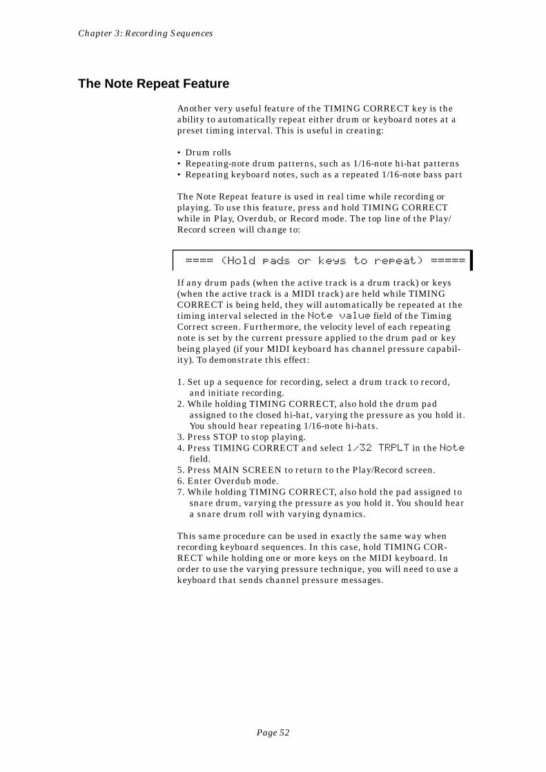
Chapter 3: Recording Sequences
Page 52
The Note Repeat Feature
Another very useful feature of the TIMING CORRECT key is theability to automatically repeat either drum or keyboard notes at apreset timing interval. This is useful in creating:
• Drum rolls• Repeating-note drum patterns, such as 1/16-note hi-hat patterns• Repeating keyboard notes, such as a repeated 1/16-note bass part
The Note Repeat feature is used in real time while recording orplaying. To use this feature, press and hold TIMING CORRECTwhile in Play, Overdub, or Record mode. The top line of the Play/Record screen will change to:
==== (Hold pads or keys to repeat) =====
If any drum pads (when the active track is a drum track) or keys(when the active track is a MIDI track) are held while TIMINGCORRECT is being held, they will automatically be repeated at thetiming interval selected in the Note value field of the TimingCorrect screen. Furthermore, the velocity level of each repeatingnote is set by the current pressure applied to the drum pad or keybeing played (if your MIDI keyboard has channel pressure capabil-ity). To demonstrate this effect:
1. Set up a sequence for recording, select a drum track to record,and initiate recording.
2. While holding TIMING CORRECT, also hold the drum padassigned to the closed hi-hat, varying the pressure as you hold it.You should hear repeating 1/16-note hi-hats.
3. Press STOP to stop playing.4. Press TIMING CORRECT and select 1/32 TRPLT in the Note
field.5. Press MAIN SCREEN to return to the Play/Record screen.6. Enter Overdub mode.7. While holding TIMING CORRECT, also hold the pad assigned to
snare drum, varying the pressure as you hold it. You should heara snare drum roll with varying dynamics.
This same procedure can be used in exactly the same way whenrecording keyboard sequences. In this case, hold TIMING COR-RECT while holding one or more keys on the MIDI keyboard. Inorder to use the varying pressure technique, you will need to use akeyboard that sends channel pressure messages.
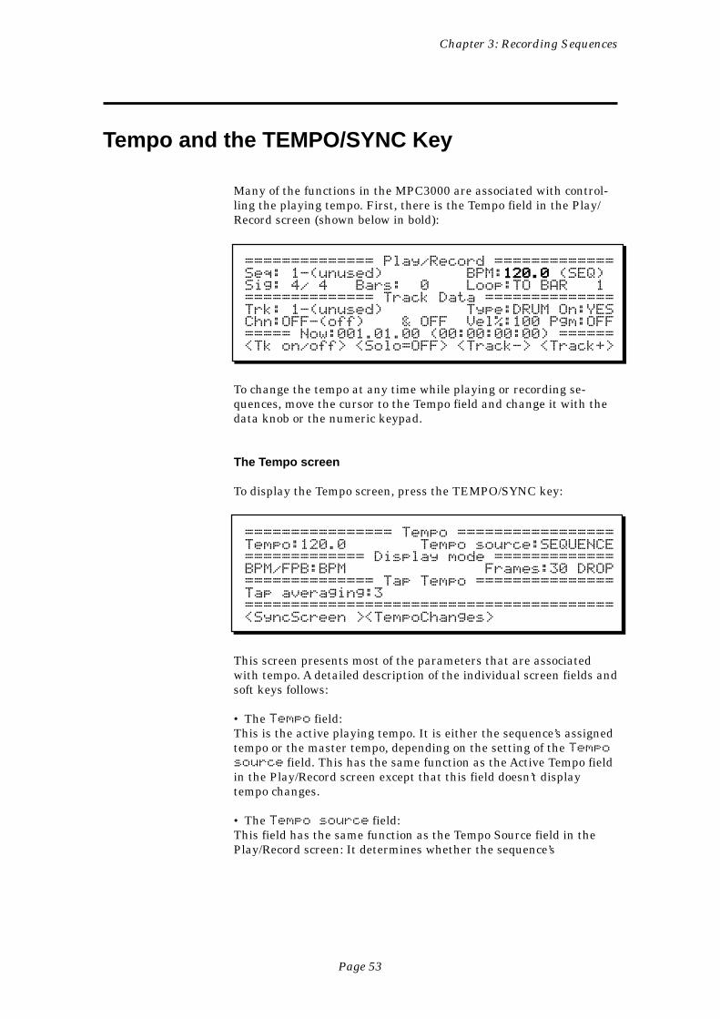
Chapter 3: Recording Sequences
Page 53
Tempo and the TEMPO/SYNC Key
Many of the functions in the MPC3000 are associated with control-ling the playing tempo. First, there is the Tempo field in the Play/Record screen (shown below in bold):
============== Play/Record =============Seq: 1-(unused) BPM:120.0120.0120.0120.0120.0 (SEQ)Sig: 4/ 4 Bars: 0 Loop:TO BAR 1============== Track Data ==============Trk: 1-(unused) Type:DRUM On:YESChn:OFF-(off) & OFF Vel%:100 Pgm:OFF===== Now:001.01.00 (00:00:00:00) ======<Tk on/off> <Solo=OFF> <Track-> <Track+>
To change the tempo at any time while playing or recording se-quences, move the cursor to the Tempo field and change it with thedata knob or the numeric keypad.
The Tempo screen
To display the Tempo screen, press the TEMPO/SYNC key:
================ Tempo =================Tempo:120.0 Tempo source:SEQUENCE============= Display mode =============BPM/FPB:BPM Frames:30 DROP============== Tap Tempo ===============Tap averaging:3========================================<SyncScreen ><TempoChanges>
This screen presents most of the parameters that are associatedwith tempo. A detailed description of the individual screen fields andsoft keys follows:
• The Tempo field:This is the active playing tempo. It is either the sequence’s assignedtempo or the master tempo, depending on the setting of the Temposource field. This has the same function as the Active Tempo fieldin the Play/Record screen except that this field doesn’t displaytempo changes.
• The Tempo source field:This field has the same function as the Tempo Source field in thePlay/Record screen: It determines whether the sequence’s
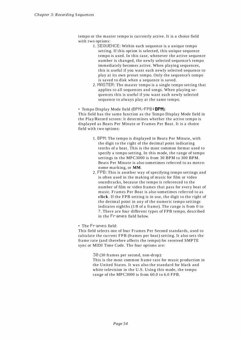
Chapter 3: Recording Sequences
Page 54
tempo or the master tempo is currently active. It is a choice fieldwith two options:
1. SEQUENCE: Within each sequence is a unique temposetting. If this option is selected, this unique sequencetempo is used. In this case, whenever the active sequencenumber is changed, the newly selected sequence’s tempoimmediately becomes active. When playing sequences,this is useful if you want each newly selected sequence toplay at its own preset tempo. Only the sequence’s tempois saved to disk when a sequence is saved.
2. MASTER: The master tempo is a single tempo setting thatapplies to all sequences and songs. When playing se-quences this is useful if you want each newly selectedsequence to always play at the same tempo.
• Tempo Display Mode field (BPM/FPB:BPMBPMBPMBPMBPM):This field has the same function as the Tempo Display Mode field inthe Play/Record screen: it determines whether the active tempo isdisplayed as Beats Per Minute or Frames Per Beat. It is a choicefield with two options:
1. BPM: The tempo is displayed in Beats Per Minute, withthe digit to the right of the decimal point indicatingtenths of a beat. This is the most common format used tospecify a tempo setting. In this mode, the range of temposettings in the MPC3000 is from 30 BPM to 300 BPM.Beats Per Minute is also sometimes referred to as metro-nome marking, or MM.
2. FPB: This is another way of specifying tempo settings andis often used in the making of music for film or videosoundtracks, because the tempo is referenced to thenumber of film or video frames that pass for every beat ofmusic. Frames Per Beat is also sometimes referred to asclick. If the FPB setting is in use, the digit to the right ofthe decimal point in any of the numeric tempo settingsindicates eighths (1/8 of a frame). The range is from 0 to7. There are four different types of FPB tempo, describedin the Frames field below.
• The Frames field:This field selects one of four Frames Per Second standards, used tocalculate the current FPB (frames per beat) setting. It also sets theframe rate (and therefore affects the tempo) for received SMPTEsync or MIDI Time Code. The four options are:
30 (30 frames per second, non-drop):This is the most common frame rate for music production inthe United States. It was also the standard for black andwhite television in the U.S. Using this mode, the temporange of the MPC3000 is from 60.0 to 6.0 FPB.
Chapter 3: Recording Sequences
Page 55
29.97 DROP (29.97 frames per second, drop frame):This is the standard for NTSC color television in the UnitedStates. Using this mode, the tempo range of the MPC3000 isfrom 59.7 to 6.0 FPB.
COMMENT: In the MPC60 version 2 software, thisselection was erroneously called 30DROP, although itwas actually 29.97 frames per second drop frametime code. Sorry.
25 (25 frames per second):This is the standard for European television (PAL /SECAMstandard). Using this mode, the tempo range of theMPC3000 is from 50.0 to 5.0 FPB.
24 (24 frames per second):This is the standard for film. However, since film is usuallytransferred to video for scoring, the composer still workswith the video standard frame rates. Using this mode, thetempo range of the MPC3000 is from 48.0 to 5.0 FPB.
• The Tap averaging fieldThis parameter is used in conjunction with the TAP TEMPO key.The TAP TEMPO key is used for quick setting of the playing tempoby repeatedly tapping 1/4-notes on the key at the desired tempo.(This is described further in the section “The Tap Tempo key.”)Repeated taps are averaged to help reduce timing errors; this fieldsets the number of taps that must be played successively before thetempo is recalculated. The options are:
2 taps:The tempo is recalculated after only two taps. This shouldbe used only if your timing is very good, or if you want to setthe new tempo roughly.
3 taps:Initially, the tempo is recalculated after the first two taps. Ifyou continue to tap successive 1/4-notes, the tempo iscontinuously recalculated by averaging the last threesuccessive tap intervals. This is a good average setting.
4 taps:Initially, the tempo is recalculated after the first two taps. Ifyou tap a third time, the tempo will be recalculated using anaverage of the three taps. If you continue to tap successive 1/4-notes, the tempo is continuously recalculated on eachsuccessive tap by averaging the last four successive tapintervals. This is very useful if your timing is not veryaccurate, because it smoothes out your timing errors.
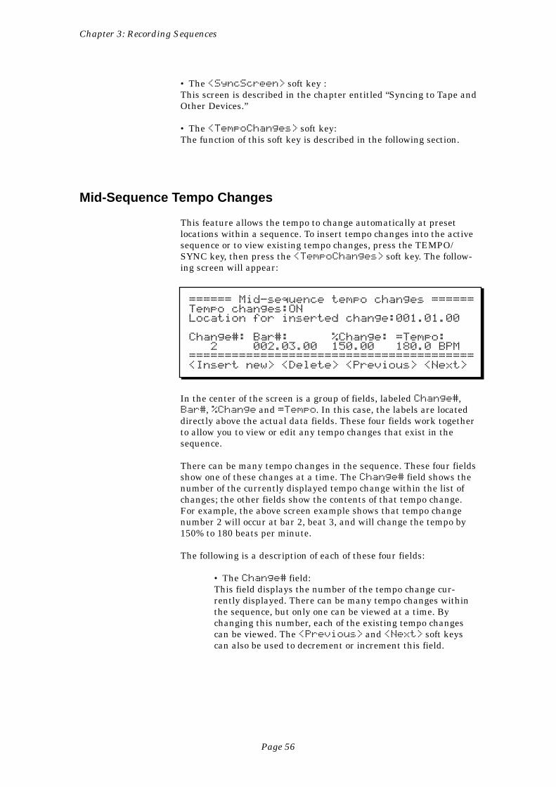
Chapter 3: Recording Sequences
Page 56
• The <SyncScreen> soft key :This screen is described in the chapter entitled “Syncing to Tape andOther Devices.”
• The <TempoChanges> soft key:The function of this soft key is described in the following section.
Mid-Sequence Tempo Changes
This feature allows the tempo to change automatically at presetlocations within a sequence. To insert tempo changes into the activesequence or to view existing tempo changes, press the TEMPO/SYNC key, then press the <TempoChanges> soft key. The follow-ing screen will appear:
====== Mid-sequence tempo changes ======Tempo changes:ONLocation for inserted change:001.01.00
Change#: Bar#: %Change: =Tempo: 2 002.03.00 150.00 180.0 BPM========================================<Insert new> <Delete> <Previous> <Next>
In the center of the screen is a group of fields, labeled Change#,Bar#, %Change and =Tempo. In this case, the labels are locateddirectly above the actual data fields. These four fields work togetherto allow you to view or edit any tempo changes that exist in thesequence.
There can be many tempo changes in the sequence. These four fieldsshow one of these changes at a time. The Change# field shows thenumber of the currently displayed tempo change within the list ofchanges; the other fields show the contents of that tempo change.For example, the above screen example shows that tempo changenumber 2 will occur at bar 2, beat 3, and will change the tempo by150% to 180 beats per minute.
The following is a description of each of these four fields:
• The Change# field:This field displays the number of the tempo change cur-rently displayed. There can be many tempo changes withinthe sequence, but only one can be viewed at a time. Bychanging this number, each of the existing tempo changescan be viewed. The <Previous> and <Next> soft keyscan also be used to decrement or increment this field.
Chapter 3: Recording Sequences
Page 57
• The Bar# field:This field shows the location within the sequence where thecurrently displayed tempo change will occur. This is abar.beat.tick field.
• The %Change field:This field shows, as a percentage of the main starting tempo(either MASTER or SEQUENCE), the amount of tempochange that the currently displayed tempo will produce.Tempo changes are always specified as a percentage of themain starting tempo setting (not the previous tempochange), regardless of whether the SEQUENCE or MASTERtempo setting is currently active. This way, all tempochanges are automatically re-scaled when the main temposetting (either SEQUENCE or MASTER) is changed.
• The =Tempo field:This field displays the actual tempo number that will playonce the tempo change is active. This number is automati-cally computed from the displayed percentage of changemultiplied by the main playing tempo (either MASTER orSEQUENCE).
To view the entire list of tempo changes, simply modify theChange# field and notice the different settings of the other threefields as you change it. Even if no changes have been entered, everysequence has one change—to 100% at bar 1. This is because thecurrent tempo setting is always returned to when the sequenceplays bar 1, whether it does so by playing from the start or bylooping back to the start.
To insert a new tempo change, enter the location within the se-quence where you want the change to occur into the Locationfor inserted change field, which is a bar.beat.tick field.Then press the <Insert new> soft key. Immediately, a newtempo change will be inserted into the list, displayed on the screenwith a default value in the %Change field of 100%. You must nowenter a percentage of the main starting tempo. As you enter thepercentage, the =Tempo field will show the actual tempo. Forexample, to insert a tempo change to 60 BPM at bar 5 from a mainstarting tempo of 120 BPM, you must insert a tempo change with avalue of 50% at bar 5 (120 BPM X 50% = 60 BPM).
To delete the currently displayed tempo change, press the<Delete> soft key.
The field at the top of the screen, Tempo changes, is a choicefield with two options: ON and OFF. If set to ON, tempo changes areused; if set to OFF, all tempo changes within the sequence areignored.
Chapter 3: Recording Sequences
Page 58
The TAP TEMPO Key
The TAP TEMPO key allows the tempo to be set quickly by tappingtwo beats (1/4-notes) on the TAP TEMPO key. After two taps, theMPC3000 automatically assumes the two taps to be 1/4-notes andrecalculates a new tempo to match those 1/4-notes.
For example, to quickly change to a tempo of 80 BPM, tap two 1/4-notes at a tempo of approximately 80 BPM on the TAP TEMPO key.After the second tap, the new tempo will appear in the Active Tempofield of the Play/Record screen. This can also be done while thesequence is playing.
Normally, only two taps are required before the MPC3000 recalcu-lates the new tempo. However, it is possible to set this feature sothat it recalculates the tempo by averaging the last three (or four)successive tap intervals. This is set in the Tap averaging field,located in the Tempo screen. More information about using the TAPTEMPO key is contained in the “Tempo and the TEMPO/SYNC Key”section of the manual, earlier in this chapter.
Chapter 3: Recording Sequences
Page 59
The WAIT FOR and COUNT IN Keys
These two keys make the process of real-time sequence recordingeasier.
The WAIT FOR KEY key
This function is useful in the recording of keyboard sequences whenyour keyboard is not located close to the MPC3000. If Play, Recordor Overdub mode is entered while the Wait For Key function is on,the sequence will not begin to play until a key is played on the MIDIkeyboard. This acts as a remote switch to start the sequence play-ing. Note that the first key that is played to start the sequence isNOT recorded into the sequence—it only starts the sequence. Allkeys played after recording has been initiated are recorded into thesequence.
To turn Wait For Key mode on, press the WAIT FOR KEY key once;the light goes on to indicate it has been activated. To turn the modeoff, press the WAIT FOR KEY key again and the light will go off. Ifset to ON, it will automatically go OFF after it has been used once(for playback, recording, or overdubbing a sequence). You must turnit on again each time you want to use it.
The COUNT IN key
If the Count In function is on, one bar of metronome clicks willprecede the playing of the sequence or song whenever you initiateplayback of a sequence or song. The clicks provide a tempo guide toprepare you to record or play along with the sequence.
Press COUNT IN to turn the function on and again to turn it off.While on, the light above the key is lit.
It is possible to select a mode in which the count in only occursbefore recording and not before playing. To select this mode and toadjust other metronome parameters, press the OTHER key. Thesefeatures are explained in the “OTHER Key” section, later in thischapter.
COMMENT: While the Count In bar is playing, keys playedon the MIDI keyboard will not be output through MIDI (viathe MPC3000 ‘s Soft Thru function) until the Count In barhas finished. For example, if you were to play a chord duringthe count in bar, the chord would not sound until bar 1started playing. This is normal operation and serves as areminder that no notes can be recorded during the count inbar, and that any notes played during that time will be heldand recorded at the start of the sequence.
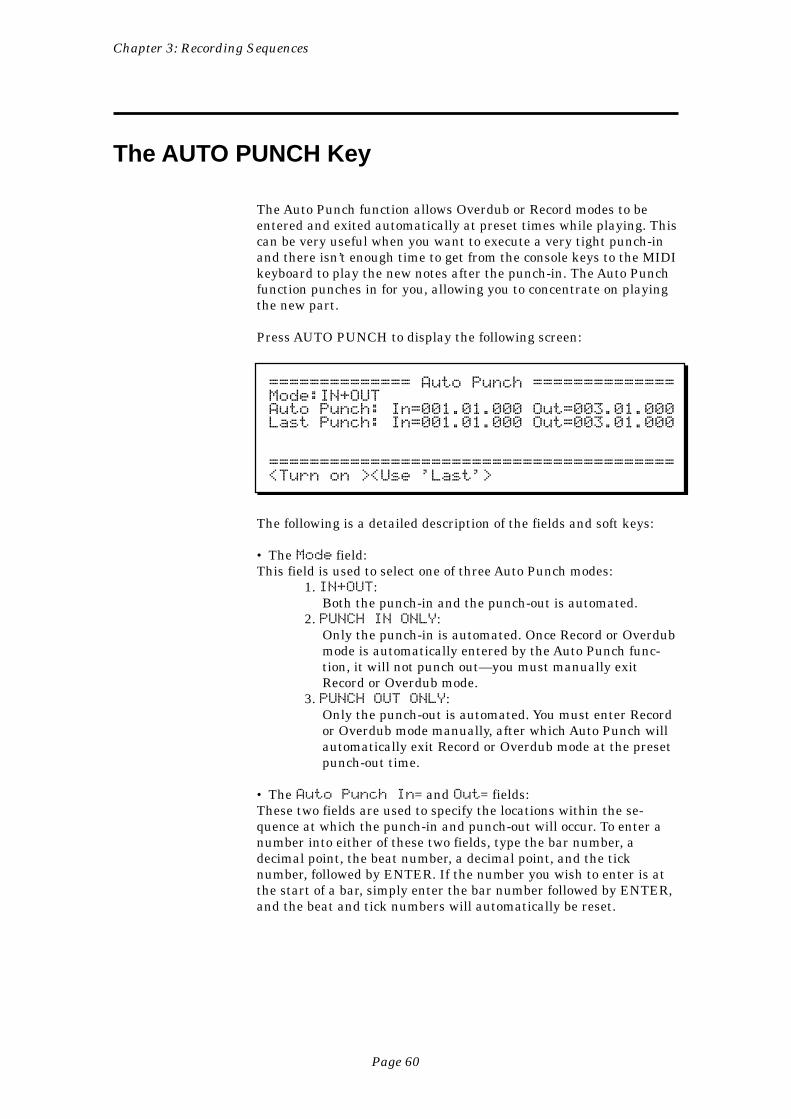
Chapter 3: Recording Sequences
Page 60
The AUTO PUNCH Key
The Auto Punch function allows Overdub or Record modes to beentered and exited automatically at preset times while playing. Thiscan be very useful when you want to execute a very tight punch-inand there isn’t enough time to get from the console keys to the MIDIkeyboard to play the new notes after the punch-in. The Auto Punchfunction punches in for you, allowing you to concentrate on playingthe new part.
Press AUTO PUNCH to display the following screen:
============== Auto Punch ==============Mode:IN+OUTAuto Punch: In=001.01.000 Out=003.01.000Last Punch: In=001.01.000 Out=003.01.000
========================================<Turn on ><Use 'Last'>
The following is a detailed description of the fields and soft keys:
• The Mode field:This field is used to select one of three Auto Punch modes:
1. IN+OUT:Both the punch-in and the punch-out is automated.
2. PUNCH IN ONLY:Only the punch-in is automated. Once Record or Overdubmode is automatically entered by the Auto Punch func-tion, it will not punch out—you must manually exitRecord or Overdub mode.
3. PUNCH OUT ONLY:Only the punch-out is automated. You must enter Recordor Overdub mode manually, after which Auto Punch willautomatically exit Record or Overdub mode at the presetpunch-out time.
• The Auto Punch In= and Out= fields:These two fields are used to specify the locations within the se-quence at which the punch-in and punch-out will occur. To enter anumber into either of these two fields, type the bar number, adecimal point, the beat number, a decimal point, and the ticknumber, followed by ENTER. If the number you wish to enter is atthe start of a bar, simply enter the bar number followed by ENTER,and the beat and tick numbers will automatically be reset.
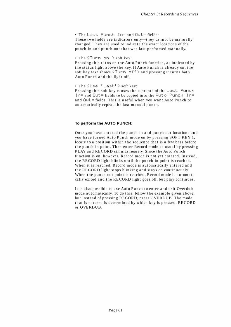
Chapter 3: Recording Sequences
Page 61
• The Last Punch In= and Out= fields:These two fields are indicators only—they cannot be manuallychanged. They are used to indicate the exact locations of thepunch-in and punch-out that was last performed manually.
• The <Turn on > soft key:Pressing this turns on the Auto Punch function, as indicated bythe status light above the key. If Auto Punch is already on, thesoft key text shows <Turn off> and pressing it turns bothAuto Punch and the light off.
• The <Use 'Last'> soft key:Pressing this soft key causes the contents of the Last PunchIn= and Out= fields to be copied into the Auto Punch In=and Out= fields. This is useful when you want Auto Punch toautomatically repeat the last manual punch.
To perform the AUTO PUNCH:
Once you have entered the punch-in and punch-out locations andyou have turned Auto Punch mode on by pressing SOFT KEY 1,locate to a position within the sequence that is a few bars beforethe punch-in point. Then enter Record mode as usual by pressingPLAY and RECORD simultaneously. Since the Auto Punchfunction is on, however, Record mode is not yet entered. Instead,the RECORD light blinks until the punch-in point is reached.When it is reached, Record mode is automatically entered andthe RECORD light stops blinking and stays on continuously.When the punch-out point is reached, Record mode is automati-cally exited and the RECORD light goes off, but play continues.
It is also possible to use Auto Punch to enter and exit Overdubmode automatically. To do this, follow the example given above,but instead of pressing RECORD, press OVERDUB. The modethat is entered is determined by which key is pressed, RECORDor OVERDUB.
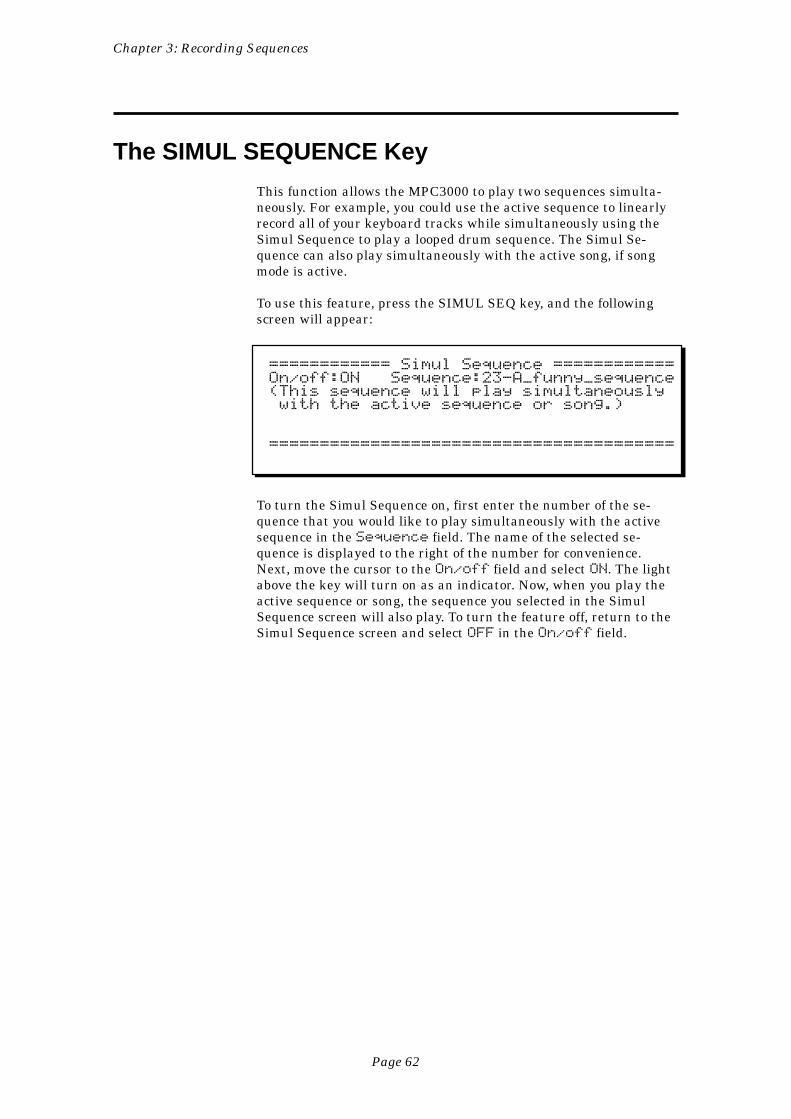
Chapter 3: Recording Sequences
Page 62
The SIMUL SEQUENCE Key
This function allows the MPC3000 to play two sequences simulta-neously. For example, you could use the active sequence to linearlyrecord all of your keyboard tracks while simultaneously using theSimul Sequence to play a looped drum sequence. The Simul Se-quence can also play simultaneously with the active song, if songmode is active.
To use this feature, press the SIMUL SEQ key, and the followingscreen will appear:
============ Simul Sequence ============On/off:ON Sequence:23-A_funny_sequence(This sequence will play simultaneously with the active sequence or song.)
========================================
To turn the Simul Sequence on, first enter the number of the se-quence that you would like to play simultaneously with the activesequence in the Sequence field. The name of the selected se-quence is displayed to the right of the number for convenience.Next, move the cursor to the On/off field and select ON. The lightabove the key will turn on as an indicator. Now, when you play theactive sequence or song, the sequence you selected in the SimulSequence screen will also play. To turn the feature off, return to theSimul Sequence screen and select OFF in the On/off field.
Chapter 3: Recording Sequences
Page 63
The OTHER Key
The OTHER key gives you access to a number of additional features,many of which are related to sequence recording:
• Metronome controls: Provides adjustments for the recordingmetronome and Count In function.• Foot Switches: Allows the two foot switch inputs to be assigned.• Free sequence memory display: Shows the current percentage ofsequence memory available for recording.• Initialize system parameters: Provides access to the Initialize PARFile Data screen, which allows the initialization of all generalparameters in the MPC3000. This function is further described inthe “Initializing System Parameters” section later in this chapter.• Record 16 channels simultaneously: Provides access to the Record16 Channels function, which allows all 16 incoming MIDI channelsto be recorded simultaneously, useful when transferring sequencesfrom another sequencer to the MPC300. This function is detailed inthe “Record 16 Channels Function: Multichannel Recording” sectionlater in this chapter.
Metronome, Foot Switches, and Free Sequence Memory
When the OTHER key is pressed, the following screen appears:
============== Metronome ===============Volume:100 In play:YES Output:STEREOCount IN:REC ONLY Rate:1/4 NOTE====== Foot Switches / Free Memory =====Foot1:PLAY-STRT/STP Foot2:RECORD IN/OUTFree seq mem:100%========================================<Init PAR><Rec 16 Chs>
The fields and soft keys are:
The Metronome section:
• The Volume field:This field controls the volume of the metronome, from 0 to 100.
• The In play field:This is a choice field that has two options:
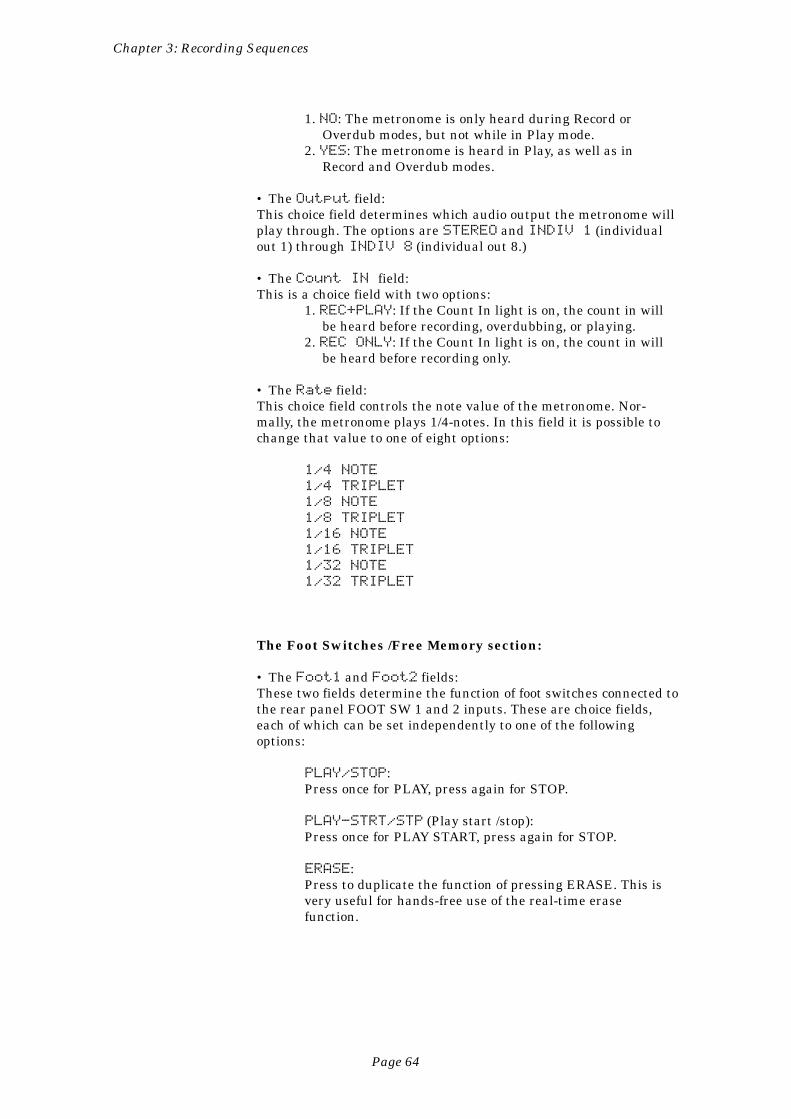
Chapter 3: Recording Sequences
Page 64
1. NO: The metronome is only heard during Record orOverdub modes, but not while in Play mode.
2. YES: The metronome is heard in Play, as well as inRecord and Overdub modes.
• The Output field:This choice field determines which audio output the metronome willplay through. The options are STEREO and INDIV 1 (individualout 1) through INDIV 8 (individual out 8.)
• The Count IN field:This is a choice field with two options:
1. REC+PLAY: If the Count In light is on, the count in willbe heard before recording, overdubbing, or playing.
2. REC ONLY: If the Count In light is on, the count in willbe heard before recording only.
• The Rate field:This choice field controls the note value of the metronome. Nor-mally, the metronome plays 1/4-notes. In this field it is possible tochange that value to one of eight options:
1/4 NOTE
1/4 TRIPLET
1/8 NOTE
1/8 TRIPLET
1/16 NOTE
1/16 TRIPLET
1/32 NOTE
1/32 TRIPLET
The Foot Switches /Free Memory section:
• The Foot1 and Foot2 fields:These two fields determine the function of foot switches connected tothe rear panel FOOT SW 1 and 2 inputs. These are choice fields,each of which can be set independently to one of the followingoptions:
PLAY/STOP:Press once for PLAY, press again for STOP.
PLAY-STRT/STP (Play start /stop):Press once for PLAY START, press again for STOP.
ERASE:Press to duplicate the function of pressing ERASE. This isvery useful for hands-free use of the real-time erasefunction.
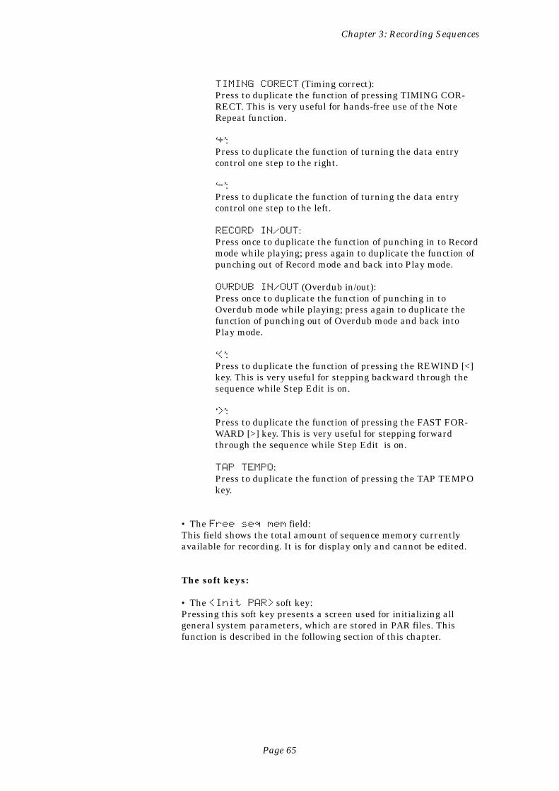
Chapter 3: Recording Sequences
Page 65
TIMING CORECT (Timing correct):Press to duplicate the function of pressing TIMING COR-RECT. This is very useful for hands-free use of the NoteRepeat function.
‘+’:Press to duplicate the function of turning the data entrycontrol one step to the right.
‘-’:Press to duplicate the function of turning the data entrycontrol one step to the left.
RECORD IN/OUT:Press once to duplicate the function of punching in to Recordmode while playing; press again to duplicate the function ofpunching out of Record mode and back into Play mode.
OVRDUB IN/OUT (Overdub in/out):Press once to duplicate the function of punching in toOverdub mode while playing; press again to duplicate thefunction of punching out of Overdub mode and back intoPlay mode.
‘<’:Press to duplicate the function of pressing the REWIND [<]key. This is very useful for stepping backward through thesequence while Step Edit is on.
‘>’:Press to duplicate the function of pressing the FAST FOR-WARD [>] key. This is very useful for stepping forwardthrough the sequence while Step Edit is on.
TAP TEMPO:Press to duplicate the function of pressing the TAP TEMPOkey.
• The Free seq mem field:This field shows the total amount of sequence memory currentlyavailable for recording. It is for display only and cannot be edited.
The soft keys:
• The <Init PAR> soft key:Pressing this soft key presents a screen used for initializing allgeneral system parameters, which are stored in PAR files. Thisfunction is described in the following section of this chapter.
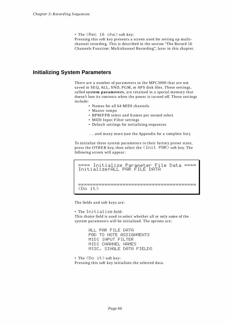
Chapter 3: Recording Sequences
Page 66
• The <Rec 16 chs> soft key:Pressing this soft key presents a screen used for setting up multi-channel recording. This is described in the section “The Record 16Channels Function: Multichannel Recording”, later in this chapter.
Initializing System Parameters
There are a number of parameters in the MPC3000 that are notsaved in SEQ, ALL, SND, PGM, or APS disk files. These settings,called system parameters, are retained in a special memory thatdoesn’t lose its contents when the power is turned off. These settingsinclude:
• Names for all 64 MIDI channels• Master tempo• BPM/FPB select and frames per second select• MIDI Input Filter settings• Default settings for initializing sequences
. . .and many more (see the Appendix for a complete list).
To initialize these system parameters to their factory preset state,press the OTHER key, then select the <Init PAR> soft key. Thefollowing screen will appear:
==== Initialize Parameter File Data ====Initialize:ALL PAR FILE DATA
========================================<Do it>
The fields and soft keys are:
• The Initialize field:This choice field is used to select whether all or only some of thesystem parameters will be initialized. The options are:
ALL PAR FILE DATA
PAD TO NOTE ASSIGNMENTS
MIDI INPUT FILTER
MIDI CHANNEL NAMES
MISC. SINGLE DATA FIELDS
• The <Do it> soft key:Pressing this soft key initializes the selected data.
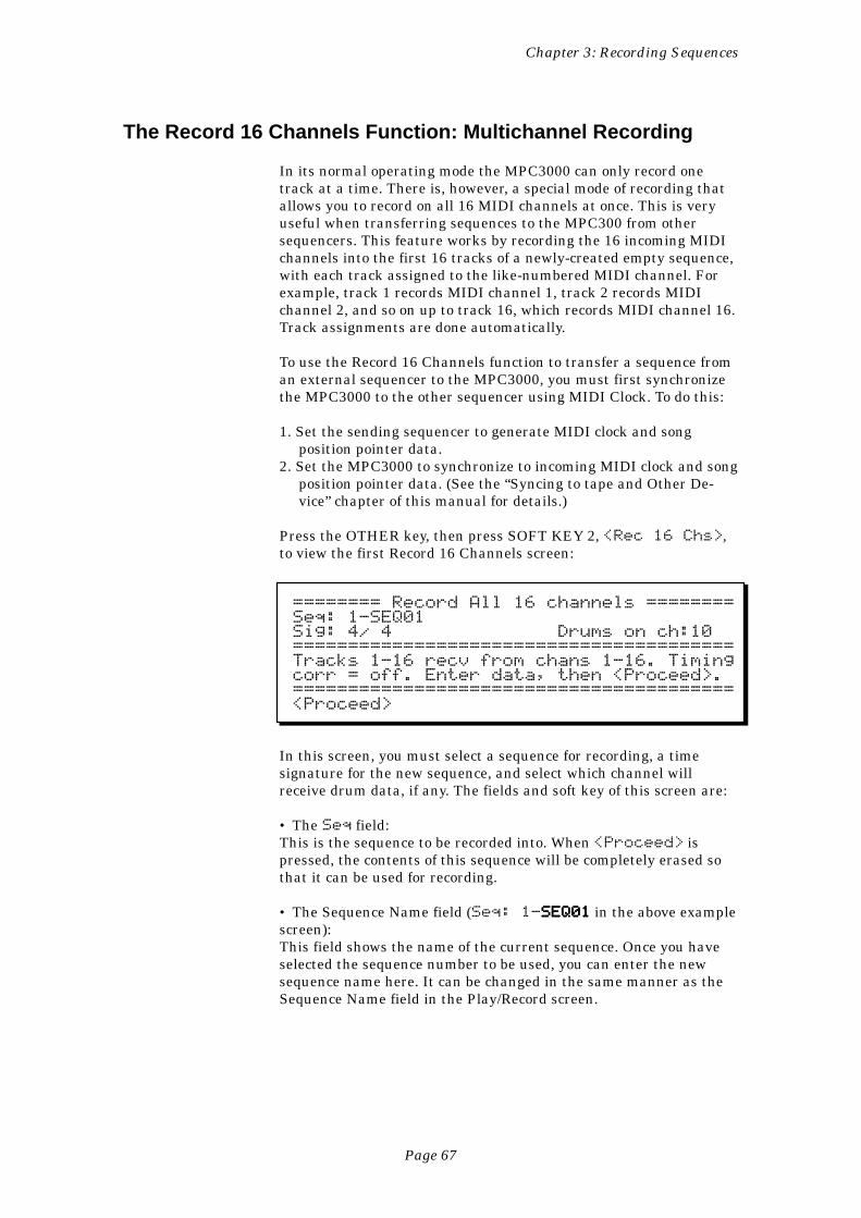
Chapter 3: Recording Sequences
Page 67
The Record 16 Channels Function: Multichannel Recording
In its normal operating mode the MPC3000 can only record onetrack at a time. There is, however, a special mode of recording thatallows you to record on all 16 MIDI channels at once. This is veryuseful when transferring sequences to the MPC300 from othersequencers. This feature works by recording the 16 incoming MIDIchannels into the first 16 tracks of a newly-created empty sequence,with each track assigned to the like-numbered MIDI channel. Forexample, track 1 records MIDI channel 1, track 2 records MIDIchannel 2, and so on up to track 16, which records MIDI channel 16.Track assignments are done automatically.
To use the Record 16 Channels function to transfer a sequence froman external sequencer to the MPC3000, you must first synchronizethe MPC3000 to the other sequencer using MIDI Clock. To do this:
1. Set the sending sequencer to generate MIDI clock and songposition pointer data.
2. Set the MPC3000 to synchronize to incoming MIDI clock and songposition pointer data. (See the “Syncing to tape and Other De-vice” chapter of this manual for details.)
Press the OTHER key, then press SOFT KEY 2, <Rec 16 Chs>,to view the first Record 16 Channels screen:
======== Record All 16 channels ========Seq: 1-SEQ01Sig: 4/ 4 Drums on ch:10========================================Tracks 1-16 recv from chans 1-16. Timingcorr = off. Enter data, then <Proceed>.========================================<Proceed>
In this screen, you must select a sequence for recording, a timesignature for the new sequence, and select which channel willreceive drum data, if any. The fields and soft key of this screen are:
• The Seq field:This is the sequence to be recorded into. When <Proceed> ispressed, the contents of this sequence will be completely erased sothat it can be used for recording.
• The Sequence Name field (Seq: 1-SEQ01SEQ01SEQ01SEQ01SEQ01 in the above examplescreen):This field shows the name of the current sequence. Once you haveselected the sequence number to be used, you can enter the newsequence name here. It can be changed in the same manner as theSequence Name field in the Play/Record screen.
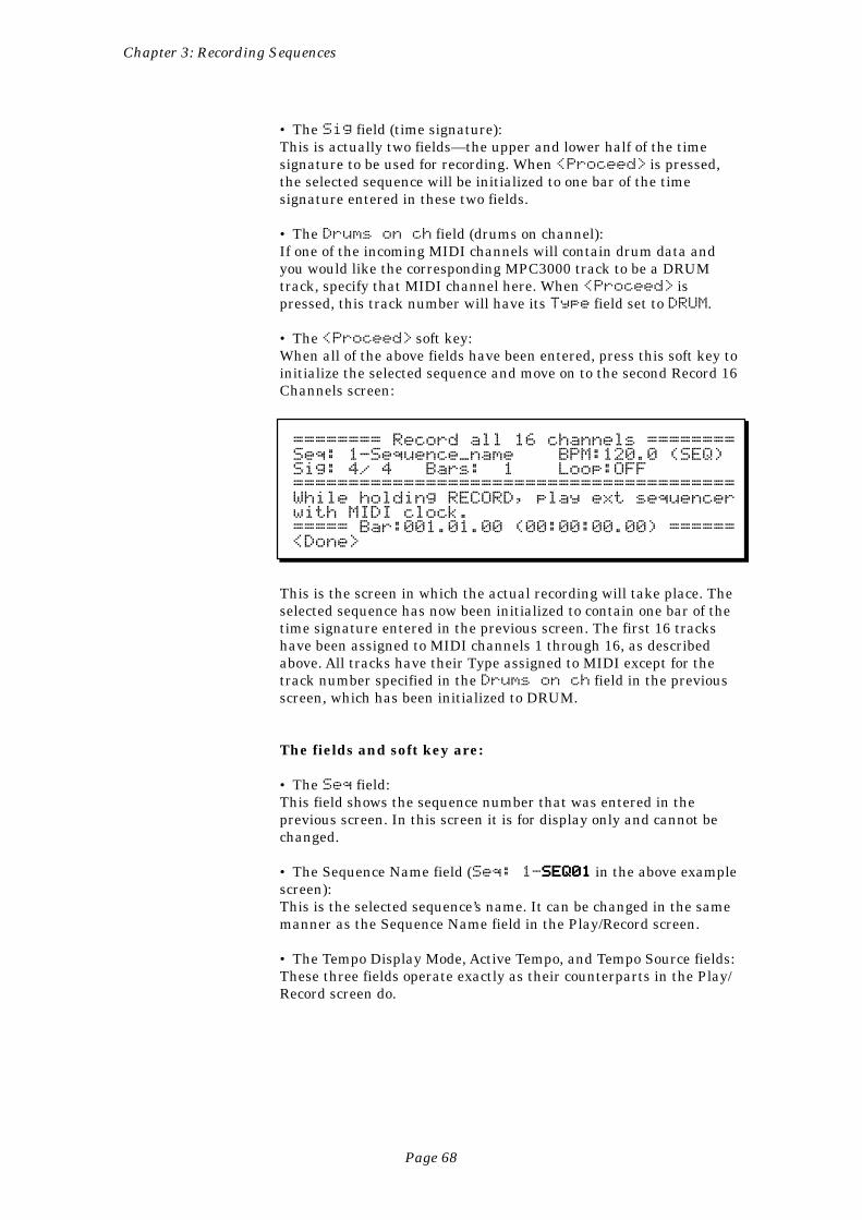
Chapter 3: Recording Sequences
Page 68
• The Sig field (time signature):This is actually two fields—the upper and lower half of the timesignature to be used for recording. When <Proceed> is pressed,the selected sequence will be initialized to one bar of the timesignature entered in these two fields.
• The Drums on ch field (drums on channel):If one of the incoming MIDI channels will contain drum data andyou would like the corresponding MPC3000 track to be a DRUMtrack, specify that MIDI channel here. When <Proceed> ispressed, this track number will have its Type field set to DRUM.
• The <Proceed> soft key:When all of the above fields have been entered, press this soft key toinitialize the selected sequence and move on to the second Record 16Channels screen:
======== Record all 16 channels ========Seq: 1-Sequence_name BPM:120.0 (SEQ)Sig: 4/ 4 Bars: 1 Loop:OFF========================================While holding RECORD, play ext sequencerwith MIDI clock.===== Bar:001.01.00 (00:00:00.00) ======<Done>
This is the screen in which the actual recording will take place. Theselected sequence has now been initialized to contain one bar of thetime signature entered in the previous screen. The first 16 trackshave been assigned to MIDI channels 1 through 16, as describedabove. All tracks have their Type assigned to MIDI except for thetrack number specified in the Drums on ch field in the previousscreen, which has been initialized to DRUM.
The fields and soft key are:
• The Seq field:This field shows the sequence number that was entered in theprevious screen. In this screen it is for display only and cannot bechanged.
• The Sequence Name field (Seq: 1-SEQ01SEQ01SEQ01SEQ01SEQ01 in the above examplescreen):This is the selected sequence’s name. It can be changed in the samemanner as the Sequence Name field in the Play/Record screen.
• The Tempo Display Mode, Active Tempo, and Tempo Source fields:These three fields operate exactly as their counterparts in the Play/Record screen do.
Chapter 3: Recording Sequences
Page 69
• The Sig field (time signature):This field shows the time signature entered in the previous screen.It is for display only and cannot be changed.
• The Bars fieldThis shows the total number of bars in the newly initialized se-quence, which is always initialized to 1 bar. When recording begins,additional bars will be added to the end of the sequence as needed,as is normal when the Loop field is set to OFF in the Play/Recordscreen.
• The Loop field:This is for display only and cannot be changed. It indicates that thesequence’s Loop field is forced to OFF because loop recording is notpermitted during 16 channel recording.
• The <Done> soft key:When finished recording, press this soft key to exit to the Play/Record screen with your new sequence intact.
To record the incoming sequence:
While holding the RECORD key on the MPC3000, start the exter-nal sequencer playing from the beginning of its sequence. As soon asthe MPC3000 receives the sync signals, it will enter Record modeand begin recording the data from the other sequencer in real time.(Note: The OVERDUB key is disabled during 16 channel recording.)Once the transfer is finished, stop the external sequencer (theMPC3000 will stop automatically) or manually stop the MPC3000.
The MPC3000 now contains the transferred sequence, which can beplayed using the PLAY, PLAY START, REWIND, FAST FORWARDand LOCATE keys. Play the sequence; if the transfer was success-ful, press <Done> to return to the Play/Record screen. If thetransfer didn’t come out as intended, try again by holding RECORDand starting the other sequencer.
COMMENT: If the incoming multitrack sequence contains alarge amount of data or is playing at a very fast tempo, it ispossible for the MPC3000 to become overloaded, causingdelays in the timing of the recorded sequence. If this occurs,reduce the tempo of the sending sequencer. This will lower theMPC3000’s processing requirement, and should eliminateany overload errors.
Chapter 3: Recording Sequences
Page 70
Recording MIDI System-Exclusive Data
The MPC3000 can record patch data or any other MIDI system-exclusive messages from external synthesizers directly into tracks.To do this, simply send the system-exclusive message to theMPC3000 while in Record, Overdub, or Step Edit mode, and it willbe recorded into the active track, just the same as any other MIDIdata. The only limitation is that the message must be smaller than1000 bytes. If an attempt is made to record a message that is largerthan that, the entire message will be rejected. 1000 bytes is enoughto accommodate a single voice patch data dump from virtually anysynthesizer, but it is not large enough for many voice bank datadumps (large files containing an entire bank of synthesizer patches).
One way of using this feature is to insert a blank bar at the begin-ning of your sequence and record the voice data dumps for eachtrack into that first bar. When the sequence is played from the start,each external synthesizer will immediately receive the voice data inthe first bar, so it will be ready to play the note data starting in thesecond bar with the proper sound.
There is one problem with playing system-exclusive messages fromsequences: there is no standard method for identifying the MIDIchannel number within the message, and therefore the MPC3000cannot assign the output MIDI channel over which the message willbe sent. This means, for example, that a system-exclusive messagereceived over MIDI channel 3 while recording into the MPC3000will always be played out of the MPC3000 on MIDI channel 3,regardless of the track’s output MIDI channel. To overcome thisproblem, you must send the system-exclusive message on thedesired MIDI channel while recording it into the MPC3000. Mostsynthesizers allow you to select the transmit channel. Note, how-ever, that some older synthesizers, such as the original Yamaha DX-7, always transmit on MIDI channel 1.
However, there is a way to change the MIDI channel of a system-exclusive message while it is in the MPC3000—by using Step Edit.The MIDI channel is assigned to a single byte within the messageand the Step Edit function allows you to change the contents of anybyte within the message. If you know which byte a particularmanufacturer uses for the channel number, you can change thecontents of that byte to the desired MIDI channel number. Forexample, the Yamaha DX-7 system-exclusive messages contain theMIDI channel in byte number 3, so whatever number you put intobyte number 3 of the message will be the new output MIDI channelnumber. To learn more about editing in Step Edit mode, read “TheSTEP EDIT Key” section in the “Editing Sequences” chapter of thismanual.
Page 71
Chapter 4: Editing Sequence
Chapter 4:Editing Sequences
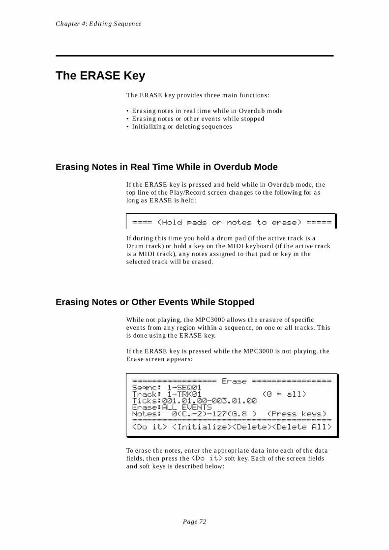
Page 72
Chapter 4: Editing Sequence
The ERASE Key
The ERASE key provides three main functions:
• Erasing notes in real time while in Overdub mode• Erasing notes or other events while stopped• Initializing or deleting sequences
Erasing Notes in Real Time While in Overdub Mode
If the ERASE key is pressed and held while in Overdub mode, thetop line of the Play/Record screen changes to the following for aslong as ERASE is held:
==== (Hold pads or notes to erase) =====
If during this time you hold a drum pad (if the active track is aDrum track) or hold a key on the MIDI keyboard (if the active trackis a MIDI track), any notes assigned to that pad or key in theselected track will be erased.
Erasing Notes or Other Events While Stopped
While not playing, the MPC3000 allows the erasure of specificevents from any region within a sequence, on one or all tracks. Thisis done using the ERASE key.
If the ERASE key is pressed while the MPC3000 is not playing, theErase screen appears:
================= Erase ================Seqnc: 1-SEQ01Track: 1-TRK01 (0 = all)Ticks:001.01.00-003.01.00Erase:ALL EVENTSNotes: 0(C.-2)-127(G.8 ) (Press keys)========================================<Do it> <Initialize><Delete><Delete All>
To erase the notes, enter the appropriate data into each of the datafields, then press the <Do it> soft key. Each of the screen fieldsand soft keys is described below:
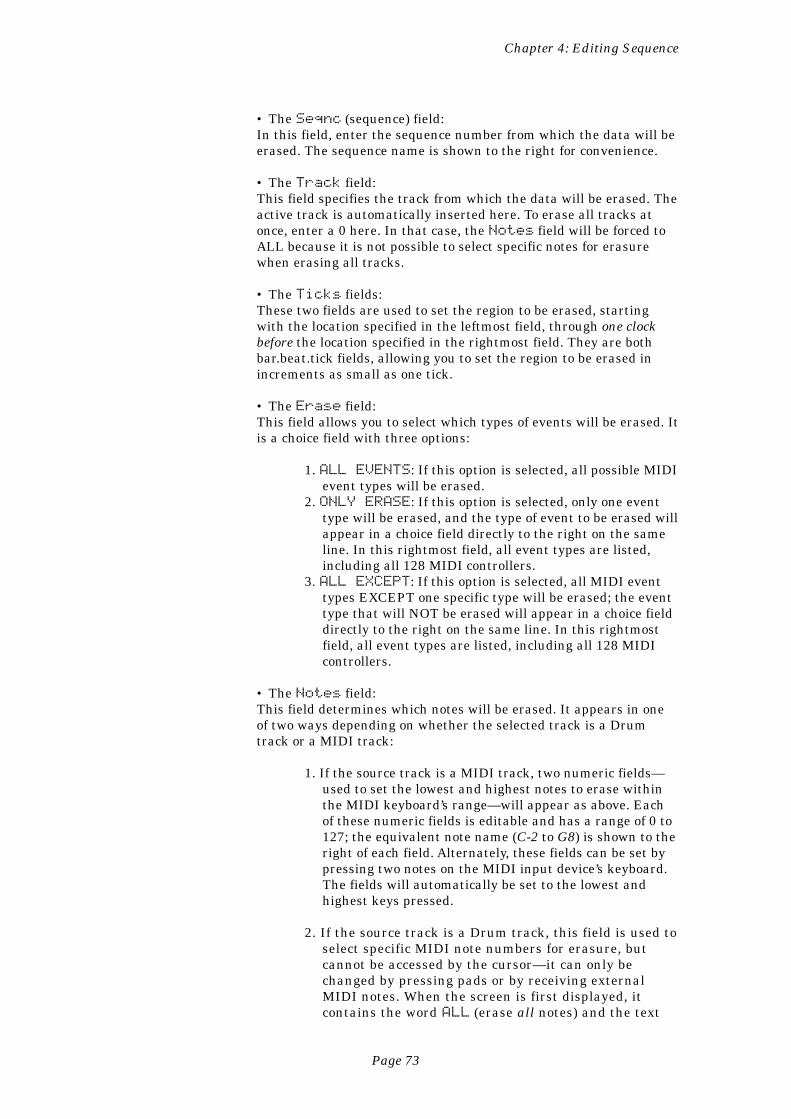
Page 73
Chapter 4: Editing Sequence
• The Seqnc (sequence) field:In this field, enter the sequence number from which the data will beerased. The sequence name is shown to the right for convenience.
• The Track field:This field specifies the track from which the data will be erased. Theactive track is automatically inserted here. To erase all tracks atonce, enter a 0 here. In that case, the Notes field will be forced toALL because it is not possible to select specific notes for erasurewhen erasing all tracks.
• The Ticks fields:These two fields are used to set the region to be erased, startingwith the location specified in the leftmost field, through one clockbefore the location specified in the rightmost field. They are bothbar.beat.tick fields, allowing you to set the region to be erased inincrements as small as one tick.
• The Erase field:This field allows you to select which types of events will be erased. Itis a choice field with three options:
1. ALL EVENTS: If this option is selected, all possible MIDIevent types will be erased.
2. ONLY ERASE: If this option is selected, only one eventtype will be erased, and the type of event to be erased willappear in a choice field directly to the right on the sameline. In this rightmost field, all event types are listed,including all 128 MIDI controllers.
3. ALL EXCEPT: If this option is selected, all MIDI eventtypes EXCEPT one specific type will be erased; the eventtype that will NOT be erased will appear in a choice fielddirectly to the right on the same line. In this rightmostfield, all event types are listed, including all 128 MIDIcontrollers.
• The Notes field:This field determines which notes will be erased. It appears in oneof two ways depending on whether the selected track is a Drumtrack or a MIDI track:
1. If the source track is a MIDI track, two numeric fields—used to set the lowest and highest notes to erase withinthe MIDI keyboard’s range—will appear as above. Eachof these numeric fields is editable and has a range of 0 to127; the equivalent note name (C-2 to G8) is shown to theright of each field. Alternately, these fields can be set bypressing two notes on the MIDI input device’s keyboard.The fields will automatically be set to the lowest andhighest keys pressed.
2. If the source track is a Drum track, this field is used toselect specific MIDI note numbers for erasure, butcannot be accessed by the cursor—it can only bechanged by pressing pads or by receiving externalMIDI notes. When the screen is first displayed, itcontains the word ALL (erase all notes) and the text
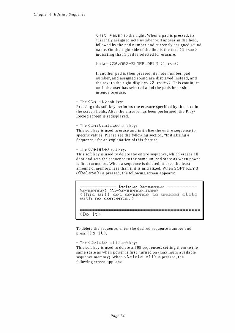
Page 74
Chapter 4: Editing Sequence
(Hit pads) to the right. When a pad is pressed, itscurrently assigned note number will appear in the field,followed by the pad number and currently assigned soundname. On the right side of the line is the text (1 pad)
indicating that 1 pad is selected for erasure:
Notes:36/A02-SNARE_DRUM (1 pad)
If another pad is then pressed, its note number, padnumber, and assigned sound are displayed instead, andthe text to the right displays (2 pads). This continuesuntil the user has selected all of the pads he or sheintends to erase.
• The <Do it> soft key:Pressing this soft key performs the erasure specified by the data inthe screen fields. After the erasure has been performed, the Play/Record screen is redisplayed.
• The <Initialize> soft key:This soft key is used to erase and initialize the entire sequence tospecific values. Please see the following section, “Initializing aSequence,” for an explanation of this feature.
• The <Delete> soft key:This soft key is used to delete the entire sequence, which erases alldata and sets the sequence to the same unused state as when poweris first turned on. When a sequence is deleted, it uses the leastamount of memory, less than if it is initialized. When SOFT KEY 3(<Delete>) is pressed, the following screen appears:
============ Delete Sequence ==========Sequence: 23-Sequence_name(This will set sequence to unused statewith no contents.)
========================================<Do it>
To delete the sequence, enter the desired sequence number andpress <Do it>.
• The <Delete all> soft key:This soft key is used to delete all 99 sequences, setting them to thesame state as when power is first turned on (maximum availablesequence memory). When <Delete all> is pressed, thefollowing screen appears:
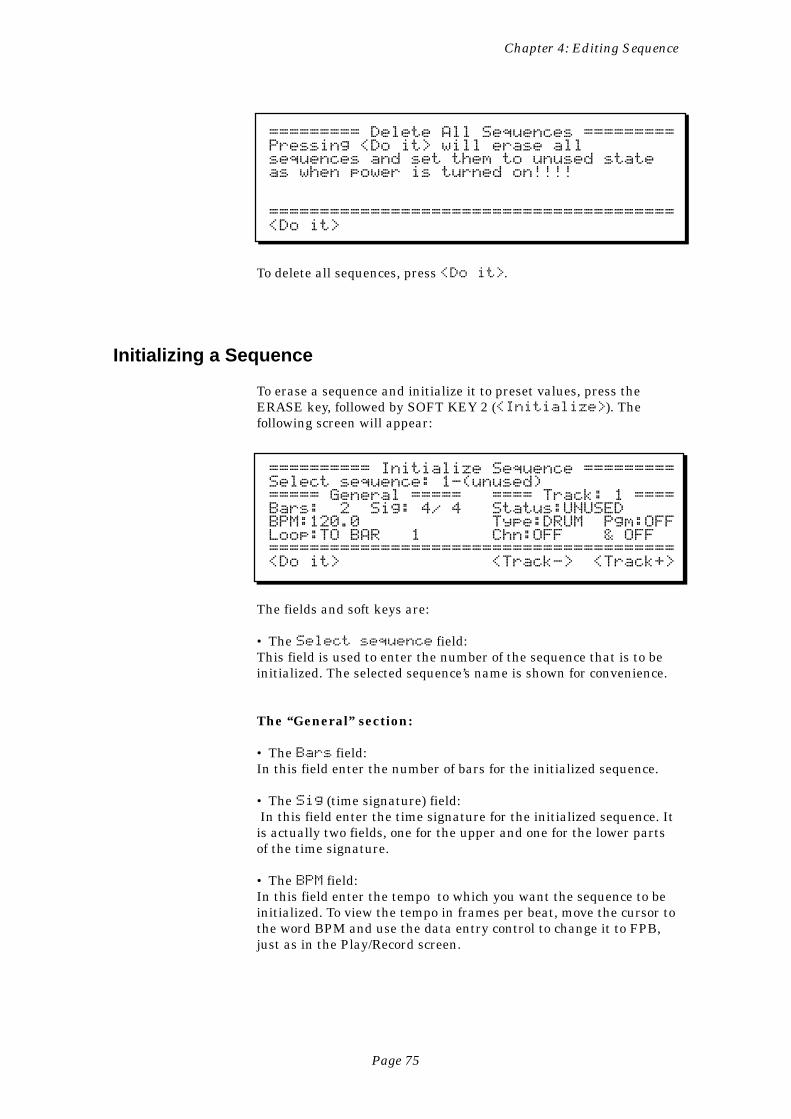
Page 75
Chapter 4: Editing Sequence
========= Delete All Sequences =========Pressing <Do it> will erase allsequences and set them to unused stateas when power is turned on!!!!
========================================<Do it>
To delete all sequences, press <Do it>.
Initializing a Sequence
To erase a sequence and initialize it to preset values, press theERASE key, followed by SOFT KEY 2 (<Initialize>). Thefollowing screen will appear:
========== Initialize Sequence =========Select sequence: 1-(unused)===== General ===== ==== Track: 1 ====Bars: 2 Sig: 4/ 4 Status:UNUSEDBPM:120.0 Type:DRUM Pgm:OFFLoop:TO BAR 1 Chn:OFF & OFF========================================<Do it> <Track-> <Track+>
The fields and soft keys are:
• The Select sequence field:This field is used to enter the number of the sequence that is to beinitialized. The selected sequence’s name is shown for convenience.
The “General” section:
• The Bars field:In this field enter the number of bars for the initialized sequence.
• The Sig (time signature) field: In this field enter the time signature for the initialized sequence. Itis actually two fields, one for the upper and one for the lower partsof the time signature.
• The BPM field:In this field enter the tempo to which you want the sequence to beinitialized. To view the tempo in frames per beat, move the cursor tothe word BPM and use the data entry control to change it to FPB,just as in the Play/Record screen.
Page 76
Chapter 4: Editing Sequence
• The Loop field:In this field enter the loop status (OFF or TO BAR) and the loop barnumber, if TO BAR is selected, for the initialized sequence.
The “Track” section
• The Track field:Any or all of the sequence’s tracks can be initialized. To enter thesettings for each track, first select the track number in this field,then enter the initialization data for that track in the fields below.The contents of the five fields in this section apply only to the track(1 of 99) that is selected in this field.
• The Status field:This is a choice field with two options:
1. UNUSED: The track number displayed in the Track fieldwill not be initialized. Instead, it will be set to an unusedstate (as when power is turned on), which requires theleast amount of memory. However, if this track is laterrecorded into, it will immediately be initialized to defaultvalues.
2. IN USE: The track number displayed in the Track fieldwill be initialized to the values entered in the Type, Pgmand Chn fields.
• The Type field:The Type field for the selected track will be initialized to the optionselected in this field (DRUM or MIDI).
• The Pgm field:The Pgm field for the selected track will be initialized to the optionselected in this field (1-128 or OFF).
• The Chn field:In this field enter the output MIDI channel (1-16 or OFF) and port(A-D) to which the selected track will be initialized, using the samedata entry method as in the Chn field in the Play/Record screen. Tothe right of this field is another field for the auxiliary MIDI outputchannel assignment.
• The <Do it> soft key:After values for all the fields have been entered, press this soft keyto initialize the sequence.
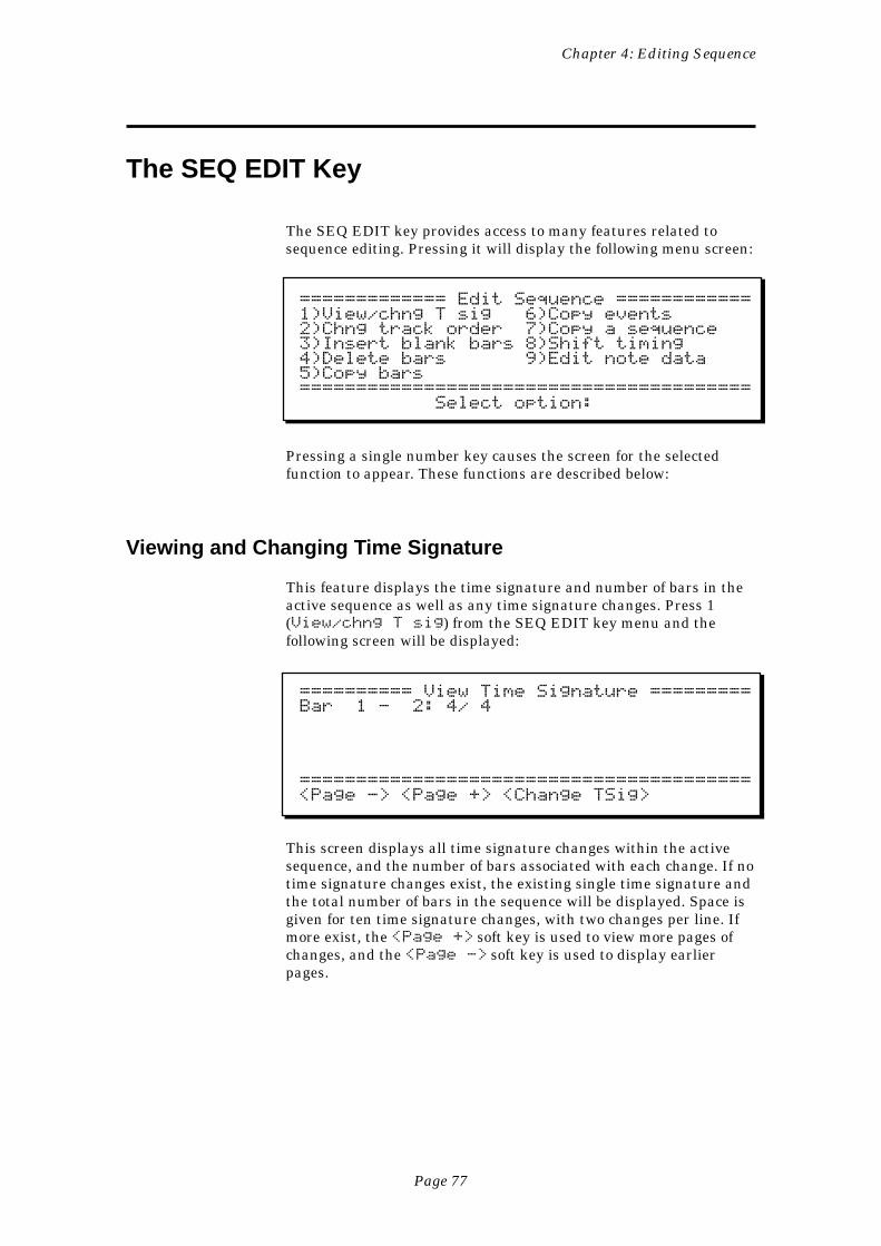
Page 77
Chapter 4: Editing Sequence
The SEQ EDIT Key
The SEQ EDIT key provides access to many features related tosequence editing. Pressing it will display the following menu screen:
============= Edit Sequence ============1)View/chng T sig 6)Copy events2)Chng track order 7)Copy a sequence3)Insert blank bars 8)Shift timing4)Delete bars 9)Edit note data5)Copy bars======================================== Select option:
Pressing a single number key causes the screen for the selectedfunction to appear. These functions are described below:
Viewing and Changing Time Signature
This feature displays the time signature and number of bars in theactive sequence as well as any time signature changes. Press 1(View/chng T sig) from the SEQ EDIT key menu and thefollowing screen will be displayed:
========== View Time Signature =========Bar 1 - 2: 4/ 4
========================================<Page -> <Page +> <Change TSig>
This screen displays all time signature changes within the activesequence, and the number of bars associated with each change. If notime signature changes exist, the existing single time signature andthe total number of bars in the sequence will be displayed. Space isgiven for ten time signature changes, with two changes per line. Ifmore exist, the <Page +> soft key is used to view more pages ofchanges, and the <Page -> soft key is used to display earlierpages.
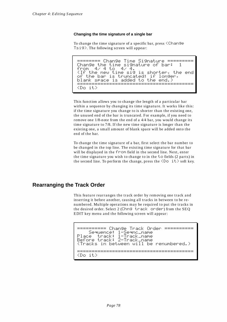
Page 78
Chapter 4: Editing Sequence
Changing the time signature of a single bar
To change the time signature of a specific bar, press <ChangeTsig>. The following screen will appear:
======== Change Time Signature =========Change the time signature of bar: 1from 4/ 4 to 4/ 4.(If the new time sig is shorter, the endof the bar is truncated; if longer,blank space is added to the end.)========================================<Do it>
This function allows you to change the length of a particular barwithin a sequence by changing its time signature. It works like this:if the time signature you change to is shorter than the existing one,the unused end of the bar is truncated. For example, if you need toremove one 1/8-note from the end of a 4/4 bar, you would change itstime signature to 7/8. If the new time signature is longer than theexisting one, a small amount of blank space will be added onto theend of the bar.
To change the time signature of a bar, first select the bar number tobe changed in the top line. The existing time signature for that barwill be displayed in the from field in the second line. Next, enterthe time signature you wish to change to in the to fields (2 parts) inthe second line. To perform the change, press the <Do it> soft key.
Rearranging the Track Order
This feature rearranges the track order by removing one track andinserting it before another, causing all tracks in between to be re-numbered. Multiple operations may be required to put the tracks inthe desired order. Select 2 (Chng track order) from the SEQEDIT key menu and the following screen will appear:
========== Change Track Order ========== Sequence: 1-Seqnc_namePlace track: 1-Track_nameBefore track: 2-Track_name(Tracks in between will be renumbered.)
========================================<Do it>
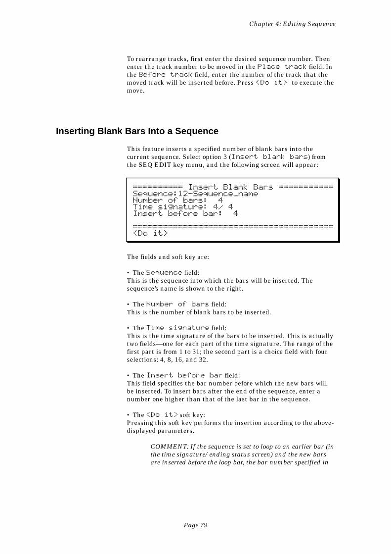
Page 79
Chapter 4: Editing Sequence
To rearrange tracks, first enter the desired sequence number. Thenenter the track number to be moved in the Place track field. Inthe Before track field, enter the number of the track that themoved track will be inserted before. Press <Do it> to execute themove.
Inserting Blank Bars Into a Sequence
This feature inserts a specified number of blank bars into thecurrent sequence. Select option 3 (Insert blank bars) fromthe SEQ EDIT key menu, and the following screen will appear:
========== Insert Blank Bars ===========Sequence:12-Sequence_nameNumber of bars: 4Time signature: 4/ 4Insert before bar: 4
========================================<Do it>
The fields and soft key are:
• The Sequence field:This is the sequence into which the bars will be inserted. Thesequence’s name is shown to the right.
• The Number of bars field:This is the number of blank bars to be inserted.
• The Time signature field:This is the time signature of the bars to be inserted. This is actuallytwo fields—one for each part of the time signature. The range of thefirst part is from 1 to 31; the second part is a choice field with fourselections: 4, 8, 16, and 32.
• The Insert before bar field:This field specifies the bar number before which the new bars willbe inserted. To insert bars after the end of the sequence, enter anumber one higher than that of the last bar in the sequence.
• The <Do it> soft key:Pressing this soft key performs the insertion according to the above-displayed parameters.
COMMENT: If the sequence is set to loop to an earlier bar (inthe time signature/ending status screen) and the new barsare inserted before the loop bar, the bar number specified in
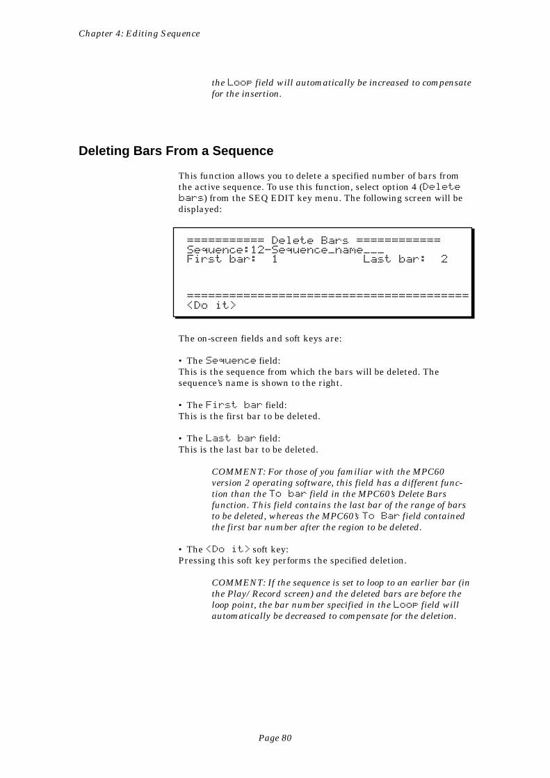
Page 80
Chapter 4: Editing Sequence
the Loop field will automatically be increased to compensatefor the insertion.
Deleting Bars From a Sequence
This function allows you to delete a specified number of bars fromthe active sequence. To use this function, select option 4 (Deletebars) from the SEQ EDIT key menu. The following screen will bedisplayed:
=========== Delete Bars ============Sequence:12-Sequence_name___First bar: 1 Last bar: 2
========================================<Do it>
The on-screen fields and soft keys are:
• The Sequence field:This is the sequence from which the bars will be deleted. Thesequence’s name is shown to the right.
• The First bar field:This is the first bar to be deleted.
• The Last bar field:This is the last bar to be deleted.
COMMENT: For those of you familiar with the MPC60version 2 operating software, this field has a different func-tion than the To bar field in the MPC60’s Delete Barsfunction. This field contains the last bar of the range of barsto be deleted, whereas the MPC60’s To Bar field containedthe first bar number after the region to be deleted.
• The <Do it> soft key:Pressing this soft key performs the specified deletion.
COMMENT: If the sequence is set to loop to an earlier bar (inthe Play/Record screen) and the deleted bars are before theloop point, the bar number specified in the Loop field willautomatically be decreased to compensate for the deletion.
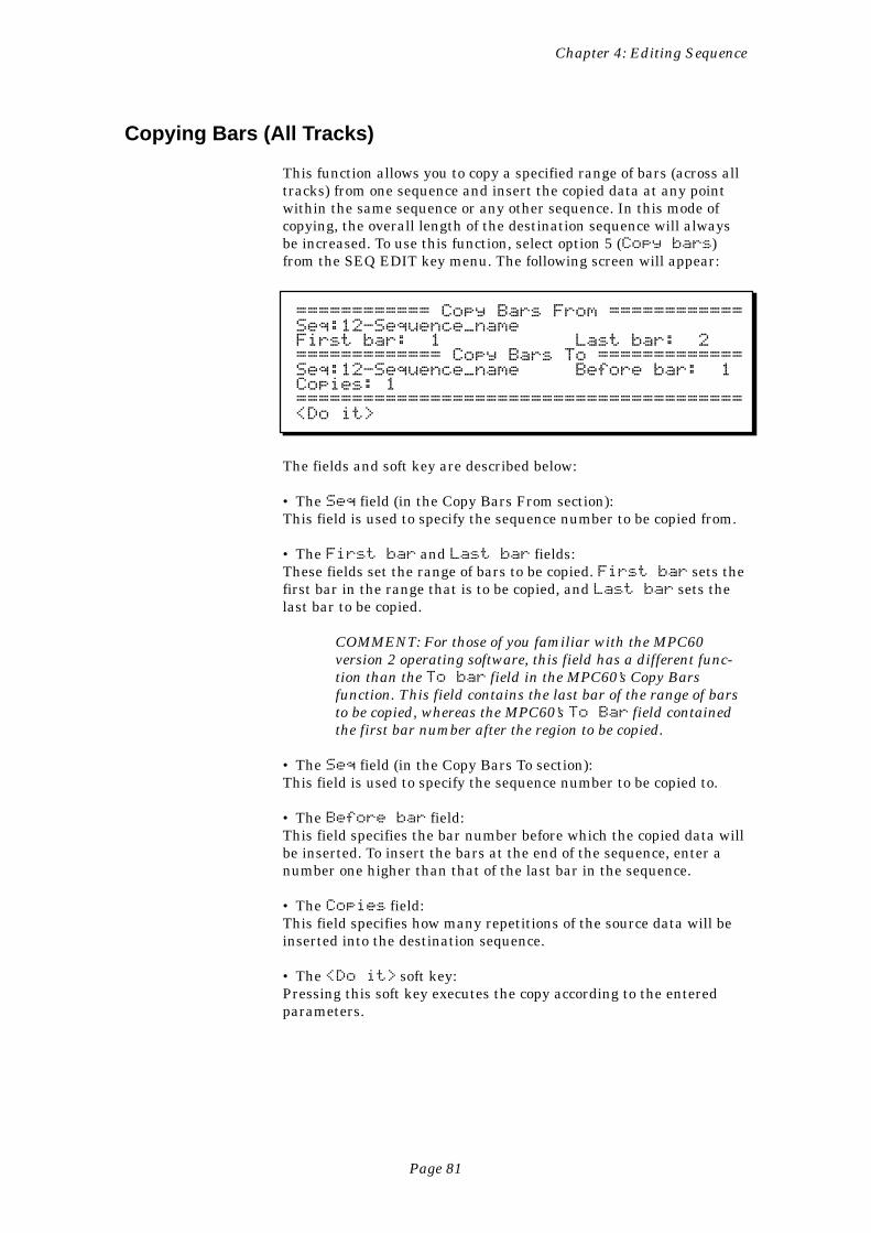
Page 81
Chapter 4: Editing Sequence
Copying Bars (All Tracks)
This function allows you to copy a specified range of bars (across alltracks) from one sequence and insert the copied data at any pointwithin the same sequence or any other sequence. In this mode ofcopying, the overall length of the destination sequence will alwaysbe increased. To use this function, select option 5 (Copy bars)from the SEQ EDIT key menu. The following screen will appear:
============ Copy Bars From ============Seq:12-Sequence_nameFirst bar: 1 Last bar: 2============= Copy Bars To =============Seq:12-Sequence_name Before bar: 1Copies: 1========================================<Do it>
The fields and soft key are described below:
• The Seq field (in the Copy Bars From section):This field is used to specify the sequence number to be copied from.
• The First bar and Last bar fields:These fields set the range of bars to be copied. First bar sets thefirst bar in the range that is to be copied, and Last bar sets thelast bar to be copied.
COMMENT: For those of you familiar with the MPC60version 2 operating software, this field has a different func-tion than the To bar field in the MPC60’s Copy Barsfunction. This field contains the last bar of the range of barsto be copied, whereas the MPC60’s To Bar field containedthe first bar number after the region to be copied.
• The Seq field (in the Copy Bars To section):This field is used to specify the sequence number to be copied to.
• The Before bar field:This field specifies the bar number before which the copied data willbe inserted. To insert the bars at the end of the sequence, enter anumber one higher than that of the last bar in the sequence.
• The Copies field:This field specifies how many repetitions of the source data will beinserted into the destination sequence.
• The <Do it> soft key:Pressing this soft key executes the copy according to the enteredparameters.
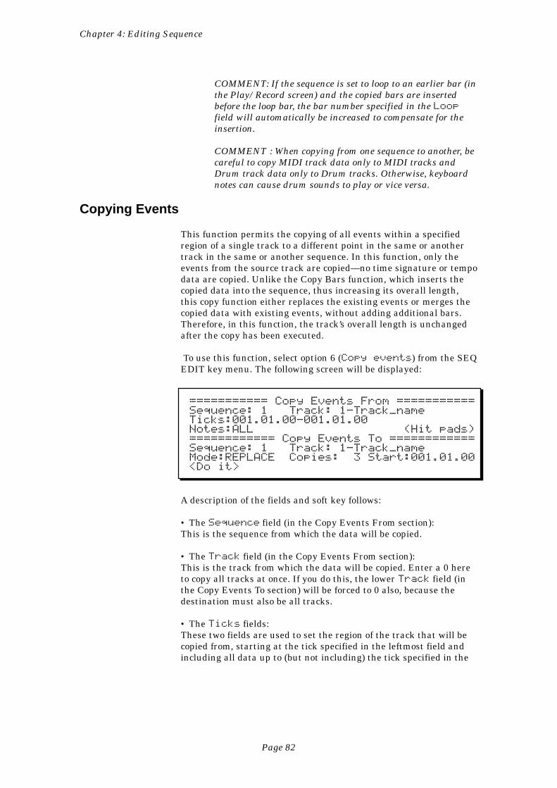
Page 82
Chapter 4: Editing Sequence
COMMENT: If the sequence is set to loop to an earlier bar (inthe Play/Record screen) and the copied bars are insertedbefore the loop bar, the bar number specified in the Loopfield will automatically be increased to compensate for theinsertion.
COMMENT : When copying from one sequence to another, becareful to copy MIDI track data only to MIDI tracks andDrum track data only to Drum tracks. Otherwise, keyboardnotes can cause drum sounds to play or vice versa.
Copying Events
This function permits the copying of all events within a specifiedregion of a single track to a different point in the same or anothertrack in the same or another sequence. In this function, only theevents from the source track are copied—no time signature or tempodata are copied. Unlike the Copy Bars function, which inserts thecopied data into the sequence, thus increasing its overall length,this copy function either replaces the existing events or merges thecopied data with existing events, without adding additional bars.Therefore, in this function, the track’s overall length is unchangedafter the copy has been executed.
To use this function, select option 6 (Copy events) from the SEQEDIT key menu. The following screen will be displayed:
=========== Copy Events From ===========Sequence: 1 Track: 1-Track_nameTicks:001.01.00-001.01.00Notes:ALL (Hit pads)============ Copy Events To ============Sequence: 1 Track: 1-Track_nameMode:REPLACE Copies: 3 Start:001.01.00<Do it>
A description of the fields and soft key follows:
• The Sequence field (in the Copy Events From section):This is the sequence from which the data will be copied.
• The Track field (in the Copy Events From section):This is the track from which the data will be copied. Enter a 0 hereto copy all tracks at once. If you do this, the lower Track field (inthe Copy Events To section) will be forced to 0 also, because thedestination must also be all tracks.
• The Ticks fields:These two fields are used to set the region of the track that will becopied from, starting at the tick specified in the leftmost field andincluding all data up to (but not including) the tick specified in the
Page 83
Chapter 4: Editing Sequence
rightmost field. These are bar.beat.tick fields, enabling you tospecify the region in units as small as one tick.
• The Notes field:This field determines which notes will be copied. It appears in one oftwo ways depending on whether the selected track is a Drum trackor a MIDI track:
1. If the source track is a Drum track, this field is used toselect the specific drum notes, represented as MIDI notenumbers, that are to be copied. It cannot be accessed withthe cursor; notes can only be entered by pressing pads orvia the reception of external MIDI notes. When thescreen is first displayed, it contains the word ALL (copyall notes) and the text (Hit pads) to the right. Whena pad is pressed, the pad’s currently assigned notenumber appears in the field, followed by the pad numberand currently assigned sound name. On the right side ofthe line is the text ( 1 pad ) indicating that 1 pad isselected for copying:
Notes:36/A02-SNARE_DRUM ( 1 pad )
If another pad is pressed, its note number, pad number,and assigned sound are displayed instead, and the text tothe right displays ( 2 pads). This continues until theuser has selected all of the pads he or she intends to copy.
2. If the source track is a MIDI track, two numeric fields—used to set the lowest and highest notes of the note rangethat is to be erased—will appear. Each of these numericfields is editable via the cursor and has a range of 0 to127; the equivalent note name (C-2 to G8) is shown to theright of each field. Alternately, these fields can be set bypressing two notes on the MIDI input device’s keyboard.The fields will automatically be set to the lowest andhighest keys pressed.
• The Sequence field (in the Copy Events To section):This is the sequence into which the data will be copied.
• The Track field (in the Copy Events To section):This is the track to be copied to. If this field can’t be changed from0—(all tracks), then the upper Track field (in the CopyEvents From section) must have been set to 0, indicating that alltracks will be copied.
• The Mode field:This is a choice field with two options:
1. REPLACE:In this mode, all existing events in the destination trackare overwritten by the newly copied data.
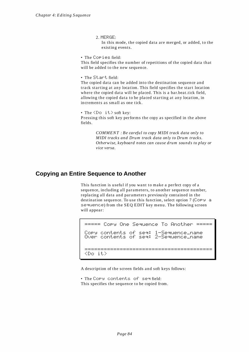
Page 84
Chapter 4: Editing Sequence
2. MERGE:In this mode, the copied data are merged, or added, to theexisting events.
• The Copies field:This field specifies the number of repetitions of the copied data thatwill be added to the new sequence.
• The Start field:The copied data can be added into the destination sequence andtrack starting at any location. This field specifies the start locationwhere the copied data will be placed. This is a bar.beat.tick field,allowing the copied data to be placed starting at any location, inincrements as small as one tick.
• The <Do it> soft key:Pressing this soft key performs the copy as specified in the abovefields.
COMMENT : Be careful to copy MIDI track data only toMIDI tracks and Drum track data only to Drum tracks.Otherwise, keyboard notes can cause drum sounds to play orvice versa.
Copying an Entire Sequence to Another
This function is useful if you want to make a perfect copy of asequence, including all parameters, to another sequence number,replacing all data and parameters previously contained in thedestination sequence. To use this function, select option 7 (Copy asequence) from the SEQ EDIT key menu. The following screenwill appear:
===== Copy One Sequence To Another =====
Copy contents of seq: 1-Sequence_nameOver contents of seq: 2-Sequence_name
========================================<Do it>
A description of the screen fields and soft keys follows:
• The Copy contents of seq field:This specifies the sequence to be copied from.
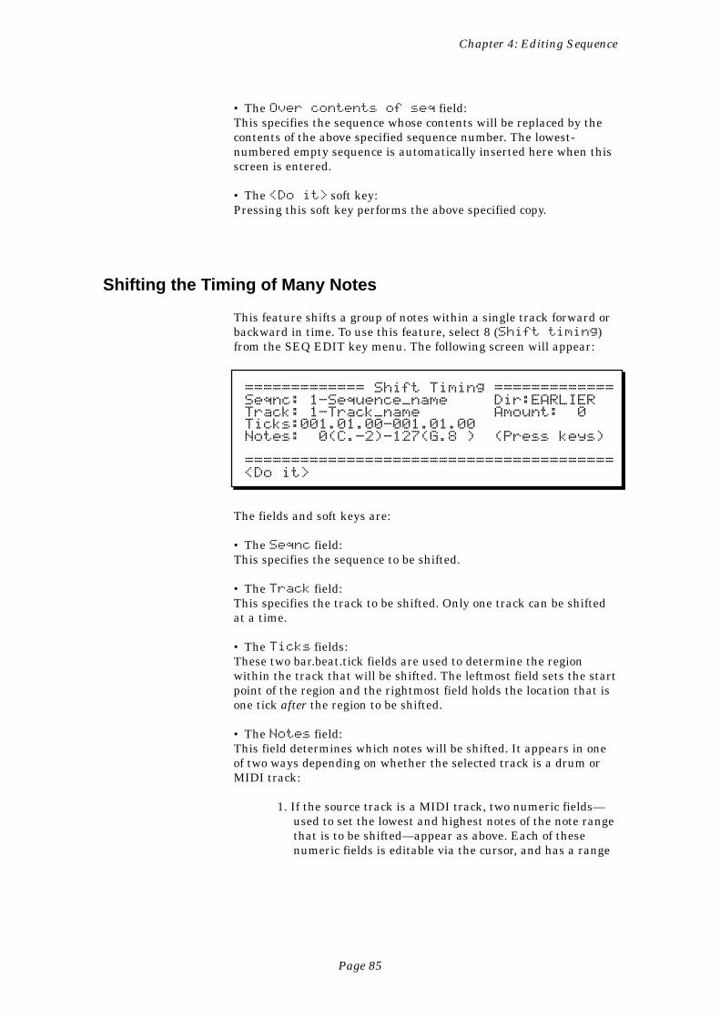
Page 85
Chapter 4: Editing Sequence
• The Over contents of seq field:This specifies the sequence whose contents will be replaced by thecontents of the above specified sequence number. The lowest-numbered empty sequence is automatically inserted here when thisscreen is entered.
• The <Do it> soft key:Pressing this soft key performs the above specified copy.
Shifting the Timing of Many Notes
This feature shifts a group of notes within a single track forward orbackward in time. To use this feature, select 8 (Shift timing)from the SEQ EDIT key menu. The following screen will appear:
============= Shift Timing =============Seqnc: 1-Sequence_name Dir:EARLIERTrack: 1-Track_name Amount: 0Ticks:001.01.00-001.01.00Notes: 0(C.-2)-127(G.8 ) (Press keys)
========================================<Do it>
The fields and soft keys are:
• The Seqnc field:This specifies the sequence to be shifted.
• The Track field:This specifies the track to be shifted. Only one track can be shiftedat a time.
• The Ticks fields:These two bar.beat.tick fields are used to determine the regionwithin the track that will be shifted. The leftmost field sets the startpoint of the region and the rightmost field holds the location that isone tick after the region to be shifted.
• The Notes field:This field determines which notes will be shifted. It appears in oneof two ways depending on whether the selected track is a drum orMIDI track:
1. If the source track is a MIDI track, two numeric fields—used to set the lowest and highest notes of the note rangethat is to be shifted—appear as above. Each of thesenumeric fields is editable via the cursor, and has a range
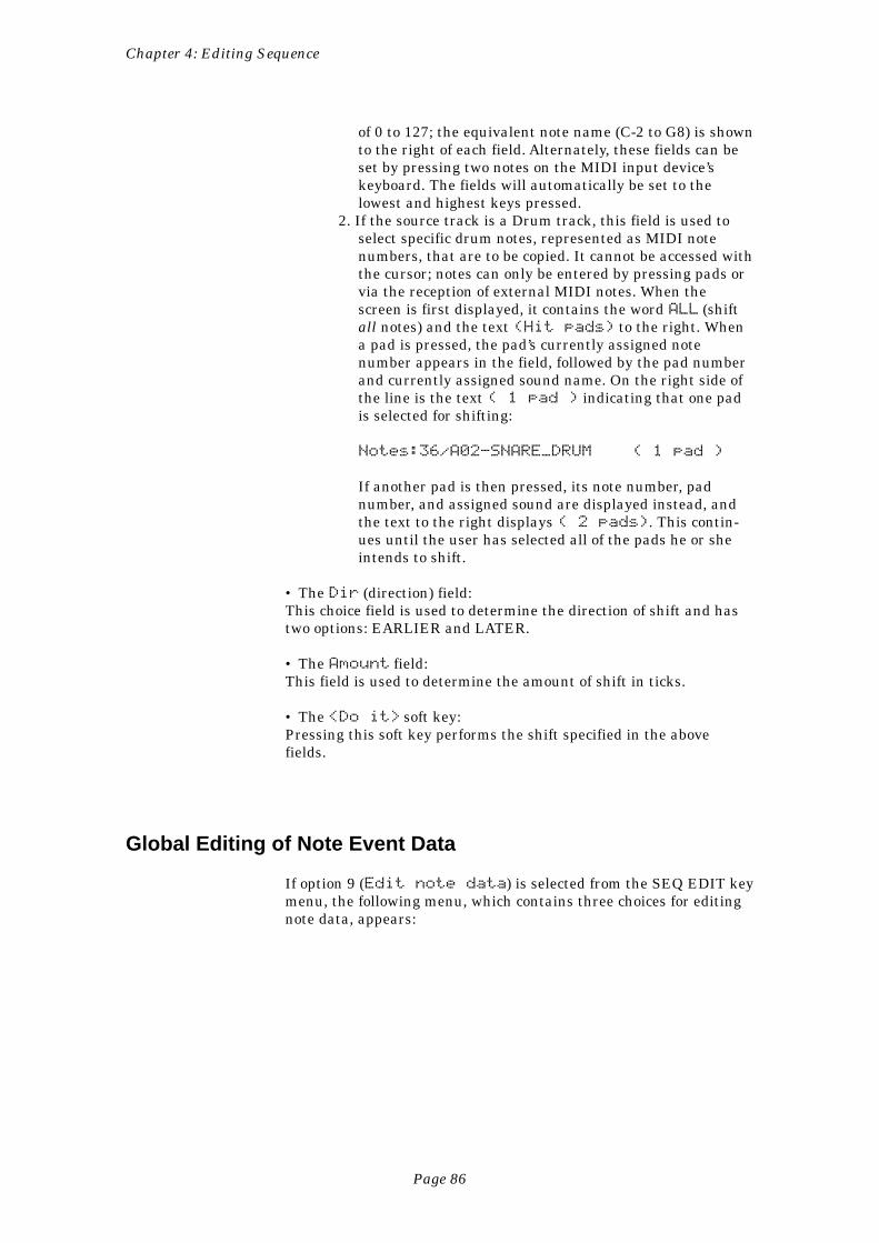
Page 86
Chapter 4: Editing Sequence
of 0 to 127; the equivalent note name (C-2 to G8) is shownto the right of each field. Alternately, these fields can beset by pressing two notes on the MIDI input device’skeyboard. The fields will automatically be set to thelowest and highest keys pressed.
2. If the source track is a Drum track, this field is used toselect specific drum notes, represented as MIDI notenumbers, that are to be copied. It cannot be accessed withthe cursor; notes can only be entered by pressing pads orvia the reception of external MIDI notes. When thescreen is first displayed, it contains the word ALL (shiftall notes) and the text (Hit pads) to the right. Whena pad is pressed, the pad’s currently assigned notenumber appears in the field, followed by the pad numberand currently assigned sound name. On the right side ofthe line is the text ( 1 pad ) indicating that one padis selected for shifting:
Notes:36/A02-SNARE_DRUM ( 1 pad )
If another pad is then pressed, its note number, padnumber, and assigned sound are displayed instead, andthe text to the right displays ( 2 pads). This contin-ues until the user has selected all of the pads he or sheintends to shift.
• The Dir (direction) field:This choice field is used to determine the direction of shift and hastwo options: EARLIER and LATER.
• The Amount field:This field is used to determine the amount of shift in ticks.
• The <Do it> soft key:Pressing this soft key performs the shift specified in the abovefields.
Global Editing of Note Event Data
If option 9 (Edit note data) is selected from the SEQ EDIT keymenu, the following menu, which contains three choices for editingnote data, appears:
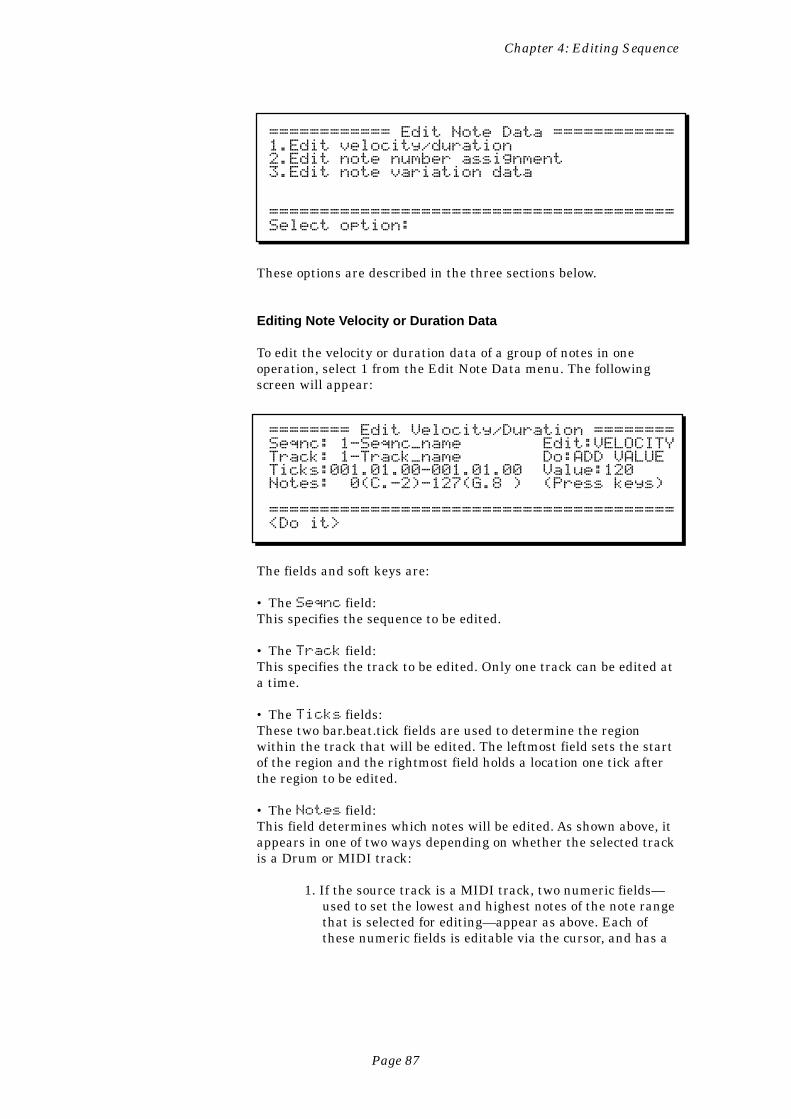
Page 87
Chapter 4: Editing Sequence
============ Edit Note Data ============1.Edit velocity/duration2.Edit note number assignment3.Edit note variation data
========================================Select option:
These options are described in the three sections below.
Editing Note Velocity or Duration Data
To edit the velocity or duration data of a group of notes in oneoperation, select 1 from the Edit Note Data menu. The followingscreen will appear:
======== Edit Velocity/Duration ========Seqnc: 1-Seqnc_name Edit:VELOCITYTrack: 1-Track_name Do:ADD VALUETicks:001.01.00-001.01.00 Value:120Notes: 0(C.-2)-127(G.8 ) (Press keys)
========================================<Do it>
The fields and soft keys are:
• The Seqnc field:This specifies the sequence to be edited.
• The Track field:This specifies the track to be edited. Only one track can be edited ata time.
• The Ticks fields:These two bar.beat.tick fields are used to determine the regionwithin the track that will be edited. The leftmost field sets the startof the region and the rightmost field holds a location one tick afterthe region to be edited.
• The Notes field:This field determines which notes will be edited. As shown above, itappears in one of two ways depending on whether the selected trackis a Drum or MIDI track:
1. If the source track is a MIDI track, two numeric fields—used to set the lowest and highest notes of the note rangethat is selected for editing—appear as above. Each ofthese numeric fields is editable via the cursor, and has a
Page 88
Chapter 4: Editing Sequence
range of 0 to 127; the equivalent note name (C-2 to G8) isshown to the right of each field. Alternately, these fieldscan be set by pressing two notes on the MIDI inputdevice’s keyboard. The fields will automatically be set tothe lowest and highest keys pressed.
2. If the source track is a Drum track, this field is used toselect specific drum notes, represented by MIDI notenumbers, that are to be edited. This field cannot beaccessed by the cursor—it can only be changed by press-ing pads or receiving external MIDI notes. When thescreen is first displayed, it contains the word ALL (editall notes) and the text (Hit pads) to the right. Whena pad is pressed, the pad’s currently assigned notenumber appears in the field, followed by the pad numberand currently-assigned sound name. On the right side ofthe line is the text ( 1 pad ) indicating that one padis selected for editing:
Notes:36/A02-SNARE_DRUM ( 1 pad )
If another pad is then pressed, its note number, padnumber, and assigned sound are displayed instead, andthe text to the right displays ( 2 pads). This contin-ues until the user has selected all of the pads he or sheintends to edit.
• The Edit field:This is a choice field with two options: VELOCITY and DURATION.It is used to select which of these two parameters will be affected.
• The Do field:This is a choice field with four options:
1. ADD VALUE: This selection adds the number in theValue field to the velocity or duration of each note thathas been selected for editing.
2. SUB VALUE: This selection subtracts the number in theValue field from the velocity or duration of each notethat has been selected for editing.
3. MULT VAL %: This selection multiplies the velocity orduration of each note that has been selected for editing bythe number in the Value field. A value of 100% = nochange; values of 101 to 200% proportionally increaseeach note’s velocity or duration value; values of 0 to 99%proportionally decrease each note’s velocity or durationvalue.
4. SET TO VAL: This selection changes the velocity orduration of each note that has been selected for editing tothe number in the Value field.
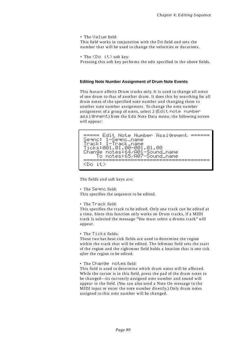
Page 89
Chapter 4: Editing Sequence
• The Value field:This field works in conjunction with the Do field and sets thenumber that will be used to change the velocities or durations.
• The <Do it> soft key:Pressing this soft key performs the edit specified in the above fields.
Editing Note Number Assignment of Drum Note Events
This feature affects Drum tracks only. It is used to change all notesof one drum to that of another drum. It does this by searching for alldrum notes of the specified note number and changing them toanother note number assignment. To change the note numberassignment of a group of notes, select 2 (Edit note numberassignment) from the Edit Note Data menu; the following screenwill appear:
===== Edit Note Number Assignment ======Seqnc: 1-Seqnc_nameTrack: 1-Track_nameTicks:001.01.00-001.01.00Change notes:64/A01-Sound_name To notes:65/A07-Sound_name========================================<Do it>
The fields and soft keys are:
• The Seqnc field:This specifies the sequence to be edited.
• The Track field:This specifies the track to be edited. Only one track can be edited ata time. Since this function only works on Drum tracks, if a MIDItrack is selected the message “You must select a drums track” willappear.
• The Ticks fields:These two bar.beat.tick fields are used to determine the regionwithin the track that will be edited. The leftmost field sets the startof the region and the rightmost field holds a location that is one tickafter the region to be edited.
• The Change notes field:This field is used to determine which drum notes will be affected.While the cursor is in this field, press the pad of the drum notes tobe changed—its currently assigned note number and sound willappear in the field. (You can also send a Note On message to theMIDI input or enter the note number directly.) Only drum notesassigned to this note number will be changed.
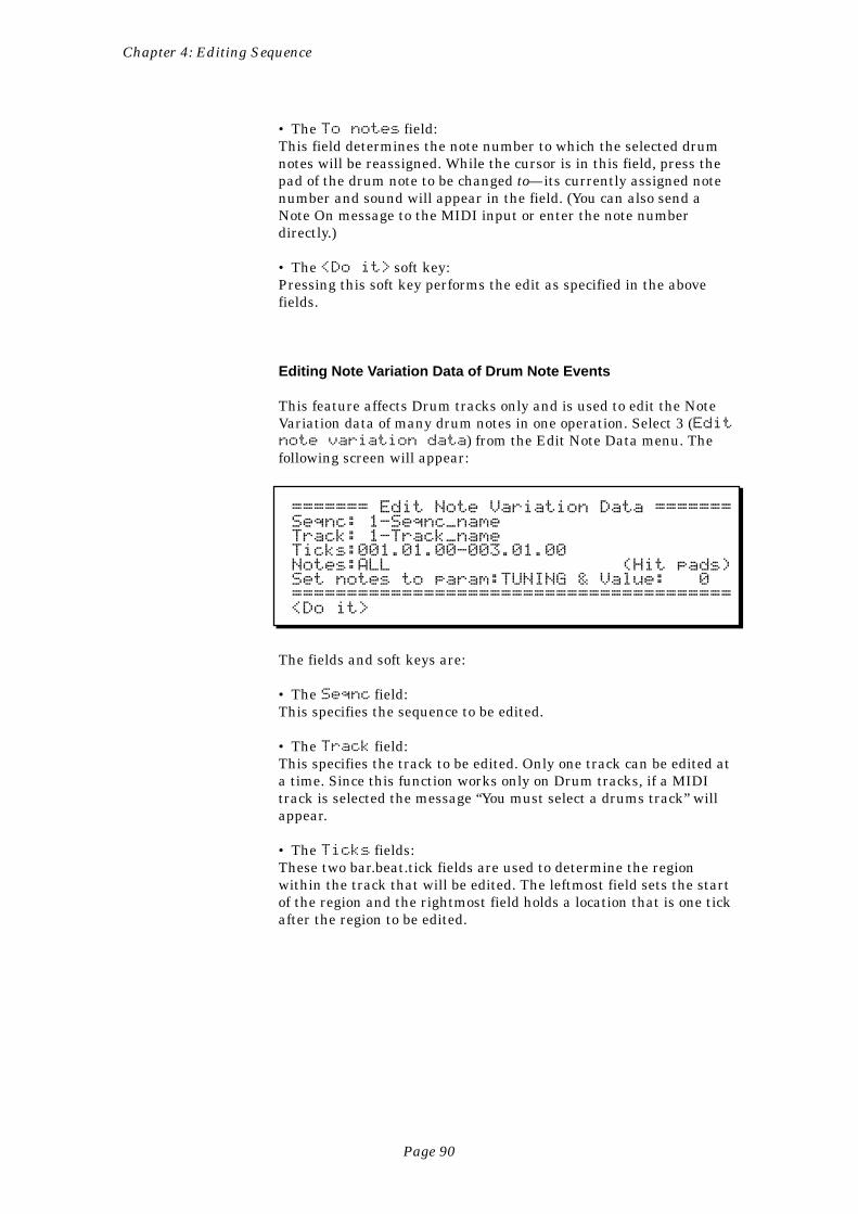
Page 90
Chapter 4: Editing Sequence
• The To notes field:This field determines the note number to which the selected drumnotes will be reassigned. While the cursor is in this field, press thepad of the drum note to be changed to—its currently assigned notenumber and sound will appear in the field. (You can also send aNote On message to the MIDI input or enter the note numberdirectly.)
• The <Do it> soft key:Pressing this soft key performs the edit as specified in the abovefields.
Editing Note Variation Data of Drum Note Events
This feature affects Drum tracks only and is used to edit the NoteVariation data of many drum notes in one operation. Select 3 (Editnote variation data) from the Edit Note Data menu. Thefollowing screen will appear:
======= Edit Note Variation Data =======Seqnc: 1-Seqnc_nameTrack: 1-Track_nameTicks:001.01.00-003.01.00Notes:ALL (Hit pads)Set notes to param:TUNING & Value: 0========================================<Do it>
The fields and soft keys are:
• The Seqnc field:This specifies the sequence to be edited.
• The Track field:This specifies the track to be edited. Only one track can be edited ata time. Since this function works only on Drum tracks, if a MIDItrack is selected the message “You must select a drums track” willappear.
• The Ticks fields:These two bar.beat.tick fields are used to determine the regionwithin the track that will be edited. The leftmost field sets the startof the region and the rightmost field holds a location that is one tickafter the region to be edited.
Page 91
Chapter 4: Editing Sequence
• The Notes field:This field determines which notes will be affected. It cannot beaccessed by the cursor. It can only be changed by pressing pads orreceiving external MIDI notes. When the screen is first displayed, itappears as shown above with the word ALL (affect all notes) and thetext (Hit pads) to the right. When a pad is pressed, the pad’scurrently assigned note number appears in the field, followed by thepad number and currently assigned sound name. On the right sideof the line is the text ( 1 pad ) indicating that one pad is se-lected for editing:
Notes:36/A02-SNARE_DRUM ( 1 pad )
If another pad is then pressed, its note number, pad number, andassigned sound are displayed instead, and the text to the rightdisplays ( 2 pads). This continues until the user has selected allof the pads he or she intends to edit.
• The Set notes to param field:This choice field determines to which parameter (TUNING, AT-TACK, DECAY, or FILTER) the selected notes’ Note Variationparameter will be set.
• The Value field:This field selects what value of tuning, attack, decay, or filter theselected notes’ Note Variation data will be set to.
• The <Do it> soft key:Pressing this key performs the edit as specified in the above fields.
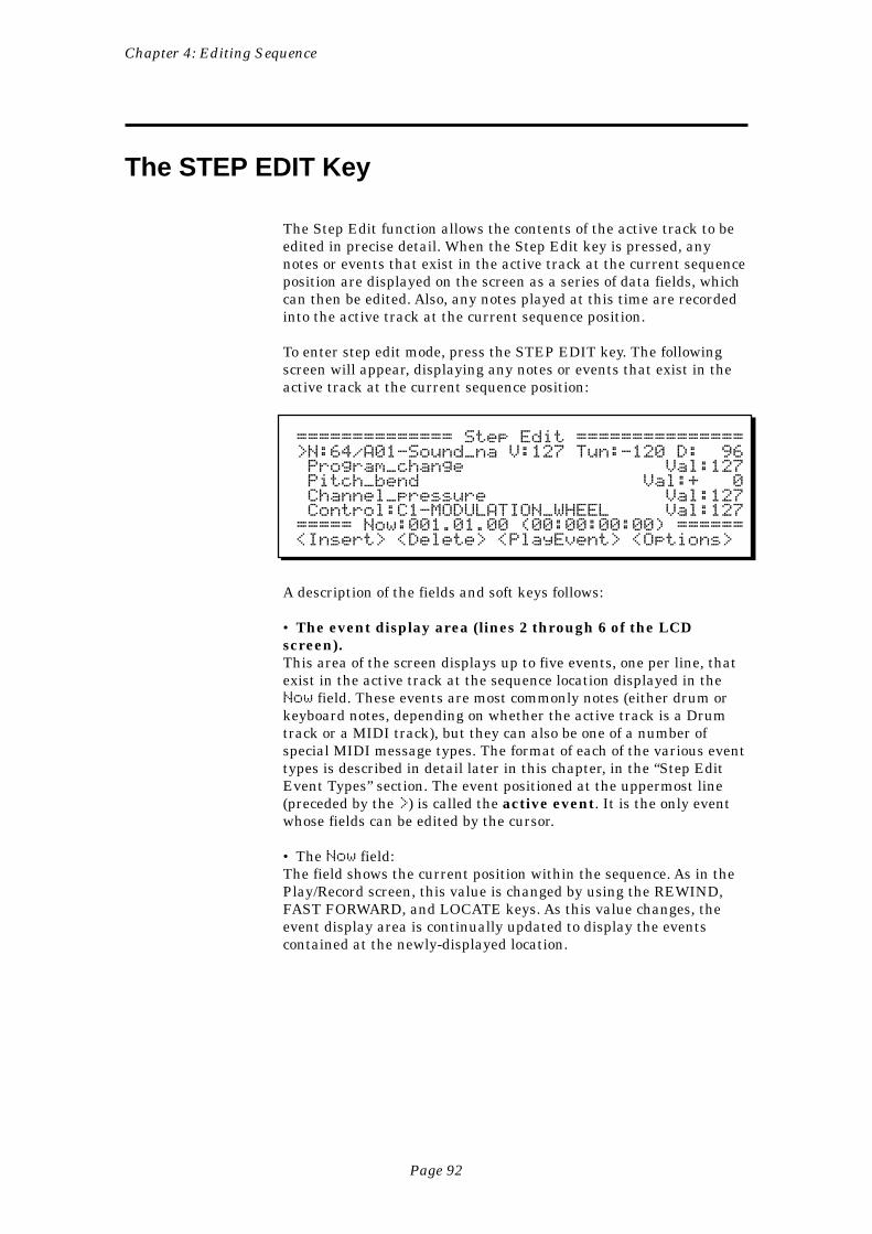
Page 92
Chapter 4: Editing Sequence
The STEP EDIT Key
The Step Edit function allows the contents of the active track to beedited in precise detail. When the Step Edit key is pressed, anynotes or events that exist in the active track at the current sequenceposition are displayed on the screen as a series of data fields, whichcan then be edited. Also, any notes played at this time are recordedinto the active track at the current sequence position.
To enter step edit mode, press the STEP EDIT key. The followingscreen will appear, displaying any notes or events that exist in theactive track at the current sequence position:
============== Step Edit ===============>N:64/A01-Sound_na V:127 Tun:-120 D: 96 Program_change Val:127 Pitch_bend Val:+ 0 Channel_pressure Val:127 Control:C1-MODULATION_WHEEL Val:127===== Now:001.01.00 (00:00:00:00) ======<Insert> <Delete> <PlayEvent> <Options>
A description of the fields and soft keys follows:
• The event display area (lines 2 through 6 of the LCDscreen).This area of the screen displays up to five events, one per line, thatexist in the active track at the sequence location displayed in theNow field. These events are most commonly notes (either drum orkeyboard notes, depending on whether the active track is a Drumtrack or a MIDI track), but they can also be one of a number ofspecial MIDI message types. The format of each of the various eventtypes is described in detail later in this chapter, in the “Step EditEvent Types” section. The event positioned at the uppermost line(preceded by the >) is called the active event. It is the only eventwhose fields can be edited by the cursor.
• The Now field:The field shows the current position within the sequence. As in thePlay/Record screen, this value is changed by using the REWIND,FAST FORWARD, and LOCATE keys. As this value changes, theevent display area is continually updated to display the eventscontained at the newly-displayed location.
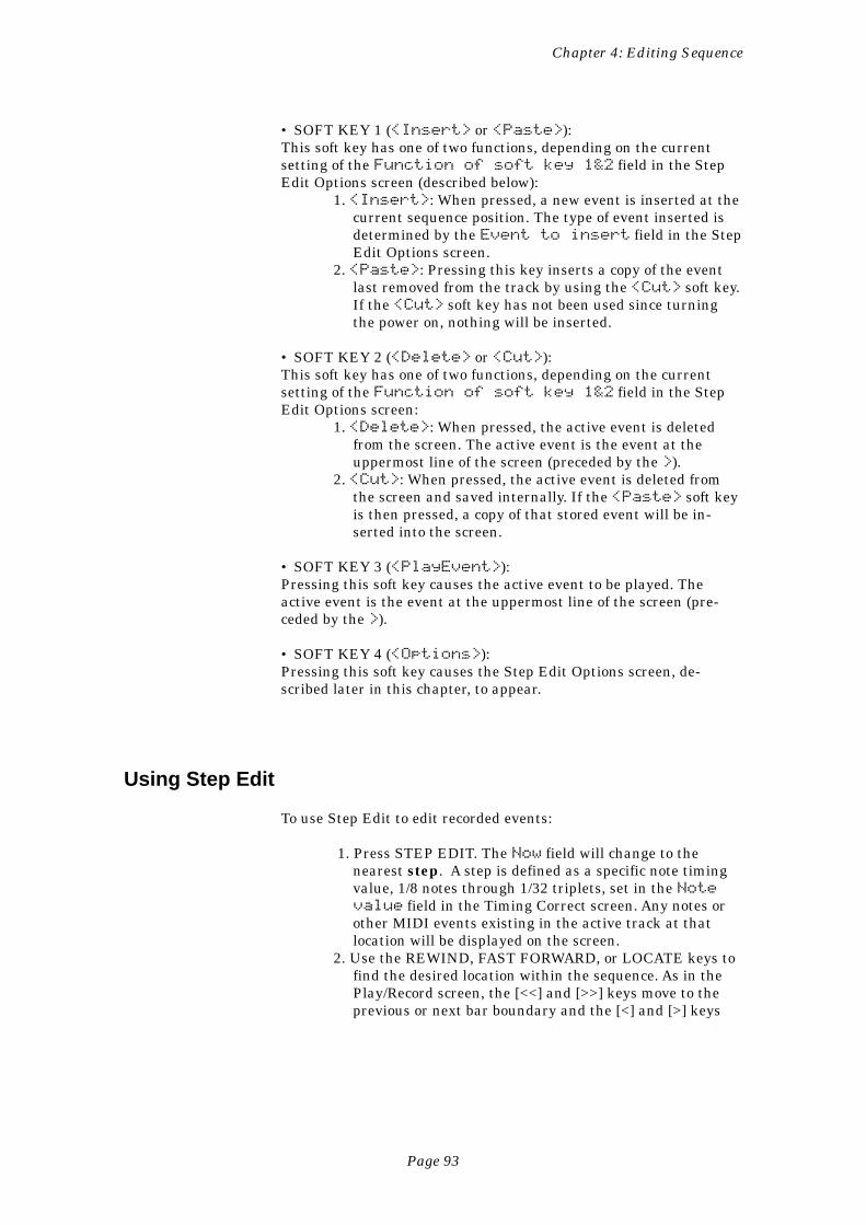
Page 93
Chapter 4: Editing Sequence
• SOFT KEY 1 (<Insert> or <Paste>):This soft key has one of two functions, depending on the currentsetting of the Function of soft key 1&2 field in the StepEdit Options screen (described below):
1. <Insert>: When pressed, a new event is inserted at thecurrent sequence position. The type of event inserted isdetermined by the Event to insert field in the StepEdit Options screen.
2. <Paste>: Pressing this key inserts a copy of the eventlast removed from the track by using the <Cut> soft key.If the <Cut> soft key has not been used since turningthe power on, nothing will be inserted.
• SOFT KEY 2 (<Delete> or <Cut>):This soft key has one of two functions, depending on the currentsetting of the Function of soft key 1&2 field in the StepEdit Options screen:
1. <Delete>: When pressed, the active event is deletedfrom the screen. The active event is the event at theuppermost line of the screen (preceded by the >).
2. <Cut>: When pressed, the active event is deleted fromthe screen and saved internally. If the <Paste> soft keyis then pressed, a copy of that stored event will be in-serted into the screen.
• SOFT KEY 3 (<PlayEvent>):Pressing this soft key causes the active event to be played. Theactive event is the event at the uppermost line of the screen (pre-ceded by the >).
• SOFT KEY 4 (<Options>):Pressing this soft key causes the Step Edit Options screen, de-scribed later in this chapter, to appear.
Using Step Edit
To use Step Edit to edit recorded events:
1. Press STEP EDIT. The Now field will change to thenearest step. A step is defined as a specific note timingvalue, 1/8 notes through 1/32 triplets, set in the Notevalue field in the Timing Correct screen. Any notes orother MIDI events existing in the active track at thatlocation will be displayed on the screen.
2. Use the REWIND, FAST FORWARD, or LOCATE keys tofind the desired location within the sequence. As in thePlay/Record screen, the [<<] and [>>] keys move to theprevious or next bar boundary and the [<] and [>] keys
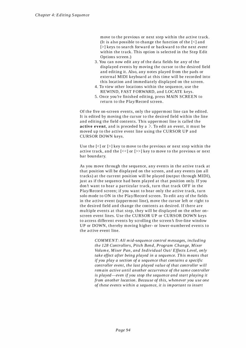
Page 94
Chapter 4: Editing Sequence
move to the previous or next step within the active track.(It is also possible to change the function of the [<] and[>] keys to search forward or backward to the next eventwithin the track. This option is selected in the Step EditOptions screen.)
3. You can now edit any of the data fields for any of thedisplayed events by moving the cursor to the desired fieldand editing it. Also, any notes played from the pads orexternal MIDI keyboard at this time will be recorded intothis location and immediately displayed on the screen.
4. To view other locations within the sequence, use theREWIND, FAST FORWARD, and LOCATE keys.
5. Once you’re finished editing, press MAIN SCREEN toreturn to the Play/Record screen.
Of the five on-screen events, only the uppermost line can be edited.It is edited by moving the cursor to the desired field within the lineand editing the field contents. This uppermost line is called theactive event, and is preceded by a >. To edit an event, it must bemoved up to the active event line using the CURSOR UP andCURSOR DOWN keys.
Use the [<] or [>] key to move to the previous or next step within theactive track, and the [<<] or [>>] key to move to the previous or nextbar boundary.
As you move through the sequence, any events in the active track atthat position will be displayed on the screen, and any events (on alltracks) at the current position will be played (output through MIDI),just as if the sequence had been played at that position only. If youdon’t want to hear a particular track, turn that track OFF in thePlay/Record screen; if you want to hear only the active track, turnsolo mode to ON in the Play/Record screen. To edit any of the fieldsin the active event (uppermost line), move the cursor left or right tothe desired field and change the contents as desired. If there aremultiple events at that step, they will be displayed on the other on-screen event lines. Use the CURSOR UP or CURSOR DOWN keysto access different events by scrolling the screen’s five-line windowUP or DOWN, thereby moving higher- or lower-numbered events tothe active event line.
COMMENT: All mid-sequence control messages, includingthe 128 Controllers, Pitch Bend, Program Change, MixerVolume, Mixer Pan, and Individual Out/Effects Level, onlytake effect after being played in a sequence. This means thatif you play a section of a sequence that contains a specificcontroller event, the last played value of that controller willremain active until another occurrence of the same controlleris played—even if you stop the sequence and start playing itfrom another location. Because of this, whenever you use oneof these events within a sequence, it is important to insert
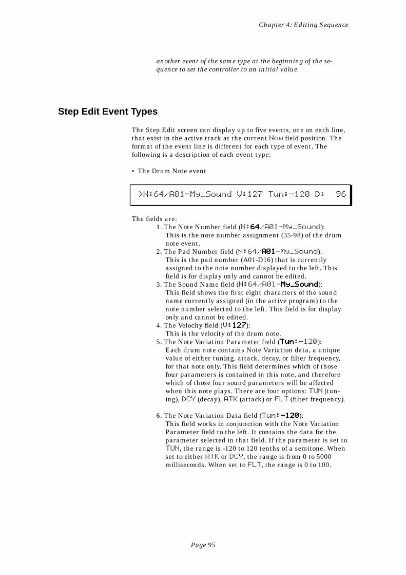
Page 95
Chapter 4: Editing Sequence
another event of the same type at the beginning of the se-quence to set the controller to an initial value.
Step Edit Event Types
The Step Edit screen can display up to five events, one on each line,that exist in the active track at the current Now field position. Theformat of the event line is different for each type of event. Thefollowing is a description of each event type:
• The Drum Note event
>N:64/A01-My_Sound V:127 Tun:-120 D: 96
The fields are:1. The Note Number field (N:6464646464/A01-My_Sound):
This is the note number assignment (35-98) of the drumnote event.
2. The Pad Number field (N:64/A01A01A01A01A01-My_Sound):This is the pad number (A01-D16) that is currentlyassigned to the note number displayed to the left. Thisfield is for display only and cannot be edited.
3. The Sound Name field (N:64/A01-My_SoundMy_SoundMy_SoundMy_SoundMy_Sound):This field shows the first eight characters of the soundname currently assigned (in the active program) to thenote number selected to the left. This field is for displayonly and cannot be edited.
4. The Velocity field (V:127127127127127):This is the velocity of the drum note.
5. The Note Variation Parameter field (TunTunTunTunTun:-120):Each drum note contains Note Variation data, a uniquevalue of either tuning, attack, decay, or filter frequency,for that note only. This field determines which of thosefour parameters is contained in this note, and thereforewhich of those four sound parameters will be affectedwhen this note plays. There are four options: TUN (tun-ing), DCY (decay), ATK (attack) or FLT (filter frequency).
6. The Note Variation Data field (Tun:-120-120-120-120-120):This field works in conjunction with the Note VariationParameter field to the left. It contains the data for theparameter selected in that field. If the parameter is set toTUN, the range is -120 to 120 tenths of a semitone. Whenset to either ATK or DCY, the range is from 0 to 5000milliseconds. When set to FLT, the range is 0 to 100.
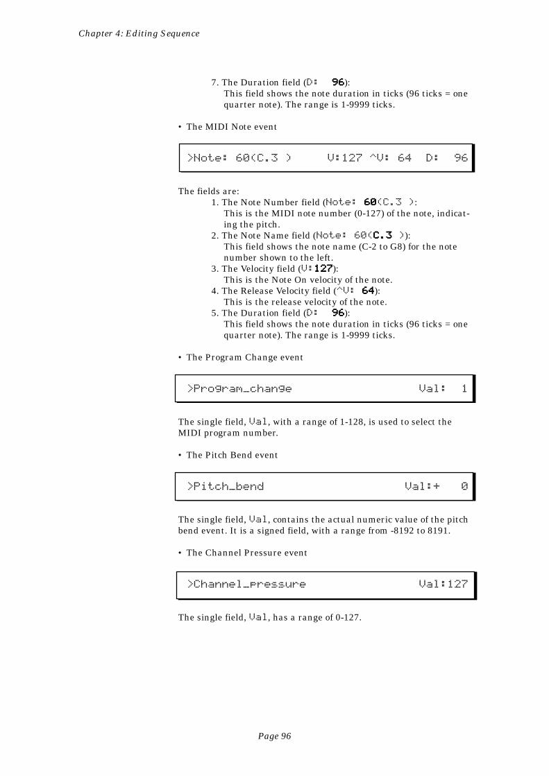
Page 96
Chapter 4: Editing Sequence
7. The Duration field (D: 9696969696):This field shows the note duration in ticks (96 ticks = onequarter note). The range is 1-9999 ticks.
• The MIDI Note event
>Note: 60(C.3 ) V:127 ^V: 64 D: 96
The fields are:1. The Note Number field (Note: 60 60 60 60 60(C.3 ):
This is the MIDI note number (0-127) of the note, indicat-ing the pitch.
2. The Note Name field (Note: 60(C.3 C.3 C.3 C.3 C.3 )):This field shows the note name (C-2 to G8) for the notenumber shown to the left.
3. The Velocity field (V:127127127127127):This is the Note On velocity of the note.
4. The Release Velocity field (^V: 64 64 64 64 64):This is the release velocity of the note.
5. The Duration field (D: 9696969696):This field shows the note duration in ticks (96 ticks = onequarter note). The range is 1-9999 ticks.
• The Program Change event
>Program_change Val: 1
The single field, Val, with a range of 1-128, is used to select theMIDI program number.
• The Pitch Bend event
>Pitch_bend Val:+ 0
The single field, Val, contains the actual numeric value of the pitchbend event. It is a signed field, with a range from -8192 to 8191.
• The Channel Pressure event
>Channel_pressure Val:127
The single field, Val, has a range of 0-127.
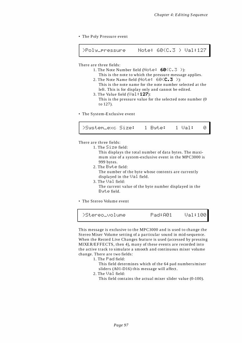
Page 97
Chapter 4: Editing Sequence
• The Poly Pressure event
>Poly_pressure Note: 60(C.3 ) Val:127
There are three fields:1. The Note Number field (Note: 60 60 60 60 60(C.3 )):
This is the note to which the pressure message applies.2. The Note Name field (Note: 60<C.3 C.3 C.3 C.3 C.3 )):
This is the note name for the note number selected at theleft. This is for display only and cannot be edited.
3. The Value field (Val:127127127127127):This is the pressure value for the selected note number (0to 127).
• The System-Exclusive event
>System_exc Size: 1 Byte: 1 Val: 0
There are three fields:1. The Size field:
This displays the total number of data bytes. The maxi-mum size of a system-exclusive event in the MPC3000 is999 bytes.
2. The Byte field:The number of the byte whose contents are currentlydisplayed in the Val field.
3. The Val field:The current value of the byte number displayed in theByte field.
• The Stereo Volume event
>Stereo_volume Pad:A01 Val:100
This message is exclusive to the MPC3000 and is used to change theStereo Mixer Volume setting of a particular sound in mid-sequence.When the Record Live Changes feature is used (accessed by pressingMIXER/EFFECTS, then 4), many of these events are recorded intothe active track to simulate a smooth and continuous mixer volumechange. There are two fields:
1. The Pad field:This field determines which of the 64 pad numbers/mixersliders (A01-D16) this message will affect.
2. The Val field:This field contains the actual mixer slider value (0-100).
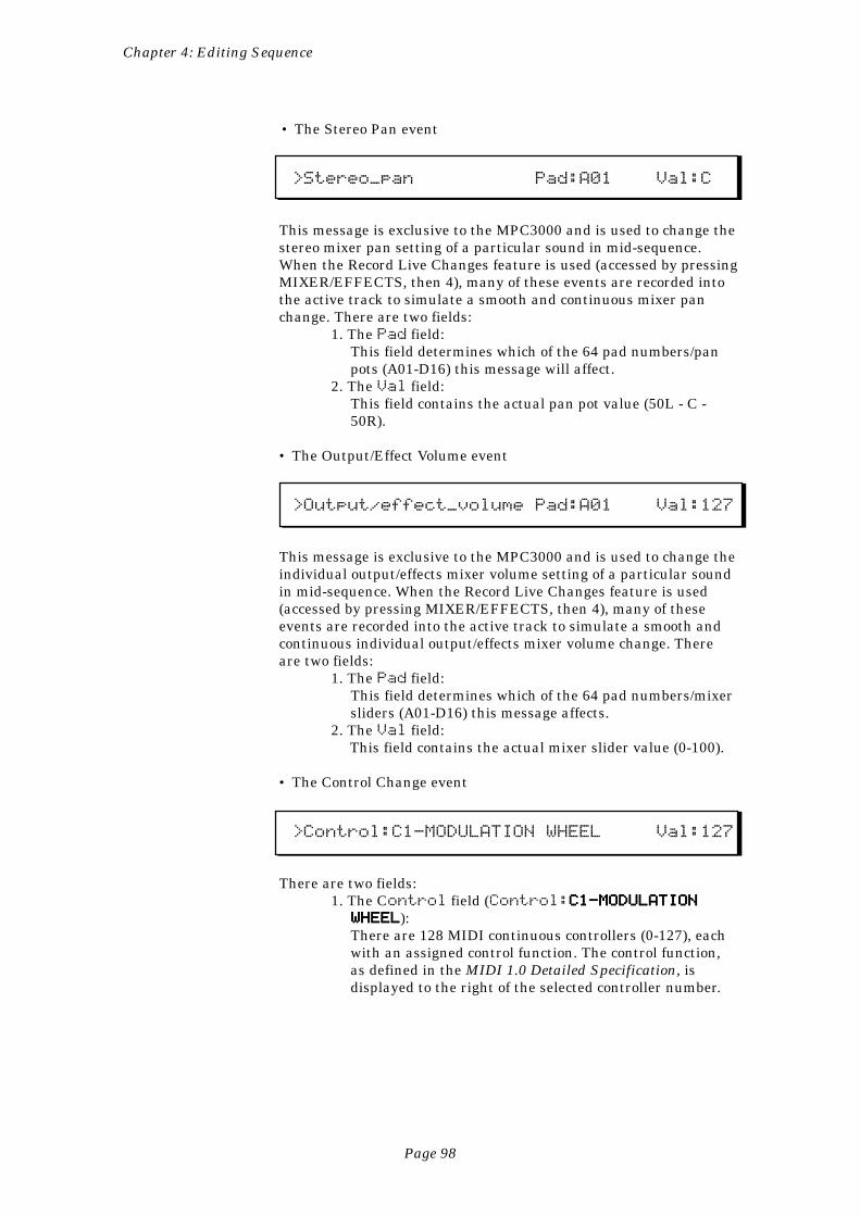
Page 98
Chapter 4: Editing Sequence
• The Stereo Pan event
>Stereo_pan Pad:A01 Val:C
This message is exclusive to the MPC3000 and is used to change thestereo mixer pan setting of a particular sound in mid-sequence.When the Record Live Changes feature is used (accessed by pressingMIXER/EFFECTS, then 4), many of these events are recorded intothe active track to simulate a smooth and continuous mixer panchange. There are two fields:
1. The Pad field:This field determines which of the 64 pad numbers/panpots (A01-D16) this message will affect.
2. The Val field:This field contains the actual pan pot value (50L - C -50R).
• The Output/Effect Volume event
>Output/effect_volume Pad:A01 Val:127
This message is exclusive to the MPC3000 and is used to change theindividual output/effects mixer volume setting of a particular soundin mid-sequence. When the Record Live Changes feature is used(accessed by pressing MIXER/EFFECTS, then 4), many of theseevents are recorded into the active track to simulate a smooth andcontinuous individual output/effects mixer volume change. Thereare two fields:
1. The Pad field:This field determines which of the 64 pad numbers/mixersliders (A01-D16) this message affects.
2. The Val field:This field contains the actual mixer slider value (0-100).
• The Control Change event
>Control:C1-MODULATION WHEEL Val:127
There are two fields:1. The Control field (Control:C1-MODULATIONC1-MODULATIONC1-MODULATIONC1-MODULATIONC1-MODULATION
WHEELWHEELWHEELWHEELWHEEL):There are 128 MIDI continuous controllers (0-127), eachwith an assigned control function. The control function,as defined in the MIDI 1.0 Detailed Specification, isdisplayed to the right of the selected controller number.
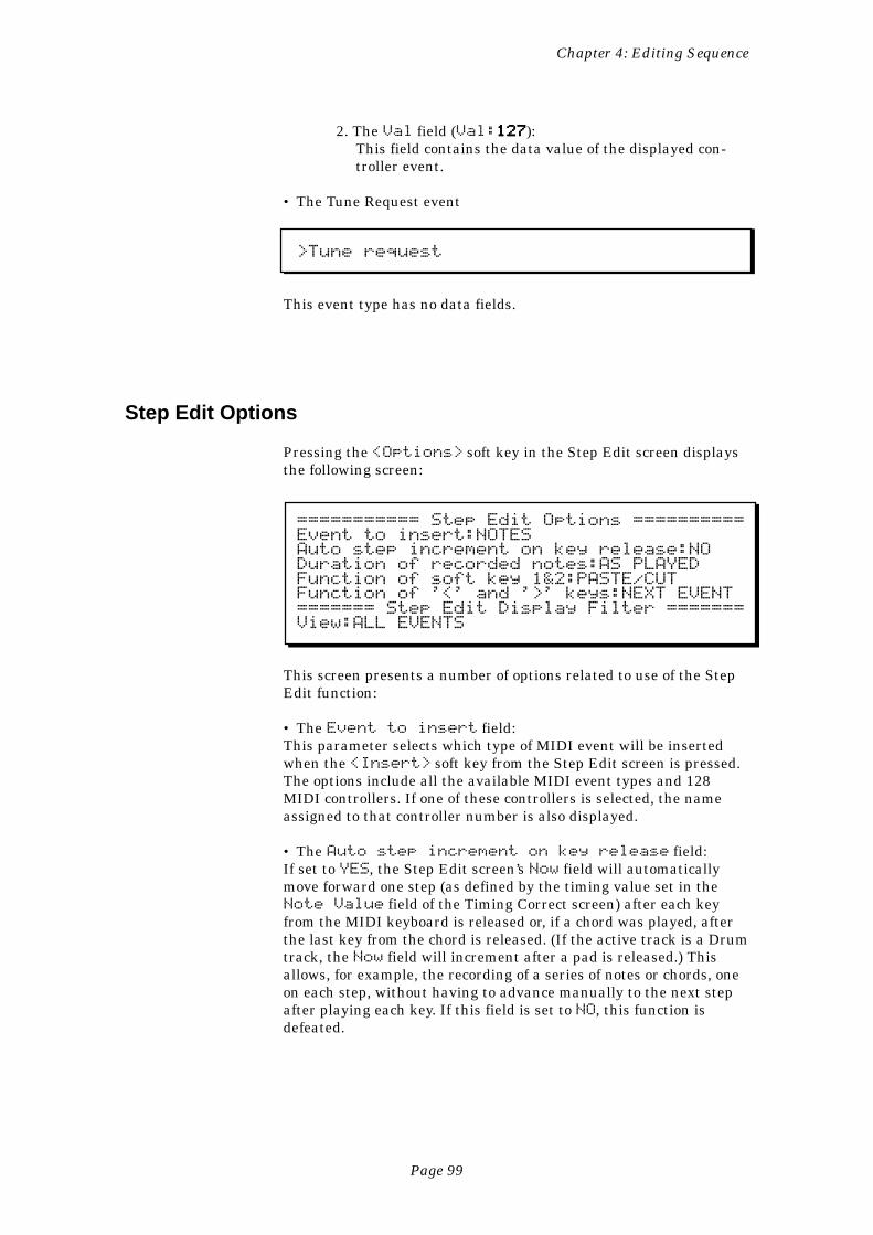
Page 99
Chapter 4: Editing Sequence
2. The Val field (Val:127127127127127):This field contains the data value of the displayed con-troller event.
• The Tune Request event
>Tune request
This event type has no data fields.
Step Edit Options
Pressing the <Options> soft key in the Step Edit screen displaysthe following screen:
=========== Step Edit Options ==========Event to insert:NOTESAuto step increment on key release:NODuration of recorded notes:AS PLAYEDFunction of soft key 1&2:PASTE/CUTFunction of '<' and '>' keys:NEXT EVENT======= Step Edit Display Filter =======View:ALL EVENTS
This screen presents a number of options related to use of the StepEdit function:
• The Event to insert field:This parameter selects which type of MIDI event will be insertedwhen the <Insert> soft key from the Step Edit screen is pressed.The options include all the available MIDI event types and 128MIDI controllers. If one of these controllers is selected, the nameassigned to that controller number is also displayed.
• The Auto step increment on key release field:If set to YES, the Step Edit screen’s Now field will automaticallymove forward one step (as defined by the timing value set in theNote Value field of the Timing Correct screen) after each keyfrom the MIDI keyboard is released or, if a chord was played, afterthe last key from the chord is released. (If the active track is a Drumtrack, the Now field will increment after a pad is released.) Thisallows, for example, the recording of a series of notes or chords, oneon each step, without having to advance manually to the next stepafter playing each key. If this field is set to NO, this function isdefeated.
Page 100
Chapter 4: Editing Sequence
• The Duration of recorded notes field:This field is used while in Step Edit mode to determine the methodby which durations are assigned to notes recorded from a MIDIkeyboard or the MPC3000 pads. This is a choice field and has twooptions: SAME AS STEP and AS PLAYED:
1. If set to SAME AS STEP, durations are always four ticksless than the current step size (the current NoteValue field setting in the Timing Correct screen).
2. If set to AS PLAYED, the actual time the note is held(relative to the current tempo) is used for the durationvalue, even though the sequence is not playing. To guideyour timing, if a key is held down longer than one 1/4-note, a metronome click plays exactly one 1/4-note afterthe key is depressed, and sounds again for each addi-tional 1/4-note the key is held down. For example, if youwanted to record a note with a duration of one 1/2-note,you would play the key and release it after two metro-nome clicks were heard.
• The Function of soft key 1&2 field:This choice field is used to determine the functions of soft keys 1and 2. It has two options:
1. INSERT/DELETE:The functions of soft keys 1 and 2 are <Insert> and<Delete>. <Insert> causes an event to be insertedonto the screen. The type of event is determined by thesetting of the Event to insert field above. <De-lete> removes the active event from the screen.
2. PASTE/CUT.The functions of soft keys 1 and 2 are <Paste> and<Cut>. <Cut> deletes the active event from the screenand saves a copy of it internally. <Paste> inserts ontothe screen a copy of the event most recently cut.
• The Function of '<' And '>' keys field:This choice field is used to determine the function of the REWIND[<] and FAST FORWARD [>] keys. It has two options:
1. NEXT STEP:This is the default setting. Pressing the REWIND [<] keymoves to the previous step within the sequence. Pressingthe FAST FORWARD [>] key moves to the next stepwithin the sequence. (The timing value of a step is set inthe Timing Correct screen’s Note Value field.)
COMMENT: If the current setting of the Swing%field is set to a value other than 50%, pressing theREWIND [<] and FAST FORARD [>] keys willmove forward or backward to locations that fallon swing timing intervals. If you are editing asequence that contains 1/16-notes recorded at aswing setting of 50%, the even-numbered
Page 101
Chapter 4: Editing Sequence
1/16-notes will NOT be heard as you step throughthe sequence, because only notes existing in swung1/16-note locations will be viewed. This same ruleapplies to the Shift Timing function: if the ShiftAmount field is set to 0 and you are editing asequence that was recorded while it was set to anyamount other than 0, none of the notes will be seenas you step through the sequence, because thesenotes fall on shifted locations, and you are cur-rently viewing only those notes that fall on non-shifted locations.
2. NEXT EVENT:Pressing the REWIND [<] key searches to the previousevent within the track. Pressing the FAST FORWARD [>]key searches to the next event within the track. To searchfor specific event types, set the Step Edit Display Filter tothe desired event type; pressing these keys will thencause the MPC3000 to locate to the next or previousevent of the specified type, ignoring event types notincluded in the display filter settings.
• The Step Edit Display Filter section.This is similar to the erase filter or the MIDI input filter, except thisone controls which types of MIDI events are displayed in the StepEdit screen. For example, if the only events you want to edit arepitch bend messages, it is bothersome to view all the other events.Another use is to filter out continuous controller data to make iteasier to view only the note events.
To use the display filter, move the cursor to the View field. This is achoice field with three options:
1. ALL EVENTS: If this option is selected, all possible eventtypes will be displayed.
2. ONLY VIEW: If this option is selected, only one eventtype can be displayed, and the type of event to be dis-played is selected in a new field appearing directly to theright on the same line. In this rightmost field all eventtypes are listed, including all 128 MIDI controllers, eachone individually named as listed in the MIDI 1.0 DetailedSpecification.
3. ALL EXCEPT: This option is similar to ONLY VIEW,detailed above, except that all event types except theevent displayed to the right of the words ALL EXCEPTare displayed.
Page 102
Chapter 4: Editing Sequence
Step Recording
Step Edit also makes it possible to record new notes from a MIDIkeyboard while the sequence is not playing. To record a note whilein Step Edit mode, move to the desired position within the sequence,then play and release the desired note on the MIDI keyboard. Thisnote will then appear as the new active event, with its pitch, veloc-ity, release velocity, and duration displayed numerically. The dura-tion of the note is taken from the actual duration played, relative tothe current tempo. However, if the Duration of recordednotes field in the Step Edit Options screen is set to SAME ASSTEP, The duration always defaults to the current step value.
If the Auto step increment on key release field in theStep Edit Options screen is set to YES, the current position withinthe sequence will automatically advance one step forward when thenewly recorded note (or chord) is released. This allow you to, forexample, record a series of notes (or chords) one at a time whilestopped, and automatically play them back with evenly spacedtiming. To do this:
1. Set up your sequence and track for recording from yourMIDI keyboard as you would to record in real time.
2. In the Timing Correct screen, set the Note value fieldto the desired step value.
3. Rewind to the start of the sequence.4. Press STEP EDIT.5. Press SOFT KEY 4, <Options>.6. Set the Auto step increment on key release
field to YES.7. Press STEP EDIT again.8. Play a series of notes (or chords), one at a time.9. Press PLAY START. The notes you have just entered will
play back with evenly spaced timing.
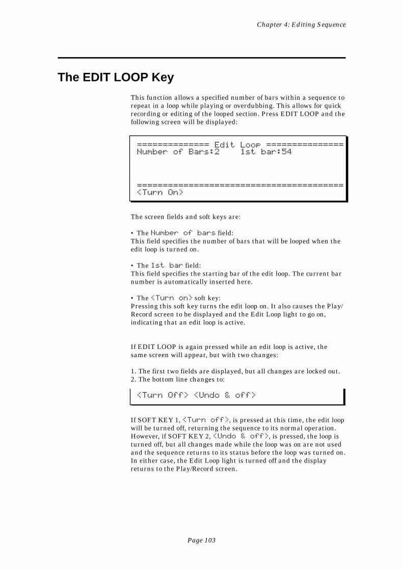
Page 103
Chapter 4: Editing Sequence
The EDIT LOOP Key
This function allows a specified number of bars within a sequence torepeat in a loop while playing or overdubbing. This allows for quickrecording or editing of the looped section. Press EDIT LOOP and thefollowing screen will be displayed:
============== Edit Loop ===============Number of Bars:2 1st bar:54
========================================<Turn On>
The screen fields and soft keys are:
• The Number of bars field:This field specifies the number of bars that will be looped when theedit loop is turned on.
• The 1st bar field:This field specifies the starting bar of the edit loop. The current barnumber is automatically inserted here.
• The <Turn on> soft key:Pressing this soft key turns the edit loop on. It also causes the Play/Record screen to be displayed and the Edit Loop light to go on,indicating that an edit loop is active.
If EDIT LOOP is again pressed while an edit loop is active, thesame screen will appear, but with two changes:
1. The first two fields are displayed, but all changes are locked out.2. The bottom line changes to:
<Turn Off> <Undo & off>
If SOFT KEY 1, <Turn off>, is pressed at this time, the edit loopwill be turned off, returning the sequence to its normal operation.However, if SOFT KEY 2, <Undo & off>, is pressed, the loop isturned off, but all changes made while the loop was on are not usedand the sequence returns to its status before the loop was turned on.In either case, the Edit Loop light is turned off and the displayreturns to the Play/Record screen.
Page 104
Chapter 4: Editing Sequence
Using Edit Loop as an Undo Function
Because the Edit Loop function allows you the option of ignoring allrecording and editing that was done while Edit Loop was on, itserves very well as an undo function.
For example, if you want to record a drum fill on bar 4 of a 4-barsequence, but you aren’t sure if you want to keep it, following thesesteps will allow you to try the fill, then restore the sequence to itsoriginal state if you don’t like it:
1. Fast forward to bar 4.2. Press EDIT LOOP.3. Set the Number of bars field to 1.4. Press SOFT KEY 1, <Turn on>, which will turn the
Edit Loop on. Bar 4 will now repeatedly play in a loop.5. Overdub your drum fill.6. Press EDIT LOOP again.7. If you didn’t like how the fill sounded, press SOFT KEY 2,<Undo & off>, and the sequence will return to itsoriginal state. If you want to keep the fill, press SOFTKEY 1 (<Turn off>) and the sequence will nowcontain the new drum fill.
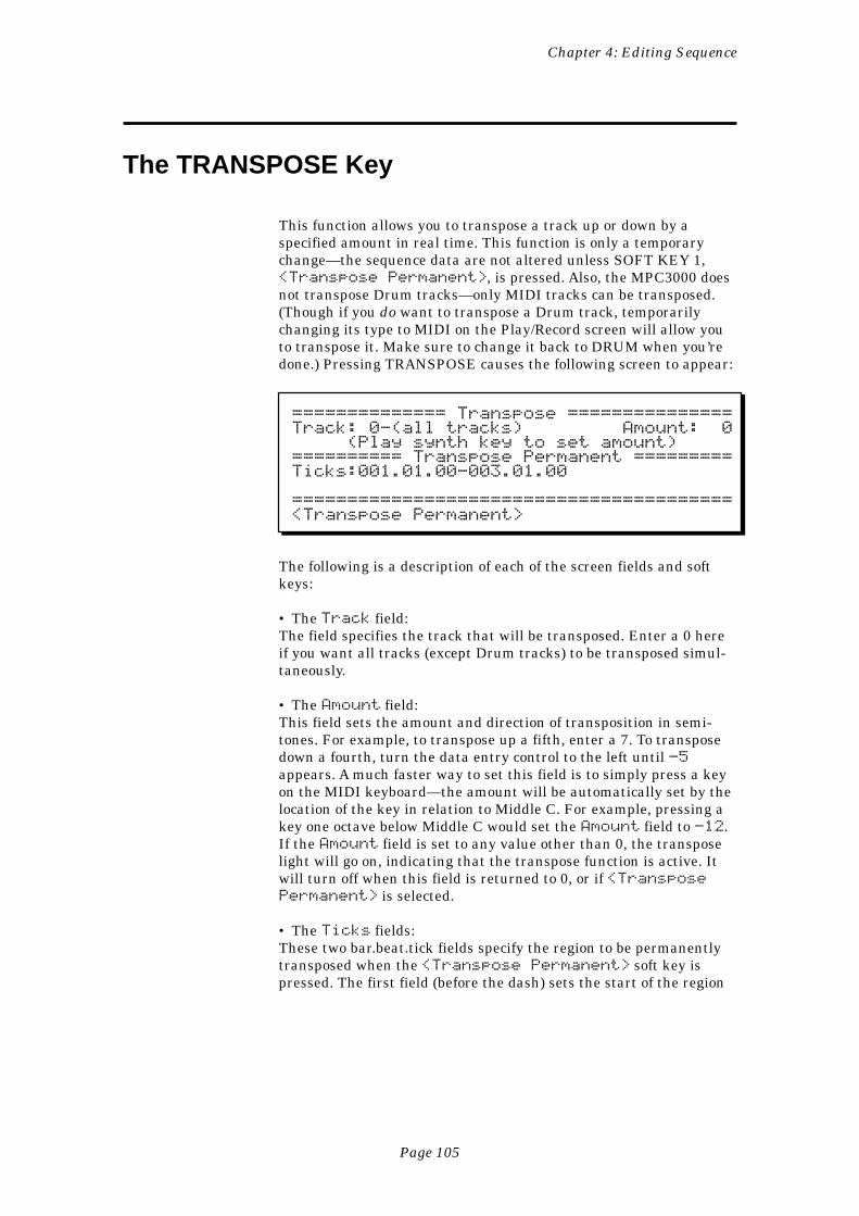
Page 105
Chapter 4: Editing Sequence
The TRANSPOSE Key
This function allows you to transpose a track up or down by aspecified amount in real time. This function is only a temporarychange—the sequence data are not altered unless SOFT KEY 1,<Transpose Permanent>, is pressed. Also, the MPC3000 doesnot transpose Drum tracks—only MIDI tracks can be transposed.(Though if you do want to transpose a Drum track, temporarilychanging its type to MIDI on the Play/Record screen will allow youto transpose it. Make sure to change it back to DRUM when you’redone.) Pressing TRANSPOSE causes the following screen to appear:
============== Transpose ===============Track: 0-(all tracks) Amount: 0 (Play synth key to set amount)========== Transpose Permanent =========Ticks:001.01.00-003.01.00
========================================<Transpose Permanent>
The following is a description of each of the screen fields and softkeys:
• The Track field:The field specifies the track that will be transposed. Enter a 0 hereif you want all tracks (except Drum tracks) to be transposed simul-taneously.
• The Amount field:This field sets the amount and direction of transposition in semi-tones. For example, to transpose up a fifth, enter a 7. To transposedown a fourth, turn the data entry control to the left until -5appears. A much faster way to set this field is to simply press a keyon the MIDI keyboard—the amount will be automatically set by thelocation of the key in relation to Middle C. For example, pressing akey one octave below Middle C would set the Amount field to -12.If the Amount field is set to any value other than 0, the transposelight will go on, indicating that the transpose function is active. Itwill turn off when this field is returned to 0, or if <TransposePermanent> is selected.
• The Ticks fields:These two bar.beat.tick fields specify the region to be permanentlytransposed when the <Transpose Permanent> soft key ispressed. The first field (before the dash) sets the start of the region
Page 106
Chapter 4: Editing Sequence
and the second field sets a location one tick after the last tick of theregion to be transposed.
• The <Transpose Permanent> soft key:Pressing this soft key causes the above-specified transposition to bemade permanent by actually changing each of the note eventswithin the specified region of the sequence. After this operation, theAmount field is reset to 0 and the transpose light goes off.
Transposing in Real Time While Playing
To transpose a sequence in real time while playing, follow thesesteps:
1. Play the sequence.2. Press the TRANSPOSE key.3. Locate Middle C on the keyboard. Pressing any key above Middle
C will instantly transpose the sequence up by an amount equal tothe interval between the new key and Middle C. Pressing any keybelow Middle C will instantly transpose the sequence down by anamount equal to the interval between the new key and Middle C.When you press the transposition key, it will only be used to setthe transposition interval—the note itself will not sound. Be sureto press the key immediately before the instant that you wantthe transposition to occur. To remind you that your sequence isbeing transposed, the light above the TRANSPOSE key will go onif any Amount value other than 0 has been selected.
4. To return to the original key signature, press Middle C or set theAmount field to 0.
Page 107
Chapter 5: Song Mode
Chapter 5:Song Mode
Page 108
Chapter 5: Song Mode
Overview
One way to create a song in the MPC3000 is to record all of theparts in one long sequence, either playing the entire song manuallyor using the copy functions to duplicate repeating sections. Anotherway is use Song mode. In Song mode, several sequences areentered into a list, with each sequence being a different section ofthe whole song. Once the entire list is entered, Song mode automati-cally plays the list of sequences in the order they were entered. Thisis especially useful in creating arrangements that have manyrepeating sections, such as drum parts. Song mode has the followingadvantages over using a long sequence to record a song:
• The song structure can be created very quickly.• The content of the sections of the song can be changed veryquickly.
A song in the MPC3000 consists of up to 250 steps, each of whichcontains the number of the sequence that will play at the step andthe number of times the step will repeat before going on to the nextstep in the song. After the last step, the song can either stop playingor loop back to an earlier step. The MPC3000 can hold up to 20songs in memory at one time. Recording is not permitted in Songmode. Rather, the individual sequences must be recorded or editedwhile in Play/Record mode.
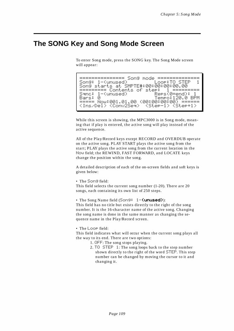
Page 109
Chapter 5: Song Mode
The SONG Key and Song Mode Screen
To enter Song mode, press the SONG key. The Song Mode screenwill appear:
=============== Song mode ==============Song: 1-(unused) Loop:TO STEP 1Song starts at SMPTE#:00:00:00:00.00========= Contents of step: 1 =========Sqnc: 1-(unused) Reps(0=end): 1Bars: 0 Tempo:120.0 BPM===== Now:001.01.00 (00:00:00:00) ======<Ins/Del> <Conv2Seq> <Step-1> <Step+1>
While this screen is showing, the MPC3000 is in Song mode, mean-ing that if play is entered, the active song will play instead of theactive sequence.
All of the Play/Record keys except RECORD and OVERDUB operateon the active song. PLAY START plays the active song from thestart; PLAY plays the active song from the current location in theNow field; the REWIND, FAST FORWARD, and LOCATE keyschange the position within the song.
A detailed description of each of the on-screen fields and soft keys isgiven below:
• The Song field:This field selects the current song number (1-20). There are 20songs, each containing its own list of 250 steps.
• The Song Name field (Song: 1-(unused)(unused)(unused)(unused)(unused)):This field has no title but exists directly to the right of the songnumber. It is the 16-character name of the active song. Changingthe song name is done in the same manner as changing the se-quence name in the Play/Record screen.
• The Loop field:This field indicates what will occur when the current song plays allthe way to its end. There are two options:
1. OFF: The song stops playing.2. TO STEP 1: The song loops back to the step number
shown directly to the right of the word STEP. This stepnumber can be changed by moving the cursor to it andchanging it.
Page 110
Chapter 5: Song Mode
• The SMPTE start field:This five-part field sets the SMPTE number associated with theexact beginning of the song. Also called SMPTE offset, this is theSMPTE number which, when the MPC3000 is syncing to SMPTE,denotes the beginning of the song. Normally, this is set to all zeroes(00:00:00:00.00). The five parts are Hours:Minutes:Seconds:Frames.HundrethFrames.
• The Contents of step field:This shows the current step number (1-250) within the active song.The data displayed below this field are the data contained withinthis step.
• The Sqnc field:This field indicates the sequence number contained in the currentstep. The selected sequence’s name is displayed to the right.
• The Reps(0=end) field:This field indicates the number of repetitions that the sequence inthe current step will play before moving on to the next step. Forexample, if you want the sequence to play only once in the currentstep, a 1 should be entered here. If a 0 is entered here, the MPC3000will treat this step as the end of the song, and either stop playing orloop to a previous step number, depending on the setting of theLoop field.
• The Bars field:This field shows the total number of bars in the selected sequence. Itis for display only and can’t be edited.
• The Tempo field:This field shows the sequence tempo (the tempo value stored withinthe sequence—not the master tempo) of the selected sequence.
• The Now field:This has nearly the same function as in the Play/Record screen,except that in Song mode this number refers to the current positionwithin the song, not within the sequence.
• The <Ins/Del> soft key:This key is used for inserting a new step into a song, deleting a step,or deleting an entire song. Pressing it causes the following screen toappear:
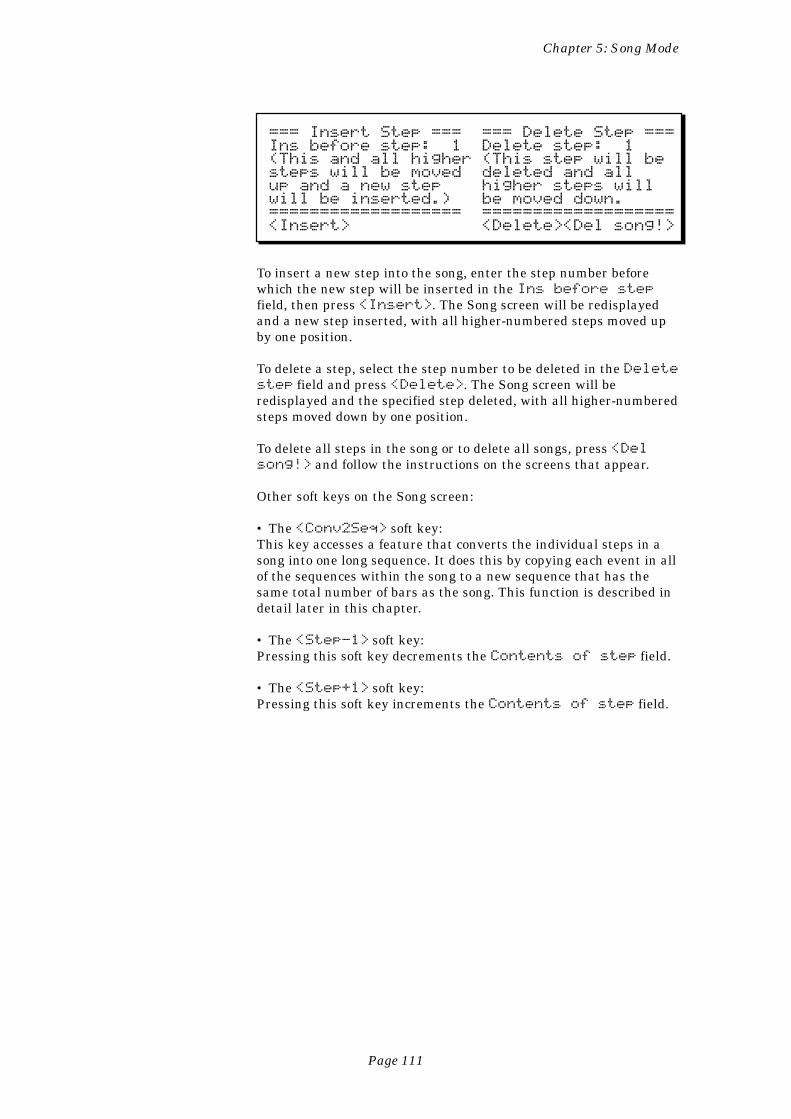
Page 111
Chapter 5: Song Mode
=== Insert Step === === Delete Step ===Ins before step: 1 Delete step: 1(This and all higher (This step will besteps will be moved deleted and allup and a new step higher steps willwill be inserted.) be moved down.=================== ===================<Insert> <Delete><Del song!>
To insert a new step into the song, enter the step number beforewhich the new step will be inserted in the Ins before stepfield, then press <Insert>. The Song screen will be redisplayedand a new step inserted, with all higher-numbered steps moved upby one position.
To delete a step, select the step number to be deleted in the Deletestep field and press <Delete>. The Song screen will beredisplayed and the specified step deleted, with all higher-numberedsteps moved down by one position.
To delete all steps in the song or to delete all songs, press <Delsong!> and follow the instructions on the screens that appear.
Other soft keys on the Song screen:
• The <Conv2Seq> soft key:This key accesses a feature that converts the individual steps in asong into one long sequence. It does this by copying each event in allof the sequences within the song to a new sequence that has thesame total number of bars as the song. This function is described indetail later in this chapter.
• The <Step-1> soft key:Pressing this soft key decrements the Contents of step field.
• The <Step+1> soft key:Pressing this soft key increments the Contents of step field.
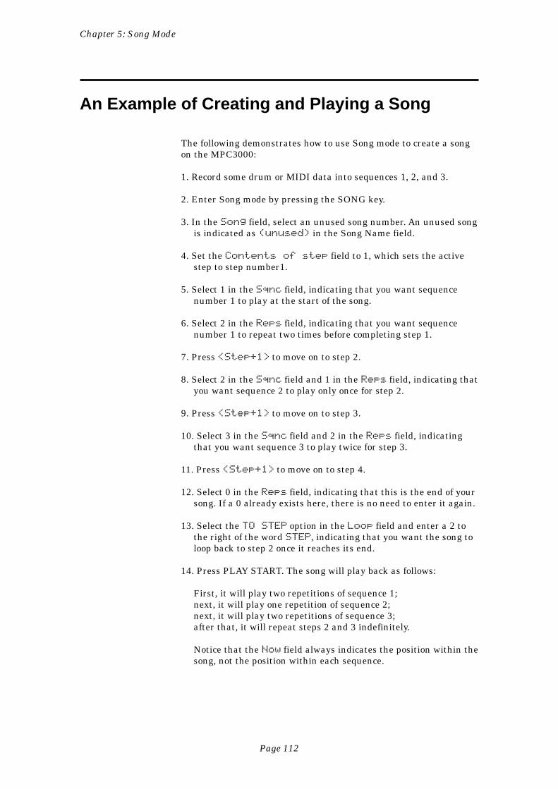
Page 112
Chapter 5: Song Mode
An Example of Creating and Playing a Song
The following demonstrates how to use Song mode to create a songon the MPC3000:
1. Record some drum or MIDI data into sequences 1, 2, and 3.
2. Enter Song mode by pressing the SONG key.
3. In the Song field, select an unused song number. An unused songis indicated as (unused) in the Song Name field.
4. Set the Contents of step field to 1, which sets the activestep to step number1.
5. Select 1 in the Sqnc field, indicating that you want sequencenumber 1 to play at the start of the song.
6. Select 2 in the Reps field, indicating that you want sequencenumber 1 to repeat two times before completing step 1.
7. Press <Step+1> to move on to step 2.
8. Select 2 in the Sqnc field and 1 in the Reps field, indicating thatyou want sequence 2 to play only once for step 2.
9. Press <Step+1> to move on to step 3.
10. Select 3 in the Sqnc field and 2 in the Reps field, indicatingthat you want sequence 3 to play twice for step 3.
11. Press <Step+1> to move on to step 4.
12. Select 0 in the Reps field, indicating that this is the end of yoursong. If a 0 already exists here, there is no need to enter it again.
13. Select the TO STEP option in the Loop field and enter a 2 tothe right of the word STEP, indicating that you want the song toloop back to step 2 once it reaches its end.
14. Press PLAY START. The song will play back as follows:
First, it will play two repetitions of sequence 1;next, it will play one repetition of sequence 2;next, it will play two repetitions of sequence 3;after that, it will repeat steps 2 and 3 indefinitely.
Notice that the Now field always indicates the position within thesong, not the position within each sequence.
Page 113
Chapter 5: Song Mode
COMMENT: Occasionally you may see the message Ana-lyzing sequence. Please wait... on the lowestline of the screen, asking that you wait briefly while theMPC3000 does some thinking. This occurs after you makechanges in the song, but only if the song contains a largenumber of different sequences. Once this process is done, allsubsequent fast-forward, rewind, and locate operations willbe immediate.
COMMENT: If you notice a timing irregularity in your songat the point of transition from one sequence to another, theproblem may be due to the assignments of the Pgm field (inthe Play/Record screen) for the sequence that plays immedi-ately after the timing irregularity. If a sequence containingthese program assignments is played in Song mode (or if thesequence is selected manually while the MPC3000 is play-ing), the sequence’s program assignments are sent out at themoment that the sequence starts to play in the song. This canpresent a problem, because most synthesizers require time tochange programs, which can cause any notes existing at thestart of the new sequence to be delayed. This delay is brief inmost synthesizers, but is usually enough to cause a timingirregularity when it occurs at the start of a sequence. Toavoid this problem, don’t assign program changes to se-quences that you are using in Song mode. If you need to useprogram changes within the song, make sure that no notesexist at the start of the sequences that contain the programchanges. Another alternative is to insert MIDI ProgramChange commands within the sequences in the song atlocations where no notes exist.
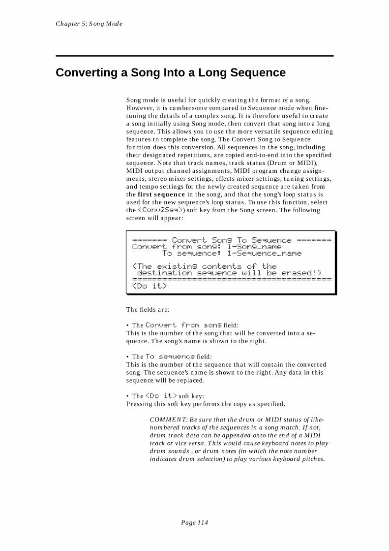
Page 114
Chapter 5: Song Mode
Converting a Song Into a Long Sequence
Song mode is useful for quickly creating the format of a song.However, it is cumbersome compared to Sequence mode when fine-tuning the details of a complex song. It is therefore useful to createa song initially using Song mode, then convert that song into a longsequence. This allows you to use the more versatile sequence editingfeatures to complete the song. The Convert Song to Sequencefunction does this conversion. All sequences in the song, includingtheir designated repetitions, are copied end-to-end into the specifiedsequence. Note that track names, track status (Drum or MIDI),MIDI output channel assignments, MIDI program change assign-ments, stereo mixer settings, effects mixer settings, tuning settings,and tempo settings for the newly created sequence are taken fromthe first sequence in the song, and that the song’s loop status isused for the new sequence’s loop status. To use this function, selectthe <Conv2Seq>) soft key from the Song screen. The followingscreen will appear:
======= Convert Song To Sequence =======Convert from song: 1-Song_name To sequence: 1-Sequence_name
(The existing contents of the destination sequence will be erased!)========================================<Do it>
The fields are:
• The Convert from song field:This is the number of the song that will be converted into a se-quence. The song’s name is shown to the right.
• The To sequence field:This is the number of the sequence that will contain the convertedsong. The sequence’s name is shown to the right. Any data in thissequence will be replaced.
• The <Do it> soft key:Pressing this soft key performs the copy as specified.
COMMENT: Be sure that the drum or MIDI status of like-numbered tracks of the sequences in a song match. If not,drum track data can be appended onto the end of a MIDItrack or vice versa. This would cause keyboard notes to playdrum sounds , or drum notes (in which the note numberindicates drum selection) to play various keyboard pitches.
Page 115
Chapter 6: Creating and Editing Programs
Chapter 6:Creating and
Editing Programs
Page 116
Chapter 6: Creating and Editing Programs
What Are Programs?
A program can be thought of as a drum set. It is a collection of upto 64 sound assignments with accompanying sound modifyingparameters. When a sound is loaded into the MPC3000’s soundmemory, it cannot be played by pads or from MIDI until it is as-signed within a program. In a program, each of 64 legal MIDI notenumbers (35-98) is assigned to one of the 128 possible soundscurrently residing in memory. Once assigned to a note number, asound can be played in one of three ways:
1. By receiving a Note On message from the MIDI input. (The notenumber within the message is used to select which sound toplay.)
2. By playing a front panel drum pad. (Each pad is separatelyassigned to one of 64 MIDI note numbers, 35-98, in the MIDIkey’s option 1 screen.)
3. By playing drum tracks in sequences. (The sound played by asequenced drum note event is determined by its note numberassignment, 35-98.)
In addition to the 64 sound assignments, each program also con-tains a number of sound modifying parameters for each of the 64sound assignments, such as envelope, tuning, filter, mixer, andvelocity response data. Each program also contains some param-eters, such as the settings of the effects generator, that collectivelyaffect all sounds.
The MPC3000 has 24 different programs (of which only one can beactive at a time), each with its own unique set of 64 assignments.Simply by changing the active program number (1-24), all 64 soundassignments and their sound modifying settings will instantlychange. Each program contains the following data:
• Program name• For each of 64 pad numbers (A01-D16):
The note number generated when the pad is played• For each of 64 note numbers (35-98):
Sound assignmentSound assignment mode and related parametersEnvelope attack, decay and decay modeVelocity modulation of volume, attack and start addressTuning, poly assignment and cutoff assignmentsFilter settingsStereo mix volume and panIndividual out/effects mix level“Indiv out/effects level follows stereo volume” (yes/no)
• Note Variation Slider assignment and parameter range limits• Effects settings
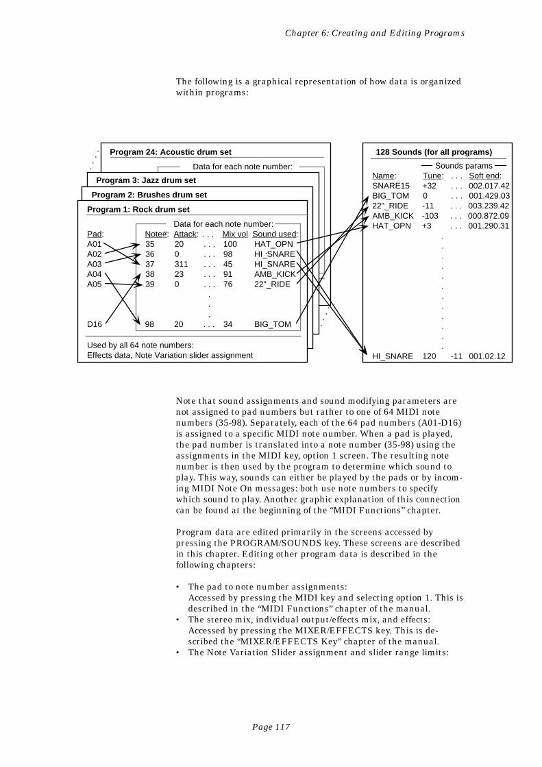
Page 117
Chapter 6: Creating and Editing Programs
The following is a graphical representation of how data is organizedwithin programs:
Data for each note number:Pad: Note#: Attack: . . . Mix vol Sound used:A01 35 20 . . . 100 HAT_OPNA02 36 0 . . . 98 HI_SNAREA03 37 311 . . . 45 HI_SNAREA04 38 23 . . . 91 AMB_KICKA05 39 0 . . . 76 22"_RIDE
. . .
D16 98 20 . . . 34 BIG_TOM
Sounds paramsName: Tune: . . . Soft end:SNARE15 +32 . . . 002.017.42BIG_TOM 0 . . . 001.429.0322"_RIDE -11 . . . 003.239.42AMB_KICK -103 . . . 000.872.09HAT_OPN +3 . . . 001.290.31
.
.
.
.
.
.
.
.
.
.
.
.HI_SNARE 120 -11 001.02.12
Used by all 64 note numbers:Effects data, Note Variation slider assignment
Program 1: Rock drum set
Program 2: Brushes drum set
Program 3: Jazz drum set
Program 24: Acoustic drum set
Data for each note number:
128 Sounds (for all programs)
Note that sound assignments and sound modifying parameters arenot assigned to pad numbers but rather to one of 64 MIDI notenumbers (35-98). Separately, each of the 64 pad numbers (A01-D16)is assigned to a specific MIDI note number. When a pad is played,the pad number is translated into a note number (35-98) using theassignments in the MIDI key, option 1 screen. The resulting notenumber is then used by the program to determine which sound toplay. This way, sounds can either be played by the pads or by incom-ing MIDI Note On messages: both use note numbers to specifywhich sound to play. Another graphic explanation of this connectioncan be found at the beginning of the “MIDI Functions” chapter.
Program data are edited primarily in the screens accessed bypressing the PROGRAM/SOUNDS key. These screens are describedin this chapter. Editing other program data is described in thefollowing chapters:
• The pad to note number assignments:Accessed by pressing the MIDI key and selecting option 1. This isdescribed in the “MIDI Functions” chapter of the manual.
• The stereo mix, individual output/effects mix, and effects:Accessed by pressing the MIXER/EFFECTS key. This is de-scribed the “MIXER/EFFECTS Key” chapter of the manual.
• The Note Variation Slider assignment and slider range limits:
Page 118
Chapter 6: Creating and Editing Programs
Accessed by pressing the Note Variation ASSIGN key. This isdescribed in the “Basics” chapter of the manual.
How to create a program
To create a program, either copy an existing program and modify it,or start a new one:
1. Load in from disk the sounds you intend to use in the program.2. If you want to change the note number assignments for any of the
pads, press the MIDI key and select option 1.3. For each pad you want to assign to a sound, select that pad’s note
number in the “Select Programs, Assign Sounds” screen andassign it to the desired sound and sound assignment mode. Thisscreen is accessed by pressing the PROGRAM/SOUNDS key andselecting option 1.
4. If desired, modify the default settings for envelope, velocitymodulation, tuning, poly mode, cutoff assignments, or filtersettings. These are accessed by selecting options 2 or 3 from thePROGRAM/SOUNDS key menu.
5. If desired, adjust the stereo or individual output/effect mixes oradd effects by pressing the MIXER/EFFECTS key and selectingthe appropriate option.
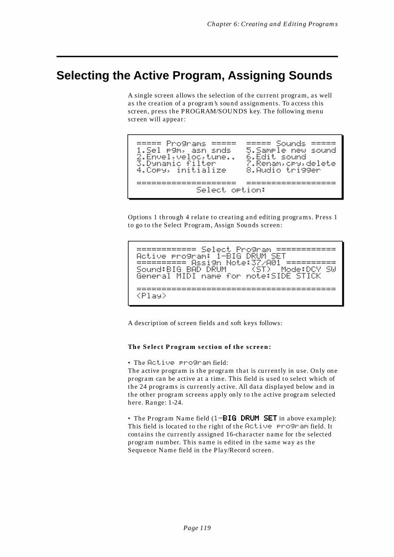
Page 119
Chapter 6: Creating and Editing Programs
Selecting the Active Program, Assigning Sounds
A single screen allows the selection of the current program, as wellas the creation of a program’s sound assignments. To access thisscreen, press the PROGRAM/SOUNDS key. The following menuscreen will appear:
===== Programs ===== ===== Sounds =====1.Sel pgm, asn snds 5.Sample new sound2.Envel,veloc,tune.. 6.Edit sound3.Dynamic filter 7.Renam,cpy,delete4.Copy, initialize 8.Audio trigger
==================== ================== Select option:
Options 1 through 4 relate to creating and editing programs. Press 1to go to the Select Program, Assign Sounds screen:
============ Select Program ============Active program: 1-BIG DRUM SET========== Assign Note:37/A01 ==========Sound:BIG BAD DRUM (ST) Mode:DCY SWGeneral MIDI name for note:SIDE STICK
========================================<Play>
A description of screen fields and soft keys follows:
The Select Program section of the screen:
• The Active program field:The active program is the program that is currently in use. Only oneprogram can be active at a time. This field is used to select which ofthe 24 programs is currently active. All data displayed below and inthe other program screens apply only to the active program selectedhere. Range: 1-24.
• The Program Name field (1-BIG DRUM SETBIG DRUM SETBIG DRUM SETBIG DRUM SETBIG DRUM SET in above example):This field is located to the right of the Active program field. Itcontains the currently assigned 16-character name for the selectedprogram number. This name is edited in the same way as theSequence Name field in the Play/Record screen.
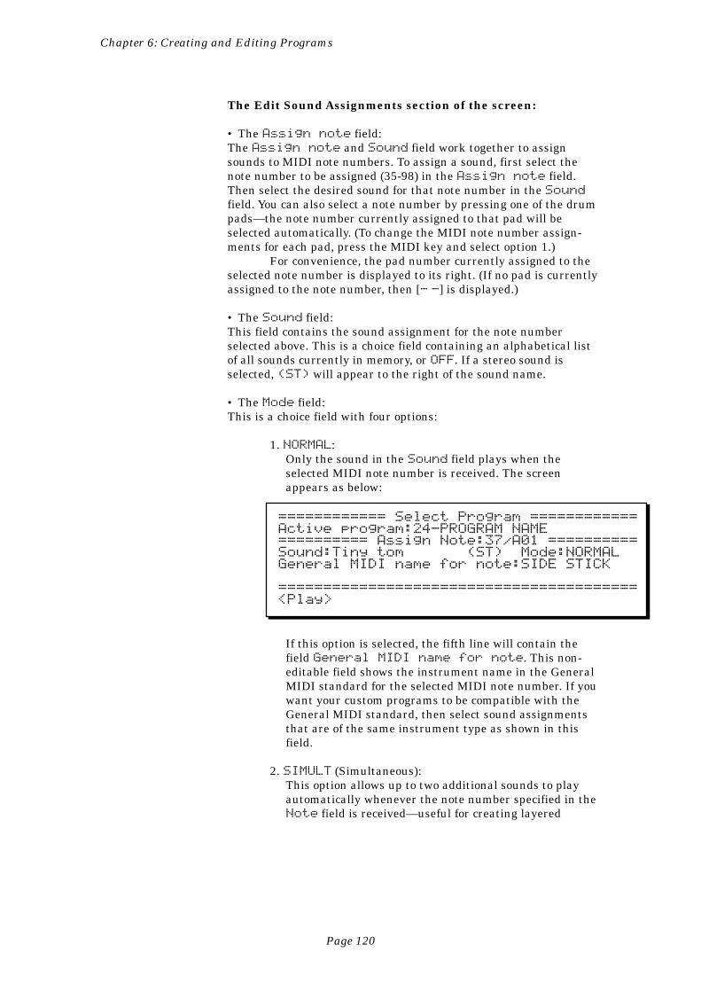
Page 120
Chapter 6: Creating and Editing Programs
The Edit Sound Assignments section of the screen:
• The Assign note field:The Assign note and Sound field work together to assignsounds to MIDI note numbers. To assign a sound, first select thenote number to be assigned (35-98) in the Assign note field.Then select the desired sound for that note number in the Soundfield. You can also select a note number by pressing one of the drumpads—the note number currently assigned to that pad will beselected automatically. (To change the MIDI note number assign-ments for each pad, press the MIDI key and select option 1.)
For convenience, the pad number currently assigned to theselected note number is displayed to its right. (If no pad is currentlyassigned to the note number, then [- -] is displayed.)
• The Sound field:This field contains the sound assignment for the note numberselected above. This is a choice field containing an alphabetical listof all sounds currently in memory, or OFF. If a stereo sound isselected, (ST) will appear to the right of the sound name.
• The Mode field:This is a choice field with four options:
1. NORMAL:Only the sound in the Sound field plays when theselected MIDI note number is received. The screenappears as below:
============ Select Program ============Active program:24-PROGRAM NAME========== Assign Note:37/A01 ==========Sound:Tiny tom (ST) Mode:NORMALGeneral MIDI name for note:SIDE STICK
========================================<Play>
If this option is selected, the fifth line will contain thefield General MIDI name for note. This non-editable field shows the instrument name in the GeneralMIDI standard for the selected MIDI note number. If youwant your custom programs to be compatible with theGeneral MIDI standard, then select sound assignmentsthat are of the same instrument type as shown in thisfield.
2. SIMULT (Simultaneous):This option allows up to two additional sounds to playautomatically whenever the note number specified in theNote field is received—useful for creating layered
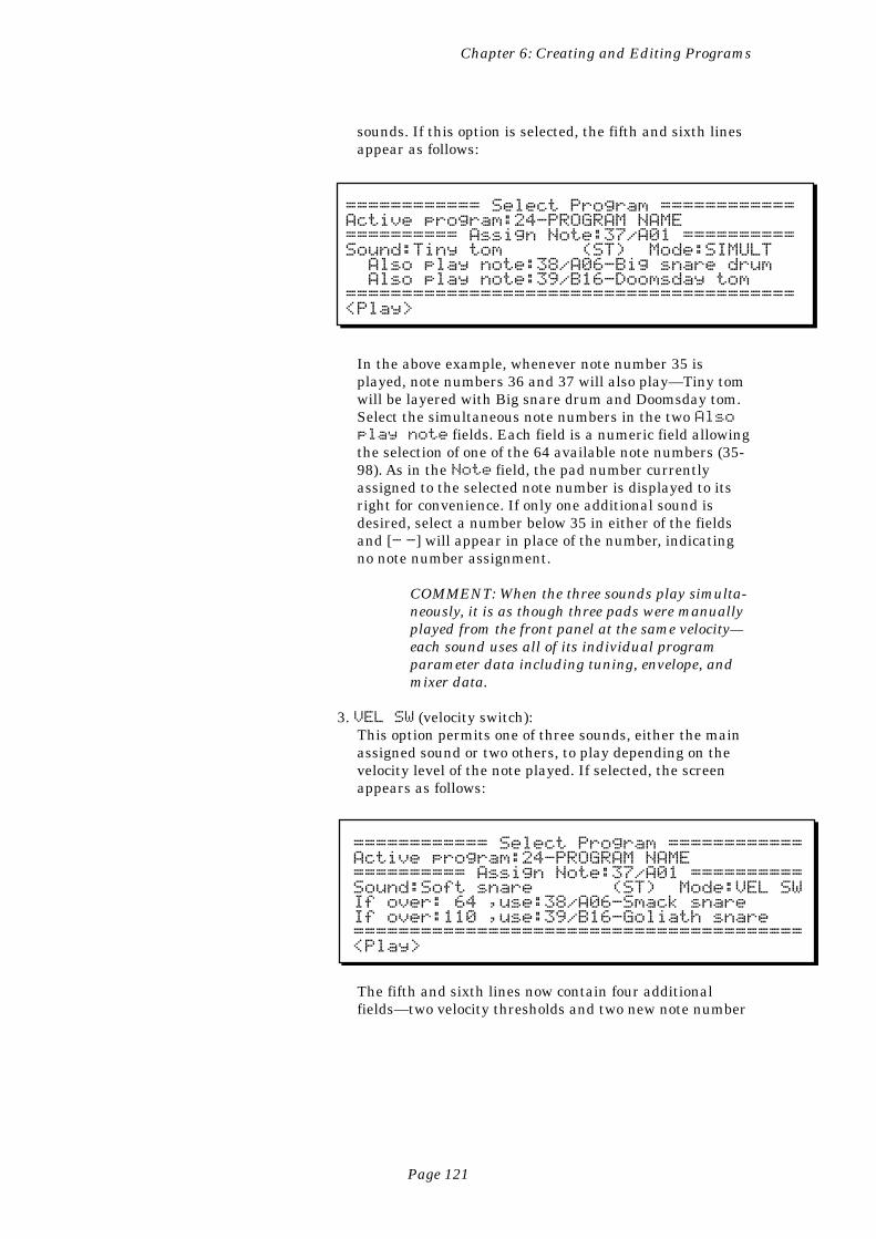
Page 121
Chapter 6: Creating and Editing Programs
sounds. If this option is selected, the fifth and sixth linesappear as follows:
============ Select Program ============Active program:24-PROGRAM NAME========== Assign Note:37/A01 ==========Sound:Tiny tom (ST) Mode:SIMULT Also play note:38/A06-Big snare drum Also play note:39/B16-Doomsday tom========================================<Play>
In the above example, whenever note number 35 isplayed, note numbers 36 and 37 will also play—Tiny tomwill be layered with Big snare drum and Doomsday tom.Select the simultaneous note numbers in the two Alsoplay note fields. Each field is a numeric field allowingthe selection of one of the 64 available note numbers (35-98). As in the Note field, the pad number currentlyassigned to the selected note number is displayed to itsright for convenience. If only one additional sound isdesired, select a number below 35 in either of the fieldsand [- -] will appear in place of the number, indicatingno note number assignment.
COMMENT: When the three sounds play simulta-neously, it is as though three pads were manuallyplayed from the front panel at the same velocity—each sound uses all of its individual programparameter data including tuning, envelope, andmixer data.
3. VEL SW (velocity switch):This option permits one of three sounds, either the mainassigned sound or two others, to play depending on thevelocity level of the note played. If selected, the screenappears as follows:
============ Select Program ============Active program:24-PROGRAM NAME========== Assign Note:37/A01 ==========Sound:Soft snare (ST) Mode:VEL SWIf over: 64 ,use:38/A06-Smack snareIf over:110 ,use:39/B16-Goliath snare========================================<Play>
The fifth and sixth lines now contain four additionalfields—two velocity thresholds and two new note number
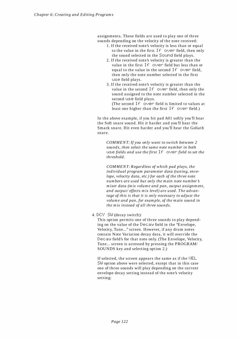
Page 122
Chapter 6: Creating and Editing Programs
assignments. These fields are used to play one of threesounds depending on the velocity of the note received:
1. If the received note’s velocity is less than or equalto the value in the first If over field, then onlythe sound selected in the Sound field plays.
2. If the received note’s velocity is greater than thevalue in the first If over field but less than orequal to the value in the second If over field,then only the note number selected in the firstuse field plays.
3. If the received note’s velocity is greater than thevalue in the second If over field, then only thesound assigned to the note number selected in thesecond use field plays.(The second If over field is limited to values atleast one higher than the first If over field.)
In the above example, if you hit pad A01 softly you’ll hearthe Soft snare sound. Hit it harder and you’ll hear theSmack snare. Hit even harder and you’ll hear the Goliathsnare.
COMMENT: If you only want to switch between 2sounds, then select the same note number in bothuse fields and use the first If over field to set thethreshold.
COMMENT: Regardless of which pad plays, theindividual program parameter data (tuning, enve-lope, velocity data, etc.) for each of the three notenumbers are used but only the main note number’smixer data (mix volume and pan, output assignment,and output/effects mix level) are used. The advan-tage of this is that it is only necessary to adjust thevolume and pan, for example, of the main sound inthe mix instead of all three sounds.
4. DCY SW (decay switch):This option permits one of three sounds to play depend-ing on the value of the Decay field in the “Envelope,Velocity, Tune...” screen. However, if any drum notescontain Note Variation decay data, it will override theDecay field’s for that note only. (The Envelope, Velocity,Tune... screen is accessed by pressing the PROGRAM/SOUNDS key and selecting option 2.)
If selected, the screen appears the same as if the VELSW option above were selected, except that in this caseone of three sounds will play depending on the currentenvelope decay setting instead of the note’s velocitysetting:
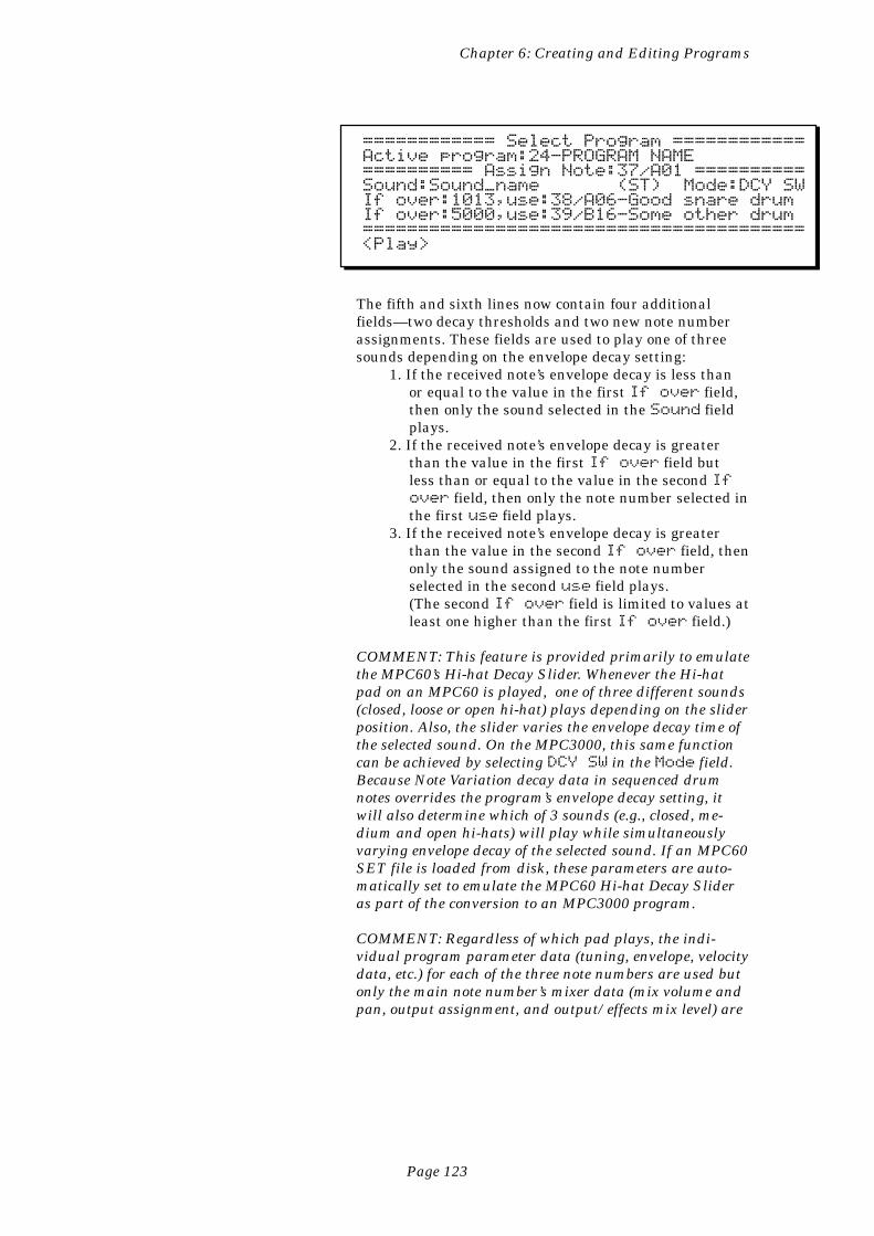
Page 123
Chapter 6: Creating and Editing Programs
============ Select Program ============Active program:24-PROGRAM NAME========== Assign Note:37/A01 ==========Sound:Sound_name (ST) Mode:DCY SWIf over:1013,use:38/A06-Good snare drumIf over:5000,use:39/B16-Some other drum========================================<Play>
The fifth and sixth lines now contain four additionalfields—two decay thresholds and two new note numberassignments. These fields are used to play one of threesounds depending on the envelope decay setting:
1. If the received note’s envelope decay is less thanor equal to the value in the first If over field,then only the sound selected in the Sound fieldplays.
2. If the received note’s envelope decay is greaterthan the value in the first If over field butless than or equal to the value in the second Ifover field, then only the note number selected inthe first use field plays.
3. If the received note’s envelope decay is greaterthan the value in the second If over field, thenonly the sound assigned to the note numberselected in the second use field plays.(The second If over field is limited to values atleast one higher than the first If over field.)
COMMENT: This feature is provided primarily to emulatethe MPC60’s Hi-hat Decay Slider. Whenever the Hi-hatpad on an MPC60 is played, one of three different sounds(closed, loose or open hi-hat) plays depending on the sliderposition. Also, the slider varies the envelope decay time ofthe selected sound. On the MPC3000, this same functioncan be achieved by selecting DCY SW in the Mode field.Because Note Variation decay data in sequenced drumnotes overrides the program’s envelope decay setting, itwill also determine which of 3 sounds (e.g., closed, me-dium and open hi-hats) will play while simultaneouslyvarying envelope decay of the selected sound. If an MPC60SET file is loaded from disk, these parameters are auto-matically set to emulate the MPC60 Hi-hat Decay Slideras part of the conversion to an MPC3000 program.
COMMENT: Regardless of which pad plays, the indi-vidual program parameter data (tuning, envelope, velocitydata, etc.) for each of the three note numbers are used butonly the main note number’s mixer data (mix volume andpan, output assignment, and output/effects mix level) are
Page 124
Chapter 6: Creating and Editing Programs
used. The advantage of this is that it is only necessary toadjust the volume and pan, for example, of the mainsound in the mix instead of all three sounds.
Soft keys:
• The <Play> soft key:Pressing this key has the same effect as playing the selected notenumber at full velocity.
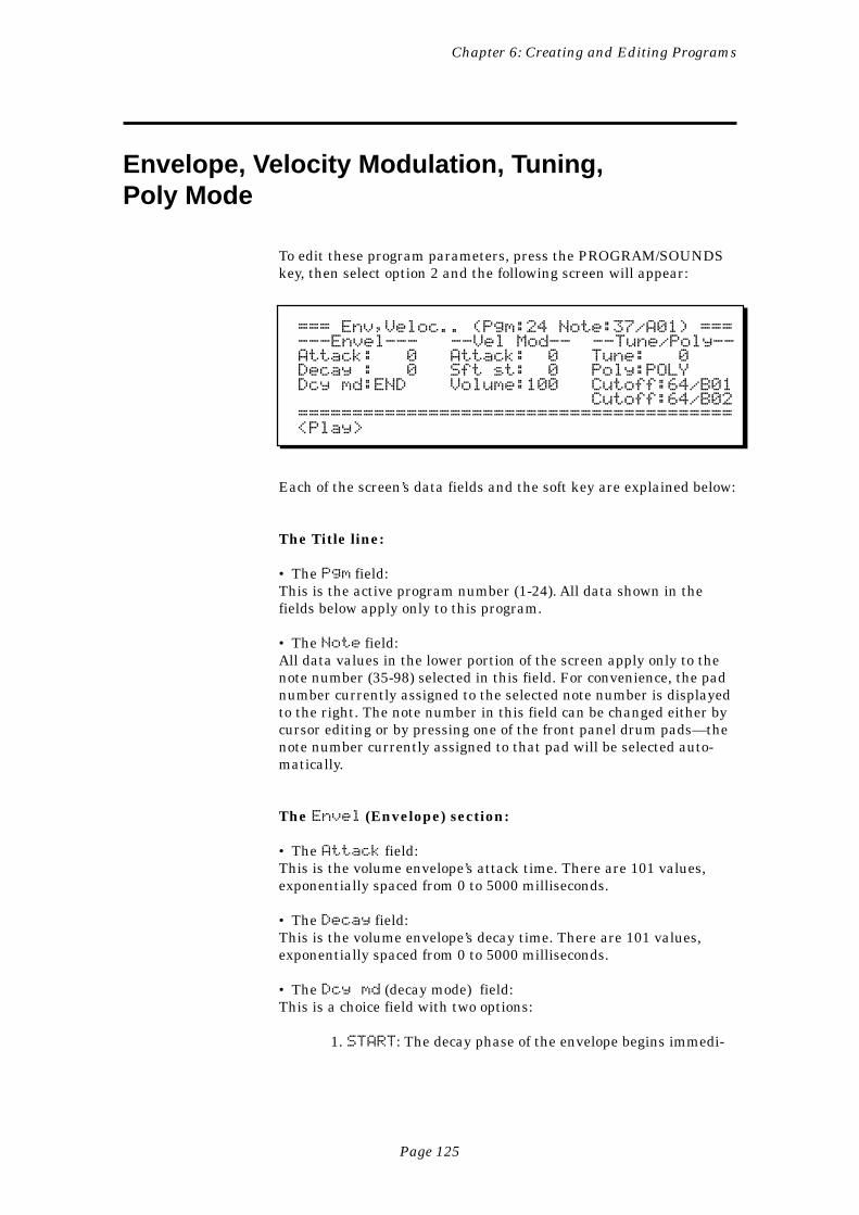
Page 125
Chapter 6: Creating and Editing Programs
Envelope, Velocity Modulation, Tuning,Poly Mode
To edit these program parameters, press the PROGRAM/SOUNDSkey, then select option 2 and the following screen will appear:
=== Env,Veloc.. (Pgm:24 Note:37/A01) ===---Envel--- --Vel Mod-- --Tune/Poly--Attack: 0 Attack: 0 Tune: 0Decay : 0 Sft st: 0 Poly:POLYDcy md:END Volume:100 Cutoff:64/B01 Cutoff:64/B02========================================<Play>
Each of the screen’s data fields and the soft key are explained below:
The Title line:
• The Pgm field:This is the active program number (1-24). All data shown in thefields below apply only to this program.
• The Note field:All data values in the lower portion of the screen apply only to thenote number (35-98) selected in this field. For convenience, the padnumber currently assigned to the selected note number is displayedto the right. The note number in this field can be changed either bycursor editing or by pressing one of the front panel drum pads—thenote number currently assigned to that pad will be selected auto-matically.
The Envel (Envelope) section:
• The Attack field:This is the volume envelope’s attack time. There are 101 values,exponentially spaced from 0 to 5000 milliseconds.
• The Decay field:This is the volume envelope’s decay time. There are 101 values,exponentially spaced from 0 to 5000 milliseconds.
• The Dcy md (decay mode) field:This is a choice field with two options:
1. START: The decay phase of the envelope begins immedi-
Page 126
Chapter 6: Creating and Editing Programs
ately following the attack phase. This is similar to the“envelope initial decay” parameter on most synthesizers.
2. END: The decay phase of the envelope always ends exactlyat the end of the sound playback. The point at which thedecay starts is determined by the decay parameter. Thiswas called fadeout on the MPC60 and is very useful forcreating a smooth fade down just before the end of asampled sound.
The Vel Mod (Velocity Modulation) section:
• The Attack field:This field sets the amount of effect that note velocity has on attacktime (0-100%). If set to 0, note velocity has no effect on attack; if setto higher values, attack time will increase as you play lower veloci-ties. That is, hitting a pad hard will produce a faster attack thanhitting it softly.
• The Sft st (soft start) field:This field controls the amount of time (0-5000 ms) that will be addedto the sound’s Soft Start location when notes with low velocities arereceived. (The Soft Start field is located in the screen accessed bypressing the PROGRAM/SOUNDS key and selecting option 6 fromthe menu.) This provides a good simulation of the way a real drumsounds differently when hit softly. If you set this field above 0,hitting a pad more softly will start playback later in the sample,causing fewer attack transients to be heard. Notes with velocity = 1will add the full amount of time entered here to the Soft Startlocation; notes with velocity = 127 will add nothing; notes withvelocities in between will add time proportionately. If this field is setto 0, note velocity will have no effect on the Soft Start location.
• The Volume field:This field sets the amount of effect that note velocity has on volume(0-100%). If set to 0, note velocity has no effect on volume; if set tohigher values, the volume will decrease as you play lower velocities.
The Tune/Poly section:
• The Tune field:This sets the tuning. The range is from -240 (-24 semitones) to 240(+24 semitones) in increments of 0.1 semitone.
• The Poly field:This is a choice field with three options:
1.POLY: Multiple plays of the sound are assigned to addi-tional voices, allowing polyphonic overlap. This is usefulfor sounds like ride cymbals, for which you don’t wantnew notes to cut off old ones.
Page 127
Chapter 6: Creating and Editing Programs
2. MONO: Multiple plays of the sound use the same voice,terminating and restarting playback of the sound (nopolyphonic overlap). This is useful for producing stutter-ing effects.
3. NOTE OFF: When the pad is released (or a MIDI NoteOff message is received), the sound is terminated. This isuseful for controlling long samples.
• The two Cutoff fields:Each of these two fields allows a note number to be entered. When-ever the note selected in the top line’s Note field is played, thenany currently playing sounds assigned to either of the note numbersin these two fields are immediately terminated.
This is useful when it is desirable for one sound to causeanother to stop playing, such as a closed hi-hat stopping an open hi-hat, or a muted triangle stopping an open triangle.
Each of these two fields allows a note number to be entered(35-98). In each case, the pad currently assigned to that note num-ber is displayed to its right. To disable this feature in either or bothfields, enter a note lower than 35 and “--/OFF” will appear in thefield indicating that no note is selected to be cut off.
The soft key:
• The <Play > soft key:Pressing this key has the same effect as playing the selected notenumber at full velocity.
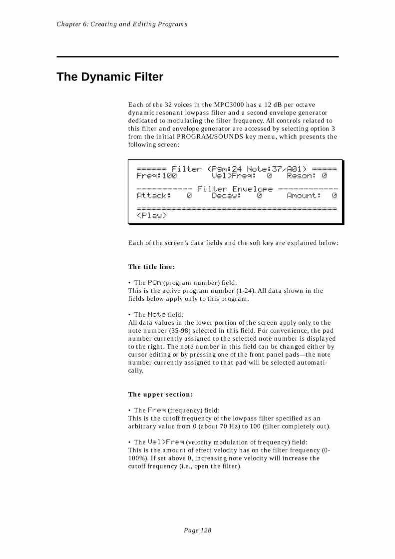
Page 128
Chapter 6: Creating and Editing Programs
The Dynamic Filter
Each of the 32 voices in the MPC3000 has a 12 dB per octavedynamic resonant lowpass filter and a second envelope generatordedicated to modulating the filter frequency. All controls related tothis filter and envelope generator are accessed by selecting option 3from the initial PROGRAM/SOUNDS key menu, which presents thefollowing screen:
====== Filter (Pgm:24 Note:37/A01) =====Freq:100 Vel>Freq: 0 Reson: 0
----------- Filter Envelope ------------Attack: 0 Decay: 0 Amount: 0
========================================<Play>
Each of the screen’s data fields and the soft key are explained below:
The title line:
• The Pgm (program number) field:This is the active program number (1-24). All data shown in thefields below apply only to this program.
• The Note field:All data values in the lower portion of the screen apply only to thenote number (35-98) selected in this field. For convenience, the padnumber currently assigned to the selected note number is displayedto the right. The note number in this field can be changed either bycursor editing or by pressing one of the front panel pads—the notenumber currently assigned to that pad will be selected automati-cally.
The upper section:
• The Freq (frequency) field:This is the cutoff frequency of the lowpass filter specified as anarbitrary value from 0 (about 70 Hz) to 100 (filter completely out).
• The Vel>Freq (velocity modulation of frequency) field:This is the amount of effect velocity has on the filter frequency (0-100%). If set above 0, increasing note velocity will increase thecutoff frequency (i.e., open the filter).
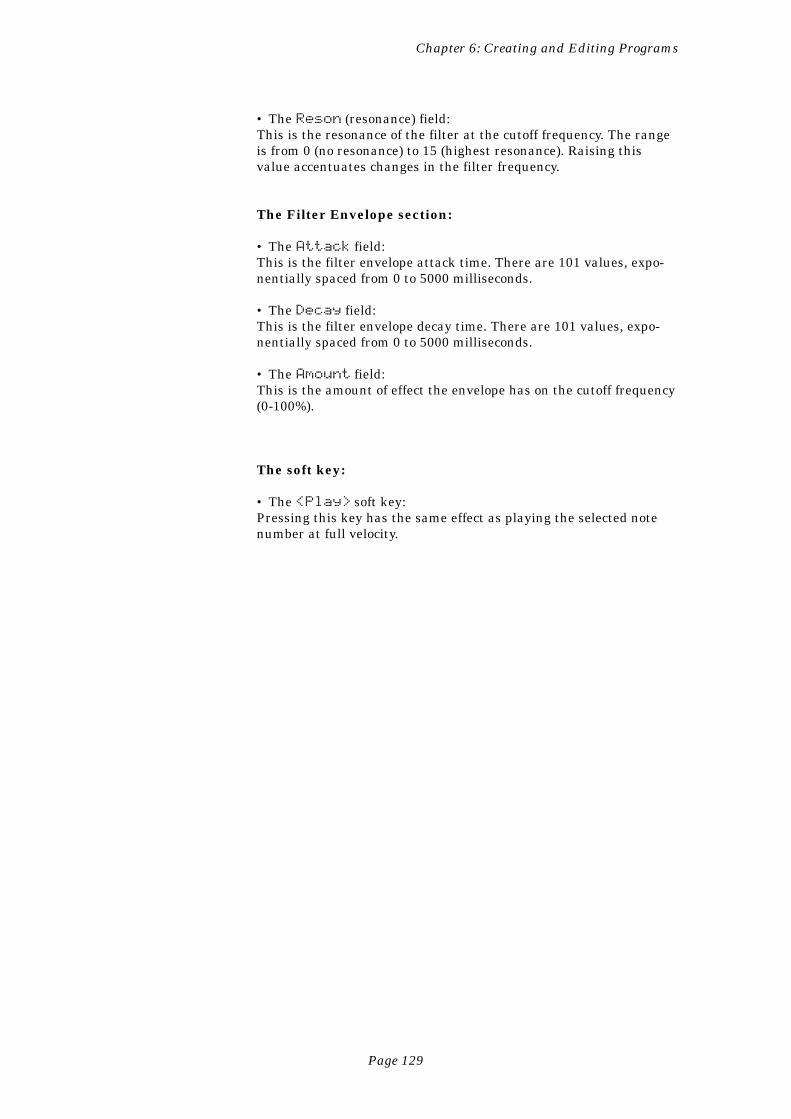
Page 129
Chapter 6: Creating and Editing Programs
• The Reson (resonance) field:This is the resonance of the filter at the cutoff frequency. The rangeis from 0 (no resonance) to 15 (highest resonance). Raising thisvalue accentuates changes in the filter frequency.
The Filter Envelope section:
• The Attack field:This is the filter envelope attack time. There are 101 values, expo-nentially spaced from 0 to 5000 milliseconds.
• The Decay field:This is the filter envelope decay time. There are 101 values, expo-nentially spaced from 0 to 5000 milliseconds.
• The Amount field:This is the amount of effect the envelope has on the cutoff frequency(0-100%).
The soft key:
• The <Play> soft key:Pressing this key has the same effect as playing the selected notenumber at full velocity.
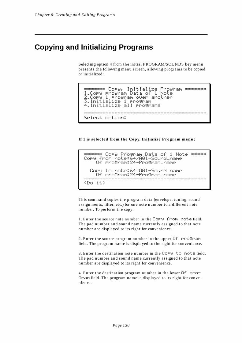
Page 130
Chapter 6: Creating and Editing Programs
Copying and Initializing Programs
Selecting option 4 from the initial PROGRAM/SOUNDS key menupresents the following menu screen, allowing programs to be copiedor initialized:
======= Copy, Initialize Program =======1.Copy program Data of 1 Note2.Copy 1 program over another3.Initialize 1 program4.Initialize all programs
========================================Select option:
If 1 is selected from the Copy, Initialize Program menu:
====== Copy Program Data of 1 Note =====Copy from note:64/A01-Sound_name Of program:24-Program_name
Copy to note:64/A01-Sound_name Of program:24-Program_name========================================<Do it>
This command copies the program data (envelope, tuning, soundassignments, filter, etc.) for one note number to a different notenumber. To perform the copy:
1. Enter the source note number in the Copy from note field.The pad number and sound name currently assigned to that notenumber are displayed to its right for convenience.
2. Enter the source program number in the upper Of programfield. The program name is displayed to the right for convenience.
3. Enter the destination note number in the Copy to note field.The pad number and sound name currently assigned to that notenumber are displayed to its right for convenience.
4. Enter the destination program number in the lower Of pro-gram field. The program name is displayed to its right for conve-nience.
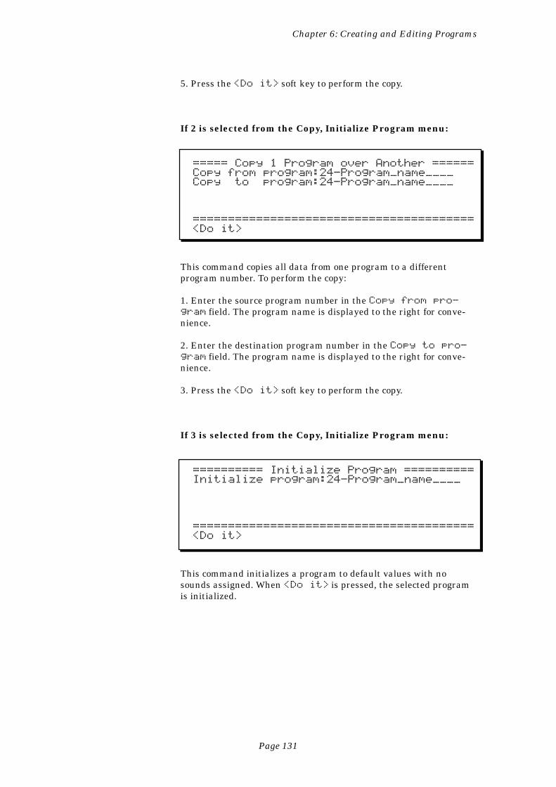
Page 131
Chapter 6: Creating and Editing Programs
5. Press the <Do it> soft key to perform the copy.
If 2 is selected from the Copy, Initialize Program menu:
===== Copy 1 Program over Another ======Copy from program:24-Program_name____Copy to program:24-Program_name____
========================================<Do it>
This command copies all data from one program to a differentprogram number. To perform the copy:
1. Enter the source program number in the Copy from pro-gram field. The program name is displayed to the right for conve-nience.
2. Enter the destination program number in the Copy to pro-gram field. The program name is displayed to the right for conve-nience.
3. Press the <Do it> soft key to perform the copy.
If 3 is selected from the Copy, Initialize Program menu:
========== Initialize Program ==========Initialize program:24-Program_name____
========================================<Do it>
This command initializes a program to default values with nosounds assigned. When <Do it> is pressed, the selected programis initialized.
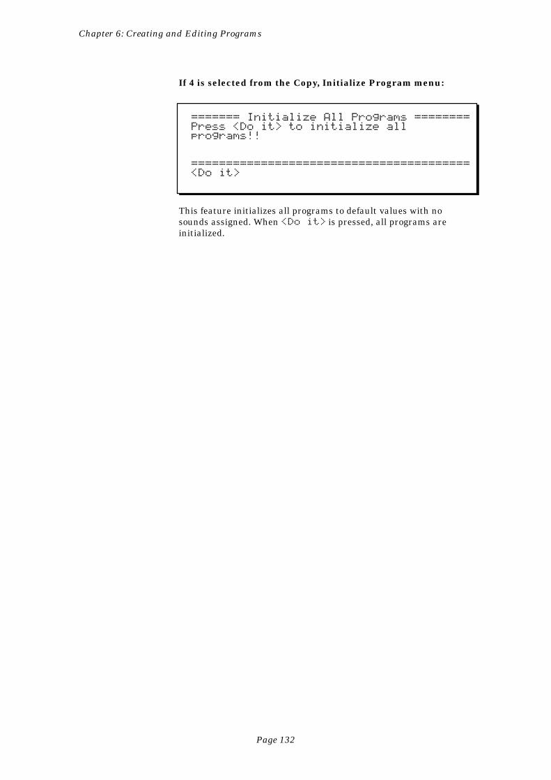
Page 132
Chapter 6: Creating and Editing Programs
If 4 is selected from the Copy, Initialize Program menu:
======= Initialize All Programs ========Press <Do it> to initialize allprograms!!
========================================<Do it>
This feature initializes all programs to default values with nosounds assigned. When <Do it> is pressed, all programs areinitialized.
Page 133
Chapter 7: The MIXER/EFFECTS Key
Chapter 7:The
MIXER/EFFECTSKey
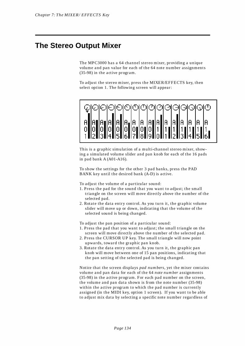
Page 134
Chapter 7: The MIXER/EFFECTS Key
The Stereo Output Mixer
The MPC3000 has a 64 channel stereo mixer, providing a uniquevolume and pan value for each of the 64 note number assignments(35-98) in the active program.
To adjust the stereo mixer, press the MIXER/EFFECTS key, thenselect option 1. The following screen will appear:
This is a graphic simulation of a multi-channel stereo mixer, show-ing a simulated volume slider and pan knob for each of the 16 padsin pad bank A (A01-A16).
To show the settings for the other 3 pad banks, press the PADBANK key until the desired bank (A-D) is active.
To adjust the volume of a particular sound:1. Press the pad for the sound that you want to adjust; the small
triangle on the screen will move directly above the number of theselected pad.
2. Rotate the data entry control. As you turn it, the graphic volumeslider will move up or down, indicating that the volume of theselected sound is being changed.
To adjust the pan position of a particular sound:1. Press the pad that you want to adjust; the small triangle on the
screen will move directly above the number of the selected pad.2. Press the CURSOR UP key. The small triangle will now point
upwards, toward the graphic pan knob.3. Rotate the data entry control. As you turn it, the graphic pan
knob will move between one of 15 pan positions, indicating thatthe pan setting of the selected pad is being changed.
Notice that the screen displays pad numbers, yet the mixer containsvolume and pan data for each of the 64 note number assignments(35-98) in the active program. For each pad number on the screen,the volume and pan data shown is from the note number (35-98)within the active program to which the pad number is currentlyassigned (in the MIDI key, option 1 screen). If you want to be ableto adjust mix data by selecting a specific note number regardless of
Page 135
Chapter 7: The MIXER/EFFECTS Key
its pad assignment, use the All Mix Data (Text) function, accessedby selecting option 3 from the initial MIXER/EFFECTS key menu.
COMMENT: The data values used for the volume and pandisplays are normally taken from the active program. Be-cause of this, whenever the active program is changed, thenewly selected program’s stereo mix settings will immediatelybecome active. However, it is also possible to use mix datafrom the active sequence so that each newly selected sequencewill have its own custom mix, or to use a single master set ofmix data so that the stereo mix never changes when either theprogram or sequence is changed. This choice may be made inthe Mixer Source Select fields, accessed by pressing option 4from the MIXER/EFFECTS key menu.
• SOFT KEY 1:Even though no soft key functions are displayed on the screen, thereis one active soft key: pressing SOFT KEY 1 will change the mixerto a mode in which all pads are edited simultaneously, indicated by16 cursor triangles across the screen. Thus, you can fade or pan allpads in a bank at the same time. You can toggle between volumeand pan control with the UP and DOWN cursor keys. To return tonormal operation, press SOFT KEY 1 again.
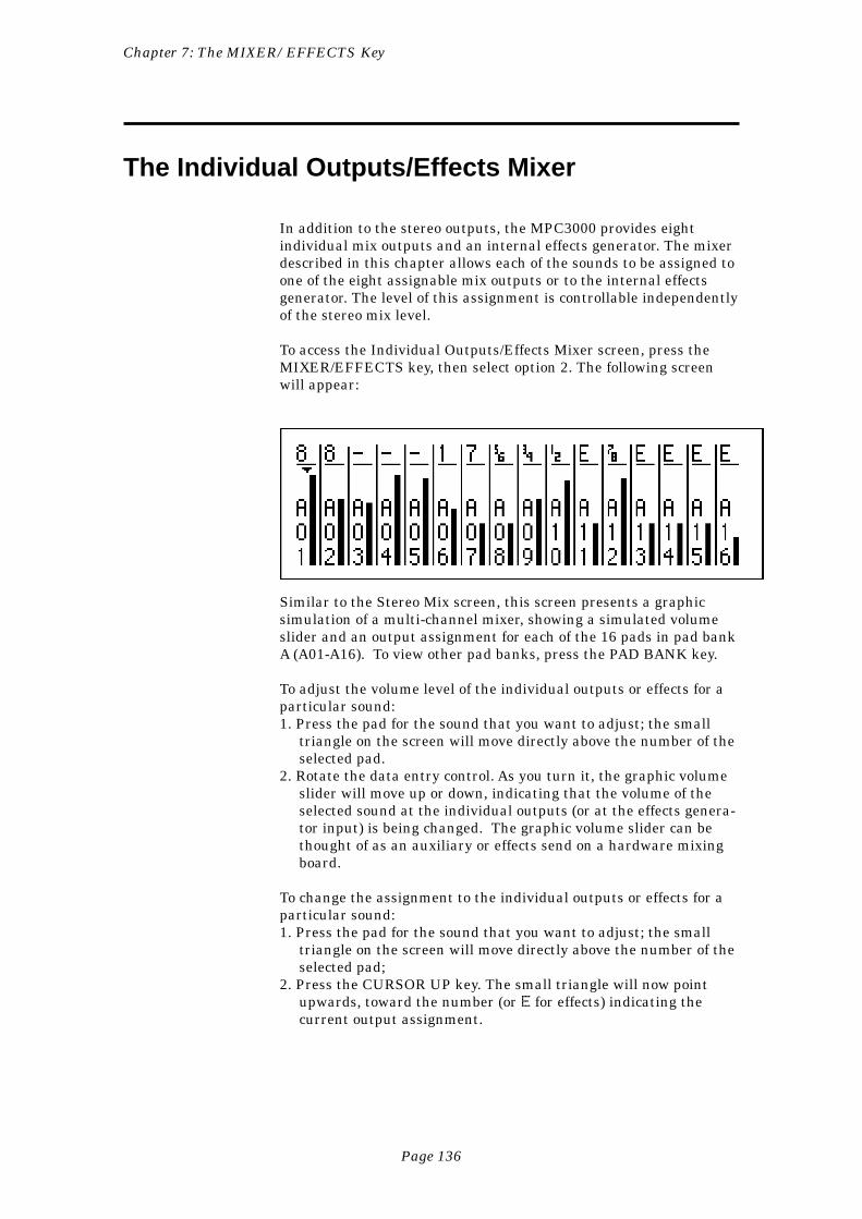
Page 136
Chapter 7: The MIXER/EFFECTS Key
The Individual Outputs/Effects Mixer
In addition to the stereo outputs, the MPC3000 provides eightindividual mix outputs and an internal effects generator. The mixerdescribed in this chapter allows each of the sounds to be assigned toone of the eight assignable mix outputs or to the internal effectsgenerator. The level of this assignment is controllable independentlyof the stereo mix level.
To access the Individual Outputs/Effects Mixer screen, press theMIXER/EFFECTS key, then select option 2. The following screenwill appear:
Similar to the Stereo Mix screen, this screen presents a graphicsimulation of a multi-channel mixer, showing a simulated volumeslider and an output assignment for each of the 16 pads in pad bankA (A01-A16). To view other pad banks, press the PAD BANK key.
To adjust the volume level of the individual outputs or effects for aparticular sound:1. Press the pad for the sound that you want to adjust; the small
triangle on the screen will move directly above the number of theselected pad.
2. Rotate the data entry control. As you turn it, the graphic volumeslider will move up or down, indicating that the volume of theselected sound at the individual outputs (or at the effects genera-tor input) is being changed. The graphic volume slider can bethought of as an auxiliary or effects send on a hardware mixingboard.
To change the assignment to the individual outputs or effects for aparticular sound:1. Press the pad for the sound that you want to adjust; the small
triangle on the screen will move directly above the number of theselected pad;
2. Press the CURSOR UP key. The small triangle will now pointupwards, toward the number (or E for effects) indicating thecurrent output assignment.

Page 137
Chapter 7: The MIXER/EFFECTS Key
3. Rotate the data entry control. Turning it will rotate through tenselections:
[-] The pad’s sound has no output assignment1 The pad’s sound is sent to individual output 12 The pad’s sound is sent to individual output 23 The pad’s sound is sent to individual output 34 The pad’s sound is sent to individual output 45 The pad’s sound is sent to individual output 56 The pad’s sound is sent to individual output 67 The pad’s sound is sent to individual output 78 The pad’s sound is sent to individual output 8E The pad’s sound is sent to the internal effects
generatorIf the sound being adjusted is a stereo sound, then the availableselections are different:
[-] The pad’s sound has no output assignment[ ] The left side of the sound is sent to individual output
1 and the right side is sent to individual output 2[ ] The left side of the sound is sent to individual output
3 and the right side is sent to individual output 4[ ] The left side of the sound is sent to individual output
5 and the right side is sent to individual output 6[ ] The left side of the sound is sent to individual output
7 and the right side is sent to individual output 8[E] Both sides of the sound are sent to the internal
effects generator
Notice that the screen displays pad numbers, yet the mixer containsdata for each of the 64 note number assignments (35-98) in theactive program. For each pad number on the screen, the data shownis from the note number (35-98) within the active program to whichthe pad number is currently assigned (in the MIDI key, option 1screen). If you want to be able to adjust mix data by selecting aspecific note number regardless of its pad assignment, use the AllMix Data (Text) function, accessed by selecting option 3 from theinitial MIXER/EFFECTS key menu.
COMMENT: The data values used for this mixer are nor-mally taken from the active program. Because of this, when-ever the active program is changed, the newly selectedprogram’s individual output assign and mix settings willimmediately become active. However, it is also possible to usesettings from the active sequence so that each newly selectedsequence will have its own custom settings, or to use a singlemaster set of individual out assignments and mix data sothat the settings never change when either the program orsequence is changed. This choice may be made in the MixerSource Select fields, accessed by pressing option 4 from theMIXER/EFFECTS key menu.
Page 138
Chapter 7: The MIXER/EFFECTS Key
• SOFT KEY 1:Even though no soft key functions are displayed on the screen, thereis one active soft key: If SOFT KEY 1 is pressed while the triangularcursor is pointing downward???, the mixer changes to a mode inwhich all sliders or output assignments are moved simultaneously,indicated by 16 cursor triangles across the screen. To return tonormal operation, press SOFT KEY 1 again.
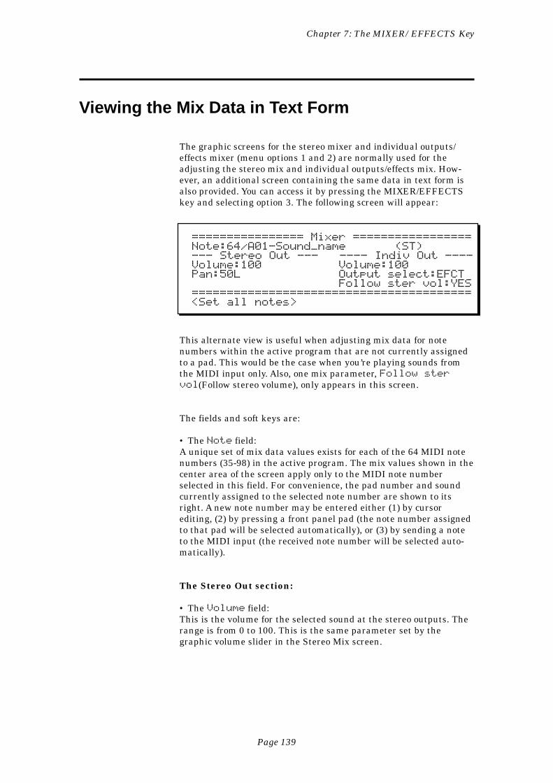
Page 139
Chapter 7: The MIXER/EFFECTS Key
Viewing the Mix Data in Text Form
The graphic screens for the stereo mixer and individual outputs/effects mixer (menu options 1 and 2) are normally used for theadjusting the stereo mix and individual outputs/effects mix. How-ever, an additional screen containing the same data in text form isalso provided. You can access it by pressing the MIXER/EFFECTSkey and selecting option 3. The following screen will appear:
================ Mixer =================Note:64/A01-Sound_name (ST)--- Stereo Out --- ---- Indiv Out ----Volume:100 Volume:100Pan:50L Output select:EFCT Follow ster vol:YES========================================<Set all notes>
This alternate view is useful when adjusting mix data for notenumbers within the active program that are not currently assignedto a pad. This would be the case when you’re playing sounds fromthe MIDI input only. Also, one mix parameter, Follow stervol(Follow stereo volume), only appears in this screen.
The fields and soft keys are:
• The Note field:A unique set of mix data values exists for each of the 64 MIDI notenumbers (35-98) in the active program. The mix values shown in thecenter area of the screen apply only to the MIDI note numberselected in this field. For convenience, the pad number and soundcurrently assigned to the selected note number are shown to itsright. A new note number may be entered either (1) by cursorediting, (2) by pressing a front panel pad (the note number assignedto that pad will be selected automatically), or (3) by sending a noteto the MIDI input (the received note number will be selected auto-matically).
The Stereo Out section:
• The Volume field:This is the volume for the selected sound at the stereo outputs. Therange is from 0 to 100. This is the same parameter set by thegraphic volume slider in the Stereo Mix screen.
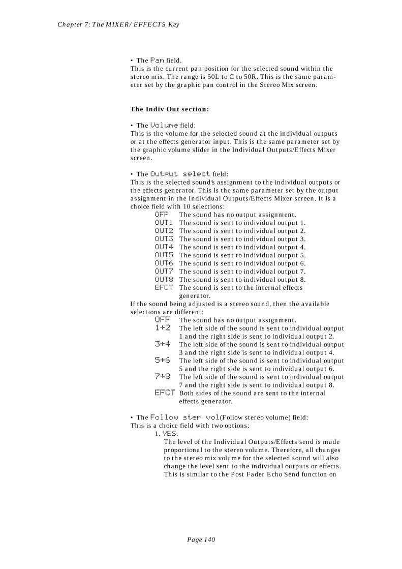
Page 140
Chapter 7: The MIXER/EFFECTS Key
• The Pan field.This is the current pan position for the selected sound within thestereo mix. The range is 50L to C to 50R. This is the same param-eter set by the graphic pan control in the Stereo Mix screen.
The Indiv Out section:
• The Volume field:This is the volume for the selected sound at the individual outputsor at the effects generator input. This is the same parameter set bythe graphic volume slider in the Individual Outputs/Effects Mixerscreen.
• The Output select field:This is the selected sound’s assignment to the individual outputs orthe effects generator. This is the same parameter set by the outputassignment in the Individual Outputs/Effects Mixer screen. It is achoice field with 10 selections:
OFF The sound has no output assignment.OUT1 The sound is sent to individual output 1.OUT2 The sound is sent to individual output 2.OUT3 The sound is sent to individual output 3.OUT4 The sound is sent to individual output 4.OUT5 The sound is sent to individual output 5.OUT6 The sound is sent to individual output 6.OUT7 The sound is sent to individual output 7.OUT8 The sound is sent to individual output 8.EFCT The sound is sent to the internal effects
generator.If the sound being adjusted is a stereo sound, then the availableselections are different:
OFF The sound has no output assignment.1+2 The left side of the sound is sent to individual output
1 and the right side is sent to individual output 2.3+4 The left side of the sound is sent to individual output
3 and the right side is sent to individual output 4.5+6 The left side of the sound is sent to individual output
5 and the right side is sent to individual output 6.7+8 The left side of the sound is sent to individual output
7 and the right side is sent to individual output 8.EFCT Both sides of the sound are sent to the internal
effects generator.
• The Follow ster vol(Follow stereo volume) field:This is a choice field with two options:
1. YES:The level of the Individual Outputs/Effects send is madeproportional to the stereo volume. Therefore, all changesto the stereo mix volume for the selected sound will alsochange the level sent to the individual outputs or effects.This is similar to the Post Fader Echo Send function on
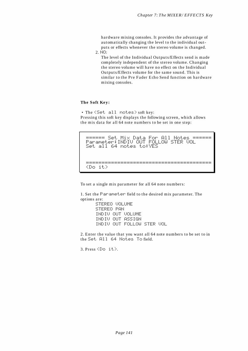
Page 141
Chapter 7: The MIXER/EFFECTS Key
hardware mixing consoles. It provides the advantage ofautomatically changing the level to the individual out-puts or effects whenever the stereo volume is changed.
2. NO:The level of the Individual Outputs/Effects send is madecompletely independent of the stereo volume. Changingthe stereo volume will have no effect on the IndividualOutputs/Effects volume for the same sound. This issimilar to the Pre Fader Echo Send function on hardwaremixing consoles.
The Soft Key:
• The <Set all notes> soft key:Pressing this soft key displays the following screen, which allowsthe mix data for all 64 note numbers to be set in one step:
====== Set Mix Data For All Notes ======Parameter:INDIV OUT FOLLOW STER VOLSet all 64 notes to:YES
========================================<Do it>
To set a single mix parameter for all 64 note numbers:
1. Set the Parameter field to the desired mix parameter. Theoptions are:
STEREO VOLUME
STEREO PAN
INDIV OUT VOLUME
INDIV OUT ASSIGN
INDIV OUT FOLLOW STER VOL
2. Enter the value that you want all 64 note numbers to be set to inthe Set All 64 Notes To field.
3. Press <Do it>.
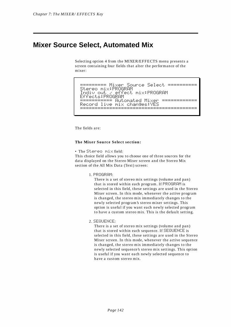
Page 142
Chapter 7: The MIXER/EFFECTS Key
Mixer Source Select, Automated Mix
Selecting option 4 from the MIXER/EFFECTS menu presents ascreen containing four fields that alter the performance of themixer:
========= Mixer Source Select ==========Stereo mix:PROGRAMIndiv out / effect mix:PROGRAMEffects:PROGRAM=========== Automated Mixer ============Record live mix changes:YES========================================
The fields are:
The Mixer Source Select section:
• The Stereo mix field:This choice field allows you to choose one of three sources for thedata displayed on the Stereo Mixer screen and the Stereo Mixsection of the All Mix Data (Text) screen:
1. PROGRAM:There is a set of stereo mix settings (volume and pan)that is stored within each program. If PROGRAM isselected in this field, these settings are used in the StereoMixer screen. In this mode, whenever the active programis changed, the stereo mix immediately changes to thenewly selected program’s stereo mixer settings. Thisoption is useful if you want each newly selected programto have a custom stereo mix. This is the default setting.
2. SEQUENCE:There is a set of stereo mix settings (volume and pan)that is stored within each sequence. If SEQUENCE isselected in this field, these settings are used in the StereoMixer screen. In this mode, whenever the active sequenceis changed, the stereo mix immediately changes to thenewly selected sequence’s stereo mix settings. This optionis useful if you want each newly selected sequence tohave a custom stereo mix.
Page 143
Chapter 7: The MIXER/EFFECTS Key
3. MASTER:There is a set of stereo mix settings (volume and pan)that is stored within each APG (all programs) file andthat applies globally to all sequences and programs. IfMASTER is selected in this field, this set of global data isused in the mixer screen. In this mode, the stereo mixersettings never change unless you change them, even ifthe active sequence or program is changed. This option isuseful for people who always want the mix settings tostay where they last put them. Note that these settingsmust be saved to the APS file before power is removed, orany changes mix changes will be lost.
• The Individual outs / effect mix field:This field works the same way as the Stereo mix field aboveexcept that the selection applies to the source of the IndividualOutputs/Effects Volume, Outputs/Effects Assignment, and FollowsStereo Volume data instead of the stereo volume and pan.
• The Effects field:This field works the same way as the Stereo mix field aboveexcept that the selection applies to the source of the data for theEffects screen instead of the Stereo Volume and Pan screen.
COMMENT: Whenever you change effect settings, any effectsignals that are still sounding (such as a long delay signalthat has not yet finished) will immediately be cut off. Thiscan cause a problem if SEQUENCE is selected while playinga song in song mode because the effect settings will change ateach sequence boundary in the song, causing termination ofany decaying delay signals at the sequence transition. Asimilar problem occurs if PROGRAM is controlling the effectsgenerator and you change programs while a sequence isplaying. Keep these issues in mind when creating effectschanges in mid-sequence or mid-song.
The contents of these 3 fields are saved in APS files.
The Automated mixer section:
• The Record live mix changes field:This is a choice field and has two options:
1. YES:If you’re recording on a drum track, all real-time changesmade to the volume or pan in the Stereo Mix screen (or tothe volume in the Individual Outputs/Effects Mixerscreen) are recorded, just as with an automated mixer.When played back, the mixer settings will change exactlyas they did while recording, both audibly and visually onthe graphic screens. These movements are stored like
Page 144
Chapter 7: The MIXER/EFFECTS Key
MIDI continuous controllers, as a series of many discreteevents (in this case, STEREO VOLUME, STEREO PAN,or OUTPUT/EFFECT VOLUME system exclusiveevents). These discrete events can be edited in detail inStep Edit mode.
2. NO:Real time mixer changes are not recorded. If prerecordedreal time mix changes already exist in drum tracks, theyare ignored.
COMMENT: The changes to the stereo mix volume and panwill only be recorded or played back if the Stereo Mixfield in the Mixer Source Select section of the screen is set toSEQUENCE. Likewise, the volume slider movements in theIndividual Outputs/Effects Mixer will only be recorded orplayed back if the Indiv Out/Effects Mix field in the MixerSource Select section of the screen is set to SEQUENCE.
COMMENT: If you use overdub mode to add mix changes toa region of the track where previous mix changes exist, theold changes are not erased, but rather the new changes willbe added in between the old ones, producing unpredictableresults. For this reason, it is a good idea to record yourautomated mix data on its own separate drum track, thenalways use record mode (not overdub mode) to punch-in anymix changes. This will automatically erase the old changesthroughout the punch-in region, but since the mix changesare on a separate track, any drum notes will not be erased.
COMMENT: A large number of these mix change events cancause minor slowing of playback due to the large processingrequirement. To reduce the number of these events, increasethe Minimum Change field’s setting for these event types(in the MIDI Input Filter screen) to as high a number asacceptable before recording mix changes. This will thin outthe mix data during recording, lessening the processingrequirement in playback.
COMMENT: As with any other mid-sequence controlchanges, these mix changes only take effect when played in asequence. This means that if you play a section of a sequencecontaining a specific controller event, the last played value ofthat controller will remain until another occurrence of thesame controller is played, even if you stop the sequence andstart playing it from another location. Because of this,whenever you use one of these events within a sequence, it isimportant to insert another event of the same type at thebeginning of the sequence to set the volume, pan or mixer/effects setting to an initial value.
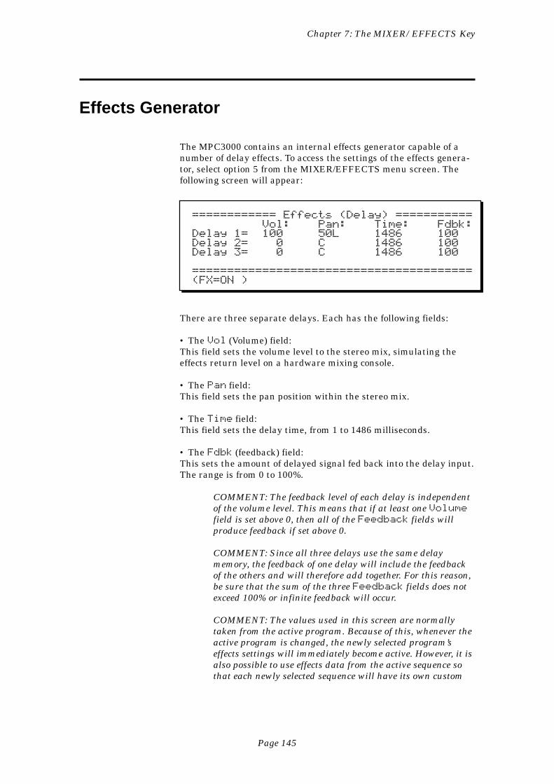
Page 145
Chapter 7: The MIXER/EFFECTS Key
Effects Generator
The MPC3000 contains an internal effects generator capable of anumber of delay effects. To access the settings of the effects genera-tor, select option 5 from the MIXER/EFFECTS menu screen. Thefollowing screen will appear:
============ Effects (Delay) =========== Vol: Pan: Time: Fdbk:Delay 1= 100 50L 1486 100Delay 2= 0 C 1486 100Delay 3= 0 C 1486 100
========================================(FX=ON )
There are three separate delays. Each has the following fields:
• The Vol (Volume) field:This field sets the volume level to the stereo mix, simulating theeffects return level on a hardware mixing console.
• The Pan field:This field sets the pan position within the stereo mix.
• The Time field:This field sets the delay time, from 1 to 1486 milliseconds.
• The Fdbk (feedback) field:This sets the amount of delayed signal fed back into the delay input.The range is from 0 to 100%.
COMMENT: The feedback level of each delay is independentof the volume level. This means that if at least one Volumefield is set above 0, then all of the Feedback fields willproduce feedback if set above 0.
COMMENT: Since all three delays use the same delaymemory, the feedback of one delay will include the feedbackof the others and will therefore add together. For this reason,be sure that the sum of the three Feedback fields does notexceed 100% or infinite feedback will occur.
COMMENT: The values used in this screen are normallytaken from the active program. Because of this, whenever theactive program is changed, the newly selected program’seffects settings will immediately become active. However, it isalso possible to use effects data from the active sequence sothat each newly selected sequence will have its own custom
Page 146
Chapter 7: The MIXER/EFFECTS Key
effects data, or to use a single master set of effects data sothat the selected effect never changes. This choice may bemade in the Mixer Source Select fields, accessed by pressingoption 4 from the MIXER/EFFECTS menu.

Page 147
Chapter 8: Creating and Editing Sounds
Chapter 8:Creating and
Editing Sounds
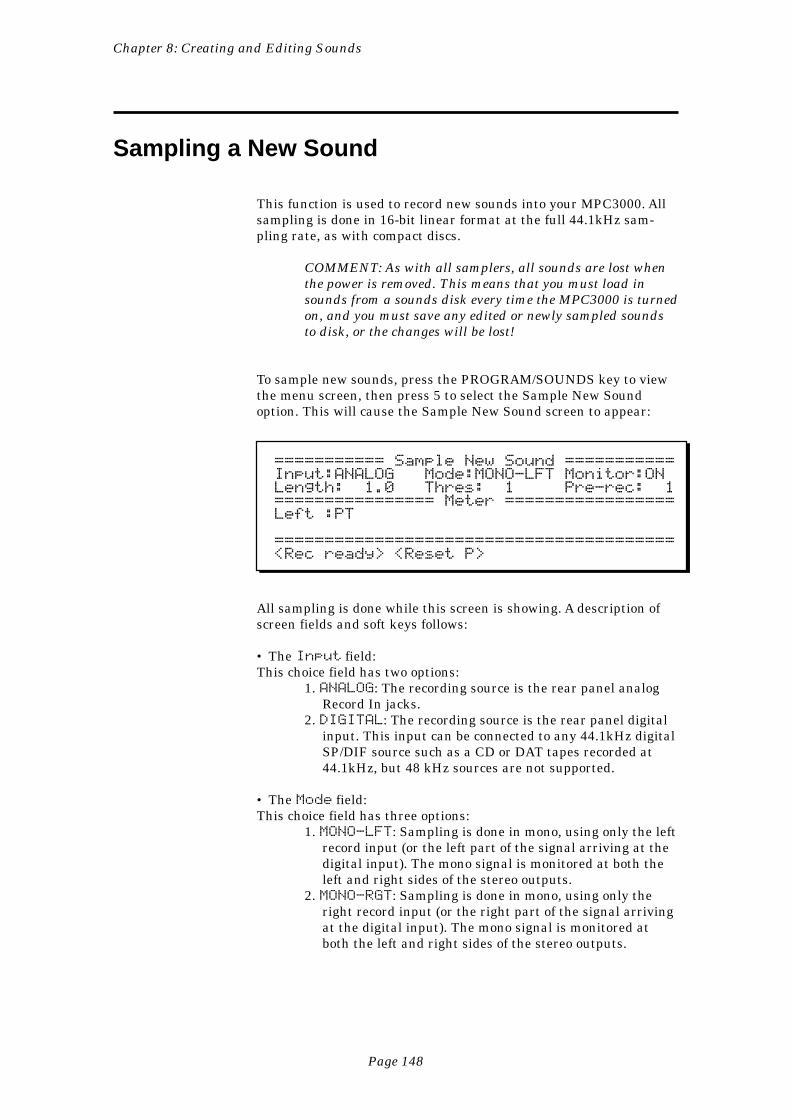
Page 148
Chapter 8: Creating and Editing Sounds
Sampling a New Sound
This function is used to record new sounds into your MPC3000. Allsampling is done in 16-bit linear format at the full 44.1kHz sam-pling rate, as with compact discs.
COMMENT: As with all samplers, all sounds are lost whenthe power is removed. This means that you must load insounds from a sounds disk every time the MPC3000 is turnedon, and you must save any edited or newly sampled soundsto disk, or the changes will be lost!
To sample new sounds, press the PROGRAM/SOUNDS key to viewthe menu screen, then press 5 to select the Sample New Soundoption. This will cause the Sample New Sound screen to appear:
=========== Sample New Sound ===========Input:ANALOG Mode:MONO-LFT Monitor:ONLength: 1.0 Thres: 1 Pre-rec: 1================ Meter =================Left :PT
========================================<Rec ready> <Reset P>
All sampling is done while this screen is showing. A description ofscreen fields and soft keys follows:
• The Input field:This choice field has two options:
1. ANALOG: The recording source is the rear panel analogRecord In jacks.
2. DIGITAL: The recording source is the rear panel digitalinput. This input can be connected to any 44.1kHz digitalSP/DIF source such as a CD or DAT tapes recorded at44.1kHz, but 48 kHz sources are not supported.
• The Mode field:This choice field has three options:
1. MONO-LFT: Sampling is done in mono, using only the leftrecord input (or the left part of the signal arriving at thedigital input). The mono signal is monitored at both theleft and right sides of the stereo outputs.
2. MONO-RGT: Sampling is done in mono, using only theright record input (or the right part of the signal arrivingat the digital input). The mono signal is monitored atboth the left and right sides of the stereo outputs.
Page 149
Chapter 8: Creating and Editing Sounds
3. STEREO: Sampling is done in stereo, using both the leftand right sampling inputs (or both parts of the signalarriving at the digital input).
• The Monitor field:This choice field has two options: ON and OFF. If ON, the signal fromthe sampling input is heard in the stereo mix outputs. If OFF, it isnot. If you are sampling with a microphone in the same room as thespeakers, select OFF to avoid audio feedback. Otherwise, select ONto hear the incoming signal in the stereo mix.
• The Length field:This field is used to specify the total recording time to be allocatedto the new sample, in seconds (and 0.1 seconds). Any number can beentered here up to the maximum available sampling time. In a non-expanded MPC3000, the maximum sampling time is 21.9 secondsmono or 10.9 seconds stereo. In a fully expanded MPC3000 (total 16megabytes) the maximum sampling time is 188.3 seconds mono or94.1 seconds stereo.
COMMENT: If you frequently find that you need morememory even when all sounds are deleted, you may want toadd more memory to the MPC3000. See the section “Expand-ing the Sound Memory” in the Appendix for informationabout how to do this.
COMMENT: Although the maximum sampling time islimited only by available sound memory, the maximumsound file size that can fit on a floppy disk is 16.4 secondsmono or 8.2 seconds stereo. If a sound is larger than this, itwon’t fit on a single floppy and the MPC3000 cannot splitsingle sound files over two or more floppies. If you need tocreate longer sounds and save them to disk, you must use anexternal hard disk connected to the SCSI port.
• The Thres (Threshold) field:This sets the threshold above which recording will begin once <Recready> has been pressed. The range is 0-100% of full scale. A goodsetting to start with is 1%. Setting Thres to 0 will cause recordingto begin as soon as <Rec ready> is pressed.
• The Pre-Rec (Pre-Record) field:When sampling, a small amount of time before the level threshold isexceeded is also recorded, insuring that even the low level start ofthe sound is retained. This field is used to set that amount of pre-record time, in milliseconds. For example, to record 10 millisecondsbefore the audio threshold is exceeded, enter 10 here. The defaultvalue here is 1 millisecond, which is adequate for most sharp attacksounds like drums.
COMMENT: When played back, the sound starts playingfrom the point at which the threshold was exceeded
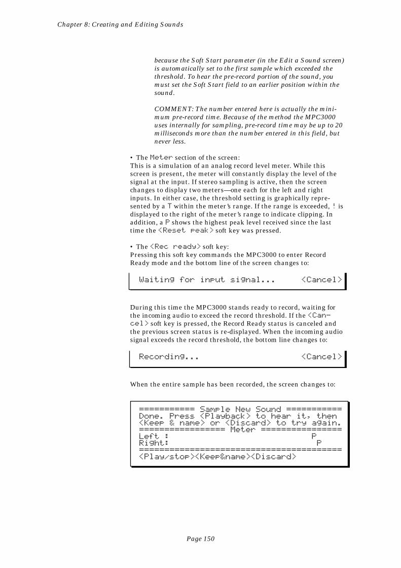
Page 150
Chapter 8: Creating and Editing Sounds
because the Soft Start parameter (in the Edit a Sound screen)is automatically set to the first sample which exceeded thethreshold. To hear the pre-record portion of the sound, youmust set the Soft Start field to an earlier position within thesound.
COMMENT: The number entered here is actually the mini-mum pre-record time. Because of the method the MPC3000uses internally for sampling, pre-record time may be up to 20milliseconds more than the number entered in this field, butnever less.
• The Meter section of the screen:This is a simulation of an analog record level meter. While thisscreen is present, the meter will constantly display the level of thesignal at the input. If stereo sampling is active, then the screenchanges to display two meters—one each for the left and rightinputs. In either case, the threshold setting is graphically repre-sented by a T within the meter’s range. If the range is exceeded, ! isdisplayed to the right of the meter’s range to indicate clipping. Inaddition, a P shows the highest peak level received since the lasttime the <Reset peak> soft key was pressed.
• The <Rec ready> soft key:Pressing this soft key commands the MPC3000 to enter RecordReady mode and the bottom line of the screen changes to:
Waiting for input signal... <Cancel>
During this time the MPC3000 stands ready to record, waiting forthe incoming audio to exceed the record threshold. If the <Can-cel> soft key is pressed, the Record Ready status is canceled andthe previous screen status is re-displayed. When the incoming audiosignal exceeds the record threshold, the bottom line changes to:
Recording... <Cancel>
When the entire sample has been recorded, the screen changes to:
=========== Sample New Sound ===========Done. Press <Playback> to hear it, then<Keep & name> or <Discard> to try again.================= Meter ================Left : PRight: P========================================<Play/stop><Keep&name><Discard>
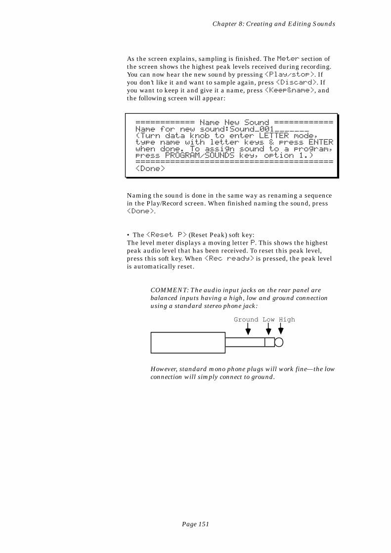
Page 151
Chapter 8: Creating and Editing Sounds
As the screen explains, sampling is finished. The Meter section ofthe screen shows the highest peak levels received during recording.You can now hear the new sound by pressing <Play/stop>. Ifyou don’t like it and want to sample again, press <Discard>. Ifyou want to keep it and give it a name, press <Keep&name>, andthe following screen will appear:
============ Name New Sound ============Name for new sound:Sound_001_______(Turn data knob to enter LETTER mode,type name with letter keys & press ENTERwhen done. To assign sound to a program,press PROGRAM/SOUNDS key, option 1.)========================================<Done>
Naming the sound is done in the same way as renaming a sequencein the Play/Record screen. When finished naming the sound, press<Done>.
• The <Reset P> (Reset Peak) soft key:The level meter displays a moving letter P. This shows the highestpeak audio level that has been received. To reset this peak level,press this soft key. When <Rec ready> is pressed, the peak levelis automatically reset.
COMMENT: The audio input jacks on the rear panel arebalanced inputs having a high, low and ground connectionusing a standard stereo phone jack:
Ground Low High
However, standard mono phone plugs will work fine—the lowconnection will simply connect to ground.
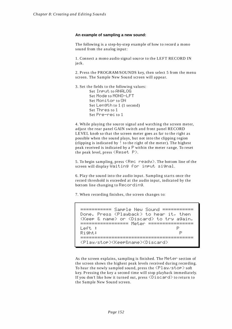
Page 152
Chapter 8: Creating and Editing Sounds
An example of sampling a new sound:
The following is a step-by-step example of how to record a monosound from the analog input:
1. Connect a mono audio signal source to the LEFT RECORD INjack.
2. Press the PROGRAM/SOUNDS key, then select 5 from the menuscreen. The Sample New Sound screen will appear.
3. Set the fields to the following values:Set Input to ANALOGSet Mode to MONO-LFTSet Monitor to ONSet Length to 1 (1 second)Set Thres to 1Set Pre-rec to 1
4. While playing the source signal and watching the screen meter,adjust the rear panel GAIN switch and front panel RECORDLEVEL knob so that the screen meter goes as far to the right aspossible when the sound plays, but not into the clipping region(clipping is indicated by ! to the right of the meter). The highestpeak received is indicated by a P within the meter range. To resetthe peak level, press <Reset P>.
5. To begin sampling, press <Rec ready>. The bottom line of thescreen will display Waiting for input signal.
6. Play the sound into the audio input. Sampling starts once therecord threshold is exceeded at the audio input, indicated by thebottom line changing to Recording.
7. When recording finishes, the screen changes to:
=========== Sample New Sound ===========
Done. Press <Playback> to hear it, then
<Keep & name> or <Discard> to try again.
================= Meter ================
Left : P
Right: P
========================================
<Play/stop><Keep&name><Discard>
As the screen explains, sampling is finished. The Meter section ofthe screen shows the highest peak levels received during recording.To hear the newly sampled sound, press the <Play/stop> softkey. Pressing the key a second time will stop playback immediately.If you don’t like how it turned out, press <Discard> to return tothe Sample New Sound screen.
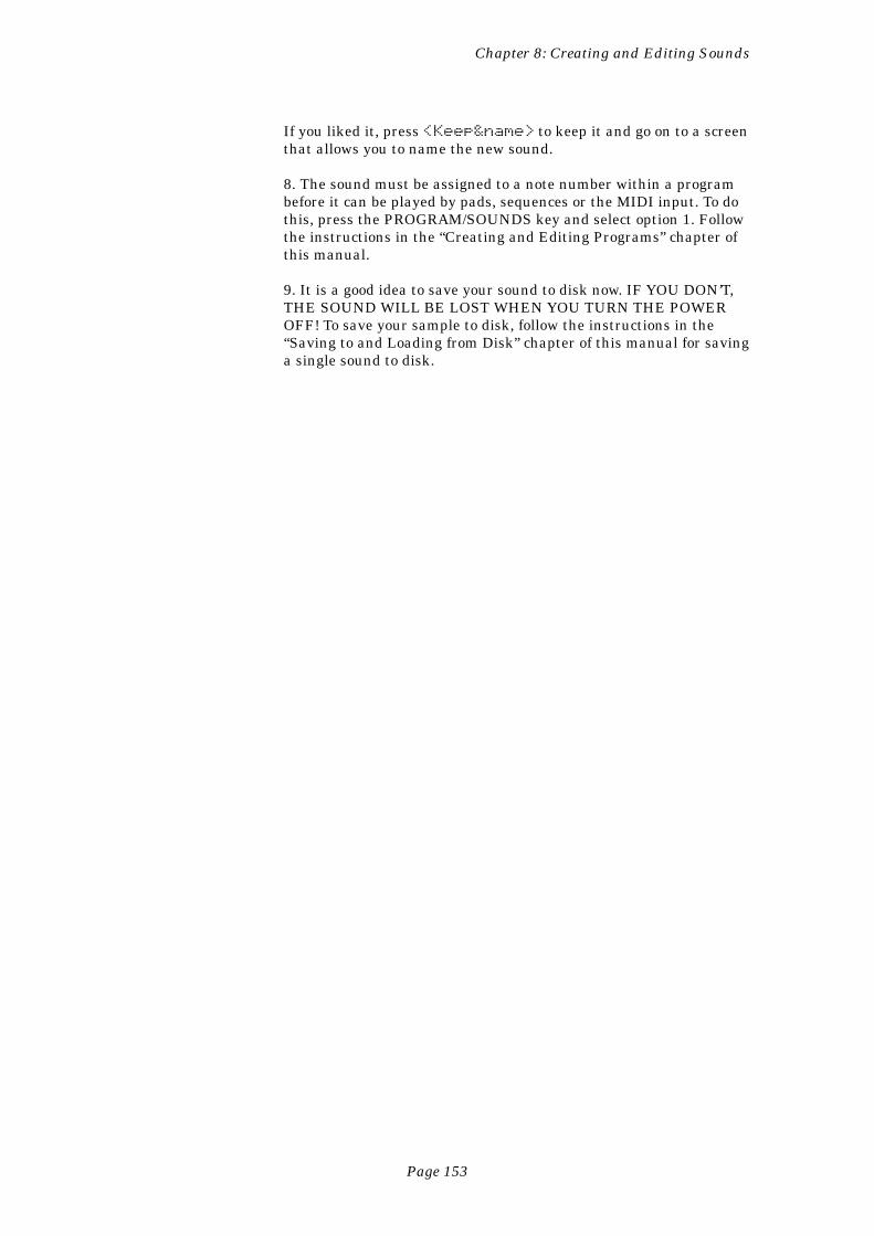
Page 153
Chapter 8: Creating and Editing Sounds
If you liked it, press <Keep&name> to keep it and go on to a screenthat allows you to name the new sound.
8. The sound must be assigned to a note number within a programbefore it can be played by pads, sequences or the MIDI input. To dothis, press the PROGRAM/SOUNDS key and select option 1. Followthe instructions in the “Creating and Editing Programs” chapter ofthis manual.
9. It is a good idea to save your sound to disk now. IF YOU DON’T,THE SOUND WILL BE LOST WHEN YOU TURN THE POWEROFF! To save your sample to disk, follow the instructions in the“Saving to and Loading from Disk” chapter of this manual for savinga single sound to disk.
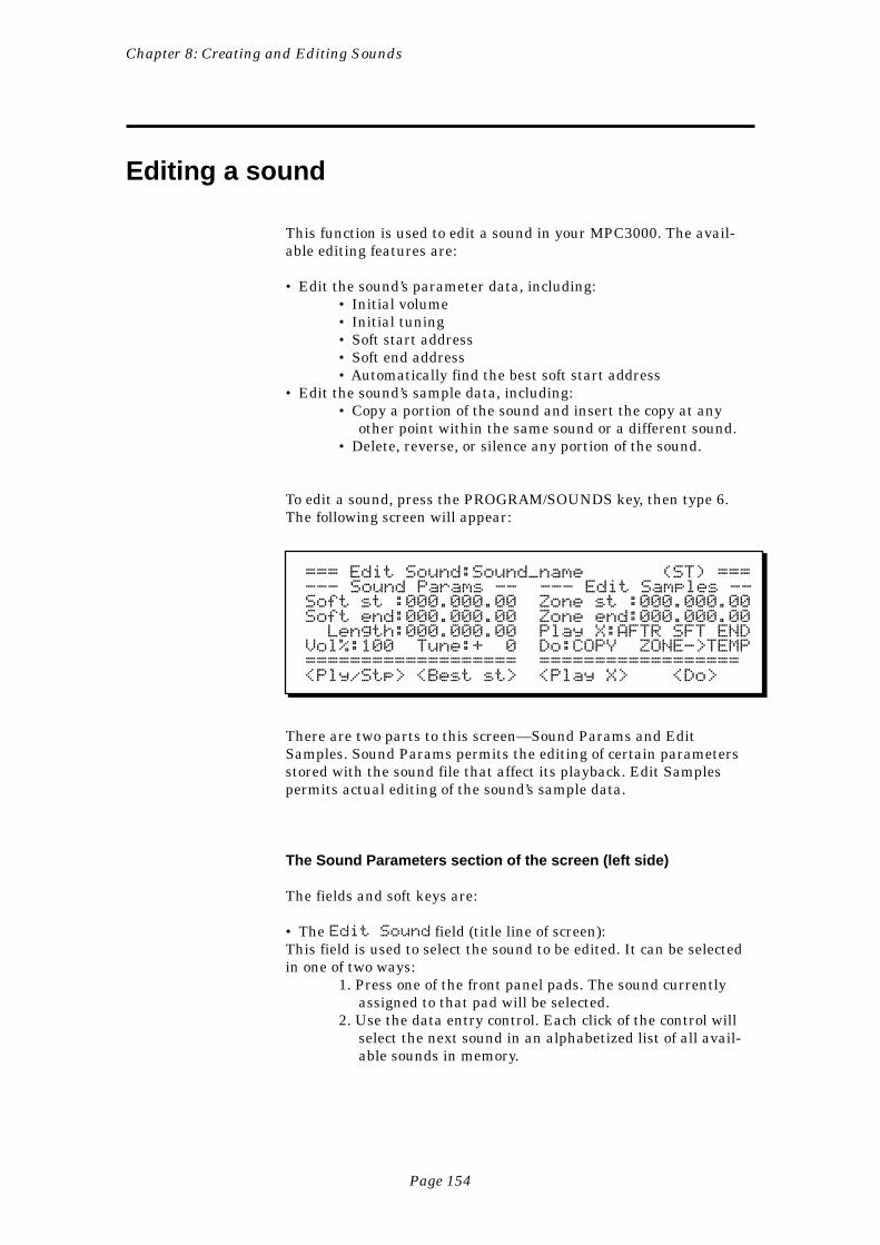
Page 154
Chapter 8: Creating and Editing Sounds
Editing a sound
This function is used to edit a sound in your MPC3000. The avail-able editing features are:
• Edit the sound’s parameter data, including:• Initial volume• Initial tuning• Soft start address• Soft end address• Automatically find the best soft start address
• Edit the sound’s sample data, including:• Copy a portion of the sound and insert the copy at any
other point within the same sound or a different sound.• Delete, reverse, or silence any portion of the sound.
To edit a sound, press the PROGRAM/SOUNDS key, then type 6.The following screen will appear:
=== Edit Sound:Sound_name (ST) ===--- Sound Params -- --- Edit Samples --Soft st :000.000.00 Zone st :000.000.00Soft end:000.000.00 Zone end:000.000.00 Length:000.000.00 Play X:AFTR SFT ENDVol%:100 Tune:+ 0 Do:COPY ZONE->TEMP=================== ==================<Ply/Stp> <Best st> <Play X> <Do>
There are two parts to this screen—Sound Params and EditSamples. Sound Params permits the editing of certain parametersstored with the sound file that affect its playback. Edit Samplespermits actual editing of the sound’s sample data.
The Sound Parameters section of the screen (left side)
The fields and soft keys are:
• The Edit Sound field (title line of screen):This field is used to select the sound to be edited. It can be selectedin one of two ways:
1. Press one of the front panel pads. The sound currentlyassigned to that pad will be selected.
2. Use the data entry control. Each click of the control willselect the next sound in an alphabetized list of all avail-able sounds in memory.
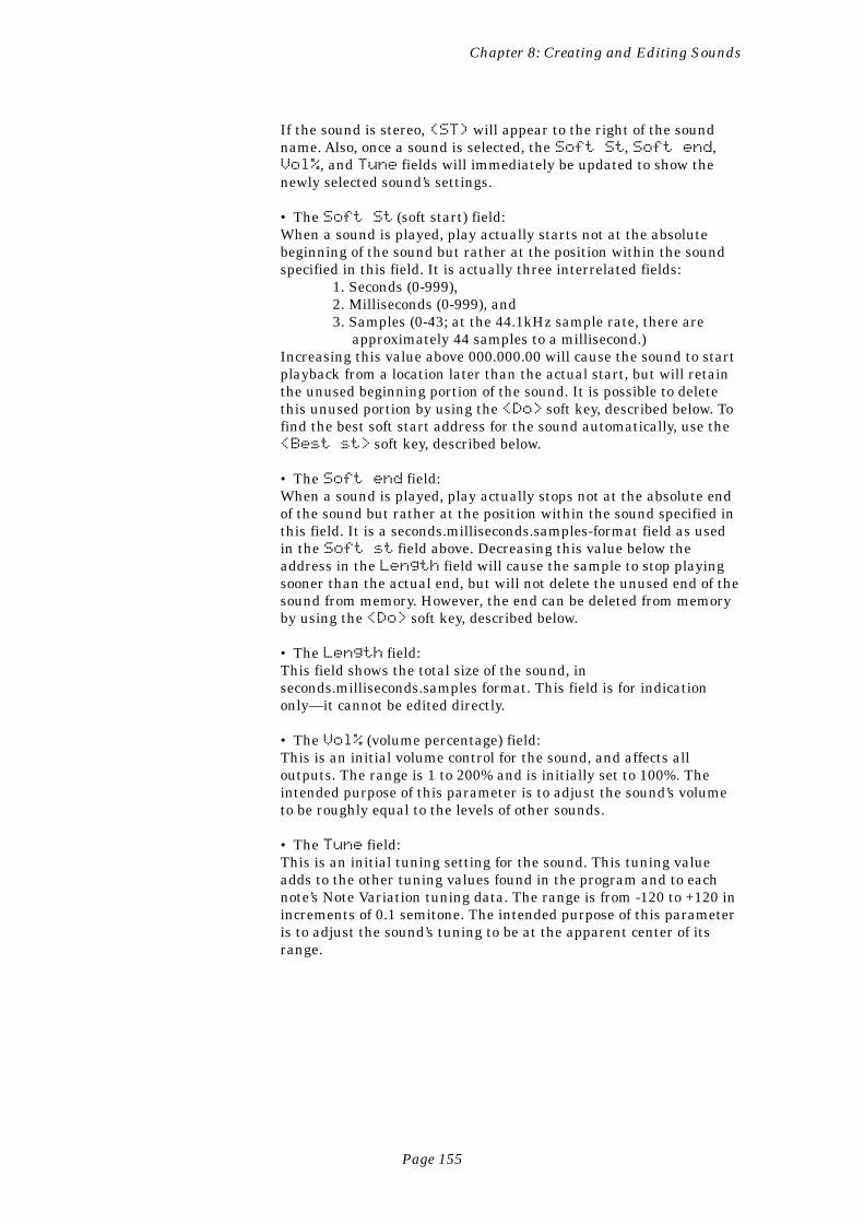
Page 155
Chapter 8: Creating and Editing Sounds
If the sound is stereo, (ST) will appear to the right of the soundname. Also, once a sound is selected, the Soft St, Soft end,Vol%, and Tune fields will immediately be updated to show thenewly selected sound’s settings.
• The Soft St (soft start) field:When a sound is played, play actually starts not at the absolutebeginning of the sound but rather at the position within the soundspecified in this field. It is actually three interrelated fields:
1. Seconds (0-999),2. Milliseconds (0-999), and3. Samples (0-43; at the 44.1kHz sample rate, there are
approximately 44 samples to a millisecond.)Increasing this value above 000.000.00 will cause the sound to startplayback from a location later than the actual start, but will retainthe unused beginning portion of the sound. It is possible to deletethis unused portion by using the <Do> soft key, described below. Tofind the best soft start address for the sound automatically, use the<Best st> soft key, described below.
• The Soft end field:When a sound is played, play actually stops not at the absolute endof the sound but rather at the position within the sound specified inthis field. It is a seconds.milliseconds.samples-format field as usedin the Soft st field above. Decreasing this value below theaddress in the Length field will cause the sample to stop playingsooner than the actual end, but will not delete the unused end of thesound from memory. However, the end can be deleted from memoryby using the <Do> soft key, described below.
• The Length field:This field shows the total size of the sound, inseconds.milliseconds.samples format. This field is for indicationonly—it cannot be edited directly.
• The Vol% (volume percentage) field:This is an initial volume control for the sound, and affects alloutputs. The range is 1 to 200% and is initially set to 100%. Theintended purpose of this parameter is to adjust the sound’s volumeto be roughly equal to the levels of other sounds.
• The Tune field:This is an initial tuning setting for the sound. This tuning valueadds to the other tuning values found in the program and to eachnote’s Note Variation tuning data. The range is from -120 to +120 inincrements of 0.1 semitone. The intended purpose of this parameteris to adjust the sound’s tuning to be at the apparent center of itsrange.
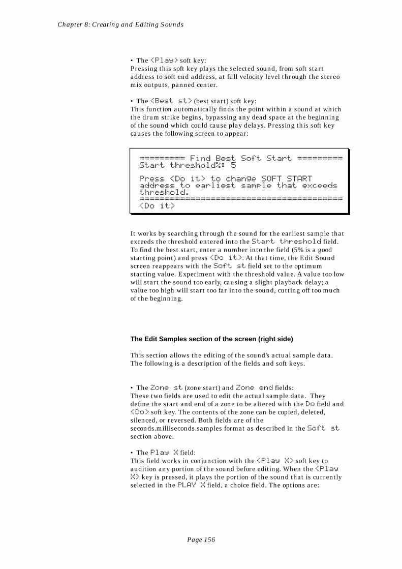
Page 156
Chapter 8: Creating and Editing Sounds
• The <Play> soft key:Pressing this soft key plays the selected sound, from soft startaddress to soft end address, at full velocity level through the stereomix outputs, panned center.
• The <Best st> (best start) soft key:This function automatically finds the point within a sound at whichthe drum strike begins, bypassing any dead space at the beginningof the sound which could cause play delays. Pressing this soft keycauses the following screen to appear:
========= Find Best Soft Start =========Start threshold%: 5
Press <Do it> to change SOFT STARTaddress to earliest sample that exceedsthreshold.========================================<Do it>
It works by searching through the sound for the earliest sample thatexceeds the threshold entered into the Start threshold field.To find the best start, enter a number into the field (5% is a goodstarting point) and press <Do it>. At that time, the Edit Soundscreen reappears with the Soft st field set to the optimumstarting value. Experiment with the threshold value. A value too lowwill start the sound too early, causing a slight playback delay; avalue too high will start too far into the sound, cutting off too muchof the beginning.
The Edit Samples section of the screen (right side)
This section allows the editing of the sound’s actual sample data.The following is a description of the fields and soft keys.
• The Zone st (zone start) and Zone end fields:These two fields are used to edit the actual sample data. Theydefine the start and end of a zone to be altered with the Do field and<Do> soft key. The contents of the zone can be copied, deleted,silenced, or reversed. Both fields are of theseconds.milliseconds.samples format as described in the Soft stsection above.
• The Play X field:This field works in conjunction with the <Play X> soft key toaudition any portion of the sound before editing. When the <PlayX> key is pressed, it plays the portion of the sound that is currentlyselected in the PLAY X field, a choice field. The options are:
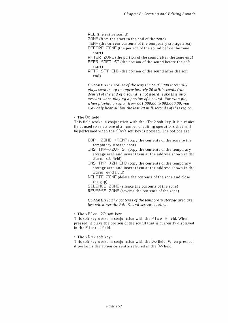
Page 157
Chapter 8: Creating and Editing Sounds
ALL (the entire sound)ZONE (from the start to the end of the zone)TEMP (the current contents of the temporary storage area)BEFORE ZONE (the portion of the sound before the zone
start)AFTER ZONE (the portion of the sound after the zone end)BEFR SOFT ST (the portion of the sound before the soft
start)AFTR SFT END (the portion of the sound after the soft
end)
COMMENT: Because of the way the MPC3000 internallyplays sounds, up to approximately 20 milliseconds (ran-domly) of the end of a sound is not heard. Take this intoaccount when playing a portion of a sound. For example,when playing a region from 001.000.00 to 002.000.00, youmay only hear all but the last 20 milliseconds of this region.
• The Do field:This field works in conjunction with the <Do> soft key. It is a choicefield, used to select one of a number of editing operations that willbe performed when the <Do> soft key is pressed. The options are:
COPY ZONE->TEMP (copy the contents of the zone to thetemporary storage area)
INS TMP->ZON ST (copy the contents of the temporarystorage area and insert them at the address shown in theZone st field)
INS TMP->ZN END (copy the contents of the temporarystorage area and insert them at the address shown in theZone end field)
DELETE ZONE (delete the contents of the zone and closethe gap)
SILENCE ZONE (silence the contents of the zone)REVERSE ZONE (reverse the contents of the zone)
COMMENT: The contents of the temporary storage area arelost whenever the Edit Sound screen is exited.
• The <Play X> soft key:This soft key works in conjunction with the Play X field. Whenpressed, it plays the portion of the sound that is currently displayedin the Play X field.
• The <Do> soft key:This soft key works in conjunction with the Do field. When pressed,it performs the action currently selected in the Do field.
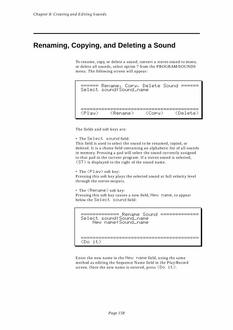
Page 158
Chapter 8: Creating and Editing Sounds
Renaming, Copying, and Deleting a Sound
To rename, copy, or delete a sound, convert a stereo sound to mono,or delete all sounds, select option 7 from the PROGRAM/SOUNDSmenu. The following screen will appear:
====== Rename, Copy, Delete Sound ======Select sound:Sound_name
========================================<Play> <Rename> <Copy> <Delete>
The fields and soft keys are:
• The Select sound field:This field is used to select the sound to be renamed, copied, ordeleted. It is a choice field containing an alphabetic list of all soundsin memory. Pressing a pad will select the sound currently assignedto that pad in the current program. If a stereo sound is selected,(ST) is displayed to the right of the sound name.
• The <Play> soft key:Pressing this soft key plays the selected sound at full velocity levelthrough the stereo outputs.
• The <Rename> soft key:Pressing this soft key causes a new field, New name, to appearbelow the Select sound field:
============= Rename Sound =============Select sound:Sound_name New name:Sound_name
========================================<Do it>
Enter the new name in the New name field, using the samemethod as editing the Sequence Name field in the Play/Recordscreen. Once the new name is entered, press <Do it>.
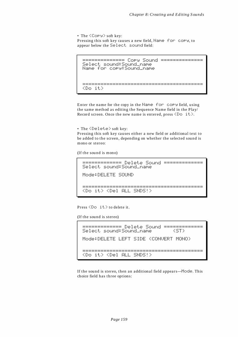
Page 159
Chapter 8: Creating and Editing Sounds
• The <Copy> soft key:Pressing this soft key causes a new field, Name for copy, toappear below the Select sound field:
============== Copy Sound ==============Select sound:Sound_nameName for copy:Sound_name
========================================<Do it>
Enter the name for the copy in the Name for copy field, usingthe same method as editing the Sequence Name field in the Play/Record screen. Once the new name is entered, press <Do it>.
• The <Delete> soft key:Pressing this soft key causes either a new field or additional text tobe added to the screen, depending on whether the selected sound ismono or stereo:
(If the sound is mono)
============= Delete Sound =============Select sound:Sound_name
Mode:DELETE SOUND
========================================<Do it> <Del ALL SNDS!>
Press <Do it> to delete it.
(If the sound is stereo)
============= Delete Sound =============Select sound:Sound_name (ST)
Mode:DELETE LEFT SIDE (CONVERT MONO)
========================================<Do it> <Del ALL SNDS!>
If the sound is stereo, then an additional field appears—Mode. Thischoice field has three options:
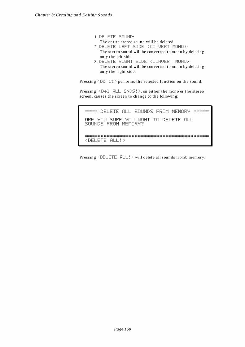
Page 160
Chapter 8: Creating and Editing Sounds
1. DELETE SOUND:The entire stereo sound will be deleted.
2. DELETE LEFT SIDE (CONVERT MONO):The stereo sound will be converted to mono by deletingonly the left side.
3. DELETE RIGHT SIDE (CONVERT MONO):The stereo sound will be converted to mono by deletingonly the right side.
Pressing <Do it> performs the selected function on the sound.
Pressing <Del ALL SNDS!>, on either the mono or the stereoscreen, causes the screen to change to the following:
==== DELETE ALL SOUNDS FROM MEMORY =====
ARE YOU SURE YOU WANT TO DELETE ALLSOUNDS FROM MEMORY?
========================================<DELETE ALL!>
Pressing <DELETE ALL!> will delete all sounds fromb memory.
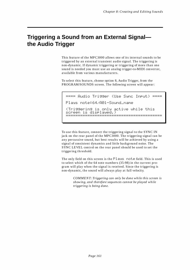
Page 161
Chapter 8: Creating and Editing Sounds
Triggering a Sound from an External Signal—the Audio Trigger
This feature of the MPC3000 allows one of its internal sounds to betriggered by an external transient audio signal. The triggering isnon-dynamic. If dynamic triggering or triggering of more than onesound is needed you must use an analog trigger-to-MIDI converter,available from various manufacturers.
To select this feature, choose option 8, Audio Trigger, from thePROGRAM/SOUNDS screen. The following screen will appear:
==== Audio Trigger (Use Sync Input) ====
Plays note:64/A01-Sound_name
(Triggering is only active while thisscreen is displayed.)========================================
To use this feature, connect the triggering signal to the SYNC INjack on the rear panel of the MPC3000. The triggering signal can beany percussive sound, but best results will be achieved by using asignal of consistent dynamics and little background noise. TheSYNC LEVEL control on the rear panel should be used to set thetriggering threshold.
The only field on this screen is the Plays note field. This is usedto select which of the 64 note numbers (35-98) in the current pro-gram will play when the signal is received. Since the triggering isnon-dynamic, the sound will always play at full velocity.
COMMENT: Triggering can only be done while this screen isshowing, and therefore sequences cannot be played whiletriggering is being done.

Page 163
Chapter 9: Saving to and Loading from Disk
Chapter 9:Saving to and
Loading from Disk
Page 164
Chapter 9: Saving to and Loading from Disk
Overview
The MPC3000 has a built-in 3-1/2" disk drive for storing data. Thischapter describes the procedures for saving and loading the varioustypes of files. Since the MPC3000 loses all sequence and sound datawhen the power is removed, it is important always to save anychanges to disk before turning the power off.
The five different file types:
All data are stored to disk as files. All disk files used on theMPC3000 use a 16-character file name, which you assign to the filewhen it is saved to disk. In addition, there is a three-letter fileextension, which is used to differentiate the file types. The fivetypes of files (and file name extensions) are:
1. FILENAME.SEQ: This file contains a single sequence.2. FILENAME.ALL: This file contains all 99 sequences and all 20songs.3. FILENAME.SND: This file contains a single drum sound.4. FILENAME.PGM: This file holds the contents of a single programand the names of all sounds used by that program, but it does notcontain the actual sounds.5. FILENAME.APS: This file holds the contents of all 24 programsand the names of all sounds used in those programs, but it does notcontain the actual sounds.6. FILENAME.PAR: This file contains all settings that are normallyretained in the MPC3000, even when power is removed. Theseparameters are not saved within any other file type.
Before proceeding, be aware of these important points:
• When new disks are purchased, they are not formatted. Beforeusing the disks, you MUST format each one using the Format Diskoption from the DISK menu. Pre-formatted MS-DOS disks willwork, but they will save and load faster if you format them again onthe MPC3000.• The 3-1/2" disks used in the MPC3000 should be high density(HD) disks. It is also possible to use double-sided, double-densitydisks (2DD) for compatibility with the MPC60, but these hold only793K, whereas the HD disks hold 1.44MB.• NEVER REMOVE A DISK FROM THE DISK DRIVE WHILETHE LIGHT ON THE FRONT OF THE DISK DRIVE IS ON!
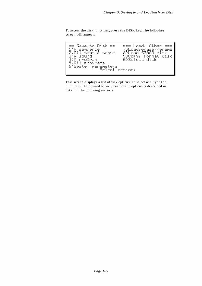
Page 165
Chapter 9: Saving to and Loading from Disk
To access the disk functions, press the DISK key. The followingscreen will appear:
== Save to Disk == === Load, Other ===1)A sequence 7)Load,erase,rename2)All seqs & songs 8)Load S3000 disk3)A sound 9)Copy, format disk4)A program 0)Select disk5)All programs6)System parameters Select option:
This screen displays a list of disk options. To select one, type thenumber of the desired option. Each of the options is described indetail in the following sections.
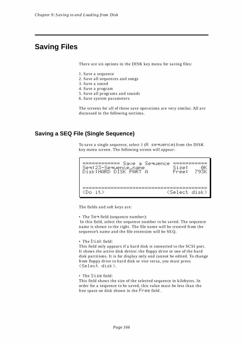
Page 166
Chapter 9: Saving to and Loading from Disk
Saving Files
There are six options in the DISK key menu for saving files:
1. Save a sequence2. Save all sequences and songs3. Save a sound4. Save a program5. Save all programs and sounds6. Save system parameters
The screens for all of these save operations are very similar. All arediscussed in the following sections.
Saving a SEQ File (Single Sequence)
To save a single sequence, select 1 (A sequence) from the DISKkey menu screen. The following screen will appear:
============ Save a Sequence ===========Seq:23-Sequence_name Size: 0KDisk:HARD DISK PART A Free: 793K
========================================<Do it> <Select disk>
The fields and soft keys are:
• The Seq field (sequence number): In this field, select the sequence number to be saved. The sequencename is shown to the right. The file name will be created from thesequence’s name and the file extension will be SEQ.
• The Disk field:This field only appears if a hard disk is connected to the SCSI port.It shows the active disk device: the floppy drive or one of the harddisk partitions. It is for display only and cannot be edited. To changefrom floppy drive to hard disk or vice versa, you must press<Select disk>.
• The Size field:This field shows the size of the selected sequence in kilobytes. Inorder for a sequence to be saved, this value must be less than thefree space on disk shown in the Free field .
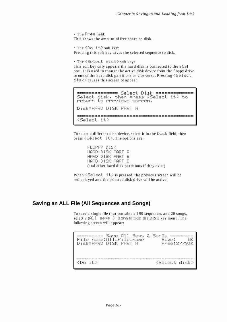
Page 167
Chapter 9: Saving to and Loading from Disk
• The Free field:This shows the amount of free space on disk.
• The <Do it> soft key:Pressing this soft key saves the selected sequence to disk.
• The <Select disk> soft key:This soft key only appears if a hard disk is connected to the SCSIport. It is used to change the active disk device from the floppy driveto one of the hard disk partitions or vice versa. Pressing <Selectdisk> causes this screen to appear:
============== Select Disk =============Select disk, then press <Select it> toreturn to previous screen.
Disk:HARD DISK PART A
========================================<Select it>
To select a different disk device, select it in the Disk field, thenpress <Select it>. The options are:
FLOPPY DISK
HARD DISK PART A
HARD DISK PART B
HARD DISK PART C
(and other hard disk partitions if they exist)
When <Select it> is pressed, the previous screen will beredisplayed and the selected disk drive will be active.
Saving an ALL File (All Sequences and Songs)
To save a single file that contains all 99 sequences and 20 songs,select 2 (All seqs & songs) from the DISK key menu. Thefollowing screen will appear:
========= Save All Seqs & Songs ========File name:All_file_name Size: 0KDisk:HARD DISK PART A Free:27793K
========================================<Do it> <Select disk>
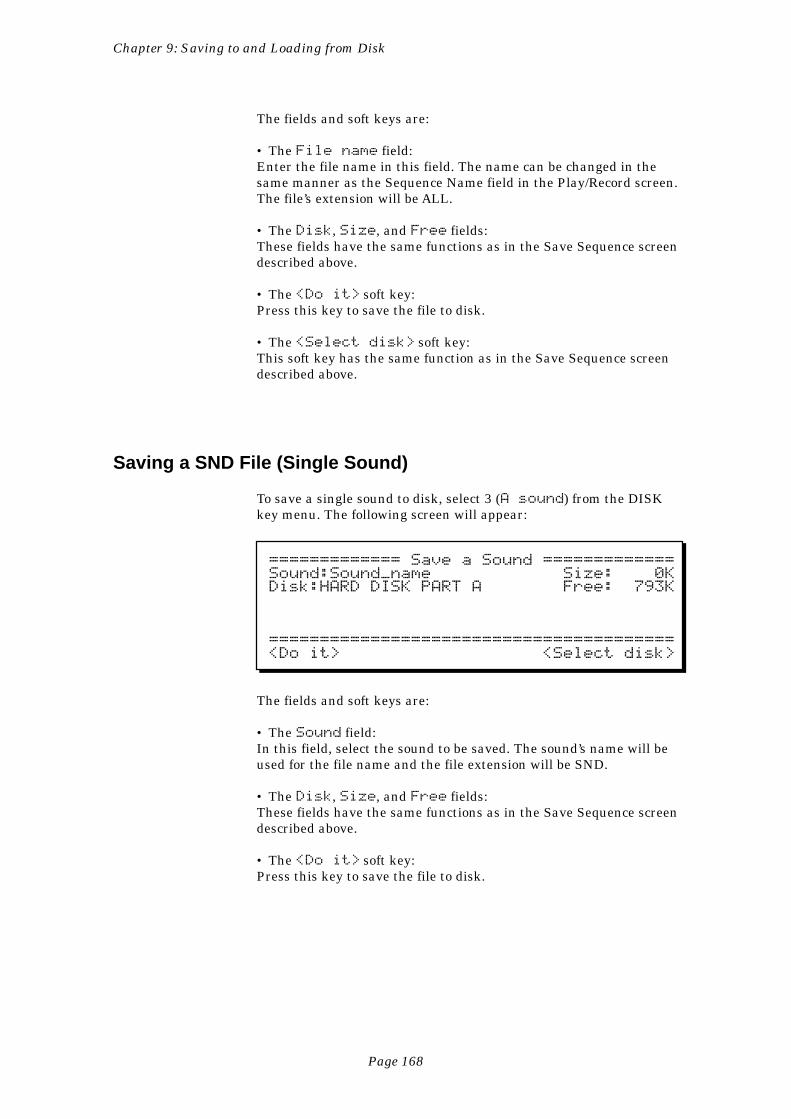
Page 168
Chapter 9: Saving to and Loading from Disk
The fields and soft keys are:
• The File name field:Enter the file name in this field. The name can be changed in thesame manner as the Sequence Name field in the Play/Record screen.The file’s extension will be ALL.
• The Disk, Size, and Free fields:These fields have the same functions as in the Save Sequence screendescribed above.
• The <Do it> soft key:Press this key to save the file to disk.
• The <Select disk> soft key:This soft key has the same function as in the Save Sequence screendescribed above.
Saving a SND File (Single Sound)
To save a single sound to disk, select 3 (A sound) from the DISKkey menu. The following screen will appear:
============= Save a Sound =============Sound:Sound_name Size: 0KDisk:HARD DISK PART A Free: 793K
========================================<Do it> <Select disk>
The fields and soft keys are:
• The Sound field:In this field, select the sound to be saved. The sound’s name will beused for the file name and the file extension will be SND.
• The Disk, Size, and Free fields:These fields have the same functions as in the Save Sequence screendescribed above.
• The <Do it> soft key:Press this key to save the file to disk.
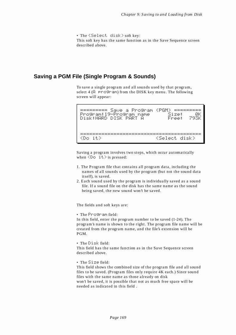
Page 169
Chapter 9: Saving to and Loading from Disk
• The <Select disk> soft key:This soft key has the same function as in the Save Sequence screendescribed above.
Saving a PGM File (Single Program & Sounds)
To save a single program and all sounds used by that program,select 4 (A program) from the DISK key menu. The followingscreen will appear:
========= Save a Program (PGM) =========Program:19-Program name Size: 0KDisk:HARD DISK PART A Free: 793K
========================================<Do it> <Select disk>
Saving a program involves two steps, which occur automaticallywhen <Do it> is pressed:
1. The Program file that contains all program data, including thenames of all sounds used by the program (but not the sound dataitself), is saved.
2. Each sound used by the program is individually saved as a soundfile. If a sound file on the disk has the same name as the soundbeing saved, the new sound won’t be saved.
The fields and soft keys are:
• The Program field:In this field, enter the program number to be saved (1-24). Theprogram’s name is shown to the right. The program file name will becreated from the program name, and the file’s extension will bePGM.
• The Disk field:This field has the same function as in the Save Sequence screendescribed above.
• The Size field:This field shows the combined size of the program file and all soundfiles to be saved. (Program files only require 4K each.) Since soundfiles with the same name as those already on diskwon’t be saved, it is possible that not as much free space will beneeded as indicated in this field .
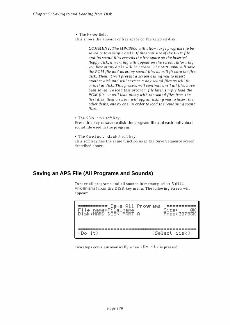
Page 170
Chapter 9: Saving to and Loading from Disk
• The Free field:This shows the amount of free space on the selected disk.
COMMENT: The MPC3000 will allow large programs to besaved onto multiple disks. If the total size of the PGM fileand its sound files exceeds the free space on the insertedfloppy disk, a warning will appear on the screen, informingyou how many disks will be needed. The MPC3000 will savethe PGM file and as many sound files as will fit onto the firstdisk. Then, it will present a screen asking you to insertanother disk and will save as many sound files as will fitonto that disk. This process will continue until all files havebeen saved. To load this program file later, simply load thePGM file—it will load along with the sound files from thefirst disk, then a screen will appear asking you to insert theother disks, one by one, in order to load the remaining soundfiles.
• The <Do it> soft key:Press this key to save to disk the program file and each individualsound file used in the program.
• The <Select disk> soft key:This soft key has the same function as in the Save Sequence screendescribed above.
Saving an APS File (All Programs and Sounds)
To save all programs and all sounds in memory, select 5 (Allprograms) from the DISK key menu. The following screen willappear:
========== Save All Programs ==========File name:File_name Size: 0KDisk:HARD DISK PART A Free:30793K
========================================<Do it> <Select disk>
Two steps occur automatically when <Do it> is pressed:
Page 171
Chapter 9: Saving to and Loading from Disk
1. The All Programs and Sounds file (APS), which contains the datafor all 24 programs and the names of all sounds in memory (butnot the sound data itself), is saved.
2. Each sound in memory (even sounds not currently assigned to aprogram) is individually saved as a sound file. If a sound file onthe disk has the same name as the sound being saved, the newsound won’t be saved.
The fields and soft keys are:
• The File name field:Enter the name for the file in this field. The name can be changed inthe same way as the Sequence Name field in the Play/Record screen.The file’s extension will be APS.
• The Disk field:This field has the same function as in the Save Sequence screendescribed above.
• The Size field:This field shows the combined size of the APS file and all individualsound files to be saved. (APS files require 48K.) Since sound fileswith the same name as those already on disk won’t be saved, it ispossible that not as much free space will be needed as is indicated inthis field.
• The Free field:This shows the amount of free space on the selected disk.
COMMENT: The MPC3000 will allow large APS files to besaved onto multiple disks. If the total size of the APS file andits sound files exceeds the free space on the inserted floppydisk, a warning will appear on the screen, informing youhow many disks will be needed. The MPC3000 will save theAPS file and as many sound files as will fit onto the firstdisk. Then, it will present a screen asking you to insertanother disk and will save as many sound files as will fitonto that disk. This process will continue until all files havebeen saved. To load this APS file later, simply load the APSfile from the first disk—it will load along with the sound filesfrom the first disk, then a screen will appear asking you toinsert the other disks, one by one, in order to load the remain-ing sound files.
• The <Do it> soft key:Press this key to save to disk the APS file and each individual soundfile currently in memory.
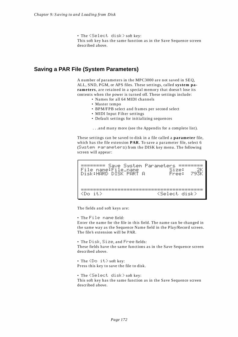
Page 172
Chapter 9: Saving to and Loading from Disk
• The <Select disk> soft key:This soft key has the same function as in the Save Sequence screendescribed above.
Saving a PAR File (System Parameters)
A number of parameters in the MPC3000 are not saved in SEQ,ALL, SND, PGM, or APS files. These settings, called system pa-rameters, are retained in a special memory that doesn’t lose itscontents when the power is turned off. These settings include:
• Names for all 64 MIDI channels• Master tempo• BPM/FPB select and frames per second select• MIDI Input Filter settings• Default settings for initializing sequences
. . .and many more (see the Appendix for a complete list).
These settings can be saved to disk in a file called a parameter file,which has the file extension PAR. To save a parameter file, select 6(System parameters) from the DISK key menu. The followingscreen will appear:
======== Save System Parameters ========File name:File_name Size: 2KDisk:HARD DISK PART A Free: 793K
========================================<Do it> <Select disk>
The fields and soft keys are:
• The File name field:Enter the name for the file in this field. The name can be changed inthe same way as the Sequence Name field in the Play/Record screen.The file’s extension will be PAR.
• The Disk, Size, and Free fields:These fields have the same functions as in the Save Sequence screendescribed above.
• The <Do it> soft key:Press this key to save the file to disk.
• The <Select disk> soft key:This soft key has the same function as in the Save Sequence screendescribed above.
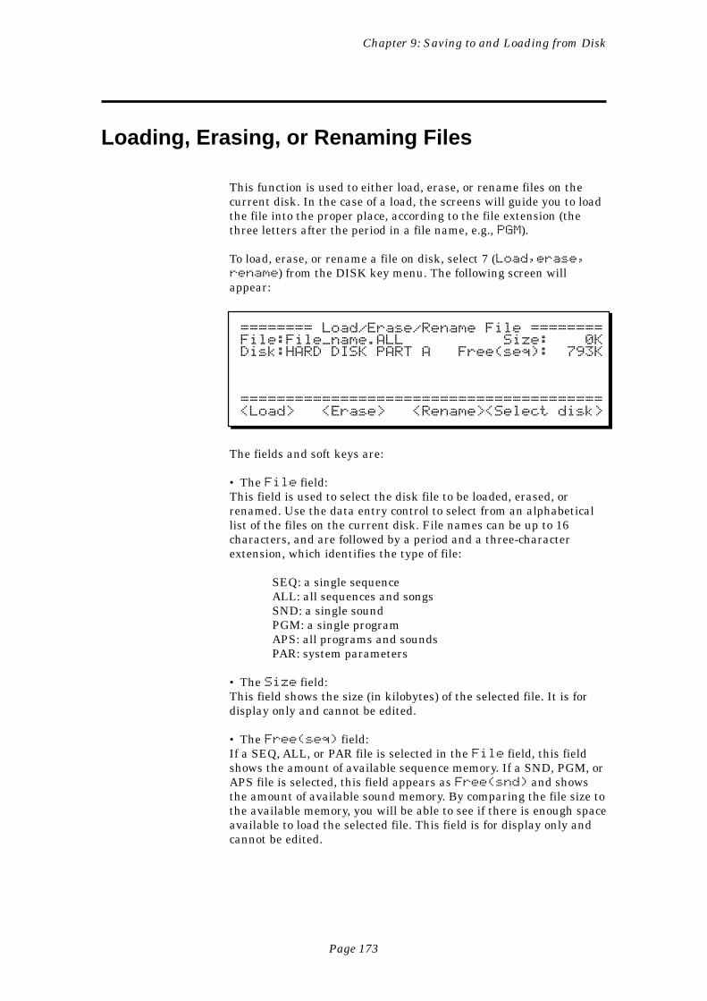
Page 173
Chapter 9: Saving to and Loading from Disk
Loading, Erasing, or Renaming Files
This function is used to either load, erase, or rename files on thecurrent disk. In the case of a load, the screens will guide you to loadthe file into the proper place, according to the file extension (thethree letters after the period in a file name, e.g., PGM).
To load, erase, or rename a file on disk, select 7 (Load,erase,rename) from the DISK key menu. The following screen willappear:
======== Load/Erase/Rename File ========File:File_name.ALL Size: 0KDisk:HARD DISK PART A Free(seq): 793K
========================================<Load> <Erase> <Rename><Select disk>
The fields and soft keys are:
• The File field:This field is used to select the disk file to be loaded, erased, orrenamed. Use the data entry control to select from an alphabeticallist of the files on the current disk. File names can be up to 16characters, and are followed by a period and a three-characterextension, which identifies the type of file:
SEQ: a single sequenceALL: all sequences and songsSND: a single soundPGM: a single programAPS: all programs and soundsPAR: system parameters
• The Size field:This field shows the size (in kilobytes) of the selected file. It is fordisplay only and cannot be edited.
• The Free(seq) field:If a SEQ, ALL, or PAR file is selected in the File field, this fieldshows the amount of available sequence memory. If a SND, PGM, orAPS file is selected, this field appears as Free(snd) and showsthe amount of available sound memory. By comparing the file size tothe available memory, you will be able to see if there is enough spaceavailable to load the selected file. This field is for display only andcannot be edited.
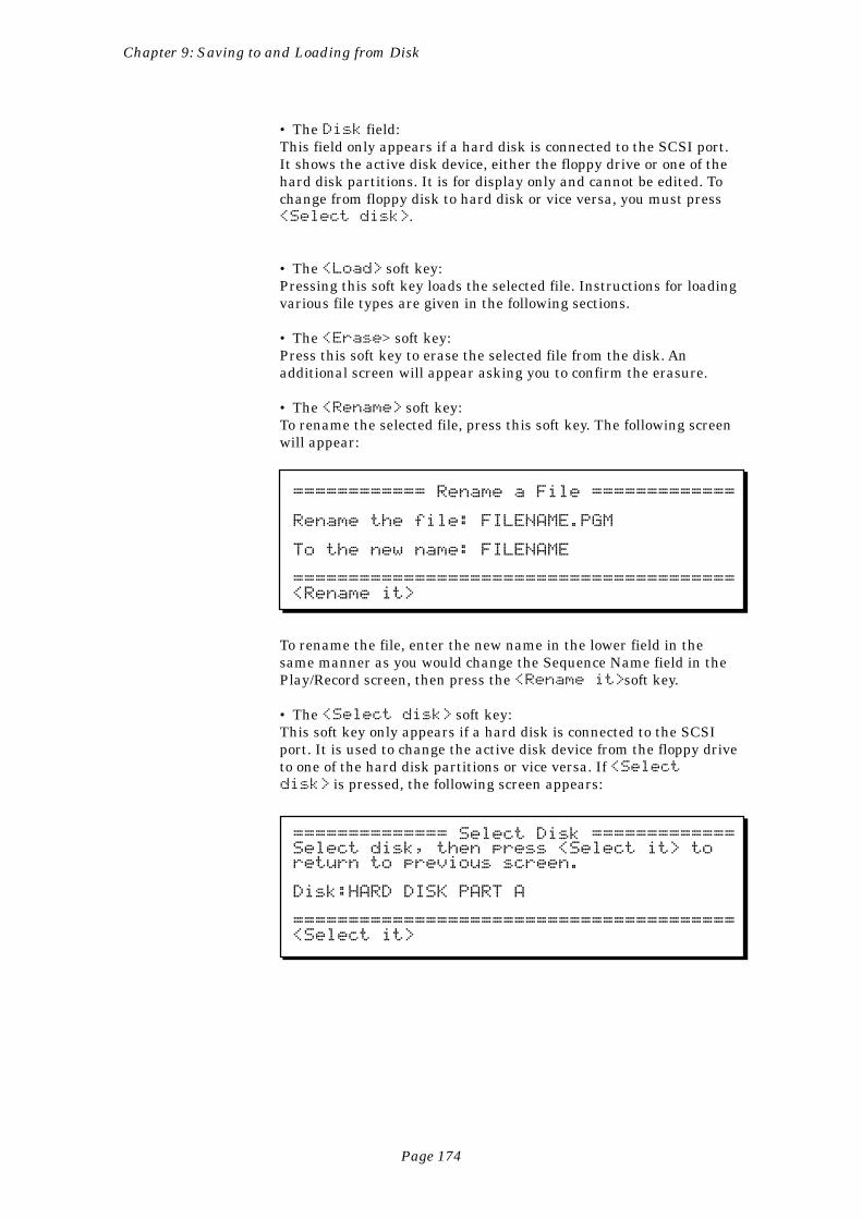
Page 174
Chapter 9: Saving to and Loading from Disk
• The Disk field:This field only appears if a hard disk is connected to the SCSI port.It shows the active disk device, either the floppy drive or one of thehard disk partitions. It is for display only and cannot be edited. Tochange from floppy disk to hard disk or vice versa, you must press<Select disk>.
• The <Load> soft key:Pressing this soft key loads the selected file. Instructions for loadingvarious file types are given in the following sections.
• The <Erase> soft key:Press this soft key to erase the selected file from the disk. Anadditional screen will appear asking you to confirm the erasure.
• The <Rename> soft key:To rename the selected file, press this soft key. The following screenwill appear:
============ Rename a File =============
Rename the file: FILENAME.PGM
To the new name: FILENAME
========================================<Rename it>
To rename the file, enter the new name in the lower field in thesame manner as you would change the Sequence Name field in thePlay/Record screen, then press the <Rename it>soft key.
• The <Select disk> soft key:This soft key only appears if a hard disk is connected to the SCSIport. It is used to change the active disk device from the floppy driveto one of the hard disk partitions or vice versa. If <Selectdisk> is pressed, the following screen appears:
============== Select Disk =============Select disk, then press <Select it> toreturn to previous screen.
Disk:HARD DISK PART A
========================================<Select it>
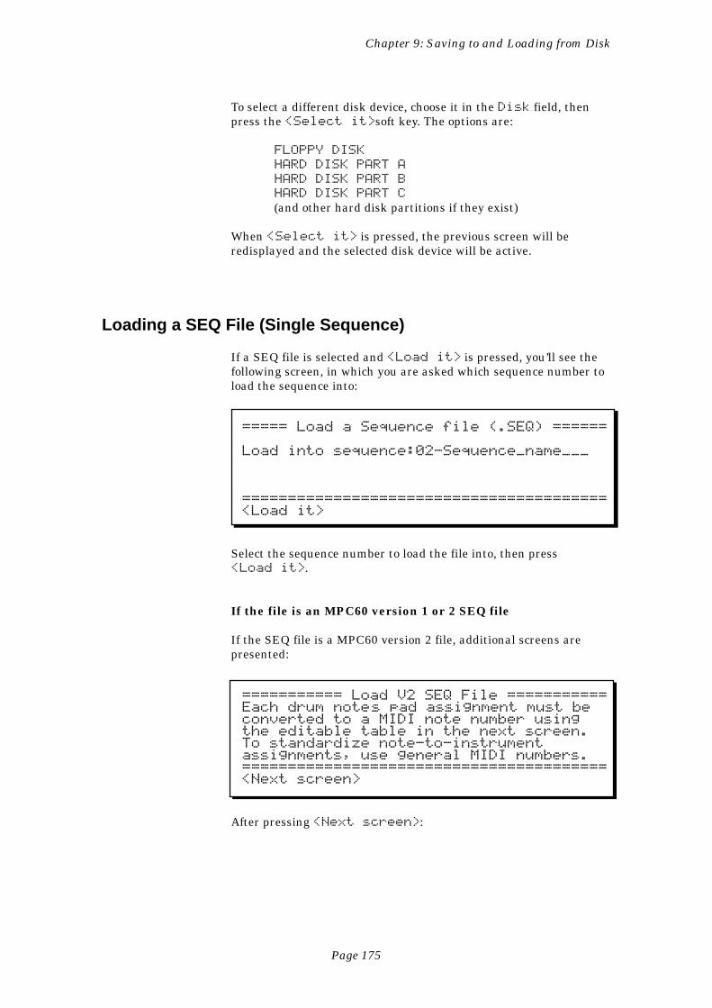
Page 175
Chapter 9: Saving to and Loading from Disk
To select a different disk device, choose it in the Disk field, thenpress the <Select it>soft key. The options are:
FLOPPY DISK
HARD DISK PART A
HARD DISK PART B
HARD DISK PART C
(and other hard disk partitions if they exist)
When <Select it> is pressed, the previous screen will beredisplayed and the selected disk device will be active.
Loading a SEQ File (Single Sequence)
If a SEQ file is selected and <Load it> is pressed, you’ll see thefollowing screen, in which you are asked which sequence number toload the sequence into:
===== Load a Sequence file (.SEQ) ======
Load into sequence:02-Sequence_name___
========================================<Load it>
Select the sequence number to load the file into, then press<Load it>.
If the file is an MPC60 version 1 or 2 SEQ file
If the SEQ file is a MPC60 version 2 file, additional screens arepresented:
=========== Load V2 SEQ File ===========Each drum noteÕs pad assignment must beconverted to a MIDI note number usingthe editable table in the next screen.To standardize note-to-instrumentassignments, use general MIDI numbers.========================================<Next screen>
After pressing <Next screen>:
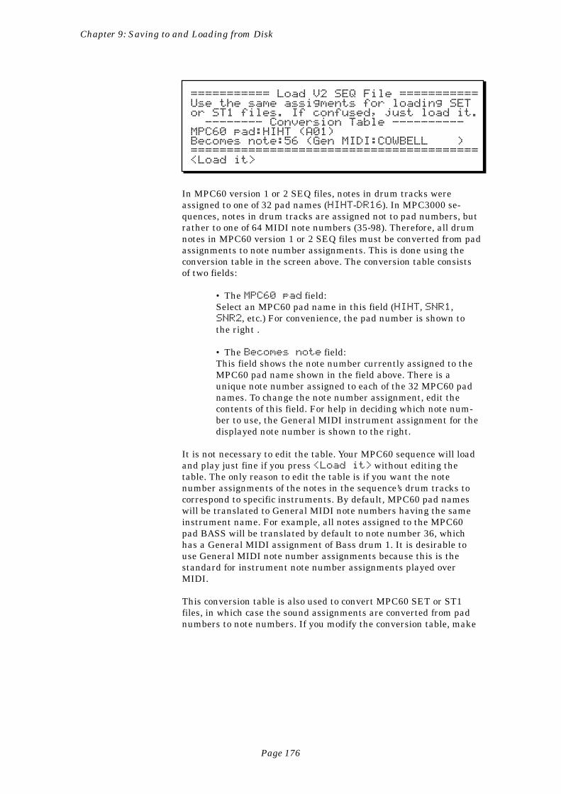
Page 176
Chapter 9: Saving to and Loading from Disk
=========== Load V2 SEQ File ===========Use the same assigments for loading SETor ST1 files. If confused, just load it. -------- Conversion Table ----------MPC60 pad:HIHT (A01)Becomes note:56 (Gen MIDI:COWBELL )========================================<Load it>
In MPC60 version 1 or 2 SEQ files, notes in drum tracks wereassigned to one of 32 pad names (HIHT-DR16). In MPC3000 se-quences, notes in drum tracks are assigned not to pad numbers, butrather to one of 64 MIDI note numbers (35-98). Therefore, all drumnotes in MPC60 version 1 or 2 SEQ files must be converted from padassignments to note number assignments. This is done using theconversion table in the screen above. The conversion table consistsof two fields:
• The MPC60 pad field:Select an MPC60 pad name in this field (HIHT, SNR1,SNR2, etc.) For convenience, the pad number is shown tothe right .
• The Becomes note field:This field shows the note number currently assigned to theMPC60 pad name shown in the field above. There is aunique note number assigned to each of the 32 MPC60 padnames. To change the note number assignment, edit thecontents of this field. For help in deciding which note num-ber to use, the General MIDI instrument assignment for thedisplayed note number is shown to the right.
It is not necessary to edit the table. Your MPC60 sequence will loadand play just fine if you press <Load it> without editing thetable. The only reason to edit the table is if you want the notenumber assignments of the notes in the sequence’s drum tracks tocorrespond to specific instruments. By default, MPC60 pad nameswill be translated to General MIDI note numbers having the sameinstrument name. For example, all notes assigned to the MPC60pad BASS will be translated by default to note number 36, whichhas a General MIDI assignment of Bass drum 1. It is desirable touse General MIDI note number assignments because this is thestandard for instrument note number assignments played overMIDI.
This conversion table is also used to convert MPC60 SET or ST1files, in which case the sound assignments are converted from padnumbers to note numbers. If you modify the conversion table, make
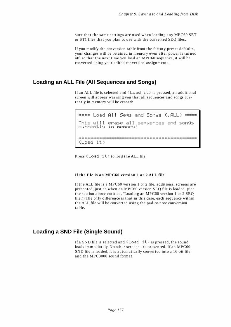
Page 177
Chapter 9: Saving to and Loading from Disk
sure that the same settings are used when loading any MPC60 SETor ST1 files that you plan to use with the converted SEQ files.
If you modify the conversion table from the factory-preset defaults,your changes will be retained in memory even after power is turnedoff, so that the next time you load an MPC60 sequence, it will beconverted using your edited conversion assignments.
Loading an ALL File (All Sequences and Songs)
If an ALL file is selected and <Load it> is pressed, an additionalscreen will appear warning you that all sequences and songs cur-rently in memory will be erased:
==== Load All Seqs and Songs (.ALL) ====
This will erase all sequences and songscurrently in memory!
========================================<Load it>
Press <Load it> to load the ALL file.
If the file is an MPC60 version 1 or 2 ALL file
If the ALL file is a MPC60 version 1 or 2 file, additional screens arepresented, just as when an MPC60 version SEQ file is loaded. (Seethe section above entitled, “Loading an MPC60 version 1 or 2 SEQfile.”) The only difference is that in this case, each sequence withinthe ALL file will be converted using the pad-to-note conversiontable.
Loading a SND File (Single Sound)
If a SND file is selected and <Load it> is pressed, the soundloads immediately. No other screens are presented. If an MPC60SND file is loaded, it is automatically converted into a 16-bit fileand the MPC3000 sound format.
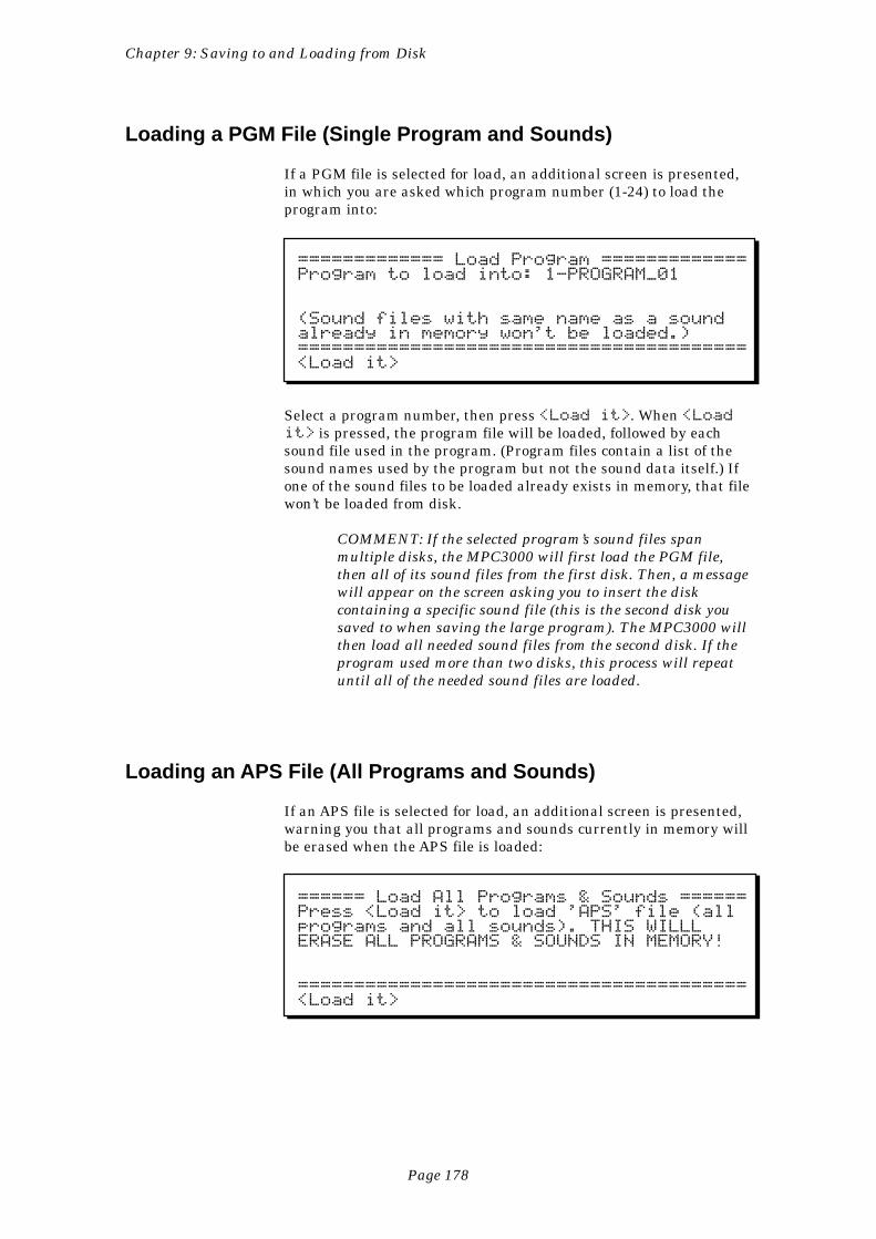
Page 178
Chapter 9: Saving to and Loading from Disk
Loading a PGM File (Single Program and Sounds)
If a PGM file is selected for load, an additional screen is presented,in which you are asked which program number (1-24) to load theprogram into:
============= Load Program =============Program to load into: 1-PROGRAM_01
(Sound files with same name as a soundalready in memory won't be loaded.)========================================<Load it>
Select a program number, then press <Load it>. When <Loadit> is pressed, the program file will be loaded, followed by eachsound file used in the program. (Program files contain a list of thesound names used by the program but not the sound data itself.) Ifone of the sound files to be loaded already exists in memory, that filewon’t be loaded from disk.
COMMENT: If the selected program’s sound files spanmultiple disks, the MPC3000 will first load the PGM file,then all of its sound files from the first disk. Then, a messagewill appear on the screen asking you to insert the diskcontaining a specific sound file (this is the second disk yousaved to when saving the large program). The MPC3000 willthen load all needed sound files from the second disk. If theprogram used more than two disks, this process will repeatuntil all of the needed sound files are loaded.
Loading an APS File (All Programs and Sounds)
If an APS file is selected for load, an additional screen is presented,warning you that all programs and sounds currently in memory willbe erased when the APS file is loaded:
====== Load All Programs & Sounds ======Press <Load it> to load 'APS' file (allprograms and all sounds). THIS WILLLERASE ALL PROGRAMS & SOUNDS IN MEMORY!
========================================<Load it>
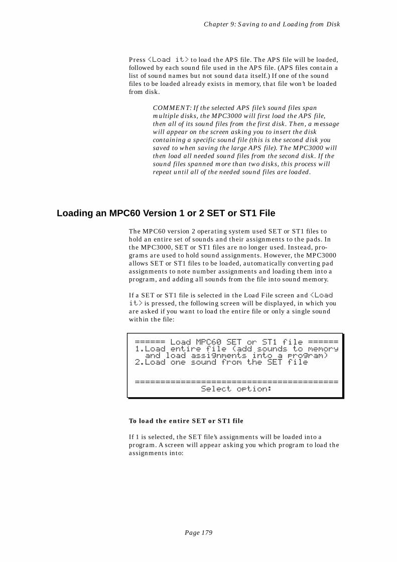
Page 179
Chapter 9: Saving to and Loading from Disk
Press <Load it> to load the APS file. The APS file will be loaded,followed by each sound file used in the APS file. (APS files contain alist of sound names but not sound data itself.) If one of the soundfiles to be loaded already exists in memory, that file won’t be loadedfrom disk.
COMMENT: If the selected APS file’s sound files spanmultiple disks, the MPC3000 will first load the APS file,then all of its sound files from the first disk. Then, a messagewill appear on the screen asking you to insert the diskcontaining a specific sound file (this is the second disk yousaved to when saving the large APS file). The MPC3000 willthen load all needed sound files from the second disk. If thesound files spanned more than two disks, this process willrepeat until all of the needed sound files are loaded.
Loading an MPC60 Version 1 or 2 SET or ST1 File
The MPC60 version 2 operating system used SET or ST1 files tohold an entire set of sounds and their assignments to the pads. Inthe MPC3000, SET or ST1 files are no longer used. Instead, pro-grams are used to hold sound assignments. However, the MPC3000allows SET or ST1 files to be loaded, automatically converting padassignments to note number assignments and loading them into aprogram, and adding all sounds from the file into sound memory.
If a SET or ST1 file is selected in the Load File screen and <Loadit> is pressed, the following screen will be displayed, in which youare asked if you want to load the entire file or only a single soundwithin the file:
====== Load MPC60 SET or ST1 file ======1.Load entire file (add sounds to memory and load assignments into a program)2.Load one sound from the SET file
======================================== Select option:
To load the entire SET or ST1 file
If 1 is selected, the SET file’s assignments will be loaded into aprogram. A screen will appear asking you which program to load theassignments into:
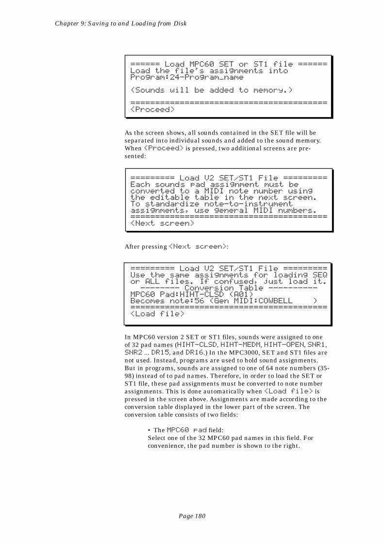
Page 180
Chapter 9: Saving to and Loading from Disk
====== Load MPC60 SET or ST1 file ======Load the file's assignments intoProgram:24-Program_name
(Sounds will be added to memory.)
========================================<Proceed>
As the screen shows, all sounds contained in the SET file will beseparated into individual sounds and added to the sound memory.When <Proceed> is pressed, two additional screens are pre-sented:
========= Load V2 SET/ST1 File =========Each soundÕs pad assignment must beconverted to a MIDI note number usingthe editable table in the next screen.To standardize note-to-instrumentassignments, use general MIDI numbers.========================================<Next screen>
After pressing <Next screen>:
========= Load V2 SET/ST1 File =========Use the same assignments for loading SEQor ALL files. If confused, just load it. -------- Conversion Table ----------MPC60 Pad:HIHT-CLSD (A01)Becomes note:56 (Gen MIDI:COWBELL )========================================<Load file>
In MPC60 version 2 SET or ST1 files, sounds were assigned to oneof 32 pad names (HIHT-CLSD, HIHT-MEDM, HIHT-OPEN, SNR1,SNR2 ... DR15, and DR16.) In the MPC3000, SET and ST1 files arenot used. Instead, programs are used to hold sound assignments.But in programs, sounds are assigned to one of 64 note numbers (35-98) instead of to pad names. Therefore, in order to load the SET orST1 file, these pad assignments must be converted to note numberassignments. This is done automatically when <Load file> ispressed in the screen above. Assignments are made according to theconversion table displayed in the lower part of the screen. Theconversion table consists of two fields:
• The MPC60 pad field:Select one of the 32 MPC60 pad names in this field. Forconvenience, the pad number is shown to the right.
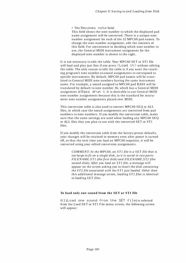
Page 181
Chapter 9: Saving to and Loading from Disk
• The Becomes note field:This field shows the note number to which the displayed padname assignment will be converted. There is a unique notenumber assignment for each of the 32 MPC60 pad names. Tochange the note number assignment, edit the contents ofthis field. For convenience in deciding which note number touse, the General MIDI instrument assignment for thedisplayed note number is shown to the right.
It is not necessary to edit the table. Your MPC60 SET or ST1 filewill load and play just fine if you press <Load it> without editingthe table. The only reason to edit the table is if you want the result-ing program’s note number-to-sound assignments to correspond tospecific instruments. By default, MPC60 pad names will be trans-lated to General MIDI note numbers having the same instrumentname. For example, a sound assigned to MPC60 pad BASS will betranslated by default to note number 36, which has a General MIDIassignment of Bass drum 1. It is desirable to use General MIDInote number assignments because this is the standard for instru-ment note number assignments played over MIDI.
This conversion table is also used to convert MPC60 SEQ or ALLfiles, in which case the sound assignments are converted from padnumbers to note numbers. If you modify the conversion table, makesure that the same settings are used when loading any MPC60 SEQor ALL files that you plan to use with the converted SET or ST1files.
If you modify the conversion table from the factory-preset defaults,your changes will be retained in memory even after power is turnedoff, so that the next time you load an MPC60 sequence, it will beconverted using your edited conversion assignments.
COMMENT: In the MPC60, an ST1 file is a SET file that istoo large to fit on a single disk, so it is saved in two parts:FILENAME.ST1 (the first disk) and FILENAME.ST2 (thesecond disk). After you load an ST1 file, a message willappear on the screen asking you to insert the disk containingthe ST2 file associated with the ST1 just loaded. Other thanthis additional message screen, loading ST1 files is identicalto loading SET files.
To load only one sound from the SET or ST1 file
If 2 (Load one sound from the SET file) is selectedfrom the Load SET or ST1 File menu screen, the following screenwill appear:
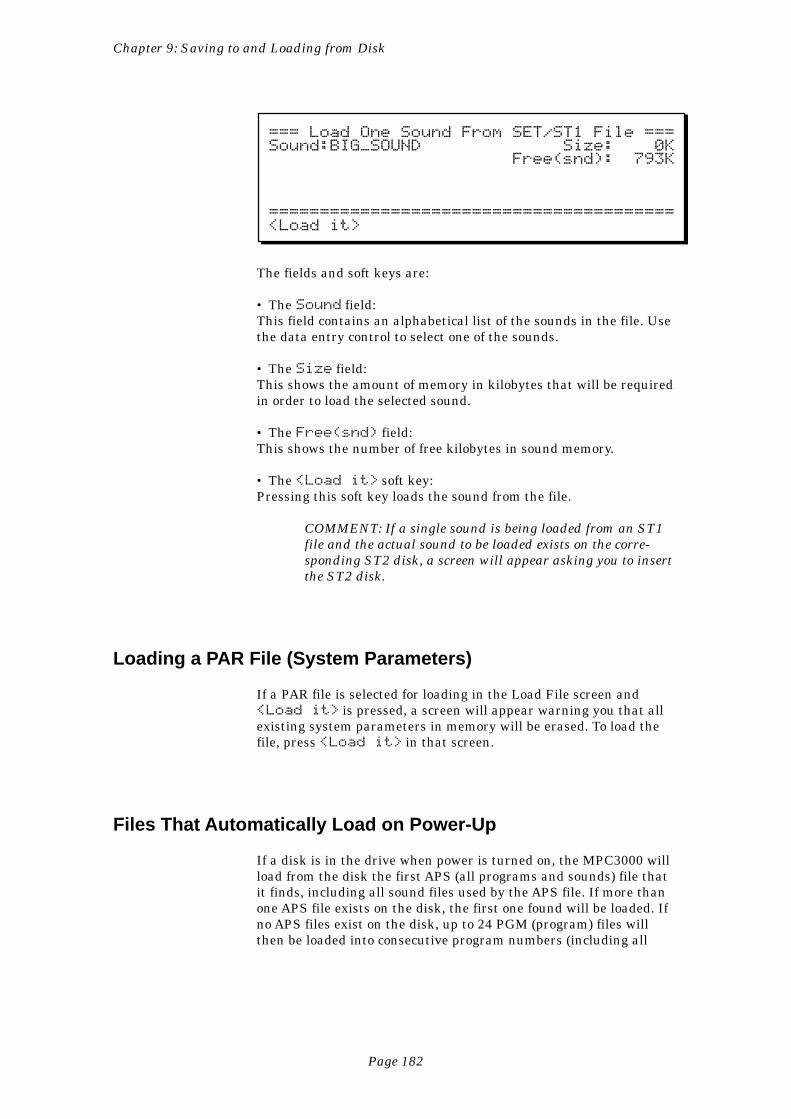
Page 182
Chapter 9: Saving to and Loading from Disk
=== Load One Sound From SET/ST1 File ===Sound:BIG_SOUND Size: 0K Free(snd): 793K
========================================<Load it>
The fields and soft keys are:
• The Sound field:This field contains an alphabetical list of the sounds in the file. Usethe data entry control to select one of the sounds.
• The Size field:This shows the amount of memory in kilobytes that will be requiredin order to load the selected sound.
• The Free(snd) field:This shows the number of free kilobytes in sound memory.
• The <Load it> soft key:Pressing this soft key loads the sound from the file.
COMMENT: If a single sound is being loaded from an ST1file and the actual sound to be loaded exists on the corre-sponding ST2 disk, a screen will appear asking you to insertthe ST2 disk.
Loading a PAR File (System Parameters)
If a PAR file is selected for loading in the Load File screen and<Load it> is pressed, a screen will appear warning you that allexisting system parameters in memory will be erased. To load thefile, press <Load it> in that screen.
Files That Automatically Load on Power-Up
If a disk is in the drive when power is turned on, the MPC3000 willload from the disk the first APS (all programs and sounds) file thatit finds, including all sound files used by the APS file. If more thanone APS file exists on the disk, the first one found will be loaded. Ifno APS files exist on the disk, up to 24 PGM (program) files willthen be loaded into consecutive program numbers (including all
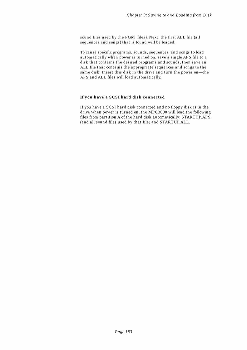
Page 183
Chapter 9: Saving to and Loading from Disk
sound files used by the PGM files). Next, the first ALL file (allsequences and songs) that is found will be loaded.
To cause specific programs, sounds, sequences, and songs to loadautomatically when power is turned on, save a single APS file to adisk that contains the desired programs and sounds, then save anALL file that contains the appropriate sequences and songs to thesame disk. Insert this disk in the drive and turn the power on—theAPS and ALL files will load automatically.
If you have a SCSI hard disk connected
If you have a SCSI hard disk connected and no floppy disk is in thedrive when power is turned on, the MPC3000 will load the followingfiles from partition A of the hard disk automatically: STARTUP.APS(and all sound files used by that file) and STARTUP.ALL.
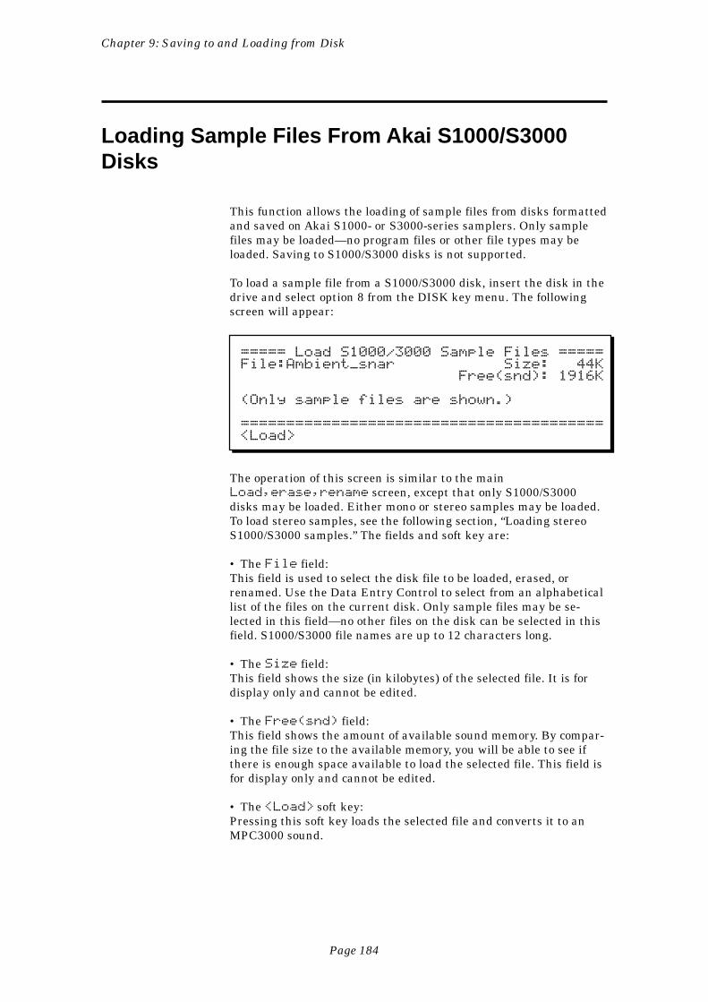
Page 184
Chapter 9: Saving to and Loading from Disk
Loading Sample Files From Akai S1000/S3000Disks
This function allows the loading of sample files from disks formattedand saved on Akai S1000- or S3000-series samplers. Only samplefiles may be loaded—no program files or other file types may beloaded. Saving to S1000/S3000 disks is not supported.
To load a sample file from a S1000/S3000 disk, insert the disk in thedrive and select option 8 from the DISK key menu. The followingscreen will appear:
===== Load S1000/3000 Sample Files =====File:Ambient_snar Size: 44K Free(snd): 1916K
(Only sample files are shown.)
========================================<Load>
The operation of this screen is similar to the mainLoad,erase,rename screen, except that only S1000/S3000disks may be loaded. Either mono or stereo samples may be loaded.To load stereo samples, see the following section, “Loading stereoS1000/S3000 samples.” The fields and soft key are:
• The File field:This field is used to select the disk file to be loaded, erased, orrenamed. Use the Data Entry Control to select from an alphabeticallist of the files on the current disk. Only sample files may be se-lected in this field—no other files on the disk can be selected in thisfield. S1000/S3000 file names are up to 12 characters long.
• The Size field:This field shows the size (in kilobytes) of the selected file. It is fordisplay only and cannot be edited.
• The Free(snd) field:This field shows the amount of available sound memory. By compar-ing the file size to the available memory, you will be able to see ifthere is enough space available to load the selected file. This field isfor display only and cannot be edited.
• The <Load> soft key:Pressing this soft key loads the selected file and converts it to anMPC3000 sound.
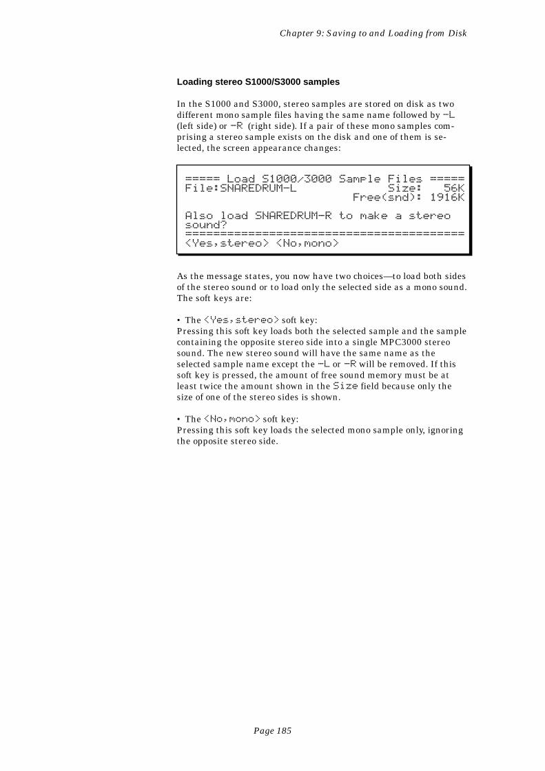
Page 185
Chapter 9: Saving to and Loading from Disk
Loading stereo S1000/S3000 samples
In the S1000 and S3000, stereo samples are stored on disk as twodifferent mono sample files having the same name followed by -L(left side) or -R (right side). If a pair of these mono samples com-prising a stereo sample exists on the disk and one of them is se-lected, the screen appearance changes:
===== Load S1000/3000 Sample Files =====File:SNAREDRUM-L Size: 56K Free(snd): 1916K
Also load SNAREDRUM-R to make a stereosound?========================================<Yes,stereo> <No,mono>
As the message states, you now have two choices—to load both sidesof the stereo sound or to load only the selected side as a mono sound.The soft keys are:
• The <Yes,stereo> soft key:Pressing this soft key loads both the selected sample and the samplecontaining the opposite stereo side into a single MPC3000 stereosound. The new stereo sound will have the same name as theselected sample name except the -L or -R will be removed. If thissoft key is pressed, the amount of free sound memory must be atleast twice the amount shown in the Size field because only thesize of one of the stereo sides is shown.
• The <No,mono> soft key:Pressing this soft key loads the selected mono sample only, ignoringthe opposite stereo side.
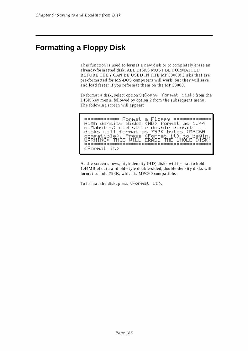
Page 186
Chapter 9: Saving to and Loading from Disk
Formatting a Floppy Disk
This function is used to format a new disk or to completely erase analready-formatted disk. ALL DISKS MUST BE FORMATTEDBEFORE THEY CAN BE USED IN THE MPC3000! Disks that arepre-formatted for MS-DOS computers will work, but they will saveand load faster if you reformat them on the MPC3000.
To format a disk, select option 9 (Copy, format disk) from theDISK key menu, followed by option 2 from the subsequent menu.The following screen will appear:
=========== Format a Floppy ============High density disks (HD) format as 1.44megabytes; old style double densitydisks will format as 793K bytes (MPC60compatible). Press <Format it> to begin.WARNING: THIS WILL ERASE THE WHOLE DISK!========================================<Format it>
As the screen shows, high-density (HD) disks will format to hold1.44MB of data and old-style double-sided, double-density disks willformat to hold 793K, which is MPC60 compatible.
To format the disk, press <Format it>.
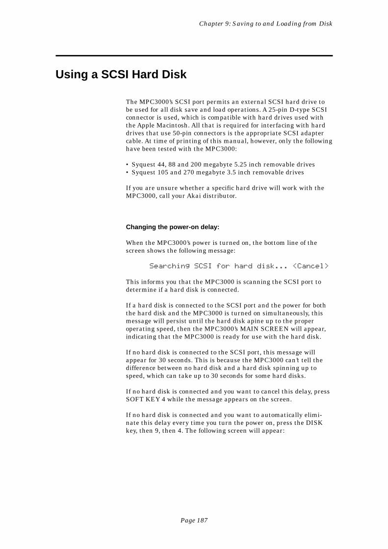
Page 187
Chapter 9: Saving to and Loading from Disk
Using a SCSI Hard Disk
The MPC3000’s SCSI port permits an external SCSI hard drive tobe used for all disk save and load operations. A 25-pin D-type SCSIconnector is used, which is compatible with hard drives used withthe Apple Macintosh. All that is required for interfacing with harddrives that use 50-pin connectors is the appropriate SCSI adaptercable. At time of printing of this manual, however, only the followinghave been tested with the MPC3000:
• Syquest 44, 88 and 200 megabyte 5.25 inch removable drives• Syquest 105 and 270 megabyte 3.5 inch removable drives
If you are unsure whether a specific hard drive will work with theMPC3000, call your Akai distributor.
Changing the power-on delay:
When the MPC3000’s power is turned on, the bottom line of thescreen shows the following message:
Searching SCSI for hard disk... <Cancel>
This informs you that the MPC3000 is scanning the SCSI port todetermine if a hard disk is connected.
If a hard disk is connected to the SCSI port and the power for boththe hard disk and the MPC3000 is turned on simultaneously, thismessage will persist until the hard disk apine up to the properoperating speed, then the MPC3000’s MAIN SCREEN will appear,indicating that the MPC3000 is ready for use with the hard disk.
If no hard disk is connected to the SCSI port, this message willappear for 30 seconds. This is because the MPC3000 can’t tell thedifference between no hard disk and a hard disk spinning up tospeed, which can take up to 30 seconds for some hard disks.
If no hard disk is connected and you want to cancel this delay, pressSOFT KEY 4 while the message appears on the screen.
If no hard disk is connected and you want to automatically elimi-nate this delay every time you turn the power on, press the DISKkey, then 9, then 4. The following screen will appear:
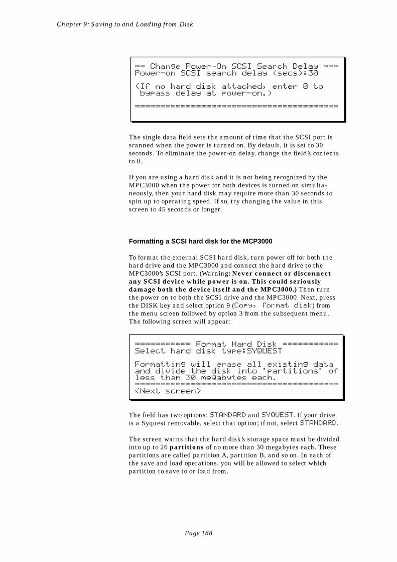
Page 188
Chapter 9: Saving to and Loading from Disk
== Change Power-On SCSI Search Delay ===Power-on SCSI search delay (secs):30
(If no hard disk attached, enter 0 to bypass delay at power-on.)
========================================
The single data field sets the amount of time that the SCSI port isscanned when the power is turned on. By default, it is set to 30seconds. To eliminate the power-on delay, change the field’s contentsto 0.
If you are using a hard disk and it is not being recognized by theMPC3000 when the power for both devices is turned on simulta-neously, then your hard disk may require more than 30 seconds tospin up to operating speed. If so, try changing the value in thisscreen to 45 seconds or longer.
Formatting a SCSI hard disk for the MCP3000
To format the external SCSI hard disk, turn power off for both thehard drive and the MPC3000 and connect the hard drive to theMPC3000’s SCSI port. (Warning: Never connect or disconnectany SCSI device while power is on. This could seriouslydamage both the device itself and the MPC3000.) Then turnthe power on to both the SCSI drive and the MPC3000. Next, pressthe DISK key and select option 9 (Copy, format disk) fromthe menu screen followed by option 3 from the subsequent menu.The following screen will appear:
=========== Format Hard Disk ===========Select hard disk type:SYQUEST
Formatting will erase all existing dataand divide the disk into 'partitions' ofless than 30 megabytes each.========================================<Next screen>
The field has two options: STANDARD and SYQUEST. If your driveis a Syquest removable, select that option; if not, select STANDARD.
The screen warns that the hard disk’s storage space must be dividedinto up to 26 partitions of no more than 30 megabytes each. Thesepartitions are called partition A, partition B, and so on. In each ofthe save and load operations, you will be allowed to select whichpartition to save to or load from.
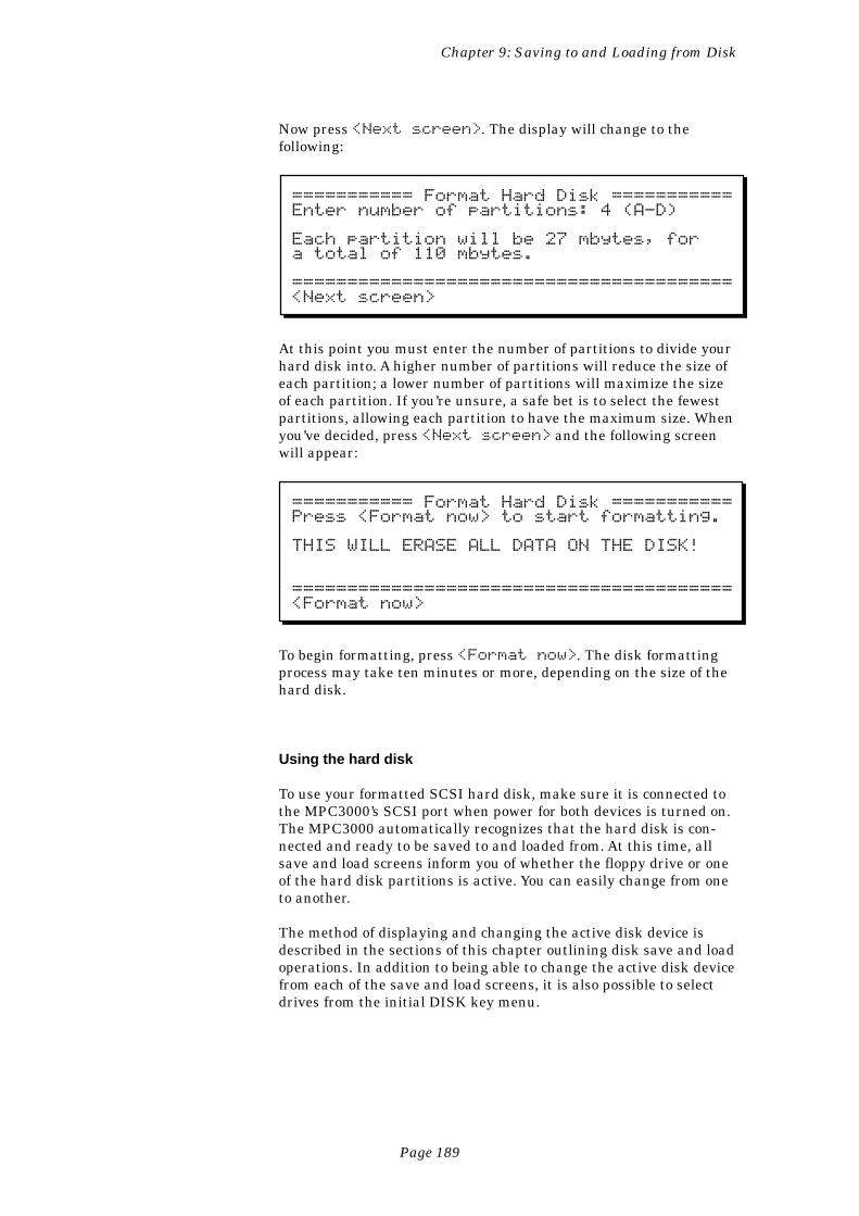
Page 189
Chapter 9: Saving to and Loading from Disk
Now press <Next screen>. The display will change to thefollowing:
=========== Format Hard Disk ===========Enter number of partitions: 4 (A-D)
Each partition will be 27 mbytes, fora total of 110 mbytes.
========================================<Next screen>
At this point you must enter the number of partitions to divide yourhard disk into. A higher number of partitions will reduce the size ofeach partition; a lower number of partitions will maximize the sizeof each partition. If you’re unsure, a safe bet is to select the fewestpartitions, allowing each partition to have the maximum size. Whenyou’ve decided, press <Next screen> and the following screenwill appear:
=========== Format Hard Disk ===========Press <Format now> to start formatting.
THIS WILL ERASE ALL DATA ON THE DISK!
========================================<Format now>
To begin formatting, press <Format now>. The disk formattingprocess may take ten minutes or more, depending on the size of thehard disk.
Using the hard disk
To use your formatted SCSI hard disk, make sure it is connected tothe MPC3000’s SCSI port when power for both devices is turned on.The MPC3000 automatically recognizes that the hard disk is con-nected and ready to be saved to and loaded from. At this time, allsave and load screens inform you of whether the floppy drive or oneof the hard disk partitions is active. You can easily change from oneto another.
The method of displaying and changing the active disk device isdescribed in the sections of this chapter outlining disk save and loadoperations. In addition to being able to change the active disk devicefrom each of the save and load screens, it is also possible to selectdrives from the initial DISK key menu.
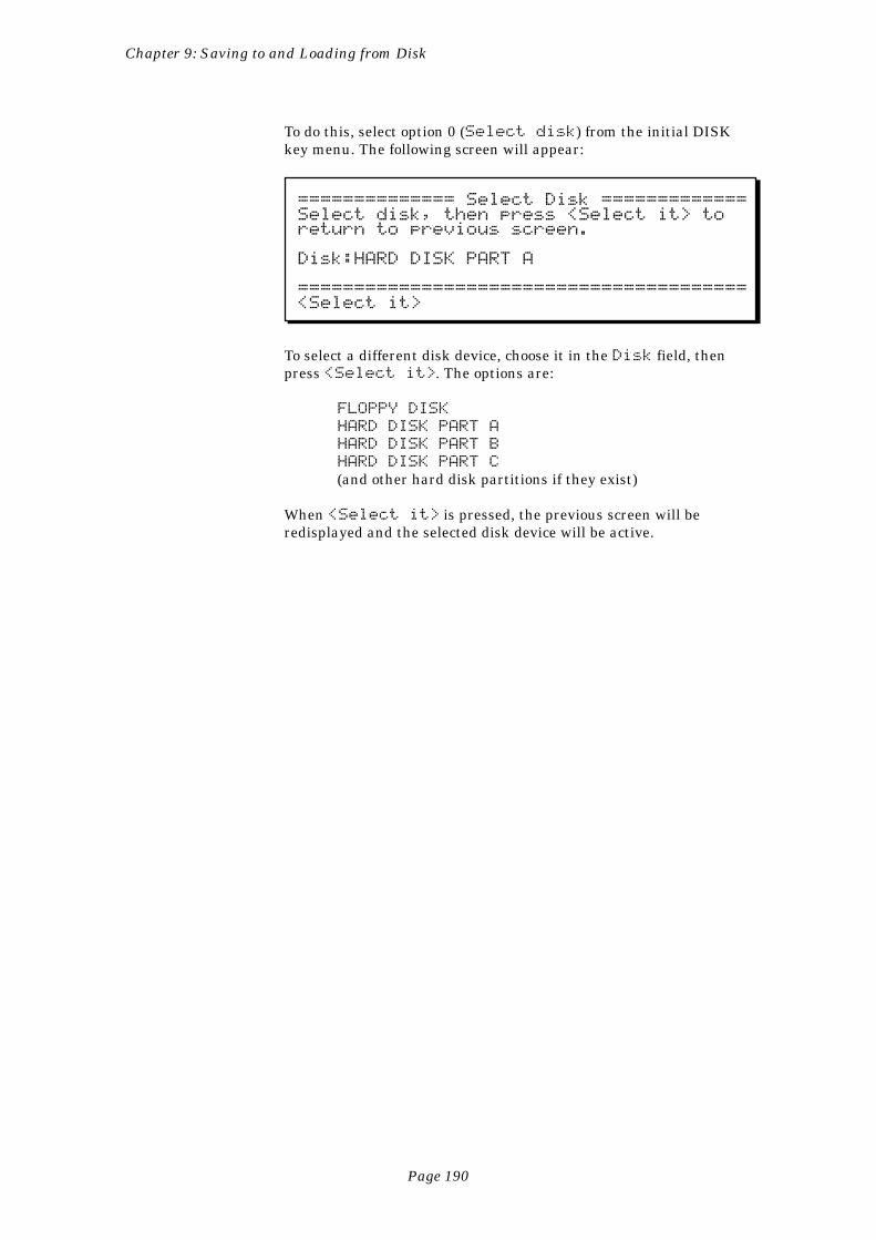
Page 190
Chapter 9: Saving to and Loading from Disk
To do this, select option 0 (Select disk) from the initial DISKkey menu. The following screen will appear:
============== Select Disk =============Select disk, then press <Select it> toreturn to previous screen.
Disk:HARD DISK PART A
========================================<Select it>
To select a different disk device, choose it in the Disk field, thenpress <Select it>. The options are:
FLOPPY DISK
HARD DISK PART A
HARD DISK PART B
HARD DISK PART C
(and other hard disk partitions if they exist)
When <Select it> is pressed, the previous screen will beredisplayed and the selected disk device will be active.
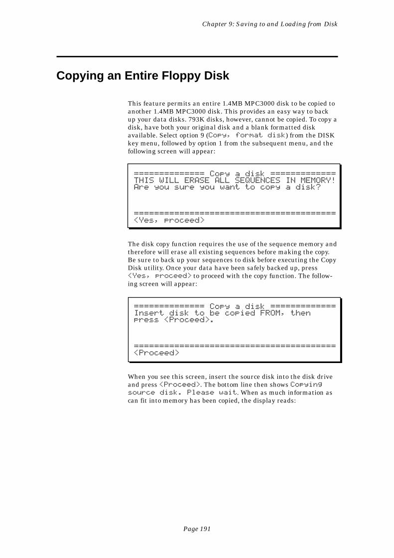
Page 191
Chapter 9: Saving to and Loading from Disk
Copying an Entire Floppy Disk
This feature permits an entire 1.4MB MPC3000 disk to be copied toanother 1.4MB MPC3000 disk. This provides an easy way to backup your data disks. 793K disks, however, cannot be copied. To copy adisk, have both your original disk and a blank formatted diskavailable. Select option 9 (Copy, format disk) from the DISKkey menu, followed by option 1 from the subsequent menu, and thefollowing screen will appear:
============== Copy a disk =============THIS WILL ERASE ALL SEQUENCES IN MEMORY!Are you sure you want to copy a disk?
========================================<Yes, proceed>
The disk copy function requires the use of the sequence memory andtherefore will erase all existing sequences before making the copy.Be sure to back up your sequences to disk before executing the CopyDisk utility. Once your data have been safely backed up, press<Yes, proceed> to proceed with the copy function. The follow-ing screen will appear:
============== Copy a disk =============Insert disk to be copied FROM, thenpress <Proceed>.
========================================<Proceed>
When you see this screen, insert the source disk into the disk driveand press <Proceed>. The bottom line then shows Copyingsource disk. Please wait. When as much information ascan fit into memory has been copied, the display reads:
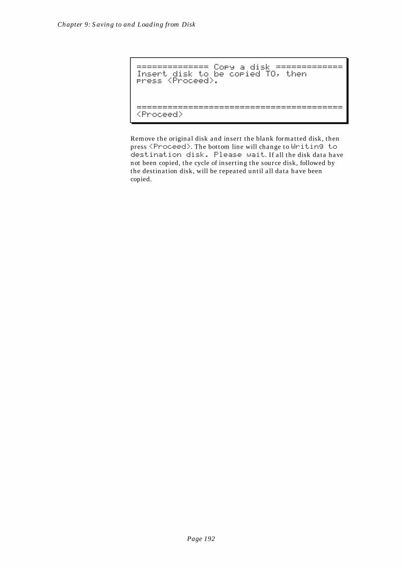
Page 192
Chapter 9: Saving to and Loading from Disk
============== Copy a disk =============Insert disk to be copied TO, thenpress <Proceed>.
========================================<Proceed>
Remove the original disk and insert the blank formatted disk, thenpress <Proceed>. The bottom line will change to Writing todestination disk. Please wait. If all the disk data havenot been copied, the cycle of inserting the source disk, followed bythe destination disk, will be repeated until all data have beencopied.
Page 193
Chapter 10: Syncing to Tape and Other Devices
Chapter 10:Syncing to Tape
and Other Devices
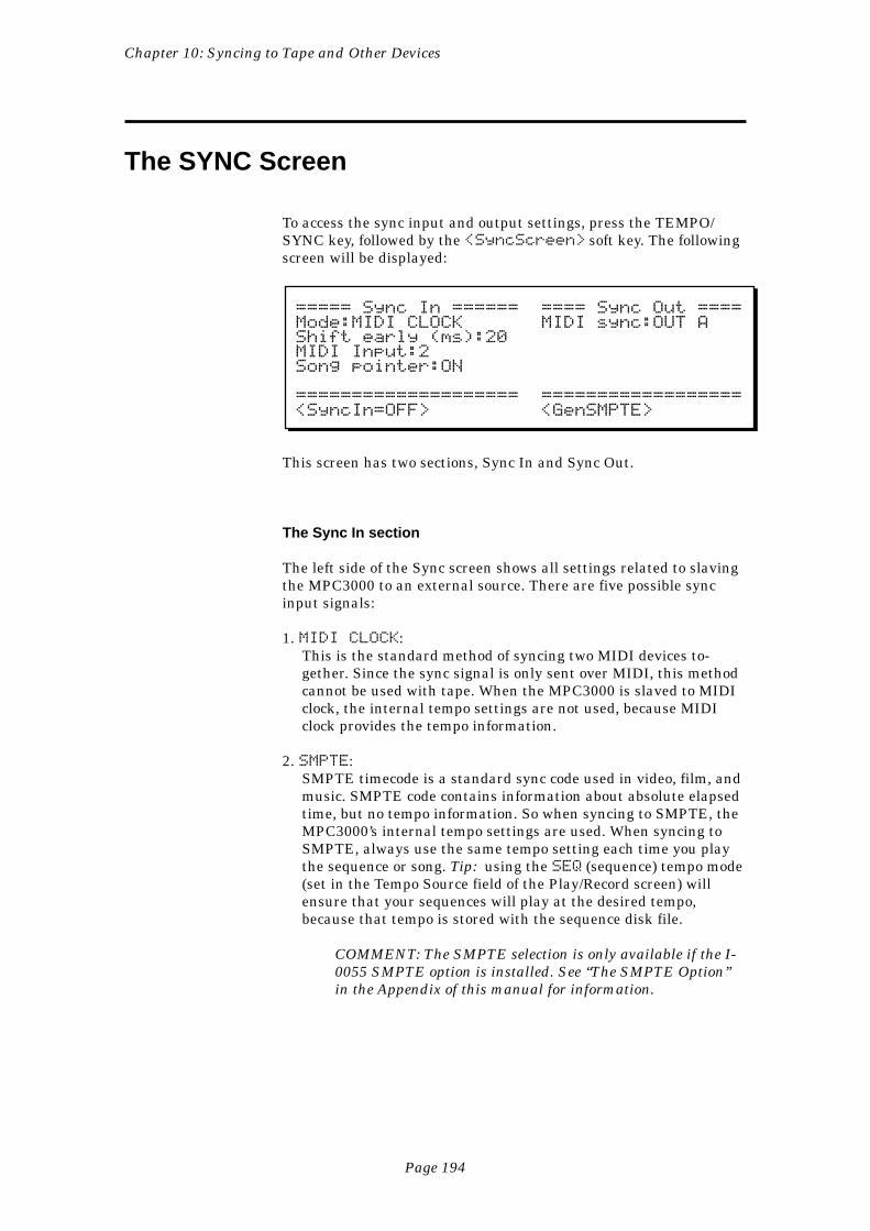
Page 194
Chapter 10: Syncing to Tape and Other Devices
The SYNC Screen
To access the sync input and output settings, press the TEMPO/SYNC key, followed by the <SyncScreen> soft key. The followingscreen will be displayed:
===== Sync In ====== ==== Sync Out ====Mode:MIDI CLOCK MIDI sync:OUT AShift early (ms):20MIDI Input:2Song pointer:ON
==================== ==================<SyncIn=OFF> <GenSMPTE>
This screen has two sections, Sync In and Sync Out.
The Sync In section
The left side of the Sync screen shows all settings related to slavingthe MPC3000 to an external source. There are five possible syncinput signals:
1. MIDI CLOCK:This is the standard method of syncing two MIDI devices to-gether. Since the sync signal is only sent over MIDI, this methodcannot be used with tape. When the MPC3000 is slaved to MIDIclock, the internal tempo settings are not used, because MIDIclock provides the tempo information.
2. SMPTE:SMPTE timecode is a standard sync code used in video, film, andmusic. SMPTE code contains information about absolute elapsedtime, but no tempo information. So when syncing to SMPTE, theMPC3000’s internal tempo settings are used. When syncing toSMPTE, always use the same tempo setting each time you playthe sequence or song. Tip: using the SEQ (sequence) tempo mode(set in the Tempo Source field of the Play/Record screen) willensure that your sequences will play at the desired tempo,because that tempo is stored with the sequence disk file.
COMMENT: The SMPTE selection is only available if the I-0055 SMPTE option is installed. See “The SMPTE Option”in the Appendix of this manual for information.
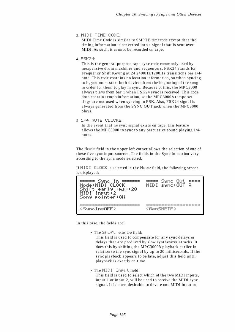
Page 195
Chapter 10: Syncing to Tape and Other Devices
3. MIDI TIME CODE:MIDI Time Code is similar to SMPTE timecode except that thetiming information is converted into a signal that is sent overMIDI. As such, it cannot be recorded on tape.
4. FSK24:This is the general-purpose tape sync code commonly used byinexpensive drum machines and sequencers. FSK24 stands forFrequency Shift Keying at 24 2400Hz/1200Hz transitions per 1/4-note. This code contains no location information, so when syncingto it, you must start both devices from the beginning of the songin order for them to play in sync. Because of this, the MPC3000always plays from bar 1 when FSK24 sync is received. This codedoes contain tempo information, so the MPC3000’s tempo set-tings are not used when syncing to FSK. Also, FSK24 signal isalways generated from the SYNC OUT jack when the MPC3000plays.
5. 1/4 NOTE CLICKS:In the event that no sync signal exists on tape, this featureallows the MPC3000 to sync to any percussive sound playing 1/4-notes.
The Mode field in the upper left corner allows the selection of one ofthese five sync input sources. The fields in the Sync In section varyaccording to the sync mode selected.
If MIDI CLOCK is selected in the Mode field, the following screenis displayed:
===== Sync In ====== ==== Sync Out ====Mode:MIDI CLOCK MIDI sync:OUT AShift early (ms):20MIDI Input:2Song pointer:ON
==================== ==================<SyncIn=OFF> <GenSMPTE>
In this case, the fields are:
• The Shift early field:This field is used to compensate for any sync delays ordelays that are produced by slow synthesizer attacks. Itdoes this by shifting the MPC3000’s playback earlier inrelation to the sync signal by up to 20 milliseconds. If thesync playback appears to be late, adjust this field untilplayback is exactly on time.
• The MIDI Input field:This field is used to select which of the two MIDI inputs,input 1 or input 2, will be used to receive the MIDI syncsignal. It is often desirable to devote one MIDI input to
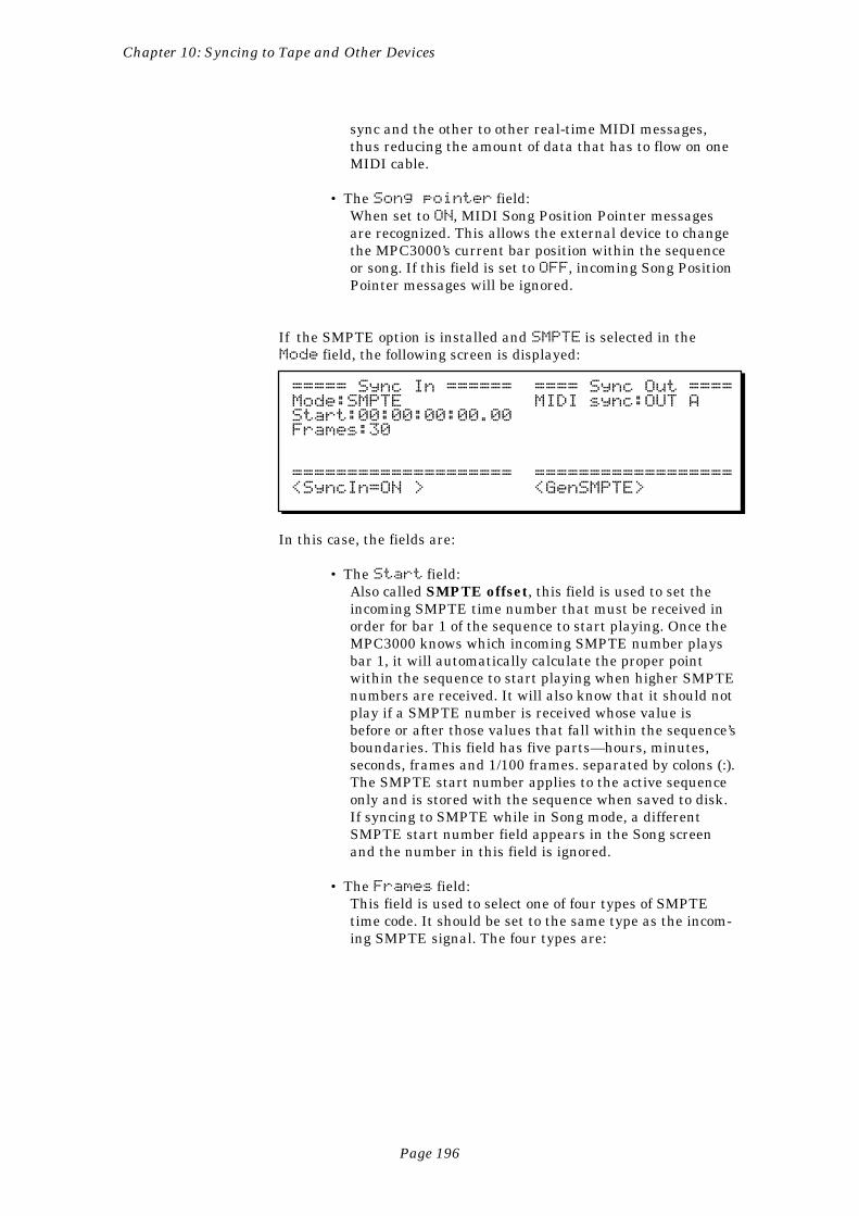
Page 196
Chapter 10: Syncing to Tape and Other Devices
sync and the other to other real-time MIDI messages,thus reducing the amount of data that has to flow on oneMIDI cable.
• The Song pointer field:When set to ON, MIDI Song Position Pointer messagesare recognized. This allows the external device to changethe MPC3000’s current bar position within the sequenceor song. If this field is set to OFF, incoming Song PositionPointer messages will be ignored.
If the SMPTE option is installed and SMPTE is selected in theMode field, the following screen is displayed:
===== Sync In ====== ==== Sync Out ====Mode:SMPTE MIDI sync:OUT AStart:00:00:00:00.00Frames:30
==================== ==================<SyncIn=ON > <GenSMPTE>
In this case, the fields are:
• The Start field:Also called SMPTE offset, this field is used to set theincoming SMPTE time number that must be received inorder for bar 1 of the sequence to start playing. Once theMPC3000 knows which incoming SMPTE number playsbar 1, it will automatically calculate the proper pointwithin the sequence to start playing when higher SMPTEnumbers are received. It will also know that it should notplay if a SMPTE number is received whose value isbefore or after those values that fall within the sequence’sboundaries. This field has five parts—hours, minutes,seconds, frames and 1/100 frames. separated by colons (:).The SMPTE start number applies to the active sequenceonly and is stored with the sequence when saved to disk.If syncing to SMPTE while in Song mode, a differentSMPTE start number field appears in the Song screenand the number in this field is ignored.
• The Frames field:This field is used to select one of four types of SMPTEtime code. It should be set to the same type as the incom-ing SMPTE signal. The four types are:
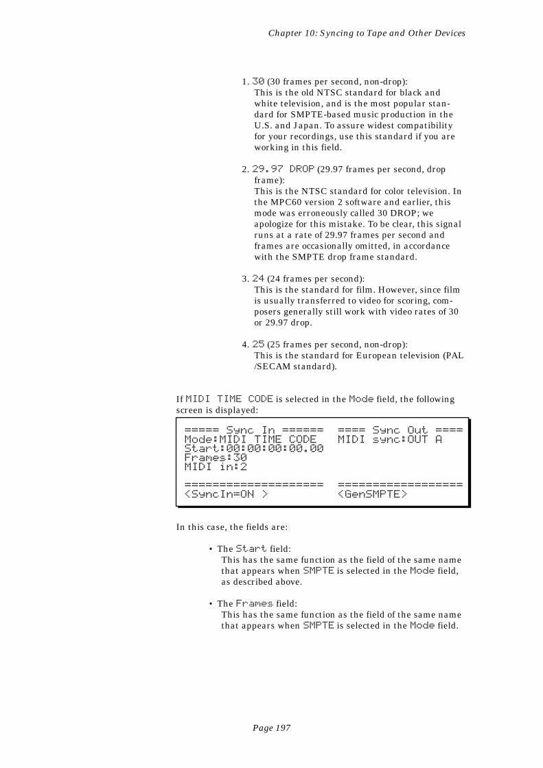
Page 197
Chapter 10: Syncing to Tape and Other Devices
1. 30 (30 frames per second, non-drop):This is the old NTSC standard for black andwhite television, and is the most popular stan-dard for SMPTE-based music production in theU.S. and Japan. To assure widest compatibilityfor your recordings, use this standard if you areworking in this field.
2. 29.97 DROP (29.97 frames per second, dropframe):This is the NTSC standard for color television. Inthe MPC60 version 2 software and earlier, thismode was erroneously called 30 DROP; weapologize for this mistake. To be clear, this signalruns at a rate of 29.97 frames per second andframes are occasionally omitted, in accordancewith the SMPTE drop frame standard.
3. 24 (24 frames per second):This is the standard for film. However, since filmis usually transferred to video for scoring, com-posers generally still work with video rates of 30or 29.97 drop.
4. 25 (25 frames per second, non-drop):This is the standard for European television (PAL/SECAM standard).
If MIDI TIME CODE is selected in the Mode field, the followingscreen is displayed:
===== Sync In ====== ==== Sync Out ====Mode:MIDI TIME CODE MIDI sync:OUT AStart:00:00:00:00.00Frames:30MIDI in:2
==================== ==================<SyncIn=ON > <GenSMPTE>
In this case, the fields are:
• The Start field:This has the same function as the field of the same namethat appears when SMPTE is selected in the Mode field,as described above.
• The Frames field:This has the same function as the field of the same namethat appears when SMPTE is selected in the Mode field.
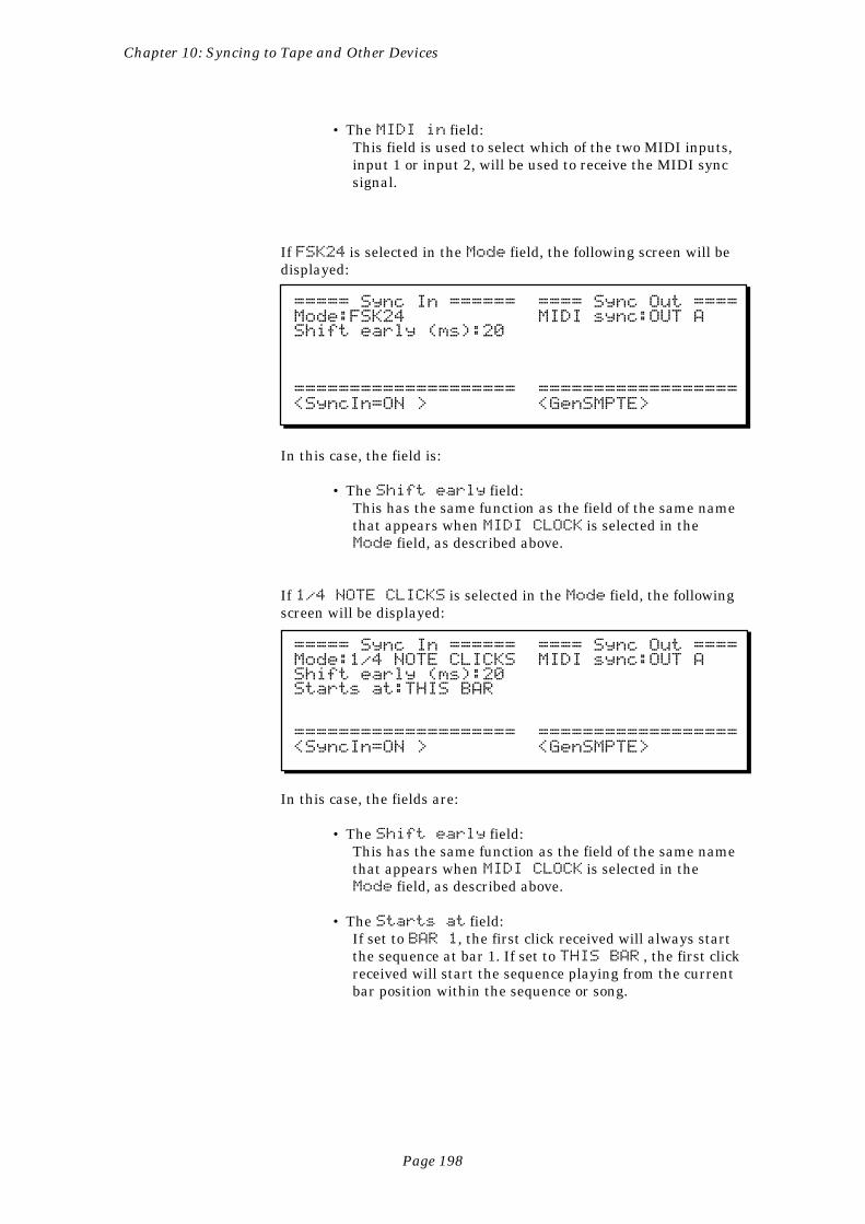
Page 198
Chapter 10: Syncing to Tape and Other Devices
• The MIDI in field:This field is used to select which of the two MIDI inputs,input 1 or input 2, will be used to receive the MIDI syncsignal.
If FSK24 is selected in the Mode field, the following screen will bedisplayed:
===== Sync In ====== ==== Sync Out ====Mode:FSK24 MIDI sync:OUT AShift early (ms):20
==================== ==================<SyncIn=ON > <GenSMPTE>
In this case, the field is:
• The Shift early field:This has the same function as the field of the same namethat appears when MIDI CLOCK is selected in theMode field, as described above.
If 1/4 NOTE CLICKS is selected in the Mode field, the followingscreen will be displayed:
===== Sync In ====== ==== Sync Out ====Mode:1/4 NOTE CLICKS MIDI sync:OUT AShift early (ms):20Starts at:THIS BAR
==================== ==================<SyncIn=ON > <GenSMPTE>
In this case, the fields are:
• The Shift early field:This has the same function as the field of the same namethat appears when MIDI CLOCK is selected in theMode field, as described above.
• The Starts at field:If set to BAR 1, the first click received will always startthe sequence at bar 1. If set to THIS BAR , the first clickreceived will start the sequence playing from the currentbar position within the sequence or song.
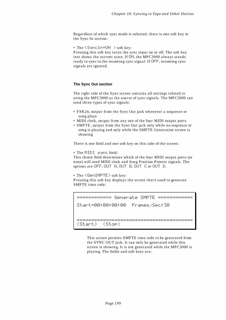
Page 199
Chapter 10: Syncing to Tape and Other Devices
Regardless of which sync mode is selected, there is one soft key inthe Sync In section:
• The <SyncIn=ON > soft key:Pressing this soft key turns the sync input on or off. The soft keytext shows the current state. If ON, the MPC3000 always standsready to sync to the incoming sync signal. If OFF, incoming syncsignals are ignored.
The Sync Out section
The right side of the Sync screen contains all settings related tousing the MPC3000 as the source of sync signals. The MPC3000 cansend three types of sync signals:
• FSK24, output from the Sync Out jack whenever a sequence orsong plays
• MIDI clock, output from any one of the four MIDI output ports• SMPTE, output from the Sync Out jack only while no sequence or
song is playing and only while the SMPTE Generation screen isshowing
There is one field and one soft key on this side of the screen:
• The MIDI sync field:This choice field determines which of the four MIDI output ports (ornone) will send MIDI clock and Song Position Pointer signals. Theoptions are OFF, OUT A, OUT B, OUT C or OUT D.
• The <GenSMPTE> soft key:Pressing this soft key displays the screen that’s used to generateSMPTE time code:
============ Generate SMPTE ============
Start=00:00:00:00 Frames/Sec:30
========================================<Start> <Stop>
This screen permits SMPTE time code to be generated fromthe SYNC OUT jack. It can only be generated while thisscreen is showing. It is not generated while the MPC3000 isplaying. The fields and soft keys are:
Page 200
Chapter 10: Syncing to Tape and Other Devices
• The Start= field:This is the SMPTE timecode number at which the generatedtime code will start. The four parts of the field are hours,minutes, seconds and frames. Normally, this should be set to00:00:00:00. While the SMPTE code is being generated(when <Start> is pressed), this field will continuouslyupdate to show the current timecode number being output.When <Stop> is pressed, the starting value will beredisplayed.
• The Frames/sec field:This field has the same function as the similarly-labeledfields in the Tempo screen and the Sync Input section of theSync screen. Use it to select which of the four SMPTE modes(30, 29.97 drop, 24 or 25) you wish to generate. Be sure toset the proper SMPTE mode in this field before recordingthe SMPTE signal to tape.
• The <Start> soft key:Pressing this soft key starts SMPTE generation.
• The <Stop> soft key:Pressing this soft key stops SMPTE generation.
Page 201
Chapter 10: Syncing to Tape and Other Devices
Syncing to Tape and Other Devices: Examples
This section provides step-by-step examples of how to sync to each ofthe five sync signals.
Syncing to MIDI Clock
To generate MIDI clock with Song Position Pointer:
1. In the Sync screen, set the MIDI sync field (in the Sync Outsection) to the MIDI port that you want the sync signal to be sentfrom (OUT A, OUT B, OUT C or OUT D.)
2. Play a sequence (or, if in Song mode, play a song). While playing,the MIDI clock signal will be sent out over MIDI at the currenttempo.
To slave the MPC3000 to MIDI clock signal received from anexternal device:
1. Connect a MIDI cable from the MIDI output of the device sendingMIDI clock to one of the MPC3000’s MIDI inputs.
2. In the Sync screen, set the Mode field (in the Sync In section) toMIDI CLOCK and set the MIDI input field to the number ofthe MIDI input to which you have connected the cable.
3. In the Sync screen, SOFT KEY 1 should show the text<SyncIn=ON>. If it shows <SyncIn=OFF>, press it once.
4. Set up your MPC3000 sequence or song to play as normal.5. Start the external device sending MIDI clock. The MPC3000 will
automatically play in sync.
Syncing to SMPTE
To record a SMPTE track:
SMPTE timecode can only be generated by the MPC3000 when it isnot playing. Before recording any music to tape, record (“stripe”)SMPTE timecode onto one track of your multitrack tape.
Page 202
Chapter 10: Syncing to Tape and Other Devices
1. Connect the SYNC OUT jack of the MPC3000 to the input of onetrack of your multitrack tape recorder.
2. Access the Generate SMPTE screen by pressing TEMPO/SYNC,then the <SyncScreen> soft key, followed by the<GenSMPTE> soft key.
3. Set the Start field to 00:00:00:00 or the desired start time.4. Set the Frames/sec field to the desired SMPTE mode. In the
U.S., the standard for music production using SMPTE is 30.5. To set the proper recording level, press <Start>; this will start
the SMPTE generation. Then set the recording level of the taperecorder to about -3dB. Press <Stop> to stop generating.
6. Start the tape recorder recording.7. Press <Start> to start generating SMPTE time code.8. Wait until enough time has passed to allow for the total duration
of your song (plus a litte extra time to allow for changes in thearrangement). Press <Stop> to stop SMPTE generation, andthen stop the tape recorder. Your tape now contains the SMPTEcode.
To play back a sequence in sync to SMPTE:
COMMENT: The I-0055 SMPTE option is required; see theAppendix for more information
1. Connect the output of the tape track that contains the SMPTEsignal to the SYNC IN jack of the MPC3000. Set the SYNC INLEVEL knob to about 1/2.
2. From the Play/Record screen, select the sequence that you intendto record to tape.
3. Press the TEMPO/SYNC key and set the Tempo Source fieldto SEQUENCE. This causes the MPC3000 to use the temposetting that’s stored within the sequence, so that it will always beremembered. (This is true even when the sequence is saved todisk and later recalled, as master tempo settings are only savedin PAR files, not in ALL files.) It is important for the MPC3000 toremember the tempo setting because SMPTE time code does notprovide any tempo information.
4. Set the Frames field to the SMPTE frame rate that matches theSMPTE timecode that will be received. If this field is set to adifferent frame rate than that of the incoming timecode, theplayback tempo will be inaccurate.
5. Set the Mode field in the Sync screen to SMPTE and press SOFTKEY 1 until it shows <SyncIn=ON>.
6. While in the Sync screen, set the Start field to the SMPTElocation you want your sequence to start at. If you don’t know,use 00:00:10:00.00. This will cause your sequence to start at alocation 10 seconds after the start of the SMPTE code you re-corded in this example. This will allow you to add some new partsin that first 10 seconds if you should later decide to do so. Thissetting only applies to the active sequence, so be sure that the
Page 203
Chapter 10: Syncing to Tape and Other Devices
sequence you intend to use is selected before setting this param-eter.
7. Press the MAIN SCREEN key to return to the Play/Recordscreen.
8. Play the tape from a point just before the beginning of theSMPTE timecode. Once the code reaches the start time you haveentered into the Start field, the MPC3000 will automaticallystart playing from the beginning of the sequence, and will notstop until the sequence comes to its end (or the tape recorder isstopped). To stop playback early, press the STOP key on theMPC3000 or stop the tape recorder. To play in sync from alocation in the middle of your sequence, fast-forward the taperecorder to any point within the duration of the sequence andstart playback of the tape. The MPC3000 will start playing fromthe correct location within the sequence.
COMMENT: If the MPC3000 doesn’t respond properly to thesync signal, try adjusting the SYNC IN LEVEL control onthe rear panel. Find the lowest setting to which the MPC3000responds, then increase the level by about 1/4 turn.
COMMENT: When playing a sequence from bar 1 in responseto incoming SMPTE, the timing of the first note in bar 1 willbe slightly late. To get around this problem, insert a blankbar at the start of the sequence (or song). This will cause thelate timing to occur within the initial blank bar, so that thetiming is stable well before the notes (starting in the secondbar) start playing.
To play back a song (in Song mode) in sync to the SMPTE timecode on tape:
1. Connect the output of the tape track that contains the SMPTEsignal to the SYNC INPUT of the MPC3000. Set the SYNC INLEVEL knob to about 1/2.
2. In the Tempo/Sync screen, set the Tempo source field toSEQUENCE. This causes the MPC3000 to use the tempo settingthat’s stored within the sequence, so that it will always beremembered. (This is true even when the sequence is saved todisk and later recalled, as master tempo settings are only savedin PAR files, not in ALL files.) Then, set each sequence in yoursong to the desired tempo setting. It is important for theMPC3000 to remember the tempo setting because SMPTEtimecode does not provide any tempo information.
3. In the Sync screen, set the Mode field to SMPTE. Press SOFTKEY 1 until it shows <SyncIn=ON>, and set the Frames fieldto the same SMPTE frame rate as that of the incoming SMPTEsignal. Ignore the Start field because this start time appliesonly to active sequences, not to songs.
4. Press the SONG key and set up your song to play as you want itto. In the Song screen, set the SMPTE Start field to the
Page 204
Chapter 10: Syncing to Tape and Other Devices
SMPTE location where you want your song to start. If you don’tknow, use 00:00:10:00.00. This will cause your song to start at alocation 10 seconds after the start of the SMPTE code you re-corded in the example above. This will allow you to add some newparts in those first 10 seconds if you should later decide to do so.This setting only applies to the active song, so be sure that thesong you intend to use is selected before setting this parameter.
5. Play the tape from a point just before the beginning of theSMPTE timecode. Once the code reaches the start time you haveentered in the SMPTE Start field, the MPC3000 will automati-cally start playing from the beginning of the song and will notstop until the song has completed (or the tape recorder isstopped). To stop playback early, press the STOP key on theMPC3000 or stop the tape recorder. To play in sync from alocation in the middle of your song, fast-forward the tape re-corder to any point within the duration of the song and startplayback of the tape. The MPC3000 will start playing from thecorrect location within the song.
Syncing to MIDI Time Code
MIDI Time Code is SMPTE timecode encoded over MIDI. Since it isa MIDI signal, it cannot be recorded on tape. Rather, it is used tosync to devices such as drum machines and sequencers. TheMPC3000 does not generate MIDI Time Code, but does sync to itwhen received from an external source.
To play back a sequence or song in sync to MIDI Time Code:
Use the same instructions as if playing a sequence or a song in syncto SMPTE (earlier in this chapter), except that in the Sync screenselect MIDI TIME CODE in the Mode field and set the MIDI infield to the number of the MIDI input where the MIDI time codesignal is connected.
Syncing to FSK24
Of the five possible sync modes in the MPC3000, only three can beused to sync to tape: FSK24, 1/4 NOTE CLICKS, and SMPTE (anoption on the MPC3000). SMPTE is preferable for many reasons,and is the standard for professional use. 1/4 NOTE CLICKS can beused with tape, but since it provides low timing resolution it is not agood first choice for syncing to tape. FSK24 was the tape syncmethod in general use for musical applications prior to the
Page 205
Chapter 10: Syncing to Tape and Other Devices
acceptance of SMPTE, and is still used by many drum machines andsequencers. If you don’t have the SMPTE option, FSK24 provides avery good alternative.
FSK24 sync code is generated in real time as the MPC3000 plays.Remember that FSK24 sync code contains tempo information, so itis important that the tempo is properly set before the FSK sync toneis recorded to tape.
To record the sync tone to tape:
1. Connect the SYNC OUT jack of the MPC3000 to the input of atrack on your multitrack tape recorder.
2. Set the recording level of the sync tone’s track to -3 dB. (TheFSK24 sync tone is always emitted from the SYNC OUT jack,even when the MPC3000 is stopped.)
3. Create your sequence or song on the MPC3000, making sure thatall tempo settings and tempo changes have been finalized. It isimportant that the tempo be exactly as you want it throughoutthe sequence or song because the FSK24 sync tone contains alltempo information and cannot be changed after recording.
4. Put the tape recorder into record mode and start recording.5. Play the sequence or song on the MPC3000. Let it play until the
its end, then stop both the MPC3000 and the tape recorder.
To play back the MPC3000 in sync to the tape:
1. Connect the output of the tape track that contains the FSK24signal to the SYNC IN jack of the MPC3000.
2. Set the SYNC IN LEVEL control on the rear panel to about 1/2.3. In the Sync screen, set the Mode field (Sync Input section) toFSK24 and press SOFT KEY 1 until it reads <SyncIn=ON>.
4. Set up the MPC3000 to play your sequence or song.5. Rewind the tape to just before the point at which you started
recording the sync tone.6. Play the tape. Once the tape reaches the point where the sync
tone starts, the MPC3000 will begin playing its parts in perfectsync. Note that the current tempo setting is not used; tempo isprovided from the sync tone on tape. To use FSK24, you mustalways start the tape from the beginning of the recording, as inthis example.
COMMENT: If the MPC3000 doesn’t respond to the syncsignal, try adjusting the SYNC IN LEVEL control on therear panel. Find the lowest setting at which the MPC3000responds, then increase the level by about 1/4 turn.
Page 206
Chapter 10: Syncing to Tape and Other Devices
Syncing to 1/4-note Clicks
This method of syncing uses any cleanly recorded, percussive soundplaying on 1/4-notes as a sync source. This allows you to addsequenced parts to a recording that contains no sync track. Forexample, the sync track could consist of a drummer recording atrack of 1/4-note drumstick clicks throughout the song. Using thismethod of sync, the playback tempo is derived from the external1/4-note clicks.
To play the MPC3000 in sync to 1/4-note clicks:
1. Connect the output of the tape track that contains the 1/4-noteclick signal (or other percussive audio source) into the MPC3000’sSYNC IN jack, and set the SYNC IN LEVEL to about 1/2.
3. In the Sync screen, set the Mode field (Sync input section) to 1/4NOTE CLICKS.
4. Set up the MPC3000 to play your sequence or song. Set theplayback tempo as close as possible to the intended tempo. Theinternal tempo will be used for the time between the first andsecond clicks received.
5. Rewind the tape to just before the point at which the 1/4-noteclicks begin.
6. Play the tape. Once the tape reaches the first click, the MPC3000will begin playing. It will start at the current internal tempo,then it will gradually use the timing of the clicks for its tempo. Touse 1/4 NOTE CLICK sync, you must always start the tape fromthe beginning of the clicks, as in this example.
COMMENT: To smooth out any variations in tempo, theplayback tempo is averaged over time. It is possible for theMPC3000 to follow slight tempo changes, but larger changeswill cause it to temporarily lag behind or lead. It is possibleto use almost any clean signal rather than metronome clicks,but the signal used must be very distinct and short, such as acowbell or closed hi-hat, and there must be a minimum ofbackground noise. Adjusting the sync input level control willhelp to minimize triggering from background noise.
Page 207
Chapter 11: MIDI Function
Chapter 11:MIDI Functions
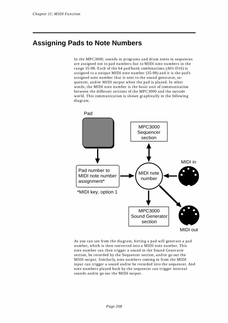
Page 208
Chapter 11: MIDI Function
Assigning Pads to Note Numbers
In the MPC3000, sounds in programs and drum notes in sequencesare assigned not to pad numbers but to MIDI note numbers in therange 35-98. Each of the 64 pad/bank combinations (A01-D16) isassigned to a unique MIDI note number (35-98) and it is the pad’sassigned note number that is sent to the sound generator, se-quencer, and/or MIDI output when the pad is played. In otherwords, the MIDI note number is the basic unit of communicationbetween the different sections of the MPC3000 and the outsideworld. This communication is shown graphically in the followingdiagram.
MPC3000 Sequencer
section
MPC3000 Sound Generator
section
MIDI note number
MIDI in
MIDI out
Pad
Pad number to MIDI note number assignment*
*MIDI key, option 1
As you can see from the diagram, hitting a pad will generate a padnumber, which is then converted into a MIDI note number. Thisnote number can then trigger a sound in the Sound Generatorsection, be recorded by the Sequencer section, and/or go out theMIDI output. Similarly, note numbers coming in from the MIDIinput can trigger a sound and/or be recorded into the sequencer. Andnote numbers played back by the sequencer can trigger internalsounds and/or go out the MIDI output.
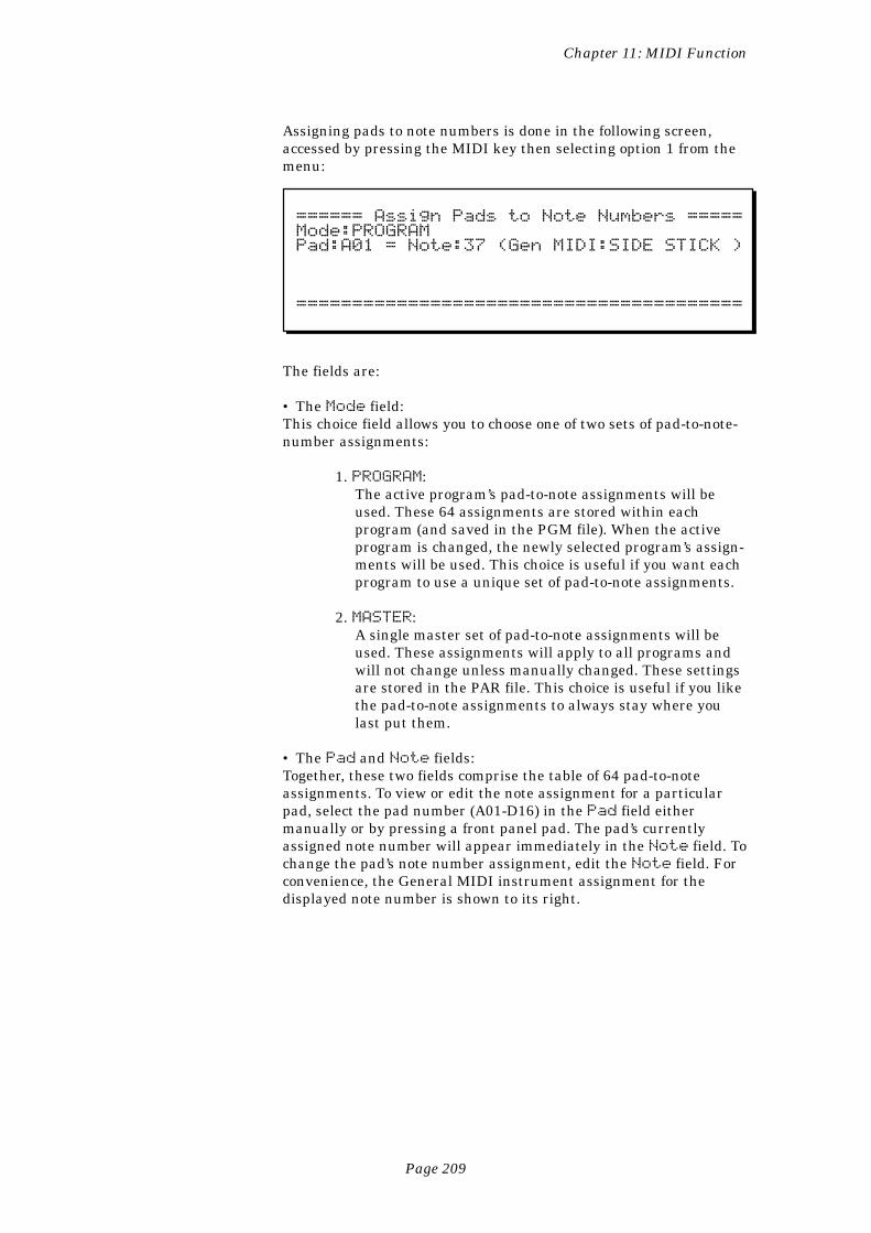
Page 209
Chapter 11: MIDI Function
Assigning pads to note numbers is done in the following screen,accessed by pressing the MIDI key then selecting option 1 from themenu:
====== Assign Pads to Note Numbers =====Mode:PROGRAMPad:A01 = Note:37 (Gen MIDI:SIDE STICK )
========================================
The fields are:
• The Mode field:This choice field allows you to choose one of two sets of pad-to-note-number assignments:
1. PROGRAM:The active program’s pad-to-note assignments will beused. These 64 assignments are stored within eachprogram (and saved in the PGM file). When the activeprogram is changed, the newly selected program’s assign-ments will be used. This choice is useful if you want eachprogram to use a unique set of pad-to-note assignments.
2. MASTER:A single master set of pad-to-note assignments will beused. These assignments will apply to all programs andwill not change unless manually changed. These settingsare stored in the PAR file. This choice is useful if you likethe pad-to-note assignments to always stay where youlast put them.
• The Pad and Note fields:Together, these two fields comprise the table of 64 pad-to-noteassignments. To view or edit the note assignment for a particularpad, select the pad number (A01-D16) in the Pad field eithermanually or by pressing a front panel pad. The pad’s currentlyassigned note number will appear immediately in the Note field. Tochange the pad’s note number assignment, edit the Note field. Forconvenience, the General MIDI instrument assignment for thedisplayed note number is shown to its right.
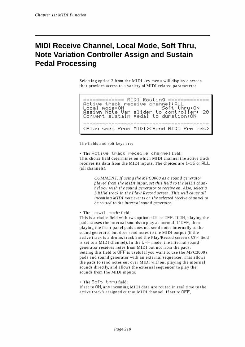
Page 210
Chapter 11: MIDI Function
MIDI Receive Channel, Local Mode, Soft Thru,Note Variation Controller Assign and SustainPedal Processing
Selecting option 2 from the MIDI key menu will display a screenthat provides access to a variety of MIDI-related parameters:
============= MIDI Routing =============Active track receive channel:ALLLocal mode:ON Soft thru:ONAssign Note Var slider to controller: 20Convert sustain pedal to duration:ON
========================================<Play snds from MIDI><Send MIDI frm pds>
The fields and soft keys are:
• The Active track receive channel field:This choice field determines on which MIDI channel the active trackreceives its data from the MIDI inputs. The choices are 1-16 or ALL(all channels).
COMMENT: If using the MPC3000 as a sound generatorplayed from the MIDI input, set this field to the MIDI chan-nel you wish the sound generator to receive on. Also, select aDRUM track in the Play/Record screen. This will cause allincoming MIDI note events on the selected receive channel tobe routed to the internal sound generator.
• The Local mode field:This is a choice field with two options: ON or OFF. If ON, playing thepads causes the internal sounds to play as normal. If OFF, thenplaying the front panel pads does not send notes internally to thesound generator but does send notes to the MIDI output (if theactive track is a drums track and the Play/Record screen’s Chn fieldis set to a MIDI channel). In the OFF mode, the internal soundgenerator receives notes from MIDI but not from the pads.Setting this field to OFF is useful if you want to use the MPC3000’spads and sound generator with an external sequencer. This allowsthe pads to send notes out over MIDI without playing the internalsounds directly, and allows the external sequencer to play thesounds from the MIDI inputs.
• The Soft thru field:If set to ON, any incoming MIDI data are routed in real time to theactive track’s assigned output MIDI channel. If set to OFF,
Page 211
Chapter 11: MIDI Function
they aren’t. If you are using a single keyboard synthesizer (thekeyboard and sound generator are together in one unit), this fieldshould be set to OFF (or set the keyboard’s Local Control to OFF). Inthis case, there is no need for incoming MIDI notes to be immedi-ately sent out to the synthesizer’s sound generator because it isalready receiving notes directly from its keyboard. If you are using aMIDI master keyboard and separate synthesizer modules, set thisfield to ON. This way, the notes played on the keyboard will play thesynthesizer modules in real time.
COMMENT: When the MIDI thru field is set to ON, becareful to avoid a MIDI feedback loop in your external MIDIcables and devices. A MIDI feedback loop occurs when anoutput MIDI message, because of some incorrect externalMIDI connection, is immediately sent back to the input, thenit is immediately sent back out (because the MIDI thrufield is ON), then back in, then back out, etc. If this occurs,the MPC3000 could stop operating until one of the MIDIcables is disconnected. To avoid this, be very careful inconnecting your external MIDI cables and devices to preventa direct signal path from the MPC3000’s MIDI output to itsMIDI input.
• The Assign Note Var slider to controller field:The function of the Note Variation Slider can be remotely duplicatedby any external MIDI device sending MIDI control change mes-sages. Set this field to the number (0-127) of the incoming controllerthat you want to affect the current slider value. For example, to usea MIDI keyboard’s modulation wheel to duplicate the function of theNote Variation Slider, connect the keyboard’s MIDI output to theMPC3000’s MIDI input and set this field to 1, which is the MIDIcontroller number for the keyboard’s modulation wheel.
• The Convert sustain pedal to duration field:In all other sequencers, sustain pedal messages (MIDI controller 64)are recorded as received into the sequence along with the notes.This presents the following problems:
1. If you delete or erase a section of the sequence thatcontained a Sustain Off message, all notes after thatlocation will be sustained until the next Sustain Onmessage.
2. If you play two or more tracks into the same MIDI outputchannel and only one track has sustain pedal informa-tion, the notes on the other tracks will also be sustained.
3. If you merge a track with sustain pedal information into atrack without sustain pedal information, notes on theresultant track will be sustained.
4. If you overdub notes into a track containing sustain pedalinformation, the new notes will be sustained.
Page 212
Chapter 11: MIDI Function
The MPC3000 eliminates these problems by specially processingsustain pedal messages. If the Convert sustain pedal toduration field is set to ON, when the MPC3000 receives a SustainOn message during record, it will NOT record it. Instead, any notesthat are currently pressed will be internally held on, even after theyare released, until a Sustain Off message is received. The result isthat the individual durations of notes are lengthened, so unwantedtransfer of sustain information to other notes on the same MIDIchannel is impossible. This has the added advantage of allowing youto adjust durations of sustained notes individually in Step Editmode.
There are some situations in which converting sustain pedal toduration is undesirable:
1. On some synthesizers, this special sustain method willcause the synthesizer to ignore any new notes playedafter all available voices are used, because the synthe-sizer thinks the keys are still held.
2. Some synthesizers have the ability to use MIDI controller64 for other purposes than sustain, so it is desirable torecord it into the sequence.
For these reasons, the MPC3000’s special sustain processing can bedefeated. To defeat this special feature and record MIDI sustainmessages (controller 64) into sequences, set this field to OFF.
• SOFT KEYS 1 and 2—<Play snds from MIDI>:Pressing either of these soft keys presents a screen that explainshow to play the MPC3000’s internal sounds from its MIDI input.These soft keys are only used to display information—they don’taffect any data in the MPC3000.
• SOFT KEYS 3 and 4 —<Send MIDI frm pds>:Pressing either of these soft keys presents a screen that explainshow to send note events out over MIDI when the MPC3000’s padsare played. These soft keys are only used to display information—they don’t affect any data in the MPC3000.
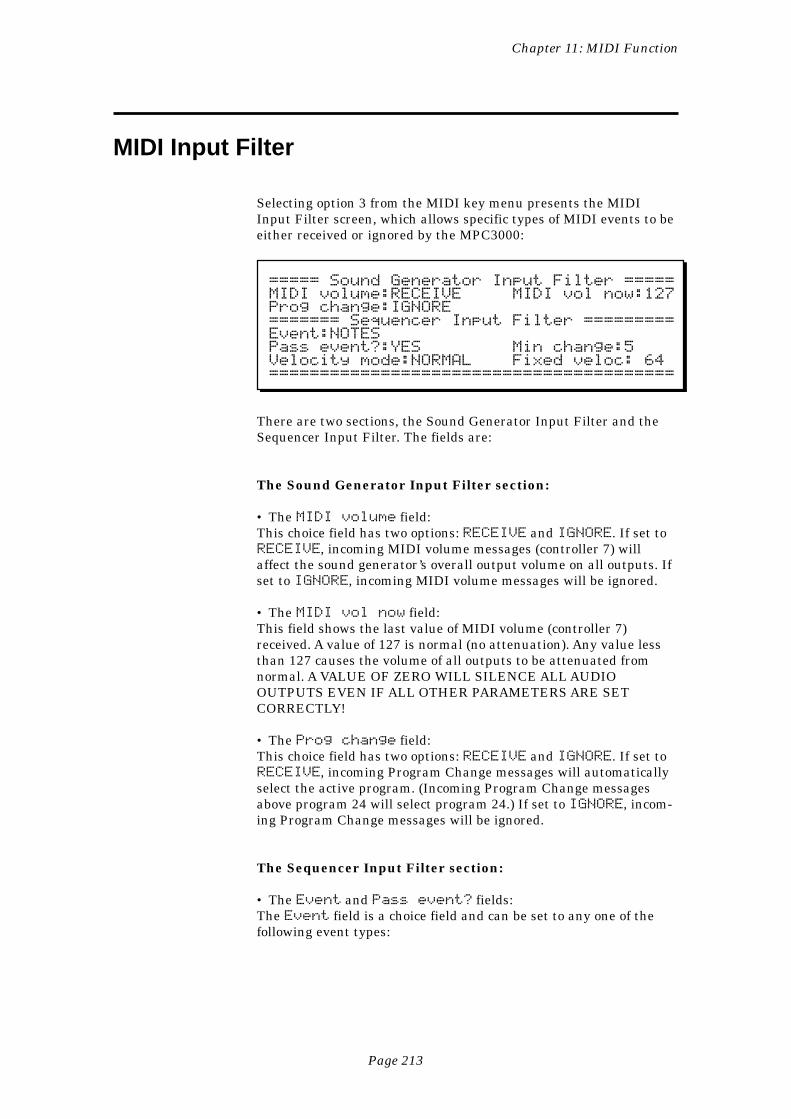
Page 213
Chapter 11: MIDI Function
MIDI Input Filter
Selecting option 3 from the MIDI key menu presents the MIDIInput Filter screen, which allows specific types of MIDI events to beeither received or ignored by the MPC3000:
===== Sound Generator Input Filter =====MIDI volume:RECEIVE MIDI vol now:127Prog change:IGNORE======= Sequencer Input Filter =========Event:NOTESPass event?:YES Min change:5Velocity mode:NORMAL Fixed veloc: 64========================================
There are two sections, the Sound Generator Input Filter and theSequencer Input Filter. The fields are:
The Sound Generator Input Filter section:
• The MIDI volume field:This choice field has two options: RECEIVE and IGNORE. If set toRECEIVE, incoming MIDI volume messages (controller 7) willaffect the sound generator’s overall output volume on all outputs. Ifset to IGNORE, incoming MIDI volume messages will be ignored.
• The MIDI vol now field:This field shows the last value of MIDI volume (controller 7)received. A value of 127 is normal (no attenuation). Any value lessthan 127 causes the volume of all outputs to be attenuated fromnormal. A VALUE OF ZERO WILL SILENCE ALL AUDIOOUTPUTS EVEN IF ALL OTHER PARAMETERS ARE SETCORRECTLY!
• The Prog change field:This choice field has two options: RECEIVE and IGNORE. If set toRECEIVE, incoming Program Change messages will automaticallyselect the active program. (Incoming Program Change messagesabove program 24 will select program 24.) If set to IGNORE, incom-ing Program Change messages will be ignored.
The Sequencer Input Filter section:
• The Event and Pass event? fields:The Event field is a choice field and can be set to any one of thefollowing event types:

Page 214
Chapter 11: MIDI Function
NOTES
PROGRAM CHANGE
PITCH BEND
CHANNEL PRESSURE
POLY PRESSURE
SYSTEM EXCLUSIVE
MIXER VOLUME
MIXER PAN
OUTPUT/EFFECT LEVEL
C0-BANK SELECT MSB
C1-MODULATION WHEEL
C2-BREATH CONT
.
.
.
C127-POLY MODE ON
TUNE REQUEST
While one of these event types is selected, the Pass event? fielddisplays either YES, indicating that the event will be recorded intosequences, or NO, indicating that the event type will be removedfrom the MIDI input data stream when encountered. To change thestatus of a particular event, first select the event in the Eventfield, then set the Pass event? field to the desired status—YES
or NO.
COMMENT: An example of a good use of this function is toprevent channel pressure data from being recorded into yourtracks. If you are using a keyboard that produces channelpressure messages, all of these continuous messages willnormally be recorded into the track, whether your synthesizeruses them or not. This will cause a lot of extra sequencememory to be used and will cause the sequencer to workmuch harder to play all of these messages, possibly causingnote delays. To avoid this, turn off the recording of continu-ous controller messages unless your synthesizer is usingthem. To do this, select CHANNEL PRESSURE in theEvent field, then select NO in the Pass event? field.
• The Min change field:This field only appears if the Event field is set to PITCH,CHANNEL PRESSURE, MIXER VOLUME, MIXER PAN,OUTPUT/EFFECT LEVEL, or controllers 0 through 31. These areall continuous controller event types, meaning that large numbers ofthese individual events are used to simulate a gradual change in thespecified parameter. For example, when you move a pitch bendwheel on a keyboard, a large number of pitch bend events areoutput from the keyboard, and all of them are recorded into theactive track. The problem with recording all of these events is thatthey use a large amount of memory and they cause the internalcomputer to work very hard, causing possible timing delays if largeamounts of these events exist in a sequence. In many cases,however, many more of these events are output from the keyboardthan are necessary to produce the desired effect.
Page 215
Chapter 11: MIDI Function
The Min change field is used to thin out the event data for theabove specified event types, thereby reducing the total number ofevents that will be recorded into tracks. It works by only recordingevents that have changed more than a specified amount since thelast received event of the same type. This amount is set in the Minchange field. As with the Pass event? field, the Min changefield shows the value associated with the event type shown in theEvent field. For example, to thin out incoming channel pressureevents:
1. Set the Event field to CHANNEL PRESSURE.2. Set the Pass event? field to YES.3. Set the Min change field to 5.
This means that an incoming channel pressure message will berecorded only if its value has changed by more than 5 incrementsfrom the last value received. The range of this field is 0-127, with127 being the full range of the controller. (Pitch bend is an excep-tion—even though the pitch bend messages actually have a range of± 8191, 0-127 represents the full range here. For example, to specifythat only a change of 10% or more in the total range of the bendwheel may be recorded, enter a 12 here, because 12 is approximately10% of 127, which here represents the full range of the bend wheel.)If the Min change value is set too high, a stepping effect will beheard as the continuous controller is moved. Try to pick a value thatis low enough so that the stepping is not noticeable.
• The Velocity mode and Fixed veloc fields:Incoming MIDI note events are normally recorded into the sequencewith their velocity values intact, permitting the recording of dynam-ics. These two fields permit the incoming velocity data to be ignored,if desired, and a fixed value substituted for each incoming note. TheVelocity mode field has two options: NORMAL and FIXED. Ifset to FIXED, all incoming velocity values are replaced by the valuespecified in the Fixed veloc field (1-127).
Page 216
Chapter 11: MIDI Function
Turning All Notes Off
Occasionally, a note from an externally-connected synthesizer maystick on. This may be due to sending the synthesizer too much data,or switching an external MIDI switching box at the wrong time, ormany other reasons. Regardless of the reason, to turn all notes offon all MIDI channels and ports, press the MIDI key and selectoption 4, All notes off. The MPC3000 will send MIDI NoteOff messages for every note (0-127) on every channel.
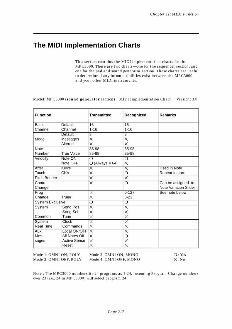
Page 217
Chapter 11: MIDI Function
The MIDI Implementation Charts
This section contains the MIDI implementation charts for theMPC3000. There are two charts—one for the sequencer section, andone for the pad and sound generator section. These charts are usefulto determine if any incompatibilities exist between the MPC3000and your other MIDI instruments.
Model: MPC3000 (sound generator section) MIDI Implementation Chart Version: 3.0
Function Transmitted Recognized Remarks
Basic Default 16 16Channel Channel 1-16 1-16
Default 3 3Mode Messages
Altered
Note 35-98 35-98Number True Voice 35-98 35-98Velocity Note ON
Note OFF (Always = 64)
After Key’s Used in NoteTouch Ch’s Repeat featurePitch Bender
Control Can be assigned toChange Note Variation SliderProg 0-127 See note belowChange True# 0-23System Exclusive
System :Song Pos :Song Sel
Common :Tune
System :Clock Real Time :Commands
Aux :Local ON/OFF Mes- :All Notes Off sages :Active Sense
:Reset
Mode 1: OMNI ON, POLY Mode 2: OMNI ON, MONO : YesMode 3: OMNI OFF, POLY Mode 4: OMNI OFF, MONO : No
Note : The MPC3000 numbers its 24 programs as 1-24. Incoming Program Change numbersover 23 (i.e., 24 in MPC3000) will select program 24.
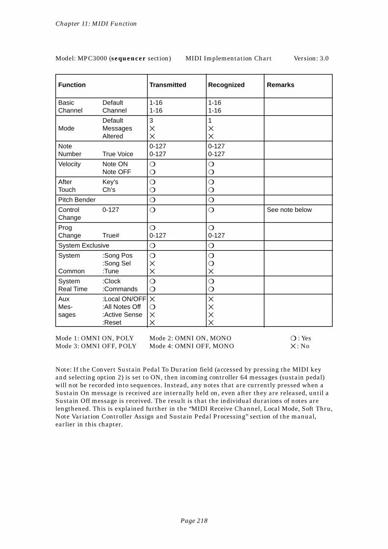
Page 218
Chapter 11: MIDI Function
Model: MPC3000 (sequencer section) MIDI Implementation Chart Version: 3.0
Function Transmitted Recognized Remarks
Basic Default 1-16 1-16Channel Channel 1-16 1-16
Default 3 1Mode Messages
Altered
Note 0-127 0-127Number True Voice 0-127 0-127
Velocity Note ON Note OFF
After Key’s Touch Ch’s
Pitch Bender
Control 0-127 See note belowChange
Prog Change True# 0-127 0-127
System Exclusive
System :Song Pos :Song Sel
Common :Tune
System :Clock Real Time :Commands
Aux :Local ON/OFF Mes- :All Notes Off sages :Active Sense
:Reset
Mode 1: OMNI ON, POLY Mode 2: OMNI ON, MONO : YesMode 3: OMNI OFF, POLY Mode 4: OMNI OFF, MONO : No
Note: If the Convert Sustain Pedal To Duration field (accessed by pressing the MIDI keyand selecting option 2) is set to ON, then incoming controller 64 messages (sustain pedal)will not be recorded into sequences. Instead, any notes that are currently pressed when aSustain On message is received are internally held on, even after they are released, until aSustain Off message is received. The result is that the individual durations of notes arelengthened. This is explained further in the “MIDI Receive Channel, Local Mode, Soft Thru,Note Variation Controller Assign and Sustain Pedal Processing” section of the manual,earlier in this chapter.

Page 219
Appendix
Appendix
Page 220
Appendix
Technical Specifications
General
• Display: 320 character (240 x 64 dot graphic) LCD• Disk drive: 3.5 inch HD (1.44MB formatted)• CPU: V53 @ 16MHz• Dimensions: 440(W) x 121(H) x 405(D) mm• Weight: 9 kg• Power requirements: 120 VAC 60Hz 40W
220-240 VAC 50Hz
Sound Generator
• Sampling rate: 44.1kHz (frequency response: 20Hz-20kHz)• Sampling capacity: 2MB standard (21.9 seconds mono or 10.9
seconds stereo), expandable to 16MB (188.3 seconds mono or 94.1seconds stereo).
• Data format: 16-bit linear• Dynamic filtering: 12 dB/Octave dynamic resonant lowpass filter
per voice• Maximum sounds in memory: 128• Number of sound programs: 24• Sound assignments per program: 64• Simultaneous voices: 32
Sequencer
• Maximum notes: 75,000• Resolution: 96 parts per 1/4-note (ppq)• Sequences: 99• Tracks per sequence: 99• MIDI output channels: 64 (16 channels x 4 output ports)• Song mode: 20 songs, 250 steps per song• Drum pads: 16 (velocity and pressure sensitive)• Drum pad banks: 4• Sync modes: MIDI Time Code, MIDI clock, FSK 24, 1/4-note clicks
and SMPTE (optional). SMPTE frame rates supported are 24, 25,29.97 drop and 30.
Rear Panel Inputs/Outputs
• Record input sensitivity (both L and R): (HI gain) -58dBm, 45kΩ;(MID gain) -38dBm, 45kΩ; (LO gain) -18dBm, 45kΩ
• Digital sampling input: S/PDIF• Stereo output level: 6dBm, 600Ω
Page 221
Appendix
• Level of 8 individual outputs: 6dBm, 600Ω• Sync/Trigger input level: 0.5V p-p level (with input control at
maximum)• Sync output level: 2.5V p-p, impedance 600Ω• MIDI inputs: 2 (mergeable)• MIDI outputs: 4 (independent)• SCSI port: 1 (Apple 25-pin D-type SCSI connector)• Headphone output: 1• Foot Switch inputs: 2 (independently assignable)
Page 222
Appendix
Answers to Frequent Questions
If you discover a problem in your MPC3000, we would appreciate itif you would please read the relevant section of the manual to makesure you correctly understand the operation before you before callyour Akai representative. Here are some answers to commonlyasked questions and problems:
When I play a particular sequence or song, the timing is irregular.What’s wrong?
If you notice a timing irregularity in song mode at the point oftransition from one sequence into another, the problem may becaused by assignments of the Program field (in the Play/Recordscreen) for the new playing sequence. When a new sequence isencountered in a song, any program assignments for the tracks inthe newly selected sequence are sent out at the moment that thesequence starts to play. This can present a problem because mostsynthesizers require time to change programs, which can cause anynotes existing at the start of the new sequence to be delayed. Thisdelay is brief in most synthesizers, but is usually enough to cause atiming irregularity at the start of the sequence. To avoid this prob-lem, remove any assignments of the Program field for all sequencesexcept the first sequence in the song. If you are encountering thesame problem when changing sequences while playing (in whichcase the new sequence begins immediately following the currentrepetition of the current sequence), then use the same solution:remove all program assignments for the newly selected sequence.
If the timing irregularity does not exist at the beginning of a se-quence, it may be due to the sequence containing a large systemexclusive message at that location, in which case the MPC3000must finish processing the system exclusive message before playingany other notes at that location. If this is the case, erase or move thesystem exclusive event that is causing the problem.
If the timing irregularity does not exist at the beginning of a se-quence and is not due to a system exclusive event, it may be due tohaving too many notes (more than approximately 10 or 12) at onetick in the sequence. If so, this could cause the last notes occurringat this location to be delayed. This problem is aggravated at fastertempos. This problem exists to some degree in all sequencers, and isdue to the fact that there is a finite number of notes that the inter-nal computer can process at one time. However, this will NOT causethe sequence to slip out of sync when syncing to an external syncsource. To reduce the processing requirement in your sequence, trythe following:
Page 223
Appendix
1. Erase any unnecessary events from the sequence. For example,erase any channel pressure, poly pressure and system exclusiveevents if you are not using them. Many keyboards send out largeamounts of channel pressure messages while playing, which arerecorded into your tracks. If you are not using these messages,removing them from the tracks will improve the playback timing.To block these messages from being recorded into new sequences,use the MIDI Input Filter.
2. Erase any tracks that are turned off but still exist in the se-quence. Turning a track off (the On field in the Play/Recordscreen) eases the processing requirement for playing the track,but doesn’t eliminate it.
3. If you only need to improve the timing while recording yoursequence to tape and are using a sync tone, then record thesequence to tape a few tracks at a time, and turn off or erase thetracks you are not using on each pass. By eliminating the needfor the MPC3000 to process the tracks that aren’t being heard,the timing of the remaining tracks will be improved.
4. In the Play/Record screen, disable Record Ready by selecting adifferent sequence, then the original one. This slightly lessensthe processing requirement.
5. If the delay is due to many notes existing at one tick, then eitherdelete some of the notes or spread them around to neighboringticks.
How can I reduce the time required for the “Analyzing sequence.Please wait...” message?
This message is most noticeable during song mode. It appears onceafter the song is edited and when the song screen is entered while along song is selected. The reason for this delay is that the MPC3000must scan through the entire song to learn where the start of eachbar is. Once this is done, any rewind, fast forward or locate opera-tion will be very fast. Also, response to incoming SMPTE will benearly immediate. Unfortunately, there is no way to reduce the timerequired for this message other than reducing the complexity of thesong.
I want to use the MPC3000 only as a sound generator receivingnotes from another sequencer. How can I get it to play from onlyone MIDI channel?
1. Press the MIDI key and select option 2. In the screen that ap-pears, set the Active track receive channel field tothe channel you want the MPC3000 to receive on.
2. In the Play/Record screen, set the Type field to DRUM or select atrack that has a Type of DRUM.
3. Load in the desired program.
Page 224
Appendix
If you ever forget these instructions, just press the <Play sndsfrom MIDI> soft key. It’s in the screen accessed by pressing theMIDI key and selecting option 2.
I want to use the MPC3000’s pads to program drum parts on anexternal sequencer, but I can’t get any of the MIDI outputs to sendnote-on messages when I play the pads. How do I do it?
1. In the Play/Record screen, set the Type field to DRUM or select atrack that has a Type of DRUM. Then, set the track’s Chn field tothe desired output MIDI channel and port.
2. In the MIDI key, option 1 screen, you can change the note num-bers assigned to each pad if desired.
3. If you are simultaneously using the pads to program the externalsequencer and using the MPC3000’s sound generator to receivefrom the external sequencer, then set both the Soft thru andLocal mode fields to OFF. These fields are in the screenaccessed by pressing the MIDI key and selecting option 2.
When I play a key on my keyboard synthesizer while connected tothe MPC3000, two voices play in my keyboard for every one keypressed. Why?
When you play a key on the syntheizer keyboard, it plays the noteinternally and also sends a note over MIDI to the MPC3000.Because the MPC3000’s Soft thru feature is normally set to ON,that note is immediately sent back out to the keyboard, causing it toplay the same note again. To solve this problem, turn Soft thruoff (press the MIDI key, then select option 2) or disable Local Con-trol on your keyboard synthesizer.
Page 225
Appendix
Contents of Disk Files
The following is a list of the contents of each of the six file types.
The SEQ (sequence) file
Sequence name (file name is used)Loop status (END or TO BAR) and TO BAR bar numberSequence tempoSMPTE offsetList of tempo changesActive track numberFor each track:
• Track name• Track on/off• Primary output MIDI channel & port• Secondary output MIDI channel & port• Track type assignment (drum or MIDI)• Track volume• Track program assignment
Sequence mixer data (for each of the 64 note numbers 35-98):• Stereo mixer volume• Stereo mixer pan• Individual out/effects mix assignment• Individual out/effects mix volume• Indiv Out/Effects Mix Volume Follows Stereo (yes/no)
Sequence effects settingsList of events in sequence (actual sequence event data)
The ALL (all sequences and songs) file
Data for all 99 sequences (see SEQ file above)Data for each of 20 songs:
• Song name• Loop status (END or TO STEP) and TO STEP step
number• SMPTE offset• Contents of each step in song
The SND (single sound) file
Sound name (file name is used)Sample data for soundStereo/mono statusTuningVolumeSoft start and Soft end
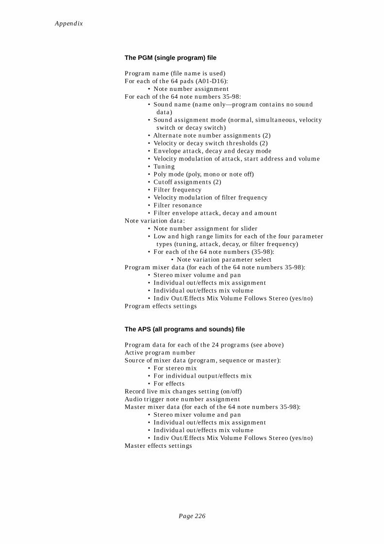
Page 226
Appendix
The PGM (single program) file
Program name (file name is used)For each of the 64 pads (A01-D16):
• Note number assignmentFor each of the 64 note numbers 35-98:
• Sound name (name only—program contains no sounddata)
• Sound assignment mode (normal, simultaneous, velocityswitch or decay switch)
• Alternate note number assignments (2)• Velocity or decay switch thresholds (2)• Envelope attack, decay and decay mode• Velocity modulation of attack, start address and volume• Tuning• Poly mode (poly, mono or note off)• Cutoff assignments (2)• Filter frequency• Velocity modulation of filter frequency• Filter resonance• Filter envelope attack, decay and amount
Note variation data:• Note number assignment for slider• Low and high range limits for each of the four parameter
types (tuning, attack, decay, or filter frequency)• For each of the 64 note numbers (35-98):
• Note variation parameter selectProgram mixer data (for each of the 64 note numbers 35-98):
• Stereo mixer volume and pan• Individual out/effects mix assignment• Individual out/effects mix volume• Indiv Out/Effects Mix Volume Follows Stereo (yes/no)
Program effects settings
The APS (all programs and sounds) file
Program data for each of the 24 programs (see above)Active program numberSource of mixer data (program, sequence or master):
• For stereo mix• For individual output/effects mix• For effects
Record live mix changes setting (on/off)Audio trigger note number assignmentMaster mixer data (for each of the 64 note numbers 35-98):
• Stereo mixer volume and pan• Individual out/effects mix assignment• Individual out/effects mix volume• Indiv Out/Effects Mix Volume Follows Stereo (yes/no)
Master effects settings
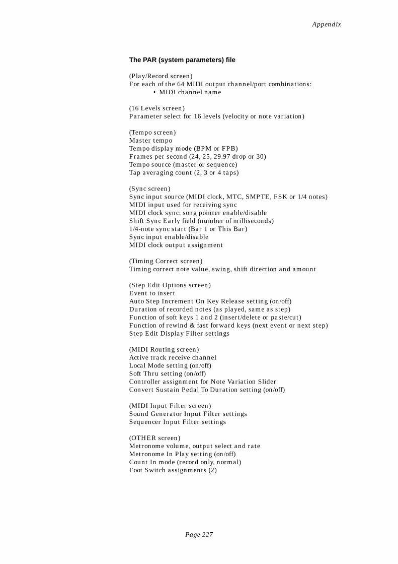
Page 227
Appendix
The PAR (system parameters) file
(Play/Record screen)For each of the 64 MIDI output channel/port combinations:
• MIDI channel name
(16 Levels screen)Parameter select for 16 levels (velocity or note variation)
(Tempo screen)Master tempoTempo display mode (BPM or FPB)Frames per second (24, 25, 29.97 drop or 30)Tempo source (master or sequence)Tap averaging count (2, 3 or 4 taps)
(Sync screen)Sync input source (MIDI clock, MTC, SMPTE, FSK or 1/4 notes)MIDI input used for receiving syncMIDI clock sync: song pointer enable/disableShift Sync Early field (number of milliseconds)1/4-note sync start (Bar 1 or This Bar)Sync input enable/disableMIDI clock output assignment
(Timing Correct screen)Timing correct note value, swing, shift direction and amount
(Step Edit Options screen)Event to insertAuto Step Increment On Key Release setting (on/off)Duration of recorded notes (as played, same as step)Function of soft keys 1 and 2 (insert/delete or paste/cut)Function of rewind & fast forward keys (next event or next step)Step Edit Display Filter settings
(MIDI Routing screen)Active track receive channelLocal Mode setting (on/off)Soft Thru setting (on/off)Controller assignment for Note Variation SliderConvert Sustain Pedal To Duration setting (on/off)
(MIDI Input Filter screen)Sound Generator Input Filter settingsSequencer Input Filter settings
(OTHER screen)Metronome volume, output select and rateMetronome In Play setting (on/off)Count In mode (record only, normal)Foot Switch assignments (2)
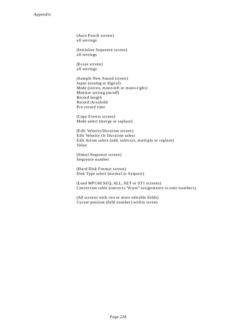
Page 228
Appendix
(Auto Punch screen)all settings
(Initialize Sequence screen)all settings
(Erase screen)all settings
(Sample New Sound screen)Input (analog or digital)Mode (stereo, mono-left or mono-right)Monitor setting (on/off)Record lengthRecord thresholdPre-record time
(Copy Events screen)Mode select (merge or replace)
(Edit Velocity/Duration screen)Edit Velocity Or Duration selectEdit Action select (add, subtract, multiply or replace)Value
(Simul Sequence screen)Sequence number
(Hard Disk Format screen)Disk Type select (normal or Syquest)
(Load MPC60 SEQ, ALL, SET or ST1 screens)Conversion table (converts “drum” assignments to note numbers)
(All screens with two or more editable fields)Cursor position (field number) within screen
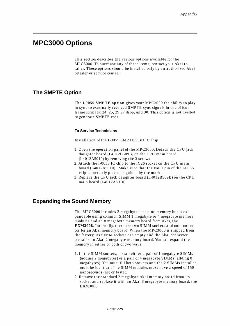
Page 229
Appendix
MPC3000 Options
This section describes the various options available for theMPC3000. To purchase any of these items, contact your Akai re-tailer. These options should be installed only by an authorized Akairetailer or service center.
The SMPTE Option
The I-0055 SMPTE option gives your MPC3000 the ability to playin sync to externally received SMPTE sync signals in one of fourframe formats: 24, 25, 29.97 drop, and 30. This option is not neededto generate SMPTE code.
To Service Technicians
Installation of the I-0055 SMPTE/EBU IC chip
1. Open the operation panel of the MPC3000; Detach the CPU jackdaughter board (L4012B509B) on the CPU main board(L4012A5010) by removing the 3 screws.
2. Attach the I-0055 IC chip to the IC26 socket on the CPU mainboard (L4012A5010). Make sure that the No. 1 pin of the I-0055chip is correctly placed as guided by the mark.
3. Replace the CPU jack daughter board (L4012B509B) on the CPUmain board (L4012A5010).
Expanding the Sound Memory
The MPC3000 includes 2 megabytes of sound memory but is ex-pandable using common SIMM 1 megabyte or 4 megabyte memorymodules and an 8 megabyte memory board from Akai, theEXM3008. Internally, there are two SIMM sockets and one connec-tor for an Akai memory board. When the MPC3000 is shipped fromthe factory, its SIMM sockets are empty and the Akai connectorcontains an Akai 2 megabyte memory board. You can expand thememory in either or both of two ways:
1. In the SIMM sockets, install either a pair of 1 megabyte SIMMs(adding 2 megabytes) or a pair of 4 megabyte SIMMs (adding 8megabytes). You must fill both sockets and the 2 SIMMs installedmust be identical. The SIMM modules must have a speed of 150nanoseconds (ns) or faster.
2. Remove the standard 2 megabyte Akai memory board from itssocket and replace it with an Akai 8 megabyte memory board, theEXM3008.
Page 230
Appendix
There are four possible combinations:
• Akai standard 2MB board + a pair of 1MB SIMMs: 4MB total• Akai standard 2MB board + a pair of 4MB SIMMs: 10MB total• Akai EXM3008 8MB board + a pair of 1MB SIMMs: 10MB total• Akai EXM3008 8MB board + a pair of 4MB SIMMs: 16MB total
Akai’s EXM3008 board can be purchased and installed at your Akairetailer.
The Video Output Option
The IB-CRT video option allows a video monitor to be connected tothe MPC3000, displaying the exact contents of the LCD screen at alltimes. This provides an easy way to view SMPTE and bar.beatlocation from across a room. The option adds a standard VGA videooutput connector to the rear panel of the MPC3000 to which astandard VGA monitor can be connected.

Page 231
Index
Index
Page 232
Index
+ and – keys 1716 LEVELS key 26Active Track, defined 35All Notes Off 216Analyzing Sequence message 223Answers to frequent questions 222Appendix 219Audio Trigger 161AUTO PUNCH key 60
Example 61Bar.beat.tick fields 30Basic Operations 13Choice Fields 17Command keys 16Copying a sequence 84Copying Bars 81Copying Events 82COUNT IN key 59Cursor, cursor keys 15Cutoff (cutting off one sound when another plays) 127Data entry
+ and – keys 17Choice fields 17Command keys 16Cursor 15Data entry control 16Data fields 15Numeric keypad 16
Data Entry Control 16Data fields 15Deleting Bars 80Digital sampling input 148Disk
Auto loading sounds and sequences 22Automatically loading files on power-up 182Contents of file types 225Copying a floppy 191Disk Files, overview 164DISK key 163Erasing files 173Formatting a floppy disk 186Formatting and Using a SCSI hard disk 188Loading a PAR file (system parameters) 182Loading a program file (and its sounds) 178Loading a sequence file 175Loading a sound file 177Loading ALL files (all sequences and songs) 177Loading an APS file (all programs and sounds) 178Loading an MPC60 version 1 or 2 SET or ST1 file 179Loading files 173Loading MPC60 version 1 or 2 ALL files 177Loading MPC60 version 1 or 2 sequence files 175
Page 233
Index
Partitions of hard disk 188Renaming files 173S1000/S3000 files, loading 184S1000/S3000 stereo files, loading 185Saving a PAR file (system parameters) 172Saving a sequence 166Saving a single program (and its sounds) 169Saving a single sound 168Saving an ALL file (all sequences and songs) 167Saving an APS file (all programs and sounds) 170Saving files 166
Drum Tracks 30, 35EDIT LOOP key 103Edit Loop, using as an undo function 104Edit Note Data (global editing of note events) 86Effects 145Envelope (volume) 125ERASE key 72Erasing notes in real time 72Erasing notes while stopped 72FAST FORWARD keys 40Filter Envelope 129Filter, dynamic 128Foot Switches 64Free Sequence Memory 64FULL LEVEL key 23Gain Switch (rear panel) 152Getting around on the MPC3000 15HELP key 18Hooking up your system 14Individual out/effects mixer 136Inserting Blank Bars 79Irregular timing 222Local Mode 210LOCATE key 41Looping, sequence 34MAIN SCREEN key 32Metronome settings 63MIDI
All notes off 216Assigning Pads to Note Numbers 208Feedback loop 211Implementation Charts 217Input Filter 213Local Mode 210MIDI key 207MIDI Routing 210Output Channel Assignment for tracks 36Receive Channel 210Soft Thru 210
MIDI Channels 30MIDI System-Exclusive Data, recording 70
Page 234
Index
MIDI Tracks 30, 35Mix Data, setting all channels at once 141Mix, automated 143Mixer source select 142MIXER/EFFECTS Key 133Mixers, text view 139Multichannel Sequence Recording 67Note Number Assignment, globally editing 89Note Number, defined 20Note Repeat 52Note Variation
16 LEVELS key 26AFTER key 26ASSIGN key 24Controlling from external MIDI controller 211Defined 24Globally editing 90Slider 24
Now field (current location counter) 37Numeric Keypad 16Options for MPC3000 229OTHER key 63OVERDUB key 39Overdub Mode, defined 39PAD BANK key 22Pad, defined 20PLAY key 39PLAY START key 39PLAY/RECORD keys 39Play/Record screen 32Poly Mode (poly, mono or note off) 126Programs
Active Program, defined 119Copying and Initializing 130Cutoff (cutting off one sound when another plays) 127Defined 21, 116Effects 145Filter envelope 129Filter, dynamic 128Graphic representation of 117How to create 118Individual out/effects mixer 136Mix data, text view 139Note Numbers 116Pad Banks 22Pad, defined 20Playing Simultaneous Sounds 120Poly mode (poly, mono or note off) 126PROGRAM/SOUNDS key 115Selecting 23Selecting the active program and assigning sounds 119Sound Assignment mode 120
Page 235
Index
Stereo Mixer 134Switching sounds depending on Envelope Decay 122The MIXER/EFFECTS Key 133Tuning 126Velocity modulation of attack, start address & volume 126Velocity Switching between sounds. 121Volume Envelope 125
Punching in and out 33, 39, 40Record 16 Channels 67RECORD key 39Record Level Control 152Record Ready mode 32Reversing sample data 156REWIND keys 40Sample data, editing 156Sampling a new sound 148Sampling, an example 152Sampling, balanced inputs 151Sampling, stereo 148SEQ EDIT key 77Sequence, defined 19Sequencer, using the MPC3000’s sounds and pads with another 224Sequences
Active Track, defined 35Bar.beat.tick fields 30Changing while playing 32Copying 84Copying bars 81Copying events 82Data Organization 30Defined 19Deleting 74Deleting all 74Deleting bars 80Drum Tracks 35Editing 71Editing note data (global editing of note events) 86Erasing 72Erasing notes in real time 72Erasing notes while stopped 72Globally editing drum note number assignment 89Globally editing velocity or duration data 87Initializing 75Inserting blank bars 79Looping 34MIDI Channels 30MIDI Tracks 30, 35Note Variation Data, globally editing 90Play/Record screen 32Program Number Assignment for tracks 37Punching in and out 33, 40Record all 16 MIDI channels 67
Page 236
Index
Record Ready mode 32Recording 29, 39Recording with multiple tracks, example 44Recording, example 42SEQ EDIT key 77Shift Timing 85Step Editing (visual editing) 92Step Recording 102Ticks 30Track, defined 19Transposing 105
Shift Timing 85Shift Timing (in Timing Correct) 50SIMUL SEQ key 62Soft Keys 17Soft Thru, MIDI 210Songs
An example of creating 112Converting a song into a long sequence 114Defined 19Overview 108SONG key 109Song Mode screen 109
Sound Module, using the MPC3000 as a 223Sounds
Defined 20Deleting all 160Digital sampling input 148Finding the Best Soft Start 156Gain Switch (rear panel) 152PROGRAM/SOUNDS key 147Record Level Control 152Renaming, copying and deleting 158Reversing sample data 156Sample data, editing 156Sampling a new sound 148Sampling, balanced inputs 151Sampling, stereo 148Soft end 154Soft start 154Sound memory expansion option 229Trigger from audio source 161Tuning 154Volume 154
STEP EDIT key 92Step Edit Options 99Step Edit, event types 95Step Edit, using 93Step Recording 102Stereo Mixer 134STOP key 39Sustain Pedal, converting to note durations 211
Page 237
Index
Swing 50Sync
1/4 note clicks 1981/4 note clicks, syncing to 2061/4-note clicks 195FSK24 195, 198FSK24, syncing to 204MIDI clock 194, 195MIDI clock, generating 199MIDI clock, syncing to 201MIDI time code 194, 197MIDI time code, syncing to 204Outputting sync 199SMPTE 194, 196SMPTE option 229SMPTE, generating 199SMPTE, syncing to 201Sync screen 194Turning sync input on and off 199
System Parameters, initializing 66System-Exclusive Data, recording 70Tap Averaging 55TAP TEMPO key 58Technical specifications 220Tempo
Adjusting 34, 53BPM/FPB 54BPM/FPB select 33Frames/second 54Source select (master or sequence) 34, 53Sync, external 193TAP TEMPO key 58Tap Tempo, Tap Averaging 55Tempo Changes, mid-sequence 56Tempo screen 53
TEMPO/SYNC key, sync functions 193Ticks 30Time Signature
Viewing 34Viewing and changing 77
Timing CorrectNote Repeat 52
TIMING CORRECT key 49Timing delays 222Track, defined 19, 30Tracks, muting 38Tracks, rearranging order of 78Tracks, soloing 38TRANSPOSE key 105Transposing in real time while playing 106Troubleshooting 222Tuning (program data) 126
Page 238
Index
Undo, using Edit Loop key 104Velocity modulation of attack, start address & volume 126Velocity or duration data, globally editing 87Video output option 230WAIT FOR KEY key 59[<<] and [>>] keys 40[<] and [>] keys 40
MIDI PRODUCTION CENTERSoftware version 3.1
Operator's Manual
WARNINGTo prevent fire or shock hazard, do notexpose this appliance to rain or moisture.
SOFTWARE UPDATE
New Features of Version 3.1
Saving and Loading Standard MIDI Files .................................................... 1
Loading Sample Files From Akai S1000/S3000
CD-ROMs or Hard Disks .............................................................................. 5
Connecting Multiple SCSI Devices, Making a SCSI
Device Active Without Recycling Power ................................................. 7
MIDI Machine Control .....................................................................................10
Sending MIDI Time Code In Real Time While Playing ............................12
MIDI Sample Dump ..........................................................................................13
Saving Program or APS Files Without Sounds,
Optional Overwriting of Sounds During Program
Save or Load.................................................................................................17
New Sound Edit Options— Delete Before Soft Start and
Delete After Soft End .................................................................................21
Improved Speed of Saving to Hard Disk ..................................................... 22
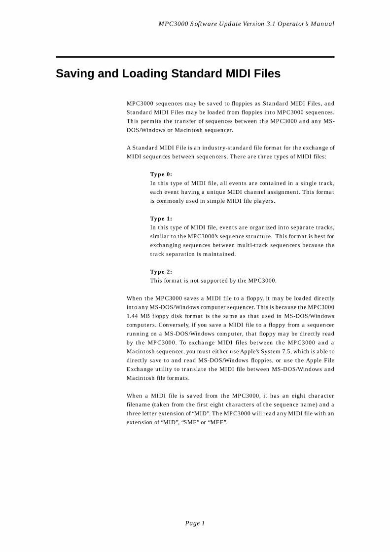
Page 1
MPC3000 Software Update Version 3.1 Operator’s Manual
Saving and Loading Standard MIDI Files
MPC3000 sequences may be saved to floppies as Standard MIDI Files, andStandard MIDI Files may be loaded from floppies into MPC3000 sequences.This permits the transfer of sequences between the MPC3000 and any MS-DOS/Windows or Macintosh sequencer.
A Standard MIDI File is an industry-standard file format for the exchange ofMIDI sequences between sequencers. There are three types of MIDI files:
Type 0:In this type of MIDI file, all events are contained in a single track,each event having a unique MIDI channel assignment. This formatis commonly used in simple MIDI file players.
Type 1:In this type of MIDI file, events are organized into separate tracks,similar to the MPC3000’s sequence structure. This format is best forexchanging sequences between multi-track sequencers because thetrack separation is maintained.
Type 2:This format is not supported by the MPC3000.
When the MPC3000 saves a MIDI file to a floppy, it may be loaded directlyinto any MS-DOS/Windows computer sequencer. This is because the MPC30001.44 MB floppy disk format is the same as that used in MS-DOS/Windowscomputers. Conversely, if you save a MIDI file to a floppy from a sequencerrunning on a MS-DOS/Windows computer, that floppy may be directly readby the MPC3000. To exchange MIDI files between the MPC3000 and aMacintosh sequencer, you must either use Apple’s System 7.5, which is able todirectly save to and read MS-DOS/Windows floppies, or use the Apple FileExchange utility to translate the MIDI file between MS-DOS/Windows andMacintosh file formats.
When a MIDI file is saved from the MPC3000, it has an eight characterfilename (taken from the first eight characters of the sequence name) and athree letter extension of “MID”. The MPC3000 will read any MIDI file with anextension of “MID”, “SMF” or “MFF”.
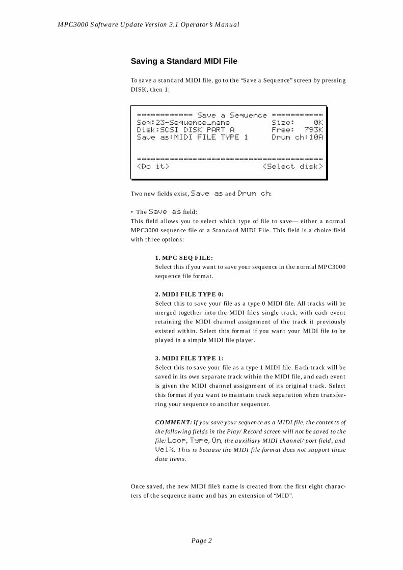
Page 2
MPC3000 Software Update Version 3.1 Operator’s Manual
Saving a Standard MIDI File
To save a standard MIDI file, go to the “Save a Sequence” screen by pressingDISK, then 1:
============ Save a Sequence ===========Seq:23-Sequence_name Size: 0KDisk:SCSI DISK PART A Free: 793KSave as:MIDI FILE TYPE 1 Drum ch:10A
========================================<Do it> <Select disk>
Two new fields exist, Save as and Drum ch:
• The Save as field:This field allows you to select which type of file to save— either a normalMPC3000 sequence file or a Standard MIDI File. This field is a choice fieldwith three options:
1. MPC SEQ FILE:Select this if you want to save your sequence in the normal MPC3000sequence file format.
2. MIDI FILE TYPE 0:Select this to save your file as a type 0 MIDI file. All tracks will bemerged together into the MIDI file’s single track, with each eventretaining the MIDI channel assignment of the track it previouslyexisted within. Select this format if you want your MIDI file to beplayed in a simple MIDI file player.
3. MIDI FILE TYPE 1:Select this to save your file as a type 1 MIDI file. Each track will besaved in its own separate track within the MIDI file, and each eventis given the MIDI channel assignment of its original track. Selectthis format if you want to maintain track separation when transfer-ring your sequence to another sequencer.
COMMENT: If you save your sequence as a MIDI file, the contents ofthe following fields in the Play/Record screen will not be saved to thefile: Loop, Type, On, the auxiliary MIDI channel/port field, andVel%. This is because the MIDI file format does not support thesedata items.
Once saved, the new MIDI file’s name is created from the first eight charac-ters of the sequence name and has an extension of “MID”.
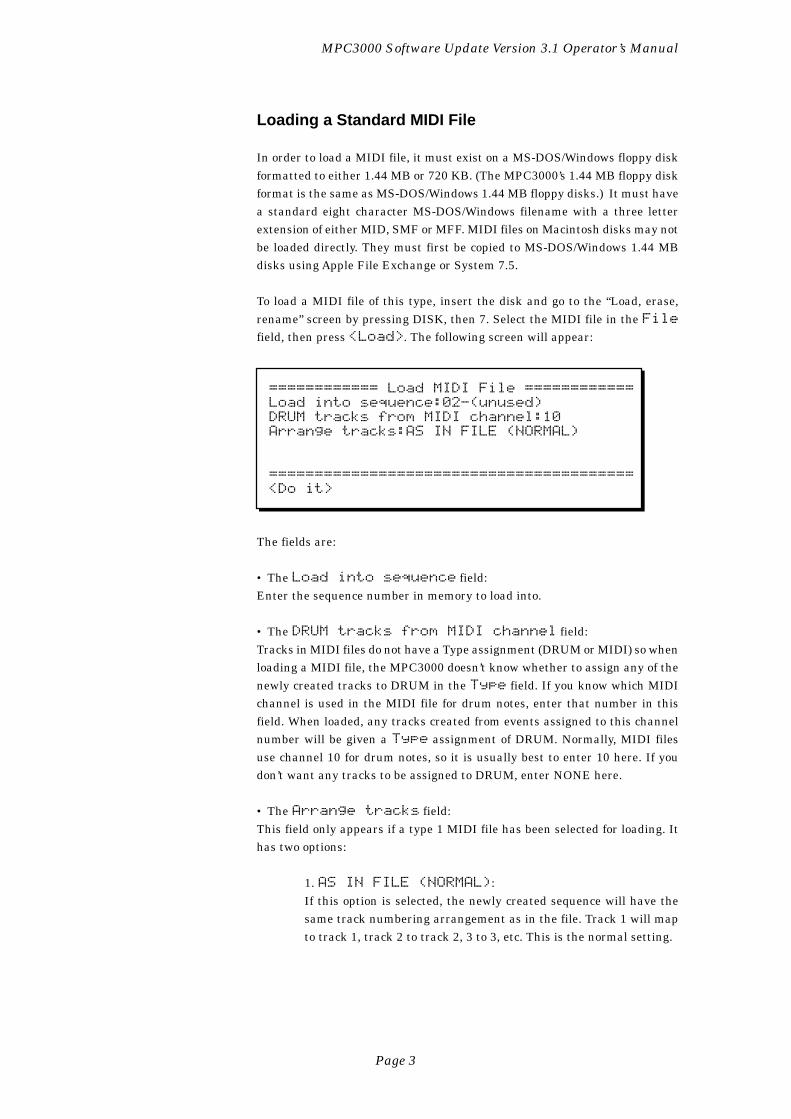
Page 3
MPC3000 Software Update Version 3.1 Operator’s Manual
Loading a Standard MIDI File
In order to load a MIDI file, it must exist on a MS-DOS/Windows floppy diskformatted to either 1.44 MB or 720 KB. (The MPC3000’s 1.44 MB floppy diskformat is the same as MS-DOS/Windows 1.44 MB floppy disks.) It must havea standard eight character MS-DOS/Windows filename with a three letterextension of either MID, SMF or MFF. MIDI files on Macintosh disks may notbe loaded directly. They must first be copied to MS-DOS/Windows 1.44 MBdisks using Apple File Exchange or System 7.5.
To load a MIDI file of this type, insert the disk and go to the “Load, erase,rename” screen by pressing DISK, then 7. Select the MIDI file in the Filefield, then press <Load>. The following screen will appear:
============ Load MIDI File ============Load into sequence:02-(unused)DRUM tracks from MIDI channel:10Arrange tracks:AS IN FILE (NORMAL)
========================================<Do it>
The fields are:
• The Load into sequence field:Enter the sequence number in memory to load into.
• The DRUM tracks from MIDI channel field:Tracks in MIDI files do not have a Type assignment (DRUM or MIDI) so whenloading a MIDI file, the MPC3000 doesn’t know whether to assign any of thenewly created tracks to DRUM in the Type field. If you know which MIDIchannel is used in the MIDI file for drum notes, enter that number in thisfield. When loaded, any tracks created from events assigned to this channelnumber will be given a Type assignment of DRUM. Normally, MIDI filesuse channel 10 for drum notes, so it is usually best to enter 10 here. If youdon’t want any tracks to be assigned to DRUM, enter NONE here.
• The Arrange tracks field:This field only appears if a type 1 MIDI file has been selected for loading. Ithas two options:
1. AS IN FILE (NORMAL):If this option is selected, the newly created sequence will have thesame track numbering arrangement as in the file. Track 1 will mapto track 1, track 2 to track 2, 3 to 3, etc. This is the normal setting.
Page 4
MPC3000 Software Update Version 3.1 Operator’s Manual
2. ONE PER MIDI OUTPUT:In this option is selected, one track is created for each channel/portassignment in use within the MIDI file, and all events are mapped totracks with the same channel/port assignment, regardless of theiroriginal track numbers. For example, if a MIDI file to be loaded con-tains events assigned to channel/port 1A, 6D, 7B and 2C, then theresulting sequence would contain four tracks assigned to these chan-nel/ports, and containing the events that had the same channel/portassignments in the MIDI file. This option will cause different trackscontaining the same channel/port assignments to be merged together,but allows MIDI files with more than 99 tracks to be loaded.
COMMENT: If a type 0 file is selected for loading, the message “(For-mat 0 file, will auto-map tracks)” appears in place of this field. Thisindicates that, as with the ONE PER MIDI OUTPUT selection, onetrack will be created for each channel/port assignment that exists inthe file’s single track.
To load the MIDI file, set the fields as desired then press <Do it>.
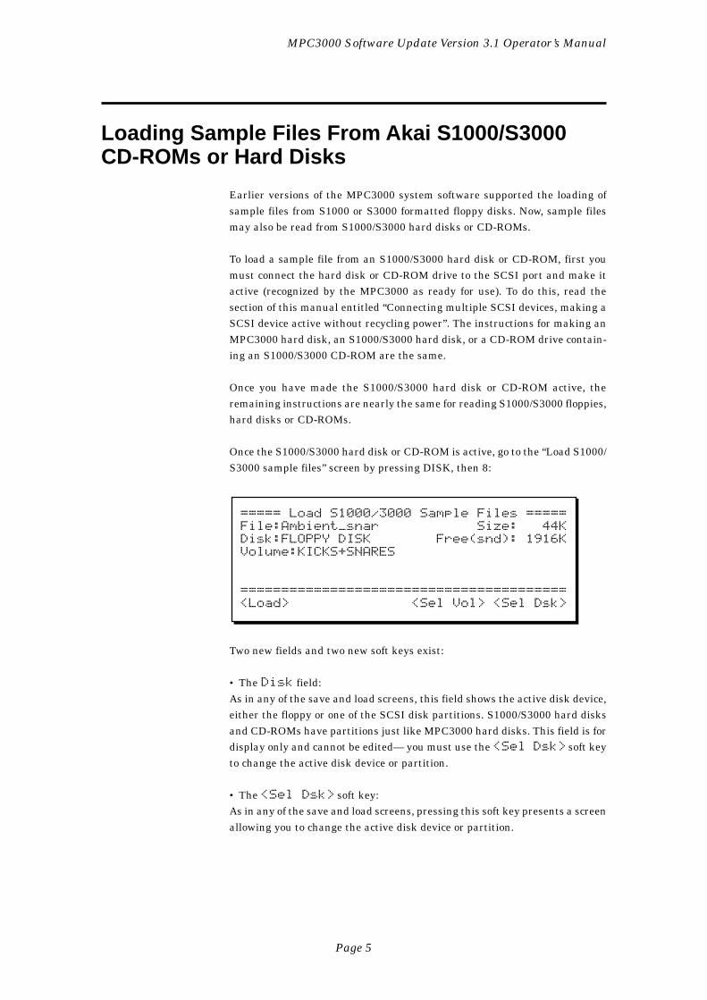
Page 5
MPC3000 Software Update Version 3.1 Operator’s Manual
Loading Sample Files From Akai S1000/S3000CD-ROMs or Hard Disks
Earlier versions of the MPC3000 system software supported the loading ofsample files from S1000 or S3000 formatted floppy disks. Now, sample filesmay also be read from S1000/S3000 hard disks or CD-ROMs.
To load a sample file from an S1000/S3000 hard disk or CD-ROM, first youmust connect the hard disk or CD-ROM drive to the SCSI port and make itactive (recognized by the MPC3000 as ready for use). To do this, read thesection of this manual entitled “Connecting multiple SCSI devices, making aSCSI device active without recycling power”. The instructions for making anMPC3000 hard disk, an S1000/S3000 hard disk, or a CD-ROM drive contain-ing an S1000/S3000 CD-ROM are the same.
Once you have made the S1000/S3000 hard disk or CD-ROM active, theremaining instructions are nearly the same for reading S1000/S3000 floppies,hard disks or CD-ROMs.
Once the S1000/S3000 hard disk or CD-ROM is active, go to the “Load S1000/S3000 sample files” screen by pressing DISK, then 8:
===== Load S1000/3000 Sample Files =====File:Ambient_snar Size: 44KDisk:FLOPPY DISK Free(snd): 1916KVolume:KICKS+SNARES
========================================<Load> <Sel Vol> <Sel Dsk>
Two new fields and two new soft keys exist:
• The Disk field:As in any of the save and load screens, this field shows the active disk device,either the floppy or one of the SCSI disk partitions. S1000/S3000 hard disksand CD-ROMs have partitions just like MPC3000 hard disks. This field is fordisplay only and cannot be edited— you must use the <Sel Dsk> soft keyto change the active disk device or partition.
• The <Sel Dsk> soft key:As in any of the save and load screens, pressing this soft key presents a screenallowing you to change the active disk device or partition.
Page 6
MPC3000 Software Update Version 3.1 Operator’s Manual
• The Volume field:On S1000 or S3000 hard disks or CD-ROMs, each partition may contain up to100 volumes, in which the actual files are contained. Volumes act as directo-ries— files are contained within volumes, and volumes are contained withinpartitions. This field displays the active volume and only appears if a SCSIdisk partition, not the floppy, is selected in the Disk field. It is for displayonly and cannot be edited. To change the active volume, you must press <SelVol>.
• The <Sel Vol> soft key:Pressing this soft key presents a screen that allows you to change the activevolume of the S1000/S3000 hard disk or CD-ROM. This field appears only if aS1000 or S3000 hard disk or CD-ROM is active and one of the disk partitionsis currently selected in the Disk field above.
Other than the above changes, this screen operates as in previous systemsoftware versions.
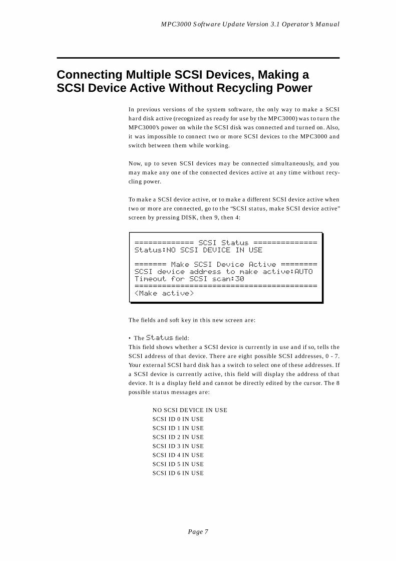
Page 7
MPC3000 Software Update Version 3.1 Operator’s Manual
Connecting Multiple SCSI Devices, Making aSCSI Device Active Without Recycling Power
In previous versions of the system software, the only way to make a SCSIhard disk active (recognized as ready for use by the MPC3000) was to turn theMPC3000’s power on while the SCSI disk was connected and turned on. Also,it was impossible to connect two or more SCSI devices to the MPC3000 andswitch between them while working.
Now, up to seven SCSI devices may be connected simultaneously, and youmay make any one of the connected devices active at any time without recy-cling power.
To make a SCSI device active, or to make a different SCSI device active whentwo or more are connected, go to the “SCSI status, make SCSI device active”screen by pressing DISK, then 9, then 4:
============= SCSI Status ==============Status:NO SCSI DEVICE IN USE
======= Make SCSI Device Active ========SCSI device address to make active:AUTOTimeout for SCSI scan:30========================================<Make active>
The fields and soft key in this new screen are:
• The Status field:This field shows whether a SCSI device is currently in use and if so, tells theSCSI address of that device. There are eight possible SCSI addresses, 0 - 7.Your external SCSI hard disk has a switch to select one of these addresses. Ifa SCSI device is currently active, this field will display the address of thatdevice. It is a display field and cannot be directly edited by the cursor. The 8possible status messages are:
NO SCSI DEVICE IN USESCSI ID 0 IN USESCSI ID 1 IN USESCSI ID 2 IN USESCSI ID 3 IN USESCSI ID 4 IN USESCSI ID 5 IN USESCSI ID 6 IN USE
Page 8
MPC3000 Software Update Version 3.1 Operator’s Manual
Only addresses 0 - 6 may be used for external SCSI devices. Address 7 cannotbe used because it is the address of the MPC3000.
• The SCSI device address to make active field:This field determines which SCSI address will be made active when the poweris turned on or when <Make active> is pressed. It is a choice field withthe following options:
AUTO (scan for lowest addressed SCSI device)0 (scan for SCSI device address 0)1 (scan for SCSI device address 1)2 (scan for SCSI device address 2)3 (scan for SCSI device address 3)4 (scan for SCSI device address 4)5 (scan for SCSI device address 5)6 (scan for SCSI device address 6)
If only one SCSI device is connected to the SCSI port, select AUTO. Then,when <Make active> is pressed or when power is turned on, the singledevice will be made active regardless of its address setting, 0 - 6. (If two ormore devices are connected when the “AUTO” scan is done, only the devicewith the lowest address will be made active.) In operating system 3.08 orearlier, the MPC3000 always performed an “AUTO” scan at power-on.
It is only necessary to enter a specific SCSI address (0 - 6) in this field if morethan one SCSI device is connected to the SCSI port. In this case, enter thespecific address of the device you want to make active (0 - 6). Then, when<Make active> is pressed or when power is turned on, the SCSI portwill be scanned and only the device with the specified address will be madeactive.
• The Timeout for SCSI scan field:This field has the same function as the Power-on SCSI searchdelay field, used in operating system version 3.08 or earlier. When <Makeactive> is pressed or when power is turned on, the MPC3000 continu-ously scans the SCSI port for a device to make active. If it doesn’t find a de-vice, it continues its scan for the number of seconds entered in this field, thendisplays an error message. Since the scan is usually done at power-on whenboth the MPC3000 and the hard disk are turned on simultaneously, it is im-portant to give enough waiting time for the hard disk to spin up to operatingspeed. Most hard disks come up to operating speed within about 20 seconds,so the default setting here is 30 seconds. If the MPC3000 is not recognizingyour hard disk when both devices are powered on simultaneously, try a longerscan time in this field.
COMMENT: If you aren’t using a hard disk and you’d like to elimi-nate this power-on scan time, select 0 in this field.
Page 9
MPC3000 Software Update Version 3.1 Operator’s Manual
• The <Make active> soft key:Press this soft key to make the connected SCSI hard disk active. Wheneverthe MPC3000 is turned on, it automatically performs the same function aspressing this soft key. In either case, the Status field will subsequentlyshow that the hard disk is active.
Hard Disk Format now allows selection of SCSI address
When formatting a SCSI hard disk, it is now possible to specify the SCSIaddress of the hard disk to be formatted. Press DISK, 9, then 3 to go to theFormat Hard Disk screen:
=========== Format Hard Disk ===========SCSI address:AUTO
Formatting will erase all existing dataand divide the disk into 'partitions' ofless than 30 megabytes each.========================================<Next screen>
The new field, SCSI address, has the same function as the SCSIdevice to make active field described above— it contains theaddress (0 - 6) of the external SCSI hard disk to be formatted. If the only SCSIdevice connected is the hard disk to be formatted, enter AUTO here and theMPC3000 will automatically determine its SCSI address. (It is strongly rec-ommended to have no other SCSI devices connected during a hard disk for-mat.) If more than one SCSI device is connected, enter here the SCSI addressof the hard disk drive to be formatted (0 - 6).
Page 10
MPC3000 Software Update Version 3.1 Operator’s Manual
MIDI Machine Control
MIDI Machine Control (abbreviated “MMC”) is a standard system of commu-nication over MIDI that allows the MPC3000 to remotely control the trans-port of an MMC-compatible audio or video recorder. By using MIDI MachineControl, the MPC3000 can remotely play, record, stop or reposition an exter-nal recorder.
To use MIDI Machine Control, press MIDI, then 4, and the MIDI MachineControl screen will appear:
========= MIDI Machine Control =========Send MMC:OFF MIDI out:A
(Shortcut to toggle MMC on or off fromPlay/Record or Song screens: hold STOP& press PLAY.)========================================
To turn MMC on:
1. Connect a MIDI cable from one of the MPC3000’s MIDI outputs tothe external recorder’s MIDI input.
2. Set the MMC field in the above screen to ON.
3. Set the MIDI out field in the above screen to the same MIDIoutput port to which you connected the external recorder.
4. Set the external recorder to respond to MMC commands. (The ex-ternal recorder must be MMC-compatible.)
While MMC is on, the keys in the Play/Record section of the front panel havedifferent functions:
PLAY: This does not play the MPC3000 sequencer. Instead, it sendsan MMC “deferred play” command to the external recorder, causingit to play.
STOP: This does not stop the MPC3000 sequencer. Instead, it sendsan MMC “stop” command to the external recorder.
PLAY START: This does not play the MPC3000 sequencer. Instead,it sends an MMC “Locate (to start)” command, followed by a “de-ferred play” command, causing it to play from the start of the record-ing.
Page 11
MPC3000 Software Update Version 3.1 Operator’s Manual
“<<”, “<”, LOCATE, “>”, and “>>”: In addition to their normalMPC3000 functions, these keys cause MMC “Locate” commands tobe sent out, repositioning the external recorder.
RECORD + PLAY pressed together: This does not enter recordmode on the MPC3000’s sequencer. Instead, it sends an MMC “Recordstrobe” command to the external recorder, causing it to enter recordmode.
Whenever an MMC command is sent, the bottom line of the screen brieflydisplays a message indicating that the command was sent.
MMC is most useful if the MPC3000 is also set to respond to SMPTE or MIDITime Code from the external recorder. This allows the MPC3000 not only toremotely control the external recorder’s transport functions, but also for bothdevices to play in sync. (To learn how to set the MPC3000 to receive incomingSMPTE or MIDI Time Code sync, read the chapter of the operator’s manual:“Syncing to tape and other devices”.)
If both MMC is on and the MPC3000 is receiving SMPTE or MTC sync fromthe external recorder, the PLAY, STOP and PLAY START keys act as follows:
PLAY: When pressed, the external recorder starts playing, causingits sync signal to be sent. When the MPC3000 receives the sync sig-nal, it starts playing in sync.
STOP: When pressed, the external recorder stops playing, causingits outgoing sync signal to stop. When the MPC3000 stops receivingsync, it stops playing.
PLAY START: When pressed, the external recorder repositions tothe start of the song and starts playing, causing its sync signal to besent. When the MPC3000 receives the sync signal, it starts playingin sync.
When using MMC, it is useful to quickly turn MMC on or off. For example,you may want to quickly turn MMC off in order to hear the MPC3000 playalone, then turn it back on in order to play both devices together. As the MMCscreen shows, a shortcut has been provided for this purpose: from the Play/Record or Song screens, hold the STOP key and press PLAY.
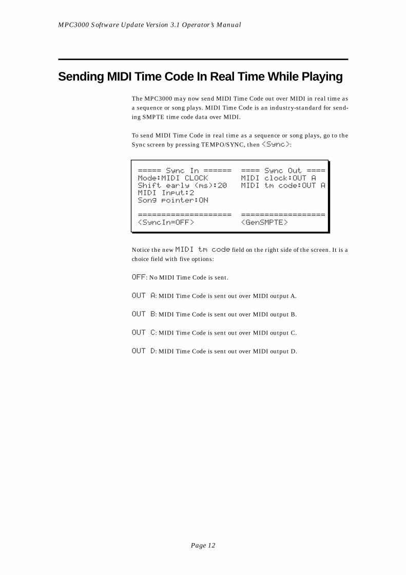
Page 12
MPC3000 Software Update Version 3.1 Operator’s Manual
Sending MIDI Time Code In Real Time While Playing
The MPC3000 may now send MIDI Time Code out over MIDI in real time asa sequence or song plays. MIDI Time Code is an industry-standard for send-ing SMPTE time code data over MIDI.
To send MIDI Time Code in real time as a sequence or song plays, go to theSync screen by pressing TEMPO/SYNC, then <Sync>:
===== Sync In ====== ==== Sync Out ====Mode:MIDI CLOCK MIDI clock:OUT AShift early (ms):20 MIDI tm code:OUT AMIDI Input:2Song pointer:ON
==================== ==================<SyncIn=OFF> <GenSMPTE>
Notice the new MIDI tm code field on the right side of the screen. It is achoice field with five options:
OFF: No MIDI Time Code is sent.
OUT A: MIDI Time Code is sent out over MIDI output A.
OUT B: MIDI Time Code is sent out over MIDI output B.
OUT C: MIDI Time Code is sent out over MIDI output C.
OUT D: MIDI Time Code is sent out over MIDI output D.
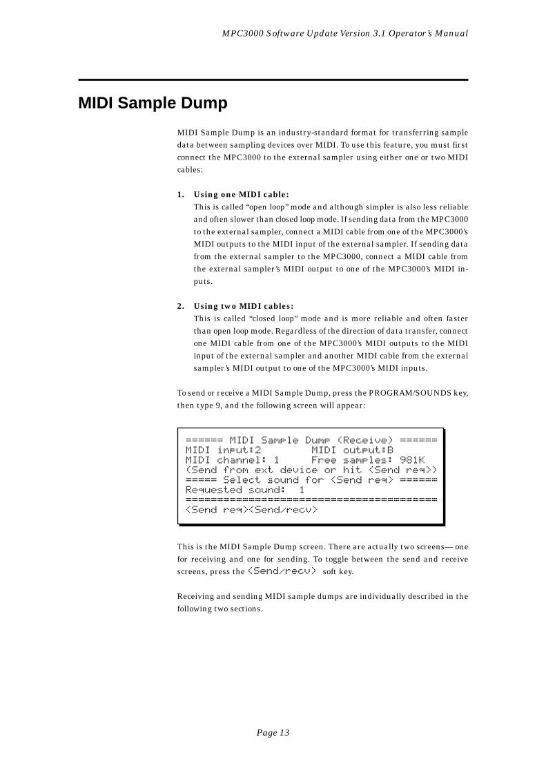
Page 13
MPC3000 Software Update Version 3.1 Operator’s Manual
MIDI Sample Dump
MIDI Sample Dump is an industry-standard format for transferring sampledata between sampling devices over MIDI. To use this feature, you must firstconnect the MPC3000 to the external sampler using either one or two MIDIcables:
1. Using one MIDI cable:This is called “open loop” mode and although simpler is also less reliableand often slower than closed loop mode. If sending data from the MPC3000to the external sampler, connect a MIDI cable from one of the MPC3000’sMIDI outputs to the MIDI input of the external sampler. If sending datafrom the external sampler to the MPC3000, connect a MIDI cable fromthe external sampler’s MIDI output to one of the MPC3000’s MIDI in-puts.
2. Using two MIDI cables:This is called “closed loop” mode and is more reliable and often fasterthan open loop mode. Regardless of the direction of data transfer, connectone MIDI cable from one of the MPC3000’s MIDI outputs to the MIDIinput of the external sampler and another MIDI cable from the externalsampler’s MIDI output to one of the MPC3000’s MIDI inputs.
To send or receive a MIDI Sample Dump, press the PROGRAM/SOUNDS key,then type 9, and the following screen will appear:
====== MIDI Sample Dump (Receive) ======MIDI input:2 MIDI output:BMIDI channel: 1 Free samples: 981K(Send from ext device or hit <Send req>)===== Select sound for <Send req> ======Requested sound: 1========================================<Send req><Send/recv>
This is the MIDI Sample Dump screen. There are actually two screens— onefor receiving and one for sending. To toggle between the send and receivescreens, press the <Send/recv> soft key.
Receiving and sending MIDI sample dumps are individually described in thefollowing two sections.
Page 14
MPC3000 Software Update Version 3.1 Operator’s Manual
Receiving a MIDI sample dump from an external sampler
To receive a MIDI Sample Dump, make sure that the receive screen is show-ing. If not, press <Send/recv>. The screen fields and soft keys are de-scribed below:
• The MIDI input field:This is the MIDI input jack number (1 or 2) through which the sound data willbe received. Set this field to the number of the MIDI input jack you used toconnect to the external sampler.
• The MIDI output field:This is the MIDI output jack (A, B, C or D) through which the sound data willbe sent. Set this field to the MIDI output jack you used to connect to theexternal sampler.
• The MIDI channel field:Enter here the same MIDI channel that the external sampler is set to trans-fer on.
• The Free samples field:This field is not changeable— it displays the amount of memory, in kilosamples,that is currently available to load new sounds into. This number should beexactly double the number of free kilobytes, shown in the “Load, erase, re-name file” screen.
• The Requested sound field:This field is used only if you are using “closed loop” mode (two MIDI cables).Enter the number of the sound (of the sounds currently loaded in the externalsampler) that you want to receive.
• The <Send req> soft key:This soft key is used only if you are using “closed loop” mode (two MIDI cables).When pressed, the MPC3000 sends out a “dump request” message to the ex-ternal sampler, tell it to start sending the sound number entered in the Re-quested sound field.
• The <Send/recv> soft key:Pressing this soft key toggles between the send and receive screens.
You may start the sample dump in one of two ways:
1. At the external sampler.While the MPC3000’s receive screen is showing, it stands ready to re-ceive a sample dump. Initiate the transfer at the external sampler.
2. Send a “dump request” to the external sampler.This method may only be used if the two devices are connected using“closed loop” mode (two MIDI cables). First, set the Requested sound
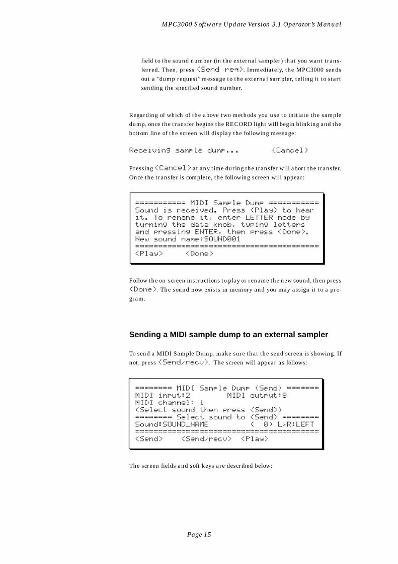
Page 15
MPC3000 Software Update Version 3.1 Operator’s Manual
field to the sound number (in the external sampler) that you want trans-ferred. Then, press <Send req>. Immediately, the MPC3000 sendsout a “dump request” message to the external sampler, telling it to startsending the specified sound number.
Regarding of which of the above two methods you use to initiate the sampledump, once the transfer begins the RECORD light will begin blinking and thebottom line of the screen will display the following message:
Receiving sample dump... <Cancel>
Pressing <Cancel> at any time during the transfer will abort the transfer.Once the transfer is complete, the following screen will appear:
=========== MIDI Sample Dump ===========Sound is received. Press <Play> to hearit. To rename it, enter LETTER mode byturning the data knob, typing lettersand pressing ENTER, then press <Done>.New sound name:SOUND001========================================<Play> <Done>
Follow the on-screen instructions to play or rename the new sound, then press<Done>. The sound now exists in memory and you may assign it to a pro-gram.
Sending a MIDI sample dump to an external sampler
To send a MIDI Sample Dump, make sure that the send screen is showing. Ifnot, press <Send/recv>. The screen will appear as follows:
======== MIDI Sample Dump (Send) =======MIDI input:2 MIDI output:BMIDI channel: 1(Select sound then press <Send>)======== Select sound to <Send> ========Sound:SOUND_NAME ( 0) L/R:LEFT========================================<Send> <Send/recv> <Play>
The screen fields and soft keys are described below:
Page 16
MPC3000 Software Update Version 3.1 Operator’s Manual
• The MIDI input, MIDI output, and MIDI channel fields,and the <Send/recv> soft key:These fields and soft key operate exactly as in the receive screen described inthe previous section.
• The Sound field:In this choice field, select the sound to be sent from an alphabetical list ofsounds in memory. To the right of this field is the selected sound’s numberwithin the list of sounds.
If the selected sound is stereo, an additional field, L/R, will appear furtherto the right. Because MIDI Sample Dump may only transfer mono sounds,you must select in this field to send either the LEFT or RIGHT side of thestereo sound.
• The <Send> soft key:Pressing this soft key will cause the MPC3000 to start sending the soundselected in the Sound field.
• The <Play> soft key:Press this soft key to hear the sound selected in the Sound field.
You may start the sample dump in one of two ways:
1. Set the Sound field to the sound you want to transfer, then press<Send>. Immediately, the MPC3000 starts sending the sample data.
2. Send a “dump request” from the external sampler.This method is possible only if “closed loop” mode (two MIDI cables) is inuse. When the MPC3000’s send screen is showing, it stands ready to sendsample data in response to receiving a “dump request” message. Do therequired procedure in order to send the dump request message from theexternal sampler.
Regarding of which of the above two methods you use to initiate the sampledump, once the transfer begins the PLAY light will start blinking and thebottom line of the screen will display the following message:
Sending sample dump... <Cancel>
Pressing <Cancel> at any time during the transfer will abort the transfer.Once the transfer is complete, the bottom line of the screen will return tonormal.
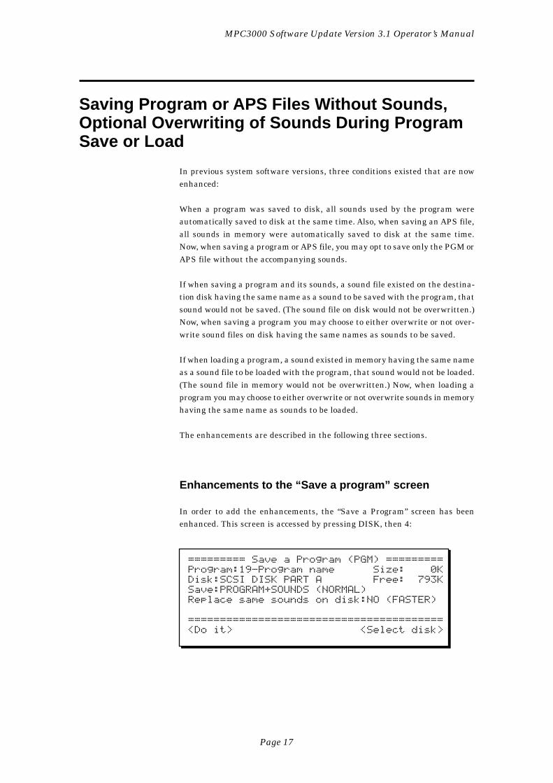
Page 17
MPC3000 Software Update Version 3.1 Operator’s Manual
Saving Program or APS Files Without Sounds,Optional Overwriting of Sounds During ProgramSave or Load
In previous system software versions, three conditions existed that are nowenhanced:
When a program was saved to disk, all sounds used by the program wereautomatically saved to disk at the same time. Also, when saving an APS file,all sounds in memory were automatically saved to disk at the same time.Now, when saving a program or APS file, you may opt to save only the PGM orAPS file without the accompanying sounds.
If when saving a program and its sounds, a sound file existed on the destina-tion disk having the same name as a sound to be saved with the program, thatsound would not be saved. (The sound file on disk would not be overwritten.)Now, when saving a program you may choose to either overwrite or not over-write sound files on disk having the same names as sounds to be saved.
If when loading a program, a sound existed in memory having the same nameas a sound file to be loaded with the program, that sound would not be loaded.(The sound file in memory would not be overwritten.) Now, when loading aprogram you may choose to either overwrite or not overwrite sounds in memoryhaving the same name as sounds to be loaded.
The enhancements are described in the following three sections.
Enhancements to the “Save a program” screen
In order to add the enhancements, the “Save a Program” screen has beenenhanced. This screen is accessed by pressing DISK, then 4:
========= Save a Program (PGM) =========Program:19-Program name Size: 0KDisk:SCSI DISK PART A Free: 793KSave:PROGRAM+SOUNDS (NORMAL)Replace same sounds on disk:NO (FASTER)
========================================<Do it> <Select disk>
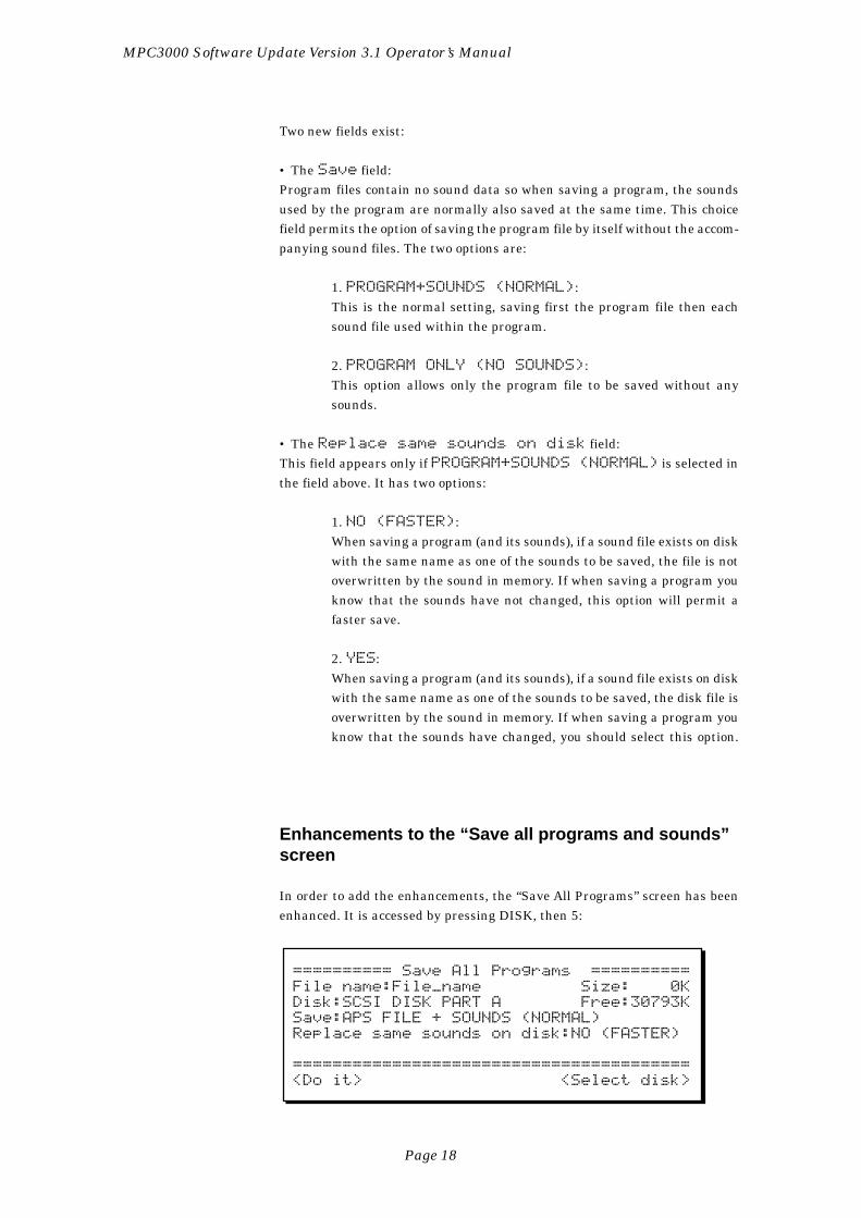
Page 18
MPC3000 Software Update Version 3.1 Operator’s Manual
Two new fields exist:
• The Save field:Program files contain no sound data so when saving a program, the soundsused by the program are normally also saved at the same time. This choicefield permits the option of saving the program file by itself without the accom-panying sound files. The two options are:
1. PROGRAM+SOUNDS (NORMAL):This is the normal setting, saving first the program file then eachsound file used within the program.
2. PROGRAM ONLY (NO SOUNDS):This option allows only the program file to be saved without anysounds.
• The Replace same sounds on disk field:This field appears only if PROGRAM+SOUNDS (NORMAL) is selected inthe field above. It has two options:
1. NO (FASTER):When saving a program (and its sounds), if a sound file exists on diskwith the same name as one of the sounds to be saved, the file is notoverwritten by the sound in memory. If when saving a program youknow that the sounds have not changed, this option will permit afaster save.
2. YES:When saving a program (and its sounds), if a sound file exists on diskwith the same name as one of the sounds to be saved, the disk file isoverwritten by the sound in memory. If when saving a program youknow that the sounds have changed, you should select this option.
Enhancements to the “Save all programs and sounds”screen
In order to add the enhancements, the “Save All Programs” screen has beenenhanced. It is accessed by pressing DISK, then 5:
========== Save All Programs ==========File name:File_name Size: 0KDisk:SCSI DISK PART A Free:30793KSave:APS FILE + SOUNDS (NORMAL)Replace same sounds on disk:NO (FASTER)
========================================<Do it> <Select disk>
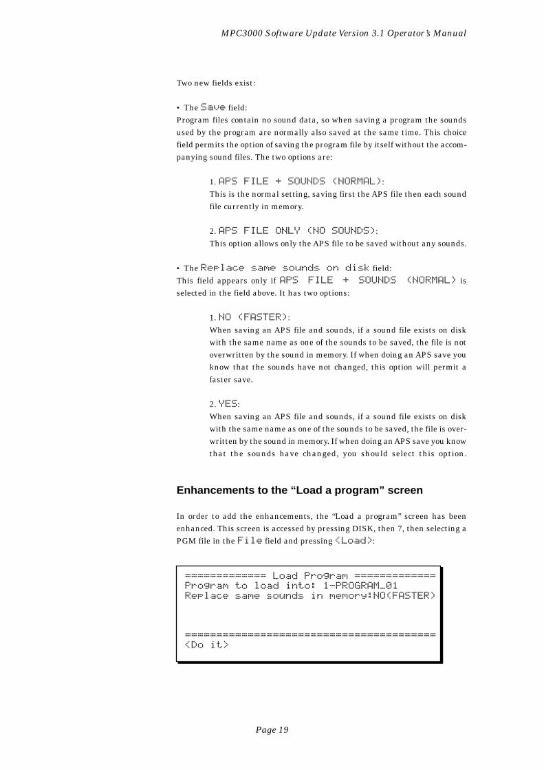
Page 19
MPC3000 Software Update Version 3.1 Operator’s Manual
Two new fields exist:
• The Save field:Program files contain no sound data, so when saving a program the soundsused by the program are normally also saved at the same time. This choicefield permits the option of saving the program file by itself without the accom-panying sound files. The two options are:
1. APS FILE + SOUNDS (NORMAL):This is the normal setting, saving first the APS file then each soundfile currently in memory.
2. APS FILE ONLY (NO SOUNDS):This option allows only the APS file to be saved without any sounds.
• The Replace same sounds on disk field:This field appears only if APS FILE + SOUNDS (NORMAL) isselected in the field above. It has two options:
1. NO (FASTER):When saving an APS file and sounds, if a sound file exists on diskwith the same name as one of the sounds to be saved, the file is notoverwritten by the sound in memory. If when doing an APS save youknow that the sounds have not changed, this option will permit afaster save.
2. YES:When saving an APS file and sounds, if a sound file exists on diskwith the same name as one of the sounds to be saved, the file is over-written by the sound in memory. If when doing an APS save you knowthat the sounds have changed, you should select this option.
Enhancements to the “Load a program” screen
In order to add the enhancements, the “Load a program” screen has beenenhanced. This screen is accessed by pressing DISK, then 7, then selecting aPGM file in the File field and pressing <Load>:
============= Load Program =============Program to load into: 1-PROGRAM_01Replace same sounds in memory:NO(FASTER)
========================================<Do it>
Page 20
MPC3000 Software Update Version 3.1 Operator’s Manual
A new field exists:
• The Replace same sounds in memory field:This choice field has two options:
1. NO(FASTER):When loading a program (and its sounds), if a sound file exists inmemory with the same name as one of the sounds to be loaded, thesound is not overwritten by the sound on disk, and the program willuse the sound of the same name already in memory. If you don’t usu-ally use different sound files with the same name in your sound li-brary, choose this option because it will enable faster loading.
2. YES:When loading a program (and its sounds), if a sound file exists inmemory with the same name as one of the sounds to be loaded, thesound is overwritten by the sound on disk. If you often use differentsound files with the same name in your sound library, choose thisoption to insure that the correct sound is always loaded with theprogram.
COMMENT: If you select YES and you overwrite a sound in memory,this may alter the sound of another program in memory that uses thesame sound. To avoid confusion, always try to avoid different soundfiles in your library with the same name.
Page 21
MPC3000 Software Update Version 3.1 Operator’s Manual
New Sound Edit Options— Delete Before SoftStart and Delete After Soft End
In previous system software versions, the Edit a Sound screen enabled thedeletion of any portion of a sound by setting the beginning and end of a “zone”,then deleting it. However, this was cumbersome for performing the most com-mon deletion: removing the unused portion of a sound before the soft startand after the soft end.
Now, the Do field in the Edit a Sound screen contains two new editing op-tions:
DEL BEFR SOFT ST (delete the area before the soft start)
DEL AFTR SFT END (delete the area after the soft end)
Page 22
MPC3000 Software Update Version 3.1 Operator’s Manual
Improved Speed of Saving to Hard Disk
In previous system software versions, saving to hard disk was slow. In thisversion, the speed of saving to hard disk has been greatly improved.


AKAI ELECTRIC CO., LTD.Electronic Musical Instrument Div.
940912 Imprimé au Japan


![Netex learningMaker | Author Manual v3.0 [En]](https://static.fdocuments.in/doc/165x107/541608ae8d7f722f6c8b4918/netex-learningmaker-author-manual-v30-en.jpg)