MP48 Dual Fuel System Installation Manual - Digitronic · - Diesel Pressure sensor with analog...
26
MP48 Dual Fuel System Installation Manual
-
Upload
doannguyet -
Category
Documents
-
view
216 -
download
1
Transcript of MP48 Dual Fuel System Installation Manual - Digitronic · - Diesel Pressure sensor with analog...

MP48 Dual Fuel System
Installation Manual

INDEX
1. Introduction
2. Vehicle Characteristics
3. Component Description
4. Connections
5. Installation
2. Vehicle Characteristics
- Diesel Engine with 12V Electric system
- Diesel Engine with common rail injection system
- Diesel Pressure sensor with analog signal type
- Accelerator pedal with linear signal (0 to 5V or 0 to 10V)
The Digitronic Dual Fuel System can be fitted if the engine is:
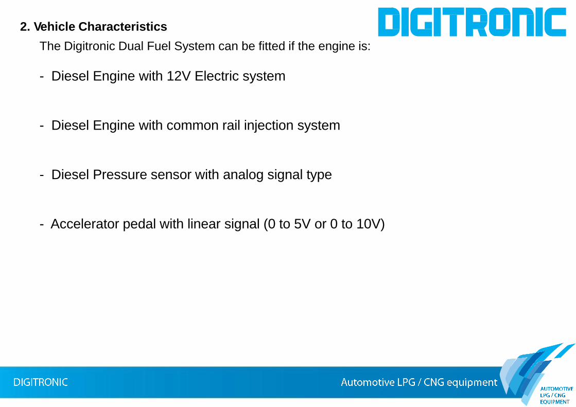
MP48DF Dual Fuel System
3.1
3.1: Accessory Bag
3.2: Switch
Code AEB119B
3.3: Dual Fuel System ECU
Code MP48 DF
3.4: Main Harness
Code 612998000
3.5: Exhaust Temperature Sensor
Code 620500172
3.6: Gas Pres & Temp Sensor Kit
Code 620500174
3.7: MAP sensor Kit
Code 620500173
3. Component Description
3.2
3.33.4
3.5
3.6 3.7

Bill of Material
Pos. Description QTY
1 Fuse Box Sealed 1
2 Fuse 15° series ATU 1
3 Ring Terminal 6,3x0,8 for wire section 0,5mm2 to 1,5mm2 3
Accessory for battery and ground connection (ring terminals) and System protection (fuse)
3.1 Accessory Bag
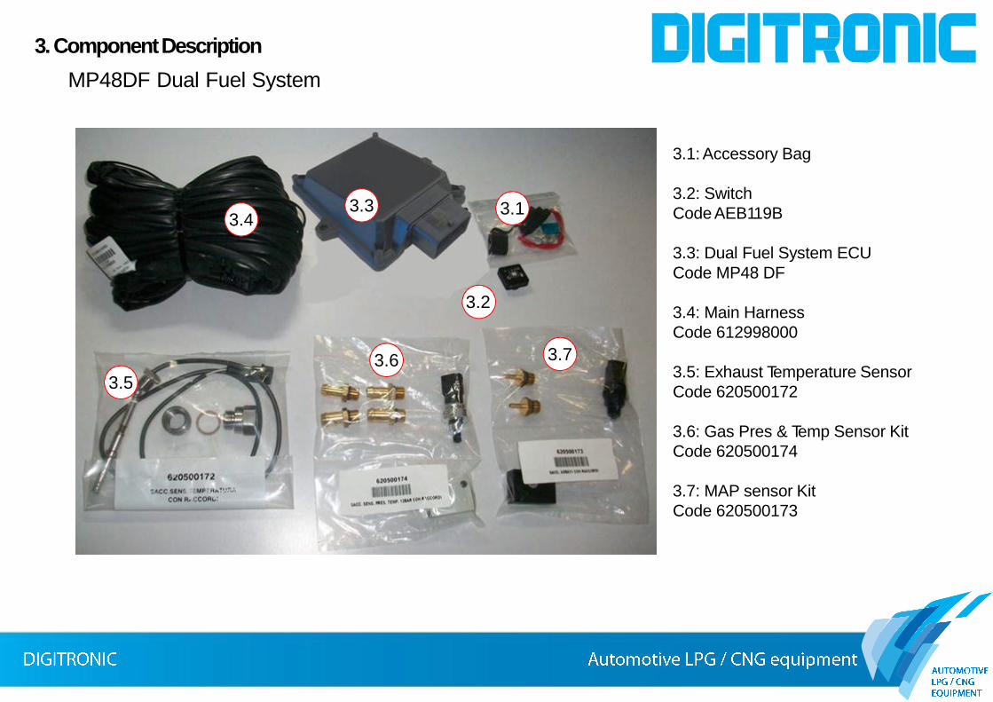
Switch and leds Description
Pos Description
1 Yellow Led – Fix ON, Diesel mode, when flashing Diesel mode for FAP regeneration
2 Button – for fuel type selection
3 Green Led – Fix ON, Dual fuel Mode, when flashing diesel mode but ready to pass on Dual Fuel
4 Red Led – Fix ON, alternative fuel reserve indication
5 4 Green Leds – In quarters, alternative fuel level indication
fBuzzer Build inside the Switch – if blinking quickly with the leds 3, 4 and 5 it indicates the system switched back to Diesel mode for
alternative fuel tank empty; if blinking slowly with the led 3 indicates there is some error in the Dual Fuel System
2 13
4 5 f
3.2 Switch code AEB119B
3.2.1 AEB119B Description
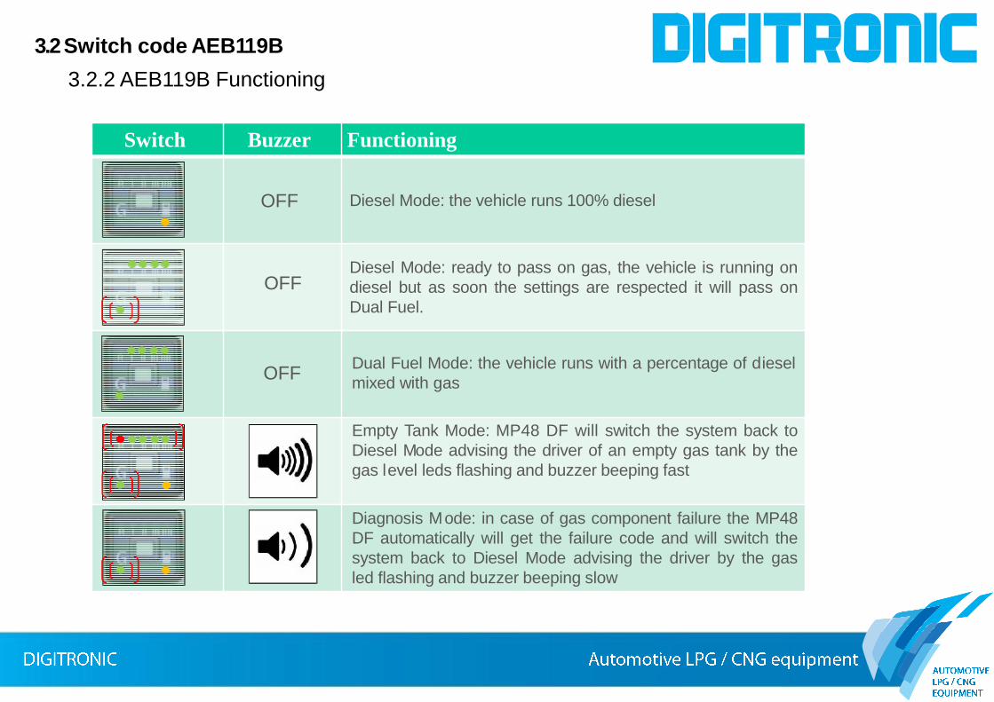
Switch Buzzer Functioning
Diesel Mode: the vehicle runs 100% diesel
Diesel Mode: ready to pass on gas, the vehicle is running on
diesel but as soon the settings are respected it will pass on
Dual Fuel.
OFF
OFF
OFF
Empty Tank Mode: MP48 DF will switch the system back to
Diesel Mode advising the driver of an empty gas tank by the
gas level leds flashing and buzzer beeping fast
Diagnosis Mode: in case of gas component failure the MP48
DF automatically will get the failure code and will switch the
system back to Diesel Mode advising the driver by the gas
led flashing and buzzer beeping slow
Dual Fuel Mode: the vehicle runs with a percentage of diesel
mixed with gas
3.2 Switch code AEB119B
3.2.2 AEB119B Functioning

Technical specification
Supply voltage range Vbatt=10÷16V
Operating temperature range -40÷120°C
Current Absorbing with actuators
disable
Imax < 0,5°
Current Absorbing in Standby mode Istandby < 5mA
Gas Injectors Managed Up to 2 injectors; Imax=6° Vbat max=16V
Gas Valve output Pmax=25W, Imax=2A (power & current when both the output are used)
Pmax=50W, Imax=4A (power & current when only one output is used)
Analogue sensors managed Gas pressure & temperature sensor
MAP Sensor
Water temperature sensor
Exhaust Temperature sensor
Linear Oxygen sensor (Bosch & NTK)
Gas Level Gauge (AEB, 0-90ohm, Not standard and Not standard
inverted)
RPM sensor Hal Effect and Inductive type
Switch AEB119B
3.3 Dual Fuel ECU code MP48 DF
3.3.1 Digitronic MP48 DF Characteristics
3.3 Dual Fuel ECU code MP48 DF
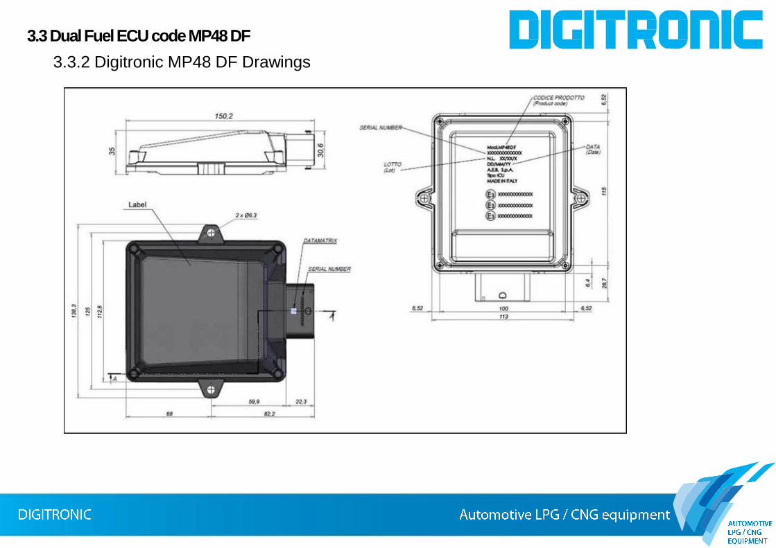
3.3.2 Digitronic MP48 DF Drawings
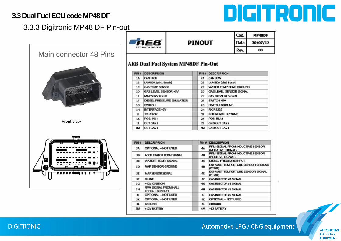
Main connector 48 Pins
3.3 Dual Fuel ECU code MP48 DF
3.3.3 Digitronic MP48 DF Pin-out
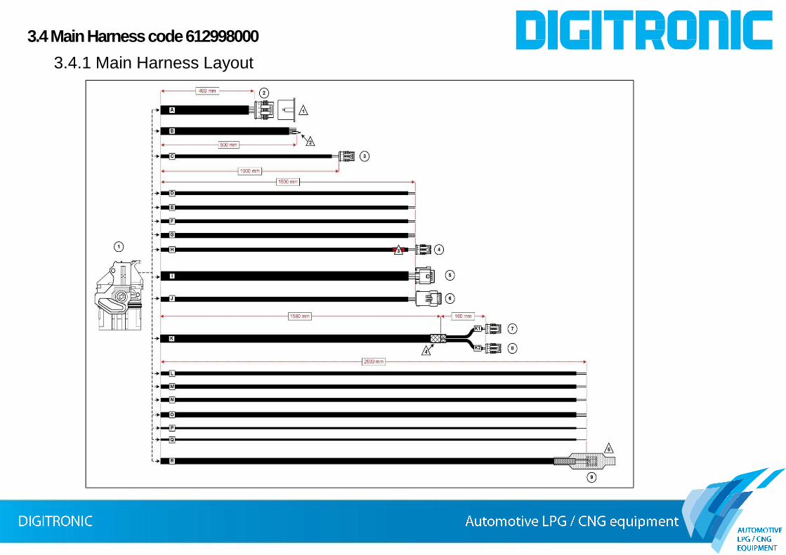
3.4 Main Harness code 612998000
3.4.1 Main Harness Layout

3.4 Main Harness code 612998000
3.4.2 Main Harness Diagram

3.4 Main Harness code 612998000
3.4.3 Main Harness Component Description
Nr. Description In/out
1 MP48DF Main connector; CMC Molex Type 48 ways, female contacts In-out
2 Data link connector; AMP Superseal type, 4 ways female contacts with CAP In-Out
3 Exhaust Gas Temperature connector; AMP Superseal type , 2 ways female contacts In
4 Reducer Gas valve connector; AMP Superseal type , 2 ways female contacts Out
5 Gas Pressure & Temperature sensor Connector; MQS Tyco type, 4 ways female contacts In
6 MAP sensor connector; Sicma FCI type, 4 ways felame contacts In
7 Gas Injector 1 connector; AMP Superseal type , 2 ways female contacts Out
8 Gas Injector 2 connector; AMP Superseal type , 2 ways female contacts Out
9 Mode Selection Switch, PAP-04V-S PA JST sries, 4 ways female contacts In-out
B Sheath 5 wires Level Sender Green = Level supply (5V) White = Level signal Black 0,5mm2 = ground
Out In
Out
Second gas Valve Blue-White = activation signal Black Ø1,5mm2 = ground
Out Out
D Sheath 2 wires Oxygen sensor Gray = Signal (pin 1) Violet = Signal (pin 5)
In In
E Sheath 2 wires Water Temperature
Orange = signal Black = ground
In Out
F Sheath 2 wires 12V Battery Supply
Red-Black = power supply (12V) Black= Ground
In In
G Sheath 3 wires RPM signal Yellow-Black = inductive positive signal Yellow= inductive negative signalBlue = Holl effect signal
InInIn
L Sheath 2 wires Diesel Pressure Sensor
Red = Sensor signal (Sensor Side)Red-black = Sensor Emulation (ECU side)
In Out
M Sheath 2 wires NOT USED Green / Greeen-Black
N Sheath 2 wires Accelerator Pedal Blue = NOT USEDBlue-Yellow = Signal
------In
O Sheath 3 wires CAN Bus Yellow-Green = CAN H to pin 6 OBD plug Yellow-Gray = CAN L to pin 14 OBD plug Green = K Lineto pin 7 OBD plug
InInIn
P Sheath 1 wire 12V Ignition Red-White = 12V ignition In
Q Sheath 1 wire NOT USED Blue-Red -----
a
c
bb
cd
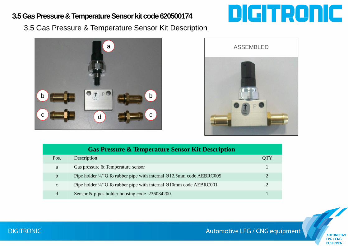
Gas Pressure & Temperature Sensor Kit Description
ASSEMBLED
Pos. Description QTY
a Gas pressure & Temperature sensor 1
b Pipe holder ¼’’G fo rubber pipe with internal Ø12,5mm code AEBRC005 2
c Pipe holder ¼’’G fo rubber pipe with internal Ø10mm code AEBRC001 2
d Sensor & pipes holder housing code 236034200 1
3.5 Gas Pressure & Temperature Sensor kit code 620500174
3.5 Gas Pressure & Temperature Sensor Kit Description

3.5 Gas Pressure & Temperature Sensor kit code 620500174
3.5.1 Gas Pressure & Temperature Drawing

3.5 Gas Pressure & Temperature Sensor kit code 620500174
3.5.2 Gas Pressure & Temperature Characteristics

Aluminum 2011 95HB
3.5 Gas Pressure & Temperature Sensor kit code 620500174
3.5.3 Sensor & Pipes Housing

Pipe Older
Pos. Description
1 O-Ring O-Ring 10x1.5 Viton 75Sh
2 Pipe holder Brass Available 1/4"G pipe Ø12,5
Pipe Older
Pos. Description
1 O-Ring O-Ring 10x1.5 Viton 75Sh
2 Pipe holder Brass Available 1/4"G pipe Ø10,5
3.5 Gas Pressure & Temperature Sensor kit code 620500174
3.5.4 Rubber Pipes holder
Gas Pressure & Temperature Sensor Kit Description
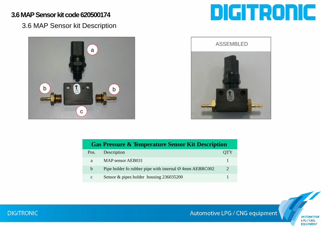
ASSEMBLEDa
bb
c
Pos. Description QTY
a MAP sensor AEB031 1
b Pipe holder fo rubber pipe with internal Ø 4mm AEBRC002 2
c Sensor & pipes holder housing 236035200 1
3.6MAP Sensorkit code 620500174
3.6 MAP Sensor kit Description

Pin-out
Pin Description
1 Groud
2 Power Supply +5V
3 MAP Signal
4 Not used
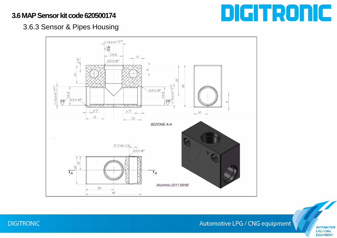
3.6MAP Sensorkit code 620500174
3.6.1 MAP Sensor Drawing

3.6MAP Sensorkit code 620500174
3.6.2 MAP Sensor Characteristics
3.6MAP Sensorkit code 620500174
3.6.3 Sensor & Pipes Housing

Pipe Older
Pos. Description
1 O-Ring O-Ring 10x1.5 Viton 75Sh
2 Pipe holder Brass Available 1/4"G pipe Ø4
3.6MAP Sensorkit code 620500174
3.6.4 Rubber Pipes holder

a
b
c
Exhaust Gases d
Gas Pressure & Temperature Sensor Kit Description
Weld
ASSEMBLED
Pos. Description QTY
a Exhaust Temperature probe 1
b Temperature Sensor Adapter 236003070 1
c Copper Washer 1
d Oxygen sensor Housing 121003010 1
3.7Exhaust Temperature Sensor kitcode 620500172
3.7 Exhaust Temperature Kit Description

4. Components Connections
Switch
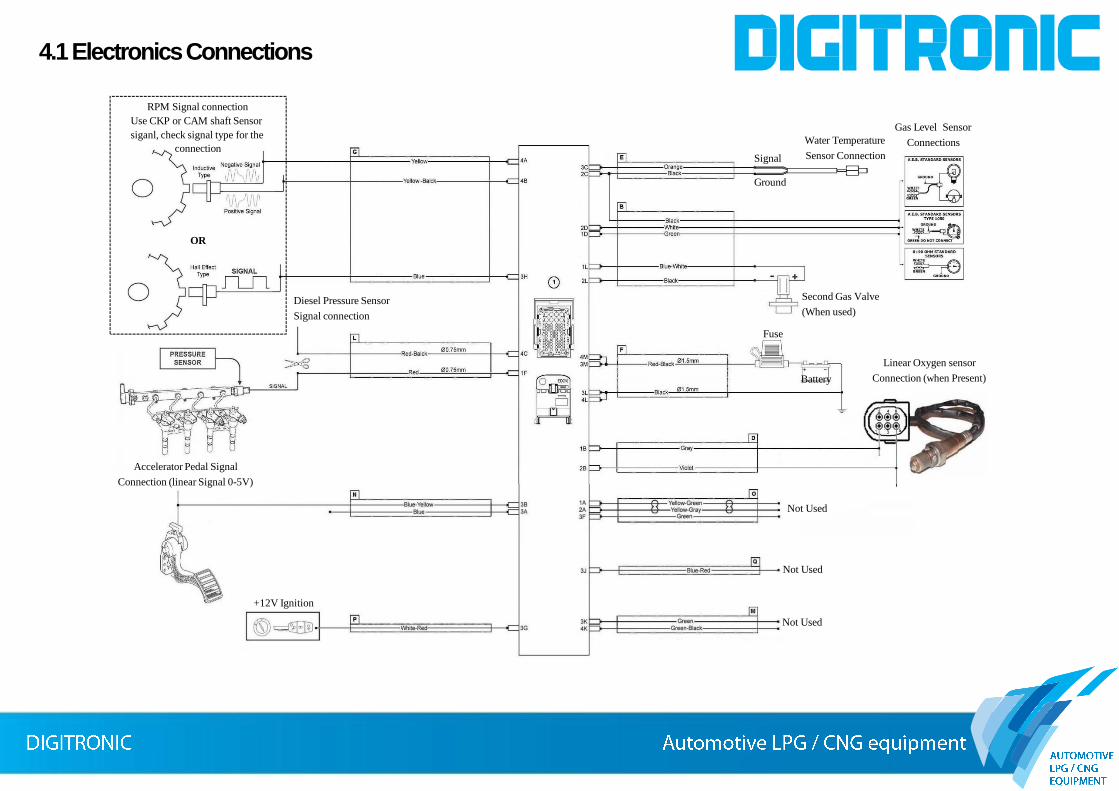
Second Gas Valve
(When used)
Fuse
Gas Level Sensor
Connections
Linear Oxygen sensor
Connection (when Present)Battery
Water Temperature
Sensor ConnectionSignal
Not Used
Not Used
Not Used
Accelerator Pedal Signal
Connection (linear Signal 0-5V)
Diesel Pressure Sensor
Signal connection
RPM Signal connection
Use CKP or CAM shaft Sensor
siganl, check signal type for the
connection
OR
+12V Ignition
4.1 Electronics Connections
Ground