Mounted or Pull Type
32
Great Plains, 90’ Mounted or Pull Type
Transcript of Mounted or Pull Type
Great Plains, 90’Mounted or Pull Type


Manual # 016-0230-068 REV A 09/06
1
C H A P T E R
INTRODUCTION
Congratulations on your purchase of the Raven Autoboom system! This system is designedto provide worry-free operation of your hydraulically controlled booms. The following in-structions are designed to assist you in the proper installation of the system hardware. TheAutoboom hydraulic installation process is fairly straight forward and prior knowledge ofthe machine’s hydraulic system is beneficial. Be sure to carefully follow the safety andinstallation instructions of this manual. Be sure to pay careful attention to the hydraulicsinstallation. Improper installation could result in a system that does not work correctly.Following the completion of the hardware installation, refer to the instructions in the PowerGlide, Power Glide Plus and Ultra Glide Calibration and Operator’s manual.
This manual gives the installation instructions for the Power Glide, Power Glide Plus, andUltra Glide Systems. Be sure to identify which system you have and follow only the instruc-tions for that system.

Great Plains 90’, Mounted or Pull Type Autoboom Installation Manual
2
Basic KitContents
PowerGlide System
w Hardware Installation Kit 117-0230-068w Hydraulic Hose and Fitting Kitw Hydraulic Valve and Mounting Hardwarew Axle Mounting Brackets and Mounting
w Axle Kit 117-0131-w 2 Axles
w Controller Kit 117-0137-022w In-Cab Controllerw Main Harness Cablew Power Cable (Controller to Switched Power Source)
PowerGlide Plus System
w Hardware Installation Kit 117-0231-068w Wheel Kitw Hydraulic Hose and Fitting Kit.w Hydraulic Valve and Mounting Hardware
w Controller Kit 117-0137-023w Main Harness Cablew Power Cable (Controller to Switched Power Source)w CAN Node
UltraGlide System
w Hardware Installation Kit 117-0232-068w Ultrasonic Sensorsw Hydraulic Hose and Fitting Kit.w Hydraulic Valve and Mounting Hardware
w Controller Kit 117-0137-024w Main Cablew Power Cable (Controller to Switched Power Source)w CAN Node
Installation Manual Machine Reference
Make: Great Plains Model: 90’ Boom Year: 2006
Serial Number:

Manual # 016-0230-068 REV A 09/06
3
C H A P T E R
SAFETY
This section is divided between general safety precautions, specific safety mea-sures in respect to the hydraulic and electrical system, and machine driving andoperating safety.
Important: The machine must remain stationary and switchedoff, the booms unfolded and supported, while installation ormaintenance is conducted.
Safety Precautions
When working with or near a machine with Autoboom installed, the followingsafety measures must be observed. The operator must:
w Be alert and aware of surroundings.w Not operate Autoboom or any agricultural equipment while under the
influence alcohol or an illegal substance.w Remain in the operator’s position in the machine at all times when Autoboom
is engaged.w Disable Autoboom when exiting from the operator’s seat and machine.w Not drive the machine with Autoboom enabled on any public thorough-
fare or main road.w Determine and remain a safe working distance from other individuals.
The operator is responsible for disabling Autoboom when the safe work-ing distance has diminished.
w Ensure Autoboom is disabled prior to starting any maintenance work onAutoboom or machine.
InstallationSafetyRequirements
Great Plains 90’, Mounted or Pull Type Autoboom Installation Manual
4
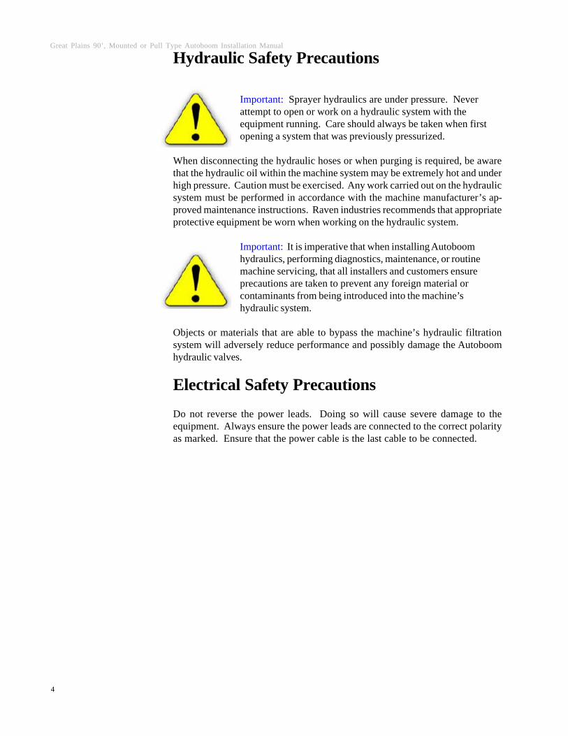
Hydraulic Safety Precautions
Important: Sprayer hydraulics are under pressure. Neverattempt to open or work on a hydraulic system with theequipment running. Care should always be taken when firstopening a system that was previously pressurized.
When disconnecting the hydraulic hoses or when purging is required, be awarethat the hydraulic oil within the machine system may be extremely hot and underhigh pressure. Caution must be exercised. Any work carried out on the hydraulicsystem must be performed in accordance with the machine manufacturer’s ap-proved maintenance instructions. Raven industries recommends that appropriateprotective equipment be worn when working on the hydraulic system.
Important: It is imperative that when installing Autoboomhydraulics, performing diagnostics, maintenance, or routinemachine servicing, that all installers and customers ensureprecautions are taken to prevent any foreign material orcontaminants from being introduced into the machine’shydraulic system.
Objects or materials that are able to bypass the machine’s hydraulic filtrationsystem will adversely reduce performance and possibly damage the Autoboomhydraulic valves.
Electrical Safety Precautions
Do not reverse the power leads. Doing so will cause severe damage to theequipment. Always ensure the power leads are connected to the correct polarityas marked. Ensure that the power cable is the last cable to be connected.

Manual # 016-0230-068 REV A 09/06
5
This section outlines the safety requirements used when driving a vehicle usingthe Autoboom system.
Areas of Operation
The Autoboom must only be used on private property without public access. Itmust only be used within cleared fields. It must not be used when traveling on anypublic roads or access ways. Raven Industries advises that users familiarizethemselves with Autoboom operation by first reading the Autoboom InstallationManual and the PowerGlide, PowerGlide Plus, or UltraGlide Calibration andOperator’s Manual.
Avoidance of People
Autoboom must not be operated in the vicinity of people. Bystanders must bewell outside of the machine’s path while Autoboom is enabled.
Avoidance of Machinery and Equipment
The Autoboom operator must allow a safe distance between the machine’s pathand other machinery or equipment. To determine a safe distance, take into ac-count the incorrect operation of the boom management system and the width ofthe booms.
Avoidance of Obstacles
Autoboom CANNOT detect obstacles such as fences, trees, or boulders that arenot located within the sensor or wheel path. The machine operator must identifyand avoid obstacles that are not able to be detected by the boom sensors or wheelswhile working in a field.
Responsibilities of Operator
The operator must remain in complete control of the machine at all times. Onlywhen Autoboom is enabled can there be hands-free operation of the booms. Theoperator remains fully responsible for the operation of the machine and must re-main in the operator’s seat at all times while Autoboom is enabled.
Disengaging Boom Control
The operator must naturally lift the booms if an obstacle is in the line of travel andis not detected by the sensor or wheels. Pressing the “Up” function on the boomcontroller will disengage Autoboom if Boom Sense wires have been installed.
Driving SafetyRequirements
Great Plains 90’, Mounted or Pull Type Autoboom Installation Manual
6
We welcome your feedback about this manual. If you have any comments orsuggestions for improvement, please let us know by contacting our CustomerSupport Center by any of the following methods:
w Via phone: 1-800-243-5435
w Via mail:Raven IndustriesFlow Control Division205 E. 6th St.Sioux Falls, SD 57104
w Via email: [email protected]
ContactingRavenIndustries

Manual # 016-0230-068 REV A 09/06
7
C H A P T E R
POPULATING AND MOUNTING THE VALVE
Mount valve block to right of machine stack valve
POWER GLIDE
FITTING PORT9/16" JIC (M) to 9/16" SAE O-Ring (M) LC, RC3/4" JIC (M) to 3/4" SAE O-Ring (M) P (Filter), T
9/16" JIC (M/F) 90° Elbow LC, RC**9/16" JIC (M) to 9/16" SAE O-Ring (M) LV, RV
**NOTE: Remove orificed fittings from left and right tilt cylinders and install into LV, RV ports.

Great Plains 90’, Mounted or Pull Type Autoboom Installation Manual
8
Power GlideDualCartridgeOption
1. Remove cavity plug (5A) and port plug (6A).
2. Discard port plug (6A) or keep for future upgrade to Power Glide Plus.
3. Insert cavity plug from port 5A into port 6A.
4. Install mechanical cartridge into port 5A.

Manual # 016-0230-068 REV A 09/06
9
C H A P T E R
HYDRAULIC HOSE & FITTINGS INSTALLATION
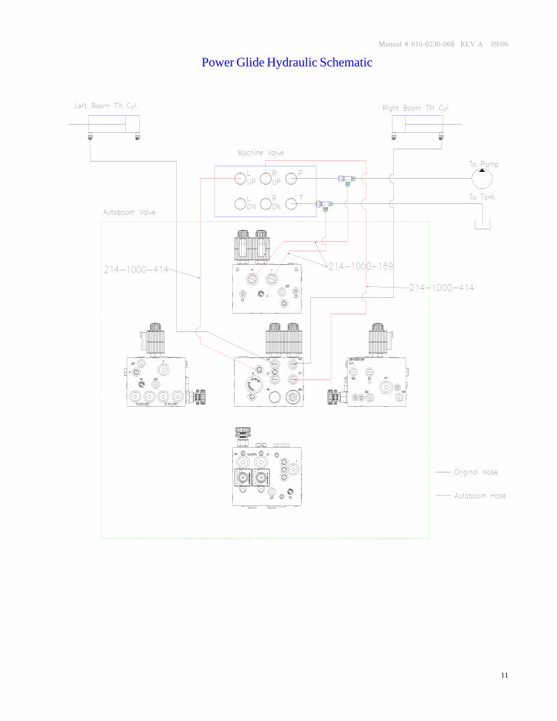
Pressure and Tank Lines
Pressure and tank tee in
ORIENTATION
P/N HOSE END LOCATION HOSE END LOCATION214-1000-169 3/4" JIC (F) Pressure Line Tee 3/4" JIC (F) P (Filter)214-1000-169 3/4" JIC (F) Tank Line Tee 3/4" JIC (F) T214-1000-414 9/16" JIC (F) Left Tilt Up 9/16" JIC (F) 90° LV214-1000-414 9/16" JIC (F) Right Tilt Up 9/16" JIC (F) 90° RV
MACHINE AUTOBOOM VALVE

Great Plains 90’, Mounted or Pull Type Autoboom Installation Manual
10
LC, RC, LV, RV
- Remove orificed fittings from tilt cylinders and install into LV and RVports.
- Install supplied non-orificed fittings on tilt cylinders.
Manual # 016-0230-068 REV A 09/06
11
Power Glide Hydraulic Schematic
Great Plains 90’, Mounted or Pull Type Autoboom Installation Manual
12
C H A P T E R
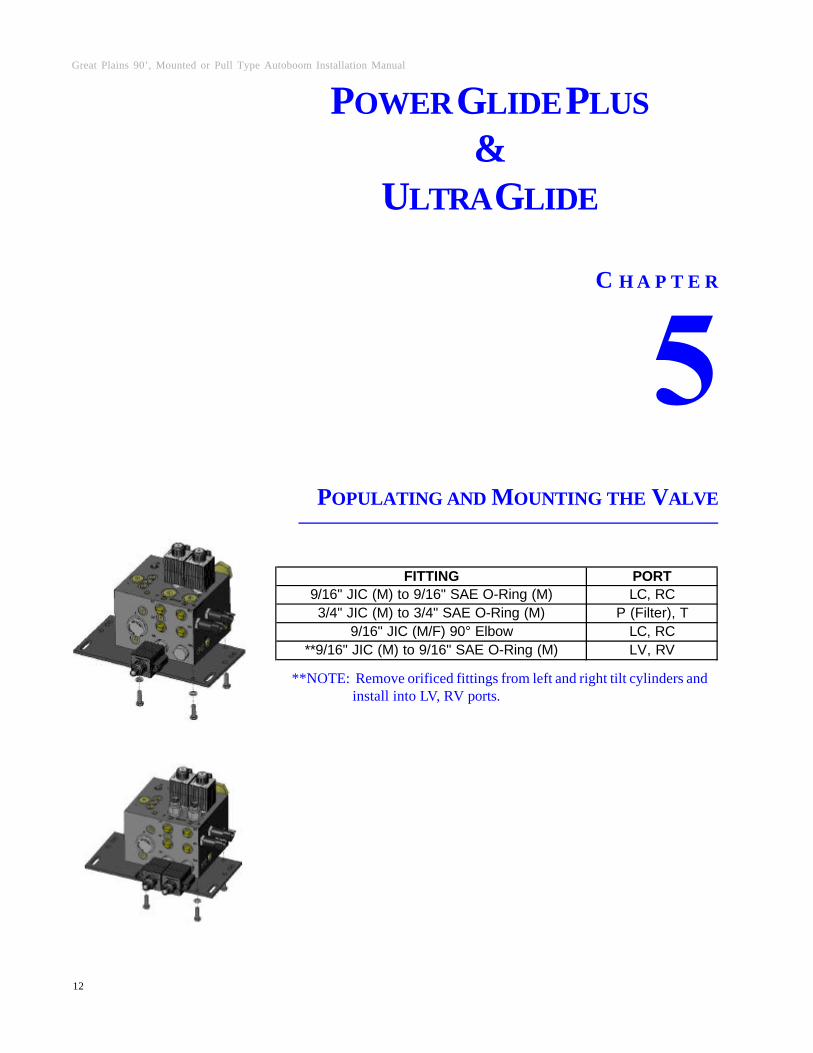
POPULATING AND MOUNTING THE VALVE
POWER GLIDE PLUS&
ULTRA GLIDE
FITTING PORT9/16" JIC (M) to 9/16" SAE O-Ring (M) LC, RC3/4" JIC (M) to 3/4" SAE O-Ring (M) P (Filter), T
9/16" JIC (M/F) 90° Elbow LC, RC**9/16" JIC (M) to 9/16" SAE O-Ring (M) LV, RV
**NOTE: Remove orificed fittings from left and right tilt cylinders and install into LV, RV ports.

Manual # 016-0230-068 REV A 09/06
13
NOTE: Ultra Glide - Make sure floating orifice in LC and RC ports are installedwith slot facing out.
Mount valve block to right of machine stack valve
Great Plains 90’, Mounted or Pull Type Autoboom Installation Manual
14
C H A P T E R
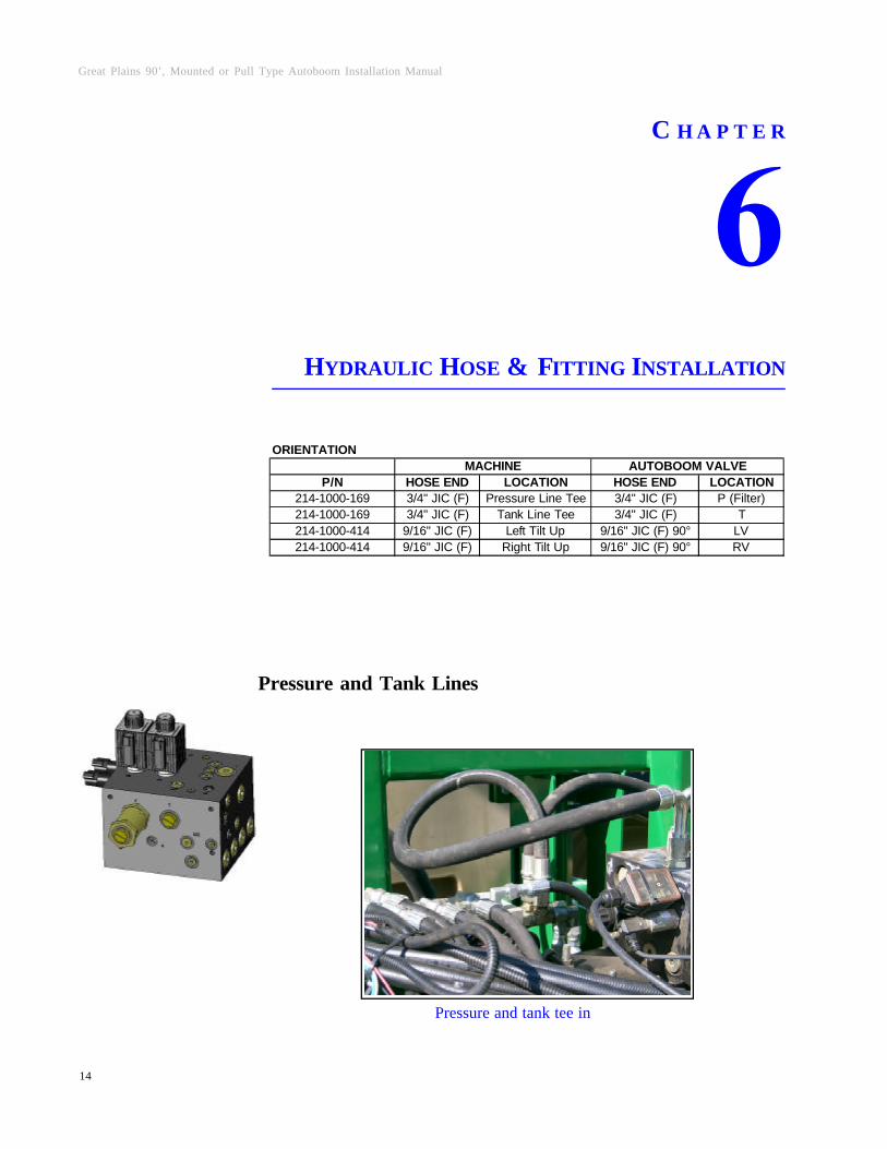
HYDRAULIC HOSE & FITTING INSTALLATION
Pressure and Tank Lines
Pressure and tank tee in
ORIENTATION
P/N HOSE END LOCATION HOSE END LOCATION214-1000-169 3/4" JIC (F) Pressure Line Tee 3/4" JIC (F) P (Filter)214-1000-169 3/4" JIC (F) Tank Line Tee 3/4" JIC (F) T214-1000-414 9/16" JIC (F) Left Tilt Up 9/16" JIC (F) 90° LV214-1000-414 9/16" JIC (F) Right Tilt Up 9/16" JIC (F) 90° RV
MACHINE AUTOBOOM VALVE

Manual # 016-0230-068 REV A 09/06
15
LC, RC, LV, RV
w Remove orificed fittings from tilt cylinders and install into LV and RV ports.
w Install supplied non-orificed fittings into tilt cylinders.
Great Plains 90’, Mounted or Pull Type Autoboom Installation Manual
16
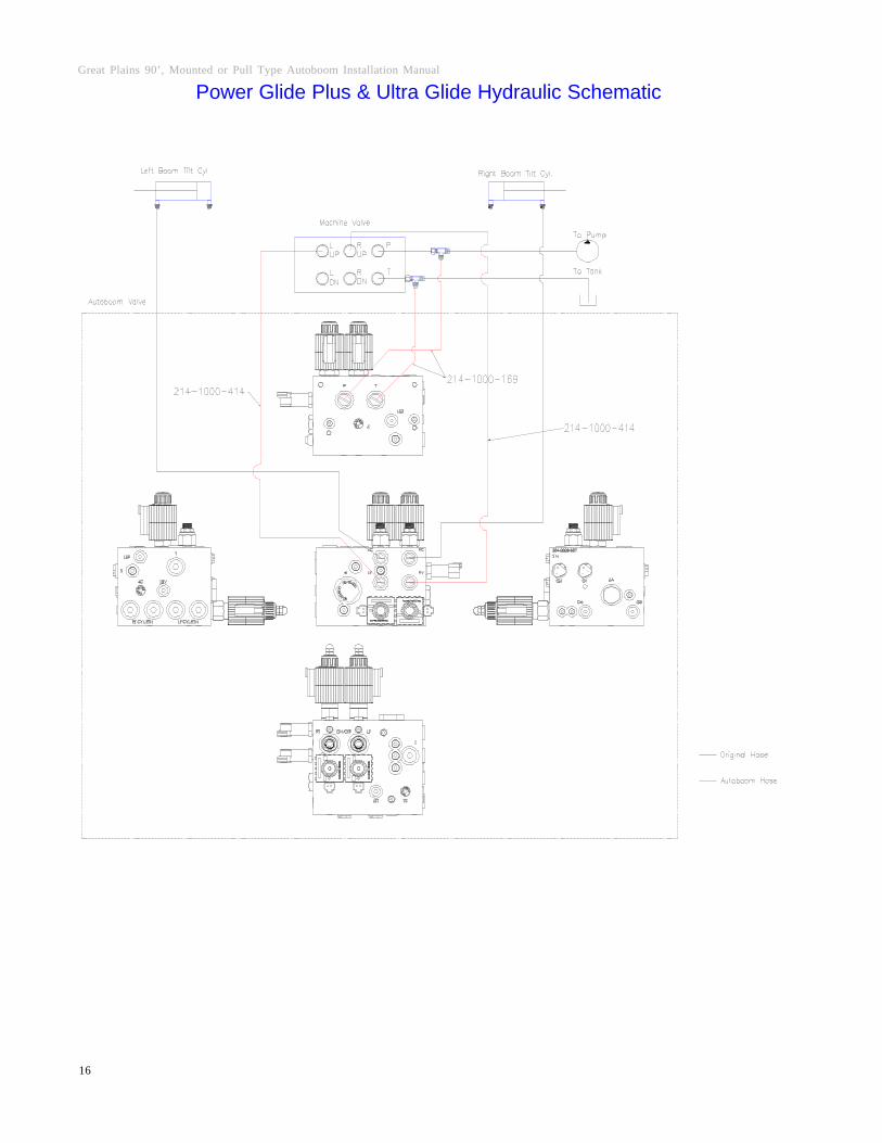
Power Glide Plus & Ultra Glide Hydraulic Schematic

Manual # 016-0230-068 REV A 09/06
17
C H A P T E R
WHEEL & SENSOR MOUNTING
WheelMounting
Mount axle bracket just inside boom fold

Great Plains 90’, Mounted or Pull Type Autoboom Installation Manual
18
SensorMounting
Mount sensor near boom tip
Manual # 016-0230-068 REV A 09/06
19
C H A P T E R
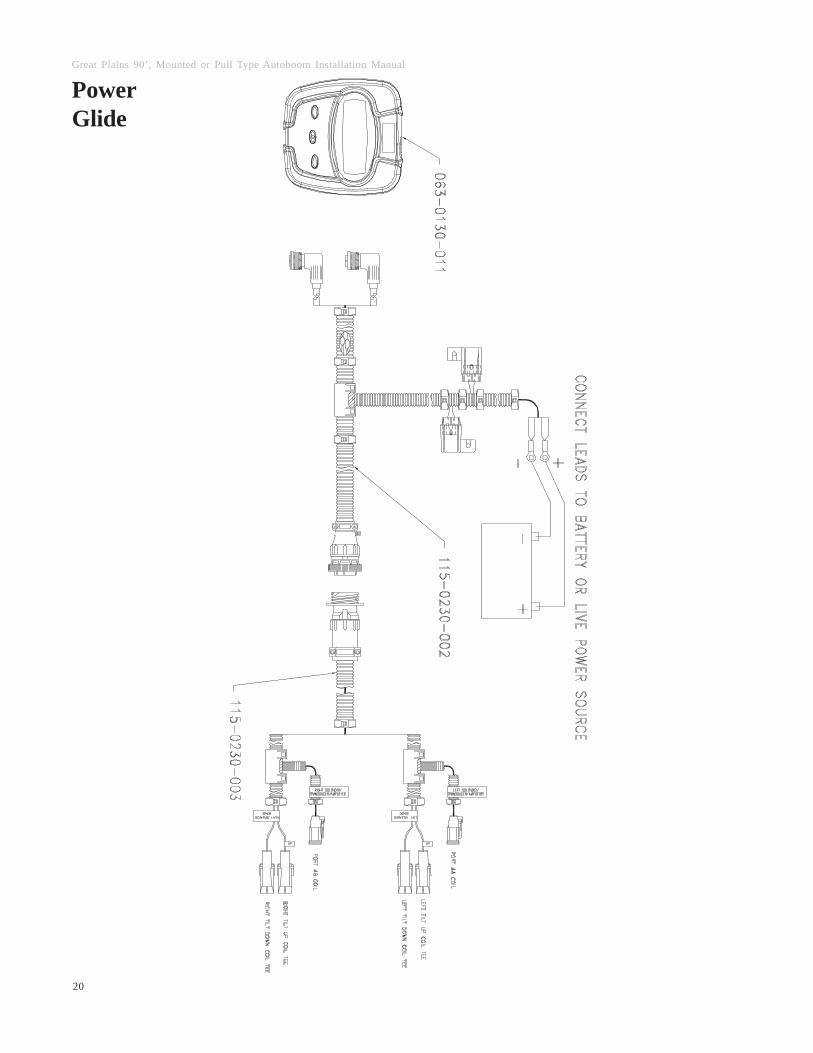
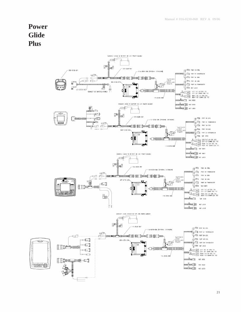
CONTROLLER & WIRING HARNESS
w Use the following diagrams to install the wiring harness.
w Be sure to allow enough slack in harness when racking booms.
w Connect power leads to battery.
Great Plains 90’, Mounted or Pull Type Autoboom Installation Manual
20
PowerGlide
Manual # 016-0230-068 REV A 09/06
21
PowerGlidePlus

Great Plains 90’, Mounted or Pull Type Autoboom Installation Manual
22
UltraGlide

Manual # 016-0230-068 REV A 09/06
23
A P P E N D I X
REPLACEMENT PARTS
On the following pages you will find replacement part diagrams and listingsfor Power Glide, Power Glide Plus, and Ultra Guide systems. Please referto these diagrams when calling to request replacement parts.
Great Plains 90’, Mounted or Pull Type Autoboom Installation Manual
24
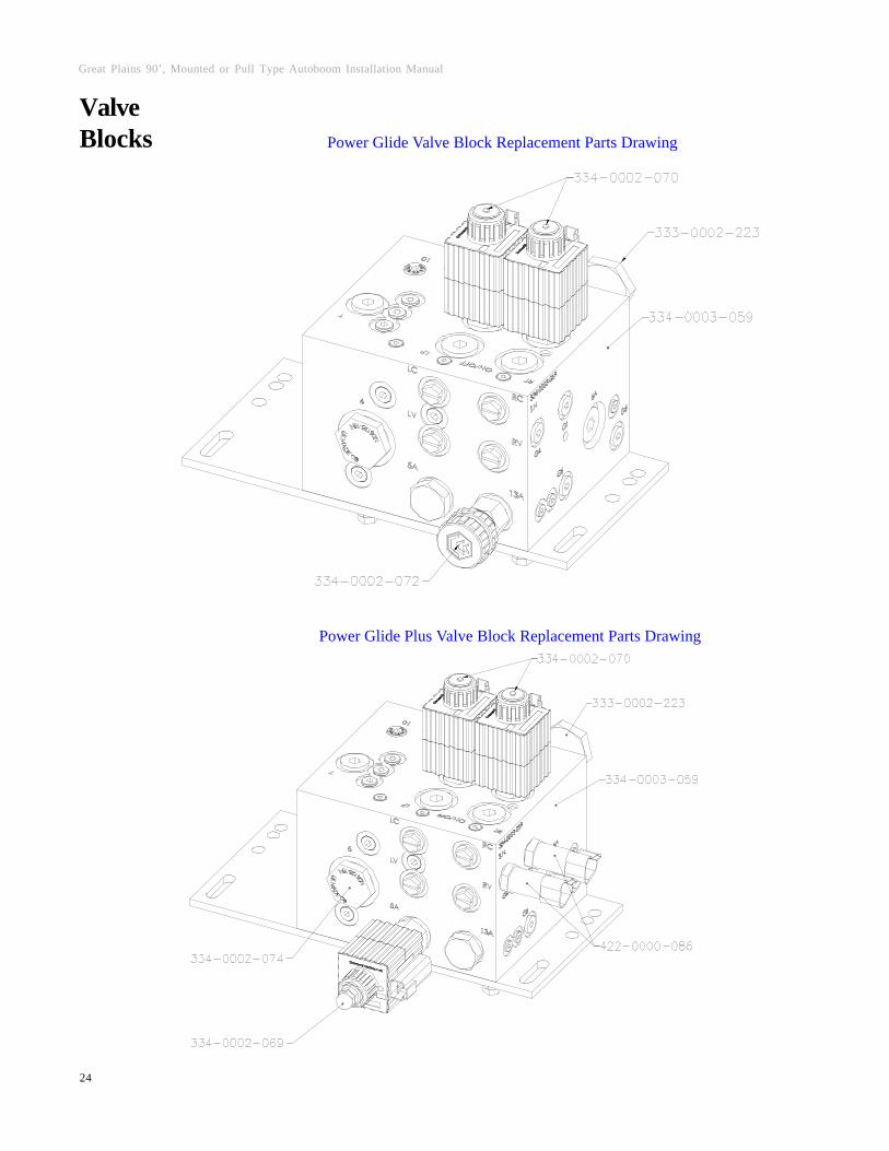
ValveBlocks Power Glide Valve Block Replacement Parts Drawing
Power Glide Plus Valve Block Replacement Parts Drawing
Manual # 016-0230-068 REV A 09/06
25
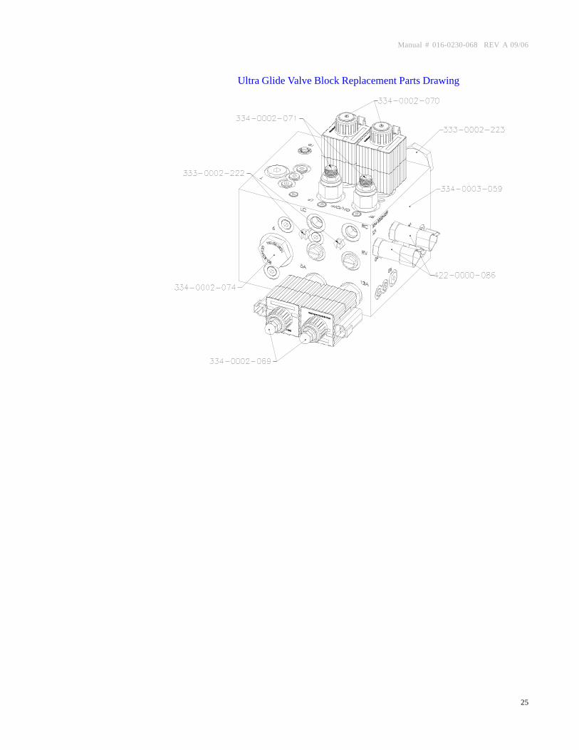
Ultra Glide Valve Block Replacement Parts Drawing
Great Plains 90’, Mounted or Pull Type Autoboom Installation Manual
26
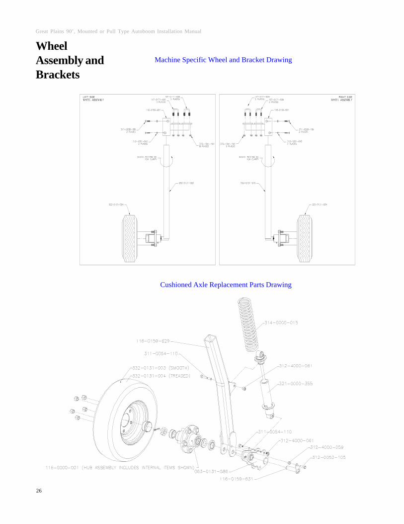
WheelAssembly andBrackets
Machine Specific Wheel and Bracket Drawing
Cushioned Axle Replacement Parts Drawing

Manual # 016-0230-068 REV A 09/06
27
Sensor andBrackets Machine Specific Sensor Bracket Drawing
New Molded Sensor Replacement Parts Drawing

Great Plains 90’, Mounted or Pull Type Autoboom Installation Manual
28
NOTES:

RAVEN INDUSTRIES
LIMITED WARRANTY
WHAT IS COVERED?
This warranty covers all defects in workmanship or materials in your RavenFlow Control Product under normal use, maintenance, and service.
HOW LONG IS THE COVERAGE PERIOD?
This warranty coverage runs for 12 months from the purchase date of yourRaven Flow Control Product. This warranty coverage applies only to theoriginal owner and is not transferrable.
HOW CAN YOU GET SERVICE?
Bring the defective part, and proof of date of purchase, to your local dealer. Ifyour dealer agrees with the warranty claim, he will send the part, and proofof purchase to his distributor or to Raven for final approval.
WHAT WILL RAVEN INDUSTRIES DO?
When our inspection proves the warranty claim, we will, at our option, repairor replace the defective part and pay for return freight.
WHAT DOES THIS WARRANTY NOT COVER?
Raven Industries will not assume any expense or liability for repairs madeoutside our plant without written consent. We are not responsible for damageto any associated equipment or product and will not be liable for loss of profitor other special damages. The obligation of this warranty is in lieu of allother warranties, expressed or implied, and no person is authorized toassume for us any liability. Damages caused by normal wear and tear, mis-use, abuse, neglect, accident, or improper installation and maintenance arenot covered by this warranty.

Great P
lains 90’, Mounted or P
ull Type Autoboom
Installation Manual (P
/N 016-0230-068 R
ev A 9/06)
Notice: This document and the information provided are the property of Raven Industries, Inc. andmay only be used as authorized by Raven Industries, Inc. All rights reserved under the copyright laws.
Raven IndustriesFlow Controls DivisionP.O. Box 5107Sioux Falls, SD 57117-5107
Toll Free 800-243-5435Fax 605-331-0426