Motor SCM 012-130 ISO - KRAMP · PDF file012 017 025 034 040 047 056 064 084 090 108 130 ......
12
1 (12) 012 017 025 034 040 047 056 064 084 090 108 130 12.6 17.0 25.4 34.2 41,2 47.1 56.7 63.5 83.6 90.7 108.0 130.0 40 40 40 40 40 40 40 40 40 40 40 35 35 35 35 35 35 35 35 35 35 35 35 30 8800 8800 7000 7000 6300 6300 6300 6300 5200 5200 5200 5200 8000 8000 6300 6300 5700 5700 5700 5700 4700 4700 4700 4700 300 300 300 300 300 300 300 300 300 300 300 300 54 74 86 115 125 145 175 195 215 230 275 285 20 25 40 55 60 65 80 90 100 110 130 135 2.0 2.7 4.0 5.4 6.6 7.5 8.9 10.0 13.3 14.4 17.1 20.5 0.9 0.9 1.1 1.1 2.6 2.6 2.6 2.6 7.4 7.4 7.4 7.4 8.5 8.5 9.5 9.5 16.5 16.5 16.5 16.5 28.0 28.0 30.5 30.5 Displacement cm 3 ⁄rev. Working pressure max. intermittent MPa max. continuous MPa Revolutions max. intermittent rpm max. continuous rpm min. continuous rpm Power max. intermittent kW max. continuous kW Start torque theoretical value Nm⁄MPa Mass moment of inertia ( x 10 -3 ) kg m 2 Weight kg Type SUNFAB SCM is a range of robust axial piston motors especially suitable for mobile hydraulics. SUNFAB SCM is of the bent-axis type with spherical pistons. The design results in a compact motor with few moving parts, high starting torque and high reliability. Motor SCM 012-130 ISO 3201 GB The SCM covers the entire displacement range 12-130 cm 3 /rev at a maximum working pressure of 40 MPa. SUNFAB SCM’s well dimensioned, double tapered roller bearings permit high shaft loads and lead to excellent speed characteristics. SUNFAB SCM’s high level of reliability is based on the choice of materials, hardening methods, surface structures and the quality assured manufacturing process. Data concerning RPM are based on maximum premitted peripheral velocity of the tapered roller bearing. Max intermittent power data may vary dependent on application. For further information please contact Sunfab. Continuous power data are based on maximum output power without external cooling of the motor housing. Intermittent duty is defined as follows: max 6 seconds per minute, e g peak RPM when unloading or accelerating.
Transcript of Motor SCM 012-130 ISO - KRAMP · PDF file012 017 025 034 040 047 056 064 084 090 108 130 ......

1 (12)
012 017 025 034 040 047 056 064 084 090 108 130 12.6 17.0 25.4 34.2 41,2 47.1 56.7 63.5 83.6 90.7 108.0 130.0
40 40 40 40 40 40 40 40 40 40 40 35 35 35 35 35 35 35 35 35 35 35 35 30
8800 8800 7000 7000 6300 6300 6300 6300 5200 5200 5200 5200 8000 8000 6300 6300 5700 5700 5700 5700 4700 4700 4700 4700 300 300 300 300 300 300 300 300 300 300 300 300
54 74 86 115 125 145 175 195 215 230 275 285 20 25 40 55 60 65 80 90 100 110 130 135
2.0 2.7 4.0 5.4 6.6 7.5 8.9 10.0 13.3 14.4 17.1 20.5
0.9 0.9 1.1 1.1 2.6 2.6 2.6 2.6 7.4 7.4 7.4 7.4
8.5 8.5 9.5 9.5 16.5 16.5 16.5 16.5 28.0 28.0 30.5 30.5
Displacement cm3⁄rev. Working pressure max. intermittent MPamax. continuous MPaRevolutions max. intermittent rpmmax. continuous rpmmin. continuous rpmPowermax. intermittent kWmax. continuous kWStart torque theoretical value Nm⁄MPa Mass moment of inertia ( x 10 -3) kg m2
Weight kg
Type
SUNFAB SCM is a range of robust axial piston motors especially suitable for mobile hydraulics.
SUNFAB SCM is of the bent-axis type with spherical pistons. The design results in a compact motor with few moving parts, high starting torque and high reliability.
Motor SCM 012-130 ISO3201 GB
The SCM covers the entire displacement range 12-130 cm3/rev at a maximum working pressure of 40 MPa.
SUNFAB SCM’s well dimensioned, double taperedroller bearings permit high shaft loads and lead to excellent speed characteristics.
SUNFAB SCM’s high level of reliability is based on the choice of materials, hardening methods, surface structures and the quality assured manufacturing process.
Data concerning RPM are based on maximum premitted peripheral velocity of the tapered roller bearing.Max intermittent power data may vary dependent on application. For further information please contact Sunfab.
Continuous power data are based on maximum output power without external cooling of the motor housing.Intermittent duty is defi ned as follows: max 6 seconds per minute, e g peak RPM when unloading or accelerating.

2 (12)
012 017 025 034 040 047 056 064 084 090 108 130
S1 - - - - - - - - X X X X
S2 - - - - X X X X - - - -
S3 X X X X - - - - - - - -
V1 - - - - - - - - X X X X
V2 - - X X X X X X X X X X
R1 - - X X X X X X X X X X
K3 X X X X - - - - - - - -
*
012 017 025 034 040 047 056 064 084 090 108 130
G ISO G* X X X X - - - - - - - -
M - - X X X X X X X X X X
U UN*** X X X X X X X X X X X X
*
**
***
1
012 017 025 034 040 047 056 064 084 090 108 130
00 X X X X X X X X X X X X
P1 X X X X X X X X - - - -
S1 X X X X X X X X - - - -
S2 X X X X X X X X - - - -
*
SC
M
012 017 025 034 040 047 056 064 084 090 108 130
W
N
H
V
ISO 3019-2 012 017 025 034 040 047 056 064 084 090 108 130
I41 X X - - - - - - - - - -
I42 O O X X - - - - - - - -
I43 - - - - X X X X - - - -
I44 - - - - - - - - X X (X) (X)
I45 - - - - - - - - (X) (X) X X
012 017 025 034 040 047 056 064 084 090 108 130
W20 W20x1.25x14x9g X X - - - - - - - - - -
W25 W25x1.25x18x9g X X X (X) - - - - - - - -
W30 W30x2x14x9g - - X X X X X O - - - -
W32 W32x2x14x9g - - - - X X X O - - - -
W35 W35x2x16x9g - - - - X X X X X X - -
W40 W40x2x18x9g - - - - - - - - X X X O
W45 W45x2x21x9g - - - - - - - - X X X X
K20 ø 20 k6 X X - - - - - - - - - -
K25 ø 25 k6 X X X (X) - - - - - - - -
K30 ø 30 k6 O O X X X X X O - - - -
K35 ø 35 k6 - - - - X X X X - - - -
K40 ø 40 k6 - - - - - - - - X X (X) -
K45 ø 45 k6 - - - - - - - - X X X X
SC M - 012 W - N - I41 - W25 - S3 G - 1 00
1 2 3 - 4 - 5 - 6 - 7 8 - 9 10
Versions, main dataExample
7. Connection cover
40° Mount flange vertical*
40° Mount flange horizontal*
40° threaded connection
90° Mount flange vertical*
90° Mount flange horizontal*
Side connections, flanged*
Combicover 90° & side conn. thread.
* According to SAE J518 code 62
8. Connections
Metric**
* Only threaded connections
** Only flanged connections
*** Only available for S covers
9. AdditionalExternal drainage
10. Speed sensor
No speed sensor
Prepared for speed sensor
Fitted speed sensor type PNP*
Fitted speed sensor type NPN*
* See separate brochure ”Speed sensor hall” for more information
X = Standard, preferred
(X) = Available, option
O = Available on request, contact Sunfab
LineSunfab Compact, bent-axis design
1. TypeMotor
2. Displacement
3. Direction of rotationIndependent
4. SealingNitrile
High pressure, nitrile
Viton
5. Mounting flange
ISO 4-h ø80
ISO 4-h ø100
ISO 4-h ø125
ISO 4-h ø140
ISO 4-h ø160
6. Shaft
Spline DIN 5480
Key DIN 6885
Line

3 (12)
G=G¾ (2x)U=11/16”- 2 UN
G¾ (2x)
∅80
h8
20
5.75
(60) 207
70.7
95
8x7x32 6x6x32
W25
x1.2
5x18
x9g
W20
x1.2
5x14
x9g
M10
28
M10
22
28
M6 22
28
M6
22
28
∅2528
∅20
22.5
4
40
4
40
60 60
6
28
48
6
28
48
+10
G½
G½
G½
40°
97
∅80
h8
20
5.75
(60) 209
70.7
95
+10
40°
97
60
114.5
50
K20W20K25W25
S3
K3
I41
I41
G½
22
53
117
42
(128)
(2x) G 3⁄4
Ø9 (4x)
Ø9 (4x)
SCM 012-017Dimensions
4 (12)
∅10
0 h8
∅10
0 h8
∅10
0 h8
(75)
(75)
(75)
209
7.25
25+1
0
25+1
0
25+1
0
40°
97
60
114.5
50
8x7x40
W30
x2x1
4x9g
M12
∅3033
5
50
75
22
28
M12
22
28
7
35
60
G ¾ (2x)
8x7x40
6
28
53
M10
W25
x1.2
5x18
x9g
∅2528
5
50
75
22
28
K25W25K30W30
S3
V2
R1
K3
I42
I42
I42
I42
M10
22
28
53
117
(128)
42
∅10
0 h8
(75) 207
7.25
25+1
0
40°
97
88.4
118
G ½
G ½
G ½
G ½
G ½
G ½
G ½
G ½
Ø11 (4x)
88.4
118
Ø11 (4x)
88.4
118
Ø11 (4x)
88.4
118
Ø11 (4x)
G=G¾ (2x)U=11/16”- 12 UN
G¾ (2x)
SAE J518 -1/2"6000 psi (41.4 MPa)
SAE J518 -1/2"6000 psi (41.4 MPa)
7.25
205
97
M8 (8x)
59
18.2
40.5 Ø13 (2x)
123
78
40°
48
7.25
20997
112
56
40°
18.2
40.5
Ø13 (2x)
M8 (8x)
SCM 025-034
5 (12)
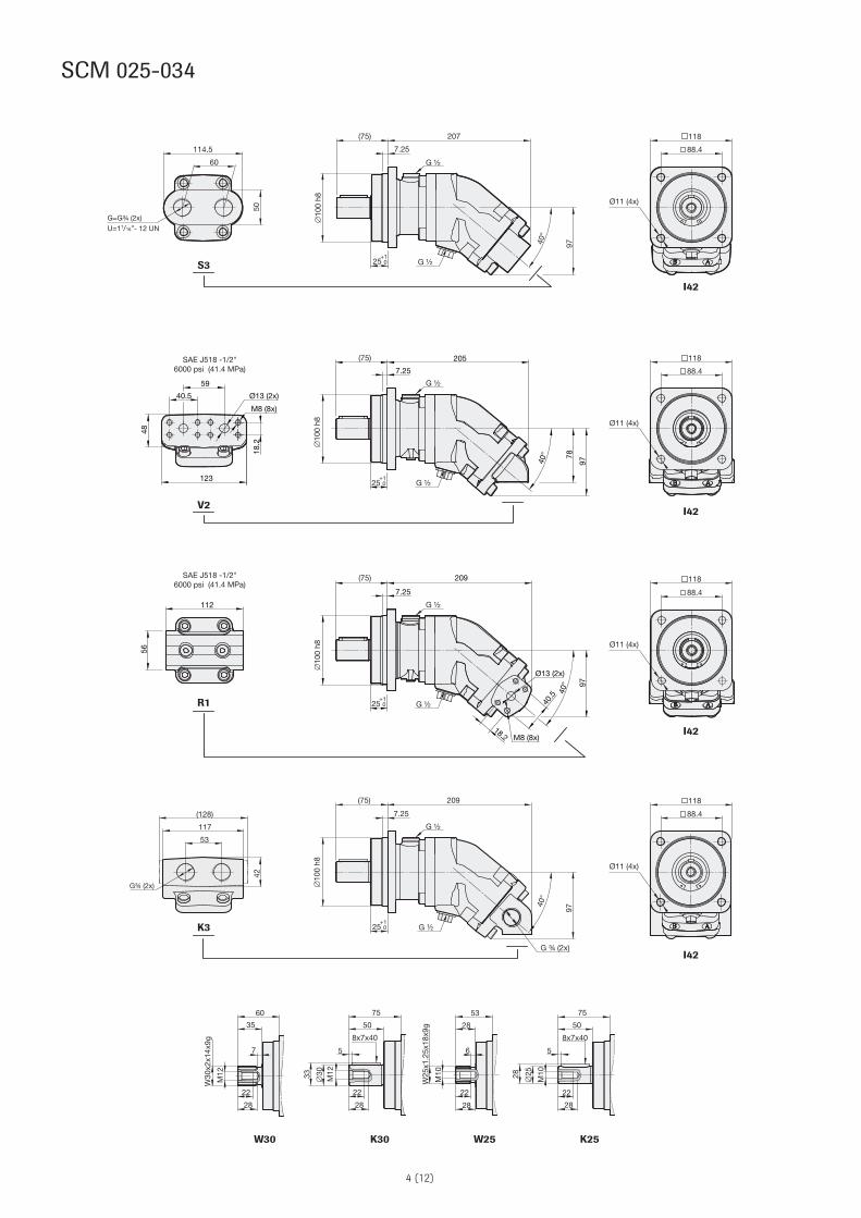
SCM 040-064
7.25
(92)
∅12
5 h8
242
40°
109
32+10
113.2
142.5
7.25
(92)
∅12
5 h8
240
40°
109
32+10
146.5
5459
75
153
75
23.8
23.8
50.8
Ø19 (2x)
Ø13.5 (4x)
50.8
8x10x50
W35
x2x1
6x9g
∅3538
M12
5
60
92
22
28
8
41
73
8x7x50
W32
x2x1
4x9g
∅30
M12
22
28
33
5
60
92
7
35
67
113.2
142.5
Ø13.5 (4x)
113.2
142.5
Ø13.5 (4x)
7.25
(92)
∅12
5 h8
70.8
248
40° 11
5
M10 (8x)
32+10
G ½
G ½
G ½
G ½
G ½
G ½
M=M10 (8x)U= 3/8”- 16 UNC-2B (8x)
M10 (8x) Ø19 (2x)
M12
22
28
M12
28
W30
x2x1
4x9g
7
35
67
K30W32 W30K35W35
S2
I43
I43
I43
R1
V2
153
50.8
∅19 (2
x)
23.8
22
M12
22
28
SAE J518 -3/4"6000 psi (41.4 MPa)
SAE J518 -3/4"6000 psi (41.4 MPa)
SAE J518 -3/4"6000 psi (41.4 MPa)

6 (12)
12x8x56
32
7.25
(102) 268
∅4043
7
70
102
W40
x2x1
8x9g
8
45
77
W35
x2x1
6x9g
8
40
72
48
Ø13.5 (4x)
+10
32
7.25
(102) 264
40°
130
127.3
160
27.8Ø25 (2x)
Ø25 (2x)
57.2
88
143
86
Ø13.5 (4x)
127.3
160
+10
G ½
G ½
G ½
G ½
G ½
G ½
G ½
G ½
M = M12 (8x)U = 7/16”- 14 UNC-2B (8x)
S1
I44
I44
I44
I44
R1
V127.8
57.2
75
136
89
7.25
288
40°
127
32
(102)
+10
∅14
0 h8
V2
72 255
7.25
∅14
0 h8
57.2
27.8
58
M12 (8x)
M12 (8x)
84
166
∅25 (2x)
32+10
40°
125
∅14
0 h8
∅14
0 h8
40°
M12 (8x)
57.2
∅25 (2
x)
27.8
81
132
160
22
28
M12
M16 36
48
M16 36
W35K40W40
SAE J518 -1"6000 psi (41.4 MPa)
SAE J518 -1"6000 psi (41.4 MPa)
SAE J518 -1"6000 psi (41.4 MPa)
SAE J518 -1"6000 psi (41.4 MPa)
Ø13.5 (4x)
127.3
160
Ø13.5 (4x)
127.3
160
SCM 084-090
7 (12)
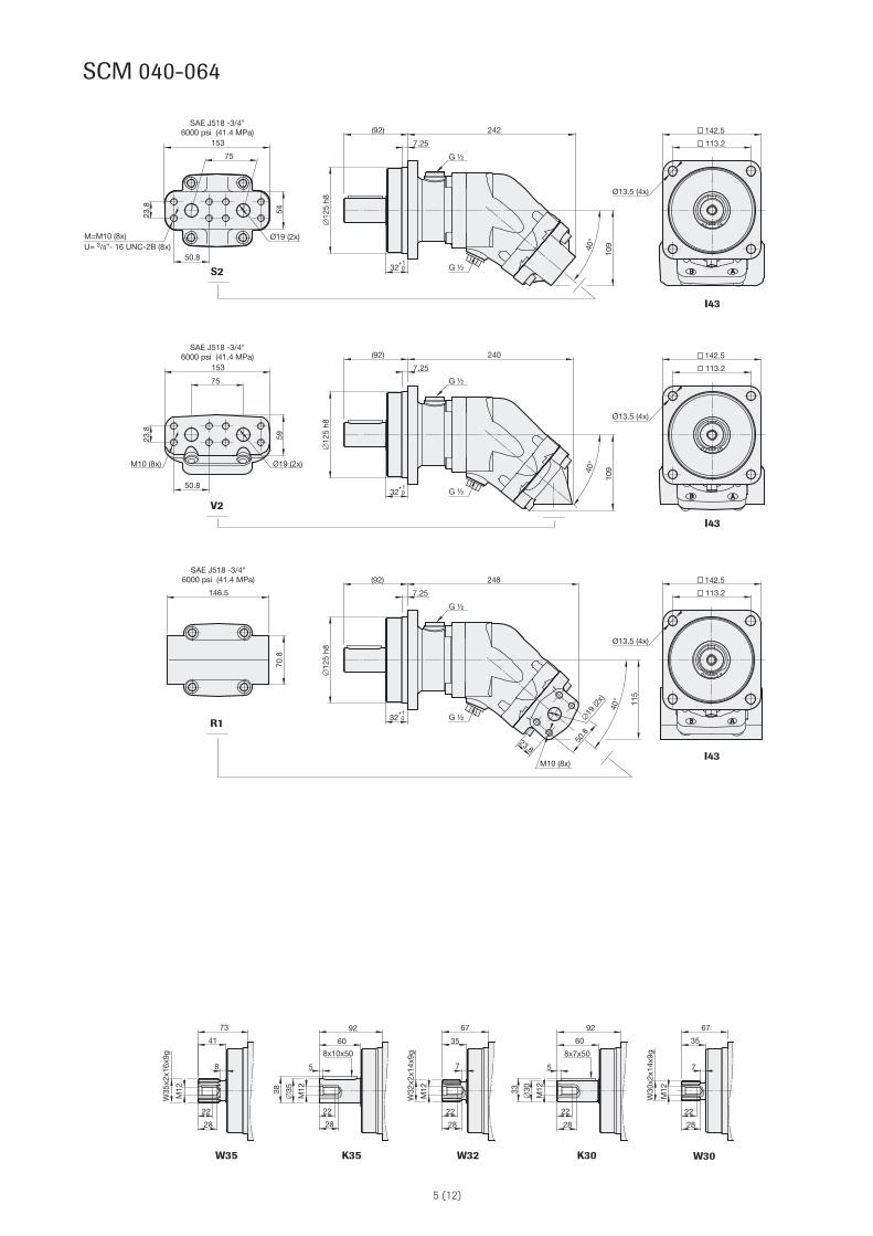
SCM 108
14x9x63
7.25
(120) 268
∅16
0 h8
40
M16
∅45
48.5
8.5
80
120
36
48
M16 36
48
8
50
90
36
48
8
45
85
W45
x2x2
1x9g
M16
W40
x2x1
8x9g
27.8
57.2
75
136
89
+10
7.25
(120)
(120)
288
∅16
0 h8
∅16
0 h8
40
40°
127
+10
K45 W40W45
S1
R1
V1
I45
I45
I45
I45
7.25
(120) 264
∅16
0 h8
40
40°
130
141.4
180
27.8
57.2
88
143
86
+10
G ½
G ½
G ½
G ½
G ½
G ½
G ½
G ½
Ø17.5 (4x)
Ø25 (2x)
Ø25 (2x)
141.4
180
Ø17.5 (4x)
141.4
180
Ø17.5 (4x)
141.4
180
Ø17.5 (4x)
40°
M12 (8x)
57.2
∅25 (2
x)
27.8
81
132
160
M=M12 (8x)U= 7/16”- 14 UNC-2B (8x)
M12 (8x)
V2
∅25 (2x)
SAE J518 -1"6000 psi (41.4 MPa)
SAE J518 -1"6000 psi (41.4 MPa)
SAE J518 -1"6000 psi (41.4 MPa)
SAE J518 -1"6000 psi (41.4 MPa)
7.25
255
84
166
58
27.8
57.2
M12 (8x)
40°
125
40+10
107

8 (12)
SCM 130
I45
7.25
(120) 280
∅16
0 h8
40+10
R1
40°
M14 (8x)
66.7
∅32 (2
x)
31.8
95
143
164
SAE J518 -1 1/4"6000 psi (41.4 MPa)
14x9x63
M16
∅45
48.5
8.5
80
120
36
48
M16 36
48
8
50
90
36
48
8
45
85
W45
x2x2
1x9g
M16
W40
x2x1
8x9g
27.8
57.2
75
136
89
7.25
(120)
(120)
288
∅16
0 h8
∅16
0 h8
40
40°
127
+10
K45 W40W45
S1
V1
I45
I45
I45
7.25
(120) 264
∅16
0 h8
40
40°
130
141.4
180
27.8
57.2
88
143
86
+10
G ½
G ½
G ½
G ½
G ½
G ½
G ½
G ½
Ø17.5 (4x)
Ø25 (2x)
Ø25 (2x)
141.4
180
Ø17.5 (4x)
141.4
180
Ø17.5 (4x)
141.4
180
Ø17.5 (4x)
M=M12 (8x)U= 7/16”- 14 UNC-2B (8x)
M12 (8x)
V2
∅25 (2x)
SAE J518 -1"6000 psi (41.4 MPa)
SAE J518 -1"6000 psi (41.4 MPa)
SAE J518 -1"6000 psi (41.4 MPa)
7.25
255
84
166
58
27.8
57.2
M12 (8x)
40°
125
40+10
107

9 (12)
A F F20° 20°
B
°C 1000 2000 3000 4000 5000 6000 7000 8000 9000
012-034 N 75 0.55 0.27 0.18 0.14 0.11 0.09 0.08 0.07 0.06 H 75 2.46 1.23 0.82 0.61 0.49 0.41 0.35 0.31 0.27 V 90 0.55 0.27 0.18 0.14 0.11 0.09 0.08 0.07 0.06
040-064 N 75 0.55 0.27 0.18 0.14 0.11 0.09 0.08 H 75 2.46 1.23 0.82 0.61 0.49 0.41 0.35 V 90 0.55 0.27 0.18 0.14 0.11 0.09 0.08
084-130 N 75 0.38 0.19 0.13 0.10 0.08 0.06 H 75 1.72 0.86 0.57 0.43 0.34 0.29 V 90 0.38 0.19 0.13 0.10 0.08 0.06
D
Fr
Fa+
Fa-
012 017 025 034 040 047 056 064 084 090 108 130kN 7 7 8 8 8.5 8.5 9 9 12 12.5 12.5 13
mm 45 45 50 50 60 60 60 60 65 65 70 70
kN 3 3 3 3 4 4 4 4 5 5 5 5
kN 4 5 7 7 7 7 10 11 13 14 16 19
kN 4 5 7 7 7 7 10 11 13 14 16 19
kN 0 0 0 0 0 0 0 0 0 0 0 0
General instructions
PressureClockwise
rotation
PressureAnticlockwiserotation
Temp. Max. housing pressure MPa at rpm Motor SCM Code
Optimal force directionof radial load
Shaft loads
The life of the motor is highly dependent on the bearing life. The bearings are affected by operating conditions such as speed, pressure, oil viscosity and filtration.
External load on the shaft, as well as its size, direction and location also affects the bearing life.
Choice of shaft seal
SCM ISOMax recommended shaft loads
Fr (radial) max1
Distance D (to point of force)
Fa (axial) + (at standstill/ 0 bar pressure) max
Fa (axial) - (at standstill/ 0 bar pressure) max
Fa (axial) + (at 400 bar pressure) max2
Fa (axial) - (at 400 bar pressure) max2
¹) Fr (radial) max; Calculation based on running conditions: 300 bar / 2000 rpm¹) Fr (radial) max; Calculation based on optimal force direction (Fr max will be lower in other force directions) ¹) Fr (radial) max; In running conditions higher than 300 bar and/or 2000 rpm the max limits for Fr (radial) max will be lower
²) Fa (axial) + Will increase bearing life²) Fa (axial) - Will decrease bearing life
For other forces, please contact Sunfab for advice.
The drainage oil should have a maximum temperature of 75 °C with a Nitrile shaft seal and 90 °C with a Viton shaft seal. These temperatures must not be exceeded.The housing pressure must be equal to or greater than the external pressure on the shaft seal.
Code according to page 2, Versions, main data
Factors affecting the choice of shaft seal include the hydraulic motor housing pressure and the drainage oil temperature.

10 (12)
Q
012-034 2-8 ≥ 2800 040-064 4-10 ≥ 2500 084-130 6-12 ≥ 2200
Temperatures/Housing cooling
Excessive system temperature reduces the life of the shaft seal and can lower the oil viscosity below the re-commended level. A system temperature of 60 °C and a drain flow temperature of 90 °C must not be exceeded. Cooling/flushing of the motor housing can be needed to keep the drain flow temperature at an acceptable level.
Suggested flow: Motor SCM Flushing l/min Cont. RPM
Installation
• The motor housing should be filled with oil to at least 50% before starting.
• The drainage pipe should be connected to topmost drainage outlet.
• The other end of the pipe should be connected to the oil tank at a point below the oil level.
Qflush
Qflush
Qflush
Housing flushing can be built up with the help of a flushing valve or taken directly from the return line. When the return pressure is too low this is compensated for by a counter pressure valve.The tank line is connected to the highest point as in the figure.
Simplified circuits
Flus
hing
val
ve
Cou
nter
pres
sure
valv
e
Counterpressurevalve

11 (12)
D x n1000 x ηv
Q x 1000 x ηv
D
D x ∆p x ηhm
6.3
Q x ∆p x ηt
60
D = displacement, cm3⁄revolution
n = speed, revolution⁄min
P = power, kW
Q = flow rate, litres⁄min
ηv = volumetric efficiency
ηhm = hydraulic-mechanical efficiency
ηt = overall efficiency = ηv x ηhm
M = torque, Nm
∆p = pressure difference between the hydraulic motor inlet and outlet, MPa
Useful formulaes
Required flow rate Q = litres⁄min.
Speed n = RPM
Torque M = Nm
Power P = kW
Hydraulic fluids
High performance oils meeting ISO specifications – such as HM, DIN 51524-2 HLP, or better – must be used. A min. viscosity of 10 cSt is required to keep the lubrica-tion at a safe level.
The ideal viscosity is 20 - 40 cSt.
Additional technical data
Noise levels and bearing life calculations available on re-quest. Please contact Sunfab!
Piping
Recommended oil velocity in pressure line max. 7 m/sec
Filtering
Cleanliness according to ISO norm 4406, code16/13.

12 (12)
WARNING
When the motor is in use:
1. Do not touch the pressure pipe
2. Beware of rotating parts
3. The motor and pipes can reach high temperatures
320
1GB
1301
Pro
duce
d in
Sw
eden
by
AL
Rek
lam
ww
w.a
lrekl
am.s
e
Sunfab Hydraulics AB, Box 1094, SE-824 12 Hudiksvall, Sweden. Phone: +46 650-367 00, Fax: +46 650-367 27, E-mail: [email protected] Web: www.sunfab.com
Sunfab reserves the right to make changes in design and dimensions without notice. Printing and typesetting errors reserved.