Bent Axis Piston Motors SCM Series - dhc-hydraulic.nl plunjer motor SCM... · Bent Axis Piston...
24
HT 17 / D / 102 / 0909 / E Bent Axis Piston Motors SCM Series HYDRAULIC COMPONENTS HYDROSTATIC TRANSMISSIONS GEARBOXES - ACCESSORIES ISO SAE M2
-
Upload
nguyenhanh -
Category
Documents
-
view
237 -
download
2
Transcript of Bent Axis Piston Motors SCM Series - dhc-hydraulic.nl plunjer motor SCM... · Bent Axis Piston...
HT 17 / D / 102 / 0909 / E
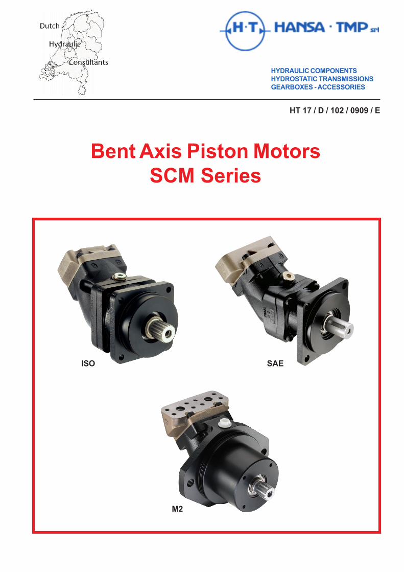
Bent Axis Piston MotorsSCM Series
HYDRAULIC COMPONENTS
HYDROSTATIC TRANSMISSIONS
GEARBOXES - ACCESSORIES
ISO SAE
M2
HT 17 / D / 102 / 0909 / E Pag. 3
Bent Axis Piston Motors SCM Series
SCM 010 - 130 - ISO - General Information.....................................SCM 010 - 130 - ISO - Technical Information..................................SCM 010 - 130 - ISO - Versions, Main Data....................................SCM 010 - 130 - ISO - Choice of Shaft Seal...................................SCM 010 - 020 - ISO - Installation Drawings...................................SCM 025 - 034 - ISO - Installation Drawings...................................SCM 042 - 064 - ISO - Installation Drawings...................................SCM 084 - ISO - Installation Drawings............................................SCM 108 - 130 - ISO - Installation Drawings...................................SCM 010 - 130 - ISO - General Instructions....................................
SCM 012 - 130 - SAE - General Information....................................SCM 012 - 130 - SAE - Technical Information.................................SCM 012 - 130 - SAE - Versions, Main Data...................................SCM 012 - 130 - SAE - Choice of Shaft Seal..................................SCM 012 - 130 - SAE - Installation Drawings..................................SCM 012 - 130 - SAE - General Instructions...................................
SCM 012 - 034 - SAE B2 - General and Technical Informations.....
SCM 034 - 108 - M2 - General Information......................................SCM 034 - 108 - M2 - Technical Information....................................SCM 034 - 108 - M2 - Versions, Main Data......................................SCM 034 - 108 - M2 - Choice of Shaft Seal.....................................SCM 034 - 108 - M2 - Installation Drawings....................................SCM 034 - 108 - M2 - General Instructions.....................................
445567891011 - 12
131314141516 - 17
18 - 19
202021212223 - 24
Index
Pag. 4 HT 17 / D / 102 / 0909 / E
Bent Axis Piston Motors SCM Series
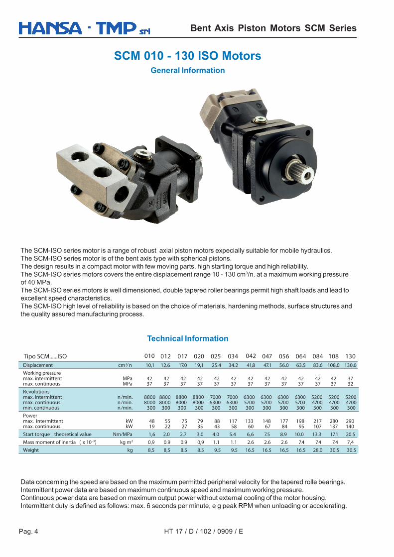
SCM 010 - 130 ISO MotorsGeneral Information
The SCM-ISO series motor is a range of robust axial piston motors expecially suitable for mobile hydraulics.The SCM-ISO series motor is of the bent axis type with spherical pistons.The design results in a compact motor with few moving parts, high starting torque and high reliability.The SCM-ISO series motors covers the entire displacement range 10 - 130 cm3/n. at a maximum working pressureof 40 MPa.The SCM-ISO series motors is well dimensioned, double tapered roller bearings permit high shaft loads and lead toexcellent speed characteristics.The SCM-ISO high level of reliability is based on the choice of materials, hardening methods, surface structures andthe quality assured manufacturing process.
Data concerning the speed are based on the maximum permitted peripheral velocity for the tapered rolle bearings.Intermittent power data are based on maximum continuous speed and maximum working pressure.Continuous power data are based on maximum output power without external cooling of the motor housing.Intermittent duty is defined as follows: max. 6 seconds per minute, e g peak RPM when unloading or accelerating.
Technical Information
012 017 025 034 047 056 064 084 108 130 10,1 12.6 17.0 19,1 25.4 34.2 41,8 47.1 56.0 63.5 83.6 108.0 130.0
42 42 42 42 42 42 42 42 42 42 42 42 37 37 37 37 37 37 37 37 37 37 37 37 37 32
8800 8800 8800 8800 7000 7000 6300 6300 6300 6300 5200 5200 5200 8000 8000 8000 8000 6300 6300 5700 5700 5700 5700 4700 4700 4700
300 300 300 300 300 300 300 300 300 300 300 300 300
48 55 75 79 88 117 133 148 177 198 217 280 290 19 22 27 35 43 58 60 67 84 95 107 137 140
1,6 2.0 2.7 3,0 4.0 5.4 6 , 6 7.5 8.9 10.0 13.3 17.1 20.5
0,9 0.9 0.9 0,9 1.1 1.1 2.6 2.6 2.6 7.4 7.4 7.4 7,4
8,5 8,5 8.5 8.5 9.5 9.5 16.5 16.5 16,5 16.5 28.0 30.5 30.5
Displacement cm3⁄ nWorking pressuremax. intermittent MPamax. continuous MPaRevolutionsmax. intermittent n ⁄min.max. continuous n ⁄min.min. continuous n ⁄min.Powermax. intermittent kWmax. continuous kWStart torque theoretical value Nm⁄MPaMass moment of inertia ( x 10 -3) kg m2
Weight kg
Tipo SCM......ISO 010 042020
HT 17 / D / 102 / 0909 / E Pag. 5
Bent Axis Piston Motors SCM Series
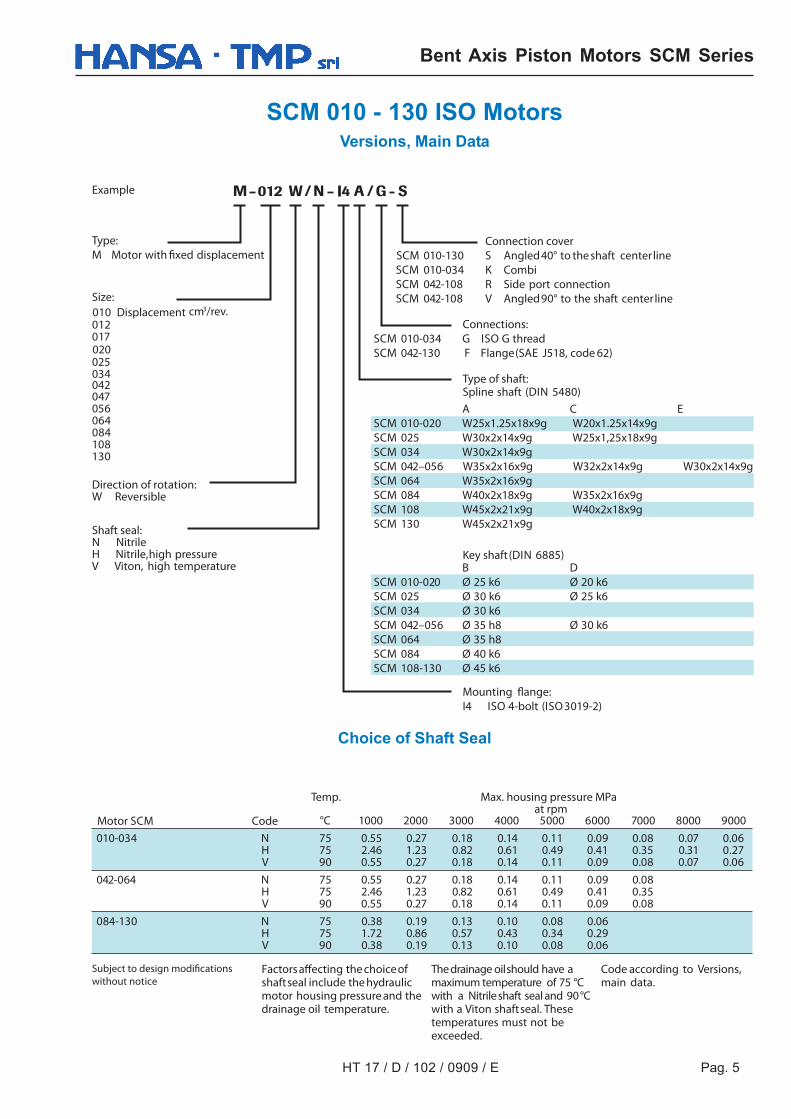
SCM 010 - 130 ISO MotorsVersions, Main Data
°C 1000 2000 3000 4000 5000 6000 7000 8000 9000
010-034 N 75 0.55 0.27 0.18 0.14 0.11 0.09 0.08 0.07 0.06H 75 2.46 1.23 0.82 0.61 0.49 0.41 0.35 0.31 0.27V 90 0.55 0.27 0.18 0.14 0.11 0.09 0.08 0.07 0.06
042-064 N 75 0.55 0.27 0.18 0.14 0.11 0.09 0.08H 75 2.46 1.23 0.82 0.61 0.49 0.41 0.35V 90 0.55 0.27 0.18 0.14 0.11 0.09 0.08
084-130 N 75 0.38 0.19 0.13 0.10 0.08 0.06H 75 1.72 0.86 0.57 0.43 0.34 0.29V 90 0.38 0.19 0.13 0.10 0.08 0.06
SCM 010-130SCM 010-034SCM 042-108SCM 042-108
SCM 010-034 GSCM 042-130 F
A C ESCM 010-020 W25x1.25x18x9g W20x1.25x14x9gSCM 025 W30x2x14x9g W25x1,25x18x9gSCM 034 W30x2x14x9gSCM 042–056 W35x2x16x9g W32x2x14x9g W30x2x14x9gSCM 064 W35x2x16x9gSCM 084 W40x2x18x9g W35x2x16x9gSCM 108 W45x2x21x9g W40x2x18x9gSCM 130 W45x2x21x9g
B DSCM 010-020 Ø 25 k6 Ø 20 k6SCM 025 Ø 30 k6 Ø 25 k6SCM 034 Ø 30 k6SCM 042–056 Ø 35 h8 Ø 30 k6SCM 064 Ø 35 h8SCM 084 Ø 40 k6SCM 108-130 Ø 45 k6
Example
Type:
M Motor with displacement
Size:
012cm3/rev.
017
025034
047056064084108130
Direction of rotation:W Reversible
Shaft seal:N NitrileH Nitrile,high pressureV Viton, high temperature
Connection cover
S Angled40° to the shaft centerlineK CombiR Side port connectionV Angled90° to the shaft centerline
Connections:
ISO G threadFlange(SAE J518, code 62)
Type of shaft:Spline shaft (DIN 5480)
Key shaft(DIN 6885)
Mount
I4 ISO 4-bolt (ISO3019-2)
Factors ecting the choiceofshaftseal include the hydraulicmotor housing pressure and thedrainage oil temperature.
cations
without notice
Temp. Max. housing pressure MPaat rpm
Motor SCM Code
Thedrainage oilshould have amaximum temperature of 75 °Cwith a Nitrileshaft seal and 90°Cwith a Viton shaftseal. Thesetemperatures must not beexceeded.
Code according to Versions,main data.
010 Displacement
020
042
Choice of Shaft Seal
Pag. 6 HT 17 / D / 102 / 0909 / E
Bent Axis Piston Motors SCM Series
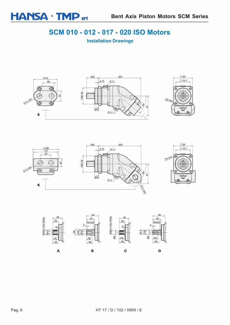
SCM 010 - 012 - 017 - 020 ISO Motors Installation Drawings
(2x)
G 1 2
G3 4
80 h
8
20
5.75
(60) 207
70.7
95
9 (4x)
8x7x32 6x6x32
W25
x1.2
5x18
x9g
W20
x1.2
5x14
x9g
M10
28
M10
22
28
M6
22
28
M6
22
28
2528 20
22.5
4
40
4
40
60 60
6
28
48
6
28
48
+10
G
40°
97
80 h
8
20
5.75
(60) 209
70.7
95
9 (4x)
+10
40°
97
60
114.5
50
1 2
G 1 2
G 1 2
22
53117
42
(128)
(2x)
G3 4
(2x)
G3
4
HT 17 / D / 102 / 0909 / E Pag. 7
Bent Axis Piston Motors SCM Series
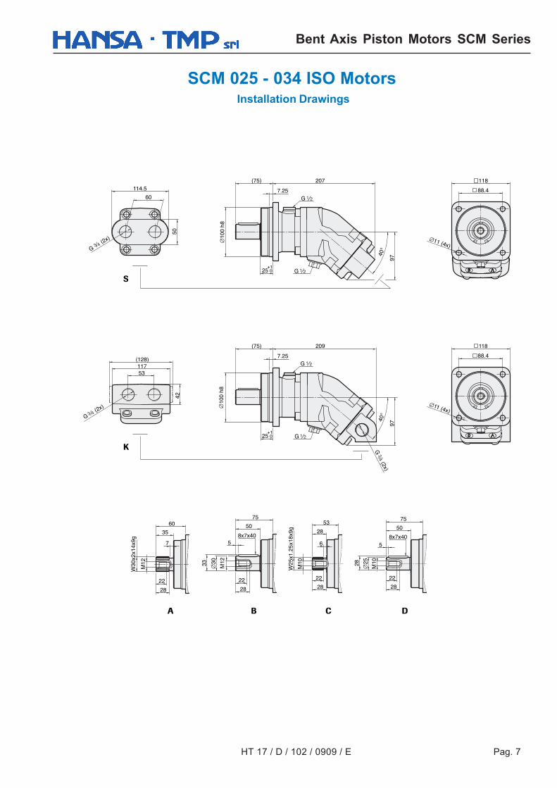
SCM 025 - 034 ISO Motors Installation Drawings
G 1 2
(2x)
G3 4
100
h8
(75) 209
7.25
25+10
40°
97
88.4
118
11 (4x)
60
114.5
50
8x7x40
W30
x2x1
4x9g
M123033
5
50
75
22
28
M12
22
28
7
35
60
G 1 2
(2x) 3
G4
8x7x406
28
53
M10
W25
x1.2
5x18
x9g
2528
5
50
75
22
28
M10
22
28
53117
(128)
42
100
h8
(75) 207
7.25
25+10
40°
97
88.4
118
11 (4x)
G 1 2
G 1 2
(2x)
G3
4
Pag. 8 HT 17 / D / 102 / 0909 / E
Bent Axis Piston Motors SCM Series
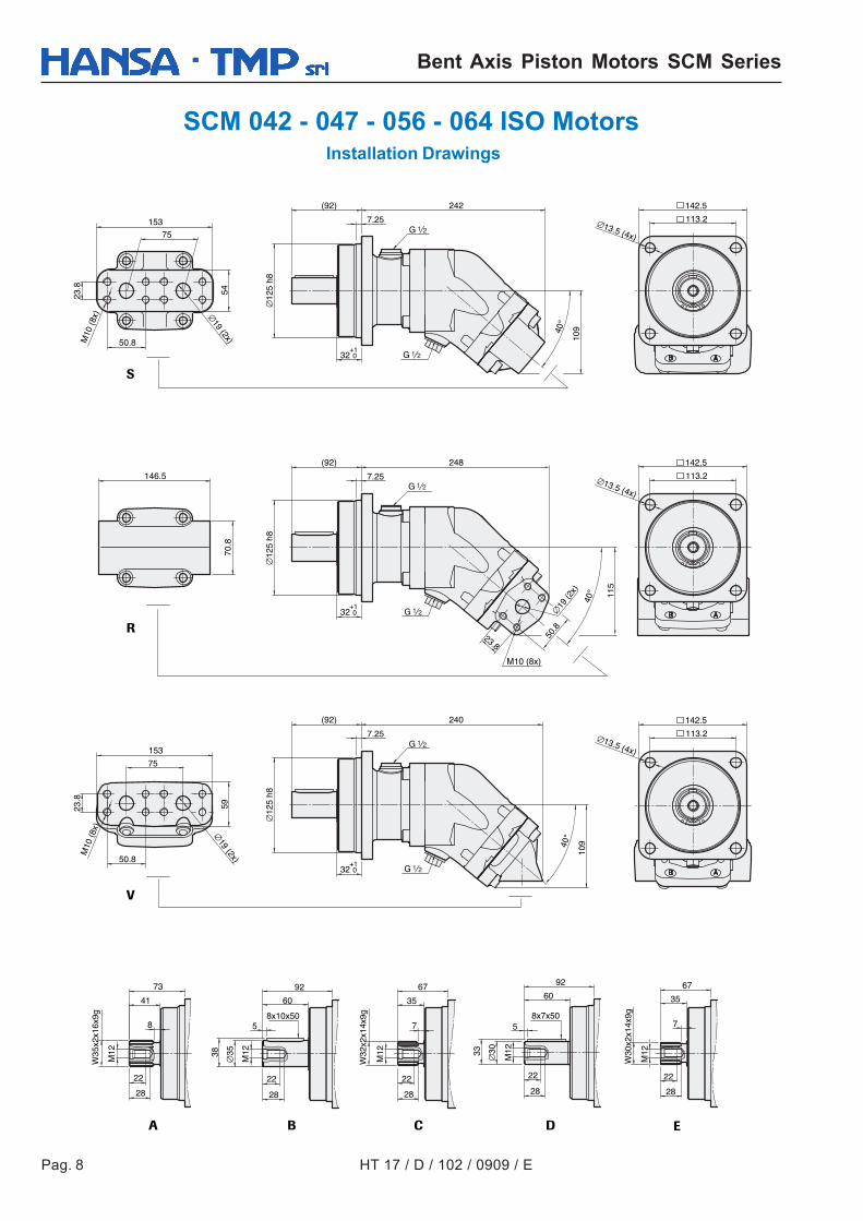
SCM 042 - 047 - 056 - 064 ISO Motors Installation Drawings
G 1 2
7.25
(92)
125
h8
242
40°
109
32+10
113.2
142.5
13.5 (4x)
7.25
(92)
125
h8
240
40°
109
32+10
146.5
5459
75
153
75
23.8
23.8
50.8
50.8
19 (2x)19 (2x)
M10
(8x)
M10
(8x)
8x10x50
W35
x2x1
6x9g
3538
M12
5
60
92
22
28
8
41
73
8x7x50
W32
x2x1
4x9g
30
M12
22
28
33
5
60
92
7
35
67
7.25
(92)
125
h8
70.8
248
40° 11
5
M10 (8x)
32+10
113.2
142.5
13.5 (4x)
113.2
142.5
13.5 (4x)
G 1 2
G 1 2
G 1 2
G 1 2
G 1 2
M12
22
28
M12
28
W30
x2x1
4x9g
7
35
67
153
50.8
19 (2
x)
23.8
22
M12
22
28
HT 17 / D / 102 / 0909 / E Pag. 9
Bent Axis Piston Motors SCM Series
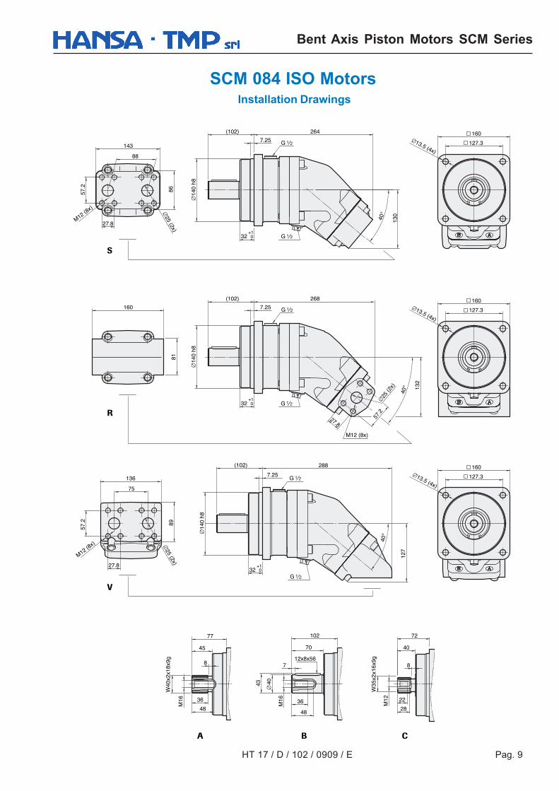
SCM 084 ISO Motors Installation Drawings
12x8x56
32
7.25
(102) 268
127.3
160
4043
7
70
102
W40
x2x1
8x9g 8
45
77
W35
x2x1
6x9g
8
40
72
48
13.5 (4x)
127.3
160
13.5 (4x)
+10
32
7.25
(102) 264
40°
130
127.3
160
27.8
57.2
M12 (8x)
88
143
86
13.5 (4x)
+10
G 1 2
G 1 2
G 1 2
G 1 2
27.8
57.2
M12 (8x)
75
136
89
25 (2x)
7.25
288
40°
127
25 (2x)
32
(102)
+10
140
h8
G 1 2
G 1 2
140
h814
0 h8
40°
M12 (8x)
57.2
25 (2
x)
27.8
81
132
160
22
28
M12
M16 36
48
M16 36
Pag. 10 HT 17 / D / 102 / 0909 / E
Bent Axis Piston Motors SCM Series
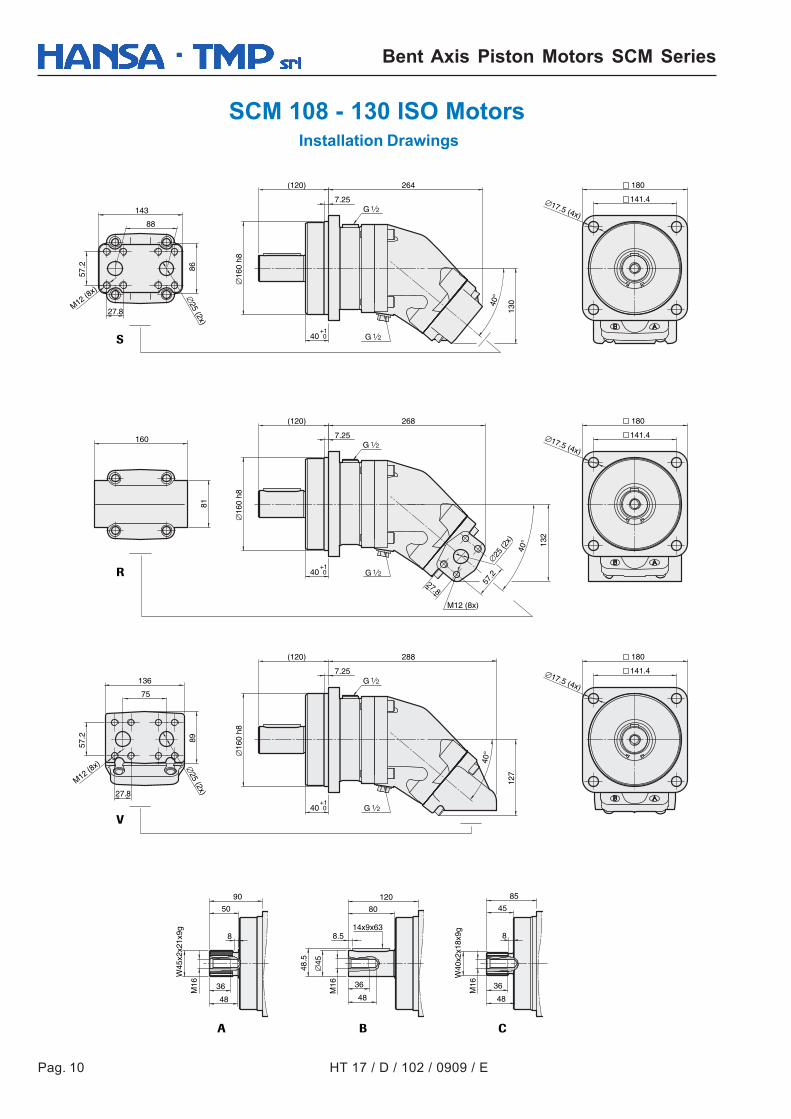
SCM 108 - 130 ISO Motors Installation Drawings
HT 17 / D / 102 / 0909 / E Pag. 11
Bent Axis Piston Motors SCM Series
SCM 010 - 130 ISO MotorsGeneral Instructions
AF F20° 20°
B
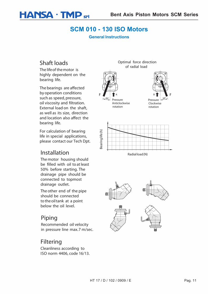
Shaft loadsThe lifeof the motor ishighly dependent on thebearing life.
The bearings are affectedby operation conditionssuch as speed, pressure,oil viscosity and filtration.External load on the shaft,as well as its size, directionand location also affect thebearing life.
For calculation of bearinglife in special applications,please contact our Tech Dpt.
InstallationThe motor housing shouldbe filled with oil to at least50% before starting. Thedrainage pipe should beconnected to topmostdrainage outlet.
The other end of the pipeshould be connectedto the oil tank at a pointbelow the oil level.
PipingRecommended oil velocityin pressure line max.7 m/sec.
FilteringCleanliness according toISO norm 4406, code 16/13.
Radial load(N)
Bear
ing
life
(h)
PressureClockwiserotation
PressureAnticlockwiserotation
Optimal force directionof radial load
Pag. 12 HT 17 / D / 102 / 0909 / E
Bent Axis Piston Motors SCM Series
SCM 010 - 130 ISO MotorsGeneral Instructions
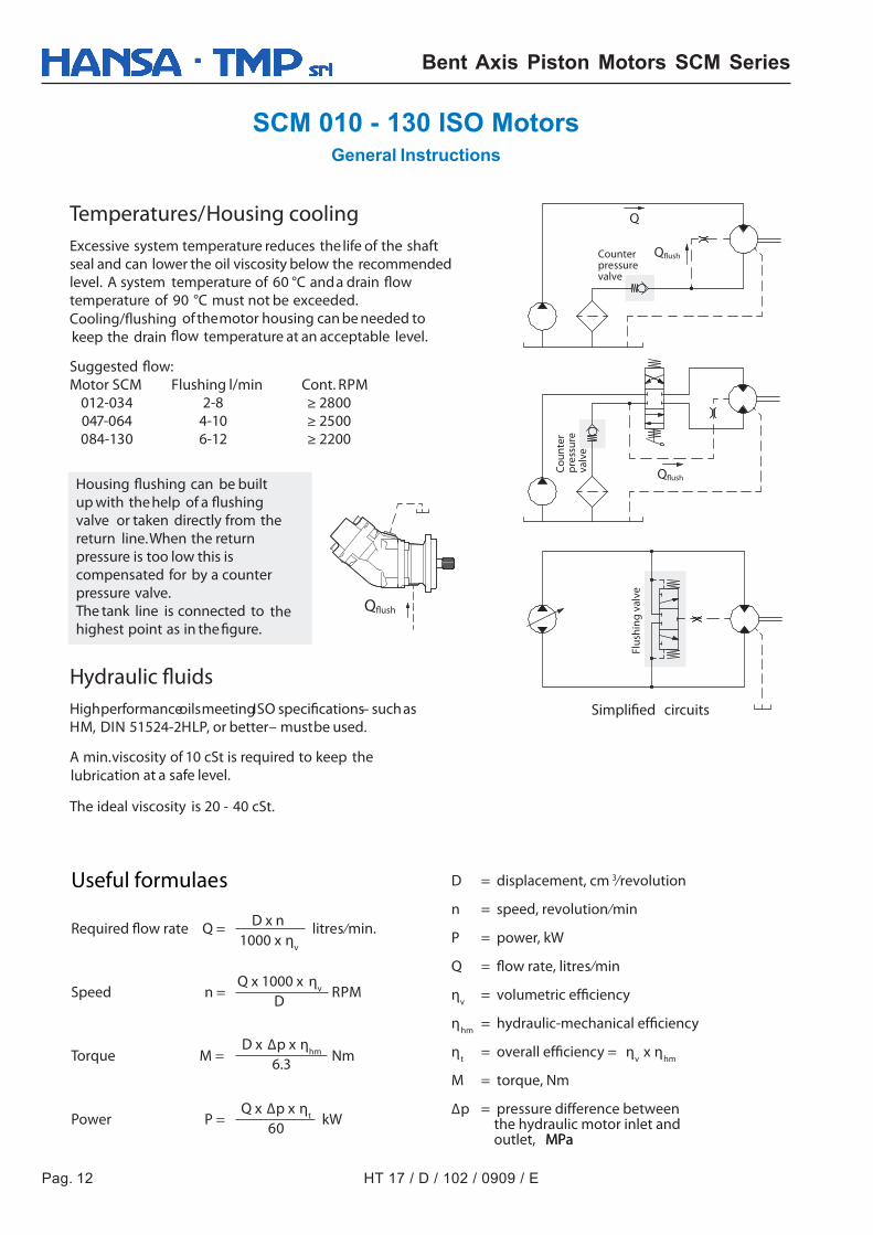
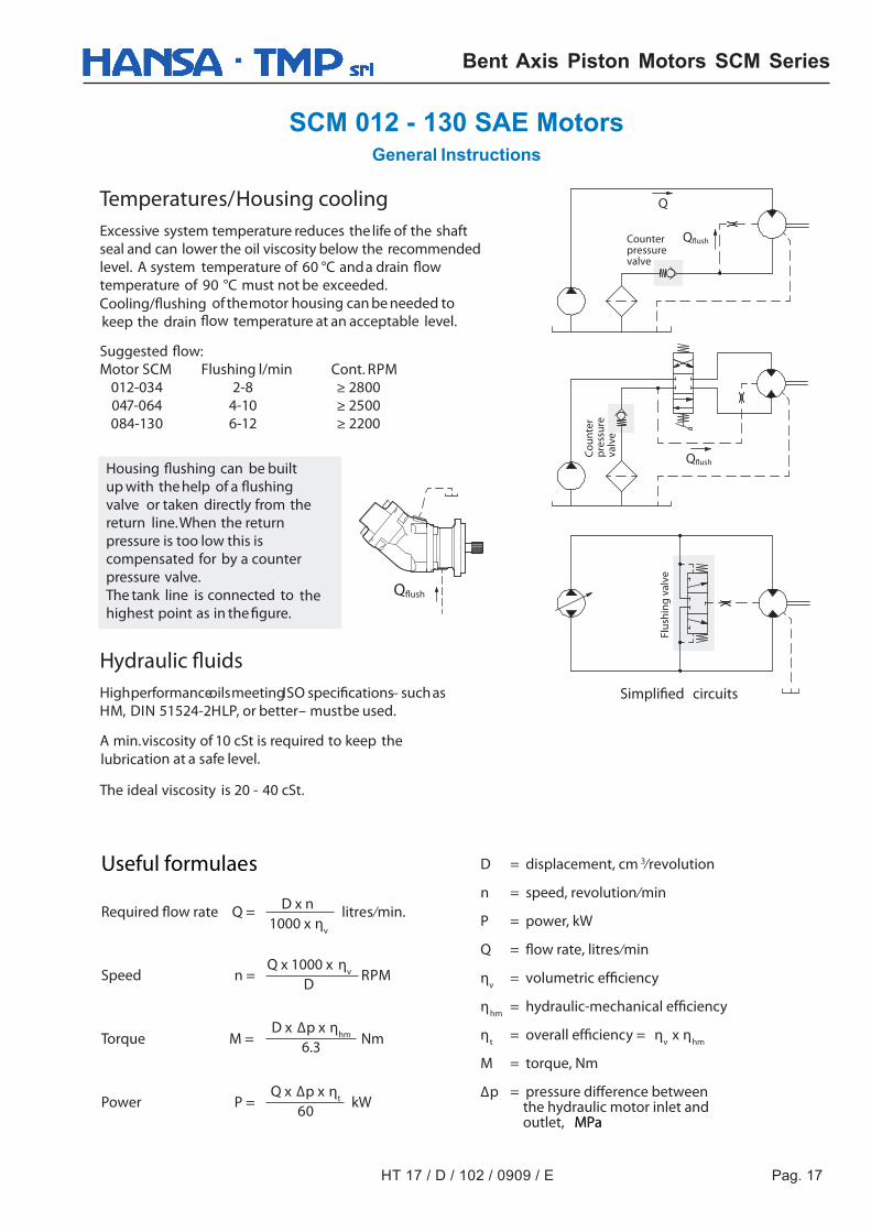
Temperatures/Housing coolingExcessive system temperature reduces the life of the shaftseal and can lower the oil viscosity below the recommendedlevel. A system temperature of 60 °C anda drain flowtemperature of 90 °C must not be exceeded.Cooling/flushing of themotor housing can be needed tokeep the drain flow temperature at an acceptable level.
Suggested flow:Motor SCM Flushing l/min Cont. RPM 012-034 2-8 ≥ 2800 047-064 4-10 ≥ 2500 084-130 6-12 ≥ 2200
Hydraulic fluidsHighperformanceoilsmeetingISO specifications– suchasHM, DIN 51524-2HLP, or better– mustbe used.
A min.viscosity of 10 cSt is required to keep thelubrication at a safe level.
The ideal viscosity is 20 - 40 cSt.
Useful formulaes
Required flow rate Q = litres ⁄min.
Speed n = RPM
Torque M = Nm
Power P = kW
D = displacement, cm 3⁄revolution
n = speed, revolution ⁄min
P = power, kW
Q = flow rate, litres ⁄min
ηv = volumetric efficiency
ηhm = hydraulic-mechanical efficiency
ηt = overall efficiency = ηv x ηhm
M = torque, Nm
Δp = pressure difference between the hydraulic motor inlet and outlet, MPaMPa
D x n1000 x ηv
Q x 1000 x ηv
D
D x Δp x ηhm
6.3
Q x Δp x ηt
60
Q
Qflush
Qflush
Qflush
Housing flushing can be builtup with the help of a flushingvalve or taken directly from thereturn line.When the returnpressure is too low this iscompensated for by a counterpressure valve.The tank line is connected to thehighest point as in the figure.
Simplified circuits
Flus
hing
val
ve
Coun
ter
pres
sure
valv
e
Counterpressurevalve
HT 17 / D / 102 / 0909 / E Pag. 13
Bent Axis Piston Motors SCM Series
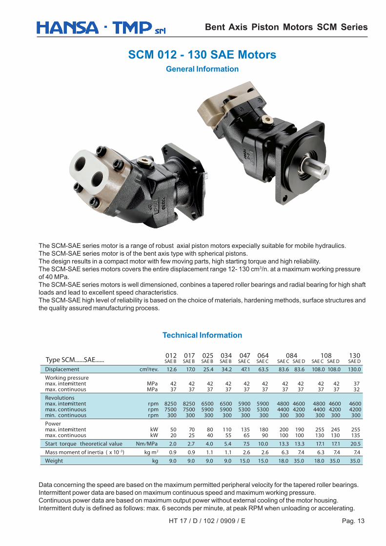
SCM 012 - 130 SAE MotorsGeneral Information
The SCM-SAE series motor is a range of robust axial piston motors expecially suitable for mobile hydraulics.The SCM-SAE series motor is of the bent axis type with spherical pistons.The design results in a compact motor with few moving parts, high starting torque and high reliability.The SCM-SAE series motors covers the entire displacement range 12- 130 cm3/n. at a maximum working pressureof 40 MPa.The SCM-SAE series motors is well dimensioned, conbines a tapered roller bearings and radial bearing for high shaftloads and lead to excellent speed characteristics.The SCM-SAE high level of reliability is based on the choice of materials, hardening methods, surface structures andthe quality assured manufacturing process.
Data concerning the speed are based on the maximum permitted peripheral velocity for the tapered roller bearings.Intermittent power data are based on maximum continuous speed and maximum working pressure.Continuous power data are based on maximum output power without external cooling of the motor housing.Intermittent duty is defined as follows: max. 6 seconds per minute, at peak RPM when unloading or accelerating.
Technical Information
012 017 025 034 047 064 084 108 130SAE B SAE B SAE B SAE B SAE C SAE C SAE C SAE D SAE C SAE D SAE D
12.6 17.0 25.4 34.2 47.1 63.5 83.6 83.6 108.0 108.0 130.0
42 42 42 42 42 42 42 42 42 42 37 37 37 37 37 37 37 37 37 37 37 32
8250 8250 6500 6500 5900 5900 4800 4600 4800 4600 4600 7500 7500 5900 5900 5300 5300 4400 4200 4400 4200 4200 300 300 300 300 300 300 300 300 300 300 300
50 70 80 110 135 180 200 190 255 245 255 20 25 40 55 65 90 100 100 130 130 135
2.0 2.7 4.0 5.4 7.5 10.0 13.3 13.3 17.1 17.1 20.5
0.9 0.9 1.1 1.1 2.6 2.6 6.3 7.4 6.3 7.4 7.4
9.0 9.0 9.0 9.0 15.0 15.0 18.0 35.0 18.0 35.0 35.0
Displacement cm3⁄rev.Working pressuremax. intermittent MPamax. continuous MPaRevolutionsmax. intermittent rpmmax. continuous rpmmin. continuous rpmPowermax. intermittent kWmax. continuous kWStart torque theoretical value Nm ⁄MPaMass moment of inertia ( x 10 -3) kg m2
Weight kg
Type SCM......SAE......
Pag. 14 HT 17 / D / 102 / 0909 / E
Bent Axis Piston Motors SCM Series
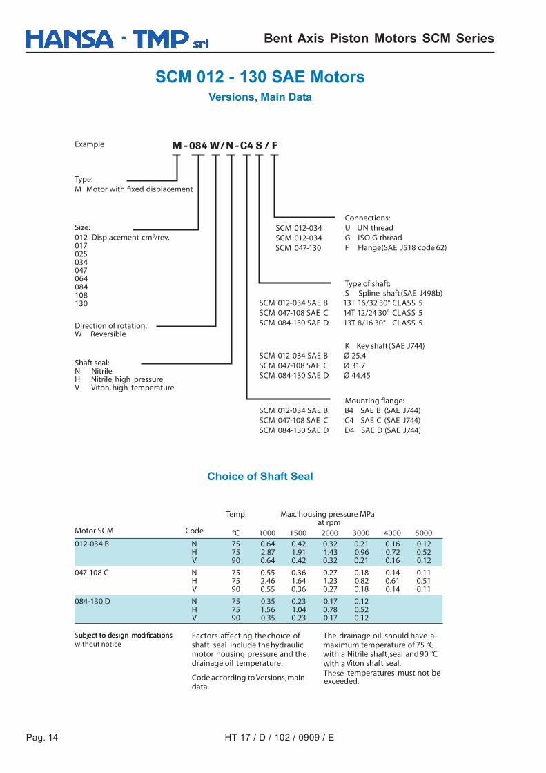
SCM 012 - 130 SAE MotorsVersions, Main Data
SCM 012-034 SCM 012-034
SCM 047-130
SCM 012-034 SAE B 13T 16/32 30° CLASS 5SCM 047-108 SAE C 14T 12/24 30° CLASS 5SCM 084-130 SAE D 13T 8/16 30° CLASS 5
SCM 012-034 SAE B Ø 25.4SCM 047-108 SAE C Ø 31.7 SCM 084-130 SAE D Ø 44.45
SCM 012-034 SAE B B4 SAE B (SAE J744)SCM 047-108 SAE C C4 SAE C (SAE J744)SCM 084-130 SAE D D4 SAE D (SAE J744)
°C 1000 1500 2000 3000 4000 5000012-034 B N 75 0.64 0.42 0.32 0.21 0.16 0.12
H 75 2.87 1.91 1.43 0.96 0.72 0.52 V 90 0.64 0.42 0.32 0.21 0.16 0.12
047-108 C N 75 0.55 0.36 0.27 0.18 0.14 0.11H 75 2.46 1.64 1.23 0.82 0.61 0.51V 90 0.55 0.36 0.27 0.18 0.14 0.11
084-130 D N 75 0.35 0.23 0.17 0.12H 75 1.56 1.04 0.78 0.52V 90 0.35 0.23 0.17 0.12
Example
Type:
M Motor with fixed displacement
Size:
012 Displacement cm3/rev.017025034047064084108130
Direction of rotation:W Reversible
Shaft seal:N NitrileH Nitrile, high pressureV Viton, high temperature
Connections:
U UN threadG ISO G threadF Flange(SAE J518 code 62)
Type of shaft:
S Spline shaft(SAE J498b)
K Key shaft(SAE J744)
Mounting flange:
Temp. Max. housing pressure MPaat rpm
Motor SCM Code
Factors affecting the choice ofshaft seal include the hydraulicmotor housing pressure and thedrainage oil temperature.
Code according to Versions,maindata.
Subject to design modificationsubject to design modifications
without noticeThe drainage oil should have a -maximum temperature of 75 °Cwith a Nitrile shaft ,seal and 90 °Cwith a Viton shaft seal.These temperatures must not beexceeded.
Choice of Shaft Seal
HT 17 / D / 102 / 0909 / E Pag. 15
Bent Axis Piston Motors SCM Series
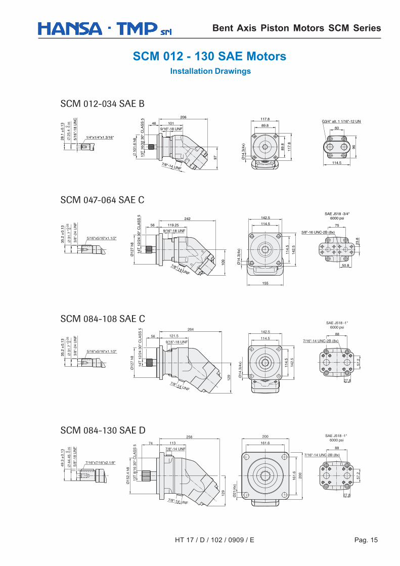
SCM 012 - 130 SAE Motors Installation Drawings
SCM 012-034 SAE B
SCM 047-064 SAE C
SCM 084-108 SAE C
SCM 084-130 SAE D
Pag. 16 HT 17 / D / 102 / 0909 / E
Bent Axis Piston Motors SCM Series
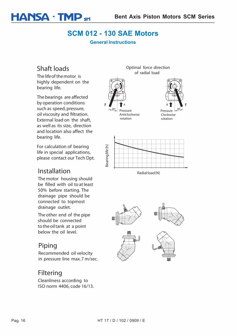
SCM 012 - 130 SAE MotorsGeneral Instructions
AF F20° 20°
B
Shaft loadsThe lifeof the motor ishighly dependent on thebearing life.
The bearings are affectedby operation conditionssuch as speed, pressure,oil viscosity and filtration.External load on the shaft,as well as its size, directionand location also affect thebearing life.
For calculation of bearinglife in special applications,please contact our Tech Dpt.
InstallationThe motor housing shouldbe filled with oil to at least50% before starting. Thedrainage pipe should beconnected to topmostdrainage outlet.
The other end of the pipeshould be connectedto the oil tank at a pointbelow the oil level.
PipingRecommended oil velocityin pressure line max.7 m/sec.
FilteringCleanliness according toISO norm 4406, code 16/13.
Radial load(N)
Bear
ing
life
(h)
PressureClockwiserotation
PressureAnticlockwiserotation
Optimal force directionof radial load
HT 17 / D / 102 / 0909 / E Pag. 17
Bent Axis Piston Motors SCM Series
SCM 012 - 130 SAE MotorsGeneral Instructions
Temperatures/Housing coolingExcessive system temperature reduces the life of the shaftseal and can lower the oil viscosity below the recommendedlevel. A system temperature of 60 °C anda drain flowtemperature of 90 °C must not be exceeded.Cooling/flushing of themotor housing can be needed tokeep the drain flow temperature at an acceptable level.
Suggested flow:Motor SCM Flushing l/min Cont. RPM 012-034 2-8 ≥ 2800 047-064 4-10 ≥ 2500 084-130 6-12 ≥ 2200
Hydraulic fluidsHighperformanceoilsmeetingISO specifications– suchasHM, DIN 51524-2HLP, or better– mustbe used.
A min.viscosity of 10 cSt is required to keep thelubrication at a safe level.
The ideal viscosity is 20 - 40 cSt.
Useful formulaes
Required flow rate Q = litres ⁄min.
Speed n = RPM
Torque M = Nm
Power P = kW
D = displacement, cm 3⁄revolution
n = speed, revolution ⁄min
P = power, kW
Q = flow rate, litres ⁄min
ηv = volumetric efficiency
ηhm = hydraulic-mechanical efficiency
ηt = overall efficiency = ηv x ηhm
M = torque, Nm
Δp = pressure difference between the hydraulic motor inlet and outlet, MPaMPa
D x n1000 x ηv
Q x 1000 x ηv
D
D x Δp x ηhm
6.3
Q x Δp x ηt
60
Q
Qflush
Qflush
Qflush
Housing flushing can be builtup with the help of a flushingvalve or taken directly from thereturn line.When the returnpressure is too low this iscompensated for by a counterpressure valve.The tank line is connected to thehighest point as in the figure.
Simplified circuits
Flus
hing
val
ve
Coun
ter
pres
sure
valv
e
Counterpressurevalve
Pag. 18 HT 17 / D / 102 / 0909 / E
Bent Axis Piston Motors SCM Series
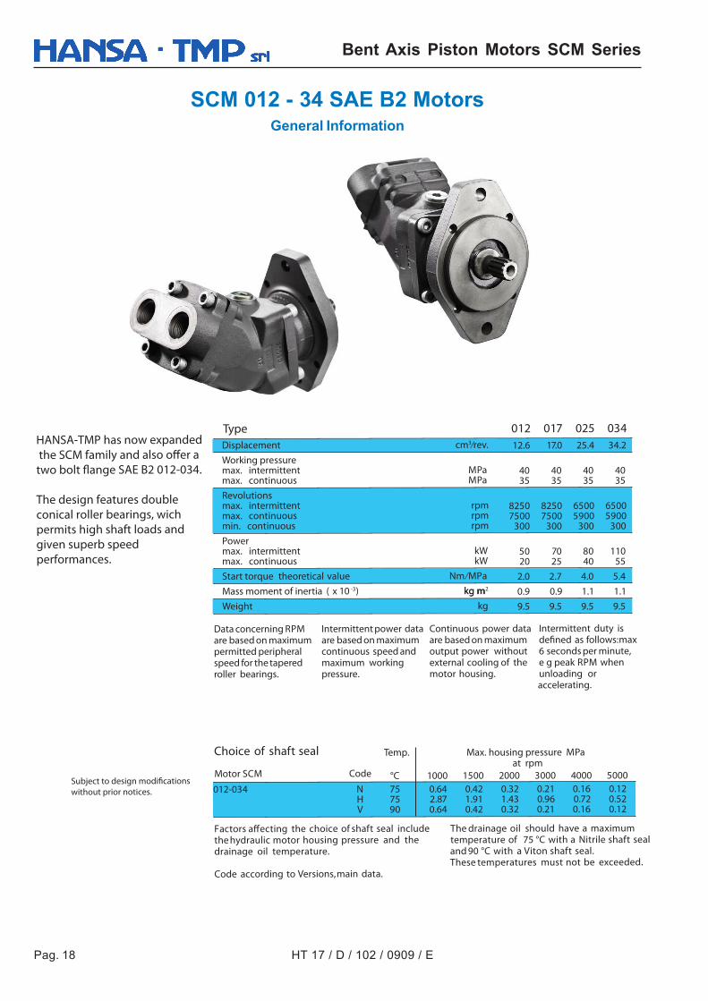
SCM 012 - 34 SAE B2 MotorsGeneral Information
012 017 025 03412.6 17.0 25.4 34.2
40 40 40 40 35 35 35 35
8250 8250 6500 6500 7500 7500 5900 5900 300 300 300 300
50 70 80 110 20 25 40 55
2.0 2.7 4.0 5.4
0.9 0.9 1.1 1.1
9.5 9.5 9.5 9.5
°C 1000 1500 2000 3000 4000 5000012-034 N 75 0.64 0.42 0.32 0.21 0.16 0.12
H 75 2.87 1.91 1.43 0.96 0.72 0.52 V 90 0.64 0.42 0.32 0.21 0.16 0.12
Displacement cm3⁄rev.
Working pressuremax. intermittent MPamax. continuous MPa
Revolutionsmax. intermittent rpmmax. continuous rpmmin. continuous rpm
Powermax. intermittent kWmax. continuous kW
Start torque theoretical value Nm ⁄MPa
Mass moment of inertia ( x 10 -3) kg mkg m2
Weight kg
Type
Data concerning RPMare based on maximumpermitted peripheralspeed for the taperedroller bearings.
Intermittent power dataare based on maximumcontinuous speed andmaximum workingpressure.
Continuous power dataare based on maximumoutput power withoutexternal cooling of themotor housing.
Intermittent duty isdefined as follows:max6 seconds per minute,e g peak RPM whenunloading oraccelerating.
HANSA-TMP has now expanded the SCM family and also offer a two bolt flange SAE B2 012-034.
The design features double conical roller bearings, wich permits high shaft loads and given superb speed performances.
Choice of shaft seal Temp. Max. housing pressure MPaat rpm
Motor SCM Code
Factors affecting the choice of shaft seal includethe hydraulic motor housing pressure and thedrainage oil temperature.
Code according to Versions,main data.
Subject to design modifications
without prior notices.
The drainage oil should have a maximumtemperature of 75 °C with a Nitrile shaft sealand 90 °C with a Viton shaft seal.These temperatures must not be exceeded.
HT 17 / D / 102 / 0909 / E Pag. 19
Bent Axis Piston Motors SCM Series
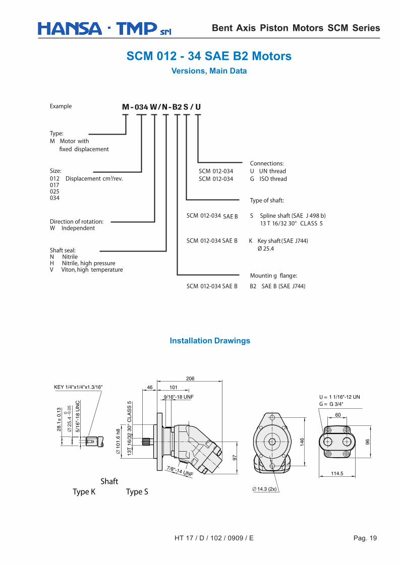
SCM 012 - 34 SAE B2 MotorsVersions, Main Data
SCM 012-034 SCM 012-034
SCM 012-034 SAE B13 T 16/32 30° CLASS 5
SCM 012-034 SAE BØ 25.4
SCM 012-034 SAE B B2 SAE B (SAE J744)
Example
Type:
M Motor withfixed displacement
Size:
012 Displacement cm3/rev.017025034
Direction of rotation:W Independent
Shaft seal:N NitrileH Nitrile, high pressureV Viton, high temperature
Connections:
U UN threadG ISO thread
Type of shaft:
S Spline shaft (SAE J 498 b)
K Key shaft(SAE J744)
Mountin g flange:
ShaftType K Type S
U =G =
Installation Drawings
Pag. 20 HT 17 / D / 102 / 0909 / E
Bent Axis Piston Motors SCM Series
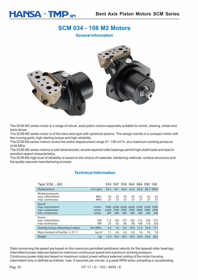
SCM 034 - 108 M2 MotorsGeneral Information
The SCM-M2 series motor is a range of robust axial piston motors expecially suitable for winch, slewing, wheel andtrack drives.The SCM-M2 series motor is of the bent-axis type with spherical pistons. The design results in a compact motor withfew moving parts, high starting torque and high reliability.The SCM-M2 series motors covers the entire displacement range 47- 108 cm3/n. at a maximum working pressureof 40 MPa.The SCM-M2 series motors is well dimensioned, double tapered roller bearings permit high shaft loads and lead toexcellent speed characteristics.The SCM-M2 high level of reliability is based on the choice of materials, hardening methods, surface structures andthe quality assured manufacturing process.
Data concerning the speed are based on the maximum permitted peripheral velocity for the tapered roller bearings.Intermittent power data are based on maximum continuous speed and maximum working pressure.Continuous power data are based on maximum output power without external cooling of the motor housing.Intermittent duty is defined as follows: max. 6 seconds per minute, e g peak RPM when unloading or accelerating.
Technical Information
034 047 056 064 084 090 108 34.2 47.1 56.0 63.5 83.6 90.7 108.0
42 42 42 42 42 42 4237 37 37 37 37 37 37
7000 6300 6300 6300 5200 5200 52006300 5700 5700 5700 4700 4700 4700
300 300 300 300 300 300 300
115 145 175 195 215 230 27555 65 80 90 100 110 130
5.4 7.5 8.9 10.0 13.3 14.4 17.1
1.1 2.6 2.6 2.6 7.4 7.4 7.4
11.0 18.3 18.3 18.3 26.0 26.0 26.0
Displacement cm3 ⁄ giroWorking pressuremax. intermittent MPamax. continuous MPaSpeedmax. intermittent n⁄min.max. continuous n⁄min.min. contiunuos n⁄min.Powermax intermittent kWmax continuous kWStarting torque (theoretical value) Nm⁄MPaMass moment of inertia ( x 10 -3) kg. m2
Weight kg
Type SCM......M2
HT 17 / D / 102 / 0909 / E Pag. 21
Bent Axis Piston Motors SCM Series
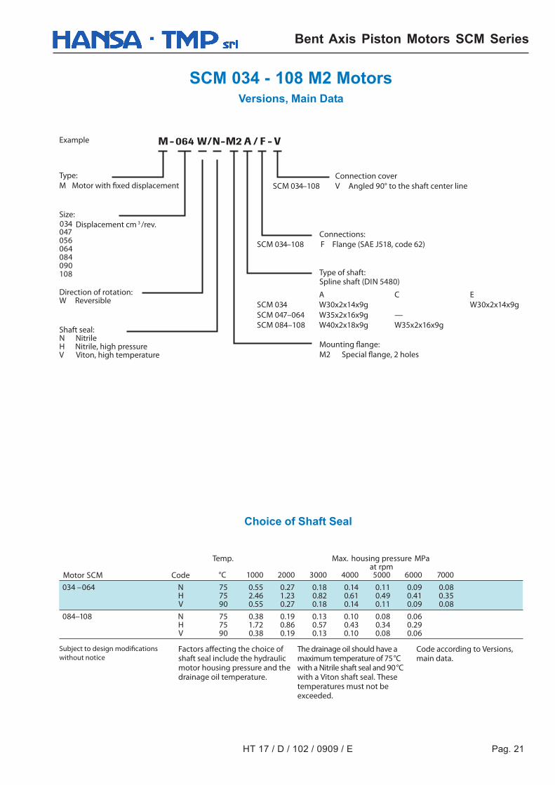
SCM 034 - 108 M2 MotorsVersions, Main Data
SCM 034–108
SCM 034–108 F
A C E
SCM 047–064 W35x2x16x9g —W30x2x14x9g
SCM 084–108 W40x2x18x9g W35x2x16x9g
°C 1000 2000 3000 4000 5000 6000 7000
034 –064 N 75 0.55 0.27 0.18 0.14 0.11 0.09 0.08 H 75 2.46 1.23 0.82 0.61 0.49 0.41 0.35V 90 0.55 0.27 0.18 0.14 0.11 0.09 0.08
084–108 N 75 0.38 0.19 0.13 0.10 0.08 0.06 H 75 1.72 0.86 0.57 0.43 0.34 0.29V 90 0.38 0.19 0.13 0.10 0.08 0.06
Example
Type:
M Motor with fixed displacement
Size:
047 Displacement cm 3 /rev.
056064084090108
Direction of rotation:W Reversible
Shaft seal:N NitrileH Nitrile, high pressureV Viton, high temperature
Connection cover
V Angled 90° to the shaft center line
Connections:
Flange (SAE J518, code 62)
Type of shaft:Spline shaft (DIN 5480)
Mounting flange:
M2 Special flange, 2 holes
Factors affecting the choice of shaft seal include the hydraulic motor housing pressure and the drainage oil temperature.
Subject to design modifications
without notice
Temp. Max. housing pressure MPa at rpm
Motor SCM Code
The drainage oil should have a maximum temperature of 75 °C with a Nitrile shaft seal and 90 °C with a Viton shaft seal. These temperatures must not be exceeded.
Code according to Versions, main data.
034
SCM 034 W30x2x14x9g
Choice of Shaft Seal

Pag. 22 HT 17 / D / 102 / 0909 / E
Bent Axis Piston Motors SCM Series
SCM 034 - 108 M2 Motors Installation Drawings
SCM 034 M2
SCM 084–108 M2
SCM 047–064 M2
O-ring included
O-ring included
O-ring included
HT 17 / D / 102 / 0909 / E Pag. 23
Bent Axis Piston Motors SCM Series
SCM 034 - 108 M2 MotorsGeneral Instructions
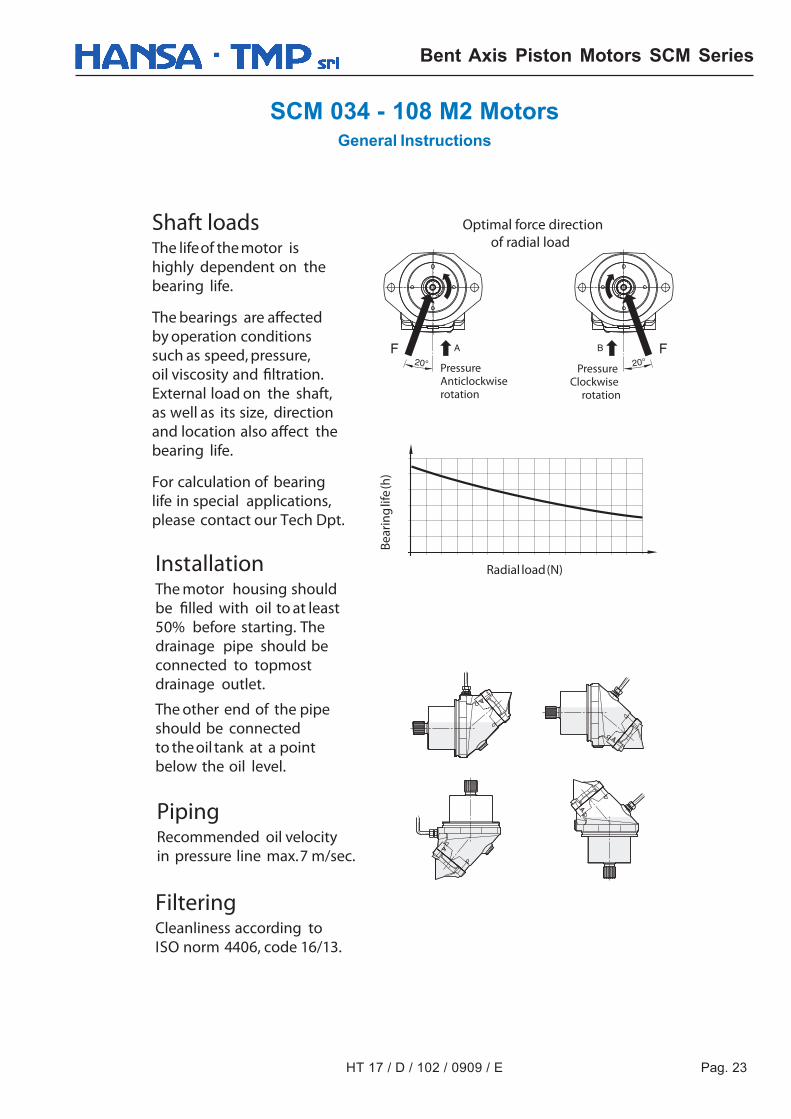
Shaft loadsThe lifeof the motor ishighly dependent on thebearing life.
The bearings are affectedby operation conditionssuch as speed, pressure,oil viscosity and filtration.External load on the shaft,as well as its size, directionand location also affect thebearing life.
For calculation of bearinglife in special applications,please contact our Tech Dpt.
InstallationThe motor housing shouldbe filled with oil to at least50% before starting. Thedrainage pipe should beconnected to topmostdrainage outlet.
The other end of the pipeshould be connectedto the oil tank at a pointbelow the oil level.
PipingRecommended oil velocityin pressure line max.7 m/sec.
FilteringCleanliness according toISO norm 4406, code 16/13.
Radial load(N)
Bear
ing
life
(h)
PressureClockwise
rotation
PressureAnticlockwiserotation
Optimal force directionof radial load
Pag. 24 HT 17 / D / 102 / 0909 / E
Bent Axis Piston Motors SCM Series
SCM 034 - 108 M2 MotorsGeneral Instructions
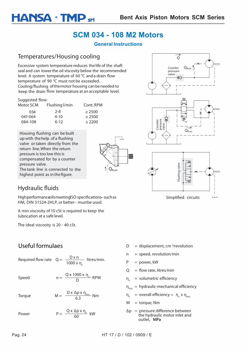
Temperatures/Housing coolingExcessive system temperature reduces the life of the shaftseal and can lower the oil viscosity below the recommendedlevel. A system temperature of 60 °C anda drain flowtemperature of 90 °C must not be exceeded.Cooling/flushing of themotor housing can be needed tokeep the drain flow temperature at an acceptable level.
Suggested flow:Motor SCM Flushing l/min Cont. RPM
034 ≥ 2500
Hydraulic fluidsHighperformanceoilsmeetingISO specifications– suchasHM, DIN 51524-2HLP, or better– mustbe used.
A min.viscosity of 10 cSt is required to keep thelubrication at a safe level.
The ideal viscosity is 20 - 40 cSt.
Useful formulaes
Required flow rate Q = litres ⁄min.
Speed n = RPM
Torque M = Nm
Power P = kW
D = displacement, cm 3⁄revolution
n = speed, revolution ⁄min
P = power, kW
Q = flow rate, litres ⁄min
ηv = volumetric efficiency
ηhm = hydraulic-mechanical efficiency
ηt = overall efficiency = ηv x ηhm
M = torque, Nm
Δp = pressure difference between the hydraulic motor inlet and outlet, MPaMPa
D x n1000 x ηv
Q x 1000 x ηv
D
D x Δp x ηhm
6.3
Q x Δp x ηt
60
Q
Qflush
Qflush
Housing flushing can be builtup with the help of a flushingvalve or taken directly from thereturn line.When the returnpressure is too low this iscompensated for by a counterpressure valve.The tank line is connected to thehighest point as in the figure.
Simplified circuits
Flus
hing
val
ve
Coun
ter
pres
sure
valv
e
Counterpressurevalve
Qflush
084-108 6-12 ≥ 2200 047-064 4-10 ≥ 2500
2-8
As HANSA-TMP has a very extensive range of products and some productshave a variety of applications, the information supplied may often onlyapply to specific situations. If the catalogue does not supply all theinformation required, please contact HANSA-TMP.
In order to provide a comprehensive reply to queries we may requirespecific data regarding the proposed application.
Whilst every reasonable endeavour has been made to ensure accuracythis publication cannot be considered to represent part of any contract,whether expressed or implied.
HANSA-TMP reserves the right to amend specifications at their discretion.