MOTOR POWERED CABLE REELS - pomazi.co.hu
38
MOTOR POWERED CABLE REELS
Transcript of MOTOR POWERED CABLE REELS - pomazi.co.hu

MOTOR POWEREDCABLE REELS

Contents PageReference installations 3-4General 5-7Determination of required cable cross section 8Examples of arrangements 9Questionnaire 10Determination of optimum drive configuration 11Type designation code compact drive-unit, principle circuit diagram 12Dimensional drawings motor reels with compact drive-units 13-17Principle circuit diagram torque motor 18Type designation code torque motor 19Dimensional drawings motor reels with torque motor 20-21Motor reels with converter drives 22Reel control 23Principle circuit drawings for motor reels with frequency drives 24Type designation code motor reels with converter drives 25Dimensional drawings motor reels with frequency controlled drives 26-27Cable types and sliprings 28Cable guides 29Feedpoint funnels 30Terminal cabinets 10kV and 20kV 31Cable grips 32Cable support rollers and anchor shackle 33
2
CONTENTS

Container crane Port BremerhavenFrequency controlled drive with tensileforce regulation incl. control.
Slipring body 10 KV with fiber optic cableand rotating coupler, 12 ports
Ø Reel drum: 7,4 mCable payout: 500 mCable: NTSCGEWÖU
6KV, 3 x 95 +2 x 50/3+18 LWL
Travel speed: 55 m/min.Mounting height: 20 m
Operating since 2002
Container crane Port DuisburgFrequency controlled drive with tensileforce regulation incl. control.
Slipring body 10 KV with fiber optic cableand rotating coupler, 6 ports
Ø Reel drum: 5,3 mCable payout: 500 mCable: NTSCGEWÖU
10KV, 3 x 95 +2 x 25/2+6 LWL
Travel speed: 120 m/min.Mounting height: 6 m
Operating since 2004
3
REFERENCE INSTALLATIONS

REFERENCE INSTALLATIONS
4
Container crane Port HamburgFrequency controlled drive with tensileforce regulation incl. control.
Slipring body 10 KV with fiber optic cableand rotating coupler, 18 ports
Ø Reel body: 7,2 mCable payout: 650 mCable: NTSCGEWÖU
10KV, 3 x 50 +2 x 25/2+18 LWL
Travel speed: 45 m/min.Mounting height: 22 m
Operating since 2004
Container crane MediterraneanPort Ashod/IsraelFrequency controlled drive with tensileforce regulation incl. control.
Slipring body 10 KV with fibre optic cableand rotating coupler, 6 ports
Ø Reel body: 6,4 mWinding width adjustableCable payout: 400 mCable: NTSCGEWÖU
6KV, 3 x 70 +2 x 25/+6 LWL
Travel speed: 45 m/min.Mounting height: 18,5 m
Operating since 2004
GENERAL
5
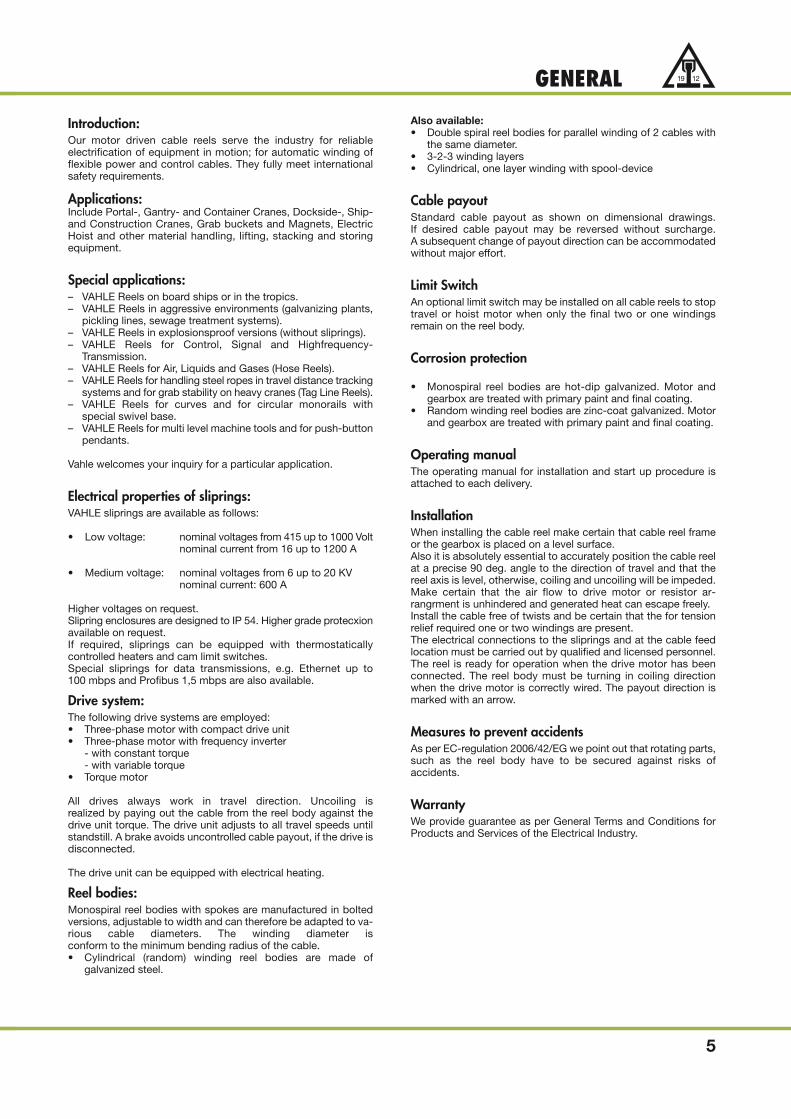
Introduction:Our motor driven cable reels serve the industry for reliable electrification of equipment in motion; for automatic winding offlexible power and control cables. They fully meet internationalsafety requirements.
Applications:Include Portal-, Gantry- and Container Cranes, Dockside-, Ship-and Construction Cranes, Grab buckets and Magnets, ElectricHoist and other material handling, lifting, stacking and storingequipment.
Special applications:– VAHLE Reels on board ships or in the tropics.– VAHLE Reels in aggressive environments (galvanizing plants,
pickling lines, sewage treatment systems).– VAHLE Reels in explosionsproof versions (without sliprings).– VAHLE Reels for Control, Signal and Highfrequency-
Transmission.– VAHLE Reels for Air, Liquids and Gases (Hose Reels).– VAHLE Reels for handling steel ropes in travel distance tracking
systems and for grab stability on heavy cranes (Tag Line Reels).– VAHLE Reels for curves and for circular monorails with
special swivel base.– VAHLE Reels for multi level machine tools and for push-button
pendants.
Vahle welcomes your inquiry for a particular application.
Electrical properties of sliprings:VAHLE sliprings are available as follows:
• Low voltage: nominal voltages from 415 up to 1000 Volt nominal current from 16 up to 1200 A
• Medium voltage: nominal voltages from 6 up to 20 KVnominal current: 600 A
Higher voltages on request.Slipring enclosures are designed to IP 54. Higher grade protecxionavailable on request.If required, sliprings can be equipped with thermostatically controlled heaters and cam limit switches.Special sliprings for data transmissions, e.g. Ethernet up to100 mbps and Profibus 1,5 mbps are also available.
Drive system:The following drive systems are employed:• Three-phase motor with compact drive unit• Three-phase motor with frequency inverter
- with constant torque- with variable torque
• Torque motor
All drives always work in travel direction. Uncoiling is realized by paying out the cable from the reel body against thedrive unit torque. The drive unit adjusts to all travel speeds untilstandstill. A brake avoids uncontrolled cable payout, if the drive isdisconnected.
The drive unit can be equipped with electrical heating.
Reel bodies:Monospiral reel bodies with spokes are manufactured in boltedversions, adjustable to width and can therefore be adapted to va-rious cable diameters. The winding diameter is conform to the minimum bending radius of the cable.• Cylindrical (random) winding reel bodies are made of
galvanized steel.
Also available:
• Double spiral reel bodies for parallel winding of 2 cables withthe same diameter.
• 3-2-3 winding layers• Cylindrical, one layer winding with spool-device
Cable payoutStandard cable payout as shown on dimensional drawings. If desired cable payout may be reversed without surcharge. A subsequent change of payout direction can be accommodatedwithout major effort.
Limit SwitchAn optional limit switch may be installed on all cable reels to stoptravel or hoist motor when only the final two or one windings remain on the reel body.
Corrosion protection
• Monospiral reel bodies are hot-dip galvanized. Motor and gearbox are treated with primary paint and final coating.
• Random winding reel bodies are zinc-coat galvanized. Motorand gearbox are treated with primary paint and final coating.
Operating manualThe operating manual for installation and start up procedure is attached to each delivery.
InstallationWhen installing the cable reel make certain that cable reel frameor the gearbox is placed on a level surface.Also it is absolutely essential to accurately position the cable reelat a precise 90 deg. angle to the direction of travel and that thereel axis is level, otherwise, coiling and uncoiling will be impeded.Make certain that the air flow to drive motor or resistor ar-rangrment is unhindered and generated heat can escape freely.Install the cable free of twists and be certain that the for tensionrelief required one or two windings are present.The electrical connections to the sliprings and at the cable feed location must be carried out by qualified and licensed personnel.The reel is ready for operation when the drive motor has beenconnected. The reel body must be turning in coiling directionwhen the drive motor is correctly wired. The payout direction ismarked with an arrow.
Measures to prevent accidentsAs per EC-regulation 2006/42/EG we point out that rotating parts,such as the reel body have to be secured against risks of accidents.
WarrantyWe provide guarantee as per General Terms and Conditions for Products and Services of the Electrical Industry.

Calculation of required cable cross section1. Determination of ampacity and cable cross section.
2. Control of voltage drop.
3. Selection of cable.
1. Determination of ampacity and cable cross section.The nominal currents (IN) of the individual motors are summarized with de-rating factors (fED, fT, f1, f2) to an equivalent continuous current (ID).
If necessary, the following calculation has to be carried out several times.
IN: Recommendation for nominal current
Estimated example for crane installations:
Sum up the nominal currents of the two motors with the strongest output and base load.
If only one power output is known:
P = Power [kW]
U = Voltage [V]
(cos � · �) = 0,8 estimated
fG = 1 individual power rating is known
fG = 0,9 only total power is known
fED: Reduction factors for intermittent duty as per table 1
fT: Reduction factors for elevated temperatures
Reduction factors for ambient temperatures above 30 °C as per table 2.
f1: Reduction factors for multilayer coiling
Reduction factors for ampacity depending on type of winding as per table 3. They are valid for permanently wound up cables.
Derating factors can be used if the cables are only temporarily wound up.
f2: Reduction factors for multicore cables
For multicore cables consider derating factors as per table 4 (only valid for cross-section up to 10 mm2)
2. Check of voltage-dropRough calculation to determine the voltage drop � U
L = total cable length [m]
IA = starting current [A]
Z = impedance [Ω/km]
for cos � = 0,6 from table 1
� U = recommendation � U < 5 %
INID = fED · fT · f1 · f2[A]
IN = P · 1000 · fG [A]√ 3 · U · (cos � · � )
6
GENERAL
IN = IN1 + IN2 + IG [A]
� U = √3 · L · IA ( Z ) [V]1000

IA: Calculation of start-up current
The order of the motor sizes does not depend on their power output , it is based on the level of the start-up current, i.e. a squirrel
cage motor with small power output, but with high start-up current will be placed in sequence before a slipring motor with higher po-
wer output.
Recommendation:
IA1 = 1. Motor with highest start-up current
IN2 = 2. Motor with highest nominal current
Advice:
Squirrel cage motor: X ≈ 6
Slipring motor: X ≈ 2
Frequency regulated motor: X ≈ 1,1
3. Selection of cables (larger type face, see page 6)
Select only suitable reeling cables as per regulation DIN / VDE 0298. Consider the smallest permissable bending radii (table 5).
Due to the required mechanical strength do not select cross sections of control cables lower than 1,5 mm2. We recommend to include spa-
re conductors for multicore control cables.
7
GENERAL
IA = IA1 + IN2 [A]
IA = X · IN [A]

Table 1: Continuous ampacity of cables type NSH . . . and NTS . . . for straight, open air lay down.Max. permissible operation temperature of the conductor 90° C.
Table 2: Multiplier for ambient temperature
Table 3: Multiplier for multilayer coilling
1,5
2,5
4
6
10
16
25
35
50
70
95
120
150
185
240
23
30
41
53
74
99
131
162
202
250
301
352
404
461
540
8,770
5,310
3,360
2,250
1,370
0,888
0,587
0,443
0,344
0,258
0,205
0,174
0,154
0,136
0,119
1,00 1,00 1,00 1,00
1,00 1,00 1,04 1,07
1,00 1,03 1,05 1,19
1,00 1,04 1,13 1,27
1,03 1,09 1,21 1,44
1,07 1,16 1,34 1,62
1,10 1,23 1,46 1,79
1,13 1,28 1,53 1,90
1,16 1,34 1,62 2,03
1,18 1,38 1,69 2,13
1,20 1,42 1,74 2,21
1,21 1,44 1,78 2,26
1,22 1,46 1,81 2,30
1,23 1,48 1,82 2,32
1,23 1,49 1,85 2,36
Wire size
[mm2]Continuous ampacity 30° C
[A] art 30 °CZ
[Ω / km]Multiplier for intermittent service
fED 60% 40% 25% 15%
25
1,05
Ambient temperature [°C]
Correction factor fT
30
1,00
35
0,95
40
0,89
45
0,84
50
0,77
55
0,71
60
0,63
65
0,55
1(1)
0,80
Number of full layerson reel
Correction factor f1
2
0,61
3
0,49
5
0,38
(1) also for spiral winding
The straight section between two bends in an S-shaped cable guide or guidance to another levelmust be at least 20-times the cable diameter.
Subject to technical advancement.
�20
·d
Table 4: Multiplier for multi-conductor cable,up to 10 mm2 wire size
5
0,75
7
0,65
10
0,55
14
0,50
19
0,45
24
0,40
40
0,35
61
0,30
Number of conductors
Correction factor f2
Table 5: Minimum bending radii
Type of cable
Flexible cables Overall diameterof cable in mm
above 8 - 12
3 x d 4 x d
5 x d
5 x d
4 x d
4 x d
5 x d
7,5 x d 7,5 x d 7,5 x d 15 x d
5 x d 6 x d 12 x d
above 12 - 20 above 20
4 x d 6 x d
10 x d
10 x d
5 x d
5 x d
fixed installation
fully flexible installation
for entry
for positiveguidance with reeling operation
for positive guidancewith rollers/sheaves
Nominal voltageup to 0,6 / 1 kV
Nominal voltageabove 0,6 / 1 kV
Remarks
If cable types can be used forseveral applications consultthe manufacturer.Suitabillity for this operationmust be guaranteed by special design features.
Cables PUR-HF 0,6/1 kV allow under positive guidance like reel operation up to 20 mm Ø a minimum permissible bending radius 6 x d.
8
CABLE SELECTION
9
TYPICAL APPLICATIONS
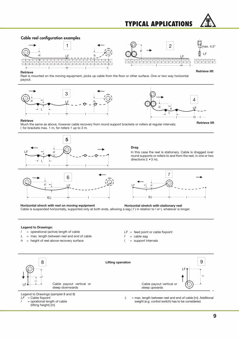
Retrieve
Reel is mounted on the moving equipment, picks up cable from the floor or other surface. One or two way horizontalpayout.
Retrieve
Much the same as above, however cable recovery from round support brackets or rollers at regular intervals;l
1for brackets max. 1 m, for rollers 1 up to 3 m.
Horizontal strech with reel on moving equipment
Cable is suspended horizontally, supported only at both ends, allowing a sag ( f ) in relation to l or L whatever is longer.
Legend to Drawings:
l = operational (active) length of cableL = max. length between reel and end of cableh = height of reel above recovery surface
LF = feed point or cable fixpointf = cable sagl
1= support intervals
Cable reel configuration examples
Drag
In this case the reel is stationary. Cable is dragged overround supports or rollers to and from the reel, in one or twodirections (l
1• 3 m).
Horizontal stretch with stationary reel
Lifting operation
Cable payout vertical orsteep downwards
Cable payout vertical orsteep upwards
Legend to Drawings (samplel 8 and 9)LF = Cable fixpointl = oprational length of cable
(lifting height) [m]
L = max. length between reel and end of cable [m]. Additionalweight (e.g. control switch) has to be considered.
LF
l
h h
l
1
LF
ll1
h f h
l
3
LF
ll1
h f
l
4
LF
l
l1
hf
l
5
LF
l(L) l
h f
6
LF
l(L)
hf
l
7
LF
8
l
L
LF
9
l
LFLF
max. 4,5°
l l
2
h
Retrieve lift
Retrieve lift

10
QUESTIONNAIRE
1. For what type of moving equipment is the reel?
(Dimensional drawings of equipment and application are extremely valuable)
1.1 Installation site indoor outdoor
1.2 Temperature conditions – °C + °C
1.3 Duty factor (time on) of full operating load % DF
1.4 Environmental conditions
2. Type of application (see page 6) example
2.1 Reel type random wrap monospiral wrap
3. Mounting height from center of reel to cable pickup surface m
4. Working travel of equipment in motion m
5. Cable Payout one-way two-way
6. Operational length of active cable l = m
(Midway feed-point cuts the length of cable needed in half)
6.1 For vertical lift (see page 4, example 8) l = m, L = m
6.2 Operated from a remote point to raise and lower cable at a controlled speed yes , no
6.2.1 Loads in addition to cable weight (pendant controls or receptacles) kg or Ibs
7. Choosen Cable (Number of copper conductors x wire size) x mm2 or #AWG
7.1 Weight of cable kg/m or Ibs/ft.
7.2 Diameter of cable mm or in.
8. Full operating load or maximum horsepower of equipment KW or HP
8.1 Nom. amperage (nominal current – IN) A
8.1.1 Start-up amperage (start-up current – IA) A
8.2 Voltage rating / frequency Hz
9. What percentage of the total installed ampacity will work simultaneously %
10. Number of phase collector rings required pcs.
(Our cable reel slipring assemblies always include one non-insulated ground)
11. How many cycles of the equipment per hour? cycles
12. Operating hours per day hours.
13. Speed of travel or lift m/min.
14. Shortest starting time sec.
15. Acceleration sec. m/sec.2
16. Details for reel drive motor
16.1 Voltage / frequency Hz
16.2 Duty cycle % DF
16.3 Is it possible to control reel drive motor from the host carrier yes no
17. Limit switch for travel or lift required yes no
Remarks:
V
V

HEspecially the duty cycle must be indicated. The
use of a reel that is calculated for intermittent
service can decrease the price by 30% and
more in comparison to a reel that is continuous-
ly operating. So, why waste money?
11
In the drive unit, represented in the sectional drawing above, theclutch is the main component which permits the constant torqueoutput.
A bronze crown gear (3), driven by a motor driven worm screw (2),is freely mounted on the reel shaft. Its surfaces are specially ma-chined.
The friction plates (4 and 5) are installed on either side of thecrown gear. They are made of steel and are fixed to the reel shaftwith a key.
The friction plates are also specially machined so while they areturning an oil film is generated between the crown gear and thefriction plates which transmits torque to the reel shaft.
In order to adjust the clutch to obtain the required output, the tor-que unit has an adjustable spring assembly which consists of therear friction plate (5), a series of springs (6), the spring holder pla-te (7) and the torque adjusting nut (8).
The rear friction plate is fixed to the reel shaft with a key, but canslide along the shaft axis. The torque adjusting nut is screwed on-to the reel shaft and pushes against the spring holder platethrough a series of steel balls.
The torque can be adjusted by placing the torque adjusting key (9)upside down into the torque unit. With the torque adjusting nut(8) held in place, the reel axle can be turned manually, thus increa-sing or decreasing the torque output of th clutch to the desired le-vel.
DETERMINATION OF OPTIMUM DRIVE CONFIGURATION
9 5 3 2 4 1
8 7 6
Advice for selection of the most suitable drive systemThe various characteristics of our different drives guarantee aneffective and cost saving solution for each application:
Intermittent dutyThe best solution for intermittent duty is in most cases the compact drive unit.
This system offers a very good price performance ratio for travelspeeds up tp approx. 60 m/min. and host carrier controlledintermittent duty service. The compact drive unit represents espe-cially for continuous operation of smaller sized equipment withmoderate speeds, the optimum solution.
Simple operation and high reliability are its well received attribu-tes.
Continuous operationMainly torque motors and frequency controlled drives are usedfor continuous operations.
• Torque motors: for smaller sized applications and lowertravel speeds
• Frequency
controlled drives: for sizable reels or high travel speeds
All essential parameters must be known to correctly design a mo-tor driven cable reel:
1. Type of application
2. Travel speed
3. Start-up acceleration
4. Total length of cable to be coiled
5. Type of cable (no. of poles + cross section)
6. Mounting height
7. Ambient temperature
8. Motor voltage / frequency
Please refer to our questionnaire on page 10.
Motor reels with compact drive unitsThe compact drive unit is coupled directly to the cable reel axle.This produces a very flat torque curve for coiling and uncoilingwhich in turns results in a substantially above average life cycle forthe cable.Torque fluctuations caused by coiling speed or slip are limited to5-10 % depending on the size of the drive unit.
This system offers an economical and easy to implement soluti-on for a great number of applications for cable and hose reels.It consists of a compact unit with integrated gearbox and clutchdriven by a squirrel cage motor.Hydraulic motors or compressed air motors can also be utilized.
The torque drive has a substantial advantage in that the torque iseasily adjustable. Therefore cable tension can be adjusted if siteconditions should require.

TYPE DESIGNATION CODE COMPACT DRIVE-UNITPRINCIPLE CIRCUIT DIAGRAM
12
Type code
LTC
LTC
400
motor sizenumber of poles of the motor
collector ring rating in Amps (100 % ED)
M = brass collector ring
number of collector rings
N = low voltage for horizontal payoutS = low voltage for vertical payoutH = high voltage for horizontal payout
monospiral wrap. Inside and outside diameter of reel in decimeter
motor reel with compact drive
Motor reel with compact drive-unit
random wrap - inside reel diameter in millimeter
15/30N
N4
4M
M50
90
A/8- 80
B/8-112
1M
3~PE
M1 Y1
WVU
1 2 3x1
K11
2
3
4
5
6
13
14
2 4 6
14
131 3 5 21
22
nominal voltage400 V / 50 Hz
L1L2L3PE
Q1
control voltage230 V / 50Hz
L10 1
2
6
7
13
14
A1
A2N10
13
14
x2:2
x2:1
K1
K2
Q1
x1
x1
F10
on/offby customertime-lag
for S3 operation
Motor
Release tocontrol circuitby others
VAHLE reel control with compact drive

REEL DIMENSIONAL DRAWINGSwith compact drive
13
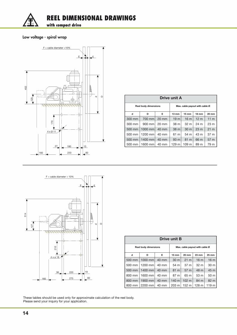
Low voltage - spiral wrap
Drive unit A
Reel body dimensions Max. cable payout with cable Ø
d D B 15 mm 20 mm 25 mm 30 mm
300 mm 600 mm 100 mm 34 m 24 m 18 m -
300 mm 600 mm 150 mm 50 m 41 m 24 m -
300 mm 600 mm 200 mm 67 m 53 m 33 m -
400 mm 800 mm 100 mm 43 m 30 m 23 m 24 m
400 mm 800 mm 150 mm 65 m 52 m 39 m 32 m
400 mm 800 mm 200 mm 86 m 67 m 55 m 49 m
These tables should be used only for approximate calculation of the reel body.Please send your inquiry for your application.
Drive unit B
Reel body dimensions Max. cable payout with cable Ø
d D B 15 mm 20 mm 25 mm 30 mm
300 mm 600 mm 100 mm 34 m 24 m 18 m -
300 mm 600 mm 150 mm 50 m 41 m 24 m -
300 mm 600 mm 200 mm 67 m 53 m 33 m -
400 mm 800 mm 100 mm 43 m 30 m 23 m 24 m
400 mm 800 mm 150 mm 65 m 52 m 39 m 32 m
400 mm 800 mm 200 mm 86 m 67 m 55 m 49 m
4 x Ø 11
200
125
452
Ø d
170
B
18027 13
220 63
Ø D
4 x Ø 18
Ø D
Ø d
210
250
22036 19
63.5
127
514
B
275
Low voltage - spiral wrap
Reel body dimensions Max. cable payout with cable Ø
d D E 13 mm 15 mm 18 mm 20 mm
300 mm 700 mm 20 mm 19 m 16 m 12 m 11 m
300 mm 900 mm 20 mm 38 m 32 m 24 m 23 m
500 mm 1000 mm 40 mm 38 m 30 m 23 m 21 m
500 mm 1200 mm 40 mm 61 m 54 m 43 m 37 m
500 mm 1400 mm 40 mm 93 m 81 m 66 m 57 m
500 mm 1600 mm 40 mm 129 m 109 m 89 m 79 m
Drive unit B
Reel body dimensions Max. cable payout with cable Ø
d D E 15 mm 20 mm 23 mm 25 mm
500 mm 1000 mm 40 mm 30 m 21 m 16 m 16 m
500 mm 1200 mm 40 mm 54 m 37 m 32 m 30 m
500 mm 1400 mm 40 mm 81 m 57 m 48 m 45 m
800 mm 1600 mm 40 mm 87 m 65 m 53 m 50 m
800 mm 1900 mm 40 mm 140 m 102 m 84 m 82 m
800 mm 2200 mm 40 mm 203 m 152 m 128 m 119 m
14
REEL DIMENSIONAL DRAWINGSwith compact drive
These tables should be used only for approximate calculation of the reel body.Please send your inquiry for your application.
d D
F = cable diameter +10%
170
125
452
13
60
180
220
27
160
4 x Ø 11
EE
d D
F = cable diameter + 10%
514
127
220 1936
275 60
4 x ø 18
210
160
E E
Drive unit A
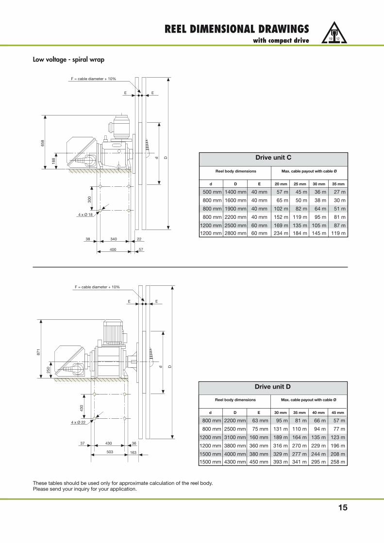
Low voltage - spiral wrap
Drive unit C
Reel body dimensions Max. cable payout with cable Ø
d D E 20 mm 25 mm 30 mm 35 mm
500 mm 1400 mm 40 mm 57 m 45 m 36 m 27 m
800 mm 1600 mm 40 mm 65 m 50 m 38 m 30 m
800 mm 1900 mm 40 mm 102 m 82 m 64 m 51 m
800 mm 2200 mm 40 mm 152 m 119 m 95 m 81 m
1200 mm 2500 mm 60 mm 169 m 135 m 105 m 87 m
1200 mm 2800 mm 60 mm 234 m 184 m 145 m 119 m
Reel body dimensions Max. cable payout with cable Ø
d D E 30 mm 35 mm 40 mm 45 mm
800 mm 2200 mm 63 mm 95 m 81 m 66 m 57 m
800 mm 2500 mm 75 mm 131 m 110 m 94 m 77 m
1200 mm 3100 mm 160 mm 189 m 164 m 135 m 123 m
1200 mm 3800 mm 360 mm 316 m 270 m 229 m 196 m
1500 mm 4000 mm 380 mm 329 m 277 m 244 m 208 m
1500 mm 4300 mm 450 mm 393 m 341 m 295 m 258 m
15
REEL DIMENSIONAL DRAWINGSwith compact drive
These tables should be used only for approximate calculation of the reel body.Please send your inquiry for your application.
F = cable diameter + 10%
4 x Ø 18
d D
300
188
658
EE
38 340 22
400 57
250
F = cable diameter + 10%
d D
871
EE
4 x Ø 22
37 430 36
503 163
430
Drive unit D
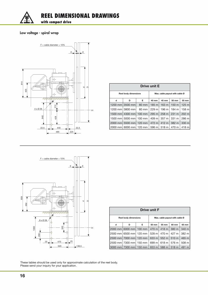
Low voltage - spiral wrap
Reel body dimensions Max. cable payout with cable Ø
d D E 40 mm 45 mm 50 mm 55 mm
1200 mm 3500 mm 80 mm 185 m 163 m 150 m 125 m
1200 mm 3800 mm 80 mm 229 m 196 m 184 m 158 m
1500 mm 4300 mm 100 mm 295 m 258 m 231 m 202 m
1500 mm 5000 mm 100 mm 409 m 357 m 331 m 286 m
2000 mm 5500 mm 120 mm 472 m 412 m 382 m 330 m
2000 mm 6000 mm 120 mm 596 m 518 m 470 m 418 m
Reel body dimensions Max. cable payout with cable Ø
d D E 50 mm 55 mm 60 mm 65 mm
2000 mm 6000 mm 100 mm 470 m 418 m 380 m 340 m
2500 mm 6500 mm 120 mm 528 m 470 m 427 m 382 m
2500 mm 7000 mm 120 mm 633 m 552 m 510 m 465 m
2500 mm 7300 mm 150 mm 699 m 618 m 576 m 508 m
3000 mm 7300 mm 150 mm 653 m 588 m 518 m 491 m
16
REEL DIMENSIONAL DRAWINGSwith compact drive
These tables should be used only for approximate calculation of the reel body.Please send your inquiry for your application.
d D
F = cable diameter + 10%
4 x Ø 26
640
814
22,5 440 22,5
485 225
212
428
cc
405
E E
d D
F = cable diameter + 10%
8 x Ø 28
1060
659
25 470 25
520 136,5
352
cc500
200
E E
Drive unit E
Drive unit F

Medium voltage
Reel body dimensions Max. cable payout with cable Ø
d D E 41 mm 44 mm 47 mm 53 mm
1200 mm 3500 mm 80 mm 187 m 172 m 156 m -
1200 mm 3800 mm 80 mm 220 m 205 m 189 m -
1500 mm 4300 mm 100 mm 285 m 255 m 237 m 211 m
1500 mm 5000 mm 100 mm 399 m 368 m 350 m 311 m
2000 mm 5500 mm 120 mm 461 m 425 m 404 m 358 m
2000 mm 6000 mm 120 mm 566 m 530 m 492 m 428 m
Reel body dimensions Max. cable payout with cable Ø
d D E 48 mm 50 mm 56 mm 60 mm
2000 mm 6000 mm 100 mm 479 m 470 m 403 m 380 m
2500 mm 6500 mm 120 mm 539 m 528 m 453 m 427 m
2500 mm 7000 mm 120 mm 642 m 633 m 557 m 510 m
2500 mm 7300 mm 150 mm 708 m 699 m 601 m 576 m
3000 mm 7300 mm 150 mm 664 m 653 m 569 m 518 m
17
REEL DIMENSIONAL DRAWINGSwith compact drive
These tables should be used only for approximate calculation of the reel body.Please send your inquiry for your application.
E E
F = cable diameter + 10%
680,5911201
525
409
d D
306,
548
3,5
150 260 180
830
1370
136,5
10 x ø 18
Dd
E
F = cable diameter + 10%
E
372
552
1000231,5 751,5
230 260 130
146,5
1400
450
450
960
10 x ø 23
260 260 260
Drive unit G
Drive unit H

18
MOTOR REELSwith torque motor
Motor reels with torque motorOur torque motors are especially designed for reel operation and have therefore an extremely flat torque curve. Usable rpm is 400 rpm which is considerably higher than for standard commercial torque motors.
Version• Motors with constant torque• Continuous operation 100% DC• Electromagnetic brake• Protection code IP 55• Ambient temperature up to 40 °C (standard) - Special versions for higher temperatures on request
Application• Continuous operation 100% DC• random wrap• monospiral wrap• Horizontal and vertical payout
Principle circuit diagram
1M
3~PE
M1 Y1
A1
A2
WVU
1 2 3 4 5x1
K11
2
3
4
5
6
13
14
2 4 6
14
131 3 5 21
22
nominal voltage400 V / 50 Hz
L1L2L3PE
Q1
-+~~
control voltage230 V / 50Hz
L10 1
2
6
7
13
14
A1
A2N10
13
14
x2:2
x2:1
K1
K2
Q1
x1
x1
F10
on/offby customertime-lag
for S3 operation
Motor
Release tocontrol circuitby others

19
TYPE DESIGNATION CODEMotor reels with torque motor
Type code
random wrap - inside reel diameter in millimeter
LTD
LTD
500
15/34
S
N
7 M 60
4 M 60
D 2
D 3
gearbox size
collector ring rating in Amps
M = brass collector ring
number of collector rings
N = low voltage for horizontal payoutS = low voltage for vertical payoutH = high voltage for horizontal payout
outside diameter of spool in decimeters
monospiral wrap
inside diameter of reel in decimeter
motor reel with torque motor
M 02
M 07
motor size

20
REEL DIMENSIONAL DRAWINGSwith torque motor
Low voltage - random wrap
120
F
Ø d
Ø D
190
120
4 x Ø 10 90 72
220
Reel body dimensions Max. cable payout with cable Ø
d D b 15 mm 20 mm 25 mm 30 mm
300 mm 600 mm 100 mm 34 m 24 m 18 m -
300 mm 600 mm 150 mm 50 m 41 m 24 m -
300 mm 600 mm 200 mm 67 m 53 m 33 m -
400 mm 800 mm 100 mm 43 m 30 m 23 m 24 m
400 mm 800 mm 150 mm 65 m 52 m 39 m 32 m
400 mm 800 mm 200 mm 86 m 67 m 55 m 49 m
E E
F = cable diameter + 10%
d
140
D
105
250
55
1504 x ø12
66
105
55
Reel body dimensions Max. cable payout with cable Ø
d D E 15 mm 20 mm 25 mm 30 mm
300 mm 700 mm 20 mm 16 m 11 m 8 m -
300 mm 900 mm 20 mm 32 m 23 m 17 m -
500 mm 1000 mm 40 mm 30 m 21 m 17 m 12 m
500 mm 1200 mm 40 mm 54 m 37 m 30 m 21 m
500 mm 1400 mm 40 mm 81 m 57 m 46 m 37 m
500 mm 1600 mm 40 mm 109 m 80 m 64 m 50 m
These tables should be used only for approximate calculation of the reel body.Please send your inquiry for your application.
Gearbox D2
Gearbox D3
Low voltage - monospiral wrap

21
REEL DIMENSIONAL DRAWINGSwith torque motor
Low voltage - monospiral wrap
d D
F = cable diameter + 10%
135
220 19
60275
4 x Ø 18
210
36
E E
Reel body dimensions Max. cable payout with cable Ø
d D E 25 mm 30 mm 35 mm 40 mm
500 mm 1000 mm 40 mm 17 m 12 m 10 m 7 m
500 mm 1200 mm 40 mm 30 m 21 m 19 m 13 m
500 mm 1400 mm 40 mm 46 m 37 m 27 m 24 m
800 mm 1600 mm 40 mm 50 m 38 m 30 m 27 m
800 mm 1900 mm 40 mm 82 m 64 m 51 m 42 m
800 mm 2200 mm 40 mm 119 m 95 m 82 m 66 m
800 mm 2500 mm 60 mm 163 m 131 m 110 m 95 m
E E
F = cable diameter + 10%
d
140
D
105
250
55
1504 x ø12
66
105
55
Reel body dimensions Max. cable payout with cable Ø
d D E 35 mm 40 mm 45 mm 50 mm
500 mm 1400 mm 40 mm 27 m 24 m - -
800 mm 1600 mm 40 mm 30 m 27 m 18 m 19 m
800 mm 1900 mm 40 mm 51 m 42 m 39 m 35 m
800 mm 2200 mm 40 mm 82 m 66 m 57 m 53 m
1200 mm 2500 mm 60 mm 87 m 76 m 64 m 59 m
1200 mm 2800 mm 60 mm 119 m 108 m 88 m 83 m
1200 mm 3100 mm 60 mm 164 m 135 m 123 m 110 m
These tables should be used only for approximate calculation of the reel body.Please send your inquiry for your application.
Gearbox D4
Gearbox D5

22
MOTOR REELSwith FI drive
• Horizontal cable payout with cable lengths up to 800 m
• Drive by start pinion gear units and torque motors
• Variable torque to protect the cable
• Cable control via limit switches in connection with guideroller assemblies.
Motor reels with frequency inverter drive can be supplied withconstant and variable torque.
With variable torque the motor will be controlled automaticallyby a potentiometer, depending on the cable payout length.
Therefore the tensile force on the cable is limited at any positionto the required minimum.

23
REEL CONTROLfor FI drives
Standard reel control units are available in four versions:
1. VAHLE compact control in compact housing
2. VAHLE compact control on mounting plate
3. VAHLE control in switch cabinet
4. VAHLE control on mounting plate
As an option the control unit is available in a stainless-steel housingor in a switch cabinet resp. on a mounting plate as per customersspecification. Examples for customer requests:
• Interface via Bus (e.g Profibus, CANopen, Interbus, ASI)• operating and / or signal station• Encoder signals via fiber optic• Special supply voltages and network configurations• Integrated with existing switch cabinet systems
VAHLE compact control
VAHLE control in switch panel
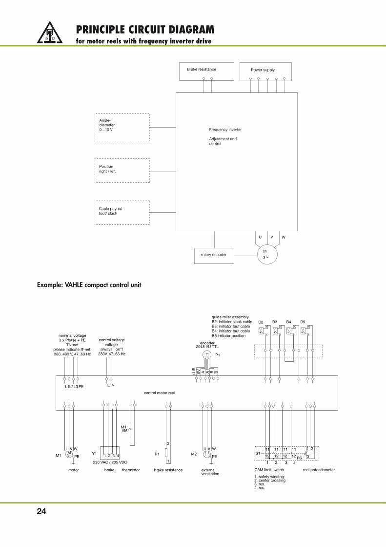
PRINCIPLE CIRCUIT DIAGRAMfor motor reels with frequency inverter drive
24
Brake resistance Power supply
Angle-diameter0...10 V
Positionright / left
Caple payouttout/ slack
rotary encoder
U V W
M
3~
Frequency inverter
Adjustment andcontrol
Example: VAHLE compact control unit
4321Y1
2.1.
11
12
11
12S1
L2L3 PEL1
1
3
2
R6M3
WVU
PEM1
1
2
R1WVU
PEM2
L N
1
2
1
2B3
1
2B4
1
2B5
P1
A+UB
0V BBA
nominal voltage3 x Phase + PE
TN-netplease indicate IT-net 380..480 V, 47..63 Hz
control voltagevoltage
always ''on''!230V, 47..63 Hz
guide roller assemblyB2: initiator slack cableB3: initiator taut cableB4: initiator taut cableB5 initiator position
B2
encoder2048 I/U TTL
motor
230 VAC / 205 VDC
brake thermistor
M1155°
brake resistance externalventilation
11 11
12 12
3. 4.
CAM limit switch reel potentiometer
1. safety winding2. center crossing3. res.4. res.
control motor reel

TYPE DESIGNATION CODEMotor reels with frecency inverter drive
25
Type code
monospiral wrap - inside diameter in millimeter
LTF
LTF
500
15/34
S
N
7 M 60
4 M 60
D 4
D 5
gearbox size
collector ring rating in Amps
M = brass collector ring
number of collector rings
N = low voltage for horizontal payoutS = low voltage for vertical payoutH = high voltage for horizontal payout
outside diameter of reel in decimeters
monospiral wrap
inside diameter of reel in decimeters
LTF = motor reel with frequency inverter
G
K
motor size
4
6
number of poles of the motor
FK
FP
FK = FI with variable torqueFP = FI with constant torque

26
REEL DIMENSIONAL DRAWINGSwith frequency inverter drive
Low voltageF = cable diameter + 10%
EE
188
d D
390
340
340
150
4 x Ø 22
150
Reel body dimensions Max. cable payout with cable Ø
d D E 25 mm 30 mm 35 mm 40 mm
500 mm 1400 mm 40 mm 27 m 24 m - -
800 mm 1600 mm 40 mm 30 m 27 m 18 m 19 m
800 mm 1900 mm 40 mm 51 m 42 m 39 m 35 m
800 mm 2200 mm 40 mm 82 m 66 m 57 m 53 m
1200 mm 2500 mm 60 mm 87 m 76 m 64 m 59 m
1200 mm 2800 mm 60 mm 119 m 108 m 88 m 83 m
1200 mm 3100 mm 60 mm 164 m 135 m 123 m 110 m
532,5911201
784
450
D
E
F = cable diameter + 10%
E
d
120 330
145
1230
350
290
680
8 x ø 18
330 330 120
Reel body dimensions Max. cable payout with cable Ø
d D E 40 mm 45 mm 50 mm 55 mm
1500 mm 4600 mm 100 mm 336 m 299 m 272 m 243 m
1500 mm 5000 mm 120 mm 409 m 357 m 331 m 286 m
2000 mm 4600 mm 100 mm 302 m 259 m 242 m 208 m
2000 mm 5000 mm 120 mm 375 m 332 m 301 m 266 m
2000 mm 5500 mm 120 mm 472 m 412 m 382 m 330 m
2000 mm 6000 mm 120 mm 578 m 518 m 470 m 418 m
2500 mm 6000 mm 120 mm 535 m 467 m 432 m 374 m
Medium voltage 6 kV
These tables should be used only for approximate calculation of the reel body.Please send your inquiry for your application.
Gearbox D5
Gearbox D6

27
REEL DIMENSIONAL DRAWINGSwith frequency inverter drive
Medium voltage 10 kV
Dd
E
F = cable diameter + 10%
E
620,5231,5
1000
487
372
250 275 150
305
685
1225
147
8 x Ø 22
305
275 275
Reel body dimensions Max. cable payout with cable Ø
d D E 45 mm 50 mm 55 mm 60 mm
1500 mm 4600 mm 100 mm 299 m 272 m 243 m 211 m
1500 mm 5000 mm 120 mm 357 m 331 m 286 m 269 m
2000 mm 4600 mm 100 mm 259 m 242 m 208 m 187 m
2000 mm 5000 mm 120 mm 332 m 301 m 266 m 246 m
2000 mm 5500 mm 120 mm 412 m 382 m 330 m 310 m
2000 mm 6000 mm 120 mm 518 m 470 m 418 m 380 m
2500 mm 6000 mm 120 mm 467 m 432 m 374 m 351 m
Dd
E
F = cable diameter + 10%
E
520
231,5
687
1450 785
190 295 130
1795
325
32512
90
12 x ø 22
295 295 295 295
Reel body dimensions Max. cable payout with cable Ø
d D E 45 mm 50 mm 55 mm 65 mm
1500 mm 5000 mm 120 mm 357 m 331 m 286 m 235 m
2000 mm 4600 mm 100 mm 259 m 242 m 208 m 179 m
2000 mm 5000 mm 120 mm 332 m 301 m 266 m 223 m
2000 mm 5500 mm 120 mm 412 m 382 m 330 m 271 m
2000 mm 6000 mm 120 mm 518 m 470 m 418 m 340 m
2500 mm 6000 mm 120 mm 467 m 432 m 374 m 307 m
2500 mm 7300 mm 150 mm 774 m 699 m 618 m 508 m
3000 mm 7300 mm 150 mm 713 m 653 m 588 m 491 m
Medium voltage 20 kV
These tables should be used only for approximate calculation of the reel body.Please send your inquiry for your application.
Gearbox D7
Gearbox D8

CABLE TYPES AND SLIPRING BODIES
28
Slipring bodies for:
• Low voltage up to 1 kV
• Medium voltage 1 kV - 25 kV
Cable types:
• Low voltage cables: Type NSHTÖU-J up to 1 kV• Low voltage cables: Type Trommelflex PUR-HF up to 1kV• Medium voltage cables from 1 - 25 kV with and without fiber optic• Special designs
Applications:
• Container crane applications• Stacker/Reclaimer• Discharging stations• Transfer carriers

ACCESSORIESCable guides
29
Guide roller without pendulum
Type max.cable Ø A B C D E F G H I K R ≈kg Order-No.
R 6 55 1140 860 145 - 360 125 430 598 92,5 M 16 600 85 924 994
R 9 75 1595 1200 180 - 606 164 670 900 111 M 20 900 150 924 995
R 12 83 2100 1660 210 - 560 500 740 1200 111 M 20 1200 250 924 996
Guide roller assemblymonospiral wrap
two-way payout
for up to 1000 Volt and
cable payout to 2 sides.
More than 1000 Volt rating requirer min. = 15 times cable OD
Guide roller with tension control
Type max.cable A B C D E F G H I K R ≈kg Order-No. Order-No.Ø c/w pos.- c/w pos.
switch switch
RZ 6 55 1700 930 185 123 360 125 430 598 92,5 M 16 600 95 926 576 924 742
RZ 9 75 2175 1240 220 140 606 164 670 900 111 M 20 900 160 925 073 925 002
RZ 12 83 2600 1710 220 140 560 500 740 1200 111 M 20 1200 260 926 573 925 003

30
ACCESSORIESFeedpoint funnels
Feedpoint funnelsfor applications up to 1000 Volt, two-way payout.
For medium travel speed and frequent traversing of midpoint.
Type ETZ 3 ETZ 4 ETZ 5 ETZ 7 ETZ 9 ETZ 12
Order-No. 921 380 921 390 921 400 921 410 921 720 926 651max.
34 50 6280 90
�90(1)
cable Ø �60(1) �60(1)
a 650 900 1220 1760 2070 2660b 530 700 900 1200 1475 1930c 106 146 208 208 216 60d/r 275 400 500 700 900 1200e 14 22 22f 200 125 150g 405 550 780 1080 1325 1780h 400 740 900 1100 1820 2220i 275 330k 120 210 180 350 1250 1660l 300 400 600 800 695 920m 270 410 480 750 960 1260n 60 80 120 120�kg 15 28 52 100 130 200
mid of cable
(1) allowed for applications of more than 1000 V.
40
220
18
100
center of cable

31
ACCESSORIESTerminal cabinets 10kV and 20kV
Terminal cabinet 10 kV- Order-No. 970 579Protection code IP 55Stainless steel housing
Terminal cabinet 20 kV- Order-No. 970 580Protection code IP 55Stainless steel housing
80
0
30
0
28
5
10
0
18
0
100
1
L2
L3
L1
195
2
130
ventilation
600
M12
55
3
150
300
M10
16
01
70
17
0
1
100
15
1: G 21/2´´ 45-52 mm
2: M8
3: M16 4,5-10 mm
85 mm
37
0
10,2
130
120
Lengths of cores:
PE: ~280 mm
L1: ~580 mm
L2: ~410 mm
L3: ~240 mm
makrolon cover
DangerHigh Voltage
HochspannungVorsicht
Lebnsgefahr
Housing: Stainless steel
Protection code: IP55
Supply voltage: 10kV
Frequency: 50/60 Hz
12
00
45
0
42
0
10
0
31
0
1001
260
2
L1
PE
L2
L3
130
M12
ventilation
90
3
M10
29
02
30
23
0
250
400
1
85
100
15
50
0
10,2
1: G 21/2´´ 45-52 mm
2: M8
3: M16 4,5-10 mm
210
500
190
Lengths of cores
PE: ~500 mm
L1: ~960 mm
L2: ~730 mm
L3: ~500 mm
Makrolon cover
Housing: Stainless steel Protection code: IP55
Supply voltage: 20 kV
Frequency: 50/60 Hz
DangerHigh Voltage
HochspannungVorsicht
Lebnsgefahr

32
ACCESSORIESCable grips
Cable grips, 1250 m long
Type Order-No. for cable-Ø Permissibletension(1) kg
VLZ 1 901 620 15-20 930VLZ 2 901 621 20-30 1165VLZ 3 901 622 30-40 1400VLZ 4 901 623 40-50 1630
for Ø 18 mm bolts
1250 ~ 250
(1) 3-times safety factor considered
Pressed with 2 grommets, also open at eye side grip ends without soldering point.
Cable grips
Type for cable-Ø Permissible length of wire mesh length of wire mesh Order-No.tension(1) kg measure L2 measure L1
VLZK 6 4 bis 7 60 100 275 900 391VLZK 9 7 bis 9 110 120 290 900 392VLZK 12 9 bis 12 130 135 340 900 393VLZK 15 12 bis 15 210 180 390 900 394VLZK 20 15 bis 20 260 220 450 900 395VLZK 25 20 bis 25 260 275 510 900 396VLZK 30 25 bis 30 400 350 610 900 397VLZK 40 30 bis 40 580 370 660 900 398
L1
L2

33
ACCESSORIESSupport rollers and anchor shackles
Cable support rollers
Rollers include bolts and washers
Type Order-No.
a b c
Weight~ kg
TR 80/110 B 200 924 450 110 – 130 2,25TR 80/300 B 200 924 460 300 – 320 3,25TR 80/500 B 200 924 470 500 – 520 4,50TR 80/110 B 200 H 924 480 110 80 130 3,50TR 80/300 B 200 H 924 490 300 250 320 5,15TR 80/500 B 200 H 924 500 500 400 520 6,90
w/obracket
c/wbracket
M 10 x 2,520
120
Ø 2
00Ø
80
105 a
bc
Ø 11R 8
660
ø 20
0
TypeOrder-No..
for cable-Ø r a d bWeight~ kg
Anchor shacklesfor up to 1000 Volt, for one or two-way payoutand low travelling speedsApplication: mainly used in connection with plug & socket serviceor when a vertical feeding connection from underneath the cable tray is impossible.
LS 1 921 420 –21,5 100 205 10 14 1,6LS 2 921 430 >21,5–28 130 225 10 14 2,5LS 3 921 440 >28 –36,5 170 265 12 17 3,5LS 4 921 450 >36,5–48 220 300 12 17 5,5
75°
r
d
b
a

NOTES
34

NOTES
35
PAUL VAHLE GMBH & CO. KG • Westicker Str. 52 • D 59174 KAMEN/GERMANY • TEL. (+49) 23 07/70 40Internet: www.vahle.de • E-Mail: [email protected] • FAX (+49) 23 07/70 44 44
Catalog No. 9b/E 2009
DQS - zertifiziert nach DIN EN ISO 9001:2000OHSAS 18001 (Reg.-Nr. 003140 QM OH)
MANAGEMENTSYSTEM
Products and Service Catalog No.
1 Open conductor systemsOpen conductor systems 1a
2 Insulated conductor systemsU 10 2aFABA 100 2bU 15 - U 25 - U 35 2cU 20 - U 30 - U 40 2d
3 Compact conductor systemsVKS 10 3aVKS - VKL 3b
4 Enclosed conductor systemsKBSL - KSL 4aKBH 4bMKLD - MKLF - MKLS 4cLSV - LSVG 4d
5 Contactless power systemContactless power system (CPS®) 5a
6 Data transmissionVAHLE Powercom® 6aSlotted Microwave Guide (SMG) 6b
7 Positioning systemsVAHLE APOS® 7a
8 Festoon systems and cablesFestoon systems for - tracks 8aFestoon systems for flat cables on - tracks 8bFestoon systems for round flat cables on - tracks 8cFestoon systems for - tracks 8dCables 8e
9 ReelsSpring operated cable reels 9aMotor powered cable reels 9b
10 OthersBattery charging systems 10aHeavy enclosed conductor systems 10bTender 10cContact wire 10d
Assemblies/CommissioningSpare parts/Maintenance service
0409
• P
rinte
d in
Ger
man
y •
1100
062/
00E
• D
S •
100
0 •
4/09

0909
• P
rinte
d in
Ger
man
y •
1100
062/
00E
• D
S •
100
0 •
9/09
Catalog No. 9b/E 2009
Products and Service Catalog No.
1 Copperhead conductor systemsPowerails 1a
2 Uni - pole insulated conductor systemsU 10 2aFABA 100 2bU 15 - U 25 - U 35 2cU 20 - U 30 - U 40 2d
3 Compact conductor systemsVKS 10 3aVKS - VKL 3b
4 Enclosed conductor systemsKBSL - KSL - KSLT 4aKBH 4bMKLD - MKLF - MKLS 4cLSV - LSVG 4d
5 Contactless Power System CPS®
CPS® Contactless Power System 5a
6 Communication systemsVAHLE Powercom® 6aSlotted Microwave Guide (SMG) 6b
7 Position encoding systemsVAHLE APOS 7a
8 Festoon systemsCable carriers for - tracks 8aCable carriers for flatform cables on - beams 8bCable carriers for round cables on - beams 8cCable carriers and accessories for - tracks 8dCables 8e
9 ReelsSpring operated cable reels 9aMotor powered cable reels 9b
10 OthersBattery charging systems 10aHeavy enclosed conductor systems 10bCable tenders 10cTrolley wire and accessories 10d
Installations/CommissioningSpare Parts/Maintenance ServiceMANAGEMENTSYSTEM
DQS certified in accordance with DIN EN ISO 9001:2000
OHSAS 18001 (Reg. no. 003140 QM OH)
VAHLE INC. • 1167 Brittmoore • Houston, TX 77043 • Phone 713/465-9796 • Fax 713/465-1851
Catalog No. 9b/E 2009
DQS - zertifiziert nach DIN EN ISO 9001:2000OHSAS 18001 (Reg.-Nr. 003140 QM OH)
MANAGEMENTSYSTEM
Products and Service Catalog No.
1 Open conductor systemsOpen conductor systems 1a
2 Insulated conductor systemsU 10 2aFABA 100 2bU 15 - U 25 - U 35 2cU 20 - U 30 - U 40 2d
3 Compact conductor systemsVKS 10 3aVKS - VKL 3b
4 Enclosed conductor systemsKBSL - KSL 4aKBH 4bMKLD - MKLF - MKLS 4cLSV - LSVG 4d
5 Contactless power systemContactless power system (CPS®) 5a
6 Data transmissionVAHLE Powercom® 6aSlotted Microwave Guide (SMG) 6b
7 Positioning systemsVAHLE APOS® 7a
8 Festoon systems and cablesFestoon systems for - tracks 8aFestoon systems for flat cables on - tracks 8bFestoon systems for round flat cables on - tracks 8cFestoon systems for - tracks 8dCables 8e
9 ReelsSpring operated cable reels 9aMotor powered cable reels 9b
10 OthersBattery charging systems 10aHeavy enclosed conductor systems 10bTender 10cContact wire 10d
Assemblies/CommissioningSpare parts/Maintenance service
0409
• P
rinte
d in
Ger
man
y •
1100
062/
00E
• D
S •
300
• 4
/09
POWERAIL LTD.WORKING FOR THE FUTURE WITH
Powerail Ltd. High Road, Finchley, London, N12 8PT,Phone 020 8446 0350/1246 • Fax 020 8446 7054
E-mail: [email protected]