
Manual - Cable Reels, 1500 Series Hazardous Loc.
20
1500 Series Power Reel Hazardous Location Manual XA-962005.7 Hazardous Location Cable Reel Manual 1500 Series Power Reel ™
Transcript of Manual - Cable Reels, 1500 Series Hazardous Loc.
1500 Series Power Reel Hazardous Location ManualXA-962005.7
Hazardous Location Cable Reel Manual 1500 Series Power Reel™www.conductix.us

2 1500 Series Power Reel Hazardous Location ManualXA-962005.7
TABLE OF CONTENTS
SECTION 1 - SAFETY 5Safety Information Responsibility 5
Safety Messages 5
Electrical Warnings 6
Operational Warnings 6
Maintenance Warnings 6
Electrical Rating 7
Labels & Markings 7
SECTION 2 - INSTALLATION 8Application Types 8
Stretch Applications 8Lift Applications 8Drag Applications 8Retrieve Applications 8
Mounting 9Standard Mounting 9Pivot Base Mounting 10
Roller Guide 10
Ratchet 11Ratchet Lock 11Operation with Ratchet 11Operation without Ratchet 11
Cable Installation 11
Spring Tension Adjustment 12
Power Connections 13
SECTION 3 - OPERATION 14SECTION 4 - MAINTENANCE 15Lubrication 15
Inspections 15
Slip Ring Replacement 15
Cable Replacement 15
Spring Motor Replacement 15
SECTION 5 - TROUBLESHOOTING 16SECTION 6 - REPLACEMENT PARTS 17
1500 Series Power Reel Hazardous Location Manual 3 XA-962005.7
CONDUCTIX INCORPORATEDThe technical data and images which appear in this manual are for informational purposes only. NO WARRANTIES, EXPRESS OR IMPLIED, INCLUDING WARRANTIES OF MERCHANTABILITY OR FITNESS FOR A PARTICULAR PURPOSE, ARE CREATED BY THE DESCRIPTIONS AND DEPICTIONS OF THE PRODUCTS SHOWN IN THIS MANUAL. Conductix-Wampfler makes no warranty (and assumes no liability) as to function of equipment or operation of systems built according to customer design or of the ability of any of its products to interface, operate, or function with any portions of customer systems not provided by Conductix-Wampfler.Seller agrees to repair or exchange the goods sold hereunder necessitated by reason of defective workmanship and material discovered and reported to Seller within one year after shipment of such goods to Buyer.Except where the nature of the defect is such that it is appropriate, in Seller’s judgment, to effect repairs on site, Seller’s obligation hereunder to remedy defects shall be limited to repairing or replacing (at Seller’s option) FOB point of original shipment by Seller, any part returned to Seller at the risk and cost of Buyer. Defective parts replaced by Seller shall become the property of Seller.Seller shall only be obligated to make such repair or replacement if the goods have been used by Buyer only in service recommended by Seller and altered only as authorized by Seller. Seller is not responsible for defects which arise from improper installation, neglect, or improper use or from normal wear and tear.Additionally, Seller’s obligation shall be limited by the manufacturer’s warranty (and is not further warranted by Seller) for all parts procured from others according to published data, specifications or performance information not designed by or for Seller.Seller further agrees to replace or at Seller’s option to provide a refund of the sales price of any goods that do not conform to applicable specifications or which differ from that agreed to be supplied which non-conformity is discovered and forthwith reported to Seller within thirty (30) days after shipment to the Buyer. Seller’s obligation to replace or refund the purchase price for non-conforming goods shall arise once Buyer returns such goods FOB point of original shipment by Seller at the risk and cost of Buyer. Goods replaced by Seller shall become the property of Seller.There is no guarantee or warranty as to anything made or sold by Seller, or any services performed, except as to title and freedom from encumbrances and, except as herein expressly stated and particularly, and without limiting the foregoing, there is no guarantee or warranty, express or implied, of merchantability or of fitness for any particular purpose or against claim of infringement or the like.Seller makes no warranty (and assumes no liability) as to function of equipment or operation of systems built to Buyer’s design or of the ability of any goods to interface, operate, or function with any portions of Buyer’s system not provided by Seller.Seller’s liability on any claim, whether in contract, tort (including negligence), or otherwise, for any loss or damage arising out of, connected with, or resulting from the manufacture, sale, delivery, resale, repair, replacement, or use of any products or services shall in no case exceed the price paid for the product or services or any part thereof which give rise to the claim. In no event shall Seller be liable for consequential, special, incidental, or other damages, nor shall Seller be liable in respect of personal injury or damage to property not the subject matter hereof unless attributable to gross misconduct of Seller, which shall mean an act or omission by Seller demonstrating reckless disregard of the foreseeable consequences thereof.Seller is not responsible for incorrect choice of models or where products are used in excess of their rated and recommended capacities and design functions or under abnormal conditions. Seller assumes no liability for loss of time, damage, or injuries to property or persons resulting from the use of Seller’s products. Buyer shall hold Seller harmless from all liability, claims, suits, and expenses in connection with loss or damage resulting from operation of products or utilization of services, respectively, of Seller and shall defend any suit or action which might arise there from in Buyer’s name - provided that Seller shall have the right to elect to defend any such suit or action for the account of Buyer. The foregoing shall be the exclusive remedies of the Buyer and all persons and entitles claiming through the Buyer.

4 1500 Series Power Reel Hazardous Location ManualXA-962005.7
CONDUCTIX-WAMPFLER FIELD SERVICE
Need Field Service for our products? We Can Handle It!
Ask us for a quote on expert system installations, inspections, preventative maintenance, and repairs/retrofits.
As the world’s largest single source manufacturer of mobile electrification products, Conductix-Wamplfer has the unique ability to offer a degree of service not found anywhere else. Conductix-Wampfler's team of highly qualified service technicians and engineers have years of experience servicing our complete line of products.
We can provide:• Annual service contracts• Installation• Commissioning• Installation supervision to ensure your installers avoid common mistakes.• Troubleshooting to get you up and running.• Pre-planned inspections to complement your preventive maintenance program.
Call 1.800.521.4888 for further details.
1500 Series Power Reel Hazardous Location Manual 5 XA-962005.7
SECTION 1 - SAFETY
Safety Information ResponsibilityAll owner, operator, and maintenance personnel must read and understand all manuals associated with this product before installation, operation, or maintenance.
The manual provides information on the recommended installation, operation, and maintenance of this product. Failure to read and follow the information provided could cause harm to yourself or others and/or cause product damage. No one should install, operate, or attempt maintenance of this product prior to familiarizing themselves with the information in this manual.
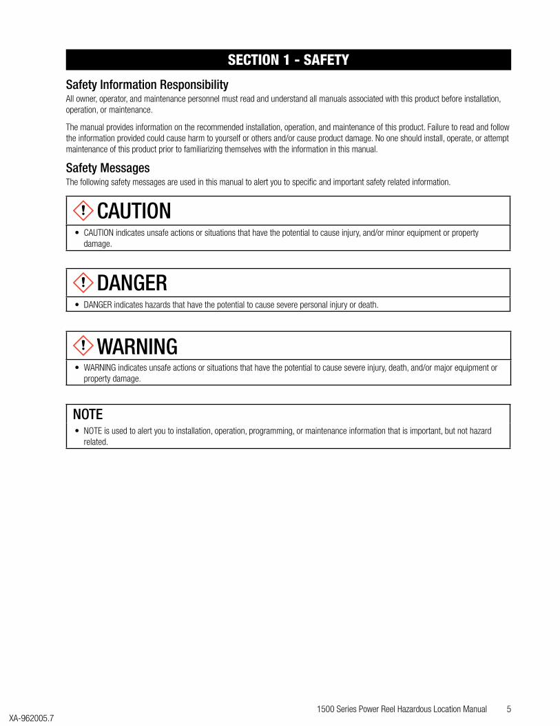
Safety MessagesThe following safety messages are used in this manual to alert you to specific and important safety related information.
CAUTION• CAUTION indicates unsafe actions or situations that have the potential to cause injury, and/or minor equipment or property
damage.
DANGER
• DANGER indicates hazards that have the potential to cause severe personal injury or death.
WARNING• WARNING indicates unsafe actions or situations that have the potential to cause severe injury, death, and/or major equipment or
property damage.
NOTE• NOTE is used to alert you to installation, operation, programming, or maintenance information that is important, but not hazard
related.
6 1500 Series Power Reel Hazardous Location ManualXA-962005.7
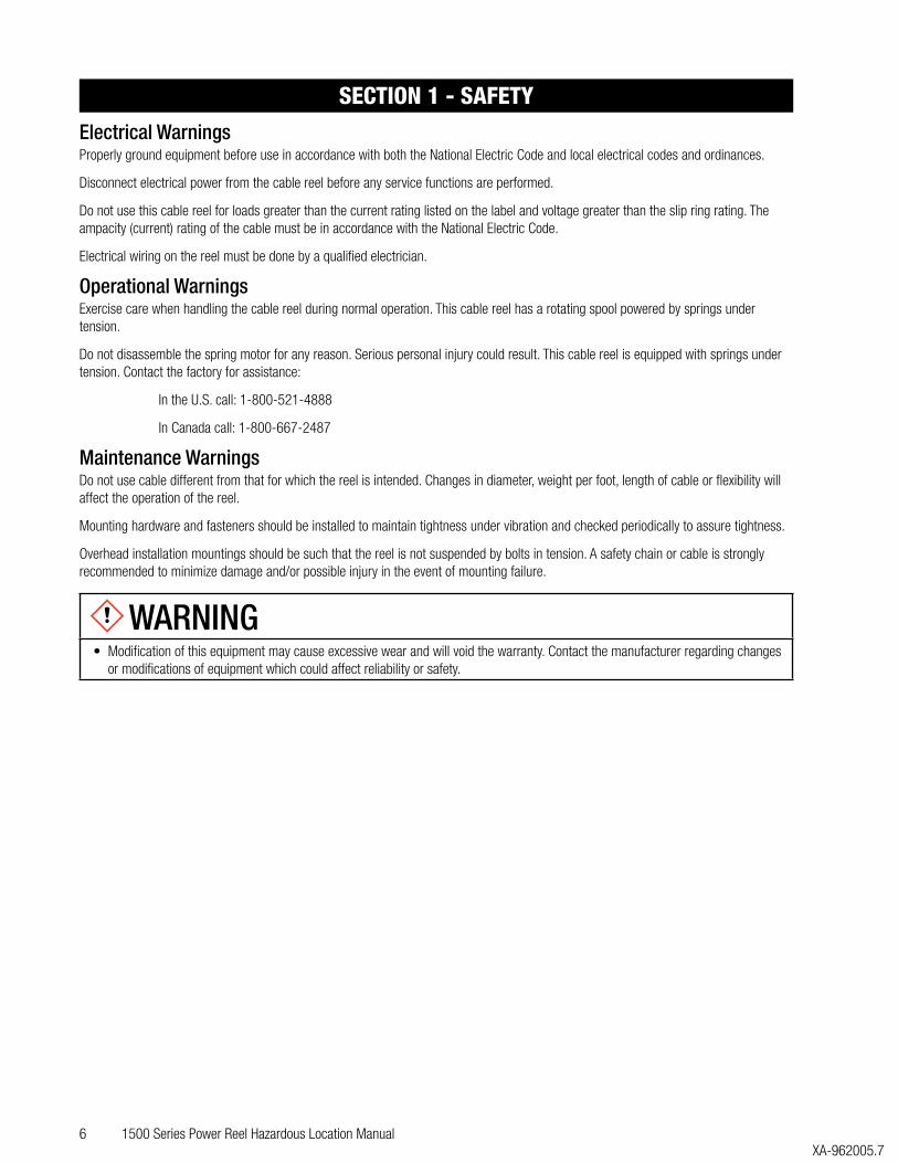
Electrical WarningsProperly ground equipment before use in accordance with both the National Electric Code and local electrical codes and ordinances.
Disconnect electrical power from the cable reel before any service functions are performed.
Do not use this cable reel for loads greater than the current rating listed on the label and voltage greater than the slip ring rating. The ampacity (current) rating of the cable must be in accordance with the National Electric Code.
Electrical wiring on the reel must be done by a qualified electrician.
Operational WarningsExercise care when handling the cable reel during normal operation. This cable reel has a rotating spool powered by springs under tension.
Do not disassemble the spring motor for any reason. Serious personal injury could result. This cable reel is equipped with springs under tension. Contact the factory for assistance:
In the U.S. call: 1-800-521-4888
In Canada call: 1-800-667-2487
Maintenance WarningsDo not use cable different from that for which the reel is intended. Changes in diameter, weight per foot, length of cable or flexibility will affect the operation of the reel.
Mounting hardware and fasteners should be installed to maintain tightness under vibration and checked periodically to assure tightness.
Overhead installation mountings should be such that the reel is not suspended by bolts in tension. A safety chain or cable is strongly recommended to minimize damage and/or possible injury in the event of mounting failure.
WARNING• Modification of this equipment may cause excessive wear and will void the warranty. Contact the manufacturer regarding changes
or modifications of equipment which could affect reliability or safety.
SECTION 1 - SAFETY
1500 Series Power Reel Hazardous Location Manual 7 XA-962005.7
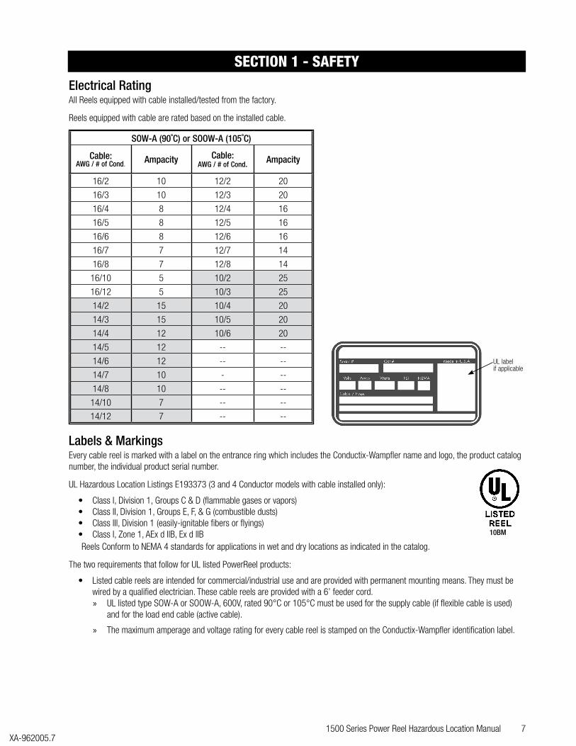
Electrical RatingAll Reels equipped with cable installed/tested from the factory.
Reels equipped with cable are rated based on the installed cable.
SOW-A (90˚C) or SOOW-A (105˚C)
Cable:AWG / # of Cond. Ampacity Cable:
AWG / # of Cond. Ampacity
16/2 10 12/2 20
16/3 10 12/3 20
16/4 8 12/4 16
16/5 8 12/5 16
16/6 8 12/6 16
16/7 7 12/7 14
16/8 7 12/8 14
16/10 5 10/2 25
16/12 5 10/3 25
14/2 15 10/4 20
14/3 15 10/5 20
14/4 12 10/6 20
14/5 12 -- --
14/6 12 -- --
14/7 10 - --
14/8 10 -- --
14/10 7 -- --
14/12 7 -- --
Labels & MarkingsEvery cable reel is marked with a label on the entrance ring which includes the Conductix-Wampfler name and logo, the product catalog number, the individual product serial number.
UL Hazardous Location Listings E193373 (3 and 4 Conductor models with cable installed only):
• Class I, Division 1, Groups C & D (flammable gases or vapors)• Class II, Division 1, Groups E, F, & G (combustible dusts)• Class III, Division 1 (easily-ignitable fibers or flyings)• Class I, Zone 1, AEx d llB, Ex d llBReels Conform to NEMA 4 standards for applications in wet and dry locations as indicated in the catalog.
The two requirements that follow for UL listed PowerReel products:
• Listed cable reels are intended for commercial/industrial use and are provided with permanent mounting means. They must be wired by a qualified electrician. These cable reels are provided with a 6’ feeder cord. » UL listed type SOW-A or SOOW-A, 600V, rated 90°C or 105°C must be used for the supply cable (if flexible cable is used)
and for the load end cable (active cable).
» The maximum amperage and voltage rating for every cable reel is stamped on the Conductix-Wampfler identification label.
UL labelif applicable
10BM
SECTION 1 - SAFETY
8 1500 Series Power Reel Hazardous Location ManualXA-962005.7
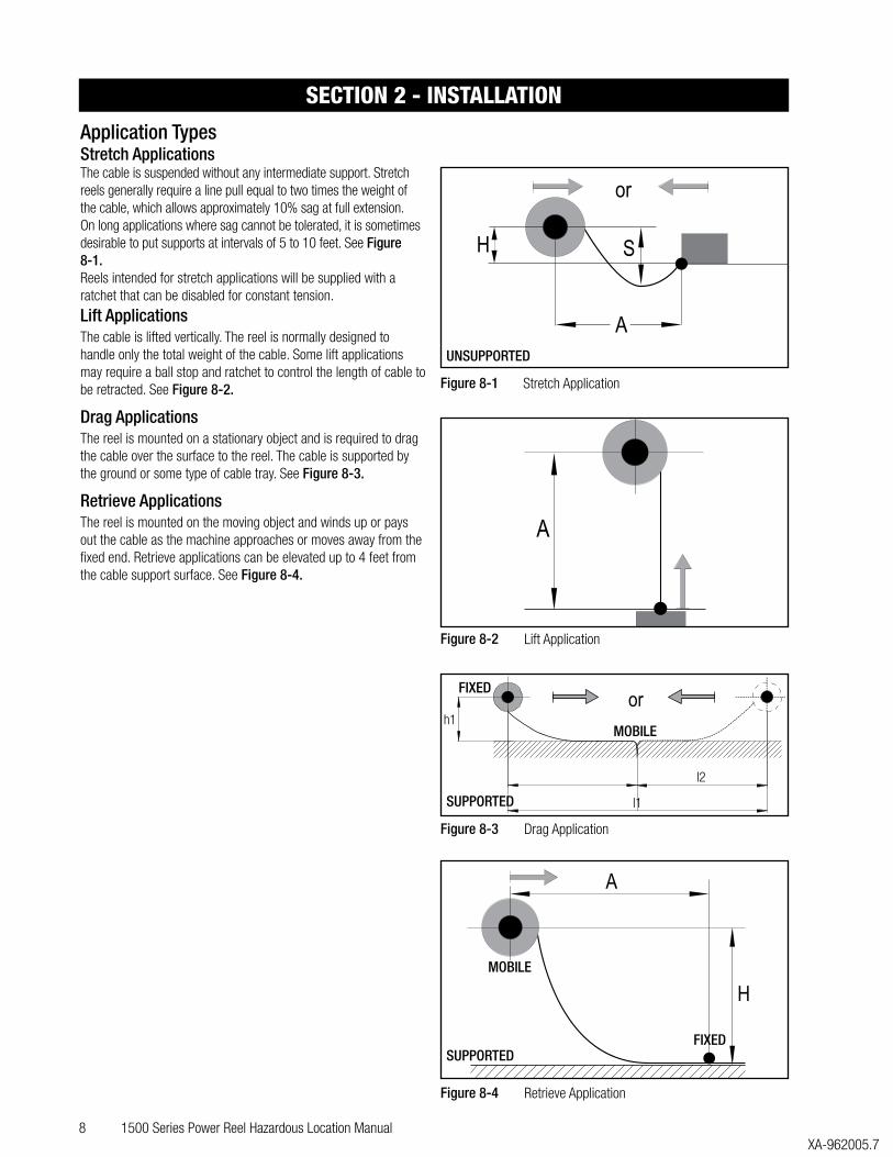
Application TypesStretch ApplicationsThe cable is suspended without any intermediate support. Stretch reels generally require a line pull equal to two times the weight of the cable, which allows approximately 10% sag at full extension. On long applications where sag cannot be tolerated, it is sometimes desirable to put supports at intervals of 5 to 10 feet. See Figure 8-1.Reels intended for stretch applications will be supplied with a ratchet that can be disabled for constant tension.
Lift ApplicationsThe cable is lifted vertically. The reel is normally designed to handle only the total weight of the cable. Some lift applications may require a ball stop and ratchet to control the length of cable to be retracted. See Figure 8-2.
Drag ApplicationsThe reel is mounted on a stationary object and is required to drag the cable over the surface to the reel. The cable is supported by the ground or some type of cable tray. See Figure 8-3.
Retrieve ApplicationsThe reel is mounted on the moving object and winds up or pays out the cable as the machine approaches or moves away from the fixed end. Retrieve applications can be elevated up to 4 feet from the cable support surface. See Figure 8-4.
SECTION 2 - INSTALLATION
A
SH
or
Figure 8-1 Stretch Application
A
Figure 8-2 Lift Application
h1
l2
l1
or
Figure 8-3 Drag Application
A
H
Figure 8-4 Retrieve Application
UNSUPPORTED
SUPPORTEDFIXED
MOBILE
FIXED
MOBILE
SUPPORTED
1500 Series Power Reel Hazardous Location Manual 9 XA-962005.7
MountingStandard MountingThe reel may be mounted by bolting the base to any flat surface which is structurally sound enough to support it and the forces of winding and unwinding the cable.
The spool drum must rotate on a level horizontal axis.
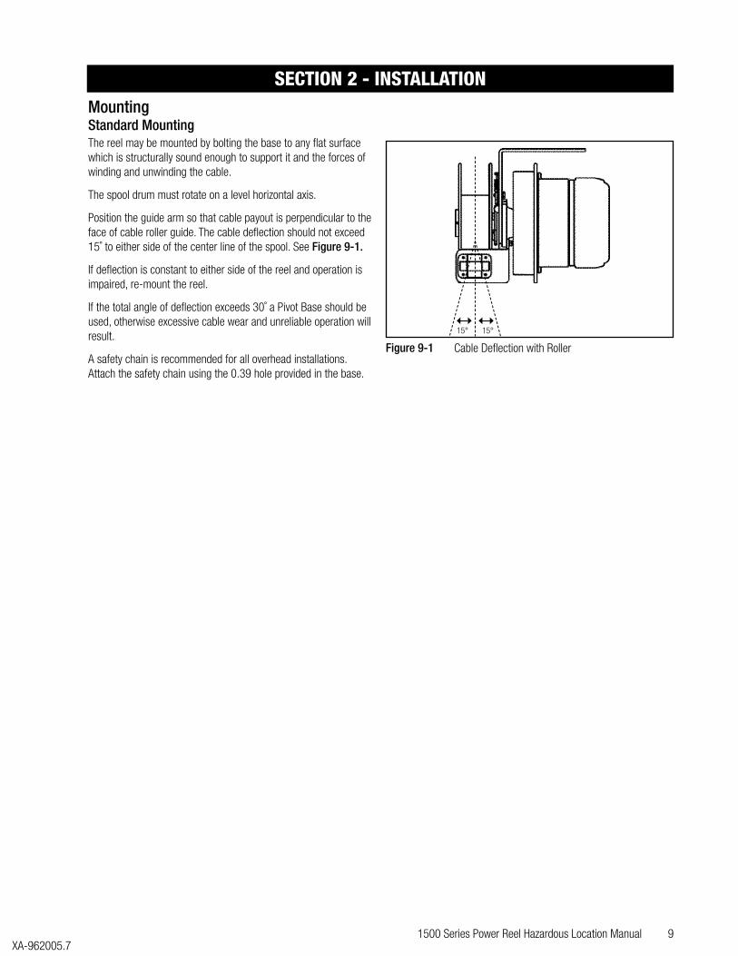
Position the guide arm so that cable payout is perpendicular to the face of cable roller guide. The cable deflection should not exceed 15˚ to either side of the center line of the spool. See Figure 9-1.
If deflection is constant to either side of the reel and operation is impaired, re-mount the reel.
If the total angle of deflection exceeds 30˚ a Pivot Base should be used, otherwise excessive cable wear and unreliable operation will result.
A safety chain is recommended for all overhead installations. Attach the safety chain using the 0.39 hole provided in the base.
SECTION 2 - INSTALLATION
15° 15°
Figure 9-1 Cable Deflection with Roller
10 1500 Series Power Reel Hazardous Location ManualXA-962005.7
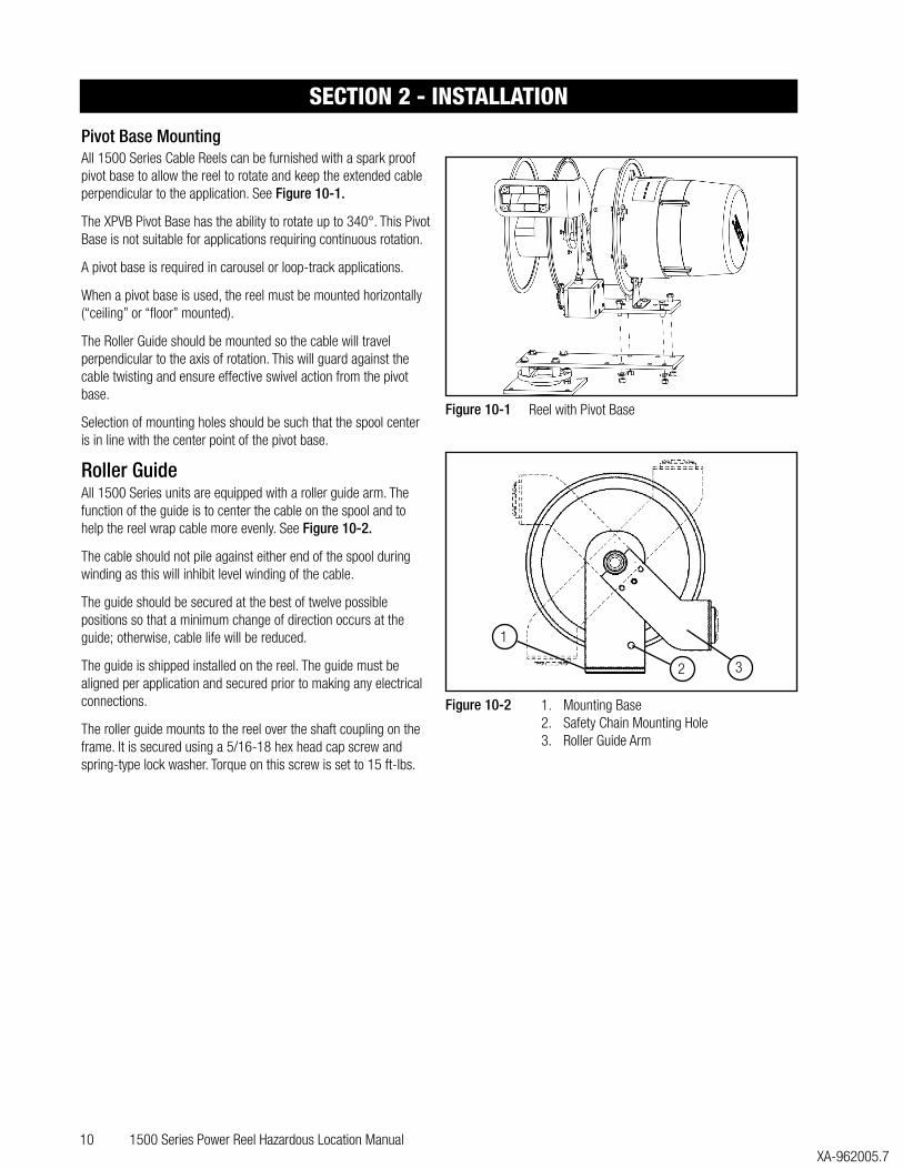
Pivot Base MountingAll 1500 Series Cable Reels can be furnished with a spark proof pivot base to allow the reel to rotate and keep the extended cable perpendicular to the application. See Figure 10-1.
The XPVB Pivot Base has the ability to rotate up to 340°. This Pivot Base is not suitable for applications requiring continuous rotation.
A pivot base is required in carousel or loop-track applications.
When a pivot base is used, the reel must be mounted horizontally (“ceiling” or “floor” mounted).
The Roller Guide should be mounted so the cable will travel perpendicular to the axis of rotation. This will guard against the cable twisting and ensure effective swivel action from the pivot base.
Selection of mounting holes should be such that the spool center is in line with the center point of the pivot base.
Roller GuideAll 1500 Series units are equipped with a roller guide arm. The function of the guide is to center the cable on the spool and to help the reel wrap cable more evenly. See Figure 10-2.
The cable should not pile against either end of the spool during winding as this will inhibit level winding of the cable.
The guide should be secured at the best of twelve possible positions so that a minimum change of direction occurs at the guide; otherwise, cable life will be reduced.
The guide is shipped installed on the reel. The guide must be aligned per application and secured prior to making any electrical connections.
The roller guide mounts to the reel over the shaft coupling on the frame. It is secured using a 5/16-18 hex head cap screw and spring-type lock washer. Torque on this screw is set to 15 ft-lbs.
SECTION 2 - INSTALLATION
Figure 10-1 Reel with Pivot Base
Figure 10-2 1. Mounting Base2. Safety Chain Mounting Hole3. Roller Guide Arm
1
32
1500 Series Power Reel Hazardous Location Manual 11 XA-962005.7
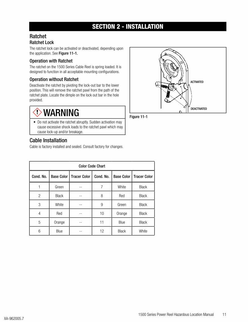
RatchetRatchet LockThe ratchet lock can be activated or deactivated, depending upon the application. See Figure 11-1.
Operation with RatchetThe ratchet on the 1500 Series Cable Reel is spring loaded. It is designed to function in all acceptable mounting configurations.
Operation without RatchetDeactivate the ratchet by pivoting the lock-out bar to the lower position. This will remove the ratchet pawl from the path of the ratchet plate. Locate the dimple on the lock out bar in the hole provided.
WARNING• Do not activate the ratchet abruptly. Sudden activation may
cause excessive shock loads to the ratchet pawl which may cause lock-up and/or breakage.
Cable InstallationCable is factory installed and sealed. Consult factory for changes.
Color Code Chart
Cond. No. Base Color Tracer Color Cond. No. Base Color Tracer Color
1 Green -- 7 White Black
2 Black -- 8 Red Black
3 White -- 9 Green Black
4 Red -- 10 Orange Black
5 Orange -- 11 Blue Black
6 Blue -- 12 Black White
SECTION 2 - INSTALLATION
DEACTIVATED
ACTIVATED
Figure 11-1

12 1500 Series Power Reel Hazardous Location ManualXA-962005.7
Spring Tension Adjustment
WARNING• Do not allow cable to retract without restraining the
retraction speed. Walk the cable back to the reel during the spring tension adjusting process. Always maintain two full cable wraps on drum at maximum cable extension, size cable accordingly.
1500 Series reels come with pre-tension from the factory. Some adjustment may be required to meet specific application requirements.
To assure that the cable will retract properly and operate under the correct tension for intended application; the reel should be tested.
1. Securely mount reel before testing with cable installed on drum and end of spool cable not connected.
2. Pull the cable out the intended travel distance and allow it to rewind. This procedure should be repeated five (5) to ten (10) times in order to set the spring. Walk the cable back to the reel during the spring tension adjusting process. See Figure 12-1.
3. With all the cable wound on the reel, grasp the end of the cable and rotate the drum and cable together in the direction of pay out in order to pre-tension the spring. See Figure 12-2.
» The number of pre-tension turns is determined by cable size and footage. Usually, four to sixteen turns is sufficient, but additional turns may be used if testing indicates that the cable will not fully retract as desired with just four turns.
4. Feed the end of the cable through the cable guide and pull the cable out the required length. Note: Total number of spool revolutions including the pre-tension turns, must not exceed the limits in the following table:
Spring model designation stated in reel description on ID tag invoice and packing slip.
Models w/#
Available Turns
Set up Turns
Models w/#
Available Turns
Set up Turns
J 23 4 K 29 8
JP 23 4 KP 29 8
JS 46 8 KS 58 16
Consult factory with any questions.
5. Repeat steps, if necessary, to add tension. To decrease tension, rotate drum and cable counter-clockwise. See Figure 12-3.
SECTION 2 - INSTALLATION
Travel
Direction
Figure 12-1 Rotate Spool While Holding Cable to Test the Spring Tension
Figure 12-2 Adding Spring TensionAdding Spring Tension
OneWrap
Figure 12-3

1500 Series Power Reel Hazardous Location Manual 13 XA-962005.7
Power ConnectionsProvide power source with over-current protection to prevent overheating of the reel and cable.
Reels are supplied with 6 foot feeder cords. Those cords are the same cable as is supplied on the spool. They are factory sealed with explosion proof potting compound and supplied with a watertight strain relief. If a conduit connection is required, the strain relief must be removed and conduit connections made.
SECTION 2 - INSTALLATION

14 1500 Series Power Reel Hazardous Location ManualXA-962005.7
• Do not exceed the voltage or amperage rating of the cable. Overheating, fire, damage to equipment or personal injury could result. • Do not allow cable to retract without restraining the retraction speed. • Operate the reel within the cable size and length and spring tensioning limits for which it was intended. • Keep two wraps of cable on the reel at maximum extension to avoid excessive tension on the cable and to prevent pullout of cable
from entrance watertight.
SECTION 3 - OPERATION
1500 Series Power Reel Hazardous Location Manual 15 XA-962005.7
WARNING• Be sure all power is off for all maintenance.
LubricationAll components requiring lubrication are lubricated for life at the factory. Additional lubrication is not be required.
Do not apply any lubricants or solvent cleaning agents to slip ring, brush or insulator surfaces.
InspectionsPeriodically check the reel for any loose or missing fasteners. Tighten or replace as necessary.
The slip ring assembly should be checked periodically as follows:
1. Clean to remove dust and dirt from the slip ring housing area and all slip ring assembly and brush surfaces.
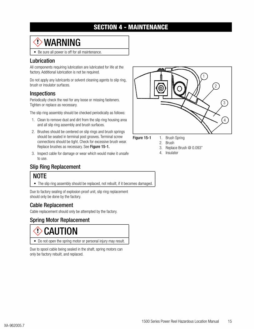
2. Brushes should be centered on slip rings and brush springs should be seated in terminal post grooves. Terminal screw connections should be tight. Check for excessive brush wear. Replace brushes as necessary. See Figure 15-1.
3. Inspect cable for damage or wear which would make it unsafe to use.
Slip Ring Replacement
NOTE• The slip ring assembly should be replaced, not rebuilt, if it becomes damaged.
Due to factory sealing of explosion proof unit, slip ring replacement should only be done by the factory.
Cable ReplacementCable replacement should only be attempted by the factory.
Spring Motor Replacement
CAUTION• Do not open the spring motor or personal injury may result.
Due to spool cable being sealed in the shaft, spring motors can only be factory rebuilt, and replaced.
SECTION 4 - MAINTENANCE
Figure 15-1 1. Brush Spring2. Brush3. Replace Brush @ 0.093”4. Insulator
1
3
2
4
16 1500 Series Power Reel Hazardous Location ManualXA-962005.7
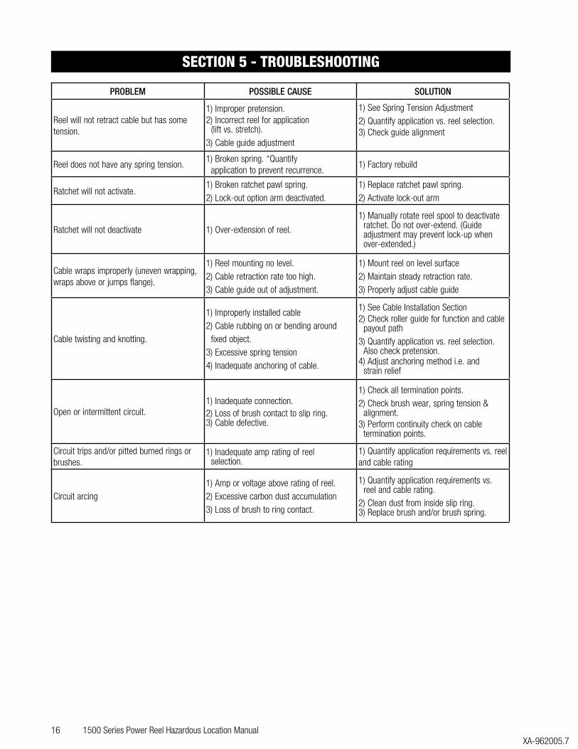
PROBLEM POSSIBLE CAUSE SOLUTION
Reel will not retract cable but has some tension.
1) Improper pretension.2) Incorrect reel for application (lift vs. stretch).3) Cable guide adjustment
1) See Spring Tension Adjustment2) Quantify application vs. reel selection.3) Check guide alignment
Reel does not have any spring tension.1) Broken spring. “Quantify application to prevent recurrence.
1) Factory rebuild
Ratchet will not activate.1) Broken ratchet pawl spring.2) Lock-out option arm deactivated.
1) Replace ratchet pawl spring.2) Activate lock-out arm
Ratchet will not deactivate 1) Over-extension of reel.
1) Manually rotate reel spool to deactivate ratchet. Do not over-extend. (Guide adjustment may prevent lock-up when over-extended.)
Cable wraps improperly (uneven wrapping, wraps above or jumps flange).
1) Reel mounting no level.2) Cable retraction rate too high.3) Cable guide out of adjustment.
1) Mount reel on level surface2) Maintain steady retraction rate.3) Properly adjust cable guide
Cable twisting and knotting.
1) Improperly installed cable2) Cable rubbing on or bending around fixed object.3) Excessive spring tension4) Inadequate anchoring of cable.
1) See Cable Installation Section2) Check roller guide for function and cable payout path3) Quantify application vs. reel selection. Also check pretension.4) Adjust anchoring method i.e. and strain relief
Open or intermittent circuit.1) Inadequate connection.2) Loss of brush contact to slip ring.3) Cable defective.
1) Check all termination points.2) Check brush wear, spring tension & alignment.3) Perform continuity check on cable termination points.
Circuit trips and/or pitted burned rings or brushes.
1) Inadequate amp rating of reel selection.
1) Quantify application requirements vs. reel and cable rating
Circuit arcing1) Amp or voltage above rating of reel.2) Excessive carbon dust accumulation3) Loss of brush to ring contact.
1) Quantify application requirements vs. reel and cable rating.2) Clean dust from inside slip ring.3) Replace brush and/or brush spring.
SECTION 5 - TROUBLESHOOTING
1500 Series Power Reel Hazardous Location Manual 17 XA-962005.7
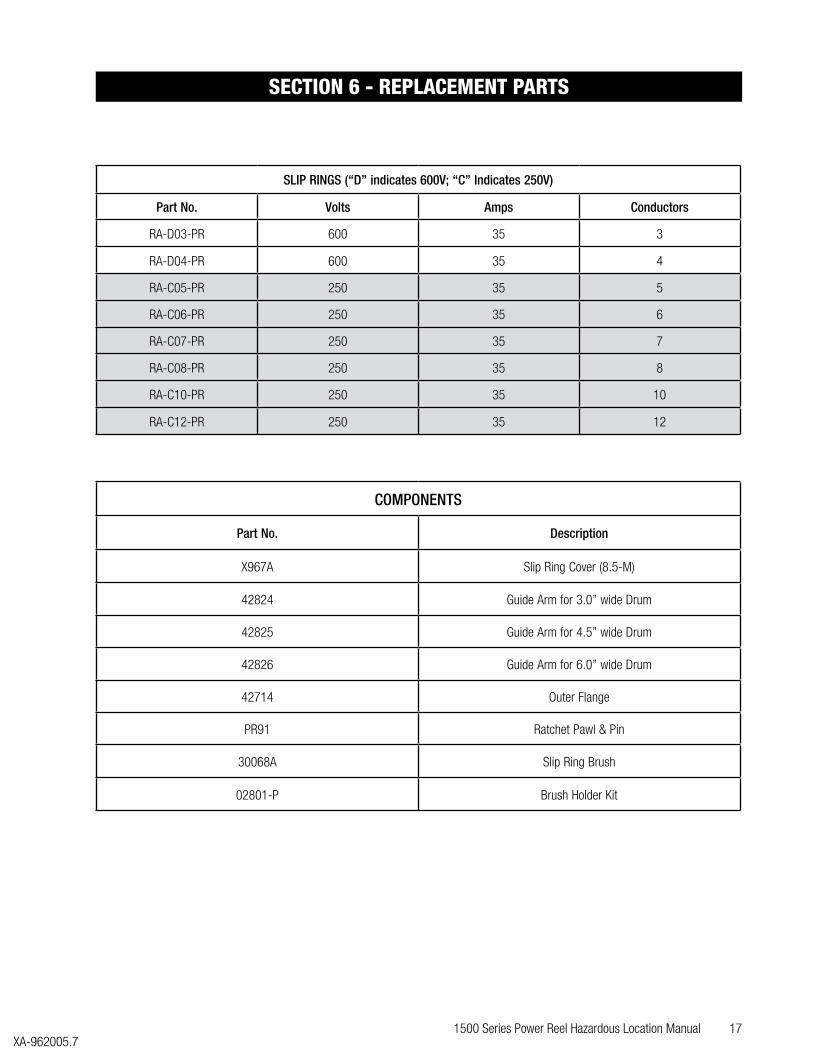
SLIP RINGS (“D” indicates 600V; “C” Indicates 250V)
Part No. Volts Amps Conductors
RA-D03-PR 600 35 3
RA-D04-PR 600 35 4
RA-C05-PR 250 35 5
RA-C06-PR 250 35 6
RA-C07-PR 250 35 7
RA-C08-PR 250 35 8
RA-C10-PR 250 35 10
RA-C12-PR 250 35 12
COMPONENTS
Part No. Description
X967A Slip Ring Cover (8.5-M)
42824 Guide Arm for 3.0” wide Drum
42825 Guide Arm for 4.5” wide Drum
42826 Guide Arm for 6.0” wide Drum
42714 Outer Flange
PR91 Ratchet Pawl & Pin
30068A Slip Ring Brush
02801-P Brush Holder Kit
SECTION 6 - REPLACEMENT PARTS

18 1500 Series Power Reel Hazardous Location ManualXA-962005.7
NOTES

1500 Series Power Reel Hazardous Location Manual 19 XA-962005.7
CONDUCTIX-WAMPFLER FIELD SERVICE
Need Field Service for our products? We Can Handle It!
Ask us for a quote on expert system installations, inspections, preventative maintenance, and repairs/retrofits.
As the world’s largest single source manufacturer of mobile electrification products, Conductix-Wamplfer has the unique ability to offer a degree of service not found anywhere else. Conductix-Wampfler's team of highly qualified service technicians and engineers have years of experience servicing our complete line of products.
We can provide:• Annual service contracts• Installation• Commissioning• Installation supervision to ensure your installers avoid common mistakes.• Troubleshooting to get you up and running.• Pre-planned inspections to complement your preventive maintenance program.
Call 1.800.521.4888 for further details.

© C
ondu
ctix-
Wam
pfler
| 20
18 |
Subj
ect t
o Te
chni
cal M
odifi
catio
ns W
ithou
t Prio
r Not
ice USA / LATIN AMERICA
10102 F Street
Omaha, NE 68127
Customer Support
Phone +1-800-521-4888
Phone +1-402-339-9300
Fax +1-402-339-9627
CANADA
18450 J.A. Bombardier
Mirabel, QC J7J 0H5
Customer Support
Phone +1-800-667-2487
Phone +1-450-565-9900
Fax +1-450-851-8591
MÉXICO
Calle Treviño 983-C
Zona Centro
Apodaca, NL México 66600
Customer Support
Phone (+52 81) 1090 9519
(+52 81) 1090 9025
(+52 81) 1090 9013
Fax (+52 81) 1090 9014
BRAZIL
Rua Luiz Pionti, 110
Vila Progresso
Itu, São Paulo, Brasil
CEP: 13313-534
Customer Support
Phone (+55 11) 4813 7330
Fax (+55 11) 4813 7357
1500 Series Power Reel Hazardous Location Manual XA-962005.7
Contact USA for our Global Sales Offices
www.conductix.us