Motor Management System - GE Grid Solutions · Motor Management System ... • Ship the unit by...
46
*1601-9030-A7* MM200 Motor Management System Low voltage motor protection and control GE Grid Solutions LISTED 52TL IND.CONT. EQ. E83849 Quick Start Guide MM200 Revision: 1.2x Manual P/N: 1601-9030-A7 Manual Order Code: GEK-113401F
Transcript of Motor Management System - GE Grid Solutions · Motor Management System ... • Ship the unit by...

*1601-9030-A7*
MM200Motor Management System
Low voltage motor protection and control
GEGrid Solutions
LISTED
52TL
IND.CONT. EQ.
E83849
Quick Start GuideMM200 Revision: 1.2xManual P/N: 1601-9030-A7Manual Order Code: GEK-113401F

© 2015 GE Multilin Incorporated. All rights reserved.
GE Multilin MM200 Motor Management System QuickStart Guide for revision 1.2x.
MM200 Motor Management System, EnerVista, EnerVista Launchpad, EnerVista MM300/MM200 Setup, and FlexLogic are registered trademarks of GE Multilin Inc.
The contents of this manual are the property of GE Multilin Inc. This documentation is furnished on license and may not be reproduced in whole or in part without the permission of GE Multilin. The content of this manual is for informational use only and is subject to change without notice.
Part number: 1601-9030-A7 (November 2015)

MM200 MOTOR MANAGEMENT SYSTEM – QUICK START GUIDE
StorageStore the unit indoors in a cool, dry place. If possible, store in the original packaging. Follow the storage temperature range outlined in the Specifications.
To avoid deterioration of electrolytic capacitors, power up units that are stored in a de-energized state once per year, for one hour continuously.
WarrantyFor products shipped as of 1 October 2013, GE warrants most of its GE manufactured products for 10 years. For warranty details including any limitations and disclaimers, see our Terms and Conditions at https://www.gegridsolutions.com/multilin/warranty.htm
For products shipped before 1 October 2013, the standard 24-month warranty applies.
RepairsThe firmware and software can be upgraded without return of the device to the factory.
For issues not solved by troubleshooting, the process to return the device to the factory for repair is as follows:
• Contact a GE Grid Solutions Technical Support Center. Contact information is found in the first chapter.
• Obtain a Return Materials Authorization (RMA) number from the Technical Support Center.
• Verify that the RMA and Commercial Invoice received have the correct information.
• Tightly pack the unit in a box with bubble wrap, foam material, or styrofoam inserts or packaging peanuts to cushion the item(s). You may also use double boxing whereby you place the box in a larger box that contains at least 5 cm of cushioning material.
• Ship the unit by courier or freight forwarder, along with the Commercial Invoice and RMA, to the factory.
Customers are responsible for shipping costs to the factory, regardless of whether the unit is under warranty.
• Fax a copy of the shipping information to the GE Grid Solutions service department.
Use the detailed return procedure outlined at
https://www.gegridsolutions.com/multilin/support/ret_proc.htm
The current warranty and return information are outlined at
https://www.gegridsolutions.com/multilin/warranty.htm
This product cannot be disposed of as unsorted municipal waste in the European Union. For proper recycling return this product to your supplier or a designated collection point. For more information go to www.recyclethis.info.

MM200 MOTOR MANAGEMENT SYSTEM – QUICK START GUIDE

TABLE OF CONTENTS
MM200 MOTOR MANAGEMENT SYSTEM – QUICKSTART GUIDE toc–1
Table of ContentsOVERVIEWCautions and Warnings ....................................................................................................................... 2
Safety words and definitions ......................................................................................................................2General Safety Precautions - MM200.....................................................................................................3
For Further Assistance.......................................................................................................................... 4
INSTALLATIONMechanical installation ........................................................................................................................ 5
Dimensions..........................................................................................................................................................5Product identification .....................................................................................................................................6Mounting ..............................................................................................................................................................7
Electrical installation ............................................................................................................................. 8Full-voltage non-reversing starter ........................................................................................................ 12RS485 connections ....................................................................................................................................... 13
Control panel...........................................................................................................................................14Basic control panel ....................................................................................................................................... 14
SETPOINTSUnderstanding setpoints...................................................................................................................17Configuration setpoints......................................................................................................................17
Motor setpoints .............................................................................................................................................. 17Current transformers................................................................................................................................... 19
PROTECTION ELEMENTSThermal protection...............................................................................................................................21
Overload curve ...............................................................................................................................................21
COMMUNICATIONS INTERFACES
SPECIFICATIONSProtection specifications ...................................................................................................................27User interface specifications ...........................................................................................................28Control specifications .........................................................................................................................29Inputs specifications............................................................................................................................29Outputs specifications........................................................................................................................30Power supply specifications ............................................................................................................30Communications specifications.....................................................................................................30Testing and certification ....................................................................................................................31Physical specifications........................................................................................................................32Environmental specifications ..........................................................................................................32
MM200 ORDER CODESExample of an MM200 order code................................................................................................35
MAINTENANCEGeneral Maintenance..........................................................................................................................37
In-service maintenance ............................................................................................................................. 37

toc–2 MM200 MOTOR MANAGEMENT SYSTEM – QUICKSTART GUIDE
TABLE OF CONTENTS
Out-of-service maintenance ....................................................................................................................37Unscheduled maintenance (system interruption) ..........................................................................38
Backup and restore settings ...........................................................................................................38Backing up settings.......................................................................................................................................38Restoring settings ..........................................................................................................................................38Upgrading firmware .....................................................................................................................................39Upgrading the software..............................................................................................................................40Uninstalling files and clearing data.......................................................................................................40

MM200 MOTOR MANAGEMENT SYSTEM – QUICK START GUIDE 1
MM200 Motor Management System
Chapter 1: Overview
GEGrid Solutions
Overview
The MM200 is a motor protection and control system designed specifically for low-voltage motor applications. The MM200 provides the following key benefits.
• Protection, control, and communication options to suit low-voltage motor applications.
• Small footprint designed specifically for IEC and NEMA MCC applications.
• DIN rail Mounting.
• Multiple communication protocols allows simple integration into monitoring and control systems.
• Optional basic control panel interface provides local control and access to system information.

2 MM200 MOTOR MANAGEMENT SYSTEM – QUICK START GUIDE
CAUTIONS AND WARNINGS CHAPTER 1: OVERVIEW
Figure 1-1: Single line diagram
Table 1-1: MM200 protection functions
Cautions and Warnings
Before attempting to install or use the device, review all safety indicators in this document to help prevent injury, equipment damage, or downtime.
Safety words and definitionsThe following symbols used in this document indicate the following conditions
RS485 - Modbus RTU
Profibus/DeviceNet
52
METERING
A
51R 49 37 46
50G
MOTOR
LOAD
Temperature
Thermistor
Phase CT 3
Ground CT 1
Power Fuse
BUS
MM200MOTOR MANAGEMENT SYSTEM
Contactor
888739A2.CDR
LO: 7 inputs and 3 outputsHI: 6 inputs and 3 outputs
LO: 24 V DCHI: 84 to 250 V DC / 60 to 300 V AC
ANSI device Description
37 Undercurrent and underpower
46 Current unbalance
49 Thermal overload
50G Ground instantaneous overcurrent
51R Locked/stalled rotor, mechanical jam

CHAPTER 1: OVERVIEW CAUTIONS AND WARNINGS
MM200 MOTOR MANAGEMENT SYSTEM – QUICK START GUIDE 3
DANGER: Indicates a hazardous situation which, if not avoided, will result in death or serious injury.
IMPORTANT: Indicates a hazardous situation which, if not avoided, could result in death or serious injury.
CAUTION: Indicates a hazardous situation which, if not avoided, could result in minor or moderate injury.
NOTE
NOTE: Indicates practices not related to personal injury.
General Safety Precautions - MM200CAUTION: Failure to observe and follow the instructions provided in the equipment manual(s)
could cause irreversible damage to the equipment and could lead to property damage, personal injury and/or death.
Before attempting to use the equipment, it is important that all danger and caution indicators are reviewed.
If the equipment is used in a manner not specified by the manufacturer or functions abnormally, proceed with caution. Otherwise, the protection provided by the equipment may be impaired and can result in Impaired operation and injury.
Caution: Hazardous voltages can cause shock, burns or death.
Installation/service personnel must be familiar with general device test practices, electrical awareness and safety precautions must be followed.
Before performing visual inspections, tests, or periodic maintenance on this device or associated circuits, isolate or disconnect all hazardous live circuits and sources of electric power.
Failure to shut equipment off prior to removing the power connections could expose you to dangerous voltages causing injury or death.
All recommended equipment that should be grounded and must have a reliable and un-compromised grounding path for safety purposes, protection against electromagnetic interference and proper device operation.
Equipment grounds should be bonded together and connected to the facility’s main ground system for primary power.
Keep all ground leads as short as possible.
At all times, equipment ground terminal must be grounded during device operation and service.
In addition to the safety precautions mentioned all electrical connections made must respect the applicable local jurisdiction electrical code.
Before working on CTs, they must be short-circuited.

4 MM200 MOTOR MANAGEMENT SYSTEM – QUICK START GUIDE
FOR FURTHER ASSISTANCE CHAPTER 1: OVERVIEW
For Further Assistance
For product support, contact the information and call center as follows:GE Grid Solutions650 Markland StreetMarkham, OntarioCanada L6C 0M1Worldwide telephone: +1 905 927 7070Europe/Middle East/Africa telephone: +34 94 485 88 54North America toll-free: 1 800 547 8629Fax: +1 905 927 5098Worldwide e-mail: [email protected] e-mail: [email protected]: http://www.gegridsolutions.com/multilin

MM200 MOTOR MANAGEMENT SYSTEM – QUICK START GUIDE 5
MM200 Motor Management System
Chapter 2: Installation
GEGrid Solutions
Installation
Mechanical installation
This section describes the mechanical installation of the MM200 system, including dimensions for mounting.
DimensionsThe MM200 is packaged in a fixed format divided into three specific sections.The dimensions of the MM200 are shown below. Additional dimensions for mounting are shown in the following sections.
6 MM200 MOTOR MANAGEMENT SYSTEM – QUICK START GUIDE
MECHANICAL INSTALLATION CHAPTER 2: INSTALLATION
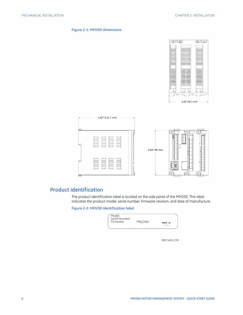
Figure 2-1: MM200 dimensions
Product identificationThe product identification label is located on the side panel of the MM200. This label indicates the product model, serial number, firmware revision, and date of manufacture.
Figure 2-2: MM200 Identification label
888748A1.CDR
Model:
Serial Number:
Firmware: Mfg.Date:

CHAPTER 2: INSTALLATION MECHANICAL INSTALLATION
MM200 MOTOR MANAGEMENT SYSTEM – QUICK START GUIDE 7
Figure 2-3: MM200 ratings label
MountingThe MM200 is DIN rail mounted.The standard DIN rail mounting is illustrated below. The DIN rail conforms to EN 50022.
CAUTION: To avoid the potential for personal injury due to fire hazards, ensure the unit is mounted in a safe location and/or within an appropriate enclosure.
Figure 2-4: DIN rail mounting

8 MM200 MOTOR MANAGEMENT SYSTEM – QUICK START GUIDE
ELECTRICAL INSTALLATION CHAPTER 2: INSTALLATION
Electrical installation
This section describes the electrical installation of the MM200 system. An overview of the MM200 terminal connections is shown below.
CAUTION: MM200 is not to be used in any way other than described in this manual.
Figure 2-5: MM200 terminal connection overview
A Modbus RTU RS485 port, a thermistor input, and a 50:0.025 CBCT input are provided. Profibus and Devicenet are provided as options.
Table 2-1: Slot position
Figure 2-6: MM200 terminal connection torque rating
Slot Type
A PSU/Inputs/Control Panel
B CPU/CTs
C Outputs/CBCT/Thermistor/RS485
Control Panel
Profibus or DeviceNetOptional fieldbus protocols
888740A2.CDRCTs
PSU
Inputs
RS485Thermistor
CBCT
2 x Form A1 x Form C
connector screw torque
CT 4.5 lb-in
IPS, output 5.0 lb-in
Fieldbus, 3.0 lb-inThermistor & RS485

CHAPTER 2: INSTALLATION ELECTRICAL INSTALLATION
MM200 MOTOR MANAGEMENT SYSTEM – QUICK START GUIDE 9
CAUTION: Use gauge size appropriate for the voltage and current draw of the device.
Table 2-2: Wire Gauge Sizes
NOTE
NOTE: It is recommended that you install a circuit disconnection system for control power, near the device, which should be easily accessible after installation of the unit. This is in case an emergency power shut-down of the unit is required.
Figure 2-7: Top and Rear panel arrangement
The MM200 I/O terminals are labeled with a two-character identifier. The first character identifies slot position and the second identifies the terminal.
Slot A PSU and Inputs 12 AWG (2.5 mm2) (5.00mm pitch terminals)1
1.Wire gauge size remains constant; increased pitch distance reflects higher voltage rating.
Slot B Fieldbus,
CT Connections
16 AWG (1.5 mm2) (3.50mm pitch terminals)12 AWG (2.5 mm2) (7.62mm pitch terminals)1
Slot C RS485 & ThermistorOutput Relays, CBCT
16 AWG (1.5 mm2) (3.50mm pitch terminals12 AWG (2.5 mm2) (5.00mm pitch terminals)1

10 MM200 MOTOR MANAGEMENT SYSTEM – QUICK START GUIDE
ELECTRICAL INSTALLATION CHAPTER 2: INSTALLATION
CAUTION: Check the voltage rating of the unit before applying control power! Control power outside of the operating range of the power supply will damage the MM200.
Figure 2-8: CBCT ground CT connection
HILO888351A3-P2
888741A3.CDR
A
C
B
Contactor
Contactor
TOCONTROL
PANEL
C1
C2
C4
C3
C5
C6
MM200Motor Management System
C8
C9
C10
C7
Two form-A
contact outputs
CONTACT OUTPUT 2
One form-C
contact output
CONTACT OUTPUT 1
CONTACT OUTPUT 3
THERMISTOR
CBCT
RS485
R
I
-+
-
+
C
B3 B4 B5 B6 B7 B8
I R I R I R
CT1 CT2 CT3
CT MODULE
RJ45
PROFIBUS OR DEVICENET
V- L H V+
MOTOR
M
M
SG
LO and HI inputs- see below -

CHAPTER 2: INSTALLATION ELECTRICAL INSTALLATION
MM200 MOTOR MANAGEMENT SYSTEM – QUICK START GUIDE 11
Figure 2-9: CBCT ground CT connection - LO and HI inputs
The exact placement of a zero-sequence CT to detect only ground fault current is shown below. If the core balance CT is placed over shielded cable, capacitive coupling of phase current into the cable shield during motor starts may be detected as ground current unless the shield wire is also passed through the CT window. Twisted-pair cabling on the zero-sequence CT is recommended.
Figure 2-10: Core balance ground CT installation, shielded cable
M
-+
A1
A2
A4
A3
A5
A6
A8
A9
A10
A7
+-
24 VD
C C
ON
TAC
T INP
UTS
CO
NTR
OL
PO
WE
R (V
DC
)
CONTROLPOWER24 VDC
FIELD STOP
FIELD START
RESET
M
N
L
A1
A2
A4
A3
A5
A6
A8
A9
A10
L
N
VAC
CO
NTA
CT IN
PU
TS
CO
NTR
OL
PO
WE
R (VA
C)
CONTROLPOWER
VAC
FIELD STOP
FIELD START
RESET
NR
LO HI
888742A3.cdr
RETURN
NOTE: AC power and AC input wiring shown.
POWER CABLE
TO MOTOR
TO STARTER
GROUND BUS
CABLE LUGS
TO SOURCE
TERMINATION
(TWISTED PAIR)
SPLIT-BOLT CONNECTOR
888712A1.CDR
CORE BALANCE CT
SECONDARY CONNECTION
TO MM200 IED
IMPORTANT: FOR SHIELDED
CABLE, THE GROUND WIRE
MUST PASS THROUGH THE
CT WINDOW.
50:0.025 CORE BALANCE CT
FOR GROUND SENSING
STRESS CONE
SHIELD GROUND
CONNECTION
BOTTOM OF
MOTOR STARTER
COMPARTMENT

12 MM200 MOTOR MANAGEMENT SYSTEM – QUICK START GUIDE
ELECTRICAL INSTALLATION CHAPTER 2: INSTALLATION
Figure 2-11: Core balance ground CT installation, unshielded cable
Full-voltage non-reversing starterFigure 2-12: Full-voltage non-reversing starter wiring
POWER CABLE
TO MOTOR
50:0.025 CORE BALANCE CT
FOR GROUND CT SENSING
TO STARTER
GROUND BUS
CABLE LUGS TO SOURCE
TERMINATION
(TWISTED-PAIR)
888713A1.CDR
GROUND CONDUCTOR DOES
NOT PASS THROUGH CT, AS THE
CT IS NOT MOUNTED OVER
GROUND WITHIN THE CABLE
JACKET.
BOTTOM OF
MOTOR STARTER
COMPARTMENT
CORE BALANCE CT
SECONDARY CONNECTION
TO MM200 IED
888741A3.CDR
A
C
B
Contactor
Contactor
TOCONTROL
PANEL
C1
C2
C4
C3
C5
C6
MM200Motor Management System
C8
C9
C10
C7
Two form-A
contact outputs
CONTACT OUTPUT 2
One form-C
contact output
CONTACT OUTPUT 1
CONTACT OUTPUT 3
THERMISTOR
CBCT
RS485
R
I
-+
-
+
C
B3 B4 B5 B6 B7 B8
I R I R I R
CT1 CT2 CT3
CT MODULE
RJ45
PROFIBUS OR DEVICENET
V- L H V+
MOTOR
M
M
SG
LO and HI inputs- see below -

CHAPTER 2: INSTALLATION ELECTRICAL INSTALLATION
MM200 MOTOR MANAGEMENT SYSTEM – QUICK START GUIDE 13
Figure 2-13: LO and HI inputs
The full-voltage non-reversing starter type is a full voltage or across-the-line non-reversing starter.When a start control is received, the pre-contactor relay (if any) is picked up for the set pre-contactor time. When the pre-contactor timer times out, relay contact output 1 closes and seals-in, picking up contactor M, which starts the motor. When a stop control is received, relay contact output 1 drops out, contactor M drops out, and the motor stops. The pre-contactor is omitted on forced starts (for example, External Start).
RS485 connections
Figure 2-14: Typical RS485 connection
M
-
+
A1
A2
A4
A3
A5
A6
A8
A9
A10
A7
+
-
24
VD
CC
ON
TA
CT
INP
UT
S
CO
NT
RO
L
PO
WE
R(V
DC
)
CONTROLPOWER24 VDC
FIELD STOP
FIELD START
RESET
M
N
L
A1
A2
A4
A3
A5
A6
A8
A9
A10
L
N
VA
CC
ON
TA
CT
INP
UT
S
CO
NT
RO
L
PO
WE
R(V
AC
)
CONTROLPOWER
VAC
FIELD STOP
FIELD START
RESET
NR
LO HI
888742A1.cdr
RETURN
NOTE: AC power and AC input wiring shown.Connect NR to Neutral if DC power supply used.
SCADA, PLC, OR
PERSONAL COMPUTER
COM
OPTOCOUPLER
DATA
MM200 IEDSHIELD
888745A1.CDR
UP TO 32 MM200
OR OTHER IEDs,
MAXIMUM CABLE
LENGTH OF
1200 m (4000 ft.)
LAST
DEVICE
(*) TERMINATING IMPEDANCE AT EACH END
(typically 120 ohms and 1 nF)
TWISTED PAIR
ZT
(*)
RS485 +
RS485 -
COMMON
RS485 +
RS485 -
COMMON
IED
RS485 +
IED
RS485 -
COMMON
GROUND THE SHIELD AT THE
SCADA/PLC/COMPUTER ONLY
OR THE MM200 ONLY
DATA
OPTOCOUPLER
ZT
(*) +
-
C

14 MM200 MOTOR MANAGEMENT SYSTEM – QUICK START GUIDE
CONTROL PANEL CHAPTER 2: INSTALLATION
One two-wire RS485 port is provided. Up to 32 MM200 IEDs can be daisy-chained together on a communication channel without exceeding the driver capability. For larger systems, additional serial channels must be added. Commercially available repeaters can also be used to add more than 32 relays on a single channel. Suitable cable should have a characteristic impedance of 120 ohms and total wire length should not exceed 1200 meters (4000 ft.). Commercially available repeaters will allow for transmission distances greater than 1200 meters.Voltage differences between remote ends of the communication link are not uncommon. For this reason, surge protection devices are internally installed across all RS485 terminals. Internally, an isolated power supply with an optocoupled data interface is used to prevent noise coupling.
CAUTION: To ensure that all devices in a daisy-chain are at the same potential, it is imperative that the common terminals of each RS485 port are tied together and grounded only once, at the master or at the MM200. Failure to do so may result in intermittent or failed communications.
The source computer/PLC/SCADA system should have similar transient protection devices installed, either internally or externally. Ground the shield at one point only, as shown in the figure above, to avoid ground loops.Correct polarity is also essential. The MM200 IEDs must be wired with all the positive (+) terminals connected together and all the negative (–) terminals connected together. Each relay must be daisy-chained to the next one. Avoid star or stub connected configurations. The last device at each end of the daisy-chain should be terminated with a 120 ohm ¼ watt resistor in series with a 1 nF capacitor across the positive and negative terminals. Observing these guidelines will ensure a reliable communication system immune to system transients.
Control panel
This section provides an overview of the interfacing methods available with the MM200. For additional details on interface parameters (for example, settings, actual values, etc.), refer to the individual chapters.There are two methods of interfacing with the MM200 Motor Management System.
• Via the basic control panel.
• Via the EnerVista MM200 Setup software.
NOTE
NOTE: For full details on handling the EnerVista MM200 Setup software, please use the EnerVista MM200 Setup Software Guide which accompanies this manual.
Basic control panelThe MM200 basic control panel provides the basic start and stop panel functionality, as well as a series of LED indications. The basic control panel is illustrated below.
CHAPTER 2: INSTALLATION CONTROL PANEL
MM200 MOTOR MANAGEMENT SYSTEM – QUICK START GUIDE 15
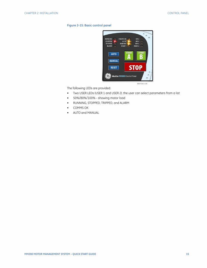
Figure 2-15: Basic control panel
The following LEDs are provided:
• Two USER LEDs (USER 1 and USER 2). the user can select parameters from a list
• 50%/80%/100% - showing motor load
• RUNNING, STOPPED, TRIPPED, and ALARM
• COMMS OK
• AUTO and MANUAL
888750A1.CDR

16 MM200 MOTOR MANAGEMENT SYSTEM – QUICK START GUIDE
CONTROL PANEL CHAPTER 2: INSTALLATION

MM200 MOTOR MANAGEMENT SYSTEM – QUICK START GUIDE 17
MM200 Motor Management System
Chapter 3: Setpoints
GEGrid Solutions
Setpoints
Understanding setpoints
Setpoints can be modified via RS485, using the EnerVista MM200 Setup program.CAUTION: Setpoints may be changed while the motor is running; however it is not recommended
to change important protection parameters without first stopping the motor.
Setpoints will remain stored indefinitely in the internal non-volatile memory even when control power to the unit is removed. Protection parameters are based on the entered data. This data must be complete and accurate for the given system for reliable protection and operation of the motor.
Configuration setpoints
The configuration setpoints contains data on motor configuration as well as system setup, inputs, outputs, communications, and CTs.
• Motor (setpoints related to motor configuration).
• CT (setpoints related to CT configuration).
• Inputs (setpoints related to digital input configuration)
• Outputs (setpoints related to digital output configuration)
• Comms (setpoints related to communications configuration)
• System (setpoints related to MM200 system configuration, such as the faceplate LEDs)
• Counters (setpoints related to the digital counters)
Motor setpointsThe MM200 starter function is responsible for executing the motor startup sequence, including the pre-contactor start warning. The MM200 provides three pre-defined starters.
• Full-voltage non-reversing

18 MM200 MOTOR MANAGEMENT SYSTEM – QUICK START GUIDE
CONFIGURATION SETPOINTS CHAPTER 3: SETPOINTS
• Full-voltage reversing
• Two-speed
NOTE
NOTE: By selecting a pre-defined starter, inputs and outputs are automatically assigned.
Common motorsetpoints
Several motor setpoints are dependent on the chosen starter type. The setpoints shown below are common to all starter types.
Motor NameRange: up to 20 alphanumeric charactersDefault: Motor Name
This setpoint specifies a name for the motor. This name will appear in the actual values.
Starter Type (Mandatory setpoint)Range: None, FV Non-Reversing, FV Reversing, Two SpeedDefault: FV Non-Reversing
This setpoint selects the starter type. The relay is essentially disabled when the value is set to “None”. Figure 1 illustrates typical starter timing beginning from the stopped state for all starter types.
Motor FLA (Mandatory setpoint)Range: 0.5 to 1000.0 amps in steps of 0.1Default: OFF
This setpoint must be specified for motor protection. The value may be taken from the motor nameplate data sheets.
Supply Frequency (Mandatory setpoint)Range: 50 Hz, 60 HzDefault: 60 Hz
This setpoint specifies the nominal system frequency.
The following sections provide additional information for each starter type.

CHAPTER 3: SETPOINTS CONFIGURATION SETPOINTS
MM200 MOTOR MANAGEMENT SYSTEM – QUICK START GUIDE 19
Figure 3-1: Typical starter timing
Current transformersThe following setpoints are available to configure the current and voltage transformers.
Phase CT Type (Mandatory setpoint)Range: None, 1 A Secondary, 5 A Secondary, Direct ConnectDefault: Direct Connect
This setpoint specifies the phase CT connection type. The “Direct Connect” value indicates that no phase CTs are used; instead, motor phase current passes directly through the relay. The “Direct Connect” selection should never be used where full load current is greater than 5.0 amps.
NOTE
NOTE: If Direct Connect is selected and the FLA is set >5 A, a "FLA too high" message will be displayed on the Status page.
CT Primary TurnsRange: 1 to 10Default: 1
For smaller motors where the drawn current is very low, the motor leads may be wrapped through the CT Primary with several turns thereby increasing the current seen by the MM200 and as a result increasing the accuracy of the measurement. The value of this setting should equal the number of turns on the CT Primary to display the correct current value. Internally the current measurement will be divided by this setting.
Contactor B Relay
Contactor A Relay
Pre-contactor
Starting
Running
Sta
rtA
Sta
rtB
Sta
rtA
Sto
p
Motor Current
Fu
llV
olt
ag
eN
on
-re
ve
rsin
g
Contactor B Relay
Contactor A Relay
Pre-contactor
Starting
Running
Motor Current
Fu
llV
olt
ag
eR
ev
ers
ing
Contactor B Relay
Contactor A Relay
Pre-contactor
Starting
Running
Motor Current
Tw
oS
pe
ed
Sta
rte
r
P
T
P
P
T
T
P - Pre-contactor Time setting
T - Transfer Time setting
R - Ramp Down Time setting
888710A1.CDR

20 MM200 MOTOR MANAGEMENT SYSTEM – QUICK START GUIDE
CONFIGURATION SETPOINTS CHAPTER 3: SETPOINTS
CT Primary (Mandatory setpoint)Range: 5 to 1000 amps in steps of 1Default: 5 amps
This setpoint specifies the phase CT primary current. It should never be less than the full load current, and preferably no greater than twice than the full load current.
NOTE
NOTE: This setpoint is displayed only if the phase CT is selected to 1 A secondary or 5 A secondary.
High Speed CT PrimaryRange: 5 to 1000 amps in steps of 1Default: 5 amps
This setpoint specifies the phase CT primary current when the motor is running at high speed. It should never be less than the high speed full load current, and preferably no greater than twice than the high speed full load current.
NOTE
NOTE: This setpoint is displayed only if the phase CT is selected as 1 A secondary or 5 A secondary and the motor starter type is two-speed.

MM200 MOTOR MANAGEMENT SYSTEM – QUICK START GUIDE 21
MM200 Motor Management System
Chapter 4: Protection elements
GEGrid Solutions
Protection elements
Thermal protection
The primary protective function of the MM200 is the thermal model. The MM200 integrates stator and rotor heating into a single model. The rate of motor heating is gauged by measuring the terminal currents. The present value of the accumulated motor heating is maintained in the Thermal Capacity Used actual value register. When the motor is in overload, the motor temperature and thermal capacity used will rise. A trip occurs when the thermal capacity used reaches 100%. When the motor is stopped and is cooling to ambient, the thermal capacity used decays to zero. If the motor is running normally, the motor temperature will eventually stabilize at some steady state temperature, and the thermal capacity used increases or decreases to some corresponding intermediate value, which accounts for the reduced amount of thermal capacity left to accommodate transient overloads.The thermal model consists of four key elements.
• Hot/cold biasing that accounts for normal temperature rise.
• An overload curve that accounts for the rapid heating that occurs during stall, acceleration, and overload.
• Cooling rate that accounts for heat dissipation.
• Thermal protection reset that controls recovery from thermal trips and lockouts.
Each of these categories are described in the following sub-sections.
Overload curveThe overload curve accounts for the rapid motor heating that occurs during stall, acceleration, and overload. Specifically, the overload curve controls the rate of increase of Thermal Capacity Used whenever the equivalent motor heating current is greater than 1.01 times the full load current setpoint. The curve is defined by the following equation and

22 MM200 MOTOR MANAGEMENT SYSTEM – QUICK START GUIDE
THERMAL PROTECTION CHAPTER 4: PROTECTION ELEMENTS
reflects that overload heating largely swamps the cooling, and this heating is primarily due to resistive losses in the stator and the rotor windings (said losses being proportional to the square of the current).
Eq. 1
Eq. 2
In the above equation,
• The trip time represents the time (in seconds) for the MM200 to trip, given the motor starts cold and the current is constant.
• The multiplier represents the value of the Curve Multiplier setpoint. This setpoint can be used to adjust the curve to match the thermal characteristics of the motor.
• Iav represents the equivalent motor heating current in per-unit values on a full load current base. The value of IAV is limited in this equation to 8.0 to prevent the overload from acting as an instantaneous element and responding to short circuits.
For example, a motor with a stall current (also known as locked rotor current) of 8 times its FLA, with a curve multiplier of 7, if stalled from a cold state, trips in the following amount of time.
Eq. 3
This would respect a safe stall cold time of 10 seconds.The standard overload curves are displayed below.
�
IAV
PickupFLA
�
�
Curve MultipliertimeTrip
2.2116623
0.02530337 x (Pickup - 1) + 0.05054758 x (Pickup -1)2
�
�
Curve MultipliertimeTrip
2.2116623
0.02530337 x (Pickup - 1) + 0.05054758 x (Pickup -1)2
�
�
7 2.2116623
0.02530337 x (8 - 1) + 0.05054758 x (8 -1)2
� 9.714 seconds

CHAPTER 4: PROTECTION ELEMENTS THERMAL PROTECTION
MM200 MOTOR MANAGEMENT SYSTEM – QUICK START GUIDE 23
Figure 4-1: Standard overload curves
The trip times for the standard overload curves are tabulated below.
Table 4-1: Standard overload curve trip times (in seconds)PICKUP (× FLA)
STANDARD CURVE MULTIPLIERS
× 1 × 2 × 3 × 4 × 5 × 6 × 7 × 8 × 9 × 10 × 11 × 12 × 13 × 14 × 15
1.01
4353.6
8707.2
13061
17414
21768
26122
30475
34829
39183
43536
47890
52243
56597
60951
65304
1.05
853.71
1707.4
2561.1
3414.9
4268.6
5122.3
5976.0
6829.7
7683.4
8537.1
9390.8
10245
11098
11952
12806
1.10
416.68
833.36
1250.0
1666.7
2083.4
2500.1
2916.8
3333.5
3750.1
4166.8
4583.5
5000.2
5416.9
5833.6
6250.2
1.20
198.86
397.72
596.58
795.44
994.30
1193.2
1392.0
1590.9
1789.7
1988.6
2187.5
2386.3
2585.2
2784.1
2982.9
1.30
126.80
253.61
380.41
507.22
634.02
760.82
887.63
1014.4
1141.2
1268.0
1394.8
1521.6
1648.5
1775.3
1902.1
1.40
91.14
182.27
273.41
364.55
455.68
546.82
637.96
729.09
820.23
911.37
1002.5
1093.6
1184.8
1275.9
1367.0
x1
x15
100000
10000
1000
100
10
1.00
0.10 1.00
MULTIPLE OF FULL LOAD AMPS
TIM
EIN
SE
CO
ND
S
10 100 1000
888731A2.CDR

24 MM200 MOTOR MANAGEMENT SYSTEM – QUICK START GUIDE
THERMAL PROTECTION CHAPTER 4: PROTECTION ELEMENTS
The following tables illustrate the relation between GE Multilin MM2 and MM3 curve numbers, NEMA curves, and the MM200 curve multipliers.
Table 4-2: MM2 and MM3 curve numbers and MM200 curve multipliers
Table 4-3: NEMA curves and MM200 curve multipliers
1.50
69.99
139.98
209.97
279.96
349.95
419.94
489.93
559.92
629.91
699.90
769.89
839.88
909.87
979.86
1049.9
1.75
42.41
84.83
127.24
169.66
212.07
254.49
296.90
339.32
381.73
424.15
466.56
508.98
551.39
593.81
636.22
2.00
29.16
58.32
87.47
116.63
145.79
174.95
204.11
233.26
262.42
291.58
320.74
349.90
379.05
408.21
437.37
2.25
21.53
43.06
64.59
86.12
107.65
129.18
150.72
172.25
193.78
215.31
236.84
258.37
279.90
301.43
322.96
2.50
16.66
33.32
49.98
66.64
83.30
99.96
116.62
133.28
149.94
166.60
183.26
199.92
216.58
233.24
249.90
2.75
13.33
26.65
39.98
53.31
66.64
79.96
93.29
106.62
119.95
133.27
146.60
159.93
173.25
186.58
199.91
3.00
10.93
21.86
32.80
43.73
54.66
65.59
76.52
87.46
98.39
109.32
120.25
131.19
142.12
153.05
163.98
3.25
9.15 18.29
27.44
36.58
45.73
54.87
64.02
73.16
82.31
91.46
100.60
109.75
118.89
128.04
137.18
3.50
7.77 15.55
23.32
31.09
38.87
46.64
54.41
62.19
69.96
77.73
85.51
93.28
101.05
108.83
116.60
3.75
6.69 13.39
20.08
26.78
33.47
40.17
46.86
53.56
60.25
66.95
73.64
80.34
87.03
93.73
100.42
4.00
5.83 11.66
17.49
23.32
29.15
34.98
40.81
46.64
52.47
58.30
64.13
69.96
75.79
81.62
87.45
4.25
5.12 10.25
15.37
20.50
25.62
30.75
35.87
41.00
46.12
51.25
56.37
61.50
66.62
71.75
76.87
4.50
4.54 9.08 13.63
18.17
22.71
27.25
31.80
36.34
40.88
45.42
49.97
54.51
59.05
63.59
68.14
4.75
4.06 8.11 12.17
16.22
20.28
24.33
28.39
32.44
36.50
40.55
44.61
48.66
52.72
56.77
60.83
5.00
3.64 7.29 10.93
14.57
18.22
21.86
25.50
29.15
32.79
36.43
40.08
43.72
47.36
51.01
54.65
5.50
2.99 5.98 8.97 11.96
14.95
17.94
20.93
23.91
26.90
29.89
32.88
35.87
38.86
41.85
44.84
6.00
2.50 5.00 7.49 9.99 12.49
14.99
17.49
19.99
22.48
24.98
27.48
29.98
32.48
34.97
37.47
6.50
2.12 4.24 6.36 8.48 10.60
12.72
14.84
16.96
19.08
21.20
23.32
25.44
27.55
29.67
31.79
7.00
1.82 3.64 5.46 7.29 9.11 10.93
12.75
14.57
16.39
18.21
20.04
21.86
23.68
25.50
27.32
7.50
1.58 3.16 4.75 6.33 7.91 9.49 11.08
12.66
14.24
15.82
17.41
18.99
20.57
22.15
23.74
8.00
1.39 2.78 4.16 5.55 6.94 8.33 9.71 11.10
12.49
13.88
15.27
16.65
18.04
19.43
20.82
MM2 and MM3 curve number 1 2 3 4 5 6 7 8
MM200 curve multiplier 1 2 3 4 7 9 12 15
NEMA curve Class 10 Class 15 Class 20 Class 30
MM200 curve multiplier 4 6 8 12
PICKUP (× FLA)
STANDARD CURVE MULTIPLIERS
× 1 × 2 × 3 × 4 × 5 × 6 × 7 × 8 × 9 × 10 × 11 × 12 × 13 × 14 × 15

MM200 MOTOR MANAGEMENT SYSTEM – QUICK START GUIDE 25
MM200 Motor Management System
Chapter 5: Communications interfaces
GEGrid Solutions
Communications interfaces
The MM200 has two communications interfaces:
• RS485
• Fieldbus
NOTE
NOTE: Setpoint changes related to RS485, DeviceNet, and Profibus, require a power cycle to be activated.
NOTE
NOTE: External power must be present on the Fieldbus port at power-up, in order to correctly initialize.
NOTE
NOTE: For full details, please refer to the MM200 Communications Guide, to be found on the GE Multilin web site.

26 MM200 MOTOR MANAGEMENT SYSTEM – QUICK START GUIDE
CHAPTER 5: COMMUNICATIONS INTERFACES

MM200 MOTOR MANAGEMENT SYSTEM – QUICK START GUIDE 27
MM200 Motor Management System
Chapter 6: Specifications
GEGrid Solutions
Specifications
NOTE
NOTE: Specifications are subject to change without notice.
Protection specifications
ACCELERATION TIMERPickup:......................................................................Iav > IcutoffDropout: ..................................................................Iav < Ipu or timer expiredTime delay:............................................................. 0.5 to 250.0 seconds in steps of 0.1Timing accuracy: ................................................ ±500 ms or 1.5% of total timeElements: ................................................................ trip and alarm
CURRENT UNBALANCERange: ...................................................................... 4 to 40% in steps of 1%Accuracy: ................................................................ ±2%Time delay:............................................................. 1 to 60 seconds in steps of 1 sTiming accuracy: ................................................ ±500 msElements: ................................................................ trip and alarm
CALCULATION METHOD
If IAV ≥ IFLA: ( [IM - IAV] /IAV ) x 100%
If IAV ≤ IFLA: ( [IM - IAV] /IFLA ) x 100%
Where:
IAV = average phase current
IM = current in a phase with maximum deviation from IAV
IFLA = MOTOR FULL LOAD AMPS setpoint

28 MM200 MOTOR MANAGEMENT SYSTEM – QUICK START GUIDE
USER INTERFACE SPECIFICATIONS CHAPTER 6: SPECIFICATIONS
GROUND FAULT (CBCT)Pickup level:........................................................... 0.5 to 15.0 A in steps of 0.1 ATrip time delay on start:................................... 0 to 10 s in steps of 0.1 sTrip time delay on run: ..................................... 0 to 5 s in steps of 0.1 sAlarm time delay on start/run:..................... 0 to 60 s in steps of 1 sTiming accuracy: ................................................ ±100 ms or ±0.5% of total timeElements: ................................................................ trip and alarm
LOAD INCREASEPickup level:........................................................... 50 to 150% of FLA in steps of 1%Timing accuracy: ................................................ ±500 msElements: ................................................................ Alarm
MECHANICAL JAMPickup level:........................................................... 1.01 to 4.50 × FLA in steps of 0.01Time delay: ............................................................ 0.1 to 30.0 seconds in steps of 0.1Timing accuracy: ................................................ ±500 msElements: ................................................................ trip
THERMAL MODELStandard curve time multiplier: ................... 1 to 15 in steps of 1Thermal overload pickup: ............................... 1.01 to 1.25 in steps of 0.01 x FLAMotor full load current (FLA): ......................... 0.5 to 1000 A in steps of 0.1Motor rated voltage: ......................................... 100 to 690 V ACCurve biasing:....................................................... hot/cold ratio exponential running and stopped cooling
ratesUpdate rate: .......................................................... 3 cyclesHot/cold safe stall ratio: .................................. 1 to 100% in steps of 1%Timing accuracy: ................................................ ±200 ms or ±2% of total time (based on measured value)Elements: ................................................................ trip
THERMISTORSensor types: ........................................................ PTC (RHOT = 100 to 30 kohms); NTC (RHOT = 100 to 30 kohms)Timing accuracy: ................................................ ±500 msElements: ................................................................ Trip and alarm
UNDERCURRENTPickup level:........................................................... 1 to 100% of FLA in steps of 1Time delay: ............................................................ 1 to 60 seconds in steps of 1Timing accuracy: ................................................ ±500 msElements: ................................................................ Trip and alarm
POWER FAILURE RESTARTType: ......................................................................... Digital inputPower failure time: ............................................. 0 to 30 seconds in steps of 1Restart time delay:............................................. 0 to 300 seconds in steps of 1UV detection time accuracy:......................... ±100 ms or ±5%
User interface specifications
HAND HELD DISPLAY (HHD)Size: ........................................................................... width 153mm, height 102mm, depth 35mmLCD: ........................................................................... 3.5-inch color, 320 by 240 pixelsLED Indicators: ..................................................... 10 LEDsPushbuttons:......................................................... Start A, Start B, Stop, plus 11 LCD screen display control keysPorts:......................................................................... USB 2.0 port for laptop computer connectionCable - GCP to Base Unit: ............................... Shielded RJ45; Maximum length 6' (1.83m)

CHAPTER 6: SPECIFICATIONS CONTROL SPECIFICATIONS
MM200 MOTOR MANAGEMENT SYSTEM – QUICK START GUIDE 29
BASIC CONTROL PANELSize: ........................................................................... BCP: width 75mm, height 75mm, depth 31mmLED Indicators: ..................................................... 12 LEDsPushbuttons: ......................................................... Start A, Start B, Stop, Reset, Auto, ManualCable - BCP to Base Unit: ................................ Shielded RJ45; Maximum length 6' (1.83m)
Control specifications
POWER FAILURE RESTARTType:.......................................................................... Digital inputPower failure time: ............................................. 0 to 30 seconds in steps of 1Restart time delay: ............................................. 0 to 300 seconds in steps of 1UV detection time accuracy: ......................... ±100 ms or ±5%
Inputs specifications
DIGITAL INPUTS (LO)Fixed pickup: ......................................................... 24 V DCContinuous current draw:............................... 4 mAType:.......................................................................... opto-isolated inputsExternal switch: ................................................... wet contactMaximum input voltage:.................................. 36 V DC
DIGITAL INPUTS (HI)Nominal voltage: ................................................. 120 V AC to 240 V ACRecognition time: ................................................ 2 cyclesContinuous current draw:............................... 4 mA @120 V AC; 8 mA @ 240 V ACType:.......................................................................... opto-isolated inputsExternal switch: ................................................... wet contactVoltage range: ...................................................... 65 V AC to 300 V AC
GROUND CURRENT INPUT (50:0.025)CT primary:............................................................. 0.5 to 15.0 ANominal frequency: ........................................... 50 or 60 HzAccuracy (CBCT):.................................................. ±0.1 A (0.5 to 3.99 A) ±0.2 A (4.0 A to 15 A)
PHASE CURRENT INPUTSRange: ...................................................................... 0.07 to 40 A (8 × CT), direct connection up to 5 A FLAInput type: .............................................................. combined 1 A / 5 AFrequency:.............................................................. 50 or 60 HzAccuracy: ................................................................ ExtCT: ±2% of reading or ±1% of 8× CTPrimary, whichever is
greater Direct: 2% of reading or ±0.1 A, whichever is greaterWithstand (at 5A nominal): ............................. 0.2 s at 100 × rated current 1.0 s at 50 × rated current 2.0 s
at 40 × rated current continuous at 3 × rated current maximum 100 A peak
Short Circuit:.......................................................... 5000 A @ 240 V AC direct connect 100000 A @ 600 VAC with accessory external CT
THERMISTOR INPUTSSensor type:........................................................... Positive temperature coefficient PTC (RHOT = 100 to
30000 ohms), negative temperature coefficient NTC (RHOT = 100 to 30000 ohms)
Accuracy: ................................................................ ±6% of reading or ±100 ohms, whichever is greater

30 MM200 MOTOR MANAGEMENT SYSTEM – QUICK START GUIDE
OUTPUTS SPECIFICATIONS CHAPTER 6: SPECIFICATIONS
Outputs specifications
OUTPUT RELAYSConfiguration: ...................................................... electromechanical 2 x Form-A and 1 x Form-CContact material:................................................ silver-alloyOperate time:........................................................ 10 msMinimum contact load:.................................... 10 mA at 5 V DCMaximum switching rate: ............................... 300 operations per minute (no load), 30 operations per
minute (load)Mechanical life:.................................................... 10 000 000 operationsContinuous current:........................................... 5 A at 60°CMake and carry for 0.2s:.................................. 30 A per ANSI C37.90 (not UL rated)
OUTPUT RELAY BREAK CAPACITY (FORM-A RELAY)AC resistive, 120 V AC: ...................................... 5 AAC resistive, 250 V AC: ...................................... 5 AAC inductive, PF = 0.4:....................................... 240 VA pilot dutyDC resistive, 30 V DC: ........................................ 5 A
OUTPUT RELAY BREAK CAPACITY (FORM-C RELAY)AC resistive, 120 V AC: ...................................... 5 A normally-open, 5 A normally-closedAC resistive, 240 V AC: ...................................... 5 A normally-open, 5 A normally-closedAC inductive, PF = 0.4:....................................... 240 VA pilot dutyDC resistive, 30 V DC: ........................................ 5 A
Power supply specifications
POWER SUPPLY (LO RANGE)Nominal:.................................................................. 24 V DCRange: ...................................................................... 18 to 36 V DCPower Consumption:......................................... 10 W typical
POWER SUPPLY (HI RANGE)Nominal:.................................................................. 120 to 240 V AC; 125 to 250 V DCRange: ...................................................................... 60 to 300 V AC (50 and 60 Hz); 84 to 250 V DCPower consumption: ......................................... 10 W typicalVoltage withstand: ............................................. 2 × highest nominal voltage for 10 ms
Communications specifications
DEVICENET (COPPER)Modes: ..................................................................... slave (125, 250, and 500 kbps)Connector: ............................................................. 5-pin terminalCurrent Draw: ....................................................... 80 mA at 24 VDC
PROFIBUS (COPPER)Modes: ..................................................................... DP V0 slave, up to 1.5 MbpsConnector: ............................................................. 5-pin terminal

CHAPTER 6: SPECIFICATIONS TESTING AND CERTIFICATION
MM200 MOTOR MANAGEMENT SYSTEM – QUICK START GUIDE 31
RS485 PORTPort: ........................................................................... opto-isolatedBaud rates:............................................................. up to 115 kbpsProtocol: .................................................................. Modbus RTU, half-duplexMaximum distance: ........................................... 1200 mIsolation:.................................................................. 2 kV
Testing and certification
TYPE TESTS (TEST NOT PERFORMED FOR AC PSU)
Test Reference Standard Test Level
Dielectric voltage withstand 2.3KV
Impulse voltage withstand EN60255-5 5KV
Damped Oscillatory IEC61000-4-18IEC60255-22-1 2.5KV CM, 1KV DM
Electrostatic Discharge EN61000-4-2/IEC60255-22-2 Level 4
RF immunity EN61000-4-3/IEC60255-22-3 Level 3
Fast Transient Disturbance EN61000-4-4/IEC60255-22-4 Class A
Surge Immunity EN61000-4-5/IEC60255-22-5 Level 3
Conducted RF Immunity EN61000-4-6/IEC60255-22-6 Level 3
Power Frequency Immunity EN61000-4-7/IEC60255-22-7 Class A
Voltage interruptionand Ripple DC IEC60255-11 15% ripple, 200ms interupts
Radiated & Conducted Emissions CISPR11 /CISPR22/ IEC60255-25 Class A
Sinusoidal Vibration IEC60255-21-1 Class 1
Shock & Bump IEC60255-21-2 Class 1
Siesmic IEC60255-21-3 Class 2
Power magnetic Immunity IEC61000-4-8 Level 5
Pulse Magnetic Immunity IEC61000-4-9 Level 4
Damped Magnetic Immunity IEC61000-4-10 Level 4
Voltage Dip & interruption IEC61000-4-11 0,40,70% dips,250/300cycle interrupts
Damped Oscillatory IEC61000-4-12 2.5KV CM, 1KV DM
Voltage Ripple IEC61000-4-17 15% ripple
Ingress Protection IEC60529 IP20 (base unit) , IP54 (Control Panel)
Environmental (Cold) IEC60068-2-1 -25C 16 hrs
Environmental (Dry heat) IEC60068-2-2 70C 16hrs
Relative Humidity Cyclic IEC60068-2-30 6day variant 2
UL508 e83849 NKCR
Safety UL C22.2-14 e83849 NKCR7
UL1053 e83849 NKCR

32 MM200 MOTOR MANAGEMENT SYSTEM – QUICK START GUIDE
PHYSICAL SPECIFICATIONS CHAPTER 6: SPECIFICATIONS
EACThe EAC Technical Regulations (TR) for Machines and Equipment apply to the Customs Union (CU) of the Russian Federation, Belarus, and Kazakhstan
Physical specifications
DIMENSIONSSize: ........................................................................... Base: 78 mm (W) × 90 mm (H) × 113 mm (D) [+ terminals
10mm] BCP: 75 mm (W) × 75 mm (H) × 31 mm (D)Weight (Base):....................................................... 0.5 kg
Environmental specifications
CERTIFICATION
APPROVAL
Applicable Council Directive According to
Low voltage directive EN60255-5, EN60255-27
CE compliance EMC Directive EN60255-26 / EN50263
UL508
North America cULus UL1053
C22.2.No 14
EAC Machines and Equipment TR CU 010/2011
ISO: Manufactured under a registered quality program
ISO9001
Item Description
Country of origin Spain or Canada; see label on the unit
Date of manufacture See label on the side of the MM200 unit
Declaration of Conformity and/or Certificate of Conformity
Available on request
OPERATING ENVIRONMENT
Ambient temperatures:
Storage/shiipping: - 40C to 90C *
Operating: -20C to 60C *
Humidity Operating up to 95% (non condensing) @ 55C (As per IEC60068-2-30 Variant 2, 6days)
Altitude: 2000m (max)
Pollution Degree: II
Overvoltage Category: II
Ingress protection: IP20 (base unit) , IP54 (Control Panel)

CHAPTER 6: SPECIFICATIONS ENVIRONMENTAL SPECIFICATIONS
MM200 MOTOR MANAGEMENT SYSTEM – QUICK START GUIDE 33
Environmental rating; 60C surrounding Air ,pollution degree II,Type 1 (panel mount versions only)
Noise: 0 dB
* 1" around base unit

34 MM200 MOTOR MANAGEMENT SYSTEM – QUICK START GUIDE
ENVIRONMENTAL SPECIFICATIONS CHAPTER 6: SPECIFICATIONS

MM200 MOTOR MANAGEMENT SYSTEM – QUICK START GUIDE 35
MM200 Motor Management System
Chapter 7: MM200 order codes
GEGrid Solutions
MM200 order codes
The information to specify an MM200 relay is provided in the following order code figure.
Figure 7-1: MM200 order codes
Example of an MM200 order code
MM200-BXL1S: MM200 with basic control panel, 24 V DC power supply, RS485 Modbus RTU communications, three-phase current, thermal overload, undercurrent, Devicenet communications, protection option.

36 MM200 MOTOR MANAGEMENT SYSTEM – QUICK START GUIDE
EXAMPLE OF AN MM200 ORDER CODE CHAPTER 7: MM200 ORDER CODES

MM200 MOTOR MANAGEMENT SYSTEM – QUICK START GUIDE 37
MM200 Motor Management System
Chapter 8: Maintenance
GEGrid Solutions
Maintenance
This chapter outlines maintenance of the hardware and software.
General Maintenance
The MM200 requires minimal maintenance. As a microprocessor-based relay, its characteristics do not change over time. The expected service life of an MM200 is 20 years when the environment and electrical conditions are within stated specifications.While the MM200 performs continual self-tests, it is recommended that maintenance be scheduled with other system maintenance. This maintenance can involve in-service, out-of-service, or unscheduled maintenance.
In-service maintenance1. Visual verification of the analog values integrity, such as voltage and current (in
comparison to other devices on the corresponding system).
2. Visual verification of active alarms, relay display messages, and LED indications.
3. Visual inspection for any damage, corrosion, dust, or loose wires.
Out-of-service maintenance1. Check wiring connections for firmness.
2. Analog values (currents, voltages, RTDs, analog inputs) injection test and metering accuracy verification. Calibrated test equipment is required.
3. Protection elements setting verification (analog values injection or visual verification of setting file entries against relay settings schedule).
4. Contact inputs and outputs verification. This test can be conducted by direct change of state forcing or as part of the system functional testing.
5. Visual inspection for any damage, corrosion, or dust.FASTPATH: To avoid deterioration of electrolytic capacitors, power up units that are stored in a de-
energized state once per year, for one hour continuously.

38 MM200 MOTOR MANAGEMENT SYSTEM – QUICK START GUIDE
BACKUP AND RESTORE SETTINGS CHAPTER 8: MAINTENANCE
Unscheduled maintenance (system interruption)• View the last trip data for correct operation of inputs, outputs, and elements.
Backup and restore settings
Back up a copy of the in-service settings for each commissioned MM200 device, so as to revert to the commissioned settings after inadvertent, unauthorized, or temporary setting changes are made, after the settings defaulted due to firmware upgrade, or when the device has to be replaced. This section describes how to backup settings to a file and how to use that file to restore the settings to the original relay or to a replacement relay.
Backing up settingsSetpoints must be saved to a file on the local PC before performing any firmware upgrades. Saving Setpoints is also highly recommended before making any Setpoint changes or creating new Setpoint files.The Setpoint files in the EnerVista MM300/MM200 Setup window are accessed in the Files Window. Use the following procedure to download and save Setpoint files to a local PC.
1. Ensure that the site and corresponding device(s) have been properly defined and configured as shown in Connecting EnerVista MM300/MM200 Setup to the Relay, above.
2. Select the desired device from the site list.
3. Select the Online > Read Device Settings from Device menu item (at the top of the page), or right-click on the device and select Read Device Settings to obtain settings information from the device.
4. After a few seconds of data retrieval, the software will request the name and destination path of the setpoint file. The corresponding file extension will be automatically assigned. Press Receive to complete the process. A new entry will be added to the tree, in the File pane, showing path and file name for the setpoint file.
Restoring settingsCAUTION: An error message will occur when attempting to download a setpoint file with a
revision number that does not match the relay firmware. If the firmware has been upgraded since saving the setpoint file, see Upgrading Setpoint Files to a New Revision, above, for instructions on changing the revision number of a setpoint file.
The following procedure illustrates how to load setpoints from a file. Before loading a setpoints file, it must first be added to the EnerVista MM300/MM200 Setup environment as described in the section, Adding Setpoints Files to the Environment.
1. Select the previously saved setpoints file from the File pane of the software main window.
2. Select the Offline > Edit Settings File Properties menu item and verify that the corresponding file is fully compatible with the hardware and firmware version of the target relay. If the versions are not identical, see Upgrading Setpoint Files to a New Revision, above, for details on changing the setpoints file version.
3. Right-click on the selected file and select the Write Settings File to Device item.
4. Select the target relay from the list of devices shown and click Send. If there is an incompatibility, an "Incompatible Device" error message will occur:

CHAPTER 8: MAINTENANCE BACKUP AND RESTORE SETTINGS
MM200 MOTOR MANAGEMENT SYSTEM – QUICK START GUIDE 39
If there are no incompatibilities between the target device and the settings file, the data will be transferred to the relay. An indication of the percentage completed will be shown at the bottom of the main window.
Upgrading firmwareTo upgrade the MM200 firmware, follow the procedures listed in this section. Upon successful completion of this procedure, the MM200 will have new firmware installed with the factory default setpoints.The latest firmware files are available from the GE Multilin website at http:// www.GEmultilin.com.
NOTE
NOTE: EnerVista MM300/MM200 Setup software prevents incompatible firmware from being loaded into an MM200 relay.
NOTE
NOTE: Before upgrading firmware, it is very important to save the current settings to a file on your PC. After the firmware has been upgraded, it will be necessary to load this file back into the MM200 relay. Refer to Backing up settings for details on saving relay setpoints to a file.
Use the following steps to upload the MM200 firmware to the MM200 device:
1. Remove the Basic Front Panel (if connected) from the BCP (RJ45) port of the CPU.
2. Connect the special RJ45 to DB9 cable through this RJ45 port to the computer's serial port. If needed, contact GE Multilin to place an order for this cable (Part Number: 0804-0180).
3. Launch the EnerVista MM300/MM200 Setup software application.
4. Open Device Setup and add a site and a device.
5. Select Serial as the interface.
Baud Rate = 115200
Slave Address = 254
Parity = None
Bits = 8
Stop Bits = 1
6. Select the COM Port number of the PC, to which the DB9 is connected (normally 1 or 2), and press the Read Order Code button.
7. Once the Order Code and Version are read from the device, press OK.
8. In Setup Software, go to the Online window and expand the tree for this newly-added device.
9. Go to Maintenance > Firmware Upload, select the firmware file to be uploaded to the device, and press Proceed.
A popup message will appear, showing the type of cable connection needed to perform the firmware upload process (RJ45 to RS232 cable). When uploading firmware, remove the RS485 connector from the device.
When the warning message appears, press OK and the firmware will start to upload.
10. Once the Setup Software message appears indicating that the Firmware Upload was successful, reboot the device.
You have successfully uploaded the new firmware to the device, and the device is now ready to be used.After successfully updating the firmware, the relay will not be operational and will require setpoint programming. To communicate with the relay, the communication settings may have to be manually reprogrammed.When communications are established, the saved setpoints must be reloaded back into the relay. See Restoring settings for details.

40 MM200 MOTOR MANAGEMENT SYSTEM – QUICK START GUIDE
BACKUP AND RESTORE SETTINGS CHAPTER 8: MAINTENANCE
Modbus addresses assigned to firmware modules, features, settings, and corresponding data items (i.e. default values, min/max values, data type, and item size) may change slightly from version to version of the firmware. Addresses are rearranged when new features are added or existing features are enhanced or modified
Upgrading the softwareThe latest EnerVista software and firmware can be downloaded from:https://www.gegridsolutions.com/app/ViewFiles.aspx?prod=mm200&type=7After upgrading, check the version number under Help > About. If the new version does not display, try uninstalling the software and reinstalling the new versions.
Uninstalling files and clearing dataThe unit can be decommissioned by turning off the power to the unit and disconnecting the wires to it . Files can be cleared after uninstalling the EnerVista software or MM200 device, for example to comply with data security regulations.On the computer, settings files can be identified by the .m30 extension.To clear the current settings file do the following:
1. Create a default settings file.
2. Write the default settings file to the relay.
3. Delete all other files with the .m30 extension.
4. Delete any other data files, which can be in standard formats, such as COMTRADE or .csv.
You cannot directly erase the flash memory, but all records and settings in that memory can be deleted. Do this using these commands:DIAGNOSTICS > COMMANDS
• CLEAR LAST TRIP DATA PROMPT
• CLEAR TRIP COUNTERS
• CLEAR MAINTENANCE TIMER
• RESET MOTOR INFORMATION