Motion Sensor Demonstration Board User's Guide -...
34
2013 Microchip Technology Inc. DS52114A Motion Sensor Demonstration Board User’s Guide
Transcript of Motion Sensor Demonstration Board User's Guide -...

2013 Microchip Technology Inc. DS52114A
Motion SensorDemonstration Board
User’s Guide

DS52114A-page 2 2013 Microchip Technology Inc.
Information contained in this publication regarding deviceapplications and the like is provided only for your convenienceand may be superseded by updates. It is your responsibility toensure that your application meets with your specifications.MICROCHIP MAKES NO REPRESENTATIONS ORWARRANTIES OF ANY KIND WHETHER EXPRESS ORIMPLIED, WRITTEN OR ORAL, STATUTORY OROTHERWISE, RELATED TO THE INFORMATION,INCLUDING BUT NOT LIMITED TO ITS CONDITION,QUALITY, PERFORMANCE, MERCHANTABILITY ORFITNESS FOR PURPOSE. Microchip disclaims all liabilityarising from this information and its use. Use of Microchipdevices in life support and/or safety applications is entirely atthe buyer’s risk, and the buyer agrees to defend, indemnify andhold harmless Microchip from any and all damages, claims,suits, or expenses resulting from such use. No licenses areconveyed, implicitly or otherwise, under any Microchipintellectual property rights.
Note the following details of the code protection feature on Microchip devices:
• Microchip products meet the specification contained in their particular Microchip Data Sheet.
• Microchip believes that its family of products is one of the most secure families of its kind on the market today, when used in the intended manner and under normal conditions.
• There are dishonest and possibly illegal methods used to breach the code protection feature. All of these methods, to our knowledge, require using the Microchip products in a manner outside the operating specifications contained in Microchip’s Data Sheets. Most likely, the person doing so is engaged in theft of intellectual property.
• Microchip is willing to work with the customer who is concerned about the integrity of their code.
• Neither Microchip nor any other semiconductor manufacturer can guarantee the security of their code. Code protection does not mean that we are guaranteeing the product as “unbreakable.”
Code protection is constantly evolving. We at Microchip are committed to continuously improving the code protection features of ourproducts. Attempts to break Microchip’s code protection feature may be a violation of the Digital Millennium Copyright Act. If such actsallow unauthorized access to your software or other copyrighted work, you may have a right to sue for relief under that Act.
Microchip received ISO/TS-16949:2009 certification for its worldwide headquarters, design and wafer fabrication facilities in Chandler and Tempe, Arizona; Gresham, Oregon and design centers in California and India. The Company’s quality system processes and procedures are for its PIC® MCUs and dsPIC® DSCs, KEELOQ® code hopping devices, Serial EEPROMs, microperipherals, nonvolatile memory and analog products. In addition, Microchip’s quality system for the design and manufacture of development systems is ISO 9001:2000 certified.
QUALITY MANAGEMENT SYSTEM CERTIFIED BY DNV
== ISO/TS 16949 ==
Trademarks
The Microchip name and logo, the Microchip logo, dsPIC, FlashFlex, KEELOQ, KEELOQ logo, MPLAB, PIC, PICmicro, PICSTART, PIC32 logo, rfPIC, SST, SST Logo, SuperFlash and UNI/O are registered trademarks of Microchip Technology Incorporated in the U.S.A. and other countries.
FilterLab, Hampshire, HI-TECH C, Linear Active Thermistor, MTP, SEEVAL and The Embedded Control Solutions Company are registered trademarks of Microchip Technology Incorporated in the U.S.A.
Silicon Storage Technology is a registered trademark of Microchip Technology Inc. in other countries.
Analog-for-the-Digital Age, Application Maestro, BodyCom, chipKIT, chipKIT logo, CodeGuard, dsPICDEM, dsPICDEM.net, dsPICworks, dsSPEAK, ECAN, ECONOMONITOR, FanSense, HI-TIDE, In-Circuit Serial Programming, ICSP, Mindi, MiWi, MPASM, MPF, MPLAB Certified logo, MPLIB, MPLINK, mTouch, Omniscient Code Generation, PICC, PICC-18, PICDEM, PICDEM.net, PICkit, PICtail, REAL ICE, rfLAB, Select Mode, SQI, Serial Quad I/O, Total Endurance, TSHARC, UniWinDriver, WiperLock, ZENA and Z-Scale are trademarks of Microchip Technology Incorporated in the U.S.A. and other countries.
SQTP is a service mark of Microchip Technology Incorporated in the U.S.A.
GestIC and ULPP are registered trademarks of Microchip Technology Germany II GmbH & Co. & KG, a subsidiary of Microchip Technology Inc., in other countries.
All other trademarks mentioned herein are property of their respective companies.
© 2013, Microchip Technology Incorporated, Printed in the U.S.A., All Rights Reserved.
Printed on recycled paper.
ISBN: 978-1-62077-016-0

2013 Microchip Technology Inc. DS52114A-page 3

Motion Sensor Demonstration Board User’s Guide
NOTES:
DS52114A-page 4 2013 Microchip Technology Inc.

MOTION SENSOR DEMONSTRATIONBOARD USER’S GUIDE
Table of Contents
Preface ........................................................................................................................... 7
Chapter 1. Introduction1.1 Introduction ................................................................................................... 131.2 What’s Included ............................................................................................ 131.3 Reference Documents and Software ........................................................... 131.4 Getting Started ............................................................................................. 13
Chapter 2. Hardware Overview2.1 Hardware Overview ...................................................................................... 152.2 Installing the Demo Files .............................................................................. 162.3 Installing and Playing the Spizzle Demo ...................................................... 202.4 Installing Device Drivers for the Motion Sensor Board ................................. 242.5 Installing and Using the Teapot Demo ......................................................... 252.6 Obtaining the C Source Code for the PIC24FJ256GB206 ........................... 262.7 Reprogramming the ZENA Wireless Adapter ............................................... 272.8 Troubleshooting ............................................................................................ 27
Appendix A. Basics of Motion SensingA.1 Overview ...................................................................................................... 29A.2 MEMS Gyroscope Function ......................................................................... 30A.3 MEMS Accelerometer Function ................................................................... 30A.4 MEMS Magnetometer Function ................................................................... 30
Appendix B. Schematic and Layout ........................................................................... 31
Worldwide Sales and Service .................................................................................... 34
2013 Microchip Technology Inc. DS52114A-page 5

Motion Sensor Demonstration Board User’s Guide
NOTES:
DS52114A-page 6 2013 Microchip Technology Inc.

MOTION SENSOR DEMONSTRATIONBOARD USER’S GUIDE
Preface
INTRODUCTION
This chapter contains general information that will be useful to know before using the Product Name. Items discussed in this chapter include:
• Document Layout
• Conventions Used in this Guide
• Warranty Registration
• Recommended Reading
• The Microchip Web Site
• Development Systems Customer Change Notification Service
• Customer Support
• Document Revision History
DOCUMENT LAYOUT
This user’s guide describes how to use the Motion Sensor Demonstration Board. The document is organized as follows:
• Chapter 1. “Introduction” – This chapter introduces the Motion Sensor Demonstration Board and provides an overview of various features.
• Chapter 2. “Hardware Overview” – This chapter describes the hardware components of the Motion Sensor Demonstration Board.
• Appendix A. “Basics of Motion Sensing” – This appendix provides a description of the various functions of the Motion Sensor Demonstration Board.
• Appendix B. “Schematic and Layout” – This appendix provides a detailed circuit schematic of the Motion Sensor Demonstration Board.
NOTICE TO CUSTOMERS
All documentation becomes dated, and this manual is no exception. Microchip tools and documentation are constantly evolving to meet customer needs, so some actual dialogs and/or tool descriptions may differ from those in this document. Please refer to our web site (www.microchip.com) to obtain the latest documentation available.
Documents are identified with a “DS” number. This number is located on the bottom of each page, in front of the page number. The numbering convention for the DS number is “DSXXXXXA”, where “XXXXX” is the document number and “A” is the revision level of the document.
For the most up-to-date information on development tools, see the MPLAB® IDE on-line help. Select the Help menu, and then Topics to open a list of available on-line help files.
2013 Microchip Technology Inc. DS52114A-page 7

Motion Sensor Demonstration Board User’s Guide
CONVENTIONS USED IN THIS GUIDE
This manual uses the following documentation conventions:
DOCUMENTATION CONVENTIONS
Description Represents Examples
Arial font:
Italic characters Referenced books MPLAB® IDE User’s Guide
Emphasized text ...is the only compiler...
Initial caps A window the Output window
A dialog the Settings dialog
A menu selection select Enable Programmer
Quotes A field name in a window or dialog
“Save project before build”
Underlined, italic text with right angle bracket
A menu path File>Save
Bold characters A dialog button Click OK
A tab Click the Power tab
N‘Rnnnn A number in verilog format, where N is the total number of digits, R is the radix and n is a digit
4‘b0010, 2‘hF1
Text in angle brackets < > A key on the keyboard Press <Enter>, <F1>
Courier New font:
Plain Courier New Sample source code #define START
Filenames autoexec.bat
File paths c:\mcc18\h
Keywords _asm, _endasm, static
Command-line options -Opa+, -Opa-
Bit values 0, 1
Constants 0xFF, ‘A’
Italic Courier New A variable argument file.o, where file can be any valid filename
Square brackets [ ] Optional arguments mcc18 [options] file [options]
Curly brackets and pipe character: { | }
Choice of mutually exclusive arguments; an OR selection
errorlevel {0|1}
Ellipses... Replaces repeated text var_name [, var_name...]
Represents code supplied by user
void main (void){ ...}
DS52114A-page 8 2013 Microchip Technology Inc.

Preface
WARRANTY REGISTRATION
Please complete the enclosed Warranty Registration Card and mail it promptly.Sending in the Warranty Registration Card entitles users to receive new productupdates. Interim software releases are available at the Microchip web site.
RECOMMENDED READING
This user’s guide describes how to use the Motion Sensor Demonstration Board. The device-specific data sheets contain current information on programming the specific microcontroller or digital signal controller devices. Other useful documents are listed below. The following Microchip documents are available and recommended as supplemental reference resources:
MPLAB® IDE Simulator, Editor User’s Guide (DS51025)
This user’s guide is a comprehensive guide that describes installation and features of Microchip’s MPLAB Integrated Development Environment (IDE), as well as the editor and simulator functions in the MPLAB IDE environment.
Readme Files
For the latest information on using other tools, read the tool-specific Readme files in theReadme subdirectory of the MPLAB IDE installation directory. The Readme files containupdated information and known issues that may not be included in this user’s guide.
MPASM™ Assembler, MPLINK™ Object Linker, MPLIB™ Object Librarian User’s Guide (DS33014)
This user’s guide describes how to use the Microchip MPASM Assembler, the MPLINK Object Linker and the MPLIB Object Librarian.
MRF24J40MA Data Sheet (DS70329)
This data sheet provides information specific to the MRF24J40MA device.
PIC24FJ256GB210 Family Data Sheet (DS39975)
This data sheet provides information specific to the PIC24FJ256GB206 device.
2013 Microchip Technology Inc. DS52114A-page 9

Motion Sensor Demonstration Board User’s Guide
THE MICROCHIP WEB SITE
Microchip provides online support via our web site at www.microchip.com. This web site is used as a means to make files and information easily available to customers. Accessible by using your favorite Internet browser, the web site contains the following information:
• Product Support – Data sheets and errata, application notes and sample programs, design resources, user’s guides and hardware support documents, latest software releases and archived software
• General Technical Support – Frequently Asked Questions (FAQs), technical support requests, online discussion groups, Microchip consultant program member listing
• Business of Microchip – Product selector and ordering guides, latest Microchip press releases, listing of seminars and events, listings of Microchip sales offices, distributors and factory representatives
DEVELOPMENT SYSTEMS CUSTOMER CHANGE NOTIFICATION SERVICE
Microchip’s customer notification service helps keep customers current on Microchip products. Subscribers will receive e-mail notification whenever there are changes, updates, revisions or errata related to a specified product family or development tool of interest.
To register, access the Microchip web site at www.microchip.com, click on Customer Change Notification and follow the registration instructions.
The Development Systems product group categories are:
• Compilers – The latest information on Microchip C compilers and other language tools. These include the MPLAB® C compiler; MPASM™ and MPLAB 16-bit assemblers; MPLINK™ and MPLAB 16-bit object linkers; and MPLIB™ and MPLAB 16-bit object librarians.
• Emulators – The latest information on the Microchip MPLAB REAL ICE™ in-circuit emulator.
• In-Circuit Debuggers – The latest information on the Microchip in-circuit debugger, MPLAB ICD 3.
• MPLAB IDE – The latest information on Microchip MPLAB IDE, the Windows® Integrated Development Environment for development systems tools. This list is focused on the MPLAB IDE, MPLAB SIM simulator, MPLAB IDE Project Manager and general editing and debugging features.
• Programmers – The latest information on Microchip programmers. These include the MPLAB PM3 device programmer and the PICkit™ 3 development programmers.
DS52114A-page 10 2013 Microchip Technology Inc.
Preface
CUSTOMER SUPPORT
Users of Microchip products can receive assistance through several channels:
• Distributor or Representative
• Local Sales Office
• Field Application Engineer (FAE)
• Technical Support
Customers should contact their distributor, representative or Field Application Engineer (FAE) for support. Local sales offices are also available to help customers. A listing of sales offices and locations is included in the back of this document.
Technical support is available through the web site at: http://support.microchip.com
DOCUMENT REVISION HISTORY
Revision A (January 2013)
This is the initial released version of this document.
2013 Microchip Technology Inc. DS52114A-page 11

Motion Sensor Demonstration Board User’s Guide
NOTES:
DS52114A-page 12 2013 Microchip Technology Inc.
MOTION SENSOR DEMONSTRATION
BOARD USER’S GUIDEChapter 1. Introduction
1.1 INTRODUCTION
Thank you for purchasing the Motion Sensor Demonstration Board. Microchip’s Motion Sensor Demonstration Board (DM240316) is powered by a PIC24FJ256GB206 microcontroller with on-board USB functionality and includes an MRF24J40MA 2.4 GHz wireless transceiver that sends data to a ZENA™ wireless adapter. The board integrates an InvenSense® MPU-6050 motion sensing chip. The MPU-6050 uses a 3-axis gyroscope and 3-axis accelerometer to create a 3D reference frame. A single AAA battery (not included) powers the board.
Microchip’s Motion Sensor Demonstration Board allows the user to easily add this breakthrough technology to their next gaming accessory, tablet PC, digital camera or other consumer application. This user guide provides an overview of the hardware, features, installation and use of the Motion Sensor Demonstration Board.
1.2 WHAT’S INCLUDED
• Motion Sensor Demonstration Board
• ZENA™ Wireless USB Adapter
• Mini USB Cable
• Printed material that contains the web site link for the manuals and the demo software
1.3 REFERENCE DOCUMENTS AND SOFTWARE
In addition to the content of this User’s Guide, the following documents are also available from Microchip to support the use of the Motion Sensor Demonstration Board:
• Quick Start Guide
• Motion Sensor Demonstration Board Schematics and Layout
• Spizzle Installer
• TeaPot Demonstration Installer
• Demonstration Board Software
You can obtain these reference documents from your nearest Microchip sales office (listed in the back of this document) or by downloading them from the Microchip web site (www.microchip.com/motion).
• PC source code licensing instructions (available from the InvenSense Developers Corner (http://www.invensense.com/developers/). See Section 2.6 “Obtaining the C Source Code for the PIC24FJ256GB206” for more information.
1.4 GETTING STARTED
The Motion Sensor Demonstration Board is preprogrammed with the complete wireless firmware to demonstrate the 3D reference frame. In order to explore this software and the interface between the controller and the target of the ZENA Wireless Adapter, software must be installed on the target PC (Windows® XP or Windows® 7 compatible). If you are using a direct USB cable connection instead of the wireless connection, you will have to reprogram the board with the USB-specific firmware. See Section 2.4 “Installing Device Drivers for the Motion Sensor Board” for details.
2013 Microchip Technology Inc. DS52114A-page 13

Motion Sensor Demonstration Board User’s Guide
NOTES:
DS52114A-page 14 2013 Microchip Technology Inc.

MOTION SENSOR DEMONSTRATION
BOARD USER’S GUIDEChapter 2. Hardware Overview
2.1 HARDWARE OVERVIEW
The demonstration kit contains the motion sensor PC board (Figure 2-1) and a ZENA™ wireless-to-USB adapter (Figure 2-2).
FIGURE 2-1: MOTION SENSOR PC BOARD
FIGURE 2-2: ZENA WIRELESS ADAPTOR 2.4GHZ MRF24J40MA
2.1.1 Power Sources
The Motion Sensor Demonstration Board can be powered in one of two ways:
• Mini USB cable (power supplied via USB bus).
• 1 x AAA battery. The battery is for use with the wireless firmware only. Remove the battery when using the USB cable connection.
Make sure only one power source is connected to the board at a time.
SST Flash
Programming Port USB ConnectionDigital Compass
MPU-6050
Power/Mode Switch
PIC® MicrocontrollerWireless Transceiver
2013 Microchip Technology Inc. DS52114A-page 15

Motion Sensor Demonstration Board User’s Guide
2.1.2 ZENA 2.4 GHz Wireless USB Adapter
The ZENA wireless adapter is a flexible, multipurpose device. The ZENA wireless adapter is preprogrammed with firmware to function specifically with the demonstration board. If you wish to reprogram the ZENA adapter with other firmware (such as the MiWi™ Protocol Sniffer), this is done using the Wireless Development Studio (http://www.microchip.com/wds).
The “ZENA™ Wireless Adapter User’s Guide” and the “ZENA™ Wireless Adapter Information Sheet” can be downloaded from the Microchip web site (http://www.microchip.com/zena).
In order to install the ZENA drivers, please download the Wireless Development Studio and install the program following the instructions that come with the installer.
2.2 INSTALLING THE DEMO FILES
1. Go to the Microchip Motion Sensor Demo Board page: http://www.microchip.com/motion
2. Scroll to the Downloads section at the bottom of the page (Figure 2-3).
FIGURE 2-3: DOWNLOAD SECTION
3. Click Motion Sensor Demo Package and download the zip file to the desired directory on your computer.
4. From the same Downloads section (Figure 2-3), download and install the 2 demo installers: Spizzle Demo Installer.exe and TeaPot Demo Installer.exe.
5. Open the Motion Sensor Demo package.zip file. The Hex folder in the zip file should contain two Hex files, as shown in Figure 2-4.
FIGURE 2-4: HEX FILES
The demo board is preprogrammed at the factory with the wireless demo file, motion_wireless_gold.hex, for use with the battery power and the ZENA wire-less adapter. If you want to use the demo in the Wireless mode, go to Section 2.3 “Installing and Playing the Spizzle Demo”.
However, if you want to use the direct USB cable power/connection instead, the file, motion_hardwired_gold.hex, must be programmed into the demo board (see Section 2.2.1 “Programming for USB Connection Demo Mode”).
DS52114A-page 16 2013 Microchip Technology Inc.

Hardware Overview
2.2.1 Programming for USB Connection Demo Mode
Programming is done through the 6-pin header (J2) and an external Microchip programmer. If you do not have a PIC® microcontroller programmer, we suggest the low-cost PICkit™ 3, as it connects directly to the demo board without the use of an adapter.
The following PIC MCU programmers are supported, but require an adapter (#AC164110) from the 6-pin phone jack to the 100 mil in-line header connection:
• MPLAB® ICD 2
• MPLAB ICD 3
• REAL ICE™
• MPLAB PM3
MPLAB X, available from www.microchip.com, is used with the programmer to load the Hex file. In this example, a PICkit 3 is the programmer.
1. From MPLAB X, select File, and click New Project.
2. In the Projects box, select Prebuilt (Hex, Loadable Image) Project and then click Next (Figure 2-5).
FIGURE 2-5: NEW PROJECT WINDOW
3. On the next screen, click Browse and navigate to the Hex files for the demo. Click the motion_hardwired_gold.hex file and click Open to add it to the Prebuilt Filename selection.
2013 Microchip Technology Inc. DS52114A-page 17

Motion Sensor Demonstration Board User’s Guide
4. In the Device dropdown, select PIC24FJ256GB206 and in the Family dropdown, select 16-bit MCU (PIC24). Select the programmer you are using (this example uses a PICkit 3) and click Next (Figure 2-6).
FIGURE 2-6: CREATE PREBUILT PROJECT WINDOW
5. MPLAB X will show the last setup screen. If necessary, change the default project name here (Figure 2-7).
FIGURE 2-7: SELECT PROJECT NAME AND FOLDER WINDOW
DS52114A-page 18 2013 Microchip Technology Inc.

Hardware Overview
6. Click Next and then click Finish.
MPLAB X will now show the main screen and the new project is added to the list on the left edge of the window (Figure 2-8).
FIGURE 2-8: HOME SCREEN
7. Make sure there is a battery installed in the demo board to allow the board to power up and be programmed. Then click the Program icon to program the Hex file (this takes approximately 30-45 seconds).
8. The Output window will open at the bottom of the screen. When the part is finished, the Programming/Verify complete message appears (Figure 2-9).
FIGURE 2-9: OUTPUT WINDOW
9. Remove the programmer and the battery. The demo board may now be used with a USB cable to power the board and send/receive data.
10. If you ever wish to program the wireless demo back into the board, follow Section 2.2 “Installing the Demo Files” above, but use the motion_wireless_gold.hex file instead.
2013 Microchip Technology Inc. DS52114A-page 19
Motion Sensor Demonstration Board User’s Guide
2.3 INSTALLING AND PLAYING THE SPIZZLE DEMO
Spizzle is a graphics puzzle game for Microsoft® Windows® Vista® and Windows® 7 PCs (see Figure 2-10). Spizzle requires the installation of Direct 3D 10 (included in the setup) and can use either wireless or USB modes. The object is to rotate the demo board so the puzzle pieces align with holes in a spherical ball. Rotating the demo board rotates the ball, and if properly aligned, the puzzle pieces drop into place.
FIGURE 2-10: SPIZZLE
DS52114A-page 20 2013 Microchip Technology Inc.

Hardware Overview
2.3.1 Installing Spizzle
1. Locate the Spizzle zip archive in your Motion Sensor install directory and unzip it into another folder. In this example, the archive files are now located in: C:/spizzle
2. Double-click Spizzleinstall.exe3. Select the installation directory for the application. In this case, we have changed
the default to c:\spizzle app (Figure 2-11).
FIGURE 2-11: SPIZZLE INSTALLER SETUP
4. Click Install to continue.
2013 Microchip Technology Inc. DS52114A-page 21

Motion Sensor Demonstration Board User’s Guide
5. Spizzle will install and the DirectX® Setup window will appear (Figure 2-12).
FIGURE 2-12: DirectX® SETUP WINDOW
Even if DirectX is already installed, you must click I accept the agreement and click Next. The installer will only add the DirectX files if they are not present. If you have the correct version, you will see the window, as shown in Figure 2-13.
DS52114A-page 22 2013 Microchip Technology Inc.

Hardware Overview
FIGURE 2-13: DirectX® SETUP WINDOW
6. Click Finish.
Spizzle is now ready for play. The Spizzle application directory you specified will contain two files, as shown in Figure 2-14.
FIGURE 2-14: SPIZZLE APPLICATION DIRECTORY
Both of these files must be in the same directory in order for Spizzle to run. If you want to place Spizzle on your Desktop, you also must place the file, Spizzle.fx, on the Desktop.
2013 Microchip Technology Inc. DS52114A-page 23

Motion Sensor Demonstration Board User’s Guide
2.4 INSTALLING DEVICE DRIVERS FOR THE MOTION SENSOR BOARD
2.4.1 Installing Device Drivers for USB Mode
The USB mode firmware requires the generic Microsoft WINUSB driver (winusb.dll) to be located in the C:\windows\system32 directory. This should be installed with your PC. When the demo board is attached for the first time, you may see a Notification window that drivers are being installed. When the drivers are properly installed, they will appear in the Device Manager, as shown in Figure 2-15.
FIGURE 2-15: INSTALLED DRIVERS
2.4.2 Installing Device Drivers for Wireless Mode Using the ZENA Adapter
1. Install the Wireless Development Studio from http://www.microchip.com/wds.
2. Insert the ZENA adapter in a USB port.
3. The Windows Hardware Wizard should open and will ask where the drivers are located. Select Install the software automatically and click Next.
The drivers and DLL libraries will install and the ZENA adapter will be ready for use.
DS52114A-page 24 2013 Microchip Technology Inc.
Hardware Overview
2.5 INSTALLING AND USING THE TeaPot DEMO
This demo uses an OpenGL driver to 3D render the Utah Teapot (Newell Teapot) wire frame model. Moving the demo board around the 3 axis will rotate the teapot in real-time as the PC host program applies textures and shading. This demo will work in either wireless or USB connection firmware.
2.5.1 Installing the TeaPot Demo
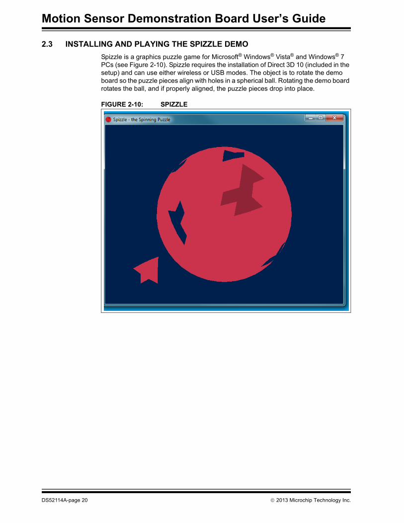
1. Locate the TeaPot Demo installer.exe file in your “Motion Sensor” installation directory and double-click to run the program.
You will see the TeaPot Installer Setup window (Figure 2-16). You can change the name of the installation directory, if necessary.
FIGURE 2-16: TeaPot INSTALLER SETUP
The TeaPot Demo will install the OpenGL drivers as well as Microchip USB drivers into C:\MCHPWinUSB.
2013 Microchip Technology Inc. DS52114A-page 25

Motion Sensor Demonstration Board User’s Guide
2. Run TeaPot.exe from the install directory. Align the demonstration board so that the red RF module end of the board is pointing towards the monitor. You should see the teapot.
FIGURE 2-17: EXAMPLE OF TEAPOT ORIENTATION
3. Rotate the demo board around the 3 axis to rotate the teapot. The PC OpenGL driver will render the teapot to show a fixed light source.
Note: The second raw data screen can be minimized if not needed.
4. If you are using the USB connection, the firmware will record your movements (for up to 15 minutes) and play them back using the on-board Flash memory (SST25VF016B). To start recording, press the power switch. To stop and play back the recorded movements, press the power switch a second time.
2.6 OBTAINING THE C SOURCE CODE FOR THE PIC24FJ256GB206
1. Go to the InvenSense Developers Corner (http://invensense.com/developers/).
2. First time users, complete the InvenSense Developer Registration.
An email will be sent with a temporary password. Login using the credentials in the email.
3. Once logged into the Developers Corner, click the Downloads tab.
4. For downloading, click on the “File” icon, read and accept the License Agreement.
5. Email us at [email protected] confirming that you clicked through the License Agreement and provide details regarding your login email address and name.
Once we verify that you have accepted the License Agreement, we will release the source code via our FTP site.
DS52114A-page 26 2013 Microchip Technology Inc.

Hardware Overview
2.7 REPROGRAMMING THE ZENA WIRELESS ADAPTER
The ZENA wireless adapter has been preprogrammed to work with the Motion Sensor Demonstration Board. If desired, the ZENA adapter can be programmed as a wireless sniffer and then reprogrammed with the Motion Sensor Demonstration Board code. In order to reprogram the ZENA adapter, Motion Sensor Demonstration Board, perform the following:
1. Open the WDS (Wireless Development Studio).
2. Select Tools and click ZENA Firmware Upgrade.
3. Select the ZENA Wireless Adapter, select the Hex file (found in the “Motion Sensor Demo Package” download, “Hex files” subdirectory), motionsensor-zena-chksum.hex, and click the Update button.
2.8 TROUBLESHOOTING
• Light not blinking on ZENA adapter – Wireless packets are not being received. Make sure that the Motion Sensor Demonstration Board is powered up and that the LED has two fast blinks, followed by a delay.
• Light not blinking correctly on Motion Sensor Demonstration Board – Two fast blinks indicate Wireless mode. USB mode is a single blink, once every 1.5 seconds.
2013 Microchip Technology Inc. DS52114A-page 27

Motion Sensor Demonstration Board User’s Guide
NOTES:
DS52114A-page 28 2013 Microchip Technology Inc.
MOTION SENSOR DEMONSTRATION
BOARD USER’S GUIDEAppendix A. Basics of Motion Sensing
A.1 OVERVIEW
For centuries, travelers have asked these two basic questions:
• Where am I?
• Where am I going?
We collectively call the answers to these questions, navigation. In today’s world, this is usually handled by GPS satellites, but in some cases, GPS alone is not reliable or cost effective. The alternative method, developed during the 1950’s, is called inertial measurement and this is what the Motion Sensor Demonstration Board is calculating for the supplied demo programs.
The initial application was for missile guidance systems. In order for a missile to be launched from Point A and travel 3,000 miles to Point B blindly (without receiving any information during the flight or using any sort of terrain mapping), it had to calculate the relative position of the launch point to the target point. Unlike a GPS system that tells you exactly where you are (and how high), an inertial system tells you the direction you are going (up/down/sideways) and how fast; where you are is always relative to where you started.
Recent advancements in MEMS (Micro-Electro-Mechanical Systems) technology have allowed smaller and less expensive sensing parts to fit on a low-cost PC board. The MEMS sensors used have three functions: an accelerometer, a gyroscope and a mag-netometer (compass). Temperature sensing is also used because MEMS devices are temperature-sensitive and compensation is applied in software.
MEMS motion sensors have a wide range of uses, from image stabilization to fitness monitoring, to many other consumer products. Motion sensing has become a “must have” for the tablet PC market. Motion sensing adds a modern, intuitive interface to provide rich user input. The low cost and ease of interfacing allow MEMS motion sensors to compete with mechanical switches in many applications. “Sensor Fusion” technology can be used to supply a 3-D reference frame which can be used directly by many applications.
The collection of sensors and the MPU (a PIC24FJ256BG206) form an IMU (Inertial Measurement Unit). IMUs are grouped by the number of independent sensor measure-ments, called ‘Degrees of Freedom (DOF)’. The DOF is based on 3-dimensional space that we all learned as X, Y and Z axes in geometry class. In general, X can be thought of as moving left/right, Y as moving forwards/backwards and Z as moving up/down. This would be called a 3DOF system.
On the Motion Sensor Demonstration Board, there is one part that has 6DOF (the InvenSense MPU-6050) and a 3DOF magnetometer (AKM8975). This creates a 9DOF IMU board.
2013 Microchip Technology Inc. DS52114A-page 29

Motion Sensor Demonstration Board User’s Guide
A.2 MEMS GYROSCOPE FUNCTION
The Motion Sensor Demonstration Board uses a silicon equivalent of a gyroscope inside the InvenSense MPU-6050. An angular rate gyroscope is a device that produces positive direction digital outputs for counterclockwise rotation around the 3 axis. The MPU-6050 measures the rate of change as the board is rotated. If the board is not moving (sitting on your desk, for example), the outputs would be zero for all 3 axes. If you were to rotate it around one axis, MPU-6050 would produce a digital value propor-tional to the angular acceleration around that axis. If you stop, the reading goes back to zero.
The angular acceleration can be integrated to find angular velocity and integrated again to determine position. Quantization error (from the A/D reading gyroscope), combined with errors from digital integration, will produce “drift” in the measurements.
A.3 MEMS ACCELEROMETER FUNCTION
The MPU-6050 contains a 3-axis accelerometer, which measures acceleration on the X, Y and Z axes. When the object is at rest, gravitational acceleration will be measured. If the object is dropped, measurements will be zero for all axes.
Data read from the accelerometer is not tied to rotational movements (like the gyroscope), but rather to the acceleration along any given axis.
A.4 SENSOR FUSION
The MPU-6050 uses a “Sensor Fusion” algorithm to take the 6-axis data input (3-axis gyroscope and 3-axis accelerometer) to generate a rotational reference frame for the object (as illustrated by the Spizzle and TeaPot demos). The rotational reference frame information is provided in the form of a 4-element Quaternion. The Quaternion data format provides computational and stability advantages over the use of Euler angles. The subject of “Quaternions” being used to represent rotational movements is covered well by Wikipedia.
A.5 MEMS MAGNETOMETER FUNCTION
The MEMS Magnetometer has not been implemented in software, but is connected via hardware for serial communication and limited development purposes. The MEMS Magnetometer measures the strength of the magnetic field along the X,Y and Z axes. Utilized in conjunction with a 9-axis sensor fusion algorithm, heading information can be computed.
DS52114A-page 30 2013 Microchip Technology Inc.

MOTION SENSOR DEMONSTRATION
BOARD USER’S GUIDEAppendix B. Schematic and Layout
FIGURE B-1: MOTION SENSOR DEMONSTRATION BOARD SCHEMATIC
GN
D1
GN
D12
2
WA
KE3
GN
D11
VIN
10
INT
4
SDI
5
SCK
6
NC
9
CS
8
SDO
7O
GN
DG
ND
WA
KE
GN
D
VIN
INT
SDI
SCK
NCCS
SD
U7
MIW
I_RESET
MIW
I_WA
KE
MIW
I_INT
MIW
I_DI
MIW
I_CLK
MIW
I_CS
MIW
I_DO
10 μF
C8
1 μF
C9
0.1 μF
C15
1 μF
C13
PIN 10
0.1 μF
C24
1 μF
C25
VD
D
PIN 19
MC
LR
10 μF
C14100 O
hm
R11
VBU
S
100K
R12
MIW
I_DO
MIW
I_RESET
CE
MIW
I_CS
DA
TAC
LOC
K
SDA
2SC
L2
12
J44.7K R7
4.7K R6
MIW
I_INT
DRD
Y
MIW
I_WA
KE
1K
R20LED
1Power LED
D+D-
GYRO
_INT
MIW
I_CLK
MIW
I_DI
45
Shield6
Sield
6
VBU
S1
D-
2
D+
3
VBU
S
D-
D+
J1
VBU
SD-
D+
123456
J2
MC
LR
DA
TA
CLO
CK
10K
R3
Programm
ing Header
CE
1
HO
LD7
Vss
4S
I5
SCK
6
SO2
WP
3
VD
D8
U6
SST25VF
016B-50-4C
-S2A
F
CE
MIW
I_DO
MIW
I_CLK
MIW
I_DI
1 μF
C26
GND2
VFB
4
VIN
6V
OU
T5
EN3
SW1
U3
BAT
+
10 μF
C16
10 μF
C17
BAT
+
Battery
953KR9887KR10
5.3 μH
L1
24LC
08BT-
I/OT
SCL
1
Vcc
4
Vss
2
SDA
3
WP
5U
9
SCL2
SDA
2
1 μF
C23
SCL
23
CPO
UT
20
VLO
GIC
8
FSYNC
11
NC16
SDA
24
RESV22
NC15
NC14
GND18
NC17
AU
X_C
L7
AD
O9
NC3
NC4
NC5
CLKIN1
NC2
RESV21
REGO
UT
10
SCL
CPO
UT
VLO
GIC
FSYNC
NC
SDA
RESV
NC
NC
GND
NC
AU
X_C
L
AD
O
NC
NC
NC
CLKIN
NC
RESVREG
OU
T
AUX_DA6
INT
12
VD D13
RESV
19
U1
MPU
-6050
SDA
SCL
10 nF
C22
GYRO
_INT0.1 μF
C21
0.1 μF
C20
10 nF
C19
SCL2
SDA
2
VSS15
SO6
CA
D1
11
VD D16
T ST 214
DRD
Y10
TST
69
NC
212
SDA /SI5
VID7
RSV
3
SCL/SK
4
TST1
1
CSB
2
C A D013
NC I8
VSSSO
CA
D1
VD D
T ST 2
DRD
Y
TST
6
NC
2
SDA /S// I
VID
RSV
SCL/SK
TST1
CSB
C A D0NC I
U8
AK8975P-L-RD
0.1 μF
C1
DRD
Y No Load
R1
0 Ohm R2
0.1 μF
C12
0 Ohm
R14SC
L2
0 Ohm
R16SD
A2
3VSEL
3VS
EL
PWR_
SW
EVQ
-PSL02K
21
S1PW
R_SW
100K
R18
Power Sw
itch
2.74M
R13
No Load
R4
0 Ohm R8
0.1 μF
C110.1 μF C2
VO
UT
5V
IN1
SH
DN
3
VSS
2
NC
4
U2
100K
R1910K
R5 D1
1 μF
C41 μF C3
0 Ohm
R21
PMD
5/C
N63
/RE51
SCL3/PM
D6/C
N64/RE6
2
SDA
3/PMD
7/CN
65/RE73
PMA
5/RP21/C1
IND
/CN
8/RG
64
RP26/P
MA
4/C1
INC
/CN
9/RG7
5
PMA
3/RP19/C2
IND
/CN
10/RG8
6
MC
LR7
RP27/P
MA
2/C2
INC
/CN
11/RG9
8
VSS
9
VD
D10
PGEC
3/AN
5/C1IN
A/V
BUS
ON/RP18
/CN
7/RB511
PGED
3/AN
4/C1IN
B/USBO
EN/RP28
/CN
6/RB412
AN
3/C
2INA
/VPIO
/CN
5/RB313
AN
2/C
2INB/V
MIO
/RP13/C
N4/RB2
14PG
EC1/A
N1/V
REF-/RP1/CN
3/RB115
PGED
1/AN0/V
REF+/P
MA
6/RP0/CN
2/RB016
PGEC
2/AN
6/RP6/CN
24/RB617
PGED
2/AN
7/RP7/RC
V/C
N25/RB7
18
AV
DD
19
AV
SS20
AN
8/RP8
/CN
26/RB8
21
AN
9/RP9
/PMA
7/CN
27/RB9
22
TM
S/C
VREF/A
N10
/PMA13/C
N28/RB10
23
TD
O/A
N11/PM
A12/C
N29/RB11
24
VSS
25
VD
D26
TCK/A
N12/C
TEDG
2/P
MA
11/CN
30/RB1227
TD
I/AN
13/CTED
G1/PM
A10/CN
31/RB1328
AN
14/CTPLS/RP14
/PMA
1/CN
32/RB1429
AN
15/RP29
/REFO/PM
A0/C
N12/RB15
30
PMA
9/RP10/SDA
2/CN
17/RF431
PMA
8/RP17/SCL
2/CN
18/RF532
RP16/U
SBID/C
N71/RF3
33
VBU
S /RF734
VU
SB
35
D-/RG
336
D+
/RG2
37
VD
D38
OS
CI/C
LKI/CN
23/RC
1239
OSC
O/C
LKO/C
N22
/RC15
40
VSS
41
RTCC
/DM
LN/RP2/C
N53/RD
842
DP
LN/S
DA
1/RP4/PM
A14/PM
CS1/C
N5
4/RD9
43
SCL1/RP3/PM
A15/PM
CS2/C
N55
/RD10
44
RP12/PM
AC
K2/C
N56
/RD11
45
DM
H/RP11/IN
T0/CN
49/RD
046
SOS
CI/C
3IND
/CN
1/RC13
47
SOSC
O/SC
LKI/T1CK/C
3INC
/RPI37/CN
0/RC14
48
VC
PCO
N/RP24/V
BUSC
HG/C
N50
/RD1
49
DP
H/RP23/P
MA
CK1/C
N51/RD
250
RP22/PM
BE0/CN
52/RD3
51
RP25/PM
WR/C
N13/RD
452
RP20/PM
RD/C
N14/RD
553
C3IN
B/CN
15/RD6
54
C3IN
A/SESSEN
D/C
N16
/RD7
55
VC
AP
56
ENV
REG57
VBU
SST/VC
MPS
T1/C
N6
8/RF058
VC
MPST2/C
N6
9/RF159
PMD
0/C
N58
/RE060
PMD
1/C
N59
/RE161
PMD
2/C
N60
/RE262
PMD
3/C
N61
/RE363
PMD
4/C
N62
/RE464
PA D0
U4
KXT
F9_INT
KXT
F9_INT
0.1 μF
C5
0.1 μF
C6
PIN 26
PIN 38
SCL
2K
R17
SDA
2K
R15
0.1 μF C7
1 μF
C10
DN
C2
IO V
DD
1
V DD5
SCL
9
SDA10
DN
C3
GN
D4
DN
C8
INT
7
DN
C6
U5
KXT
F9-106
TP
3T
P4
TP
5 TX
RX
RESET
VD
DV
DD
VD
D
VD
D
VD
DV
DD
VD
D
VD
D
VD
D
VD
D
VD
D
VD
DVD
DV
DD
VD
D
VD
DV
DD
VD
D
VD
DV
DD
VD
D
VD
D
VD
D
VD
D
VD
D
VD
D
VD
D
VD
D
VD
D
VD
D
VD
D
VD
D
VD
D
PIC24FJ256G
B206-I/M
R
MRF24J40M
A
MCP1802T-3302I/O
T
MCP1640T-I/C
HY
2013 Microchip Technology Inc. DS52114A-page 31
Motion Sensor Demonstration Board User’s Guide
NOTES:
DS52114A-page 32 2013 Microchip Technology Inc.

Schematic and Layout
NOTES:
2013 Microchip Technology Inc. DS52114A-page 33
DS52114A-page 34 2013 Microchip Technology Inc.
AMERICASCorporate Office2355 West Chandler Blvd.Chandler, AZ 85224-6199Tel: 480-792-7200 Fax: 480-792-7277Technical Support: http://www.microchip.com/supportWeb Address: www.microchip.com
AtlantaDuluth, GA Tel: 678-957-9614 Fax: 678-957-1455
BostonWestborough, MA Tel: 774-760-0087 Fax: 774-760-0088
ChicagoItasca, IL Tel: 630-285-0071 Fax: 630-285-0075
ClevelandIndependence, OH Tel: 216-447-0464 Fax: 216-447-0643
DallasAddison, TX Tel: 972-818-7423 Fax: 972-818-2924
DetroitFarmington Hills, MI Tel: 248-538-2250Fax: 248-538-2260
IndianapolisNoblesville, IN Tel: 317-773-8323Fax: 317-773-5453
Los AngelesMission Viejo, CA Tel: 949-462-9523 Fax: 949-462-9608
Santa ClaraSanta Clara, CA Tel: 408-961-6444Fax: 408-961-6445
TorontoMississauga, Ontario, CanadaTel: 905-673-0699 Fax: 905-673-6509
ASIA/PACIFICAsia Pacific OfficeSuites 3707-14, 37th FloorTower 6, The GatewayHarbour City, KowloonHong KongTel: 852-2401-1200Fax: 852-2401-3431
Australia - SydneyTel: 61-2-9868-6733Fax: 61-2-9868-6755
China - BeijingTel: 86-10-8569-7000 Fax: 86-10-8528-2104
China - ChengduTel: 86-28-8665-5511Fax: 86-28-8665-7889
China - ChongqingTel: 86-23-8980-9588Fax: 86-23-8980-9500
China - HangzhouTel: 86-571-2819-3187 Fax: 86-571-2819-3189
China - Hong Kong SARTel: 852-2943-5100 Fax: 852-2401-3431
China - NanjingTel: 86-25-8473-2460Fax: 86-25-8473-2470
China - QingdaoTel: 86-532-8502-7355Fax: 86-532-8502-7205
China - ShanghaiTel: 86-21-5407-5533 Fax: 86-21-5407-5066
China - ShenyangTel: 86-24-2334-2829Fax: 86-24-2334-2393
China - ShenzhenTel: 86-755-8864-2200 Fax: 86-755-8203-1760
China - WuhanTel: 86-27-5980-5300Fax: 86-27-5980-5118
China - XianTel: 86-29-8833-7252Fax: 86-29-8833-7256
China - XiamenTel: 86-592-2388138 Fax: 86-592-2388130
China - ZhuhaiTel: 86-756-3210040 Fax: 86-756-3210049
ASIA/PACIFICIndia - BangaloreTel: 91-80-3090-4444 Fax: 91-80-3090-4123
India - New DelhiTel: 91-11-4160-8631Fax: 91-11-4160-8632
India - PuneTel: 91-20-2566-1512Fax: 91-20-2566-1513
Japan - OsakaTel: 81-6-6152-7160 Fax: 81-6-6152-9310
Japan - TokyoTel: 81-3-6880- 3770 Fax: 81-3-6880-3771
Korea - DaeguTel: 82-53-744-4301Fax: 82-53-744-4302
Korea - SeoulTel: 82-2-554-7200Fax: 82-2-558-5932 or 82-2-558-5934
Malaysia - Kuala LumpurTel: 60-3-6201-9857Fax: 60-3-6201-9859
Malaysia - PenangTel: 60-4-227-8870Fax: 60-4-227-4068
Philippines - ManilaTel: 63-2-634-9065Fax: 63-2-634-9069
SingaporeTel: 65-6334-8870Fax: 65-6334-8850
Taiwan - Hsin ChuTel: 886-3-5778-366Fax: 886-3-5770-955
Taiwan - KaohsiungTel: 886-7-213-7828Fax: 886-7-330-9305
Taiwan - TaipeiTel: 886-2-2508-8600 Fax: 886-2-2508-0102
Thailand - BangkokTel: 66-2-694-1351Fax: 66-2-694-1350
EUROPEAustria - WelsTel: 43-7242-2244-39Fax: 43-7242-2244-393Denmark - CopenhagenTel: 45-4450-2828 Fax: 45-4485-2829
France - ParisTel: 33-1-69-53-63-20 Fax: 33-1-69-30-90-79
Germany - MunichTel: 49-89-627-144-0 Fax: 49-89-627-144-44
Italy - Milan Tel: 39-0331-742611 Fax: 39-0331-466781
Netherlands - DrunenTel: 31-416-690399 Fax: 31-416-690340
Spain - MadridTel: 34-91-708-08-90Fax: 34-91-708-08-91
UK - WokinghamTel: 44-118-921-5869Fax: 44-118-921-5820
Worldwide Sales and Service
11/29/12