MOS GB F 200P 3 kW 511052 - NIBE 200P consists of an electric boiler with cop-per lined water heater...
28
LEK 2 3 1 20 100 40 80 60 °C 0 120 T G R INSTALLATION AND MAINTENANCE INSTRUCTIONS FIGHTER 200P Immersion heater 3 kW MOS GB 0511-1 511052 FIGHTER 200P
Transcript of MOS GB F 200P 3 kW 511052 - NIBE 200P consists of an electric boiler with cop-per lined water heater...

LEK
2
3 1
20 100
40 8060°C
0 120TG
R
INSTALLATION AND MAINTENANCE INSTRUCTIONS
FIGHTER 200PImmersion heater 3 kW
MOS GB 0511-1 511052FIGHTER 200P

LE
K
Fighter 310PFighter 310P
LE
KFighter 310PFighter 310P
1
2
LE
K
Fighter 310PFighter 310P
LE
K
Fighter 310PFighter 310P
3
4
5

Contents 1
FIGHTER 200P
General information for the installerTransport and storage .......................................... 9Handling .............................................................. 9Installation ............................................................ 9Inspection of the installation ................................ 9Maximum boiler and radiator volumes ................ 9Hard water areas .................................................. 9
Pipe connectionsGeneral .............................................................. 10Tap water connection.......................................... 11Pump and pressure drop diagram ...................... 11
Ventilation connectionVentilation flow .................................................... 12Duct installation .................................................... 12Kitchen duct ........................................................ 12Adjustment .......................................................... 12Fan diagram ........................................................ 12
Electrical connectionsConnection .......................................................... 13Setting the fan capacity ........................................ 13Circulation pump control ...................................... 13Current, fuse ........................................................ 13Immersion heater .................................................. 13Connecting the room thermostat .......................... 14Mouting the room thermostat .............................. 14
Commissioning and adjustingPreparations ........................................................ 15Filling the heating system .................................... 15Venting the heating system .................................. 15Starting ................................................................ 16Setting the ventilation .......................................... 16Readjustment ...................................................... 16Draining the heating system ................................ 16Draining the water heater .................................... 16
Temperature levelsCompressor .......................................................... 17Periodical temperature increase .......................... 17Freezing protection and hot water prioritising ...... 17
ServiceOpening the cover on the distribution box ............ 18Refrigerant system .............................................. 18
Electrical circuit diagram Electrical circuit diagram ...................................... 19
Component locationsComponent locations .......................................... 20
List of componentsList of components .............................................. 21
Dimensions Dimensions and setting-out coordinates .............. 22Principle of dimensioning .................................... 22
Enclosed kitEnclosed kit .......................................................... 23Accessories .......................................................... 23
Technical specificationsTechnical specifications ...................................... 24
General Concise product description .................................. 2Setting table .......................................................... 2
System descriptionPrinciple of operation ............................................ 3System diagram .................................................... 3
Front panelFront panel functions .............................................. 4Automatic heating control system .......................... 4
Maintenance routinesCleaning the air filter ............................................ 5Cleaning the ventilation devices............................ 6Pressure gauge .................................................... 6Checking the safety valves .................................. 6
Dealing with malfunctionsLow temperature or lack of hot water .................... 7Low or lack of ventilation ........................................ 7Low room temperature .......................................... 7High room temperature .......................................... 7Switch position ”3” .................................................. 7Cleaning the fan ...................................................... 7Indications on the display ...................................... 8Resetting the pressostats ...................................... 8Helping the circulation pump to start ...................... 8
For the Installer
For Home Owners

General
FIGHTER 200P
For Home Owners
2
In order to get the ultimate benefit from your heat pump FIGHTER 200P you should readthrough the For Home Owners section in this Installation and Maintenance Instruction.
FIGHTER 200P is an exhaust air heat pump. This means it utilises energy in ventilation airand uses this energy for hot water and heating the house. A microprocessor ensures thatthe heat pump always works efficiently.
For the installation engineer: Please, hand over to the home owner this manual after finalised installation .
Installation date Flow water maximum temperaturenera
Installation engineersnera
Selected fan curve Circulation pump setting
To be filled in when the heat pump has been installed
If corresponding with NIBE, kindly state the serial number (103) of the FIGHTER 200P
089_ _ _ _ _ _ _ _ _ _ _
Maxiumum water supply pressure 16 bar
Operating pressure, tap water 6 bar
Expansion vessel, heating water, charge pressure 0,5 bar
Volume, water heater 170 litres
Maximum primary working pressure (heating side) 2,5 bar
Set opening pressure relief valve 6 bar
Set opening, temerature limiter, compressor 88 °C
Manufacter:NIBE ABBox 14 Järnvägsgatan 40285 21 MARKARYDSWEDEN
Immersion heater R50 / 3000W / 230 V
Expansion vessel, tap water, charge pressure 3,5 bar
Expansion valve, setting 3,5 bar
Mass, unit, filled with water 435 kg
Set opening pressure of temperature and pressure valve 7 bar
Set opening, temerature limiter, immersion heater 88 °C
Test results from following procedures:1-50-216 _______1-50-218 _______1-50-219 _______1-50-220 _______1-50-222 _______1-50-226 _______1-50-227 _______

FIGHTER 200P consists of an electric boiler with cop-per lined water heater and a heat pump that recoversenergy from ventilation air. The recovered energy issupplied to the heat pump. The heat pump must beinstalled in a ventilation system intended for mechani-cal exhaust air.The output of the immersion heater is 3,0 kW. Whenthe exhaust air at room temperature passes throughthe evaporator, the refrigerant evaporates because ofits low boiling point. In this way the heat in the air istransferred to the refrigerant.The refrigerant is then compressed in a compressor,causing the temperature to rise considerably.The warm refrigerant is led to the condenser. Here therefrigerant gives off its heat to the boiler water, so thatthe temperature of the the refrigerant drops and itsphases changes from gas to liquid. The refrigerantthen goes via a filter to the expansion valve, where thepressure drops and the temperature is lowered fur-ther.The refrigerant has now completed its circulation andreturns to the evaporator.
System description
FrånluftAvluft
3For Home Owners
Principle of operation
System diagram
FIGHTER 200P
Extract air Exhaust air
LEK
CWhen the room air haspassed through the heatpump it is discharged. Thetemperature of the air hasbeen significantly reducedas the heat pump hasextracted the energy in theroom air.
GThe air from the kitchenfan goes directly out intoa separate duct.
BThe warm roomair is fed toFIGHTER 200P
DFIGHTER 200P suppliesthe house with both hotwater and room heating.
EOutdoor air is drawn into the house.
AThe warm room air isdrawn into the air ductsystem.
FAir is transportedfrom rooms withoutdoor air devices torooms with exhaustair devices.

Front panel
FIGHTER 200P
For Home Owners
4
ThermometerHere the boiler temperature is indicated . Thevalue depends on the cut-out temperature ofthe immersion heater, the set value for thecompressor cut-out temperature and the hotwater taps.
A
C Indicators lampsTop lampLit Compressor is running.Flashing Alarming for tripped pressostates
or indicating standby mode(Compressor blocked).
Not lit Compressor is not running.
Midmost lampLit Defrosting is operational.Flashing Air filter to be cleaned.Not lit -
Lower lampLit Immersion heater is in operation.Flashing -Not lit Immersion heater is not in opera-
tion.
Front panel functions
D Switchwith 4 positions 0 - 1 - 2 - 3:
0 Heat pump off.
1 Fan is operational. Compressor andcirculation pump operational on demand.
2 Fan is operational. Compressor, immersionheater and circulation pump operational ondemand.
3 Standby mode. Fan is operational.Compressor is not operational. Immersionheater and circulation pump operational ondemand.
Pressure gauge Here the pressure of the radiator circuit isindicated . The scale marks go from 0 - 4 bars.Normal pressure is 0,5 - 1,5 bar.
B
E Hot water prioritising (hidden)with 3 positions Auto - On - Off:
Auto Hot water prioritising operational
On Hot water prioritising operational
Off Hot water prioritising not operational
F Circulation pump (hidden)with 2 positions Auto - On:
Auto The On and Off of the circulation pumpis controlled by the control system.
On Circulation pump permanently running
SwitchPressure gaugeThermometer Indicator lamps
Hot water priority (hidden) Circulation pump (hidden)
( )
20 100
40 8060°C
0 120TG
2
1 bar 3
0 4TG
A B C D
E F
The heat emission is controlled by means of a roomthermostat. On achieving the set temperature, the cir-culation pump inside FIGHTER 200P will stop.
Automatic heating control system

Maintenance routines 5For Home Owners
FIGHTER 200P
The heat pump air filter (63) should be cleaned regu-larly, about four times a year.
■ Set the switch (8) to “0”.
■ The upper service cover is opened by pulling thelower section outwards. The cover can then be lif-ted off.
■ Pull out the filter cassette (78).
■ Take out the filter and shake off any dirt. (Whenthe filter is very dirty, turn it upside-down andwash it carefully with water.)
Check that the filter is not damaged. New originalfilters can be ordered from NIBE.
■ Re-assembly takes place in the reverse order.
The cleaning time intervals vary depending on theamount of dust in the exhaust air. Each third month anindicator lamp (31) "Defrosting in progress/Check fil-ter" reminds about cleaning the air filter. Note that thetime will be set to zero by setting the switch to "0".
The heat pump and its ventilation ducting requiresome regular maintenance when the following pointsshould be checked.
The numbers in brackets refer to the section ”Compo-nent locations”.
Cleaning the air filter

LEK
2
3 1
20 100
40 8060°C
0 120TG
The pressure gauge reading should be between theinitial pressure of the expansion vessel (normally 0.5bar) and 1.5 bar (15 mvp). See Commissioning andadjusting.
Maintenance routinesFor Home Owners
6
FIGHTER 200P has three safety valves, one for theheating system and two for the water heater.
The heating system safety valve (52) must be com-pletely tight, but the hot water safety valve (47) mayrelease some water after hot water has been used.This is because the cold water which enters the waterheater to replace the hot water expands when heated,causing the pressure to rise and the safety valve toopen.
Safety valve (104) does not normally release water.
The safety valves must be checked regularly. Checkone valve at a time as follows:
■ Open the valve.
■ Check that water flows through the valve.
■ Close the valve.■ The heating system may need to be refilled after
checking the safety valve (52), see the section”Commissioning and adjustment” – ”Filling theheating system”.
The building’s ventilation devices should be cleanedregularly with a small brush to keep the correct venti-lation. The device settings must not be changed.
NOTE! If you take down more than one ventilationdevice for cleaning, do not mix them up.
Check that the ventilation opening (84), behind thelower front cover, is not blocked. Clean if necessary.
Cleaning the ventilation devices
Pressure gauge
FIGHTER 200P
Checking the safety valves
2
1 bar 3
0 4TG
LEK
2
3 1
20 100
40 8060°C
0 120TG
47
104
52

Dealing with malfunctions 7For Home Owners
FIGHTER 200P
When the switch is set to "3", the compressor is notoperational. The fan and the immersion heater areoperational. Normally the immersion heater lamp is litin mode "3", when the immersion heater is operatio-nal.
A possible fault on the printed circuit card can causethe disappearance of the number display. However,the immersion heater is still operational, if the ther-mostat has not cut-out the immersion heater.
Switch position ”3”
If the operating disturbance cannot be rectified by means of the above an installationengineer should be called. If necessary set the switch to ”3”.
■ Room thermostat setting not correct
High room temperature
■ Large amounts of hot water were used.
■ Circuit or main MCB tripped.
■ Possible earth circuit-breaker tripped.
■ Switch (8) set to “0”.
■ Temperature limiter (6) tripped. Contact service.
■ Wrong mode chosen on power switch (8).
■ Thermostat (3) for immersion heater set too low.
Low temperature or a lack ofhot water
■ Circuit or main MCB tripped.
■ RCD (if fitted) tripped.
■ Temperature limiter (6) tripped. Contact service.
■ Wrongly set room thermostat.
■ Circulation pump (16) stopped. See "Dealing withmalfunctions" – "Starting the pump".
■ Air in boiler or heating system.
■ Valves (44) and (50) in the radiator circuit closed.
■ Initial pressure in expansion vessel too low. Thiswill be indicated by low pressure on the pressuregauge (42). Contact the installer.
■ Thermostat (3) for immersion heater set too low.
■ Defrost mode - lamp flashing - see chapter "Lampindications".
■ Filter (63) clogged (possible replace).
■ Exhaust air device blocked or throttled down toomuch.
■ Circuit or main MCB tripped.
■ RCD (if fitted) tripped.
Low room temperature
Low or a lack of ventilation
In the event of malfunction or operating disturbances first check the points below:
NOTE! In all correspondence with NIBE
state the serial number089_ _ _ _ _ _ _ _ _ _ _
LEK
2
3 1
20 100
40 8060°C
0 120TG
The fan needs to be cleaned, if it is noisy. Call yourinstallation engineer.
Cleaning the fan
Dealing with malfunctions
FIGHTER 200P
For Home Owners
8
LEK
2
3 1
20 100
40 8060°C
0 120TG
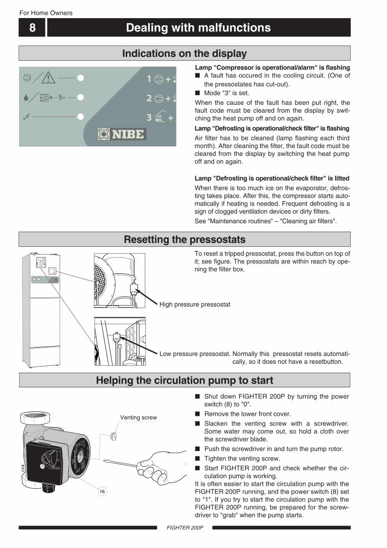
■ Shut down FIGHTER 200P by turning the powerswitch (8) to "0".
■ Remove the lower front cover.
■ Slacken the venting screw with a screwdriver.Some water may come out, so hold a cloth overthe screwdriver blade.
■ Push the screwdriver in and turn the pump rotor.
■ Tighten the venting screw.
■ Start FIGHTER 200P and check whether the cir-culation pump is working.
It is often easier to start the circulation pump with theFIGHTER 200P running, and the power switch (8) setto "1". If you try to start the circulation pump with theFIGHTER 200P running, be prepared for the screw-driver to "grab" when the pump starts.
Helping the circulation pump to start
Luftningsskruv
16
LE
K
GR
UN
DFO
SType
UP
S25 -
60
130
P/N
:59526447
230V
-
HE
JS
AN
PC
;0017N
IBD
K50H
z
IP 44
TF
110
Cla
ss H
Max. 1
0bar
2.5
uF
45
0.2
065
0.3
090
0.4
0
1m(A
)P,
(W)
To reset a tripped pressostat, press the button on top ofit; see figure. The pressostats are within reach by ope-ning the filter box.
High pressure pressostat
Low pressure pressostat. Normally this pressostat resets automati-cally, so it does not have a resetbutton.
Lamp "Compressor is operational/alarm" is flashing■ A fault has occured in the cooling circuit. (One of
the pressostates has cut-out).■ Mode "3" is set.
When the cause of the fault has been put right, thefault code must be cleared from the display by swit-ching the heat pump off and on again.
Lamp "Defrosting is operational/check filter" is flashingAir filter has to be cleaned (lamp flashing each thirdmonth). After cleaning the filter, the fault code must becleared from the display by switching the heat pumpoff and on again.
Lamp "Defrosting is operational/check filter" is littedWhen there is too much ice on the evaporator, defros-ting takes place. After this, the compressor starts auto-matically if heating is needed. Frequent defrosting is asign of clogged ventilation devices or dirty filters.
See "Maintenance routines" – "Cleaning air filters".
Indications on the display
Resetting the pressostats
Venting screw

General information for the installer 9For the Installer
FIGHTER 200P
Current regulations require the heating installation tobe inspected before it is commissioned. The inspec-tion must be carried out by a suitably qualified person.The above applies to installations with a closedexpansion vessel. A new inspection must be madewhen changing the heat pump or the expansion ves-sel.
The heat pump should preferably be erected with itsback about 10 mm from an outside wall in a utilityroom or similar, to minimise noise nuisance. If this isnot possible, avoid placing it against a wall behind abedroom or other room where noise may be a prob-lem. Irrespective of the placement the wall should besound insulated. NOTE! The distance between theheat pump and the wall should be at least 10 mm.
Route pipes so they are not fixed to an internal wallthat backs on to a bedroom or living room.
An area of approximately 15 cm is required on the leftside of the heat pump, at the temperature and pres-sure valve (104) to enable access to the valve.
NOTE! Since a waterfilled FIGHTER 200 weighsroughly 435 kilos, the floor must stand such a weight.
The heat pump should be transported and stored ver-tically in the dry.
The heat pump contains highly inflam-mable refrigerant. Special care shouldbe exercised during handling, installa-tion, service, cleaning and scrapping toavoid damage to the refrigerant systemand in doing so reduce the risk of leak-age.
Transport and storage
Handling
Installation
Normally it is no problem to install FIGHTER 200P inhard water areas since the maxing working tempera-ture is 60 °C.
Hard water areas
Inspection of the installation
The volume of the expansion vessel (85) is 12 litresand it is pressurised as standard to 0.5 bar (5 mwp).As a result, the maximum permitted height “H”between the vessel and the highest radiator is5 metres; see figure. If the standard initial pressure inthe pressure vessel is not high enough it can beincreased by adding air via the valve in the expansionvessel. The initial pressure of the expansion vesselmust be stated in the inspection document.
Any change in the initial pressure affects the ability ofthe expansion vessel to handle the expansion of thewater. The maximum system volume excluding theboiler is 106 litres at the above initial pressure.
Maximum boiler andradiator volumes
H

Pipe connections
FIGHTER 200P
For the Installer
10
Pipe installation must be carried out in accordance withcurrent norms and directives.
The system requires a low-temperature dimensioning ofthe radiator circuit. At DUT, the highest recommendedtemperatures are 55 °C on the flow line and 45 °C onthe return line.
When the circulation pump is running, the flow in theradiator circuit must not be completely stopped.
The total volume is 240 litres, with 170 litres in the waterheater and 70 litres in the boiler section.
The pressure vessel in the FIGHTER 200P is approvedfor max 9.0 bar (0.9 MPa) in the water heater and2.5 bar (0.25 MPa) in the double shell section.
Overflow water from the evaporator collection tray andsafety valves goes via non-pressurised collecting pipesto a drain so that hot water splashes cannot causeinjury. These non-pressurised collecting pipes shall notbe used for anything else. A discharge pipe from thetundish (108) connected to the expansion reliet valve(47) (safety valve) shall also be connected to a drain inthe same way.
Discharge pipes from tundishes shall have av verticalsection of pipe at least 300 mm long, before any elbowsor bends in the pipework. See following picture.
General
If the vertical distance, 300 mm, is hard to fulfil a heigh-tening console is available as an accessorie. No valveshould be fitted between the pressure reduction valve(expansion valve) and the storage cylinder.
500 mm maximum
300 mm minimum
Tundish
Metal discharge pipe fromtemperature relief value to tundish.
Metal discharge pipe from tundish,with continous fall.
Discharge belowfixed grating.
Fixed grating
Trapped gulley
Possible wall
Safety device(e.g. temperaturerelief valve).
<G3> / 4 22 mm 28 mm up to 9 m 1,0 m
G1 / 2 15 mm 35 mm up to 27 m 1,4 m
<G3> / 4 22 mm 42 mm up to 27 m 1,7 m
<G3> / 4 22 mm 35 mm up to 18 m 1,4 m
G1 28 mm 42 mm up to 18 m 1,7 m
G1 28 mm 35 mm up to 9 m 1,4 m
Valve Minimum size of Minimum size of discharge Maximum resistance allowed, Resistance createdoutlet size discharge pipe pipe from tundish expressed as a lenght by each elbow
of straight pipe or bend (i.e. no elbows or bends)
G1 28 mm 54 mm up to 27 m 2,3 m
G1 / 2 15 mm 28 mm up to 18 m 1,0 m
G1 / 2 15 mm 22 mm up to 9 m 0,8 m
Table sizing of copper discharge pipe for common temperature relief valve outlet sizes.

Pipe connections 11For the Installer
FIGHTER 200P
Pump and pressure drop diagram
Flöde
Till
gäng
ligt t
ryck
, kP
a
kPa
l/s
l/h
0 0,02700100 200 300 400 500 600
0,04 0,06 0,08 0,1 0,12 0,14 0,16 0,18 0,20
10
20
30
40
50
60
1
2
3
NOTE!The pipe work must be flushed
before the heat pump is connected,so that any contaminants do notdamage the components parts.
Hot and cold water are connected to pos (74) (hotwater) and (73) (cold water).
The attendant expansion vessel (107) must be con-nected to the hot water system.
Tap water connection
KV VV
Water heaterHeat pump
FIGHTER 200P
Cw Hw
Ava
ilabl
e pr
essu
re k
Pa
Flow l/h
The heat pump should be supplemented with an elec-tric water heater if a bubble pool or other significantconsumer of hot water is installed.

Ventilation connection
FIGHTER 200P
For the Installer
12
FIGHTER 200P is connected so that all ventilation airexcept the kitchen fan passes the evaporator (62) inthe heat pump. The lowest ventilation flow accordingto current standards is 0.35 l/s per m2 floor area. Foroptimum heat pump performance this ventilation flowshould not be less than 100 m3/h. (28 l/s).FIGHTER 200P is equipped with a ventilation openingin the base. As a result, an air flow of about 5 m3/h (1,4 l/s) is taken directly from the room where the heatpump is installed. Changing the ventilation capacity isdescribed under “Electrical connection - Setting thefan capacity”. See also “Circuit diagram”. The num-bering of the curves refers to the terminal block forfanspeed.
To obtain the necessary air exchange in every roomof the house, the exhaust air devices must be correct-ly positioned and adjusted. An incorrect ventilationinstallation may lead to reduced heat pump efficiencyand thus poorer operating economy, and may result indamage to the house.
NOTE!A duct in a masonry chimney stack
must not be used for extract air.
To prevent fan noise being transferred to the exhaust airdevices, it may be a good idea to install a silencer in theduct. This is especially important if there are exhaust airdevices in bedrooms. Because the heat pump containsa flammable refrigerant in the form of propane (R290),the air ducting system must be earthed. This is done bymaking a sound electrical connection to the exhaust airduct and extract air duct using the two earthing cablessupplied. The cables must then be connected to theearthing studs on top of the top cover. Duct connections should be made via flexible hoses,which must be installed so that they are easy to replace.The extract air duct is to be insulated using diffusion-proof material along its entire length. Provision must bemade for inspection of the duct. The exhaust air ductshould be fitted with an adjustment damper. Make surethat there are no reductions of cross-sectional area inthe form of creases, tight bends etc, since this willreduce the ventilation capacity. All joins in the ductingmust be sealed and pop-riveted to prevent leakage.The air duct system should, at a minimum, be of air tight-ness class B.
The diagram below shows the available ventilationcapacity.
Fan diagram
Ventilation flow Duct installation
Adjustment
The kitchen duct must not be connected to FIGHTER200P.
Kitchen duct
400
350
300
250
200
150
100
50
00 100 200 300 400
Luftflöde
Till
gän
glig
t st
atis
kt t
ryck
1 2 3 4 5 6 7 8 9 10
m3/h0 25 50 75 100 l/s
Pammvp
40
30
10
20
Airflow
mmwg Pa
Ava
ilabl
e st
atic
pre
ssur
e, P
a

Electrical connection 13For the Installer
FIGHTER 200P
Disconnect the heat pump before insulation testingthe house wiring.The supply (230 V~ 1-phase + N) for the heat pumpmust be connected to terminal (9) via a cable clamp.
The connection of the heat pump must be done underthe supervision of a qualified electrician.
The heat pump installation implies a contact breaker.
The vinyl-pipe on the right side may be used as cableentry conduit.The temperature limiter (6) cuts off the supply to theimmersion heater if the temperature rises to 88 °C; itcan be manually reset by pressing the button on thetemperature limiter. The temperature limiter (7) for the compressor cuts offthe supply to the compressor if the temperature risesto 88 °C; it can be manually reset by pressing the but-ton on the temperature limiter.
Connection
NOTE!Reset the temperature limiter,
it may have tripped during transport.
NOTE! The switch (8) must not be movedfrom �0� until the boiler has been
filled with water Otherwise thetemperature limiter, thermostat,
compressor and the immersion heatercan be damaged.
NOTE! The electrical installation, wiring andany service work must be done in strict
conformity to current regulationsunder the supervision of a qualified
electrician.
Setting the fan capacity
Normally a room thermostat is used controlling thestarts and stops of the circulation pump. When the setroom temperature is reached, the circulation pump isstopped and starts again when the temperature drops.For connection see diagram "Electrical connections" –"Connecting the room thermostat".
The circulation pump can even be operated manually.No room thermostat will be connected. Instead the cir-culation pump is operated by the switch (18) on thefront panel. The mode "Auto" does not permit anyoperation of the circulation pump if no room thermos-tat is connected. The switch in position "On" permitspermanent operation of the circulation pump.
Circulation pump control
The maximum current is 16,7 Ampere. Therefore a 20Ampere fuse shall be used. NOTE! Relevant electricalstandards must be considered.
Current, fuse
FIGHTER 200P is delivered with a 3 kW immersionheater (1). It is started and stopped via the micropro-essor card (34). If a failure occurs there is a tempera-ture limiter (6) (thermal cut-out) that is stopping theimmersion heater. An immersion heater without atemperature limiter is not allowed to be mounted.
Immersion heater
Selection of the exhaust fan capacity is done by con-necting the white conductor from the exhaust fan tothe required connection on the terminal (22). See dia-gram "Ventilation connection" – "Fan diagram". Theconnection No. 10 is set at factory.
Tap Voltage (V)1 1002 1103 1254 1405 1556 1707 1858 2009 21510 230
22
5 6 7 8 9 103 41 2
Svartwhite

Electrical connection
FIGHTER 200P
For the Installer
14
NL
L1N
(1)
(3)
(2)
The room thermostat (accessory) which must bedesigned for 230 V has to be connected on terminal(9) in position "Pil in" and "Pil ut". Position "N" on thesame terminal must be used, if the used thermostatrequires firm earthed neutral.
Make sure that the switch (18) is set to position "Auto".
A connection to earthed neutral is normally not requi-red, however, it will result in faster regulations.
Connecting the room thermostatRoom thermostat
(RT 10)9
Install the room thermostat in a neutral position wherethe set temperature is required. A suitable place is ona free inner wall in a hall approx. 1.5 m above thefloor. However, the sensor must not be preventedfrom measuring the correct indoor temperature, e.g.by placing in a niche, between shelves, behind a cur-tain, above or close to a heat source or the like. Alsoconsider any draughts from exterior doors. Neithermust the unit be affected by solar incident radiation.
Mounting the room thermostat
The numerals refer to the connection notation in theRT 10. Using another room thermostat the abovenumerals will not be valid.

Commissioning and adjusting 15For the Installer
FIGHTER 200P
■ The water heater is filled through the cold waterinlet (73). A hot water tap must be opened. Whenwater comes out of the hot water tap, the samemust be closed.
■ Open the filling valve (49) to fill the boiler and theradiator system.
■ After a while the pressure gauge (42) will showrising pressure. When the pressure has reachedabout 2.5 bar a mix of air and water starts to emer-ge from the safety valve (52). Close the filling valve(49).
■ Open the safety valve (52) until the pressure in theheating system comes to normal working range(0,5 – 1,5 bar).
■ If there exists the risk that frost might burst thepipes, anti-freeze must be added to the water ofthe heating system. (At a maximum 50 % glycol).
■ Vent the electric boiler through the safety valve(52) and the rest of the heating system through therelevant venting valves.
■ Keep topping up and venting until all air has beenremoved and the pressure is correct.
Filling the heating system
Venting the heating system
Check that the switch (8) is set to “0”.
Check that valves (44) and (50) are fully open andthat the temperature limiter (6) has not tripped (pressfirmly the knob). FIGHTER 200P is supplied with alimiting valve (5) mounted on the outlet pipe. This oneallows to set a maximum outlet temperature in orderto protect the floor in an existing floor heating system.This valve is adjustable between 38 and 55 °C. Theex works setting is 38 °C. Turn setting knob (19)clockwise to lower the temperature
and counter-clockwise to lower the same until desiredsetting is reached. A quarter turn is equal to 5 °C.
Preparations
LEK
ter-ledningradiatorer
16
44
5
19
108
52
99
k.v.v.v.
355180507974 47
k.v.v.v.Blaha blaha
och annattrams
ter-ledningradiatorer
Blaha blahaoch annat
trams
4973
95
Hw. Cw.

Commissioning and adjusting
FIGHTER 200P
For the Installer
16
This is how to drain the water heater:
■ Disconnect the overflow pipe from the drain con-nection (79) and connect a hose to a drainingpump instead. Where no draining pump is availa-ble, the water can be released into the overflowfunnel (99).
■ Open the drain valve (47).
■ Open a hot water tap to let air into the system. Ifthis is not enough, undo the pipe coupling (74) onthe hot water side and pull out the pipe.
During the initial running period, air is given off by the
heating water, and venting can be necessary. If bubb-ling sounds can be heard from the heat pump, theentire system requires further venting. NOTE! Thesafety valve (52) also acts as a manual venting
valve. Operate it with care, since it opens quickly.
The hot water can be drained off through the drainvalve (51) using an R15 (1/2") hose coupling. Removethe cover (80) from the valve (51). Screw on the hosecoupling and open the valve (51). Open the safety val-ve (52) to let air into the system.
Draining the heating system
Readjustment
Draining the water heater■ Set the switch (8) to "2" in order to accelerate the-
heating of the radiator system. NOTE! The com-pressor has a start delay of about 10 minutes in thestart mode.
■ Set the designed capacity on the circulation pumpusing its switch (35). See the section "Pipe con-nections” – ”Pump and pressure drop diagram".Make sure that the switch is not in an intermediateposition.
Starting
Ventilation flows and fan transformer settings aregiven on the ventilation drawings.
■ Selection of the exhaust fan capacity is done byconnecting the white conductor from the exhaust fanto the required connection on the terminal (22). Seediagram "Ventilation connection" – "Fan diagram". Toensure the lowest possible noise level, set the fan forthe lowest possible capacity.
■ Make sure that all outside air devices are fullyopen.
■ Set correct ventilation flows on the indoor exhaustair devices.
Setting the ventilation

( )
Auto
1
2
3 120 100
40 8060C
0 120TG
2
1 bar 3
0 4TG
Temperature levels 17For the Installer
FIGHTER 200P
On delivery the compressor has a set working levelsignifying the compressor to start when the temperatu-re drops at the compressor sensor (94) to 50° C and tostop when the temperature arrives at 53° C. It is possi-ble to increase these temperatures by two degrees (52and 55° C respectively) in oder to achieve a somewhathigher hot water temperature with the power switch in
mode "1" (immersion heater not operational). This canbe done by changing the mode of the switch for No 1on the microprocessor board (34) to mode "On".However, be aware that this means somewhat adver-se working conditions for the compressor, as thiseffects the economies slightly negative.
Compressor
FIGHTER 200p is equipped with the function for perio-dical temperature increase. This means that the tem-perature will be put up to 60° C at regular intervals.This function is not set functional at factory. How-ever,this function will become operational, if the switchNo 4 on the printed circuit card will be changed tomode "On" and if the hot water priority is operational.This setting allows a hot water increase once a week.Once a day will be operational, if the switch No. 3 willbe set in the mode "On". Note that while this heating isoperational, the circulation pump is not operationaland the main part of the heating is done by only
immersion heater, which effects the economies slight-ly negative. Also note that while this heating theimmersion heater is operational, although the powerswitch is set to "1".
Periodical temperature increase
NOTE!Periodical temperature increase is
possible only if the hot waterprioritising is operational.
If permanent operation of the circulation pump is desi-red, FIGHTER 200P is even equipped with a switch(18) to alter between permanent and automatic opera-tion, that is when the control system decides if the cir-culation pump has to be operational or not. See dia-gram "Electrical connections" -"Circulation pump con-trol".NOTE! If permanent operation is chosen, the hotwater prioritising is not operational as desired. Theperiodical temperature increase should not bemade active.
FIGHTER 200P is equipped with a three-mode-switch(25) in order to choose proper hot water operation, so-called hot water prioritising.The following three modes are available:Off This means that the hot water prioritising is not
operational.On Hot water prioritising is operational.Auto Not used. Same function as mode ”On”.
Freezing protection and hot water prioritising
LEK
34
If hot water prioritising is operational all energy fromthe compressor and the immersion heater (if mode "2"is chosen on power switch) is used to heat up the hotwater. This happens normally when the temperatureat the immersion heater sensor (88) drops to 48° C.The circulation pump will start again when the tempe-rature attains 51° C. These temperatures can be drop-ped by two degrees (that is 46 and 49° C respectively)in order to retarder the prioritising slightly. This is doneby changing switch No 2 on the printed circuit card(34) to mode "On".
1825

Service
FIGHTER 200P
For the Installer
18
LE
K34
57
22
54
28
To lower the front panel, unscrew the two screws atthe top of the panel.The panel can then be lowered to
the horizontal position (where it rests on stops on eit-her side of the front panel).
Work on the refrigerant system must bedone by authorised personnel in accor-dance with the relevant legislation onrefrigerants, supplemented by additionalrequirements for flammable gas, forexample, product knowledge as well asservice instruction on gas systems withflammable gases.
Opening the cover on the distribution box
Refrigerant system

Electrical circuit diagram 19For the Installer
FIGHTER 200P
T
T
9
86
25
15
34
94
88
8
3
6
54
1
16
11
18
57
20
36
NL L1 N
PP
2726
28
4133
T
8282
13
Bro
wn
Blu
e
Bla
ck
C
R
S
21 53 4 6
Läge 0
Läge 1
Läge 2
Läge 3
AC/DC
230 V 12 V
Relä 3
Relä 1
Relä 2
69
22
T
7
12
11
10
9
8
7
6
5
4
3
2
1
Mode 0
Mode 1
Mode 2
Mode 3

For the Installer
Components locations20
FIGHTER 200P
LEK
( )
Auto
1
2
3 120 100
40 8060C
0 120TG
2
1 bar 3
0 4TG
ter-ledningradiatorer
8
31 32
94
86
30
Fram-ledning
radiatorer
9
3
6
11
18
59
16
17
44
70
5
19
78
27
36
33
58
108
52
96
109
97
42
62
48
63
87
65
99
ter-ledning
radiatorer
k.v.v.v.
41
35518071507974 47
84
98
85
43
53
1
k.v.v.v.Blaha blaha
och annattrams
ter-ledningradiatorer
Blaha blahaoch annat
trams
10366 49
88
25
104
10573
95
Radiatorsystemoutlet
Radiatorsystem inlet
Hw. Cw.

List of componentsFor the Installer
21
FIGHTER 200P
1 Immersion heater - 3,0 kW3 Thermostat for immersion heater5 Limiting valve, heating system6 Temperature limiter7 Temperature limiter, compressor8 Power switch with mode 0 - 1 - 2 - 39 Feeding terminal and room thermostat
16 Circulation pump17 Circulation pump vent screw18 Pushbutton switch for circulation pump19 Setting knob for limiting valve20 Exhaust air ventilation device22 Connection terminal for fan capacity25 Pushbutton switch for hot water prioritising26 Motor protection device for compressor27 Compressor28 Working capacitor for compressor30 Indicator lamp "Compressor running/alarm"31 Indicator lamp "Defrosting on/check filter"32 Indicator lamp "Immersion heater on"33 High pressure pressostat34 Microprocessor card with power pack35 Capacity setting for circulation pump
36 Exhaust air fan41 Low pressure pressostat42 Boiler pressure gauge43 Boiler thermometer44 Shutoff valve for circulation pump & heating
system outlet47 Safety valve for water heater48 Expansion valve49 Combined filling & non return valve for heating
system50 Shutoff valve for heating system inlet (return)51 Drain valve for heating system52 Safety valve for heating system53 Vacuum valve (hidden)54 Fan transformer 57 Working capacitor for exhaust air fan58 Tension load stop for feeding conductor59 Tension load stop for room thermostat conductor62 Evaporator63 Air filter65 Filter drier66 Type plate69 Compressor heater
Connection Setting-out dimensionsA B C
70 Flow line for heating system ............................................. Compression ring Ø 22 mm 100 ... 465 ...... 9071 Return line for heating system ......................................... Compression ring Ø 22 mm 130 ... 465 ...... 19073 Cold water inlet ................................................................ Compression ring Ø 22 mm 180 . 465 ...... 29074 Hot water outlet from water heater ................................... Compression ring Ø 22 mm 295 ... 465 ...... 34577 Side access panel to valve connections78 Filter box (hidden)79 Drain & overflow connection from water heater80 Drain connection from heating system ............................. R 15 utv82 Room thermostat (accessory)84 Ventilation opening85 Expansion vessel86 Temperature sensor from evaporator88 Temperature sensor from immersion heater & hot water prioritising90 Ventilation connection for exhaust air .............................. Ø 125 mm ..................... 2095 ...... 295 ...... 16091 Ventilation connection for vented air ................................ Ø 125 mm ..................... 2095 ...... 295 ...... 48594 Temperature sensor for working compressor95 Overflow pipe from water heater safety valve96 Overflow pipe from heating system safety valve97 Condensate drain from fan box98 Overflow water discharge ................................................. PVC-pipe, 32 mm outer diameter99 Collecting funnel for overflow water
103 Serial No. plate104 Temperature and pressure valve105 Pressure reduction valve107 Expansion vessel, tap water108 Tundish from safety valve109 Tundish from pressure valve

Dimensions
FIGHTER 200P
For the Installer
22
Dimensions and setting-out coordinates
Undvik rördragning inom streckmarkeratområde för att underlätta service
Skyddsklenspänning Ø 16
Frånluft Ø 125Avluft Ø 125
Elektriskmatning Ø 25
Dockning Ø 16
91 90
A15
Stä
llbar
15
– 40
250
45
Min avstånd10 mm från vägg
Lucka på båda sidor
Erforderligt utrymme för demontering av övre frontlucka
77
B615
115
C 355
600
2095
440115
295
70
35
40 20
35
70
A, B and C: see "Connection" in "Component list".Pipes must not be run from the floor in the areaindicated by dots.
A clear space of 500 mm isneeded in front of the heatpump for servicing.
Principle of dimensioning
Klämring Cu-rör
Space required for removal ofupper front access panel
Minimum distancefrom wall 10 mm
Safety low voltage ø 16
Electrical feeding ø 25
Docking ø 16
Exhaust air ø 125 Vented air ø 125
Compression ring Copper pipe
Access panel onboth sides
When running pipes in the hatched areato facilitate servicing.
Adj
usta
ble
15-4
0

Enclosed kit 23For the Installer
FIGHTER 200P
Accessories
Expansion vessel, tap water (is delivered separately)
LEK
107
Room thermostat RT 10Part no 418 366
LEK
10
15 20
2530°C
LEK
Heightening consoleHeight: 125 mmPart no 089195

Technical specifications
FIGHTER 200P
24
Exhaust air fan power rating 170 W
Required ceiling height 2 185 mm
Depth 615 mm
Total volume 240 liter
Water heater volume 170 liter
Supply voltage 230 V~ 1-phase + N
Immersion heater power rating 3,0 kW
Protection IP 21
Maximum pressure in double jacket vessel 0,25 MPa (2,5 bar)
Refrigerant quantity 420 g
Cut-in temperature for compressor 50 °C * (Controlled by a separate sensor)
Cut-in temperature for immersion heater 49 °C *
Setting area for the limiting valve 38 – 55 °C
Cut-out temperature, temperature limiter for immersion heater 88 °C
Sound power level** 46 – 50 dB(A)
Break pressure for high pressure pressostat 2,45 MPa (24,5 bar)
Break pressure for low pressure pressostat 0,15 MPa (1,5 bar)
Height (excl. feet 15-40mm) 2 095 mm
Width 600 mm
Net weight 195 kg
Volume in double jacket 70 liter
Expansion vessel volume, tap water 18 liter
Max operating current 16,7 A
Circulation pump power rating 100 W
Compressor power rating 550 W
Maximum pressure in water heater 0,9 MPa (9 bar)
Design pressure in double jacket volume 0,25 MPa (2,5 bar)
Refrigerant type R290 (propane)
Cut-out temperature for compressor 53 °C *
Cut-out temperature for immersion heater 52 °C *
Cut-out temperature, termostat for immersion heater 70 °C
Cut-out temperature, temperature limiter for compressor 88 °C
Sound level in room where installed*** 42 – 46 dB(A)
* Concerns settings on delivery
** A-weighted sound power level (LWA). The value varies with the selected fan curve.
*** A-weighted sound pressure level (LpA). The value varies with the damping capacity of the room.These values apply with a damping of 4 dB.
Expansion vessel volume, heating system 12 liter
IP 21
For the Installer


NIBE ABSWEDEN
R
Tel: +46 - (0)433 - 73 000Fax: +46 - (0)433 - 73 190E-mail: [email protected]
Box 14Järnvägsgatan 40SE-285 21 MARKARYD

![INVITATION_TO_LOVE_2005 200p 21.1.2011[1]](https://static.fdocuments.in/doc/165x107/577d2ecb1a28ab4e1eb00199/invitationtolove2005-200p-21120111.jpg)