Molecular Dynamics Simulations of Gas Selectivity in Amor ...
13
Molecular Dynamics Simulations of Gas Selectivity in Amor- phous Porous Molecular Solids Shan Jiang, ǂ Kim E. Jelfs, ǂ Daniel Holden, ǂ Tom Hasell, ǂ Samantha Y. Chong, ǂ Maciej Haranczyk, † Abbie Trewin ǂ and An- drew I. Cooper ǂ * ǂ Department of Chemistry and Centre for Materials Discovery, University of Liverpool, Crown St., Liverpool L69 7ZD, UK † Computational Research Division, Lawrence Berkeley National Laboratory, One Cyclotron Road, Mail Stop 50F-1650, Berkeley, CA 94720-8139, USA KEYWORDS Porous organic cages; crystalline; amorphous; microporous; gas diffusion; molecular dynamics. ABSTRACT: Some organic cage molecules have structures with protected, internal pore volume that cannot be in-filled, irrespective of the solid-state packing mode: that is, they are intrinsically porous. Amorphous packings can give higher pore volumes than crystalline packings for these materials, but the precise nature of this additional porosity is hard to under- stand for disordered solids that cannot be characterized by X-ray diffraction. We describe here a computational methodolo- gy for generating structural models of amorphous porous organic cages that are consistent with experimental data. Molecu- lar dynamics simulations rationalize the observed gas selectivity in these amorphous solids, and lead to insights regarding self-diffusivities, gas diffusion trajectories, and gas hopping mechanisms. These methods might be suitable for the de novo design of new amorphous porous solids for specific applications, where 'rigid host' approximations are not applicable. 1.Introduction Molecular selectivity is central to many applications of nanoporous solids, 1-3 and this is determined by the size and shape of the pores, and interactions with the pore sur- faces. 4 Control over pore structure is therefore desirable, so that predictive structure-property relationships can be established. In recent years, crystalline porous solids, such as zeolites and metal-organic frameworks (MOFs), 3 have played a dominant role here. These ordered structures have uniform pore sizes that can be characterized at the molecular level using techniques such as X-ray diffraction. Hence, a range of computational techniques have been developed to provide a rational, molecular-level design basis for crystalline porous solids for separations. 5-9 By contrast, there are fewer computational approaches to underpin the molecular design of amorphous porous sol- ids, despite their possible practical advantages. For exam- ple, amorphous porous polymers can form robust, solu- tion-processable separation membranes. 10 Recently, porous molecular solids, 11-13 where packing is dictated by weak van der Waals forces rather than extend- ed bonding, has attracted attention. Unlike extended net- works, ‘porous molecules’ can be soluble in organic sol- vents and have been solution processed into nanoparti- cles 14 as well as porous composites 15 and molecular sen- sors. 16 So far, most porous molecular solids, other than nanoporous polymers, 10 have been crystalline. However, amorphous porous molecular solids 17-20 can have practical advantages. For example, some organic cage molecules are much more porous when rendered amorphous than they are in their crystalline forms. 14 We rationalized this on the basis of additional, extrinsic porosity between the cage molecules that is not present in the crystalline state. It is possible to process organic cage molecules into amor- phous solids from solution: for example, by freeze- drying. 14 Amorphous porous molecular solids can also be created by chemical synthesis – for example, by synthesiz- ing ‘scrambled’ organic cages comprising a mixture of mol- ecules with different shapes that cannot therefore crystal- lize, irrespective of how the solvent is removed. 14,20 How- ever, the purposeful molecular design of such materials is challenging because, unlike crystalline porous solids, func- tions such as sorption selectivity cannot simply be corre- lated with a crystal structure. Hence, there is a need to develop underpinning computational methods for the mo- lecular level understanding of porosity in amorphous mo- lecular solids. 21 A primary challenge in simulations for amorphous solids is to generate physically representative models. This is more difficult than for ordered materials where crystal structures are known. For amorphous polymers, a com- mon approach is to pack polymer chains at either an artifi- cially low density or to an observed experimental density, and subsequently to follow several compression and relax- ation steps using molecular dynamics (MD) simulations until the target experimental density is achieved. 22-26 How- ever, some drawbacks exist for these methods. Most signif- icantly, the simulations rely on an experimental target density. This can be challenging to determine accurately for microporous solids and the density is, of course, un- known for new, hypothetical molecular designs. In some cases, matching to an experimental target density might lead to oversimplifications because inhomogenieties in the solid, for example, large voids, cannot be represented in a small simulation cell while still matching the bulk experi-
Transcript of Molecular Dynamics Simulations of Gas Selectivity in Amor ...

Molecular Dynamics Simulations of Gas Selectivity in Amor-phous Porous Molecular Solids
Shan Jiang,ǂ Kim E. Jelfs,ǂ Daniel Holden,ǂ Tom Hasell,ǂ Samantha Y. Chong,ǂ Maciej Haranczyk,† Abbie Trewinǂ and An-drew I. Cooperǂ*
ǂDepartment of Chemistry and Centre for Materials Discovery, University of Liverpool, Crown St., Liverpool L69 7ZD, UK
†Computational Research Division, Lawrence Berkeley National Laboratory, One Cyclotron Road, Mail Stop 50F-1650, Berkeley, CA 94720-8139, USA
KEYWORDS Porous organic cages; crystalline; amorphous; microporous; gas diffusion; molecular dynamics.
ABSTRACT: Some organic cage molecules have structures with protected, internal pore volume that cannot be in-filled, irrespective of the solid-state packing mode: that is, they are intrinsically porous. Amorphous packings can give higher pore volumes than crystalline packings for these materials, but the precise nature of this additional porosity is hard to under-stand for disordered solids that cannot be characterized by X-ray diffraction. We describe here a computational methodolo-gy for generating structural models of amorphous porous organic cages that are consistent with experimental data. Molecu-lar dynamics simulations rationalize the observed gas selectivity in these amorphous solids, and lead to insights regarding self-diffusivities, gas diffusion trajectories, and gas hopping mechanisms. These methods might be suitable for the de novo design of new amorphous porous solids for specific applications, where 'rigid host' approximations are not applicable.
1.Introduction
Molecular selectivity is central to many applications of nanoporous solids,1-3 and this is determined by the size and shape of the pores, and interactions with the pore sur-faces.4 Control over pore structure is therefore desirable, so that predictive structure-property relationships can be established. In recent years, crystalline porous solids, such as zeolites and metal-organic frameworks (MOFs),3 have played a dominant role here. These ordered structures have uniform pore sizes that can be characterized at the molecular level using techniques such as X-ray diffraction. Hence, a range of computational techniques have been developed to provide a rational, molecular-level design basis for crystalline porous solids for separations.5-9 By contrast, there are fewer computational approaches to underpin the molecular design of amorphous porous sol-ids, despite their possible practical advantages. For exam-ple, amorphous porous polymers can form robust, solu-tion-processable separation membranes.10
Recently, porous molecular solids,11-13 where packing is dictated by weak van der Waals forces rather than extend-ed bonding, has attracted attention. Unlike extended net-works, ‘porous molecules’ can be soluble in organic sol-vents and have been solution processed into nanoparti-cles14 as well as porous composites15 and molecular sen-sors.16 So far, most porous molecular solids, other than nanoporous polymers,10 have been crystalline. However, amorphous porous molecular solids17-20 can have practical advantages. For example, some organic cage molecules are much more porous when rendered amorphous than they are in their crystalline forms.14 We rationalized this on the basis of additional, extrinsic porosity between the cage
molecules that is not present in the crystalline state. It is possible to process organic cage molecules into amor-phous solids from solution: for example, by freeze-drying.14 Amorphous porous molecular solids can also be created by chemical synthesis – for example, by synthesiz-ing ‘scrambled’ organic cages comprising a mixture of mol-ecules with different shapes that cannot therefore crystal-lize, irrespective of how the solvent is removed.14,20 How-ever, the purposeful molecular design of such materials is challenging because, unlike crystalline porous solids, func-tions such as sorption selectivity cannot simply be corre-lated with a crystal structure. Hence, there is a need to develop underpinning computational methods for the mo-lecular level understanding of porosity in amorphous mo-lecular solids.21
A primary challenge in simulations for amorphous solids is to generate physically representative models. This is more difficult than for ordered materials where crystal structures are known. For amorphous polymers, a com-mon approach is to pack polymer chains at either an artifi-cially low density or to an observed experimental density, and subsequently to follow several compression and relax-ation steps using molecular dynamics (MD) simulations until the target experimental density is achieved.22-26 How-ever, some drawbacks exist for these methods. Most signif-icantly, the simulations rely on an experimental target density. This can be challenging to determine accurately for microporous solids and the density is, of course, un-known for new, hypothetical molecular designs. In some cases, matching to an experimental target density might lead to oversimplifications because inhomogenieties in the solid, for example, large voids, cannot be represented in a small simulation cell while still matching the bulk experi-
mental density. Hence, poor estimation of physical proper-ties might arise.24,27 Also, these procedures sometimes fail to build a realistic structure due to atomic overlaps of large, rigid repeat units.25 Nonetheless, a number of com-putational studies exist for amorphous porous organic polymers, such as polymers of intrinsic microporosity (PIMs),10 hypercrosslinked polymers (HCPs),28-30 and con-jugated microporous polymers.31 Of particular note, Colina and co-workers reported a simulation scheme for generat-ing models for HCPs that followed the synthetic polycon-densation route for these materials.30,32 The final step in structure generation was followed by a 21-step compres-sion and slow decompression protocol that resulted in densities that were close to those from experiments. Signif-icantly, physical properties such as density and pore vol-ume emerged from the simulation, rather than being input from experiment. The same approach was used to generate structural models for amorphous PIM materials33,34 and structurally-related amorphous porous organic molecules.35 In this latter work, the molecules were packed at either a specified final density or at a low density, and a MD compression/relaxation scheme or annealing proce-dure was applied.35 Structural analysis was carried out by comparison of simulated and experimental densities, sur-face areas, pore volumes and wide-angle X-ray scattering (WAXS). It was observed that different simulation methods had a significant effect on the structural models. Packing molecules at a low initial density and then performing a 21-step MD simulation was proposed as the best simula-tion methodology for these systems, since it was again not necessary to predetermine a target density. These simula-tions both rationalize known materials and suggest ap-proaches to design new, improved molecules: for example, suggesting that more rigid structures and bulkier function-al end groups might enhance microporosity. A follow-up study by Siperstein and co-workers involves the calcula-tion of surface areas, free volumes, and argon adsorption isotherms.36
A large number of computational studies have focused on gas diffusivities in amorphous polymers,22,27,37,38 not least because of the relevance of such phenomena in gas membrane separations. A hopping mechanism has been suggested for gas diffusion, whereby gas molecules jump from one cavity to another as a result of transient channels appearing between these cavities during dynamic mo-tions.39,40 A relatively small number of simulation studies have focused on gas diffusion in porous molecular solids, as opposed to polymers, and these relate to crystalline rather than amorphous organic solids. For example, stud-ies have investigated guest inclusion and diffusion in crys-talline cucurbit[n]uril and calixarenes.41-44 In terms of crys-talline organic cages, we have used MD simulations to ra-tionalize H2/N2 gas selectivity for a crystalline porous cage, CC1β,45 and the molecular selectivity of crystalline CC3-R towards various C8 and C9 aromatic isomers.46 To date, however, there are no studies to our knowledge on MD of guest diffusion in porous amorphous molecular solids.
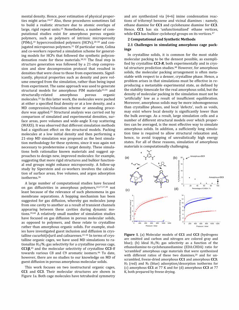
This work focuses on two isostructural organic cages, CC1 and CC3. Their molecular structures are shown in Figure 1a. Both cage molecules have tetrahedral symmetry
and are synthesized via [4+6] imine condensation reac-tions of triformyl benzene and vicinal diamines : namely, ethane diamine for CC1 and cyclohexane diamine for CC3. Hence, CC1 has six ‘unfunctionalized’ ethane vertices, while CC3 has bulkier cyclohexyl groups on its vertices.47
2 Computational and Synthetic Methods
2.1 Challenges in simulating amorphous cage pack-ings
In crystalline solids, it is common for the most stable molecular packing to be the densest possible, as exempli-fied by crystalline CC3-R, both experimentally and in crys-tal structure prediction studies.48 However, for amorphous solids, the molecular packing arrangement is often meta-stable with respect to a denser, crystalline phase. Hence, a problem arises in that simulations must be effective in re-producing a metastable experimental state, as defined by the stability timescale for the real amorphous solid, but the density of molecular packing in the simulation must not be ‘artificially’ low as a result of insufficient equilibration. Moreover, amorphous solids may be more inhomogeneous than crystalline phases, and local ‘defects’, such as voids, may exist where local density is significantly lower than the bulk average. As a result, large simulation cells and a number of different structural models over which proper-ties can be averaged, is the most effective way to simulate amorphous solids. In addition, a sufficiently long simula-tion time is required to allow structural relaxation and, hence, to avoid trapping of unrealistically high energy states. For all of these reasons, simulation of amorphous materials is computationally challenging.
Figure 1. (a) Molecular models of CC1 and CC3 (hydrogens are omitted and carbon and nitrogen are colored gray and blue); (b) Ideal H2/N2 gas selectivity as a function of the ethanediamine-to-cyclohexanediamine (EDA:CHDA) ratio for ‘scrambled’ amorphous cage materials that were synthesized with different ratios of these two diamines,20 and for un-scrambled, freeze-dried amorphous CC1 and amorphous CC3; H2 (red) and N2 (blue) adsorption/desorption isotherms for (c) amorphous CC1 at 77 K and for (d) amorphous CC3 at 77 K, both prepared by freeze drying.
(a) (b)
(c) (d)
0 200 400 600 800 1000 12000
1
2
3
4
5
Qua
ntity
adsorb
ed /
mm
ol g
-1
Pressure / mbar
0 20 40 60 80 1000
5
10
15
20
H2/N
2S
ele
ctivity (
mm
ol/m
mol)
Percentage of CHDA / %
0 200 400 600 800 1000 12000
2
4
6
8
10
12
14
Qua
ntity
adsorb
ed /
mm
ol g
-1
Pressure / mbar
Amorphous CC1
Amorphous CC3

Scheme 1: Four-step simulation procedure for generation of amorphous cage structural models
2.2 Generation of structural models
A Cage Specific Force Field (CSFF), developed previously for porous organic imine cages, was used.49 The partial charges were assigned by the force field (see Table S1). All MD simulations were carried out with DL_POLY2.2050 at 300 K, a pressure of 1 atm, the Verlet leapfrog algorithm51 and a timestep of 0.5 fs. A summary of simulation parame-ters is shown in the supporting information (Section 1.3, Table S2-3). The amorphous models were generated using the following steps: (1) seeding; (2) stabilization; (3) com-pression of simulation cell; and (4) geometry optimization (Scheme 1). This approach differs from the generation of amorphous polymer structures because a single, prede-fined molecular unit exists for these cages, whereas a dis-tribution of molecular chains and structures must be gen-erated to simulate amorphous polymers. Other simulation methods for amorphous molecular solids35,36 contain addi-tional compression, relaxation, and annealing steps with MD simulations, in order to sample molecular confor-mations and molecular packing arrangements. However, the cages are more isotropic in shape, and do not exhibit such a large range of conformations, particularly in the case of CC3. They are likely to have lower rearrangement energies for molecules relative to each other because their shapes are more spherical. High temperature annealing MD simulations were therefore not performed. In the case of CC1, there are also two different conformers with C3 and Td symmetry (see Figure S1). Here, it was assumed that the cage exists as its more stable tetrahedral conformer in the amorphous solid, based on the fact that the C3 conformer has only been observed in certain crystalline solvates of CC1,45,52 and not in any desolvated forms of CC1. For refer-ence, the energy barrier for interconversion between Td and C3 conformers was found to be ~32 kJ mol-1 by both an NMR and DFT study. Both CC1 and CC3 have helical chiral-ity; in this study, the CC1-R and CC3-R enantiomers were used for the simulations for simplicity. In reality, CC3-R will be a single, non-interconvertible enantiomer, while CC1 is likely to exist as a racemate. To explain the four simulation steps in more detail:
(1) The single cage molecular structures were taken from single crystal X-ray diffraction structures and loaded to a low density of 0.15–0.2 g cm-3 using the Universal Force Field (UFF)53 in the Amorphous Cell module of Materials Studio Modelling 5.0 (Accelrys).54 The 40 cage molecules were treated as rigid bodies. Six different initial configura-tions were generated for each system (see Tables S4–5). Larger cell sizes, with 50 and 60 cages, were also generat-
ed (Section 1.5, Table S4, Figure S2) to confirm that calcu-lated structural properties were not affected by the artifi-cial amorphous cell size of 40 cages.
(2) An MD simulation using a microcanonical NVE ensem-ble for 500 ps was used to stabilize the low density struc-ture from step 1. The simulation was performed with the Nosé-Hoover thermostat and barostat.55,56 The cage mole-cules were fully flexible and clustered so as to maximise favorable intermolecular interactions.
(3) An NPT MD simulation was run with the Berendsen thermostat and barostat57 for 8 ns. The Berendsen thermo-stat offers a good scheme for controlling temperature when the initial system is far from the equilibrium.58,59 The volume and configuration energy fall substantially at the beginning of the run and then maintain a constant average after~8 ns (see Figure S3). A further 7 ns simulationwas carried out for one CC1 and CC3 model to confirm that no further volume compression was observed (see Figure S4).
(4) The last configuration from step 3 was geometry optimized using the conjugate gradient method in the Discover module in Materials Studio. The final cell lengths were 38.6 ± 0.5 Å for CC1, and 45.0 ± 0.9 Å for CC3 (see Tables S5–7).
2.3 Simulation of gas diffusion
MD simulations were performed to study N2 and H2 dif-fusion in fully flexible amorphous CC1 and CC3. One gas molecule was placed in each structural model for diffusion analysis. The simulations were run using the canonical NVT ensemble. The simulation cells were equilibrated for 50 ps with the Nosé-Hoover thermostat56 at 300 K and a timestep of 0.5 fs. Both of the gas molecules were de-scribed as linear rigid molecules (see further details in Section 1.6, Table S8–10). The potential parameters for H2 were obtained from the CSFF without charge considera-tion. The bond length of H2 was 0.74 Å and a three site lin-ear multipole with a bond length of 1.09 Å was used to describe the N2 molecule. The N2 center of mass had a par-tial charge of q= + 0.964 and the nitrogen atoms a charge of q = - 0.482. The N2 non-bonding interactions were taken from Potoff et al.60
To calculate the self-diffusivity, the mean square dis-placement (MSD) was calculated and then the Einstein equation (Equation 1) allowed the self-diffusion coeffi-cients for N2 and H2 to be calculated during a 20 ns NVT simulation.
𝐷𝑠(𝑐) = lim𝑡→∞1
6𝑡⟨|
𝑟→(𝑡) −
𝑟→(0)|
2⟩ Equation 1
Step 2 : Stabilization Step 3 : CompressionStep 1 : Seeding
NVE NPT Geometry
Optimization
Step 4 : Optimization

Here, 𝑟→(𝑡) is the position vector for the diffusing molecule
at time t, 𝑟→(𝑡) −
𝑟→(0) is the vector distance travelled by a
diffusing molecule over a time interval of the length t. Normal diffusion occurs when the slope of the logarithmic plot is close to 1.0 and these linear regions were used to calculate the self-diffusion coefficients for all models (Sec-tion 1.7, Table S11).
The trajectory of the gases was analyzed over 10 ns of the NVT simulation to investigate the diffusion mechanism. The location of the N2 and H2 molecules during the MD simulations was identified by calculating the distance be-tween the centre of mass of the gas and each cage mole-cule. If the gas was less than 3.5 Å from the closest cage center of mass, then it was defined as being inside that cage, while for values between 3.5–4.5 Å, it was defined as being in the cage window. If the gas was not inside any cage or window, then it was defined as being in the extrin-sic pore volume (Figure S5). This also allowed us to calcu-late the proportion of the cages that were occupied over the 10 ns simulation.
2.4 Analysis of pore connectivity and interconnected surface area (ISA)
Comparison of the calculated geometrical surface area and pore volume for models with experimental values de-rived from gas sorption measurements is a useful, albeit imperfect, way to validate structural models for amor-phous porous solids. In general, two types of calculated surface area are commonly used: accessible surface area (ASA) and Connolly surface area (CSA). CSA is defined as the interface between the surface of a probe and the pore surface, while ASA is the surface created by the center of a probe (see Figure S6).61 The ASA can be used to calculate the surfaces of cavities where a probe fits, but without considering pore connectivity and whether a probe could percolate through a cell to that void.61
Unconnected ‘pockets’ of pore volume, into which a probe molecule is too large to travel, are unlikely to be expressed as real, physical porosity in solids. We therefore chose to calculate a quantity that we refer to as the inter-connected surface area (ISA), as calculated using Zeo++.62 Zeo++ uses a Voronoi decomposition to obtain a represen-tation of the topology and geometry of the void space in a porous material. Then, for a given probe size, it segments the void space into interconnected and unconnected re-gions. The first corresponds to a pore system that allows diffusion of the probe from one cell to another, while the second corresponds to pores that limit the probe to local regions. Zeo++ can then determine and visualize the pro-portion of the total surface area that is interconnected—the ISA—and the remainder, which is unconnected. Zeo++ also allows us to calculate the pore limiting diameter (the largest probe that can percolate across a cell), the largest spherical void in a structure, and the pore size distribution (PSD).
It should be noted that these definitions of ‘intercon-nected’ and ‘unconnected’ pores were originally intro-duced to characterize rigid, crystalline structures. They are adopted here to characterize snapshots of time-evolving amorphous structures, and one can expect that certain pores will change their character over the time of the
simulation – for example, ‘unconnected’ pores becoming transiently ‘connected’ as a result of molecular dynamics in the solid. Although the current version of Zeo++ does not allow precise tracking of the dynamic connectivity of pores over the simulation time, we can use discrete snapshots of the pore connectivity to give a simplified view of this com-plex dynamic process. For example, we interpret intercon-nected pores (and positive values of the corresponding interconnected surface area and pore volume) as an indi-cation of pore systems extending over the distances much larger than the studied cell. Therefore, structures having a larger contribution of ISA (and/or the corresponding in-terconnected volume) over the time of the simulation are expected to have higher diffusion rates, because guest dif-fusion will not have to depend on the dynamic opening of windows in the pore structure. Likewise, a simulation with a low or zero ISA, but a significant unconnected surface area, means either that the diffusion is not possible or is expected to be slow and dependent on dynamic pore open-ing events.
2.5 Experimental methods
To generate amorphous solids, samples of CC3-R and CC1 were dissolved fully in dichloromethane (5 mg/mL) before being frozen rapidly in liquid nitrogen. The frozen dichloromethane was then removed by freeze drying, us-ing either a commercial freeze drier (Heto, Lyolab3000) in the case of CC3-R, or by high vacuum on a Schlenk line, with a liquid nitrogen cold trap, in the case of CC1. The aim was to induce rapid precipitation from solution, followed by removal of the frozen solvent, in order to prohibit any mobility of the cage molecules required for crystallization and thus to render the material in an amorphous state. The amorphous character of the products was confirmed by powder diffraction (Figure S7–8). Gas sorption and pow-der X-ray diffraction analyses were carried out as de-scribed previously.14 Given the difficulty in validating structural models for amorphous solids from gas sorption data alone, X-ray structure factors were also analyzed and compared with these models. This is similar to the ap-proach previously used by Colina et al. to validate their amorphous molecular packing methods.35 The pair distri-bution function (PDF) and total structure function S(Q) for each structural model for amorphous CC1 and CC3 were simulated using ISAACS.63 An average simulated structure function for the six CC3 models was then generated, and these average data were used for comparison with the ex-perimental data.
3 Results and Discussion
3.1 Experimental Gas Selectivity
In our previous study for scrambled cages (see Figure S9),20 a material with a 5:1 ratio of EDA : CHDA had the highest ideal H2/N2 gas sorption selectivity of around 5. Here we show (Figure 1b and Figure 1c) that unscrambled, amorphous CC1 (6 × EDA vertices), as prepared by freeze drying, is in fact much more selective and has an ideal H2/N2 selectivity of 19 at 77 K (1 bar). By contrast, amor-phous CC3 shows little selectivity between these two gases (Figure 1d). Given this strong difference in gas selectivity between amorphous CC1 and amorphous CC3, we decided to rationalize this at the molecular level via simulations. Moreover, given the relatively ‘soft’ nature of these materi-

als, rigid models, which assume fixed atomic positions, might be inappropriate. This is a particular issue in mi-croporous materials where pore sizes are comparable with the size of the gaseous guests.
3.2 Structural models for amorphous CC1 and CC3
In order to generate a range of representative amor-phous structures, and to allow averaging of physical prop-erties between models, six independent models were con-structed both for amorphous CC1 and for amorphous CC3, following the procedures described above. A comparison of the experimental crystalline structures for CC1 and CC3, and a representative amorphous simulated structure for each of these cages, is given in Figure 2.
The six independent models are labeled as AC1-M1 to AC1-M6, and AC3-M1 to AC3-M6, for amorphous CC1 and CC3, respectively. To ensure that the models obtained at the end of step 4 were representative of the experimental bulk materials, each model was characterized in terms of structure factors, surface area, and pore volume. Likewise, six different synthetic samples of amorphous CC3 (AC3-S1 to AC3-S6) were prepared for N2 adsorption analysis (Fig-ure S10) to evaluate the inherent variation in porosity for samples prepared by the freeze drying procedure.
X-ray structure factors. The X-ray structure factors from experimental samples were compared with those simulated from our models. The pair distribution function (PDF) and total structure function S(Q) for each structural model for amorphous CC1 and CC3 were simulated using ISAACS63 (see Figure S11–12). An average simulated struc-ture function for the six CC3 models was then generated, a-nd these average data were used for comparison with the experimental data, as shown in Figure 3. A larger scale plot showing the low Q region more clearly is included in Fig-ure S13. The positions of the peaks in the total structure function generated from the structural models are in good agreement with experimental data from bulk amorphous CC3. Furthermore, relative peak intensities and peak shapes are also consistent between the experimental and simulated scattering. For comparison, Figure S14 shows the experimental structure factor for crystalline CC3, i.e. a phase which has the same molecular structure of the cage, but a different packing arrangement.
Good agreement was also observed for the simulated and experimental PDF derived from the structure function for amorphous CC3, as shown in Figure S15. In addition, struc-tural models generated from step 3 and step 4 did not show a significant effect on the structure factors, as shown in Figure S16. These results suggest that the structural models for CC3 are representative of the real experimental solids. It should be noted that the same X-ray analysis for CC1 was not conducted because of a tendency for small amounts of CC1 to crystallize from the amorphous samples over time. The amount of crystalline material is small, at least over short timescales of storage, and not sufficient to impact the bulk gas sorption measurements to any signifi-cant degree. The minor crystalline phase in CC1, however, scatters strongly, which affects the X-ray analysis. The fact that amorphous CC3 is much more stable against crystalli-zation, even over prolonged storage times, is significant and likely reflects the less spherical nature of this molecule and its propensity to interlock in the solid state. We sug-
gest that this translates into a much larger energy barrier for solid-state reorganization into an ordered, crystalline phase, and hence CC3 is, by virtue of its shape, much more stable as an amorphous solid than CC1.
Comparison with experimental gas sorption data. Experimental surface area and pore volume were calculat-ed from the N2 adsorption isotherms using the Brunauer-Emmett-Teller (BET) method for surface area and the t-plot method for pore volumes. It has been noted by others
Figure 2. Structural comparison between (a) crystalline and (b) amorphous CC1 and (c) crystalline and (d) amorphous CC3. A 2×1×1 super cell is shown for the crystalline CC1α polymorph.
Figure 3. Total scattering for amorphous CC3 for the experi-mental sample (red circles) compared with simulated data that is averaged over different CC3 models (black line).
that experimental surface areas and pore volumes can vary widely depending on the pressure range chosen for analy-sis.61 Likewise, values of calculated surface area and pore volumes depend on the diameter of a probe, and the van der Waals radii of atoms of the host molecules used. Hence, an exact agreement between theory and experiment is
(a) (b)
(c) (d)
Crystalline CC1α
Crystalline CC3 Amorphous CC3
Amorphous CC1

unlikely, and would in any case have limited significance, but it is generally accepted that a comparison of these quantities is a valid method for evaluating structural mod-els for porous solids.33,61
The calculated densities, surface areas, and pore volumes of the six independent simulation models obtained from step 4 for amorphous CC3 are given in Table1. The equivalent experimental BET surface areas, Langmuir surface areas, and t-plot micropore volumes are given in Table 2. The average simulated density over the six models is 0.82 ± 0.05 g cm-3. Total surface area (the sum of ISA and unconnected SA), the ISA, and the pore vol-ume were generated using a N2 probe radius of 1.82 Å64 for each of the final configurations.The average total SA calculated for amorphous CC3 was 943 ± 210 m2 g-1, which is in reasonable agreement with the average apparent BET surface area of 860 ± 47 m2 g-1 over six experimental samples. The average of these models immediately rationalizes our previous experimental observation that amorphous CC3 has more than twice the surface area of highly crystalline CC3 (409 ± 8 m2 g-1).14 In the static mod-els AC3-M3 and AC3-M5, the surface areas were not inter-connected with respect to a N2 probe radius of 1.82 Å, be-cause the narrowest diameter of the channels (3.3 Å in both structures) was smaller than the N2 probe, as shown in Table S12, even though large cavities also exist. For the models with an interconnected pore structure that was accessible to the N2 probe, typically 91% of the total surface area was found to be interconnected.
Some studies have suggested that values for calculated pore volumes can vary widely when a different simulation method or probe radius is used.30 Hence, we include in Table S13 a short study on the calculation of Connolly and accessible pore volumes. The radius of the probe has an effect on the calculated pore volume (Table S14). The model averaged simulated pore volume was 0.107 ± 0.051 cm3 g-1, as obtained from Zeo++ and Material Studio 5.0 (Table S15), and a Connolly pore volume of 0.43 ± 0.07 cm3 g-1 was obtained from Material Studio 5.0 (Table S13). These values bracket the experimental micropore volume calculated from six separate gas sorption analyses (0.29 ± 0.02 cm3 g-1).
The standard deviation in the simulated total SA, the ISA, and the simulated pore volume over the six models is higher than for the six experimental samples. This is easily rationalized because there is less inherent averaging in our simulations, even across six models, than in measurements for bulk materials. This highlights the danger in using only one model to represent the bulk, and also that the predic-tive accuracy of these methods is constrained by computa-tional expense.
The same analysis of surface area and pore volume for the CC1 models is shown in Table 3. Since amorphous CC1 is non-porous to N2 at 77 K, the comparable set of experi-mental BET surface areas and micropore volumes are not available. The average calculated density of amorphous CC1 samples was 0.93 ± 0.01 g cm-3. The average total SA was 537 ± 56 m2 g-1 and none of this was interconnected: that is, unlike CC3, the ISA based on a N2 probe radius was zero for all models for CC1. It should be noted that for one of the structural models (AC1-M2), the final configuration
energy per cage was 2.6 kcal mol-1 higher than the average configurational energy of the remaining models of 247.0 ± 0.3 kcal mol-1 (see Table S9). This suggests that a high-energy configuration was trapped during the compression step of the structure generation procedure for AC1-M2. This model also displays a relatively high calculated pore volume of 0.054 cm3 g-1, which is an outlier with respect to values for the other five models. AC1-M2 is therefore likely to be poorly representative of the amorphous CC1 struc-ture, and it was not included in further analysis of proper-ties. The average density over the five representative mod-els for amorphous CC1 is 0.93 g cm-3, as compared to the crystallographic density for a crystalline polymorph of CC1, CC1α, of 1.033 g cm-3.45 The average density over six models of amorphous CC3 is significantly lower: 0.82 g cm-
3, in comparison to 0.97 g cm-3 for the crystalline CC3 structure.47
Table 1. Structural properties calculated for six independent simulated models for amorphous CC3 (after step 4).
Density
(g cm-3)
ISA
(m2 g-1)
Total SA
(m2 g-1)
Total pore
volume
(cm3 g-1)
AC3-M1 0.79 992 1121 0.123
AC3-M2 0.80 931 1007 0.116
AC3-M3 0.85 0 790 0.074
AC3-M4 0.78 955 1058 0.115
AC3-M5 0.89 0 588 0.030
AC3-M6 0.76 1029 1095 0.181
Average ± σ
0.82 ± 0.05
651 ± 505
943 ± 210
0.107 ±
0.051
Table 2. Experimental data obtained for six independent samples for amorphous CC3.
BET surface area
(m2 g-1)
Langmuir sur-face area
(m2 g-1)
t-plot mi-cropore vol-
ume
(cm3 g-1)
AC3-S1 893 1073 0.32
AC3-S2 882 1133 0.28
AC3-S3 815 1025 0.27
AC3-S4 927 1156 0.32
AC3-S5 829 1040 0.28
AC3-S6 814 1020 0.28
Average ±σ
860 ± 47 1074 ± 58 0.29 ± 0.02
The surface areas of interconnected channels (ISA) and each isolated pockets (unconnected SA) in amorphous CC1 and CC3 structural models are further discussed in the

supporting information Section 7 (Figure S17 and Tables S16-17). We carried out the surface area calculation for the MD structural snapshots to investigate the dynamic effect of ISA and unconnected SA (Table S17 and Figure S18).
The simulated PSD of the six independent models for amorphous CC1 and CC3, and the experimental PSD of six different samples of amorphous CC3 are shown in Figure S19. There is a reasonable match between experimental and simulated PSDs for amorphous CC3 (Figure S20).
The comparison of our models with experimental sam-ples in terms of X-ray structure factors, surface area, densi-ty, pore volume, and PSD demonstrates that we have vali-dated a procedure for constructing physically-representative amorphous models for these molecular cage systems.
Table 3. Structural properties calculated for six independent simulated models for amorphous CC1 (after Step 4). AC1-M2 is not included in the averages.
Density
(g cm-3)
ISA
(m2 g-1)
Total SA
(m2 g-1)
Pore volume (cm3 g-1)
AC1-M1 0.94 0 477 0.021
AC1-M2 0.87 0 823 0.054
AC1-M3 0.91 0 595 0.022
AC1-M4 0.92 0 566 0.022
AC1-M5 0.94 0 476 0.022
AC1-M6 0.93 0 571 0.021
Average ± σ 0.93± 0.01
0 537± 56
0.022± 0.0005
Analysis of amorphous molecular packing in CC1 and CC3. The average distance between the center of mass for neighboring cage molecules is 18.8 Å for the five repre-sentative amorphous CC1 models, and 22.0 Å for the six amorphous CC3 models. To investigate the effect of cage vertex functionality on the molecular packing, we calculat-ed the contribution of the extrinsic (between cages) and the intrinsic porosity (within the cages) to the total porosi-ty for representative amorphous models (AC1-M4 and AC3-M4). The calculation details are described in the sup-porting information (Section 1.10). In AC1-M4, 68% of the total Connolly free volume arises from extrinsic voids, and 32% from intrinsic cage voids. As the surface area analysis shows, none of this is interconnected (ISA). By contrast, in AC3-M4, 86% of the total Connolly free volume corre-sponds to extrinsic volume, and 14% to intrinsic volume in the cages. As mentioned above, 90% of this surface area is interconnected. Hence, the bulky cyclohexane groups in CC3 direct the material to pack more inefficiently, creating extrinsic voids that constitute, in fact, the majority of the
pore volume in this amorphous material. Furthermore, the interconnectivity of the surface area is enhanced by these extra voids. It should be noted that this tendency to create extrinsic pore volume is an inherent feature of the molecu-lar shape of CC3, since it also expressed in its crystalline form as intercage cavities which can be occupied, for ex-ample, by guests such as iodine and osmium tetraoxide.65
The contribution of molecular shape to pore volume in these materials can be further dissected by analysis of the molecular packing motifs in models AC1-M4 and AC3-M4, as shown in Figure 4. For each model, 45 pairs of cage mol-ecules that were ‘close packed’, with a cage-to-cage dis-tance < 25 Å, were analysed for their packing mode. This showed that the dominant packing features include win-dow-to-window, window-to-arene, window-to-vertex, arene-to-arene (π-stacked), and vertex-to-vertex motifs, as shown in Figure 4. In AC1-M4, 17% of cage-cage packing was attributed as window-to-window, 33% as window-to-arene, and 47% as window-to-vertex. The high number of window-to-arene and window-to-vertex arrangements results in pore blocking in amorphous CC1. However, in AC3-M4, window-to-window packing accounts for 45% of cage pairs, whereas the window-to-arene and window-to-vertex stacks are 25% and 22%, respectively. Arene-to-arene and vertex-to-vertex stacks are uncommon in both models, tallying with our observation for crystalline poly-morphs of these cages that arene-arene π-π stacking is rarely observed.
The greater number of window-to-window motifs in the amorphous CC3 model gives a more interconnected pore volume. In essence, we believe that CC3 is structurally predisposed to form window-to-window interactions, both in crystalline14 and amorphous phases, based on interlock-ing of cyclohexane vertices in a manner that is analogous to the ‘sextuple aryl embrace’,66 which involves interlock-ing aryl rings. Our earlier calculations on binding energies of pairs of cages in different packing modes showed that there was a significant energetic preference for window-to-window motifs by over 80 kJ mol-1 (binding energy of -150 kJ mol-1 compared to ~-60 kJ mol-1 for other motifs).14 CC1 lacks the structurally directing cyclohexane vertices, and hence lacks this propensity. This structure directing property in the CC3 cage molecule is thus both a cause of additional extrinsic porosity in the amorphous state and a means of ensuring that the porosity in the solid is highly interconnected via window-to-window pore junctions.
Analysis of pore connectivity for amorphous CC1 and amorphous CC3. Visualizations of the interconnected and the unconnected voids for the static models are shown in Figures 5 and 6 (see also larger images in Figure S21 and movies S1-4 for AC1-M4 and AC3-M4). The H2 void volume is mostly connected in amorphous CC1, and fully connect-ed in amorphous CC3, leading to extensive pore networks

Figure 4. Molecular packing motifs for dimer pairs of cages in AC1-M4 and AC3-M4. The vertices of cage molecules are highlighted in red. AC1 has ethylene linkers on the vertices, whilst the vertices of AC3 are cyclohexyl groups.
Figure 5. Visualization of void connectivity for the amorphous CC1 models. Interconnected and unconnected voids are col-oured yellow and orange respectively, both for a H2 radius of 1.42 Å (left column) and a N2 radius of 1.82 Å (center column). The color map of pore sizes in different structural models, ranging from diameter of 3.5 to 7.5 Å is shown on the right.
for both materials. This rationalizes their observed H2 up-takes at 77 K (Figure 1c, d). In contrast, none of the voids are interconnected with respect to a N2 probe in the denser amorphous CC1 model, as illustrated by the orange, un-connected void space. Hence, based on this static analysis of structure, amorphous CC1 would be expected to be non-porous to N2 and this is observed experimentally (Figure 1c). The average percentage of surface area that is ISA for the five AC1 models is 0% using a N2 probe and 88% using a H2 probe. The comparable values for the six AC3 models are 82% for N2 and 97% for H2.
Analysis of pore size for amorphous CC1 and amor-phous CC3. The sizes of the voids are further mapped by
Figure 6. Visualization of void connectivity for the amor-phous CC3 models.
color in Figure 5-6 (right column) using Zeo++ (see Section 1.12 for details). The void sizes range from diameters of 3.5 Å (blue) to 7.5 Å (red). In the amorphous CC1 models, the majority of voids are colored blue (pore sizes ranging from 3.5–4.5 Å), which corresponds to the size of the in-trinsic cage cavity (Figure S4a). By contrast, voids in amorphous CC3 models are almost all colored green and red due to larger extrinsic pore cavities. This is particularly evident from a comparison across all of the models.
A purely visual analysis of void size and connectivity based on these static models suggests, correctly, that amorphous CC1 would be porous to H2 but not to N2, while the large number of extrinsic void cavities and predominant win-
window-to-window window-to-vertices window-to-arene arene-to-arene vertices-to-vertices
AC1-M4 17 % 47 % 33 % 2 % 0 %
AC3-M4 45 % 22 % 25 % 4 % 4 %
AC1-M1
AC1-M3
AC1-M4
AC1-M5
AC1-M6
Void
connectivity for
a H2 probe
Void
connectivity for
a N2 probe
Pore size
distributions
AC3-M1
Void
connectivity for
a H2 probe
Void
connectivity for
a N2 probe
Pore size
distributions
AC3-M2
AC3-M3
AC3-M4
AC3-M5
AC3-M6

dow-to-window packing motif in amorphous CC3 creates and interconnected pore structure that should be permea-ble to both H2 and N2, again in agreement with experiment (Figure 1). However, analysis of the ISA and void volume for static structures does not give any information on the dynamic pore connectivity, which would be expected to be important for ‘soft’ organic solids of this type.45 We there-fore used MD simulations to investigate gas diffusion in these amorphous solids.
3.3 Gas diffusion analysis
The initial configurations for gas diffusion simulations at 300 K were taken from the last configurations of the 8 ns NPT simulations at 300 K (step 3), rather than the 0 K min-imized structures. Comparable structural analysis for these models was also carried out and this confirmed that there was no significant difference between structures at steps 3 and 4 (Table S19-20). The self-diffusion coefficients were calculated for both N2 and H2 in different structural models of amorphous CC1 and amorphous CC3 over a 20 ns NVT MD simulation. The cage and gas molecules were kept fully flexible. MSD plots are shown in Figure S22-23 and the self-diffusion coefficients in Table 4.
An average self-diffusion coefficient of 8.3 × 10⁻⁸ m2 s-1 over six structural models was calculated for H2 diffusion in CC3, with a range of 4.3 × 10⁻⁸ to 1.3 × 10⁻⁷ m2 s-1. The different self-diffusion coefficients are due to the different topologies of the pore volume in these various models. The interconnected surfaces for the amorphous CC3 models (Figure 6), show some large cavities that allow faster H2 diffusion and also narrower channels or small cavities that would slow down H2 diffusion. By contrast, the H2-accessible voids in CC1 structural models are in general smaller (Figure 5), and hence the average self-diffusion of H2 in CC1 over the five representative structural models is about four times lower, with an average coefficient of 1.7 × 10⁻⁸ m2 s-1. The average self-diffusion coefficient for N2 was calculated as 7.9 × 10⁻¹⁰ m2 s-1 for N2 in amorphous CC1 and 3.6 × 10⁻⁹ m2 s-1 in amorphous CC3. The low self-diffusion coefficients for N2 in AC3-M3 and AC3-M5 are consistent with the disconnected pore volumes observed in the static structures for these models, as shown in Fig-ure 6. Overall, the gas diffusion in amorphous CC1 is sub-stantially slower than in amorphous CC3.
It has been suggested that pore size and pore shape have a significant effect on the gas diffusion in porous solids.67 Here, the range of self-diffusivity found for H2 and N2 in the different structural models may be due to the different topologies and connectivity of the pore volumes in the models. A comparison of self-diffusion coefficients and pore volumes are shown in Table S21 for various different types of porous materials. The H2 and N2 diffusion in amorphous CC1 and CC3 are slower than in MOF-5, which has a much larger pore volume, but are comparable with ZIF-68 and ZIF-70.68,69
The root mean square displacement (RMSD) was also cal-culated for N2 molecules diffusing through all of the amor-phous cage models. N2 diffusion was restricted to a limited zone for the five different amorphous CC1 models, with an average displacement distance of 20.8 Å, as shown in Fig-ure S24. The six different amorphous CC3 models illustrate that the N2 molecule can diffuse through a much broader
zone than for CC1, with an average displacement distance of 54.3 Å in Figure S25 (for detailed analyses, see Figures S26–29).
Table 4: Self-diffusion coefficients for H2 and N2 diffusion in different amorphous CC1 and CC3 models.
Self-diffusivity
Ds N2 (m2s-1) Ds H2 (m2s-1)
AC1-M1 5.5 × 10⁻¹⁰ 1.6 × 10⁻⁸
AC1-M3 1.4 × 10⁻⁹ 2.7 × 10⁻⁸
AC1-M4 7.9 × 10⁻¹⁰ 1.7 × 10⁻⁸
AC1-M5 5.5 × 10⁻¹⁰ 1.0 × 10⁻⁸
AC1-M6 6.6 × 10⁻¹⁰ 1.4 × 10⁻⁸
Average 7.9 × 10⁻¹⁰ 1.7 × 10⁻⁸
AC3-M1 2.8 × 10⁻⁹ 1.1 × 10⁻⁷
AC3-M2 6.4 × 10⁻⁹ 6.8 × 10⁻⁸
AC3-M3 1.4 × 10⁻⁹ 6.4 × 10⁻⁸
AC3-M4 6.7 × 10⁻⁹ 8.2 × 10⁻⁸
AC3-M5 2.1 × 10⁻⁹ 4.3 × 10⁻⁸
AC3-M6 2.1 × 10⁻⁹ 1.3 × 10⁻⁷
Average 3.6 × 10⁻⁹ 8.3 × 10⁻⁸
We examine the RMSD plots in detail for two representa-tive models, AC1-M4 and AC3-M4 in Figure 7. Rather than giving a narrative for the whole 3 ns simulation period, we highlight certain key events in the diffusion process to il-lustrate the diffusion mechanism. For each interval of sim-ulation time shown in Figure 7, the pore connectivity was recalculated in Zeo++ at the beginning of that interval in order to give an interval-relevant picture of pore connec-tivity at that point. Hence, for the MD snapshots in Figure 7, the pore connectivity evolves over the timescale of the gas molecule diffusing through the solid, although not nec-essarily in a causal sense: that is, we have no way at pre-sent of establishing whether there is a correlation between gas ‘hopping’ and pore channels opening up in a coopera-tive way.
For AC1-M4, the N2 molecule was located inside a single cage molecule in the simulation period 50–950 ps, which results in a constant average RSMD value (the initial hori-zontal plateau in Figure 7a, colored in red). Both the inter-connected and non-connected N2-diameter voids, as calcu-lated at a simulation time of 50 ps, are shown in Figure 7c. Despite being located in a pocket of pore volume that is at least transiently interconnected at 50 ps (colored yellow in Figure 7c, left), the N2 molecule does not initially leave its starting cage in the 50–950 ps period. At around 950 ps, the N2 molecule diffuses from the intrinsic cage volume into the extrinsic void volume via one of the cage windows, which leads to an increase in the RMSD (the first vertical step in Figure 7a, colored blue). The pore topology was recalculated for the structural snapshot at 950 ps, showing that the pore volume that was previously interconnected

at 50 ps is now unconnected, as illustrated by an absence of yellow voids in the 950 ps structure in Figure 7c. Hence, while the N2 molecule has now left its starting cage, it is now located in pore volume that has become unconnected at 950 ps, and the pore volume in AC1-M4 remains largely unconnected throughout the remainder of the simulation, as indicated by subsequent snapshots in Figure 7c. The fluctuation of RMSD values between 1850-2050 ps (high-lighted in pink in Figure 7a) is due to the N2 molecule dif-fusing within extrinsic voids. These voids were technically inaccessible for a N2 probe for the structural snapshot at 1850 ps (Figure 7c), but based on the motion of the host, these voids are accessible at points during that period. In the 2050–2400 ps simulation period (highlighted yellow),
inter-cage ‘hops’ occurred, whereby the N2 molecule dif-fused, multiple times, between the internal void volumes of two adjacent cage molecules. At 2400 ps, the N2 molecule diffused back into extrinsic void space. The structure at 2050 ps and the overlaid N2 trajectory (Figure 7c, right) shows how the N2 molecule has been able to traverse void space that is formally disconnected in the 2050 ps snap-shot by virtue of the dynamic nature of the pore structure, where unconnected pore space can become transiently connected. This would not be expected from analysis of static snapshots alone. To our knowledge, this is the first example of the molecular simulation of dynamic guest dif-fusion in an amorphous, porous molecular solid. The amount of diffusion for N2 is, however, still very limited, a-
Figure 7. RMSD plots for the N2 in (a)AC1-M4 and (b) AC3-M4. The simulation periods chosen for the analysis are highlighted in red, blue, pink and yellow.(c)N2 diffusion trajectories for AC1-M4 at specified time intervals.(d) N2 diffusion trajectories for AC3-M4 at specified time intervals. The void accessibility for a 1.82 Å N2 probe is recalculated for each of the static structures at the start of each displayed time interval. Accessible and inaccessible pore voids are colored yellow and orange respectively.
nd is insufficient to be manifested as N2 adsorption in real bulk samples of amorphous CC1 at 77 K (Fig.1c).
A quite different picture emerges for amorphous CC3. In AC3-M4, the N2 molecule diffuses from inside its starting cage to the large, interconnected extrinsic pore cavities in
the 50–170 ps simulation time interval, resulting in an increased RMSD value (period highlighted in red in Fig. 7b). At 50 ps, and throughout the rest of the simulation, the AC3-M4 pore structure is largely interconnected, as evidenced by the predominance of yellow-colored chan-
50-170 ps 170-550 ps 1400-1800 ps 2500-3000 ps
50 – 950 ps 1850– 2050 ps 2050 – 2400 ps950 – 1000 ps
(a)
(c) AC1-M4
(b)
(d) AC3-M4
0 500 1000 1500 2000 2500 30000
10
20
30
40
50
60
RM
SD
(A
ng)
Time (ps)
0 500 1000 1500 2000 2500 30000
20
40
60
80
100
120
140
160
RM
SD
(A
ng)
Time (ps)

nels in all interval snapshots in Figure 7d. The N2 diffusion trajectory then follows these interconnected void volumes. The two plateaus highlighted in blue and yellow in Figure 7b correspond to periods when the N2 molecule is located in a single cage cavity. As for CC1, the simulations show how the N2 trajectory can traverse formally unconnected pore volumes via dynamic mechanisms and transient pore connectivity, although the CC3 structure has much less of this unconnected pore volume to traverse.
3.4 Cage occupancy and gas hopping analysis for amorphous CC1 and CC3
To further rationalize the gas selectivity and to understand gas diffusion in these amorphous systems, we analyzed the cumulative number of cages occupied and the number of ‘hopping’ events where a gas moved between a pair of cag-es. Again, one representative model for both amorphous CC1 (AC1-M4) and CC3 (AC3-M4) was chosen for this analysis, picked on the basis of being the closest to the average self-diffusion coefficient for the combined models. Figure 8 demonstrates the cumulative number of cages occupied in the simulations. Two different starting posi-tions for N2 and H2 were chosen in each of the models for the cumulative cage occupancy analysis in order to evalu-ate the sensitivity of the resulting trajectory to the starting position. The starting positions corresponded to voids that were interconnected and unconnected at the start of the simulation, although only unconnected voids were ob-served for N2 in amorphous CC1, and hence only one start-ing position was evaluated for this combination.
As Figure 8 shows, essentially all cages in the simulation cell are visited by H2 in the 10 ns simulation for both amorphous CC1 and CC3. The time taken for the H2molecule to visit 39 cages was approximately 8–9 ns in amorphous CC1, dependent upon the starting position. For amorphous CC3, the equivalent time was either 5 or 10 ns depending on the starting position. This indicates, qualita-tively, that the rate of H2 diffusion is fairly comparable in both amorphous CC1 and amorphous CC3. The situation with N2 is quite different: it did not occupy all 40 cages during a 10 ns simulation, either for amorphous CC1 or CC3. Occupancy of 27.5% of the available cages was ob-served for N2 diffusion in amorphous CC1 in this period, as compared to either 45% or 65% for amorphous CC3, de-pendent upon the starting position. These results, which probe the percentage of the available cage volumes trav-ersed in a 10 ns period, are consistent with the faster self-diffusion coefficients calculated for N2 in CC3.
Trajectories of a H2 and N2 molecule for the entire 10 ns simulation are shown in Figure 9 for the two models, showing that H2 has a broader range of diffusion in the solid compared with N2, especially for amorphous CC1 where N2 diffusion occurs only in a limited region (Figure 9b). The hopping analysis, as detailed in Section 12 and Table S18 of the supporting information, shows that the average interval between cage hops for H2 is similar in both of the amorphous cage systems (11–20 ps). By con-trast, the average interval between cage hops for N2 in amorphous CC1 is 250 ps, about 2–3 times longer than for amorphous CC3 (80–100 ps). This molecular insight into diffusion mechanisms can, at present, only be obtained by simulations, and these studies give an unprecedented level of detail regarding diffusion phenomena in solids of this
type. We refer the reader to a more in depth analysis of gas hopping events in Section 11-12.
Figure 8. Cumulative cage occupancy during the 10 ns MD simulation for H2 (red) and N2 (blue) in (top) amorphous CC1 and (bottom) CC3. For N2; the molecule was placed at accessi-ble voids (solid lines) and at inaccessible voids (dashed lines).
Figure 9. The complete diffusion trajectories of the gas mole-cules over the 10 ns simulations, sampled every 0.5 ps. (a) H2and (b) N2 in amorphous CC1; (c) H2and (d) N2 in amor-phous CC3.
0 2000 4000 6000 8000 100000
20
40
60
80
100
Cu
mm
ula
tive
ca
ge
occu
pa
ncy (
%)
Time (ps)
CC1
0 2000 4000 6000 8000 100000
20
40
60
80
100CC3
Cu
mm
ula
tive
ca
ge
occu
pa
ncy (
%)
Time (ps)
(a) H2/CC1 (b) N2/CC1
(c) H2/CC3 (d) N2/CC3
4. Conclusions
We describe a novel computational methodology for modeling the solid-state, amorphous packing of porous organic cages, for analyzing void connectivity, and for sim-ulating the diffusion of gases within the pore structure of these materials. Good agreement between data derived from models and from experiment, including gas sorption and X-ray analysis, suggests that the structural models are representative and can give us a molecular level under-standing that is unobtainable by any means other than simulations. Our future goal is to use these in silico meth-ods to design new porous molecules with properties in the amorphous state that are tailored for applications.
Several conclusions can be drawn from these simula-tions. First, the high level of porosity in amorphous CC3 with respect to its crystalline form, as observed experi-mentally,14 is explained by the molecular packing in these amorphous CC3 models. These models also provide in-sights into the underlying reasons for this, over and above the somewhat obvious inference that less efficient packing in the amorphous solid leads to lower density and addi-tional extrinsic pore volume that is not present in the denser, crystalline state. In particular, the interconnectivi-ty of this additional extrinsic pore volume is enhanced by a statistical preference for CC3 to form intermolecular win-dow-to-window interactions in the amorphous state (Fig-ure 4), which in turn stems from the cyclohexane vertices on CC3 and its aspherical shape. The windows therefore have a tendency to ‘interlock’, as also observed in the crys-talline form of CC3.47 This window-to-window preference does not occur in the more spherical cage analogue CC1 and this, coupled with the higher density that arises in the simulations, leads to a much less interconnected pore structure and significantly smaller pore sizes in the amor-phous state. The combination of these factors explains the observed selectivity for H2 over N2 for amorphous CC1 (Figure 1), even if one only considers static pictures of the available pore volume (Figure 5-6).
Our simulations also show, however, that the diffusion of gases within these amorphous solids cannot be wholly understood from static pictures, and that the interconnec-tivity of the pore channels fluctuates over time for these amorphous solids. For the first time, we have used the Zeo++ tool62 to begin to analyze the dynamic evolution of pore connectivity, as shown in Figure 7. These MD simula-tions reveal that N2 diffusion is indeed restricted in amor-phous CC1, but that H2 can diffuse through the whole simu-lation cell, which rationalized the experimentally observed ideal H2/N2 gas selectivity of 19 (Figure1). Furthermore, N2 and H2 diffusion in amorphous CC3 is calculated to be fast-er than in amorphous CC1 due to its larger interconnected pore volume and larger pore sizes. However, even in amorphous CC1, these MD simulations show that pore volume that is unconnected with respect to a particular guest can become transiently interconnected as a result of molecular motion in the solid (e.g., Figure 7c, left). This offers a direct explanation for the phenomenon of ‘porosity without pores’70 that is also known for crystalline molecu-lar solids, such as calixarenes.71 We believe that this is the first example of a molecular dynamics simulation for an amorphous molecular solid that provides a direct visuali-zation of this dynamic gating process in action.
In principle, amorphous molecular solids might lead to new functional materials that cannot easily be obtained with insoluble extended frameworks. For example, we envisage functional porous amorphous coatings, created via co-deposition from solution of porous cage molecules along with a molecular catalyst to create a ‘ship-in-a-bottle’ catalyst system. Likewise, soluble cages might be deposited as amorphous coatings to form gas separation barrier layers. Molecular simulations of properties such as pore size, pore connectivity, and diffusion selectivity could allow us in the future to carry out de novo, in silico design of amorphous porous solids, paralleling recent develop-ments in the computational prediction of structure,72,73 thermodynamic stability, and physical properties for crys-talline porous solids.48,74
ASSOCIATED CONTENT
Supporting Information : Computational details, experi-mental PXRD, BET, total scattering data, simulated pair dis-ruption functions and total scattering data, pore size distribu-tions, calculated pore sizes, surface areas, pore volumes, gas diffusion, gas diffusion behaviour analysis. Four video files showing void connectivity in the representative models, AC1-M4 and AC3-M4. This information is available free of charge via the Internet at http://pubs.acs.org/.
AUTHOR INFORMATION
Corresponding Author
ACKNOWLEDGMENT
We thank the Engineering and Research Council (EPSRC) for financial support under grant EP/H000925/1. A. I. C. is a Roy-al Society Wolfson Research Merit Award holder. A.T. holds a Royal Society University Research Fellowship. M.H. is sup-ported by the Center for Gas Separations Relevant to Clean Energy Technologies, an Energy Frontier Research Center funded by the U.S. Department of Energy, Office of Science, Office of Basic Energy Sciences under Award Number DE-SC0001015.Berkeley Lab is supported by the U. S. Department of Energy under contract DE-AC02-05CH11231. We thank Dr David Willock (Cardiff University) for his help on calculating diffuison coefficients. REFERENCES(1) Handbook of Porous Solids; Schüth, F.; Sing, K. S. W.; Weitkamp, J.,Eds.; Wiley VCH: Heidelberg 2002. (2) Bloch, E. D.; Queen, W. L.; Krishna, R.; Zadrozny, J. M.; Brown, C. M.; Long, J. R. Science 2012, 335, 1606. (3) Li, J.-R.; Kuppler, R. J.; Zhou, H.-C. Chem. Soc. Rev. 2009, 38, 1477. (4) Krishna, R. Chem. Soc. Rev. 2012, 41, 3099. (5) Sikora, B. J.; Wilmer, C. E.; Greenfield, M. L.; Snurr, R. Q. Chem. Sci. 2012, 3, 2217. (6) Krishna, R.; van Baten, J. M. Phys. Chem. Chem. Phys. 2011, 13, 10593. (7) First, E. L.; Gounaris, C. E.; Floudas, C. A. Langmuir 2013, 29, 5599. (8) First, E. L.; Gounaris, C. E.; Wei, J.; Floudas, C. A. Phys. Chem. Chem. Phys. 2011, 13, 17339. (9) First, E. L.; Floudas, C. A. Microporous Mesoporous Mater. 2013, 165, 32. (10) Budd, P. M.; Ghanem, B. S.; Makhseed, S.; McKeown, N. B.; Msayib, K. J.; Tattershall, C. E. Chem. Commun. 2004, 230. (11) McKeown, N. B. J. Mater. Chem.2010, 20, 10588. (12) Tian, J.; Thallapally, P. K.; McGrail, B. P. CrystEngComm 2012, 14, 1909. (13) Mastalerz, M. Angew. Chem., Int. Ed. 2010, 49, 5042.

(14) Hasell, T.; Chong, S. Y.; Jelfs, K. E.; Adams, D. J.; Cooper, A. I. J. Am. Chem. Soc. 2011, 134, 588. (15) Hasell, T.; Zhang, H.; Cooper, A. I. Adv. Mater. 2012, 24, 5732. (16) Brutschy, M.; Schneider, M. W.; Mastalerz, M.; Waldvogel, S. R. Adv. Mater. 2012, 24,6049. (17) Tian, J.; Thallapally, P. K.; Dalgarno, S. J.; McGrail, P. B.; At-wood, J. L. Angew. Chem., Int. Ed. 2009, 48, 5492. (18) Tian, J.; Ma, S.; Thallapally, P. K.; Fowler, D.; McGrail, B. P.; Atwood, J. L. Chem. Commun. 2011, 47, 7626. (19) Schneider, M. W.; Lechner, L. G.; Mastalerz, M. J. Mater. Chem. 2012, 22, 7113. (20) Jiang, S.; Jones, J. T. A.; Hasell, T.; Blythe, C. E.; Adams, D. J.; Trewin, A.; Cooper, A. I. Nat. Commun. 2011, 2, 207. (21) Jelfs, K. E.; Cooper, A. I. Curr. Opin. Solid State Mater.Sci. 2013, 17, 19. (22) Heuchel, M.; Fritsch, D.; Budd, P. M.; McKeown, N. B.; Hof-mann, D. J. Memb. Sci. 2008, 318, 84. (23) Hofmann, D.; Fritz, L.; Ulbrich, J.; Schepers, C.; Böhning, M.
Macromol. Theory Simul. 2000, 9, 293. (24) Hofmann, D.; Heuchel, M.; Yampolskii, Y.; Khotimskii, V.; Shantarovich, V. Macromolecules 2002, 35, 2129. (25) Curco, D.; Aleman, C. J. Chem. Phys2003, 119, 2915. (26) Theodorou, D. N.;Suter, U. W. Macromolecules 1985, 18, 1467. (27) Lim, S. Y.; Tsotsis, T. T.; Sahimi M. J. Chem. Phys. 2003, 119, 9. (28) Lee, J.-Y.; Wood, C. D.; Bradshaw, D.; Rosseinsky, M. J.; Cooper, A. I. Chem. Commun. 2006, 2670. (29) Trewin, A.; Willock, D. J.; Cooper, A. I. J. Chem. Phys. C 2008, 112, 20549. (30) Abbott, L. J.; Colina, C. M. Macromolecules 2011, 44, 4511. (31) Cooper, A. I. Adv. Mater. 2009, 21, 1291. (32) Wood, C. D.; Tan, B.; Trewin, A.; Niu, H.; Bradshaw, D.; Rosse-insky, M. J.; Khimyak, Y. Z.; Campbell, N. L.; Kirk, R.; Stöck-
el,E.;Cooper, A.I. Chem. Mat. 2007, 19, 2034. (33) Larsen, G. S.; Lin, P.; Hart, K. E.; Colina, C. M. Macromolecules 2011, 44, 6944. (34) Hart, K. E.; Abbott, L. J.; McKeown, N. B.; Colina, C. M. Macro-molecules 2013 46, 5371. (35) Abbott, L. J.; McDermott, A. G.; Del Regno, A.; Taylor, R. G. D.; Bezzu, C. G.; Msayib, K. J.; McKeown, N. B.; Siperstein, F. R.; Runt, J.; Colina, C. M. J. Chem. Phys. B 2013, 117, 355. (36) Del Regno, A.; Siperstein, F. R. Microporous Mesoporous Ma-ter. 2013, 176, 55. (37) Bharadwaj, R. K.; Boyd, R. H. Polymer 1999, 40, 4229. (38) Pavel, D.; Shanks, R. Polymer 2003, 44, 6713. (39) Meunier, M. J. Chem. Phys. 2005, 123, 134906. (40) Charati, S. G.; Stern, S. A. Macromolecules 1998, 31, 5529. (41) El-Barghouthi, M. I.; Assaf, K. I.; Rawashdeh, A. M. M. J. Chem. Theory Comput. 2010, 6, 984. (42) Daschbach, J. L.; Thallapally, P. K.; McGrail, B. P.; Dang, L. X. Chem. Phys. Lett. 2008, 453, 123. (43) Alavi, S.; Afagh, N. A.; Ripmeester, J. A.; Thompson, D. L. Chem. Eur. J. 2006, 12, 5231. (44) Alavi, S.; Woo, T. K.; Sirjoosingh, A.; Lang, S.; Moudrakovski, I.; Ripmeester, J. A. Chem. Eur. J. 2010,16, 11689.
(45) Jones, J. T. A.; Holden, D.; Mitra, T.; Hasell, T.; Adams, D. J.; Jelfs, K. E.; Trewin, A.; Willock, D. J.; Day, G. M.; Bacsa, J.; Steiner, A.; Cooper, A. I. Angew. Chem., Int. Ed. 2011, 50, 749. (46) Mitra, T.; Jelfs, K. E.; Schmidtmann, M.; Ahmed, A.; Chong, S. Y.; Adams, D. J.; Cooper, A. I. Nat. Chem. 2013, 5, 276. (47) Tozawa, T.; Jones, J. T. A.; Swamy, S. I.; Jiang, S.; Adams, D. J.; Shakespeare, S.; Clowes, R.; Bradshaw, D.; Hasell, T.; Chong, S. Y.; Tang, C.; Thompson, S.; Parker, J.; Trewin, A.; Bacsa, J.; Slawin, A. M. Z.; Steiner, A.; Cooper, A. I. Nat. Mater. 2009, 8, 973. (48) Jones, J. T. A.; Hasell, T.; Wu, X.; Bacsa, J.; Jelfs, K. E.; Schmidtmann, M.; Chong, S. Y.; Adams, D. J.; Trewin, A.; Schiffman, F.; Cora, F.; Slater, B.; Steiner, A.; Day, G. M.; Cooper, A. I. Nature 2011, 474, 367. (49) Holden, D.; Jelfs, K. E.; Cooper, A. I.; Trewin, A.; Willock, D. J. J. Chem. Phys. C 2012, 116, 16639.
(50) Smith, W.; Yong, C. W.; Rodger, P. M. Mol. Simul. 2002, 28, 385. (51) Hockney, R. W. Methods Comput. Phys. 1970, 9, 135. (52) Jelfs, K. E.; Schiffmann, F.; Jones, J. T. A.; Slater, B.; Cora, F.; Cooper, A. I. Phys. Chem. Chem. Phys. 2011, 13, 20081. (53) Rappe, A. K.; Casewit, C. J.; Colwell, K. S.; Goddard, W. A.; Skiff, W. M. J. Am. Chem. Soc. 1992, 114, 10024. (54) Material Studio 5.0, A., San Diego, California 2009. (55) Nose, S. J. Chem. Phys. 1984, 81, 511. (56) Hoover, W. G. Phys. Rev. A 1985, 31, 1695. (57) Berendsen, H. J. C.; Postma, J. P. M.; van Gunsteren, W. F.; DiNola, A.; Haak, J. R. J. Chem. Phys. 1984, 81, 3684. (58) Morishita, T. J. Chem. Phys. 2000, 113, 2976. (59) Hünenberger, P.InAdvanced Computer Simulation; Holm, C., Kremer, K., Eds.; Springer Berlin Heidelberg: 2005; Vol. 173, p 105. (60) Potoff, J. J.; Siepmann, J. I. AIChE J. 2001, 47, 1676. (61) Düren,T.; Millange,F.;Férey, G.;Walton,K.S.;Snurr,R.Q. J. Chem. Phys. C 2007, 111, 15350. (63) Willems, T. F.; Rycroft, C. H.; Kazi, M.; Meza, J. C.; Haranczyk, M. Microporous Mesoporous Mater. 2012, 149, 134. (63) Le Roux, S.; Petkov, V. J. Appl. Crystallogr.2010, 43, 181. (64) Robeson, L. M. J. Memb. Sci. 1991, 62, 165. (65) Hasell, T.; Schmidtmann, M.; Cooper, A. I. J. Am. Chem. Soc. 2011, 133, 14920. (66) Dance, I.; Scudder, M. J. Chem. Soc., Dalton Trans. 1998, 1341. (67) Krishna, R. J.Chem. Phys. C 2009, 113, 19756. (68) Rankin, R. B.; Liu, J.; Kulkarni, A. D.; Johnson, J. K. J. Chem. Phys. C 2009, 113, 16906. (69) Skoulidas, A. I.; Sholl, D. S. J. Chem. Phys. B 2005, 109, 15760. (70) Barbour, L. J. Chem. Commun. 2006, 1163. (71) Atwood, J. L.; Barbour, L. J.; Jerga, A.; Schottel, B. L. Science 2002, 298, 1000. (72) Dickey, A. N.; Yazaydın, A. Ö.;Willis,R.R.;Snurr,R.Q.Can. J. Chem. Eng. 2012, 90, 825. (73) Wilmer, C. E.; Leaf, M.; Lee, C. Y.; Farha, O. K.; Hauser, B. G.; Hupp, J. T.; Snurr, R. Q. Nat. Chem. 2012, 4, 83. (74) Liu, J.; Keskin, S.; Sholl, D. S.; Johnson, J. K. J. Chem. Phys. C 2011, 115, 12560.