Selectivity and Coodination
35
GE Consumer & Industrial Selectivity & Coordination of Overcurrent Protection Presented 6/25/2006 For Flack & Kurtz, San Francisco By: Gory H. Fox, P.E. 1925-969-36081 I
-
Upload
michaeljmack -
Category
Engineering
-
view
763 -
download
5
Transcript of Selectivity and Coodination
GE Consumer & Industrial
Selectivity & Coordinationof Overcurrent Protection
Presented 6/25/2006 ForFlack & Kurtz, San Francisco
By: Gory H. Fox, P.E. 1925-969-36081
I
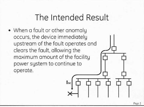
The Intended Result• When a fault or ather anamolyoccurs, the device immediatelyupstream of the fault operates andclears the fault, allowing themaximum amount of the facilitypower system to continue tooperate.

Assumptions When UsingTime Current Curves
• Current Magnitude is Constant• Reality is that current may beescalating, intermittent, variable.
• Depending on how the device operates,it may not perform as indicated on thegraph under variable current conditions.
Page 3
Available Settings forOvercurrent Protection
• "Pickup": The minimum level of currentat which the device will initiate a trip
• Time Delay: An intentional delay in timeto allow other devices to operate or toallow condition to clear itself.
l'a);c4
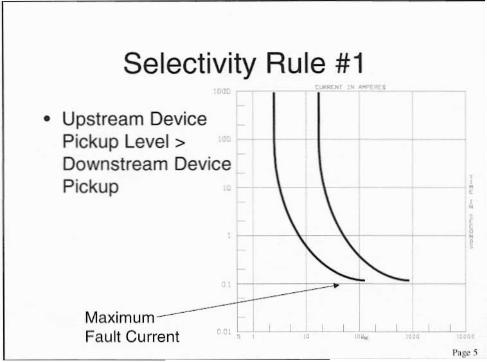
Selectivity Rule #1.-
• Upstream DevicePickup Level>Downstream DevicePickup
••
Fault Current " L ... .L I -L
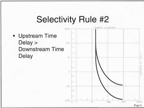
Selectivity Rule #2Cu.,,"
• Upstream TimeDelay> -+1--Downstream TimeDelay
t-t-
• • ..Page 6
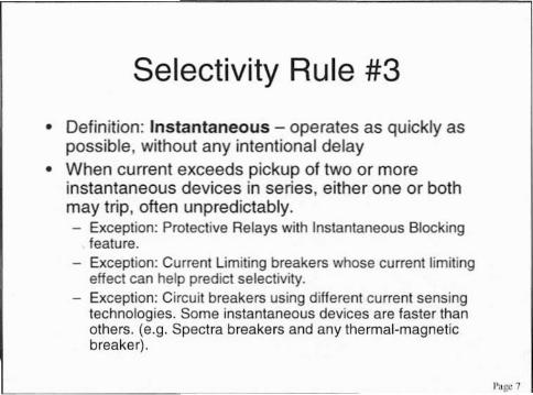
Selectivity Rule #3• Definition: Instantaneous - operates as quickly aspossible, without any intentional delay
• When current exceeds pickup of two or moreinstantaneous devices in series, either one or bothmay trip, often unpredictably.- Exception: Protective Relays with Instantaneous Blocking
feature.- Exception: Currenllimiting breakers whose current limitingeffect can help predict selectivity.
- Exception: Circuit breakers using different current sensingtechnologies. Some instantaneous devices are faster thanothers. (e.g. Spectra breakers and any thermal-magneticbreaker).
'>al)l' 7
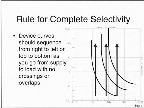
Rule for Complete Selectivity
01 --
• Device curvesshould sequence '"from right to left ortop to bottom as "you go from supplyto load with nocrossings oroverlaps
001 [,
(1'"-"" , <"',Ke
Poge 8
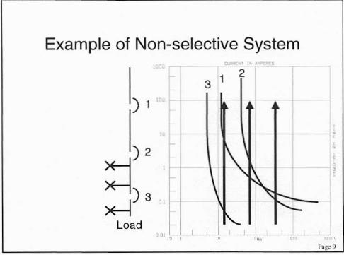
Example of Non-selective System2
3 1
) 1
) 2
>H) 3 "
LoadJ\" I
,
Corollary for Prevention ofNuisance Tripping
• Device curve(s) must be located eitherentirely to the right or above loadcurrent characteristic
• Usually applied with motors,transformers (inrush).
Page 10

Corollary for EnsuringEquipment Protection
• Device curve(s) must be located eitherentirely to the left or below equipmentwithstand characteristic
• Usually applied to transformers, wire &cable, busway.
I'age II
Selectivity Rule #4
• Complete selectivity is achieved rarelyin most industrial and commercial powersystems mostly for economic reasons.Achieving optimum results can be madethrough various compromises that arelearned mainly through experience.
r;o£c 12
·tt"
x ,
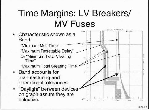
Time Margins: LV Breakers/MV Fuses
'''ff, t:
• Characteristic shown as aBand"Minimum Melt Time""Maximum Resellable Delay"Or "Minimum Total ClearingTime"
"Maximum Total Clearing Time"• Band accounts for
manufacturing andoperational tolerances
• "Daylight" between deviceson graph assure they areselective.
Page I.J
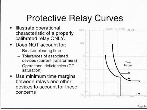
Protective Relay Curves• Illustrate operationalcharacteristic of a properlycalibrated relay ONLY.
• Does NOT account for:Breaker clearing time
- Tolerances of associateddevices (current transformers)
- Operational deficiencies (CTsaturation)
• Use minimum time marginsbetween relays and otherdevices to account for theseconcerns
leO) L -' ,,", ...."' X I
Ti"",
Page
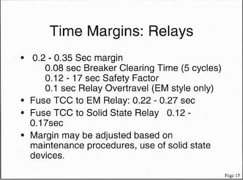
Time Margins: Relays
• 0.2 - 0.35 Sec margin0.08 sec Breaker Clearing Time (5 cycles)0.12 - 17 sec Safety Factor0.1 sec Relay Overtravel (EM style only)
• Fuse TCC to EM Relay: 0.22 - 0.27 sec• Fuse TCC to Solid State Relay 0.12-0.17sec
• Margin may be adjusted based onmaintenance procedures, use of solid statedevices.
PJge I
Put it All Together:An Example
• Individual Motor Load and Protection• Feeder Protection of MCC• Unit Substation Protection Main Breaker& Primary Fuse
Page 16
---II-If----------j -,<
I':GO
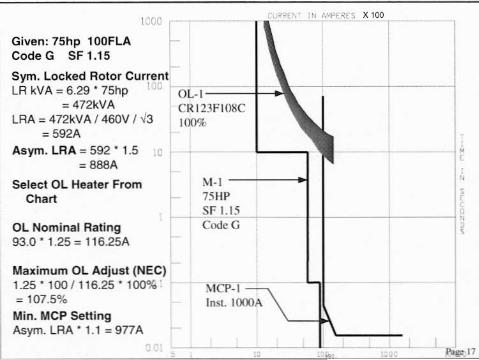
Given: 75hp 100FLACodeG SF1.15Sym. Locked Rotor CurrentlRkVA=6.29075hp I U I
= 472kVALRA = 472kVA /460V /..J3
= 592AAsym. LRA = 592 ° 1.5 :c
= 8BBASelect OL Heater FromChart
OL Nominal Rating93.0 ° 1.25 = 116.25A
CRl23Fl08C100%
M-l -------.I751-IPSF 1.15CodeG
,,",
Maximum OL Adjust (NEC)1.25' 100/116.25'= 107.5%Min. MCP SettingAsym. lRA' 1.1 =gnA
MCP-IInSI.IOOOA
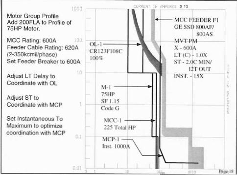
Motor Group ProfileAdd 200FLA to Profile of75HP Motor.
MCC Rating: 600AFeeder Cable Rating: 620A(2-350kcmil/phase)Set Feeder Breaker to 600A
Adjust LT Delay toCoordinate with Ol
Adjust ST toCoordinate with MCP
Setlnstanlaneous ToMaximum to optimizecoordination with MCP
- MCC FlGE 5S!) SOOAFI
ROOASDL-I V:r PM
X - 600ACRI23FI08CI(()% LT(C)-1.0X
5T - 2.OCITrOUT
IN5T.-15X
1>-1-1 ------.I75HI'SF 1.15CodcG
225 Toea! HP
lnst. I()(X).\
,
1",...-18
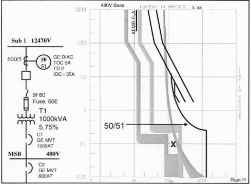
480V Base IN000 ilSub 1 12470V .0.
GE DIAC"'CSA"'2 ,1OC·35A +
utFro ,Fuse,SOETl ,l000kVA
50/51T 5.75%) C,
GE "'"'2OOAT
MSB ""'V) C2
GE "'"fiOOAT" 1'J:gor-19
The New Challenges
• Selectivity Req'd by 2005 NEC Art. 700• Arc Flash Concerns
Page 20
NEG Art. 700
• Legally required emergency systems• 700.27 - "Emergency system(s) overcurrent devicesshall be selectively coordinated with all supply sideovercurrent devices."
• Continuing debate in the industry as to whatconstitutes "selectively coordinated",
• Engineers do not want to be constrained to usingonly fuses.
• Interpretation of this paragraph differs widelybetween jurisdictions.
P"S" 21
Market Reaction
• Mfgrs are testing breaker combinations to establishselective combinations. No published data yet.
• Eleven proposals submitted to NFPA to modify orrepeal 700.27 - All rejected by the Panel.
• Some strategies:- Apply larger frame ratings- Apply ICGS instead of MCCB- Add ground fault protection
• Not all work among all mlgrs products• All add cost to the project
Page 22
Arc Flash• Increasing awareness in the marketto the injuries caused by arc flashincidents.Severe Injuries
• Government Regulations• Competing goal with selectivity
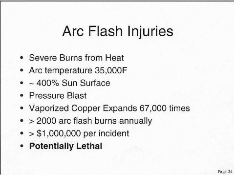
Arc Flash Injuries• Severe Burns from Heat• Arc temperature 35,000F• - 400% Sun Surface• Pressure Blast• Vaporized Copper Expands 67,000 times• > 2000 arc flash burns annually• > $1,000,000 per incident• Potentially Lethal

OSHAGeneral Duty Clause
29 • Section 5(a)(1):... Each employer shall
furnish to each of hisemployees employmentand a place of employmentwhich are free fromrecognized hazards thatare causing or are likely tocause death or seriousphysical harm to hisemployees
25
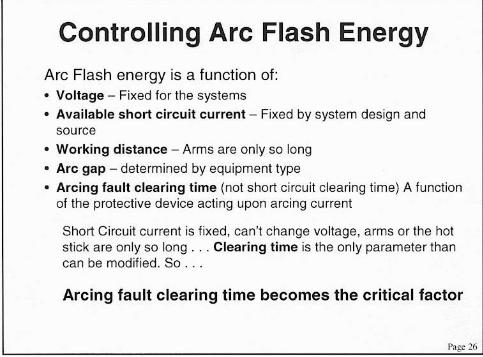
Controlling Arc Flash EnergyArc Flash energy is a function of:• Voltage - Fixed for the systems• Available short circuit current - Fixed by system design andsource
• Working distance - Arms are only so long• Arc gap - determined by equipment type• Arcing fault clearing time (not short circuit clearing lime) A functionof the protective device acting upon arcing current
Short Circuit current is fixed, can', change voltage, arms or the hoIstick are only so long ... Clearing time is the only parameter thancan be modified. So .
Arcing fault clearing time becomes the critical factor
Page 26
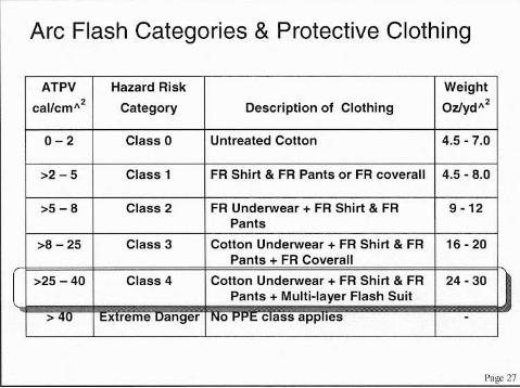
Arc Flash Categories & Protective Clothing
ATPV Hazard Risk Weightcal/cm,,2 Category Description of Clothing OzJyd,,2
0-' Class 0 Untreated Cotton 4.5 - 7.0
>, 5 Class 1 FA Shirt & FR Pants or FA coverall 4.5 - 8.0
>5 -8 Class 2 FA Underwear + FA Shirt & FR 9·12Pants
>8-25 Class 3 Cotton Underwear + FR Shirt & FR 16 - 20Pants + FA Coverall
I >25 -40 Class 4 Cotton Underwear + FA Shirt & FR 24·30Pants + Multi-layer Flash Suit
> .u I t:.X reme uanger 0 c ass app les -
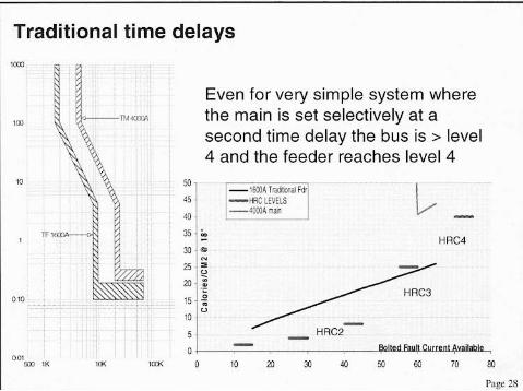
Tradilionallime delays
Even for very simple system wherethe main is set selectively at asecond time delay the bus is > level4 and the feeder reaches level 4
" " L.-"•., " . HRC4" .o.
HRC2
om:<:U lK lID( 0 10 20 J) «) 50 60 70 $J
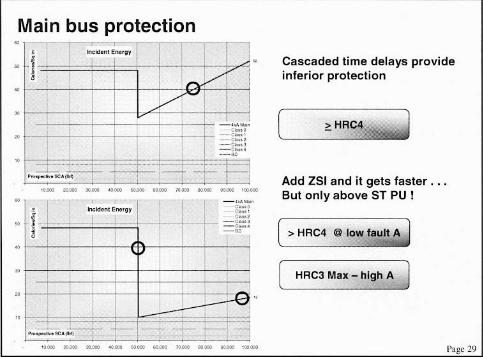
Main bus protection
Page 29
HRC4 I&' Rr tJ
Cascaded time delays provideinferior protection
Add ZSI and it gets faster . ..But only above ST PU !
( HRC3 Max - high A )
[ > HRC4 @ low A J
II ,../
j ""..-,,,,'., I _h.. _
• ._.._.I -g:::
-<....
I -0
I
I -I I• •.....•...- t 4
.. --"""'".- .- .- .- .- .- .- .- - .•
•
•
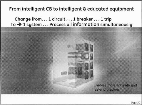
From intelligent CB to intelligent & educated equipment
Change from 1 circuit . .. 1 breaker . .. 1 tripTo -+ 1 system Process all information simultaneously
Page JO
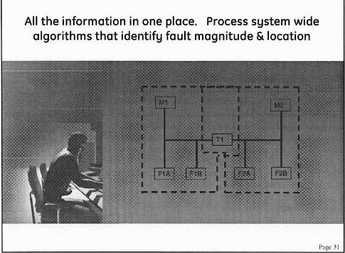
All the information in one place. Process system widealgorithms that identify fault magnitude & location
rage 31
- ......--10""'-'"'"
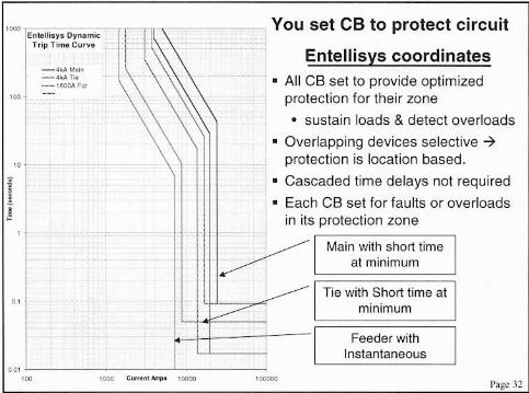
set CB to protect circuitDynamic
T,ipT;moCY".
Entellisys coordinates• All CB set to provide optimizedprotection for their zone• sustain loads & detect overloads
• Overlapping devices selective -7protection is location based.
• Cascaded time delays not required• Each CB set for faults or overloadsin its protection zone
I!
"
Main with short time
:===a=,=m=,,=,=m=u=m==;Tie with Short lime at
minimum
Feeder withInstantaneous
00' "-------:--:---:-'--:--:-----:'00 '000 C"''''' _ '0000 ,"""""
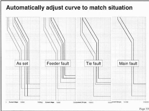
Automatically adjust curve to match situation
As set Feeder fault
J
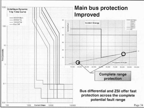
· iMain bus protectionImproved
• -,-,-,_.-'-I•
:<:::...,,- --.7" -- ..- ,,- -- --
"-'<- Complete range Iprotection _J..
..
,.
;:::;;::""Oynomlc:ITripnm.C" ......_<.OOOA"u_<000' too_'fOO,\'o-_8.. 0.
I!
,.'. , 'o:oc
Bus differential and ZSI offer fastprotection across the complete
potential fault range

GE imagination at work