THErheckathorn.weebly.com/uploads/2/7/1/0/27107965/the... · · 2016-09-09A MODULE ON RIGID BODY...
94
THE ELECTRIC FAN A MODULE ON RIGID BODY ROTATION PRINCIPAL AUTHORS: John W. McWane, Technical Education Research Centers Malcolm K. Smith, lowell Technological Institute lim Technical Education Research Centers Coordinated by the American Institute of Physics
Transcript of THErheckathorn.weebly.com/uploads/2/7/1/0/27107965/the... · · 2016-09-09A MODULE ON RIGID BODY...

THEELECTRIC FAN
A MODULE ON RIGID
BODY ROTATION
PRINCIPAL AUTHORS: John W. McWane,Technical Education Research Centers
Malcolm K. Smith,lowell Technological Institute
limTechnical Education Research Centers
Coordinated by the American Institute of Physics

PHYSICS CONSULTANTS: ••••tlYniei H. Fr_nk,Massachusetts Institute of Technology
Ernest D. KIeIn_,Tufts University
"Copyright C 1973 by the Technical EducationResearch Centers Inc. Printed in the UnitedStates of America. All rights reserved. Thisbook, or parts thereof, may not be reproducedin any form without permission."
The materials contained herein were de-veloped pursuant to a contract with theNational Science Foundation, Grant NumberGJ 9317.
TERC Curriculum Development Laboratory
575 Technology Square
Cambridge, Massachusetts
02139

PREFACEAbout The Physics Of Technology Modules:
The physics of Techno- you can do to test whetherlogy modules provide a you have achieved the ob-course in experimental phy- jective.sics primarily for the . .t h' 1 t d t Th ppepequ~s~tes to the moduleec n1ca s u en. e , d' th k'll dmethods of presentation 1n 1cate e s 7 s an ,, knowledge you w111 use 1ntherefore d1ffer from those th d 1 b t 'II t bof standard materials. This ,e mo u e, u ,W1 no e
f h' hI' ht f d1scussed. Lack1ng one orpre ace 19 19 s some 0 f dthe features of the module two 0 these sho~l not pre-so that you can use it ef- vent rou from d01ng the mod-f t' 1 d ff' 'tl ule S1nce they can be learn-ec 1ve y an e 1C1en y. ed as you go along. However,
if you lack more than thatyou might begin with anothermodule whose prerequisitesyou have or take time out tolearn the missing ones.
,THE TITLE:
Each PoT module is centeredon a device or system thatis familiar to you or thatyou may meet in a later worksituation. The operation ofthe device will generallydepend on some area of phy-sics that is relevant tothe technology involved.This area of physiqs islisted in a secondary titlefor the module.
THE INTRODUCTION:A brief introduction ex-plains why we have chosenthis particular device andwhat principles of physicswe expect you to learn fromit. Several examples aregiven to show why theseprinciples are importantand where else you may en-counter them.Objectives are then givenfor the module. These in-clude a general discussionof the goals of the moduleas well as specific thingsyou should be able to do todemonstrate that you haveachieved these goals. Aftereach objective is listedthe pages in the text whereit is discussed, and Ppo-bZems and Questions that
THE THREE PARTS:The module is divided intothree self-contained parts.Each part is designed to becompleted in about one week'stime.
PART I is usually devotedto familiarizing you withthe device, the instpumen-tation you will use tomeasure its performance,and the tepms that describeits characteristics. Oftenthis will mean learning howto use a new measuring in-strument or transducer.
PART II generally focuseson an experiment involvingsome specific behavior ofthe device. The laboratoryinstructions are explicitas to experimental proce-dures. They tell you indetail how to take, graph,and analyze the data. Thisis to familiarize you withthe expepimentaZ methods in-volved with this area ofphysics.

PART III generally will in-volve doing some additionalstudies of the behavior ofthe device. You will usethe instrumentation learnedin the first week and themethods of data taking andanalysis learned in thesecond week.
THE ROLE OF THE LABORATORY:·Since this is primarily ap~ogram in experimentalphysics, the material empha-sizes the experimentalactivities. A short intro-duction will orient you tothe experiment you will do,and to the important phy-sics principles or skillsthat you should learn. Theexperiment, including theset-up and data taking pro-cedures, then follows im-mediately.
The principal experi-ment is often preceded bysome simple ones. Theseare included to give youa feel for what you will bedoing in the main experi-ment. They generally can bedone quickly and do not re-quire extensive data taking.The principal experiment,however, should be donecarefully since the remain-der of the material will dis-cuss this data.
Once your experimentalwork has been completed andall of your data taken, youcan leave the laboratory.The remainder of the mater-ial is devoted to helping
January 1973
""ER:Cambridge~ Massachusetts
you graph and analyze yourdata while explaining thephysics involved. This workcan be done either as home-work or in class with yourinstructor. Tear out pagesfor data and graphs are pro-vided in the module as theyare needed.
In reading the mater-ial be sure to keep in mindthe module objectives. Al-though the material gener-ally goes beyond what isneeded to achieve them, yourtest at the end of the mod-ule will be on those objec-tives.
FinaZZy~ the module hasbeen designed to provideyou with an understandingof physics that will beuseful to you. Within thetext you will find conver-sion table, methods forcalibrating transducers,explanations of physicalterms, comparisons of waysto measure a physicalparameter, and so on.These could be of use toyou sometime and you maywant to tear them out tokeep as reference material.
I hope that thematerial in these Physicsof Technology modules willprovide you with the skillsof experimental science andinsight into the physicalprinicples underlying yourtechnical field.
John W. McWaneProject Director

CONTENTS
INTRODUCTION. . . . . . . . . . . . . . . . . . . . . . . . . . . . . . . . . . . 1MODULE OBJECTIVES 3PREREQUISITES.. 5
INTRODUCTION .EXPERIMENTS:
Learning to use the Strobe. . . . . . . .Direct Measurement of Rotational Speed. . ..Using a Vibrating Reed Tachometer . .. .Calibrating a Tach Generator .Relating Angular Speed and Number of Revolutions.
DATA ANALYSIS AND DISCUSSION .REVIEW:
. 13
. 13· . 14· . 15· . 16
.19
Summary . . . . . . . .Conversion Tables . . . .Questions and Problems.
.26
.26· .27
INTRODUCTION .EXPERIMENTS:
Measuring Stalling Torque . . .Measuring Dynamic Torque ...Determining Moment of Inertia .
DATA ANALYSIS AND DISCUSSION .REVIEW:
Summary . . . . . . . . . . .Conversion Tables . . . . . . . . .Questions and Problems. .. . ...
. . . . .. .. 31. . . . 31
· 31.35
· 47· . .. .48
. . .50
PART m: STATIC AND DYNAMIC BALANCE 53
INTRODUCTION. . . . . . . . . . . . . . . . . . . . . . . . . . . . . . . . 53EXPERIMENTS:
Observing the Effects of Unbalance. . . . .. . .56Achieving Static Balance. . . . . . . . . . . .. .57Observing Dynamic Unbalance. . .. . .58Achieving Dynamic Balance. . . . .. . 59Using the Flexible Table Dynamic Balancer •..... 60
DATA ANALYSIS AND DISCUSSION. . . . . . 63REVIEW:
Swnmary . . . . . . . .Questions and Problems ..
. . . . . 72. . . 73


INTRODUCTION
In this module you are go-ing to study the electric fanbecause it can be used to illus-trate some important principlesof physics. We all have usedfans to stir up a breeze andhelp us keep coolon a hot day.But in this module you will notstudy air motion or the actionof the fan blades. Instead, lour
interest is in rotation -the behavior of spinningbodies, automobile tires,gyros, and many other rotat-ing objects. We will use theelectric fan because it isinexpensive, convenient toinstrument and its rota--tional speed can be easi-ly controlled.
IBallIKe Wheels Quickly,-bsily~-Accurateli with thisHeavy-Duty Precision WHEEL BALANCER
Fot All Can, Including Compact., St.tion Wagons and Imported CarsRuggedly built. precision accurate balancer haslarge self-centering ta~ered sliding spider. Cen-ters any size wheel,_ even wt'-eels with out·of-round center holes, Instantly and automaticallywithout adjustment by tl'-e operator, Ideal forbalancing wheels when changing to or fromsnow tires, when installing new tires. Built-incircular spirit level jnsures precise wheel bll-anee. Free moving bubble checks wheel balancein all directions. Free-swing pendulum assuresmaxjmum sensitivity of balance. Built-in fea-
i~:::rj~~I~d~~a~r~;d6a:~CaT=~11Wa~e:'xtSr~P~~~~B.I.nced Wheel. . . stand. Approx. '2" high. Strong welded steel1. Giye a .a'er, .",ooth~ construction throughout. Guaranteed against aller more com'ort.ble defects in workmanship and materials-will beride. repaired or a.choln.ed only. Cannot be ,.tumed
'or credit or ""und. Fits all cars except Porsche,2. Help prevent front Peugeot, Renault, Volkswagen, and other Car$"end we.r and dam•• e. with closed center wheel hubs. Can be used on
Volkswagen, 58ab, and other imported cars with3. Reduce une".n tire large center holes by addino wheel balancer
~::' - incre •••. tire ~~~~~~~~~ep~~~; 9 Ibs..... Each $22.45
[AJ- ...:~~~=...::;,;..::?:-
Counter Weightsfor balance" \
Balancing AutomobileWheels: Automobile wheelsneed to be properly bal-anced. The machine shownis a static balancer,which means that thewheels will be in balanceas they stand or at lowspeeds. Usually this isadequate. Sometimes, how-ever, wheels may be stat-ically balanced, but outof balance dynamically,that is unbalanced at highrotational speeds.
Balancing Crankshafts:Automobile engine crank-shafts must be dynamicallybalanced with great care.The crescent shaped piecesopposite are counterweights,carefully located and ofjust the right mass. Dynam-ic balance is attained bythe placement of weightsall along the crankshaft.Unbalance in a modern, high-speed engine could quicklydestroy it.

Storing of Energy: The fly-wheel shown (finned to actas a cooling fan) is boltedonto the end of a lawn mowerengine crankshaft. Flywheelsare particularly importantin one cylinder engines likethis since there is only onepower impulse in every tworevolutions. The flywheelstores the energy of thepower stroke until the nextone occurs. This storedenergy keeps the engine andits parts moving smoothlyand at a steady angularspeed.
~
S••P1.-ston .~ Flywheel
)
~@i !.-inne~ forCool1.-ng
~ Balance On~~ Crankshaft
PART I THE DESCRIPTION OFROTATION: KINEMATICS. Kine-matics is concerned with howmotions take place: howfast? where? when? Rotation-al kinematics is describedby angular speed, such asthe rpm of an engine, and bythe angle turned, such aswhen a building crane swingsfrom one position to another.Often the relation betweenstraight line motion androtation is what counts. Forexample an automobile odo-meter reads distance travel-ed as the wheels turn. InPart I of this module youwill study the behavior ofthe electric fan to learnabout its rotational kine-matics.
PART II THE CAUSES OFROTATION: DYNAMICS. Dynam-ics tries to answer suchquestions as: what caused awheel to slow down? how muchtorque can an engine exert?why do gasoline engines need
flywheels and how shouldthey be made? Our mainconcern in Part II will bewith the torques that causechanges in rotation, andwith the rotating behaviorof bodies of various sizesand shapes.
PART III STATIC ANDDYNAMIC BALANCE. Balancemeans much more than justtwo kids at either end of asee saw. The principles ofbalance tell how an automo-bile engine crankshaft mustbe built, if the engine isto run smoothly and not vi-brate excessively. Everyturning wheel must meet thespecial conditions calleddynamic balance or greatstrain will be put on theshaft and perhaps the bear·'ings will be destroyed. InPart III you will learn thethe difference between sta-tic and dynamic balance andmethods for achieving themfor a rotating body.

The general goal of thismodule is to give you an un-derstanding of the importantfeatures of rotational motion.You will see how these princi-ples are applied in real rota-ting devices.
This involves a knowledge
The kinematics of ro-tation; that is, thedescription of angu-lar motion in terms ofangles, angular speed,and their relation tolinear motion.
Instruments used inobserving and measur-ing rotational motionsuch as tachometers,revolution counters,and stroboscopes.
The dynamics of ro-tation: includingthe relation be-tween torque, mo-ment of inertia, andchange of angularspeed.
Static and dynamicbalance, and methodsof statically anddynamically balanc-ing a rotating body.
At the end of this moduleyou should be able to demonstr-ate your understanding of itsobjectives by doing the follow-ing:
(PART I)1. Explain how to use a stro-
boscope to measure angularspeed.
2. Use a stroboscope to makea calibration graph for atachometer generator.
3. Make a graph of angularspeed against time anduse the area under thecurve to calculate thetotal number of revolu-tions.
Pages·Where
Discussed
Problemsand
Questions
Q - 1P - 1
Q - 2P - 2,3

4. Use the angle turned tocalculate the linear dis-tance moved by a point ona rigid body.
5. Use the common units ofangle measure, degreesand radians, in calcula-tions and explain whyradian measure is oftenpreferred.
(PART U)
6. Explain the concept oftorque, including stal-ling torque and dynamictorque.
7. Explain moment of inertia,I, and calculate it forbodies of various shapes.
8. Use the basic rotationaldynamic equation:
6wT = I6tto analyze changes in ro-tational motion.
9. Use the dynamic equationto determine the moment ofinertia, I, of a rotatingbody from its behaviorunder constant torque.
10. Explain the purpose anddesign of flywheels interms of rotationalkinetic energy.
(PART m)11. Statically balance a rotor
when provided with a simplebalancing machine.
PagesWhere
Discussed
Problemsand
Questions
Q - 3,4P - 4,5,6
7 &. 8
Q - 1,4P - 1,2
Q - 2,4,5P - 3,4
Q - 4P - 5,6,7
Q - 2,5P - 5,8
Q - 1P - 1

Pages ProblemsWhere and
Discussed Questions
12. Dynamically balance a 60,61simple rotor using a dy-namic balancing table.
13. Describe static balance 63,65,66 Q - 2in terms of center of P - 2mass.
14. Explain reaction force 63,65,68 Q - 3,4and calculate its magni- P - 3,4tude.
15. Describe dynamic unbalance 68 Q - 5in terms of reaction force P - 5and wobble torque.
Before begining thismodule you should alreadyhave the following skills,since they will be used, butnot described, in the module:
1. graphing data on lin-ear graph paper;
2. using scientific nota-tion;
3. solving simple alge-braic equations;
4. reading meters andusing a stop watch;
5. using elementary geo-metry; measuring ang-les and finding areasof rectangles and tri-angles;
6. using the idea of rate;distance or revolution,or some other quantityper unit time.
If you are unsurewhether you have theseprerequisites, ask yourinstructor to give youa prerequisites test.
If you find you donot have a certain pre-requisite, ask your in-structor to give youmaterial to help youlearn the needed skill;or have someone help youlearn it as you need itin the module.


7
PART I
ROTATIONAL KINEMATICS
In this module, we wantto talk about rotation in a
,useful way, and that meansin a quantitative way. Thatis, we must describe rotationusing numbers; measurementsthat tell how fast, how far,
The performance of a re-cord player turntable is mea-.sured by its ability to ro-tate. It must also maintainthis rate regardless of thenumber of records it mustturn. The rate of rotation is33-1/3 revolutions per minute(rpm). Angular speeds are ex-pressed as the number of re-volutions (or the angle turn-ed) per unit time.
All points on a record(or any rotating rigid body)
move at the same angularspeed. When the body hasturned through one revolu-tion, all points on it havealso turned through one re-volution.
But what about the lin-ear speed of the points? Lin-ear speed means the lineardistance traveled per unittime, for example inches persecond. A point near the edgeof a record covers a muchgreater linear distance inone revolution than a pointnear the center. For example,the needle on the recordmoves along the grooves atthe linear speed. When theneedle is in a groove out
how much a rotating body hasmoved.
The first part of themodule is concerned with ex-plaining the definitions ofthese quantities, and howthey are measured.
hll points move atsame angular speed
but linear speed de-pends on the distancefrom center.

near the edge, its linearspeed is about 20 inches persecond, while near the center,it is only about 7 inches persecond even though the angu-lar speed is constant at33-1/3 rpm.
This notion is particu-
larly important for airplanepropellors since it sets anupper limit to its diameterfor a given rpm. If the dia-meter is too great, the lin-ear speed of a point on thetip may exceed the speed ofsound with disastrous re-sults.
With many rotating devic-es, it is essential to knowthe anglular speed at alltimes. The engines of shipsand aircraft and high perfor-mance cars must be operatedwithin a certain range of
Electronic Tachometers:Most automobile and boattachometers are now operat-ed by electrical pulsesfrom the ignition system.An electronic circuitcounts the number of pulsesper minute and displays thecount in-rpm on a meterdial.Vibration Tachometers: Vi-bration tachs are metalstrips (called reeds) thatvibrate strongly at a par-ticular rate of vibration.Such tachs are often usedfor extreme ley accuratemeasurements over a verynarrow range. For example,portable electric genera-tors must be operated atjust the right angular speedto give a.c. voltage of 60cycles per second. A vibra-tion tach is usually builtinto such a generator. Youwill see how these vibratingreed tachs work in your ex-periment.
angular speeds. Electric gen-erators must turn at precise-ly the right speed. Angularspeeds are measured by in~struments called tachometers3
or tachs for short.
'31.4" 21r •••• ..swEO"TRAIISISTORIZED
TACH
• Precision (HO,OOO RPM Scale• For 4, 6, or 8 Cylinder
J.G. BIDDLE "Frahm" 4999GS• 3-1/2" ROImd Panel MountRange: 400-440 cps.Input: 105-150.VAC11 Vibrating Reeds: 4 cps increments
S995

The Tachometer Generator: Adc electric generator can bemade into a tachometer. Thearmature of a dc generatoris a coil of wire wound on aniron core. It rotates in themagnetic field of a magnet. Asthe armature turns an electricvoltage is produced in thewires which depends on thespeed of rotation. This vol-tage can be a linear functionof its angular speed. That is,the voltage measured on thecoil is directly proportionalto its speed of rotation. Ifthe generator is attached to
some rotating device, its out~put voltage will then indicatethe angular speed of the de-vice.
A dc motor has the samebasic design as a dc generator.If its armature is rotated, avoltage will be generated atthe motor terminals that de-pends on the angular speed ofrotation. In the first experi~ment you will convert a simpledc motor into a tach generator.Later you will use it to mea-sure the dynamic behavior ofthe fan.
DC PM TACHOMETER GENERATORSTYPE
BYLMFYLM
FRAME MOMENTSSIZE OF INERTIA
HYLM 4----- 8.32 x 10.3 Ib-in2
BYLM 7--- 12.53x 10-' Ib-in'
BYLM 9--- 17.97x 10" lb·in'
BYLM BYLM BYLM FYLM FYLM FYLMTYPE NUMBERS 43820·XX* 73820-XX* 93820·XX* 23920-XX* 43920-XX* 73920-XX*
Rated outputs (open circuit). 6 volts 12 volts 24 volts 3 volts 5 volts 10 voltsNote: Consult factory if application per per per per per perexceeds 100 volts or 7000 rpm. 1000 rpm 1000 rpm 1000 rpm 1000 rpm 1000 rpm 1000 rpm
Rated output tolerance. Calibrated within ± 1% in specified direction of rotation.
IOutputs in opposite directions will be equal to each other within 2%.
Linearity errorPer definition (1) above:
± 0.5 % of output at 7000 rpm or ± 0.5 volts, whichever is smaller.(above 500 rpm) Per definition (2) above: ± 1% between 500 and 10,000.
rms ripple voltage. 3% ma,ximum above 100 rpm. 3% maximum above 100 rpm
Nominal armature resistance of gen-80 ohms 110 ohms 160 ohms 70 ohms 90 ohms 130 ohmsera tor having outputs quoted above.
Ambient temperature range. --65°F to +200°F -65°F to +2oo°F
PRICE EACH S 92.70 101.30 107.50 79.10 79.10 81.50
How do you determine therpm corresponding to a partic-ular voltage of a tach genera-tor? Finding the relation isan example of the processcalled caZibration. Thus weneed some device whose angularspeed we know, or another pre-
viously calibrated tachometerto compare it with. For yourexperiment you will use astroboscope as the caZibrationstandard for such a comparison.The stroboscope is still an-other type of device for mea-suring angular speed.

THE STROBOSCOPE
The stroboscope, orstrobe, is an extremely use-ful tool because it providesa way of observing any kindof repeating motion as thoughit were stopped. It does thiswithout making any connectionto the moving object. An elec-tronic strobe circuit produc-es very short and very brightflashes of light at regularintervals. A short flash isimportant because the objectmust move very little whilethe light is on; otherwise theimage would be blurred.
The strobe is adjusted sothat the time between flashes
Rotatinggrinder(1700 r~vmln
~~
When the flash rate exaatlyequals the rotational rate~ thewheel is in the same positioneaah time the light flashes on.Your eye only sees the wheelin that position and you thinkit has stopped there.
is exactly equal to one per-iod of the object's motion,for example the time for onerotation. In this way, apoint on the rotator is only"seen" at one place and ap-pears "stopped" at that place.
Stroboscopes are widelyused in industry to observeotherwise invisible detailsof the motion of high speedmachinery. A simple kindos strobe is used, for ex-ample, to stop the motionof automobile engines in or-der to properly adjust theignition.
lamp (1700 fl.ashes)mlnute
Calibrateddial controls
flash rate
A strobe can be quite ac-curately calibrated electronic-ally and thus is often used asa standard for calibratingother kinds of tachometers.Strobe dials are generallymarked in rpm so that the dialsetting that stops the motiongives the angular speed of therotating device. This is par-ticularly useful if the angu-lar speed is constant.
If the speed is changingrapidly, however, the strobewill not keep pace with it.Then tachometers that read con-tinuously are required. In theexperiment you will use thestrobe as a standard to cali-brate the tach generator whenthe fan is rotating at con-stant speed. The tach willthen be used to measure thespeed when it changes rapidly.

In using a stroboscopethe first step is to makesome easily distinguishablereference mark on the rotat-ing system. A scratch, apaint spot, a nut, or anyother similar mark will serve,but it is essential that itbe the only mark of its kind.
When the system is rotat-ing, the goal is to increasethe strobe rate until thatmark appears to be stopped andnot rotating. It is worth not-ing that this stopped imagemay appear so real that youmay actually believe it is notrotating. However, do not stickyour finger in the system tosee if it is rotating. Insteadchange the strobe rate to see
OBSERVATIONDIM: too low
if the mark moves.There is more than one
rate that appears to stop themotion. Rates that are frac-tions of the real rate willappear to stop the motion andmultiples of the rate may stopthe mark, which will appearsuperimposed on other marks.Can you figure out why? Thuswe state:THE BASIC RULE: The true rota-tional rate is the higheststrobe rate that stops the mo-tion of the reference mark andonly the reference mark.
The illustration belowshows what you might see witha rotating disk when the mo-tion is stopped.
The motion is stopped, but thestrobe rate is not correctly matched tothe angular speed. If the strobe rate ishalf the angular speed, then the rotatormakes exactly two revs between flashes.You would still see the motion as stop-ped, but the reference spot would be dim.
There is just one revolution in thetime between flashes and one image of thereference mark. Test your strobe rate bydoubling it: if two images appear, youwere right on; go back to the previousrate.
The time between flashes is not longenough for a complete revolution. For ex-ample, if the strobe rate is three timesthe angular speed, there is 1/3 revolu-tion between flashes. Three images of thereference spot appear in different places.

The Fan should be verticallypositioned on a flat surfaceand plugged into the variablevoltage supply. The fanswitch should be turned toHIGH. The fan blade should befirmly mounted to the motor.Make an easily visible refer-ence mark on the hub.The Variable Voltage Supplyshould be plugged into a 110volt outlet. Changing the vol-tage supplied to the fan willchange its rotational speed.The Strobe should be posi-tioned so it will shine onyour reference mark on thehub. The room light should belowered so that the strobeflashes show up brightly.The Tach Generator is mountedon the front screen and cou-pled to the fan shaft by a
rubber sleeve. Be sure thiscoupling is firmly seatedand will not slip.The Digital Counter is gear-ed to the tach generator andrecords directly the numberof revolutions of the fanblade.The Meter should be a dcvoltage meter with a rangefrom 0 to 1 volt. Connectthe meter to the outputterminals of the tach gen-erator.

THREE SIMPLE EXPERIMENTSLEARNING TO USE THE STROBE:
PROCEDURE:1) Turn on the poLt~~e
suppLy and increase the vol-tage to a maximum so that thefan blades are turning at topspeed. Note the voltage pro-duced by the generator.
2) Turn on the strobeand set it to read about 1000rpm.
Increase the strobesetting sLowLy while watchingthe hub, until your referencemark is stopped by the flash-ing strobe.
31 EZ~Zore the beh~pi.orof the reference spot whenyou pass through the exactstrobe rate that stops themotion. Which way does thespot move when the rate isslightly too high? .too low?
Vary the rate todouble, one half, etc. ofthe true rate.
4) Adjust the stroberate until the referencemark is exactly stopped.
The most direct way tomeasure rotational speed isto count the number of revolu-tions in a given time period.To count the number of revolu-tions you can use the digitalcounter attached to the tachgenerator.
Keep strobe matchedCD to fan's rotational
speed.
The counter itself regis-ters every tenth of a revolu-tion. However, the ratio ofthe gears was made ten to oneso that it now reads directlythe number, n, of revolutionsof the fan. Follow the proce-dure in the illustration below.
Start stop watch~ when counter
passes 000.Stop watch at
~ end of 1000rev. Recordtime.
------@)
Calculateilverageangularspeed.
fP:\ aake several'-V trials.
n turnstime interval in minutes

Earlier we discussedbriefly the vibrating reedtachometer. In this experi-ment you can see how the vi-brating reed tach works.
Bolted to the side ofthe frame is a thin stripof spring steel. Beingspringy it snaps back whenpushed aside. Anythingspringy tends to vibrate ata certain fixed rate or fre-quency. This natural fre-quency depends on the massand the stiffness of thespring. The combination ofsmall mass and stiff springmeans a high frequency. Alarge mass and weak springmeans a low frequency. For
the reed the natural frequ-ency can be changed by simplychanging its length. Thelonger the reed the lower thenatural frequency.
When the reed is attach-ed to the fan, the small vi-brations of the fan will makeit vibrate. If you watchclosely, you will see thatthe reed vibrates a little atany fan rpm. However, it willvibrate most strongly whenthe fan rpm is equal to itsown natural frequency. Thisstrong response is called re-sonance. Follow the procedureat the top of the oppositepage to see how the principleis used to make a vibratingreed tachometer.

PROCEDURE:1) Adjust the length o~
the reed until it is aboutsix inches long. Clamp itfirmly at this length.
Record its length inthe table following page 16.
Snap the reed so thatit vibrates back and forth.
2) Measure the naturalfrequency of the reed usingthe stroboscope. The samegeneral rules for using thestrobe to measure the angularspeed of rotating systems ap-ply to using it to measurethe vibration frequency ofvibrating systems.
Record the naturalfrequency o~ the reed,
3) Turn on the fan andadjust its speed until theamplitude of the reed vibra~tions is a maximum.
Record the tachometervoltage at this resonantspeed.
4) Increase the lengthof the reed by about an inchand repeat your measurements.
Record your results,
5) Decrease the lengthof the reed by two inchesand repeat.
AN EXPERIMENT...• • •TO CALIBRATE A TACH GENERATOR
In this experiment youwill calibrate a dc motor asa tach generator. The motoris coupled to the rotatingfan so that it is being driv-en as a dc generator. Thevoltage output of the motor-generator will be compared tothe reading of the calibratedstrobe which is set to juststop the motion of the rotat-
1) Set the fan speed withthe variable voltage supplyuntil the output of the tachgenerator is stable at thenearest tenth of a volt belowthe maximum output.
2) Change the strobe rateuntil you exactly match therotational speed.
ing fan.Several readings of tach
voltage vs rpm should be madecovering the full range offan speeds. From these data acalibration graph can be madefor later reference. The de-tailed steps of the experi-ment and important notes aregiven below.
3) Record your valuesof tach voltage and stroberate in the table followingpage 16.
4) Repeat the measure-ment for every tenth voltoutput of the tach generator.Carry this down as low asyou can.

By this time you shouldbe familiar with the variouscomponents of the apparatusof this module. As a finalexperiment you will examinethe manner in which a rotat-ing object slows down. Sincethe fan blade is light andits blades interact stronglywith the air, it slows downtoo quickly for study. Thusyou will replace it with aheavier metal disk that takessomewhat longer to slow down.
In this experiment youwill record the angular speedof the disk at equally spacedtime intervals as it slowsdown.
At the same time you willcount, with the counter, thetotal number of revolutionsthat the disk makes from thetime you shut off the power.Later you will see that totalrevolutions and angular speedare closely related.
Since the data must betaken quickly, it is best iftwo persons work together.One can call off the time in-tervals while the other re-cords the tach generator out-put. Follow the procedurein the diagram below, and re-cord your data in the tableprovided.
Turn on fan tomaximum speed.
When counter passes000 sioultaneouslyturn off fan andstart stopwatch.
MetalDisc
Record tach gen-erator output at5 second inter-vals, and recordtotal number ofrevolutions.
Make threetrials.

Vibrating ReedFrequency
TrialLength
Natural frequency(from strobe)
Tach Voltage at·Resonance
Rotational Speedat Resonance(from calibrationgraph)
Tach GeneratorCalibration
Generator Strobe rateVoltage (rpn)(volts) .

Slow downBehavior
Time, Tach Rev. Rev. Tach Rev. Rev. Tach Rev. Rev.See Volts Min. Sec. Volts Min. Sec. Volts Min. Sec.
0
5
10
15
20
25
30
35
40
45
50
Total numberof revolu-tions from:

DRAWING THE CALIBRATION GRAPH
Writing your data in atable is generally the fast-est and most accurate way torecord them during the heatof an experiment. However,when you later want to get apicture of what was happen-ing, or estimate values be-tween the points you took, agraph of the data may be moreconvenient.
This is particularlytrue of the data you took oftach generator output vs rpm.Since you want to use thetach generator as a tool tomeasure rotational rates, youwant to convert the voltagereadings to rpm quickly.
tCependentVariable
IndependentVariable
o 100 :ltJo 300 Ik>o..YI31.41ltt- ~fepd (ypn,)
If the relation turnsout to be linear; that is, iftach voltage is directly pro-portional to rpm, then youcan convert any voltage read-ing to rpm by multiplying bya constant. Follow the pro-cedure below to get a cali-bration graph for your tachgenerator. Use the graphpaper provided on the follow-ing page.
1. CHOOSE AND LABEL AXESNormally you put the
quantity that you can change(the independent variable)on the horizontal axis.Therefore we choose thehorizontal for the rpm set~tinge Tachometer voltage isa reading that follows fromyour setting (dependentvariable) so it is on thevertical axis. Both axesshould be labeled with thenames of the variables andtheir units.
2. CHOOSE AND LABEL SCALESYou should choose the
number of units per divi-sion so the range of yourdata nearly fills the paper.Be sure to choose conven-ient divisions that areeasy to plot. For example,10 divisions to be 100 rpmor .1 volt.
Indicate which divisionsyou have chosen by putting alight hatch mark next to theline with the appropriatenumber.

3. PLOT THE POINTSEach point on the graph
represents a pair of valuesfrom the table. For example,suppose one pair is 0.17volts and 250 rpm. The desir-ed point on the graph is theinterse~tion of two imaginary,perpend~cular lines from thosepoints. Put a small dot at theintersection. Since dots arehard to see, it helps to putsome geometrical shape aroundor through it such as: 0, 8,A, X. to make it more visible.Be sure that the shape is cen-tered on the dot.4. DRAW A SMOOTH CURVE
The measured points willprobably not fall perfectlyon any straight line or curve.If the points look close tobeing on a straight line, drawa line that follows their gen-eral trend. There should bethe same number of points a-bove and below the line. Ifthe points seem to lie along acurve, try to judge its shapeby eye, and draw a smoothc~rve. ~on't connect the pointsw~th a Jagged line. The angu-lar speed and voltage changedsmoothly, not erratically.
Be careful in drawing thisgraph. It is a calibrationgraph and all your data afterthis will depend on your workhere. A straightedge ordraftsman's French curve willhelp you draw your curve ac-curately.
5. TITLE YOUR GRAPHThe graph should be titled
s~ that anyone, including you,w~ll know what it represents.You should include what thetwo variables are, how theywere measured, what specificapparatus it refers to, whenit was measured and by whom.
.tT-till
It>t> 2~ 3CD ~«> S-a..."'St.tlqr sp~€d (rp"t)
6. CALCULATE THE SLOPEYour curve should be a
straight line. This is con-venient since a simple con-stant can be used to deter-mine the rpm from anyvoltage reading. This con-stant is the slope of yourline.
Since the line goesthrough 0, the slope canbe calculated from any pairof points that lie on theline. For best accuracychoose the largest valuesthat lie on your line. Sim-ply divide the rpm readingby the corresponding tachvoltage to give the numberof rpm per volt. This num-ber multiplied by any vol-tage reading will give thecorresponding rpm. Try it.
r;"" Vo/t4~C VI "PMfoe:- t~c." 9 ••• "ii 3"'S'Iot~ 1)r"'d~e. # "I 45,aliot-o.1"/o"" "tcu"dArd
b~ R. P £~M .5/23/'3

CALIBRATION GRAPH
00 tttt-trt"t"ti-
~rl11fl11111 "fIr-liT-Ii ' LH
I
rtCDPIIi
0+fIHTIITTIIHTImJE m JJI III rIII In ITJmill mmmi III ED fimm ill milT!III rnIn rm:c ' ~ C
rtL '
toPI\QCD""- I
++I-~,.n* ft4+j:i:-H·
!- i~- . -++t+!-1+t+'1:p..;
I·P~ .eH L .r tffi: 1 . !-,++ . -;-f ,l:J::mt.Li-i+ 1 ,
+-+ ". +H.tt~ , :H
j-'- ,.j
i , TI t-l~~'-H-'.' i- -+ too •.. '
,r + • t
+, ,m ci: f:R::;. : -:---H-+- . ·H+ ' H-i-4'-.1 t -i;-'"
Angular Speed (rev/min) (from strobe)Slope = rpm = rpm
volt volt

J-'-.",r-t- +-H ~ r+~+- -+
. ----:- --.~ "t-+
.. -:.:: .. : .. ~ ... t=::..
.~.::.. I.·: :::-:=:- ~,~I· _::.. , .:.:. ••.I IIi···,
"'1... .....,. --+--l-++-
;":4.~::.: :.:::;,'-"- '"":. .:.
H-r:-. ±2.:.-+-.

THE DESCRIPTION OF ROTATIONCHOOSING A SCALE FOR ANGLES:
up to now we have beenusing the number of revolu-tions to describe the anglethrough which a rotating bodyhas turned. Each revolutionmeans that the body has turn-ed completely around once.
From geometry you willrecall that degrees are an-other measure of angular ro-tation; there are 3600 perrevolution, 900 in ~ revolu-tion and so on. In rotationalkinematics there is a thirdangular measure that is part-icularly convenient, the rad-ian.
The radian is useful whenyou want to relate the lineardistance traveled by a pointto the angle turned. As seenin the diagram, the distancetraveled along an arc dependson the angle and the radius.In fact it is directly propor-tional to each of them; doublethe radius and you double thearc traveled or double theangle and you double the arc.
If we define:
one revolution = 2n radians Ithen we have the simple mathe-matical relation:
Is = 0r Iif 8 is measured in radians.
This makes sense when wenote that the arc traveled inone complete rotation of 8 =2n is simply the circumfer-ence C. Thus we get the famil-iar expression:
C = 2n r.
The degree is the most corrononang-ular unit. In one revolution, allpoints turn through an angle of360°. 5
2
The linear dis tance , s, trave led b ifa point along an arc is proportion-al to the radius, r, and the angZeA. If the angle is measured in rad-ans then s = Gr.
SIZE OF TKE RADIANWhile this is convenient
mathematically, it doesn'tgive a feel for how much ofan angle one radian is. Sincewe are most familiar withdegrees, even though theyhave no logical basis, let usrelate it to degrees.
We know that:one revolution ;::: 3600
andone revolution ;::: 2nrad
= 6.28radDividing gives:
157.30 per radian .1/jjjj57.3°

MOTION OF A POINT ON A ROTATING BODY:
LINEAR DISTANCE AND ANGULARDISTANCE:
Another way of looking atthe relation s = 8r is that itrelates the linear distance,s, traveled by a point on arotating body to the angulardistance traveled, 8. Allpoints on a rigid body willmove through the same angle.But the linear distance, orarc, will be greater withgreater distance from the cen-ter of the rotation.
Thus s = 8r expresses therelation between linear dis-tance and angular distance.The next step is to relatelinear speed to angular speed.
LINEAR SPEED AND ANGULARSPEED:
First we must choose sym-bols for the two quantities.We will use the common con-vention of:
v = linear speedw = angular speedThe linear speed, as you
will recall, is the lineardistance traveled, s, per unittime, t. That is:
sv = t .
Similarly the angularspeed, w, (omega) is theangular distance traveled,8, per unit time. Or:
8w = -t .
For the angular speed,we have been using the numberof revolutions per minute (orsecond). If we instead usedradian measure, that is w inradians per minute, then againwe have a simple relation be-tween linear speed and angularspeed:
For a given angular rotation thelinear distance traveled by apoint is proportional to its dis-tance from the center of rotation.
v3
For a given angular speed~ thelinear speed of a point is alsoproportional to its distancefrom the center. Its directionis tangent to the circumference.
v = wr where w is measuredin radians per minute(or :;;econd).
A mathematical derivationof this relation is givenon the opposite page.
Thus we see that al-though all points on arigid rotator will bemoving at the same angularspeed w, their linear speedis proportional to theirdistance from the center ofrotation. The greater thedistance, the greater thelinear speed.

The relation v = wr canbe determined by a mathematicalroute. First we agree that thelinear speed, v, is the changein arc length, ~s, in a time,~t;
v = ~s~tand that the angular speed isthe change in angle, ~e, inthe same time, ~t:
~ew = ~t
Then, starting with thedistance - angle relations = er, if the angle changesby ~e in the time ~t then thelinear distance will changeby ~s in the same time. r ofcourse remains the same sothat,
~s = ~erIf we divide by the time
interval ~t, we have:
But these are the valuesfor v and w above. Substitu-ting, we have:
DIRECTION OF THE LINEAR SPEED:A final note about the
linear speed is that itsdipection is tangent to thecipcum!epence or at right ang-les to the radius. Thus if abody should suddenly be re-leased from a rotator, it willgo off at the linear speed ina direction tangent to the
v=*f
circumference at the point ofrelease. As we will see, thelinear speeds can becomequite large for even moder-ate angular speeds. Ifthings are not rigidly at-tached, they can go off asrather dangerous projec-tiles.

As an example of how touse these relations in cal-culations, let us considerthe fan. Assume that itsmaximum rotational speed ismeasured to be lSOO rpm. Thenlet us answer the followingquestions:
We were given: w = lSOO~ml.n
Since there are 60~: w = lSO~~ X ii~ml.n ~ 6 see
= 2Srev2 rad see
There are also 'IT--rev'2S~X 2 radso that: w = 'IT--see ~
lS7radsee
2. What is the Linear speed of a boLt attached to thefan bLade a distance 6 inches from the axis?
We have the ralation:
S b·· . radu stl.tutl.ngw l.n see
and r in feet we get:
rad can be dropped sinceit, like 'IT, is dimenionless:
v = lS7rad X .S ftsee
v = 78.Sftsee
Since 60mi is 88 ft the bolt is traveling nearly 60mph.Fir see'

In 60 seconds it trav-els a linear distance:
or in another way:Since the angular speed is:
In 60 seconds it trav-els through an angle of:
78. S ftsec
s = vt
= 78. S ft X 6Q.see--eec"
s = 4710ft I nea::lya mlle
w = IS7radsec
0 = wt
= IS7rad X 60~..&eC"
= 9420rad
s = 0rs = 9420rad x .Sft
= 4710ft as above.

TOTAL ANGLE WHEN ANGULAR SPEED CHANGES
In the preceding discus-sion the angular speed wasassumed constant. In your lastexperiment, however, the an-gular speed changed as the fanslowed down. In the samplecalculation we saw that for aconstant angular speed, w, thetotal angle rotated in a time,t, could be calculated from:
DRAWING THE GRAPH
1. CONVERT TACH VOLTAGEREADINGS TO RPS Usingyour calibration graph,or your conversion con-stant, determine therpm values for each setof slow-down data andenter them in your table.Then divide each valueby 60 sec/min to obtainthe angular speed in rps.
2. GRAPH YOUR DATA Use thegraph paper on the oppo-site page to plot your
A graph like the oneyou have just drawn givesa useful picture of howthe fan's angular motionchanges with time. It tellsyou, for example, that thefan does not slow down ata uniform rate. The changein angular speed is largein the first 10 seconds,but less in the last 10 sec-onds.
Any graph of angularspeed against time has an-other useful feature - you
But if w is not con-stant, this relation cannotbe used. In the followinganalysis we will describe away of determining thetotal angle turned (or num-ber of revolutions) fromyour slow-down data. Sinceyou also counted the numberyou will be able to doublecheck the method.
data of angular speed inrps against time in sec.It is customary to re-gard time as the indepen-dent variable so thatangular speed should beput on the vertical axis.
Follow the proceduredescribed earlier for thecalibration graph. Usedifferent symbols for thethree trials and indicatewhich is which. Drawsmooth curves through thedata with a French curve.
can get from it the totalnumber of revolutions turn-ed during any time interval.
Look at the illustra-tion on the next page. Notethe small "almost rectangle"shaded between tl and tZ. Itis "almost" a rectangle be-cause the top is formed bythe sloping curve. However,if you draw a short hori.zon-tal line at the midpoint,then you do have a rectanglewith about the same area asbefore. The area of the rec-

I
\
,
I
II
I
I

I
I

tangle is given by its basetimes its height. What doesthis area mean? The heightis an angular speed, theaverage angular speed in theinterval between tl and t2.The base is the time intervalt2-tl. Their product is:
Area = base x heightrev= sec x --sec
= revolutions.Therefore the shaded area is:
A = 13rev x 2secsec= 26 rev.
This says that in thetime interval,t2 - tl, thefan made 26 revolutions.
There are two ways to dothis. The first is to breakthe curve up into rectanglesas described above, and addup the areas of all the rec-tangles. A cruder, thoughsurprisingly accurate, methodis to approximate the curveby a triangle of the samearea~ and calculate the areaof the triangle.
Draw a diagonal throughthe graph such that the areaof the curve not includedequals the extra area thatwas added. This is only doneby eye so your judgement isimportant.
The area of the triangle
Area = ~(base) x (height)= k time X speed
2 i~tercept inter-cept
area = base x height...••. = (t2-t1) x (w-O)en0.H
'0(l)(l)
~13H1\1
r-l5,s::1\1
0 246 8 time (see)
If one can determine thetotal area under the curve,then one would have the totalnumber of revolutions turnedafter the power was shut off.
1area = 2base x height
1=-=1:xw2
CALCULATE THE NUMBER OFREVOLUTIONS Use thismethod to calculate thetotal number of revolu-tions from your threegraphs. A clear plasticruler will help you esti-mate the proper diagonal.Enter your values in thespace provided in the datatable. How well does thisvalue compare with thenumber you counted?

SUMMARY:In Part I of the module,
the quantities used to de-scribe rotational motion wereintroduced, angle turned andangular speed. Angular speed,the rate at which a body isrotating, is commonly express-ed in either rpm or rad/sec.
There are several kindsof tachometers for measuringangular speed, electronictachometers, vibrating reedtachometers, tach generatorsand stroboscopes. Stroboscopescan also stop a repetitivemotion.
Angular speed can alsobe obtained using a revolu-tion counter and a watch. Thetotal number of revolutionsdivided by the time intervalgives the average angularspeed.
The vibrating reed tacho-meter utilizes resonant be-havior. A reed, or any body
with mass and springiness, hasa certain natural frequency atwhich it vibrates. When thereed is attached to a vibrat-ing piece of machinery, itvibrates most strongly whendriven at its natural rate.
The following relationscan be used to calculate thevarious rotational parameters.
Linear distance (arc),s = 8r
Linear speed,
On a graph of angular speedagainst time the area underthe curve gives the total num-ber of revolutions in a giventime interval. The area can beestimated by calculating thearea of a triangle of equiva-lent size.
To go from revolutions to radians multiply by 6.28ra.dians revolutions .159
ANGLES revolutions degrees 360.degrees revolutions .00278radians degrees 57.3degrees radians .0174
To go from rev rev multiply by 60.tosee minrev rev .0167min seerev rad .014min see
ANGULAR rad rev 9.55SPEED see min
rev rad 6.28see seerad rev .159see see

1. Suppose you have useda stroboscope to stopthe motion of a rotat-ing wheel that has onebright mark on it.Only one image is vis-ible. How can you besure that the stroberate equals the angu-lar speed?
2. Explain briefly theoperation of a tacho-meter generator.
1. You have stopped arotating motion witha strobe rate of1000 flashes/min. Asingle image of themark is visible.List several possibleangular speeds.
You are going to drawa graph of voltageagainst rpm over therange of 0-1500 rpm.You can use 8 inchesfor the horizontalaxis. What shouldthe horizontal scalebe? That is, how manyrpm should be repre-sented by one inch?
Refer to the graph.What is the averageangular speed in thetime interval 0 to 5sec? What is thetotal number of revsturned?
4. Calculate the lineardistance moved by apoint on a wheel 2feet in diameter whenit turns through 3~revolutions.
3. What is the angleturned in radianswhen a point on awheel of radius 1.7feet moves a lineardistance of 3~ ft?
4. A technician turnsa control knobthrough an angle of1°. How far does apointer on the rim(radius 3/4 inch)
move?
1ii'
~ 20:3
10 20t (see)

5. An engine flywheelis turning at 4000rpm. The radius ofthe wheel is 9 in-ches. What is thelinear speed of apoint on the rim inft/sec? ft/min?mi/hr?
6. The period of revolu-tion of a light air-plane propeller is0.03 sec. The radiusof the blade is 3 ft.Find the angularspeed and the linearspeed of a point onthe tip of the blade.
7. A point on the treacof an automobile tirehas to move at the
same linear speed asthe car. What is theangular speed(rad/sec) of a tireof 18 in, radius whenthe car is moving150 mi/hr? Use therelation 88 ft/sec= 60 mi/hr.
8. The manufacturerstates the maximumsafe linear speed ofa point on the outersurface of a grind-ing wheel is 4000ft/min. What is themaximum safe angularspeed if the wheelis of 6-in diameter?Calculate first inrad/sec, then rpm.

29PART ]I
ROTATIONAL DYNAMICS
In Part I you saw howangular motion was describ-ed using such ideas as re-volutions, angles turned,and angular speed.
Now in Part II you will-investigate changes in angu-lar motion, and the causes
ANGULAR ACCELERATION:One simple way to de-
scribe a change of motion isby change of angular speed,w. We will represent a changein angular speed by ~w, where~ (delta) means "change in"or, "small interval of:.
The rate at which theangular speed changes withtime is called the angularacceleration. Its symbol isa (alpha).
Mathematically, the de-finition is:
where, ~t means a small timeinterval.
Rotational dynamics isthe study of the causes andeffects of angular accelera-tions.
RIGID BODIES ON FIXED ROTATIONOur attention will be
directed only to rigid bodies,solid pieces of matter thatkeep a fixed shape as theyturn.
And further, we shallonly consider rigid bodiesthat rotate about a fixedaxis. Such things as auto-mobile wheels, crankshafts,propellor blades, motor arma-tures are all rigid bodies
of these changes. Motorsspeed up and slow down. Air-plane propellors corne torest when the engine is turn-ed off. What brings aboutthese different changes? Theanswer lies in the study ofrotational dynamics.
Rotational dynamics isthe description of angu-lar acceleration. We willconsider only the rota~tional dynamics of rigidbodies on a fixed axis~such as the fan blade.
AXES:that rotate about a fixedaxis.
The behavior of rigidbodies whose rotation axiscan change, for example,baseballs, bicycle wheelsand gyroscopes, is somewhatmore complicated. And thebehavior of non-rigid, rotat-ing bodies, such as a can ofwater, can be extremely com-plicated.

WHAT DETERMINES SPEED CHANGES?
FORCE AND MASS IN LINEARMOTIONS:
You know from previousstudy and experience thatforces cause changes inlinear motion. That is, aforce F produces a changein linear speed ~v. The a-mount of this change dependson the force, the length oftime it acts, and the massof the object. In symbols:
~vF = m~th ~v· f thwere ~t ~s, 0 course, e
linear acceleration, a.
This expression is call-ed the lineap dynamic equa-tion since it expresses therelation between forces andchanges in linear speed.
If we write it as:
~v = ~~t,mthis says that the change inlinear speed,~v, of a body ofmass m is greater, the great-er the force and the longerit acts; but is less if itsmass is bigger.
TORQUE AND MOMENT OF INERTIAIN ANGULAR MOTIONS:
A change in angularspeed,~w, does not depend onforce or mass alone. Italso depends on how theforce is applied and wherethe mass is located.
A change ~w depends onthree features of a force:its magnitude or strength,the dipection in which itacts and the position wherethe force acts with respectto the axis. In linear speedchanges only magnitude anddirection are important, butin rotational motion, posi-tion is another essentialfactor.
The term that expressesthis information is the top-que. We will use the Greekletter T (tau) to indicatetorque. When forces are ap-plied to rigid bodies on afixed axis, it is the result-ing torque that will deter-mine how much angular accel-eration will occur.
Fopces on a dragstep cause im-P9vtant changes of lineap speed.It may also cause topques thatppoduce unwanted changes inangulap speed.
A change ~w also doesnot depend only on the mag-nitude of the mass. Theposition of the mass, orits distribution, with re-spect to the axis is alsoimportant. That is express-ed by the term moment ofineptia, I.

The expression which re-lates torque and moment ofinertia to changes in angu-lar speed is called the pota-tionaZ dynamia equation. Itis:
!J.wwhere !J.tis the angularceleration a.
This is the rotationalequivalent to the Zineap dy-namia equation:
!J.vF=mn
on the opposite page. Torqueand mement of inertia re-place force and mass in ro-tational motion, and angularspeed and angular accelera-tion replace their linearcounterparts.
Thus the behavior andcharacteristics of rotatingbodies are properly express-ed by torque and moment ofinertia. (See for examplethe description of the tachgenerator on page 9.)
eMEASURE STALLING TORQUEThe purpose of the first
experiment is to measure thestalling torque of the fanmotor and therby become fami-liar with the idea of torque.Stalling torque is the tor-que required to just preventa motor from turning, that isto stall it.
eMEASURE DYNAMIC TORQUE
In the second experi-ment you will determine thetorque when the motor isrotating. Will the torque bethe same? That you willdetermine.
Your experiments inthis part of the module willbe to explore these para-meters and see how they de-scribe the changes in angularspeed of the fan. The experi-ments will be to:
e DETERMINE MOMENT OF INERTIAFinally you will change
the size of what the motorhas to rotate. Here you willsee that it is not only howmuah mass you add but whepeyou put it as well. Thisinvolves the notion of mo-ment of ineptia.

A SIMPLE EXPERIMENT ....•. TO MEASURE STALLING TORQUE
The purpose of this ex-periment is to measure thestalling torque of the motor.This is a common specificationfor motors. Here you will useheavy washers and the force
NOTE: The slots inthe disk mustbe horizontalfor the mea-surement.
of gravity to produce thenecessary torque. You will al-so see how important themounting radius is in deter-mining the number of washersrequired to stall the motor.
CAUTION: Do Not Let The Motor Stall For More Than A FewSeconds Since It Will Overheat!
1) Set up the fan as shownin the diagram.
Romove the protectivegrill and make sure that theset screw of the disk is tight.
Turn the variable vol-tage supply to 90 volts but besure it is OFF.
2) Hang a number of wash-ers at rl on the disk but holdthe disk lightly as shown, sothat the slot is horizontal.
3) Turn on the voltagewhile holding the fan.
Remove the washers oneat a time until there are just
enough left to stall themotor. This may require somejudgement. Be sure that themeasurement is made with theslot horizontal.
Turn off the voltage.Record the number of
washers that just stalls themotor and the radius rl inthe table after page 34.
4) Repeat the measure-ment for the radius r2where r2 is equal to ~rl.
5) Weigh a number ofwashers and record the massper washer in the table.

AN EXPERIMENT.... .. TO MEASURE DYNAMIC TORQUE
You have seen that themotor exerts a definite tor-que and that it can quiteeasily be stalled.
You will now investigatethe effect of that torque whenthe rotor is allowed to turn.It is reasonable to assumethat the motor torque is con-stant for a given voltage,though perhaps not the same
as the stalling value.You will measure the ang-
ular speed with the tach gen-erator at equal time intervalsafter turning on the motor.From a graph of this data youwill see that the motor torqueis constant at low rpm, but·falls off at higher angularspeeds as the fan reaches itssteady-state operating speed.
6 indenticalwashers oneach bolt
PROCEDURE:1) Keep the variabLe voL-
tage suppLy at 90 V, the sameas in the last experiment.
SecureLy mount 6identicaL washers to each ofthe 4 bolts at maximum radius.The washers will increase thetime to reach top speed foreasier measurement.
RepLace the protectivegriLL and be sure that thetach generator is operatingproperly.
2) Make a tabLe in thespace provided on the datapage to record your data. Thetable should look similar tothe one used when taking the
slow-down data of Part I.Have enough columns for 3trials. Be sure you havethe calibration graph forthe tach generator.
3) Turn on the fan andrecord tach generator vol-tage readings at 5 secondintervals until the speedstops changing. At leasttwo persons should worktogether and you mightmake a couple of practiceruns.
4) Repeat the measure-ment at least three times.

AN EXPERIMENT..... .TO DETERMINE MOMENT OF INERTIA
The moment of inertia, I,of a body is related to boththe mass of the body and tohow that mass is distributed.It is analogous to mass inlinear motion.
The quantity I determineshow a body will respond to anapplied torque. Since I de-pends on mass distribution, itdepends upon the location ofthe axis of rotation, andtherefore you must speak of Iabout a certain axis. Here youwill investigate rotationabout the geometrical centerof a disc.
How do you find I for anobject? You cannot just use ascale, as you do to measuremass. You can calculate I for
G) Turn on fan andstart watch.
some simple shapes, but yourdisk and rotor is not simple.You could find I by applyinga known torque and observingthe change of angular speed.However, you do not yet knowthe torque of the motor.
Here you will use a meth-od that works in a wide rangeof cases. It is not necessaryto know the torque, only toknow that it is constant. Byadding additional mass atknown positions, you can in-crease the moment of inertiain a known way. By then tim-ing how long it takes for thetorque to bring the object upto the same angular speed youcan determine the original mo-ment of inertia as well as theapplied torque.
Stop watch when tachindicates some voltagewithin constant torquerange, about 1300rpm.Record time and numberof washers.
~ Remove I washer fromeach bolt. Repeattime measurement toreach identical tachreading.
Repeat measurementremoving four wash-ers each time untilno washers remain.
~ Count number of re-volutions to reachw with no washers.

No. washers at rl at r2 _
DYNAMIC TORQUE(make table here)
Fan Voltage V = VWasher Radius r = cmMass per washer m = g
Tach reading whenwatch stopped = volts
Number of revs toreach w with
no washers: = revs

CALCULAT IONS
STALLING TORQUE
No. Mass AccelerationForce = X Per X OfWashers Washer Gravity
Fl = X 9 X 980~ = dynessec2
F2 = X 9 X 980 em = dynessec2
Stall Forque = Force X Lever Arm
'1 = Fl X rl = dyne em I Are thesethe same?
'2 = F2 X r2 = dyne em

The rate at which theangular speed is changing iscalled the angular accelera-tion ex. (alpha}. In symbols:
The angular accelerationex. can be found from graphs ofw against t. For any twopoints on the curve, measurethe ~w and the At. The ratio!J.wj!J.tis the avepage. angutapaccelepation during that timeinterval.
If the two points arevery close together, so theyare at essentially the sametime, then !J.wj!J.tis the slope
of the curve at that point.This slope of the curve at anytime gives the instantaneousangulap accelepation at thattime.
If the slope of the curveis the same over the time in-terval, then the angular ac-celeration is constant and theangular speed changes linearlywith time. If the slope ischanging, then the angular ac-celeration is changing as wellas the angular speed.
An upward slope means apositive acceleration and anincreasing angular speed. Adownward slope means a nega-tive acceleration (or deceler-ation) and a decreasing angu-lar speed.

ANGULAR ACCELERATION FROM YOUR DATATHE FIRST STEP ...
• in determining the dyna-mic torque of the fan motorwill be to determine the angu-lar acceleration from the w-tgraph of start up behavior.
1. DRAW THE w-t GRAPH usingyour data and the pieceof graph paper on the op-posite page. Follow theproper labeling andgraphing procedure de-scribed in the previoussection.
Your graph shouldbe quite linear over mostof its range. A typicalbehavior is shown below.Only when the disk isalmost up to its finaloperating speed does itdepart from linearity.This says that the angu-lar acceleration is con-stant up to some rpm.
.9•.....
Ul .8+lr-ig -...•• •7+l5. .6+l::s0~ .50+llIS~ .4~Q)C\.t:: .3ulIS+l
.2
.1
acceleration constantto here
\
/ moment of inertiaexperiment stopped
here
2. CALCULATE THE ANGULARACCELERATION over theconstant range and re-cord it on your graph.
The fact that theangular acceleration isconstant indicates thatthe motor torque is con-stant. This is an impor-tant conclusion for.your other experiment,the determination ofmoment of inertia. Asyou may recall, one ofthe criteria for thatexperiment was that thetorque be constant, atleast up to the rpm val-ue you chose for yourtime measurement. Was it?If not, your later analy-sis may be in error •
THE NEXT STEP...• is to relate the
angular acceleration tothe torque. In order todo that we must gain abetter, and more mathe-matical, understandingof what is meant by tor-que.
----TypicaZ start up behaviorof a fan. Continuous curvewas made by connecting thetach generator output to aservo-recorder.

- - -+-+f-- - -
1--
--
- -t
1---
-,
--
+
I
+ --
I1 - -
I
+- . r: + I
I I I I I I

I J: I~ -rt---f--"I
fL._
-,-1
, t--- ~
1- ------
-lU f-
J~.-.
-=IIIA.
f ~~
ZA.C --r-= I ,
0III
-= I
ffit
__+_~ I
t
iI
-
, I
J t---- - ---t+-+-rii- -
-, ._-
- -I
-l~lt---
-r-- ----t---
I
I
I
I It---i
1 !'I
I .- t---I
-r=tf=tI
I-f- r--'- -ft--t,
-I I
I ,I -- __1_-
~t - --
-~ , ,I
=F±J:i=~-=ttt~l--_~I I [ I
--- ~-~~I - -, I
[-1- ~_--j-----H=-t -._I, ,-H-
I '
- --1--_ -ti--+-
-~ ~--1- --
t--~+--+-
Jl l-~t-~L:_=_1+
I I
~- --f--- ----t---- 1- -- 1--
--++.--,-f-t- -+----
-LJ- IJ
.J __
I :,
,- f--i- .J-H,----Jj+1±~
- :--+'·1- -l--i~-t-_+ +- ,I !
='::r::.LLIF -11=


TORQUEFORCE TIMES LEVER ARM:
A definition of torque,1", is:
1" = force x lever arm= Fr~ ~
It is the force times the per- Tpendicular distance from theaxis. The perpendicular dis-tance, or lever arm, is thedistance measured from theaxis of rotation along a lineat right angles to the direc-tion of the force. (See theillustration. )
If the force is appliedat right angles to the radiusr, then 1" = Fr. If it is atsome other angle then r mustbe calculated from the geome-try.
Torque, then, is a mea-sure of the extent to whichan applied force will pro-duce an angular acceleration.As can be seen from the dia-
What is r!?What is 1" ?
gram it depends on the magni-tude of the force, the dis-tance from the axis of rota-tion and the direction rela-tive to the radius.
STALLING TORQUE FROM YOUR DATA:In your measurement of
stall torque, the motor pro-duced an internal electro-magnetic torque to the rotorof the motor. You, in turn,produced an external countertorque by hanging washers onthe disk. The importance ofhaving the slot horizontal wasso that r = rJ. and the torquewas simply 1" = Fr.3. CALCULATE THE STALL TOR-
QUE of your fan motor. Usethe space provided on theback of the data table.Recall from the linear dy-namic equation that F =ma. Thus the force isthe mass of the washertimes the accelerationdue to gravity, g. The
force will be in dynesif m is in grams and gis 980 cm/sec2. If theradius is expressed incentimeters then theunits of torque will bedyne cm.

MOMENT OF INERTIAWHAT MAKES A BODY HARD TO TURN?
A change in the angularspeed of a rotating body doesnot depend only on the torque.Common sense tells us that therotator itself must have aneffect on the motion. Somebodies are harder to turn thanothers. We will now investi-gate what features of a rigidbody affect its rotation.
In the illustration abovethe larger propellor is clear-ly much harder tp turn sinceits mass is bigger. But in theillustration below, the massesare identical. Is one harderto turn (accelerate) than theother?
Mass certainly has aneffect, but it is not thewhole story. The two bodiesat the bottom left have thesame mass, but it is locatedvery differently with respectto the axes. One is harder toturn than the other.
Just as the lever armof a force affects its tor-que, so the distribution ofmass in a body affects itsrotational properties. Thequantity that expresses boththe mass of a body and howit is distributed is calledthe moment of inertia, I.
In the following pageswe will derive an expres-sion for the moment of in-ertia for the simplest pos-sible case, a rotating pointmass. While a point massrarely occurs in practice,it will serve two purposes.
First, any rotatingbody can be made up of acollection of point masses,so it will suggest the gen-eral relation between massand its distribution.
And second, when youadded washers to the disk,this was essentially thesame as putting a point massat a fixed rotational rad-ius. Thus we will be able tocalculate the increase inmoment of inertia from ourexpression.

To begin, let us review thecase under consideration. andthe procedure we will follow.We are calculating the momentof inertia of a point mass m,rotating at constant angularspeed w at a fixed radius r.In order to reach the speed w,a torque T must have acted onthe mass for some time nt.This torque is the equivalentof a perpendicular force Facting on the mass at r.
The derivation strategywill be to equate the workdone by the force to the gainin kinetic energy. Comparingthis to the dynamic equation:
T = 10.
will give us the expressionfor the moment of inertia ofa point mass.
For any mass point movingwith Linear speed V, the kine-tic energy is given by:
The linear speed of therotating mass point is givenby v = rw, so that its rota-tionaL kinetic energy is:
The work done when a forceF pushes a mass for a distanceS is:For the rotating mass pointthe distance S is an arc ofS = r0 so that the work doneby a force perpendicular tor on m through an angle 0 is:Since Fr is simply the torqueT, we have:
k Fmf'4 ...
\: "",I \
\
~~6 /SF , ", /.•. .-•.. ,-.••._---",
·KE = ~r2w21
-t ....

By conservation of energywe know that:
For the mass point, assum-ing no other interactions,this is:
From Part I we rememberthat 8, the angular rotation,can be simply calculated asthe area under the w-t curve.For the example at the leftthis is a triangle of heightw, and base t. Thus 8= ~wt.Substituting this into theconservation of energyequation gives:Dividing by ~w gives:
or:
(wit) is the slope of the w - tcurve or the constant angularacceleration, a. Thus:
Earlier we stated that therotational dynamic equationwas:where I is the moment of in-ertia of the rotating object.Thus for a mass point the mo-ment of inertia must be:
UNITS OF MOMENT OF INERTIAh . 2T e quant~ty mr express-
es both the mass and its loca-tion. Since it depends on thesquare of the radius, we seethat the location of mass inrotational motion is even moreimportant than its size.
Further, moment of iner-tia has units of mass timesdistance2. Thus the typical
Work = Energydone Gained
~Twt = ~ 2 2r wTt = mr2w
T = mr2 (~)
T = mr2a
Moment ofinertia ofa mass point
moment of inertia units are:gm cm2, kg m2 and slug in2.For more on units and con-version factors see theReview.
Refer back to the illus-tration of the tach generatoron page 9 and note the list-ing of the moment of inertiaof its rotor.

I FOR RIGID BODIESPOINT MASSES AND RINGS
The expression I = mr2does not hold for all rigidbodies. For a body otherthan a point mass, one canconsider it to be made upof large numbers of pointmasses. Then one adds up allthe mr2 for the point massesat different positions.
This adding up processcan get quite complicatedfor odd shapes, but is easyfor some simple ones. For adumbbell, a double dumbbell,or a thin ring, all the masspoints are at the same radius.Let us call each point massm, and the total mass M. Thenthe sum of all the mr2 isjust Mr2.
This is the case whenyou added the washers. Theincrease in moment of iner-tia was:
I = No. washers x ma~s x r2•was er
When you add up the mr2for all the points in a diskof uniform thickness, you get:
I = !jMr2
regardless of how thick it is.
hollowcylinder
1 2I = ~(rl
sphere1= k2
5
. of.l(,"v
Ar -/rJ's7" dwribbell
/ I = 2mr2// m = Mr2
daub le dwnbbe UI 4mr2
= Mr2
thin ringI = Hr2
disk(any thickness)
I = -kr22
vY\
slender rod(axis throughcenter)
Rectangular Plate(axis throughcenter)
1 2I = J:2ML

I FROM YOUR DATATHE AIM OF THE ANALYSIS ••
is to determine the momentof inertia, Io' of the rotat-ing disk without the washers.Actually Io includes more thanthe disk because the hUb, somebolts, and the rotor of themotor were all rotating. Whileone can calculate the momentof inertia of the disk alone,it is not possible to calculate,for example, that of the rotor.
The washers were added asessentially point masses at afixed radius. Thus the increasein moment of inertia can becalculated as:
AI = N h mass r2Ll o. was ers x washer xI::.I= nmr2•
According to your lastgraph, the motor torque Twasconstant for the time, to,during which it acceleratedthe disk from 0 to your finalrpm, which we will call w. 'Ifit was constant for a load of24 washers it was almost cer-tainly constant for a lessernumber.From the dynamic equation,we know that with no washers:
When the washers were added,the moment of inertia in-creased by I::.Iand the timeit took to reach w increasedby I::.t.Thus the dynamicequation becomes:Dividing the second equationby the first gives:
®®®®Io = ?
but I::. I = nmr2where n = no. washers
m = mass/washerr = radius to
washers
T(tO+l::.t)= (Io+I::.I)wt +I::.t I +I::.I0 0=to Io
I + I::.t= I + I::. Ito IoI::. I I::.t, Io
= to
I I::. I= tOl::.t0----------_._~_._--- ---

2= nmr we have: Everything in the ex-pression is known but Ioso that:
Io = mr2to X slope
Once Io is known, itcan be used to calculatethe constant dynamic tor-que T from the dynamicequation:
The dynamic torquecan then be compared tothe static or stall tor-que calculated earlier.
Another way of writingthis is:
In = ( 20 ) t.t
mr to
This says that if you make agraph of the number of wash-ers n, against the increasein time, t.t, that it took toreach Wi the curve would bea straight line and the slopeof that line would be equalto:
GRAPH n AGAINST t.t usingthe graph paper on theopposite page. Followthe proper graphing pro-cedure described in PartI. Draw the best straight 4.line you can through thepoints.
DETERMINE THE SLOPE ofthe straight line andrecord it in the spaceprovided.
CALCULATE 10 from theexpression above. Youknow the slope, and you 5.have measured the val-ues of m (mass per wash-er), r (radius to thewashers) and to (thetime it took for the
fan to reach W with nowashers). Record Io onyour graph.
CONVERT YOUR VALUEinto lb in2. You mayfind it convenientto use the conversiontable at the end ofthis section. Compareyour value with thatof the tach generatorillustration on page9.
CALCULATE THE DYNAMICTORQUE from your val-ue of Io• How does itcompare to the stall-ing torque at the samesupply voltage? Be sureto use w in rad/sec.

-,
-,
+
1+++ +++t- ++++
Moment of inertiaI =o
Dynamic Torquel' =


ROTATIONAL KINETIC ENERGYINTRODUCTION:
Kinetic energy is an im-portant feature of a body'smotion for several reasons.
First, it gives more in-formation than speed alone,since it includes the body'smoment of inertia.
Second kinetic energy isrelated to work. It tells youdirectly how much work is re-quired to bring a body up to
On page 40 we derivedthe kinetic energy of a pointmass on a rotating body to be:
KE = !2mr2w2
Later we found the moment ofinertia of the mass point tobe:
I = mr2
Thus the rotationaL kinetiaenergy can be written:
KE = !:iIw2
In the same way that themoment of inertia of a rigidbody can be considered as thesum of the moments of a col-lection of mass points; sotoo is the kinetic energy ofa rigid body the sum of thekinetic energies of all themass points.
Thus we may write thegeneral kinetic energy ex--pression as:
KE = !:iIow2
RotationaL KinetiaEnergy of a RigidBody.
a certain speed.And finally, energy is a
conserved quantity. It neverdisappears, but simply goesinto other forms and thetotal amount can always beaccounted for. For example,when a rotating wheel slowsdown, its KE decreases. Inthis case it converts intoheat to the bearing and tothe .air in which it rotates.
where 10 is the moment ofinertia of the body.
We also derived thework done in getting amass point up to speedas:
where 0 is the totalangle turned to get thedisk up to the angularspeed w. This expres-sion, too, can be shownto apply to any rigidbody.
Further we arguedthat, by conservation ofenergy, we must have:
if there are no other in-teractions such as fric-tional forces.
You are now in aposition to test ourassertion.
PROCEDURE:
1. CALCULATE THE ROTATIONALKINETIC ENERGY of therotating disk with nowashers on it from yourvalue of 10 and w. Re-cord it in the spaceprovided on the calcula-tions page.
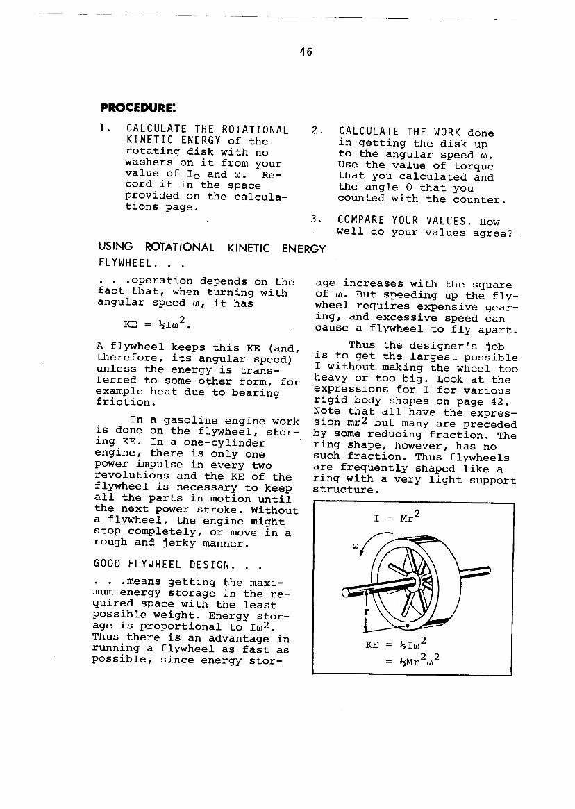
USING ROTATIONAL KINETIC ENERGYFLYWHEEL. ... . .operation depends on thefact that, when turning withangular speed w, it has
KE = ~Iw2.
A flywheel keeps this KE (and,therefore, its angular speed)unless the energy is trans-ferred to some other form, forexample heat due to bearingfriction.
In a gasoline engine workis done on the flywheel, stor-ing KE. In a one-cylinder 'engine, there is only onepower impulse in every tworevolutions and the KE of theflywheel is necessary to keepall the parts in motion untilthe next power stroke. Withouta flywheel, the engine mightstop completely, or move in arough and jerky manner.
GOOD FLYWHEEL DESIGN ... . .means getting the maxi-mum energy storage in the re-quired space with the leastpossible weight. Energy stor-age is proportional to Iw2•Thus there is an advantage inrunning a flywheel as fast aspossible, since energy stor-
2. CALCULATE THE WORK donein getting the disk upto the angular speed w.Use the value of torquethat you calculated andthe angle e that youcounted with the counter.
3. COMPARE YOUR VALUES. Howwell do your values agree?
age increases with the squareof w. But speeding up the fly-wheel requires expensive gear-ing, and excessive speed cancause a flywheel to fly apart.
Thus the designer's jobis to get the largest possibleI without making the wheel tooheavy or too big. Look at theexpressions for I for variousrigid body shapes on page 42.Note that all have the expres-sion mr2 but many are precededby some reducing fraction. Thering shape, however, has nosuch fraction. Thus flywheelsare frequently shaped like aring with a very light supportstructure.
I = Mr2
KE = ~Iw2= ~Mr2w2

Rigid body dynamics isconcerned with the factorscausing changes in rotation-al motions. These includetheir causes, and the natureof the bodies that rotate.
Angular acceleration isthe rate of change of angularspeed:
Angular accelerationresults from the applicationof a torque. Torque, T, isdefined as force times leverarm.
Stalling torque is the tor-que that just prevents amotor from rotating. Dynamictorque is the torque exertedby the motor when it is rota-ting. The two motor torquesare not necessarily the same.
The relation describingchanges in angular speed isthe rotational dynamic equa-tion.
Moment of inertia is thebasic dynamical property of arotating body. It describesthe body's mass and how themass is distributed. Momentof inertia of a single pointmass m at distance r fromaxis is:
For dumbbell shapesand rings, where all themass is at the same radius,the moment of inertia isalso:
I = Mr2•
For other simpleshapes there are otherformulas.
For more complicatedrigid bodies, I can bemeasured. This is doneby observing quantitativelythe effect of a constanttorque as the moment ofinertia is changed by aknown ~I. The formula us-ed is:
The rotational kine-tic energy of a masspoint on a rotator isgiven by:
2 2KE = ~mr w .
The kinetic energyof any rotating rigidbody (of moment of iner-tia I) is:
2KE = ~I,w •

CONVERSION TABLESA NOTE ABOUT UNITS:
On the next page aregiven various units and con-version factors for torqueand moment of inertia. Theserequire some explanation,since the units commonly us-ed in the technical litera-ture (which we call engineer-ing units) are not always theproper absolute units. Abso-lute units must be used incalculations using the rota-tional dynamic equation.
The confusion resultsfrom the difference betweenforce and mass. The table be-low gives the proper forceand mass units for the var-ious unit systems.
Torque has units offorce times length. Thus theproper absolute units aredyne cm, newton meter and
pound feet (or inch ounce) .However, commonly used engin-eering units are gm cm andkg m since gm and kg are oftenused as units of weight.
Moment of inertia hasunits of ~ times lengthsquared. Thus the proper ab-solute units are: gm cm2, kgm2 and slug ft2. However,commonly used engineeringunits are Ib ft2 (or ounce in2)since we rarely use the Englishunit for mass, the slug.
The conversion tables listboth engineering and absoluteunits. Any engineering unitmust be converted to the absoluteunit before making calculationsusing the rotational dynamicequation.
Force = Mass x Acceleration . UnitWeight = Mass x Gravitational Acceleration System
dyne 980 erngramsec2 cgs
(g)
newton kilo- 9.8 m MKS--2(nt) gram sec
(kg)
pound slug 32.2 ft Eng---2(lb) sec lish
If you have a unit in column A and you want a unit in row Bmultiply by the factor shown.
FOR EXAMPLE: If you have 2 and you want Ib in 2 multiplygm cmby:
in23.42 x 10-4 Ib
gm cm2
cm2) 10-4 Ib in2B (lb in2)A(gm x 3.42 x =
gm cm2

49TORQUE
ABSOLUTE UNITS
*dyne em nt m Ib in Ib ft oz in
dyne 1 10-7 -7 -8 -5em 8.85xl0 7.38xl0 1. 42xl0
nt m * 107 1 8.85 .738 142
1b in 1.13xlCP .113 1 .0833 16
Ib ft 7 1. 361.36x10 12 1 192
in 4oz 7.06x10
MOMENT OF INERTIA
ABSOLUTE UNITS2 kg m 2* 1 . 2 sluggm em s ug l.n
2 1 10-7 -5gm em 1.06x10
kg m 2* 107 1 106 .738
slug . 2 4 -3 -3l.n 9.43xl0 9.43xl0 1 6.94xl0
ft2 71.36xl0 144

1. Name three torqueunits.
2. In "Soap Box Derby"races unpowered carsroll down an incline.In coming down thehill, gravity doeswork on the cars andthey receive a defi-nite amount of KEdepending on thechange of height.This KE is shared be-tween the car's lin-ear motion and thewheel's rotation.What kind of wheelswould give the high-est possible finalspeed?
1. The stalling torqueof a small motor(Hurst model CA) isgiven by the manu-facturer as 100 inch-ounces.a) Calculate the tor-
que in Ib ft.b) The motor is con-
nected to a pulleyof one inch radius,and a string iswrapped tightlyaround this pulley.How much weightcould be lifted orsupported by thisstring?
2. The Sigma model 9AK4J2stepping motor is ad-vertized as having ahold torque of 950g cm.This is not a proper
3. In terms of work andenergy, what must bedone to stop a mov-ing car?
4. Explain briefly themeaning of each ofthe four quantitiesin the basic dyna-mic equation.
= I !J.w!J.t
5. Why are record play-er turntables madeof heavy metal ratherthan, say, light,plastic?
unit of torque, sincegrams are units ofmass, not force, Whatis meant is the weightof one gram. Convertthis spec to dyne cm.
3. An engine flywheelhas almost all of itsmass concentrated ina ring at an averagedistance of 15cm fromthe axis of rotation.Its mass is 9000g.Calculate I.
4. A child's playgroundtoy consists of athin, narrow plank,12 feet long pivotedat its center. Themass of the plank is18,000g. A child sitsat each end of theplank. Assume each

child h~s a mass of45,000g.
a) Calculate I forthe plank aboutthe axis at thecenter.
b) Calculate I foreach child aboutthis axis.
c) Calculate the to-tal I for thesame system byadding the threevalues obtainedabove.
d) State briefly howthe childrencould reduce I.
5. A steady torque of 10Ib ft acts on a wheel(free to turn) for 40sec. The wheel startsat rest, and is turn-ing at 1800rpm after40sec. Calculate theKE of the wheel after40sec.
6. A certain "stepping-motor" is advertisedas being able to pro-duce a "step" of pre-cisely 18° rotationin 2.0 millisec. Itis further stated thatthe maximum torqueproduced by the motor
is 3.5 x 10⁵ dyne cm.Calculate the maximumI that the motor can"step" at this rate:
Try the problem insmall steps:a) Calculate the rota-
tion in rad.
b) Calculate the aver-age w during a step.
c) Calculate ~w, as-suming that torqueis constant.
d) Calculate I.
7. A grinding wheel con-sists of a flat disc15 cm in diameter,with a mass of 500gram. It is driven bya motor that exerts aconstant torque of1.3 x 106 dyne cm. Howmuch time is requiredto bring the wheel upto 1725 rpm?
8. A certain flywheelhas KE = lS,OOOft Ibat full speed. Thetorque resultingfrom friction is 75Ib ft. How many rev-olutions will thewheel turn beforecoming to a stop?


PART mDYNAMIC BALANCESTATIC AND
Unbalance not only is extrem-ely annoying but can causeserious destructive effects.The motion of an unbalancedrotor sets up forces thatmake the rotor and its sup-ports vibrate, sometimes vio-lently.
BEARING WEAR:Rotating shafts are supportedin structures called bearings.These are designed to havelow friction, to keep theshaft properly aligned, andto carry the weight of therotating parts. If bearingsare well lubricated and notoverloaded with excess weight,they last a long time, thatis, the metal wears away slow-ly. However, unbalance forcescause rapid wearing away ofmetal and destroy bearingsquickly.
Noise is an obvious result ofvibration; this is because theeffect we call sound is di~rectly produced by vibration.We now know that excessivenoise can be harmful to humanbeings; our hearing can bepermanently demaged and wedo not work efficiently. Evenif these did not happen, anoisy environment is simply anunpleasant place to be.

WHAT IS STATIC BALANCE?It is easy to see when a
wheel mounted on a shaft is inbalance. Turn the wheel gentlyseveral times. Does it alwaysstop with the same point down?or is there no "heavy spot"? Astatically balanced rotorshows no preferred heavy spot;it stops anywhere. This testis useful for getting a roughidea of balance, but it is notvery sensitive.
A better method for alarge, heavy rotor is to placeit on a carefully leveled setof rails. If it shows no ten-dency to roll in any position,it is in static balance.
Most common wheel balanc-ing machines support the wheelby a needle at the center ofits rotation axis. If a bubblethen indicates that the wheelis level, it is staticallybalanced.
This is the method com-monly used with auto wheels.The front wheels, especially,should be statically balancedbecause the reaction forcescan set up an unpleasant, andsometimes dangerous pounding.
CENTER OF MASS:The center of mass (CM)
is a very useful idea in thestudy of dynamics and balance.It is a sort of average posi-tion of a body. It is the pointwhere (for many purposes) themass of a body may be assumedto be concentrated.
How do you find the CM ofa body? First you need to un-derstand the idea of moment,which is a way of describing amass and its position. The mo-ment of a mass is the product
The balancedwheel spins
and whereit stops,
nobodyknows!
A statically baLancedrotor will not rollwhen placed onlevel rai ls .
Static blanceof wheels isa simple pro-cedure.
Dynamic balanceis more com-
plicated.
of the mass and its distancefrom a point.
For exainple, supposeyou have a body made up ofseveral small masses, whereis its CM? The CM is locat-ed at the point where themoments are the same oneither side of it.

The CM is important inbalance because, when a bodyis supported at its CM (by aneedle, say) you know thatthe moments are equal oneither side of the needle. Be-cause of gravity, there areweight forces on the masses.Those weight forces in turnproduce moments of force. Amoment of force is what wehave been calling torque.
When weight torques areequal and opposite, the bodydoes not tend to turn. It isin balance. Because of thisgravitational effect, the CMis more commonly referred toas the center of gravity (CG).
A wheel that is in perfectstatic balance may well vibratewildly when rotating. Somethingis still wrong with it. Thatsomething very often is dynamicunbalance. The explanation ofdynamic unbalance is not simpleand the methods for curing itare not easy.
The problem arises in ro-tating objects that have somethickness. As in static unbal-ance, it is due to an improperdistribution of mass. The massmay be perfectly distributedwith respect to radius but un-equally distributed along theaxis. Thus for objects thathave both diameter and thick-ness, both static and dynamicbalance must be considered.
To dynamically balance arotating object is largelytrial and error. You put onsome additional weights to bal-ance the distribution and seewhether or not you have de-creased the vibration.
Mhen supported at its CM in agravitational field3 all thegravitational torques at work ona body are equal and it remainslevel. Hence CM = CG.
This dynamic duo is in static bal-ance3 but try to spin it and you'rein for troub le.
YOUR EXPERIMENTS:In the final part of
this module you will experi-mently observe the effect ofan unbalanced rotating object,if you haven't already. Thenyou will learn some of thetechniques used to bring suchsystems into static and dy-namic balance.
Later in the module, wewill describe the reasonswhy these techniques worked.

AN EXPERIMENT ........ TO OBSERVE THE EFFECTS OF UNBALANCE •.•.•......
The aim of this first ex-periment is to acquaint youwith the practical effects ofstatic unbalance. First youput the rotor out of balanceby adding one washer and ob-serve its behavior. Then youbalance the rotor approximate-ly by removing the washer, andagain observe the behavior.You will carry out a more pre-cise balancing operation inthe next experiment.
1) Set thevoltage supply at80 volts. Thiswill produce alow rpm so thingsdon't get out ofhand at the start.
2) Mount therotor with onewasher on onebolt. This willproduce an unbal-ance as seen bythe fact that therotor's naturalrest position iswith this boltdown.
3) Turn onthe power supplyand observe thebehavior of thefan and other ob-jects on the ta-ble as the rotorcomes up to speed.
4) Vary therotational speedwith the variable
You cannot measure thevibration quantitiativelyat this point, but the dif-ferences should be obviousand easy to describe inwords.
This experiment is pri-marily exploratory. Theprocedure suggests somethings to do but you shouldinvestigate the cause andeffect of unbalance to yourown satisfaction.
supply and ob-serve the differ-ent vibrationsthat occur. Youshould find thatdifferent speedsproduce largeamplitudes forvarious modes ofvibration of thefan and of otherobjects on thetable.
5) Describewith a sketch atleast three modesof fan vibration,in the data tableat the end ofthese experiments.At what voltagedoes the fan startto "walk"?
6) Explorethe effects ofadding variouswashers at var-ious positions.

In the previous part youobserved the effect of rough-ly balancing a rotor that hadbeen deliberately unbalanced.
Now you will balance thesame rotor carefully using asimple stationary balancingmachine. This particular bal-ancer is designed for balanc-ing rotary lawn mower blades.PROCEDURE:
1) Put 4 washerson one boZt~ 3 on an-other diametricallyopposite. Initiallylocate them at maxi-mum radius.
The rotor should now runwith even less vibration. Youwill see that balance isachieved when you have anequal distribution of momentsabout the axis. This is notthe same as an equal distri-bution of masses.
Follow the general guid-lines below.
2) PZaae therotator on thestatia baZanaeras shown. Thedisk will tiltbecause it isunbalanced.
3) PZaae thespirit ZeveZ on theaenter of the disk.When the level islevel, the bubblewill be within theblack ring asshown.
4) CoarseZy baZanae the disk by ad-justing the radius of the 4 washers. Youprobably cannot do it perfectly. Thisshows, however, that it is not mass alonethat produces static balance.
5) FineZy baZanae the disk by addingsmall pieces of solder. Cut short lengthsand wrap them around bolts. Adjust theirlength until you get as perfectly bal-anced, or level, a disk as you can. Youwill probably have to put pairs ofweights on two adjacent bolts. Clamp thesolder under a nut or washer so it doesnot fly off when rotated.
6) Rotate the disk on thefan and see how well you did.Vary the speed and see if anyresonances occur.
7) Sketah the disk on thedata page. Record the radiusof the two sets of washersfrom the axis.

AN EXPERIMENT ........ TO OBSERVE DYNAMIC UNBALANCE .
Dynamic balance will bediscussed fully in the re-mainder of the text, but nowthe aim is for you to havepractical experience with it.Static unbalance is easy todetect and easy to cure. Bothoperations can be done on asimple balancing machine.
But, dynamic unbalanceis a different story. Dyna-mic unbalance can be detectedonly by a dynamic test, thatis by turning the rotor at
1) Place two iden-tical sets of 4 washerson opposite sides ofthe disk. This changein relative positionsof the masses is a keyfeature of dynamic un-balance. The masses andtheir moments are nolonger in the same planeperpendicular to therotation axis.
2) Statically balancethe disk. Adjust the posi-tion of one (or both)bolts for good static bal-ance. Note that the rever-sal of position does notaffect your ability to getstatic balance.
high speed, and looking forcertain effects. .
Dynamic unbalance canindeed cause severe vibra-tion, but the effect you willlook for here is a slightlydifferent one which we shallcall wobble. The experimentshould help clarify themeaning of wobble, but inbrief it means a motion wherethe plane of the rotor nolonger stays perpendicular tothe axis of rotation.
3) Mount rotoron fan shaft. Dyna-mic unbalance canbe detected andmeasured only by adynamic test.
4) Turn onthe fan at alow voltage(about 70-80volts) •

You have just seen theresults of dynamic unbalance:forces that produce a wobbl-ing motion. The rotor nolonger stays aligned with re-spect to the shaft. If therotor were rigidly attachedto the shaft, these forceswould act on the shaft it-self. Then there would be vi-bration of the whole fan,excessive bearing loads, andother problems.
Our aim here is to see
5) Stop the rota-tion with a strobe.First stop the motionat the highest flashrate that gives asingle image of themark on the rotor.Then change the flashrate slightly so thatthe rotor appears torotate slowly, andyou can see the wobblein "slow motion".
6) Measure wobbleamplitude by "doublingthe flash rate of thestrobe. At twice therpm; you will see thetwo extremes of thewobble. Read the amp-litude along the cmscale on the frame bysighting over theedge of the disc.
7) Sketch the or-ientation of the diskas it rotates in thespace provided in thedata page. Show theposition of the wash-ers.
how the unbalance may be re-moved in this simple specialcase. The key word is counter-weights: masses added so asto keep the moments evenlydistributed in planes perpen-dicular to the axis of rota-tion.
By adding counterweightsthese moments will be in twoplanes rather than the origi-nal one. Of course, when massis added, the static balancemust be checked and preserved.
PROCEDURE:
1) Add 4 washer counterweightsto each of the bolts as shown. Becareful that the two sets of washersin each plane ("upper" and "lower")are arranged in exactly the same waywith respect to nuts, washers, etc.
2) Statically balance the diskin the usual way using the staticbalancer. Keep the bolts near theirmaximum radius.
3) Dynamically measure and re-cord the wobble amplitude with thestrobe as on the preceding page.
When an object ,is out of dynamicbalance this method of adding counter-weights is the procedure for bringingit back into balance. Unfortunatelythe decision of how much to add andwhere to put them is not clear andgenerally must be done by trial anderror. In the final experiment you willsee a standard method that is compli-cated but works.

Dynamic unbalance is acommon effect, particularlywith thick or long rotors,such as electric motor arma-tures, or crank-shafts. It isalmost never obvious wheremass should be added or howmuch. Modern automobile plantsuse sophisticated automaticmachinery to balance crank-shafts. But thls lab is con-cerned with a simple device
1) Mount the dynamicaLLyunbaLanced disk securely onthe fan shaft. There shouldbe no washers or other weightsattached to the disk.
2) Mount the fan on thefLexibLe tabLe. Be sure thefan is seated in the slot inthe table. Wing nuts shouldbe tightened securely. Checkthat the table bounces freelywithout binding or hittingstops.
3) Turn on the fan andadjust the speed to thenatural resonant bouncingfrequency of the table. Itis important that you achievemaximum amplitude of vibra-tion since this amplitudewill be your reference forlater improvement.
Record the ampLitude.
4) Add a washer to eachof two opposing boLts. As inthe previous experiment youshould put one on one sideand one on the other side of
and a simple procedure formeasuring and correctingdynamic unbalance on almostany rotor.
A symmetric, but dynam-icaLLy unbaLanced disk isprovided. Your task is toadd weights at the properplaces to bring it into dy-namic as well as static bal-ance.
the disk to retain staticbalance.
5) Turn on the fan andmeasure the bouncing ampLi-tude. The voltage for maxi-mum amplitude should nothave changed much but youmight have to adjust itslightly.
Has the amplitudedecreased?
6) Move and trim themass untiL the bounce ampLi-tude is zero. If the ampli-tude is greater try the nextbolt. If the amplitude issmaller, try more washers onthe same bolt. Keep tryingvarious combinations untilthe amplitude is zero. Thesecret is to avoid boltsthat make the vibration worse,stay with those that improveit. Be sure the disk is instatic balance.
7) Sketch disk and re-cord masses added on thedata sheet.

Mount the fanon the dynamicbalancing table.
If the amplitude is:
Large ~
f Smaller
DYNAMICBALANCE


THE EFFECTS OF UNBALANCE (Description and sketch of 3 modesof fan vibration)

DYNAMIC UNBALANCE (Sketch of orientation of unbalanced diskin rotation showing washers and positions)
FLEXIBLE TABLE BALANCER (Sketch of disk showing masses addedand their position relative to referencemarks)

STATIC UNBALANCEUNBALANCED FORCES IN ROTATION:
Our purpose is to describethe cause of static unbalance,and how it leads to vibrations.From this description it willthen be clear what steps can be
Suppose a point mass m ona rotor is moving with rota-tional speed w. You know fromNewton's first law that themass wants to keep moving in astraight line at speed v = rw.To make the mass rotate aspart of the rotor requires aninward force. This force iscalled a aentripetal forae andalways acts radially inward.The magnitude of this forcecan be derived (see optionalsection on the next page), andis found to be:
Fc2= mrw
The Centripetal Foraeon a Mass Point.
This inward centripetalforce, of course, must be ex-erted by something. In thesimple case of a weight on theend of a chain, it is exertedby your arm. For a mass rotat-ing on bearings, it is thebearings that must exert theforce.
According to Newton'sthird law, if the bearing ex-erts a force on the shaft, itfeels an equal and oppositeforce. This force is calledthe reaation forae, Fr. Its
taken to cure the problem.Vibrations are caused byforces. Thus the firststep is to understand whatforces are presented.
Fe - mrw2The aentrip'etalforae is radi""aU irDJJara.
Fc~
The reaationforae is radiallyoutward.
magnitude is equal to the 2centripetal force Fr=Fc=mrwand its direction isradially outward on thebearing.

2Fe • mrw
The relation for thecentripetal force on a rota-ting mass, m, can be mathe-matically derived. As in thederivation in Part I we willconsider what happens to themass during a small time in-terval, ~t. Referring to thediagram, we assume that dur-ing ~t, the mass moves froma to b through a small angle~e.
The linear velocity, v,at a and b is of the samemagnitude, rw, but in a dif-ferent direction. Since ve-locity is a vector quantitya small additional velocity,~v, must have been added toproduce the direction change.From Newton's laws we knowthat velocity changes areproduced by forces. From thelinear dynamic equation wehave:
~vF = m ~t.
The value of v can be de-termined by referring to thevector addition geometry. Theangle between va and Vb isalso ~e so that:
~v ~ v~e,where we assume that if ~e issmall, ~v is nearly equal tothe arc. From the top diagramwe see that:
~s~e = -rPutting this into the
previous expression we get:~v = v ~s.
r
~v = additionaZ veZocityrequired to produce direc-tion change.
Putting this into theforce equation gives:
v ~sF = m r ~t·
~sBut ~t = v so that:v2
F=m-r
And since v = rwwe have:
F 2= mrw •cThe direction of
Fc is the same as ~v,which is radially in-ward.

The center of mass of abody is defined as that pointabout whick all the momentsare equally distributed. Arotational moment is simplythe product mr of a mass mat radius r.
Begins to have meaningif one assumes the body tobe in a gravitational field.Then there is a force on eachmass point of mg. And if thepoint can only rotate about afixed axis then the force be-comes a torque of mrg (pro-vided r = rJ.).
Thus the rotationalcenter of mass is that pointabout which the net gravita-tional torque is zero; andthe center of mass is iden-tical to the center of gra-vity.
On the previous page wesaw that the reaction forceon a rotating point mass wasmrw2. This is simply the mo-ment (mr) times the square ofthe angular speed.
If a body rotates aboutits center of mass, these mo-ments are equally distributed.Thus the reaction force ofeach mass point has an iden-tical opposing reaction forceon the opposite side of therotation axis. The result isno net reaction force on thebearings provided that thebody rotates about its centerof mass.
CENTER OF MASS all rota-tional moments balance.
CENTER OF GRAVITY allgravitational torquesbalance.
ROTATION ABOUT CENTEROF MASS all reactionforces balance.
Thus the key to staticbalance is to be sure thatthe body rotates about thecenter of mass ••••or viceversa ••••be sure that thecenter of mass is at theaxis of rotation.

When a body rotates aboutan axis that is not throughthe center of mass, the reac-tion forces on the bearings donot all balance out. There aregreater rotational moments onone side than the other. Andthere is a net reaction forceon the bearing that rotateswith the angular speed, pull-ing on the bearing as it goes.
The size of this net re-action force is simple to cal-culate. The body acts as ifall of its mass, M, were con-centrated at the center ofmass at rotational radius, r,the distance between the eMand the axis of rotation. Thusthe unbaZanced reaction forceon the bearing is:
F = Mrw2•r
While r is generallyquite small, sometimes onlythousandths of an inch, M isthe whole mass of the bodyand Fr can get quite large,particularly at large w.
. A real machine, like thefan, has several preferreddirections in which it likesto vibrate. These modes of vi-bration have certain naturalfrequencies much like the vi-brating reed. The directionof these natural modes can beat any angle.
When the disk rotates,the unbalanced force rotatesaround with it at the rota-tion frequency. The componentof Fr in any direction oscil-lates back and forth at thisfrequency. Thus if w exactlymatches the natural frequency
When the center of mass isnot at the center of rotation,the net reaction force on thebearings is: Fr = Mrw2
As the body rotates, thenet reaction force on the bear-ings rotates with it.
;\"
II~~I
I
The component of Fr in anydirection osciZZates at w andwiU excite any naturaZ modesat that frequency.
of a particular mode, itwill act like a drivingforce in that direction andcause that mode to oscillatestrongly.
This condition is call-ed resonance. Different ang-ular speeds will, of course,excite different vibrationalmodes of the fan, just asyou observed in your experi-ment.

THE CURE FOR STATIC UNBALANCE ...As is obvious by now, the
cure for static unbalance isto be sure that the rotationaxis of a body coincides withthe center of mass. While itis often difficult to move therotation axis, it is generallynot difficult to move the cen-ter of mass.
A rotor on its shaft cangive a rough idea in whichdirection the center of massis shifted since it pulls thatside down. It is only a roughindication however since mostbearings have significant sta-tic friction.
A considerably more sen-sitive method is to suspendthe body horizontally at itsaxis by a needle bearing, asyou did with the static bal-ancing machine. Do you see whythis is equivalent to a ver-tical suspension?
Sometimes it happens thatyou cannot get at the rotatingsystem to balance it. For ex-ample the rotor of the fanmotor may be out of balanceeven though the disk is per-fectly balanced. At some ang-ular speed a strong, unwantedvibration resonance may occur.What can you do? There arethree choices:
1. Change the angular speedso that the unbalancedreaction force no longerdrives the vibration atits resonant frequency.Often this is not possiblehowever.
2. Change the resonant fre-quency. This can often bedone by mounting the sy-
rotation.-axis
eWhen an unbalanced disk is sus-pended vertically, the force ofgravity pulls the center of massdoum.
needle bearing,'
A more sensitive method is tosuspend it horizontally at thecenter of rotation on a deli-cate needle bearing. An offazis CM will show up as a tilt.
Mounting on aheavy baseshifts reso-nant frequency.
Friction mountabsorbs energyof vibration.
stern on a heavier base,that is change its mass.
3. Mount the machine onsome kind of dampingmount that absorbsthe energy of vibra-tion by friction.This prevents the amp-litude of vibrationfrom building up.

DYNAMIC UNBALANCEUNBALANCED TORQUE IN ROTATION:
To explain static unbal-ance we looked at the forcespresent and how they acted onthe bearings. To explain dy-namic unbalance it is neces-sary to determine if theseforces produce any torques.
The rotor on the fan wasa thin disk, almost a singleplane. When it rotated, thisplane was perpendicular tothe rotation axis. All thereaction force lay in theplane of the disk and were al-so perpendicular to the axis.When you added washers to thedisk, particularly when youadded them to opposite sides,you began to give the diskthickness. With thickness, theanalysis changes.
REACTION FORCES ...Consider the thin disk
with two equal masses maddedat equal radii r, but on op-posite sides of the disk. Atangular speed w the reactionforces on these masses areboth mrw2. But, the reactionforces do not act along thesame line, that is at the samepoint on the axis.
... PRODUCE WOBBLE TORQUES:. They are separated by a
d~stance 2d. Two forces likethese are sometimes called acouple. This couple clearlyproduces a torque whose magni-tude is:
'T = 2mrw2d.This torque tries to twistthe disc out of its normalperpendicular position, caus-ing it to wobble as it turns.
The disc in your experi-ment was flexible so it bent
The dynamically unbalanceddisk was seen to flex and wobble.If the disk were rigid, the wob-ble torque would all act on themotor bearings.
IIlrI I
d I I
II II II II
FrWobb le torque:
to adopt a tilted positionas it turned. (Check yoursketch of the dynamic unbal-ance experiment.) If thebody were more rigid, thenit would not bend. Insteadthe wobble torque would betransmitted to the rotatio-nal shaft and bearings toproduce strain, wear, andvibration.

THE CURE FOR DYNAMIC UNBALANCE:To eliminate dynamic un-
balance one must either redis-tribute the mass of the rotorso that no couples exist, oradd couples that are equaland opposite to the ones thatare present.
Adding a couple means toadd a pair of weights (to pre-serve static balance) on op-posite ends of a diameter andon opposite sides of the rotor.
In your first experimentson dynamic unbalance, eithersolution was clearcut sincethe unbalanced masses werelarge, you could see wherethey were, and you could eas-ily move them. In your lastexperiment, as with most rota-ting bodies, the unequal dis-tribution of mass was neitherknown or could it be moved.Thus a trial and error proce-dure had to be adopted to at-tempt to improve the problem.
Simple, dynamically unbalancedcrankshaft of a 1950 Model AFord, a slow turning engines ...
Complex, dynamically balancedcrankshaft of a modern highspeed V-B.
A dynamically unbalance canbe balanced by ...
... redistributingthe mass along theaxis or ....
.... by addingequal masseson oppositeaides of therotor.
SOME EXAMPLES:Dynamic unbalance oc-
curs most often in thickrotors, rotors that extendalong the axis for some dis-tance (d large), for ex-ample, tires, motor arma-tures and engine crankshafts.Unbalance effects increasewith the square of the ang-ular speed, so that crank-shaft balance is of greatimportance in racing andhigh performance enginesthat turn at ,high speed.
There are many differ-ent techniques that are usedto dynamically balance rota-ting bodies. In general eachspecific balancing problemleads to a specific tech-nique to help reduce theguesswork. On the next pageare a couple of examples ofways to reduce the number oftrials and minimize the er-rors.

Static balancers are es-sentially the same as the de-vice you used to staticallybalance the disk. They areeasy to use and are effectivein most cases.
Auto wheels, especiallyfront wheels, should be sta-tically balanced. But widetires, as any thick rotor,can be dynamically unbalanced,even though statically bal-anced. In fact, carelessplacement of static balancingweights may actually causedynamic unbalance.
Automobile dynamic wheelbalancers are essentiallywobble detectors. The wheelis driven at high speed by anelectric motor and the wobbleamplitude is observed. Onetechnique is to mount a smallprobe near the rim. As thewheel wobbles, the positionof the probe, when the tirejust strikes it, measures thewobble amplitude. The probecan be used to trigger astrobe and thus indicate wheremasses should be added on thewheel.
LARGE ROTORS:The dynamic balancing of
large rotors, such as largegenerator armatures, is essen-tial if they are to run athigh speeds. There is a fairlystandard procedure that isfollowed for such rotors, pro-vided you can get at both endsto add or remove mass. It
Static wheeZ baZancing issimpZe. . . .
. . . .but dynamic wheeZbaZancing requires com-pZicated equipment andgood judgement.
utilizes a flexible table muchlike the one you used but theprocedure is somewhat differ-ent. The procedure results inboth static and dynamic bal-ance of the rotor. On the nextpage this balancing procedureis illustrated.

The rotating machine ismounted on a flexible tableas shown. The table is mount-ed on two sets of springs. Itcan be pivoted about eitherof two axes. This arrangementhas a resonant frequency ofvibration and the amplitudecan become large when theangular speed equals thisfrequency.
Step I consists in put-ting a shaft through I sothat the table can pivot a-bout that axis. The right endis then free to vibrate onthe spring. The rotor is runand its speed is adjusted formaximum vibration amplitude -resonance. The rotor is stop-ped and mass is added any-where on the right end plane.It is then run again, and thenew vibration amplitude ob-served. Again it is stopped,the mass is moved one quarterturn around the rotor, andthe vibration amplitude ob-served. This trial and errorprocedure is repeated untilthe vibration amplitude hasbeen reduced to zero.
Adding only one mass hasobviously statically unbalanc-ed the rotor. Clearly thismust be a two-step process.
In step 2 a shaft is putthrough the right hand tableaxis. The table now pivotsabout this, and vibrates atthe left end. Note that thisstep is necessary in order toachieve both static and dynam-ic balance. The same trial anderror procedure is repeatedas before, masses being addedto the left end plane. Theobject is again to reduce the
The motor used to spin the rotorat the resonant bouncing fre-quency of the table is not shown~
~freevibration
Weights are added by trial anderror to the right end of therotor until the vibration amp-litude is reduced to zero.
Weights are then added to theleft end of the rotor. When theamplitude is zero, the rotor isboth statically and dynamicallybalanced.the vibration amplitude tozero.
Although the detailsare complicated, the basicidea of this procedure issimple. The table is a vi-bration amplifier that in-creases the vibration ampli-tude. By eliminating allvibrations you remove thereaction forces and thewobble torques.

Static and dynamic bal-ance are important becauseunbalance can cause vibrationand unnecessary large forceson bearings and moving parts.These lead to noise, rapidwear and breakdown.
Mass points on rotatingbodies are acted on by centri-petal forces. These act ra-dially inward and are neces-sary to deflect the massesinto circular paths. Theforces are transmitted to themass points by the rotor. Butthey must corne from the rotorshaft and bearings. By New-ton's third law there is anoutward reaction force on theshaft and bearings. For eachmass point this outward reac-tion force has magnitude.
2= mrw .
With a statically balanc-ed rotor (one spinning aboutits CM) the net reaction forceis zero. When a rotor is notstatically balanced, the netreaction force is not zero.This force continually chang-es direction as the rotorturns. It puts strain on therotor and bearings and cancause strong vibrations, par-ticularly if the angularspeed is the same as a fre-quency of natural vibrationof the system.
Static balance existswhen an object, supported atits center of mass, has notendency to turn. That is, thenet gravitational torque iszero. When rotating on the CM
as axis, the rotor turnssmoothly, without vibration.
Static unblance is cor-rected by adding masses ata position diametricallyopposite to the CM. Staticbalancing machines use alevel to indicate when theCM is at the point of sup-port.
Degree of unbalancedepends on the position ofthe CM with respect to theaxis. The reaction force onthe bearings is given by:
2Ff = Mrw ,
where M is the total massof the rotor and r is theseparation of the rotationalaxis and the CM.
Dynamic unbalance oc-curs when two masses on arotor are located at twodifferent points along theaxis. The reaction forceson the two masses form acouple that results in atorque. This torque tendsto make the rotor and theshaft wobble about an axisperpendicular to the rota-tion axis.
Dynamicunblance iscorrected by adding pairsof masses in two planesseparated along the axis.Pairs of mass are neededto maintain static bal-ance.

1. Suppose you cannot addmasses to a staticallyunbalanced rotor, butwere permitted to drillholes in it. What wouldyou do to achieve bal-ance?
2. State several impor-tant properties of CM.
3. The angular speed of anunbalanced rotor in-creased from 1000rpm to2000rpm. How much areunbalance effects in-creased?
A certian rotor has amass of 10kgi its CMis lcm from the axis.Where should you placea O.lkg weight?
A certain rotor con-sists of a very lightrod 10cm long with a2kg mass on the endof it. The light rodalso extends in thediametrically oppositedirection. You have a200g mass. Could youbalance this rotor?How?
4. Could you have dy-n~"ic unbalance ina rotor made in theshape of a thinflat disk? Explain.
S. Can you suggest areason why v-aengines are nowthe most common,having completelyreplaced straighteights and evenmost sixes?
A rotor has a totalmass of Skg and itsCM is lcm from theaxis. What is thereaction force onthe bearings at3000 rev/min?
The bearings on acertain rotor canwithstand safely areaction force oflOOnt, about 201b.The rotor has amass of IOkg andthe eM is lmm fromthe axis. How fastcan the rotor turn?
Dynamic unbalanceresults from twolOOg masses at aradius of 30cm.They are separatedalong the axis by2cm. Calculate thewobble torque at300 rad/sec.