Module A Adjustment B 2019-01-0597 Protection and Z ...
8
Page 1 of 8 12/20/2018 2019-01-0597 Development of an Advanced Motor Control System for Electric Vehicles Abstract Electric vehicles are considered as one of the most popular way to decrease the consumption of petroleum resources and reduce environmental pollutions. Motor control system is one of the most important part of electric vehicles. It includes power supply module, IGBT driver, digital signal processing (DSP) controller, protection adjustment module, and resolver to digital convertor. To implement the control strategies on motor control system, a lot of practical aspects need to be taken into accounts. It includes setup of the initial excitation current, consistency of current between motor and program code, over-modulation, field weakening control, current protection, and so on. In this paper, an induction motor control system for electric vehicles is developed based on DSP. The control strategy is based on the field-oriented control (FOC) and space vector pulse width modulation (SVPWM). Speed calculation, over-modulation, field weakening control, PI controller, and fault diagnosis are also applied in this DSP algorithm. As an industry product running on a real electric bus with a 100kW induction motor, communication with vehicle control unit (VCU) by CAN bus, control system safety and PC software designed for lab experiments are also discussed. This paper focused on how to develop the advanced motor control system for electric vehicles for industrial application. The steady-state and transient performances of this motor control system are analyzed by both test-bench experiments and road experiments. Its performance is satisfactory when applied to the real electric vehicle. Introduction Recently, electric vehicles have been promoted as a practical platform for reducing environmental pollution and mitigating energy crisis. Vehicle control unit (VCU), motor control system (MCU), and battery management system (BMS) are the main control systems of electric vehicles. Other technologies of electric vehicle include the motor design, body and chassis design, battery design, and particularly the system-level design and optimization of electric motor drive systems [1, 2, 3]. Motor control system plays a very important role in driver safety and comfort. Induction motors (IMs) are widely used for electric vehicles due to their simple structure, good performance, and low cost [4, 5, 6]. As for the control methods for IM, there are the V/F control, field oriented control (FOC), direct torque control (DTC) and some modern control methods, like model predictive control (MPC), fuzzy control, and neural networks. However, for industrial products of electric vehicles, FOC appears to be the most popular control strategy [7, 8]. This paper is focused on how to develop the induction motor advanced control system for electric vehicles based on DSP. Apart from the implementation of FOC and SVPWM, some practical problems, such as current protection, over-modulation and field weakening control method are all discussed and the performance of final control strategy is verified on a real electric bus. This paper shows some aspects, which need to be taken into account when developing motor control methods on digital control chips, like DSP, for industrial application. It will do some help for applying new control methods like MPC on industrial motor to achieve better performance. DC Baterry Power Supply Module IGBT Driver Auxiliary Power DSP Controller Protection and Adjustment Module AC Motor U V W Resolver to Digital Convertor Temp. Sensor Volt. Sensor Current Sensor CAN Communation External I/Os Z A B Control Signals Figure 1. Diagram of motor control system. Construction of Motor Control System Basic Diagram of the System Figure 1 shows the diagram of the motor control system. The motor control system of electric vehicle includes the power supply module, IGBT driver, DSP controller, protection and adjustment module, and resolver to digital convertor. The power source of this electric bus is a 650V battery set. It supplies voltage to IGBT driver and converts it to various voltage power source as required for other parts of motor control system. IGBT module receives instructions from DSP controller and produces balanced three phase voltage (U V W) to drive the induction motor. It also collects the temperature, voltage and current signals and then transfers them to the DSP controller via protection and adjustment module. Resolver to digital convertor detects the motor speed with direction and then produces three corresponding signals (A B Z) and transfers them to DSP for speed
Transcript of Module A Adjustment B 2019-01-0597 Protection and Z ...

Page 1 of 8
12/20/2018
2019-01-0597
Development of an Advanced Motor Control System for Electric Vehicles
Abstract
Electric vehicles are considered as one of the most popular way to
decrease the consumption of petroleum resources and reduce
environmental pollutions. Motor control system is one of the most
important part of electric vehicles. It includes power supply module,
IGBT driver, digital signal processing (DSP) controller, protection
adjustment module, and resolver to digital convertor. To implement
the control strategies on motor control system, a lot of practical
aspects need to be taken into accounts. It includes setup of the initial
excitation current, consistency of current between motor and program
code, over-modulation, field weakening control, current protection,
and so on. In this paper, an induction motor control system for
electric vehicles is developed based on DSP. The control strategy is
based on the field-oriented control (FOC) and space vector pulse
width modulation (SVPWM). Speed calculation, over-modulation,
field weakening control, PI controller, and fault diagnosis are also
applied in this DSP algorithm. As an industry product running on a
real electric bus with a 100kW induction motor, communication with
vehicle control unit (VCU) by CAN bus, control system safety and
PC software designed for lab experiments are also discussed. This
paper focused on how to develop the advanced motor control system
for electric vehicles for industrial application. The steady-state and
transient performances of this motor control system are analyzed by
both test-bench experiments and road experiments. Its performance is
satisfactory when applied to the real electric vehicle.
Introduction
Recently, electric vehicles have been promoted as a practical
platform for reducing environmental pollution and mitigating energy
crisis. Vehicle control unit (VCU), motor control system (MCU), and
battery management system (BMS) are the main control systems of
electric vehicles. Other technologies of electric vehicle include the
motor design, body and chassis design, battery design, and
particularly the system-level design and optimization of electric
motor drive systems [1, 2, 3].
Motor control system plays a very important role in driver safety and
comfort. Induction motors (IMs) are widely used for electric vehicles
due to their simple structure, good performance, and low cost [4, 5,
6]. As for the control methods for IM, there are the V/F control, field
oriented control (FOC), direct torque control (DTC) and some
modern control methods, like model predictive control (MPC), fuzzy
control, and neural networks. However, for industrial products of
electric vehicles, FOC appears to be the most popular control strategy
[7, 8].
This paper is focused on how to develop the induction motor
advanced control system for electric vehicles based on DSP. Apart
from the implementation of FOC and SVPWM, some practical
problems, such as current protection, over-modulation and field
weakening control method are all discussed and the performance of
final control strategy is verified on a real electric bus. This paper
shows some aspects, which need to be taken into account when
developing motor control methods on digital control chips, like DSP,
for industrial application. It will do some help for applying new
control methods like MPC on industrial motor to achieve better
performance.
DC Baterry
Power Supply Module
IGBT Driver
Auxiliary Power
DSP Controller
Protection and Adjustment
Module
AC Motor
U
V
W
Resolver to Digital
Convertor
Temp. Sensor
Volt. Sensor
Current Sensor
CAN CommunationExternal I/Os
Z
AB
Control Signals
Figure 1. Diagram of motor control system.
Construction of Motor Control System
Basic Diagram of the System
Figure 1 shows the diagram of the motor control system. The motor
control system of electric vehicle includes the power supply module,
IGBT driver, DSP controller, protection and adjustment module, and
resolver to digital convertor. The power source of this electric bus is
a 650V battery set. It supplies voltage to IGBT driver and converts it
to various voltage power source as required for other parts of motor
control system. IGBT module receives instructions from DSP
controller and produces balanced three phase voltage (U V W) to
drive the induction motor. It also collects the temperature, voltage
and current signals and then transfers them to the DSP controller via
protection and adjustment module. Resolver to digital convertor
detects the motor speed with direction and then produces three
corresponding signals (A B Z) and transfers them to DSP for speed
Page 2 of 8
12/20/2018
calculation. Signals A and B are two square wave signals with 90
electrical degrees out of phase, which contain the data of motor
speed. Signal Z is the signal of speed direction. DSP controller
communicates with vehicle controller using CAN bus. It produces the
motor drive PWM signals based on FOC and SVPWM algorithm and
sends them to IGBT driver and thus drives motors. The DSP
TMS320F28335 is used in the test-bench experiments and a real bus
motor control system. Its high performance is quite appropriate for
motor control system [9].
Hardware of the System
Basic Requirements
1. The hardware system has excellent hardware safety. It has the
capability of measuring bus voltage, phase current and system
temperature. It has quick responds to over voltage error, over
current error, over temperature error, phase lost and other
running errors. When error happens, it will turn off IGBT and
decrease the motor speed to stop the electric vehicle.
2. The hardware system has good electromagnetic compatibility
(EMC). It has a nice control of electromagnetic interference
(EMI) so that unwanted effects are prevented when the electric
vehicle is running in a complex condition.
3. It supports CAN bus and 485 ports. The system is composed of
several functional packages and easily to be adjusted to fit for
other systems.
4. The system is stable for complex environments. It survives
between -40℃ and 125℃ and its shell is waterproof.
CPU Module
TMS320F28335 is a 32-bit floating-point processor, which is
produced by Texas Instruments (TI). It has six enhanced PWM
modules, two enhanced quadrature encoder pulse (QEP) modules,
one Enhanced analog-to-digital converter (ADC) module with sixteen
channels, two enhanced controller area network (eCAN) modules,
three serial communications interface modules, one serial peripheral
interface (SPI) module and abundant on-chip memory [9]. It is
Harvard bus architecture and its operating frequency is up to
150MHz. Its high performance is quite well for the motor control
system.
Power Supply Module
Battery voltage is transformed to 15V, 24V and 5V system voltage by
specialized convertor. F28335 needs 3.3V as I/O output voltage and
1.8V as digital parts supply voltage. The voltage is acquired by
voltage management chip AZ1117D. AD convertor reference voltage
is 1.25V and it is obtained by PWM output of DSP.
IGBT Driver
The IGBT driver is designed on a separate PCB board. This kind of
design is convenient for adjusting circuit for power need of different
system. The FF400RKE3 is used as IGBT and M57962AL is used for
IGBT driver. As for IGBT FF400RKE3, DC forward current is 400A,
gate threshold voltage is 5.8V, turn-on delay time is 0.25us, turn-off
delay time is 0.5us. IGBT driver M57962AL has two voltage supply
topology, its output voltage works at 15V for IGBT gate.
Phase Current and Voltage Measurement
Phase current is acquired by current transducer HAT500-S from
LEM. Its supply voltage is ±15V and it has accuracy about 1%,
which is good enough for phase current measurement. Voltage is
acquired by ADC of DSP through adjustment circuit from phase
current. The max value of ADC for current and voltage are 1273.5A
and 963V respectively in this system.
Speed Measurement
The speed is measured by QEP of DSP and resolver to digital
converter AU6802. Smart-coder AU6802 converts the electrical
information, which is corresponding to a mechanical rotational angle
of the resolver, to a digital signal and send it to DSP. The output of
AU6802 could be set as pulse output and parallel absolute output.
Parallel output has two mode, parallel bus interface mode and parallel
I/O interface mode. In this system, it is set as pulse output mode.
QEP module supports low speed measurement with capture unit and
high speed measurement with a 32-bit unit timer.
Implementation of Algorithm
Scheme of FOC for AC IM
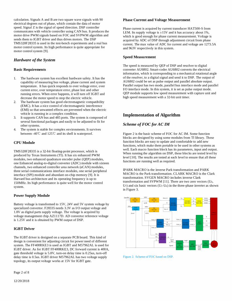
Figure 2 is the basic scheme of FOC for AC IM. Some function
blocks are designed by using some modules from TI library. These
function blocks are easy to update and comfortable to add new
functions, which make them portable to be used in other systems as
well. Each macro function block has its parameters, input and output.
When running the algorithm on DSP, these blocks are tested level by
level [10]. The results are tested at each level to ensure that all these
functions are running well as required.
IPARK MACRO is the inverse Park transformation and PARK
MACRO is the Park transformation. CLARK MACRO is the Clark
transformation. SVGEN MACRO includes inverse Clark
transformation and SVPWM [11]. There are two zero vectors (U0,
U7) and six basic vectors (U1-U6) in the three-phase inverter as shown
in Figure 3.
3-Phase
Inverter
PID
MACRO
Spd
CURMOD
MACRO
PID
MACRO
Iq
PID
MACRO
Id
IPARK
MACRO
SVGEN
MACRO
PWM
MACRO
PARK
MACROCLARK
MACRO
ADC
CONV
ACI
MotorSPEED
FR
MACRO
QEP
MACRO
SpeedRef
IdSet
IqRef
IqFdb
IdFdb
Park_D
Park_Q
IQs
IDs
iPark_D
iPark_Q
θ
θ
θ
Uβ
Uα
Ta
Tb
Tc
Speed
Speed
Rpm
QepA
QepB
Index
Direction
Angle
Ia
Ib
Vdc
Clark_a
Clark_b
Park_d
Park_q
Clark_d
Clark_q
ω
Field
Weaken
Speed
IdRef
PWMA
PWMB
PWMC
R/D
converter
Figure 2. Scheme of FOC based on DSP.

Page 3 of 8
12/20/2018
Giving 𝑈𝛼and 𝑈𝛽, one can have a 𝑈𝑟𝑒𝑓 as input, which can be equally
obtained from two of the six basic vectors. In the DSP program, it is
needed to acquire the PWM durations T1 and T2 of the two
corresponding basic vectors. Therefore, one has to know in which
sector the 𝑈𝑟𝑒𝑓 is located for acquiring the correct duration. To find
out the correct sector, three variables, 𝑉𝑟𝑒𝑓1, 𝑉𝑟𝑒𝑓2, 𝑉𝑟𝑒𝑓3 are used.
𝑉𝑟𝑒𝑓1 = 𝑈𝛽 (1)
𝑉𝑟𝑒𝑓2 =−𝑈𝛽+√3𝑈𝛼
2 (2)
𝑉𝑟𝑒𝑓3 =−𝑈𝛽−√3𝑈𝛼
2 (3)
If 𝑉𝑟𝑒𝑓1 > 0 then a=1, else a=0. If 𝑉𝑟𝑒𝑓2 > 0 then b=1, else b=0. If
𝑉𝑟𝑒𝑓3 > 0 then c=1, else c=0;
The sector is defined as, sector=4*c+2*b+a. According to this, the
correct sector, in which the 𝑈𝑟𝑒𝑓 is located, can be worked out. As to
the duration, it can be found out that there are only three basic values
for calculating in all the possible occasions. Variables X, Y, Z are
used here to calculate the final duration, where
X = 𝑈𝛽 (4)
Y =1
2(√3𝑈𝛼 + 𝑈𝛽) (5)
Z =1
2(−√3𝑈𝛼 + 𝑈𝛽) (6)
Then the duration table can be obtained as table 1 shows. As
implementation is based on DSP, one should use the related registers
to get the trigger value and thus one can get the expected PWM for
motor drive [7].
QEP MACRO and SPEED FR MACRO are the parts of calculation
of motor speed. CURMOD MACRO is the current module. It uses
the motor speed to calculate the electrical angle, which is needed for
Park transformation and inverse Park transformation. PID MACRO is
the PID control unit. It plays a great role in the transient and steady-
state performance of the control system.
U1 (001)
U6 (101)
U2 (011)U3 (010)
U5 (100)
U4 (110) U0(000)U7(111)
Uref
β
11
S
TU
T
22
S
TU
T
αθ
6
4
5
1
3
2
Figure 3. SVPWM scheme: U1-U6 are the basic vectors, U0 and U7 are the zero vectors, and Ts is the control period.
Table 1. Duration select table
Sector 3 1 5 4 6 2
Vector U1,
U2
U3,
U2
U3,
U4
U5,
U4
U5,
U6
U1,
U6
t1 -Z Z X -X -Y Y
t2 X Y -Y Z -Z -X
Initial QEP module
Call QEP_MACRO
UPEVNT
YES
Calculate ΔT
UTO
YES
Calculate ΔX
Transfer
QEP_MACRO’s parameters to SPEED_MACRO
NO
ΔT and ΔX not change
NO
Use equation
X/ΔT
Use equation
ΔX/T
Adjust the two answer with certain
principles
Adjust speed direction according to vehicle direction
end
start
Figure 4. Speed calculation flow diagram
Speed Calculation Algorithm
Speed measurement is a very important value for the FOC algorithm.
The current module needs the value of speed to estimate the flux
angle while Park transformation and Clark transformation need the

Page 4 of 8
12/20/2018
flux angle to do calculation. The speed measurement equations are
shown as (7) and (8).
v L(k) =𝑋
𝑡(𝑘)−𝑡(𝑘−1)=
𝑋
∆𝑇 (7)
v𝐻(k) =𝑥(𝑘)−𝑥(𝑘−1)
𝑇=
∆𝑋
𝑇 (8)
where
X: Unit position defined by integer multiple of quadrature edges
ΔT: Elapsed time between unit position events
Δx: Incremental position movement in unit time
T: Unit time
Equation (7) is used for low speed measurement and equation (8) is
for high speed measurement. Final speed used in algorithm is derived
from a combination of this two methods. Speed calculation flow is
shown as figure 4.
DSP Algorithm
The FOC is implemented on DSP and it is the major part of the motor
control system for electric vehicle. Its control frequency is actually
based on the PWM interrupt service frequency. In addition to the
main FOC algorithm, over-modulation, field weakening control, the
system protection, error detection, communication with PC and
vehicle control unit, and other aspects, are also considered [12].
The main program flow diagram is shown in Figure 5. When the
motor control system starts, the system clock and GPIO are
initialized by function DeviceInit(). MemCopy() moves MainISR to
RAM from flash to save running time. GetSysPara() is the function of
reading parameters from FRAM, which is based on protocol I2C.
These parameters include the motor parameters and some parameters
for communication between DSP and PC. Three tasks are always
running in the background loop. The FOC control algorithm runs in
PWM interruption service function program (PWM_ISR) and
FAULT_ISR deals with all the error diagnose work. When the
system detects some errors in running state, the protection action will
be triggered and the motor speed will decelerate gradually and then
the motor will shut down in the end. Errors will be uploaded to the
vehicle control unit or PC for further analysis. The PWMISR
program flow diagram is shown in Figure 6. The modules mentioned
in the FOC scheme are used in this program. PWM signals are
produced as required by these program.
As this development is based on DSP and used for electric vehicles,
some work about electric vehicle also needs to be accomplished.
Three tasks in background loop are used to deal with the following
problems. AD sampling, temperature and battery voltage monitor,
current protection and collecting data for analysis are running in task
A. Communications with PC and vehicle control unit are operating in
task B and task C. The CAN module of DSP is used to perform this
communication. When transferring data by CAN, the protocol with
each terminal equipment needs to be made. The driver’s instructions,
like starting moving, stopping moving, accelerating the speed, and
changing gears, are all sent by CAN in these tasks.
DeviceInit()
MemCopy()
power_on_init
FLASHYES
NO
CAN,SPI
Initialize
GetSysPara()
FaultMonitor()
ADC,PWM,
Variable,ISR
Initialize
Start(Main)
Background
Loop
PWM_ISR
INT3
FAULT_ISR
INT12
Figure 5. Main DSP program flow diagram.
MainISR
Save contexts
and clear
interrupt flags
ADC
conversion(phase
currents)
CLARK/PARK
Transformations
PID modules
QEP Drv and
Speed modules
Interrupt
INT3
Return
Current model
module
PWM modules
Restore
context
A
A
Figure 6. PWMISR program flow diagram
Practical Problems
The motor control system is designed for real electric vehicle, some
practical problems of development need to be considered.

Page 5 of 8
12/20/2018
Initial Excitation Current
The flux is calculated on Isd and torque is related to Isq. For
convenience, Id presents Isd and Iq presents Isq in the flowing part for
implementing on electric vehicle. Iq is an important parameter for the
driver’s acceleration paddle. Id is not controlled by the driver and thus
it should be set up as initial value in the program. The no-load current
is I0, which is a constant of the motor. Therefore, it is requested to
decide the correct Id from I0.
The inverse Park transformation is:
[𝐼𝛼𝐼𝛽
] = [𝑐𝑜𝑠𝜃 −𝑠𝑖𝑛𝜃𝑠𝑖𝑛𝜃 𝑐𝑜𝑠𝜃
] [𝐼𝑑𝐼𝑞
] (9)
Where 𝐼𝑑 , 𝐼𝑞 are the currents in rotating coordinates frame and
𝐼𝛼 , 𝐼𝛽 are the currents in stationary coordinates frame, and θ is the
electrical angle, respectively.
Set 𝐼𝑞 = 0, one can have
𝐼𝛼 = 𝑐𝑜𝑠𝜃 ∗ 𝐼𝑑 (10)
𝐼𝛽 = 𝑠𝑖𝑛𝜃 ∗ 𝐼𝑑 (11)
The Clark transformation is:
[I𝑎𝐼𝑏𝐼𝑐
] =
[
1 0
−1
2
√3
2
−1
2−
√3
2 ]
[𝐼𝛼𝐼𝛽
] (12)
where 𝐼𝑎 , 𝐼𝑏 , 𝐼𝑐 are the currents in the three phase frame.
Combining (12) with (10) and (11), one can have
𝐼a = 𝑐𝑜𝑠𝜃 ∗ 𝐼𝑑 (13)
𝐼b = cos(𝜃 − 120°) ∗ 𝐼𝑑 (14)
𝐼c = cos(𝜃 + 120°) ∗ 𝐼𝑑 (15)
The RMS current of 𝐼a equals 𝐼𝑑/√2, and thus
𝐼𝑑 = √2𝐼0 (16)
According to (16), the correct excitation current can be confirmed for
the system based on motor parameters.
Current Consistency of Program and Motor
In the DSP program, the three phase currents of motor, Ia, Ib and Ic,
can be used and the program produces duration of PWM to control
the current. The motor has three phases, namely, U, V and W. When
producing the PWM duration, the correct basic vector is used, which
is directly related to the three physical bridges of IGBT. The phase
current data are obtained by AD converter. The correct corresponding
feedback current is needed to calculate the error as input of PID
controller.
1. Set Id=1, and Iq=0, θ=0, according to inverse Park
transformation and Clark transformation, the voltage vector is
around U1(001). Check the motor’s three phase output, U V W.
The phase with longest time of high level means that it is the
feedback of Ia in the program. Figure 7 shows that phase U has
the longest high level voltage, so it is connected to phase A in
program. Notice that, when doing experiment, Id=0.95 and
Iq=0.05 was set for safety, which doesn’t affect the results and
conclusions.
2. Set Id=0, and Iq=1, which means that the voltage vector is
combination of U3(010) and U2(011). Check the output of U V
W. The phase with longest time of high level means the
feedback of Ib and that with the shortest time of high level
means the feedback of Ic. Figure 8 shows that phase V has the
longest high level voltage, so it is connected to phase B in
program. Phase W has the shortest time of high level so it is
connected to phase C in program.
According to these experiments, Ia, Ib, and Ic in the program can
match with the physical motor phases U, V, and W. In this case,
motor phase U is connected to program phase A, V is connected to
phase B, and W is connected to phase C. As for the hardware, motor
phase U is connected to ADC channel 2, V is connected to ADC
channel 0, and W is connected to ADC channel 1. So phase A, B, C
should use ADC channel 2, 0, 1, separately, for correct physical
connection. If they do not match, the performance of torque and
speed would be very bad.
Current Zero Drift Compensation
Before the main algorithm starts, OffsetISR interruption service
function runs first. Phase current A, B, C are calculated for 500 times
and the average value for each phase current is taken as its offset
current separately for compensation in OffsetISR program. Once this
job is done, the PWM service entrance changes to mainISR for the
main algorithm. Phase current is compensated by the offset current
calculated in OffsetISR, so that the current zero drift is fixed.
Figure 7. Id=0.95, Iq=0.05, yellow signal- phase U, green – phase V, pink - phase W.

Page 6 of 8
12/20/2018
Figure 8. Iq=0.95, Id=0.05, yellow signal – phase U, green – phase V, pink - phase W.
Over Modulation
When the values of Id and Iq are given, the Uref is settled as well.
According to the principle of SVPWM, the duration of PWM as T1
and T2 can be obtained. However, improper Uref could lead to the
sum of T1 and T2 of more than unit 1. In the program, the unit 1 is
settled by control period. Therefore, when T1 or T2 is not correct, the
distortion of current and low power efficiency may happen. To avoid
this situation, an easy but proper way is proposed. That is to scale
down T1 and T2 to make their sum equal to unit 1. The logic diagram
is shown in Figure 9.
Tsum=T1+T2
T1=T1/Tsum
T2=T2/Tsum
T1,T2
Return T1, T2
Tsum>1
yes
no
Figure 9. Over-modulation logic diagram
Field Weakening Control Strategy
The system power will reach its rated value when the motor reaches
its rated speed. To achieve higher speed, the excitation current needs
to be reduced. In this project, a variable 𝑥𝑚 is used to weaken the
flux. It can be written as the form (17) shown, where v is speed of the
motor.
𝑥𝑚 = 𝑓(𝑣−1, 𝑣−2) (17)
In this platform, 𝑥𝑚 is chosen as equation (18)
𝑥𝑚 = {0.83 ∗ 𝑣−1 ∗ 𝑣𝑚 𝑖𝑓 𝑣 ≤ 1.2 ∗ 𝑣𝑚
𝑣−2 ∗ 𝑣𝑚2 𝑖𝑓 𝑣 > 1.2 ∗ 𝑣𝑚
(18)
Where 𝑣𝑚 is the rated speed, which equals to 1000rpm in this project.
Figure 10 is a situation when 𝑥𝑚 is not appropriate, which results in
speed getting capped and staying in its highest speed after reaching
rated speed. Speed can increase well in Figure 11 while 𝑥𝑚 works
referring to equation (18). In this two figures, for current variables, Y-
axis has a bias of 12735 and the value it shows is ten times the real
value of Id, Iq, respectively. The speed value is shown as it is. In figure
10, motor speed couldn’t increase after it reaches around rated speed
while motor speed in figure 11 could, which verifies the importance of
field weakening control strategy. A good strategy could lead a better
speed range in real electric vehicles.
Figure 10. Speed and Id responses versus changing Iq when 𝑥𝑚 is not
appropriate
Figure 11. Speed and Id responses versus changing Iq when 𝑥𝑚 is appropriate
PC Software
A PC software is designed for the experiments of motor control
system. It has function of downloading motor parameters to DSP,
start running, stop running, monitor of program parameters and some
other functions. CAN communication protocol between PC software
and DSP is designed as needed.
Experimental Results and Discussions
Figure 12 shows the experiment setup, with the voltage source,
dynamometer, target induction motor, current sensors, oscilloscope,
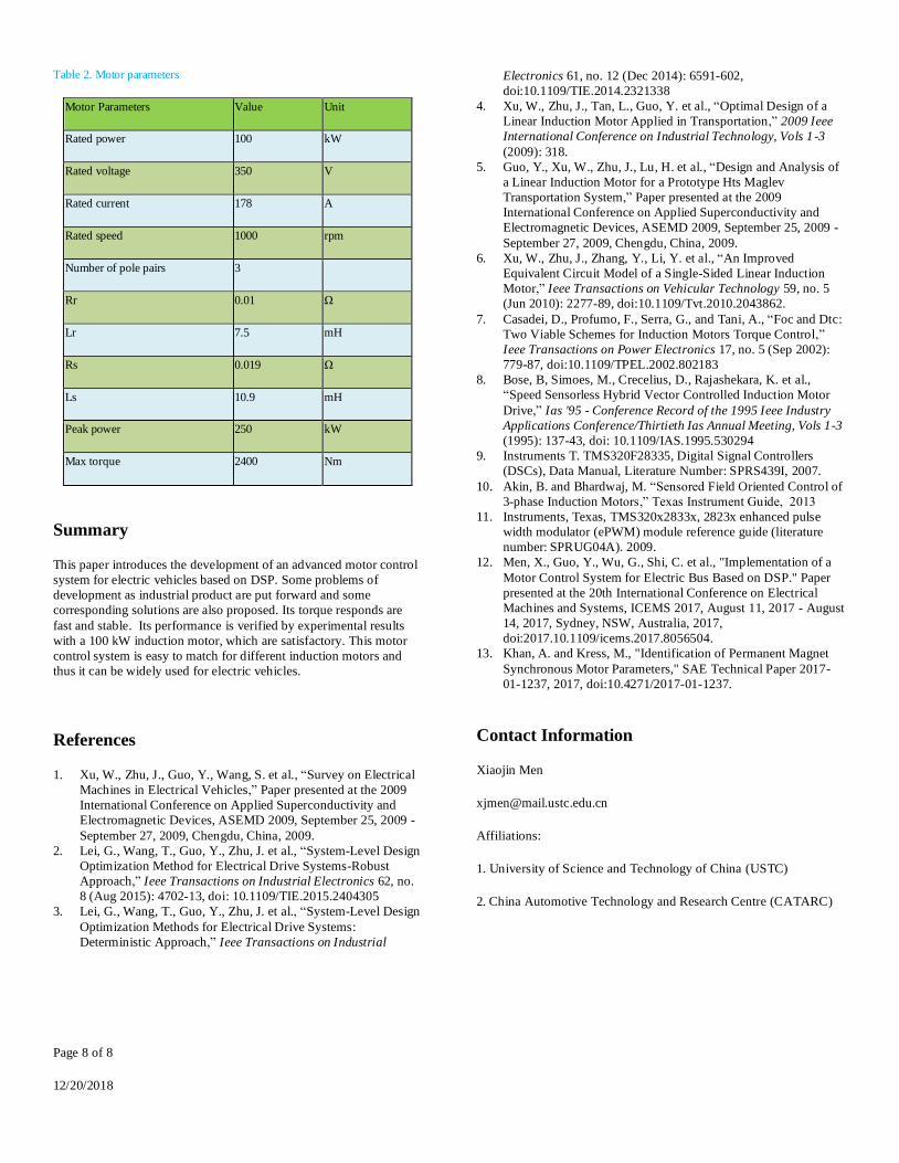
etc. The parameters [13] of target motor is listed in Table 2.

Page 7 of 8
12/20/2018
The experiment is carried out on a towing electric motor test bench.
When the experiments are conducted for testing speed performance,
the opposite motor will offer a fix torque. When the experiments are
conducted for torque performance, the opposite motor will offer a fix
speed. By doing these, the transient performance and steady state
performance can be achieved.
When the electric vehicle driver gives an acceleration signal, it will
be finally transferred to an 𝐼𝑞 value by the motor control system and
then carried out to obtain a demanded torque and the speed of vehicle
increases as a consequence. For experiment at lab, the motor control
system can be connected with PC and the instruction is given by
software in PC. The load motor can be set to run at a fix speed and
then different 𝐼𝑞 is set to acquire the torque performance of target
motor. The responses of torque regarding to different input values of
𝐼𝑞 , is shown in Figure 13 and the torque ripples around rated value
(1000 Nm) is shown in Figure 14. The voltage and phase current is
shown in figure 15 and figure 16. Voltage doesn’t change much
during change of Iq. Phase current increases with the increase of Iq
and these three phase current is balanced all the time as Figure 16
shows. In Figure 13, Iq is increased step by step, while the speed is
fixed by the opposite motor as a load. The transient response is
satisfactory and its torque is very stable with a ripple of under ±3%,
which is normally considered as a good performance for electric bus.
Figure 12. Experiment setup.
Figure 13. Torque responses versus changing Iq
Figure 14. Ripples at rated torque.
Figure 15. Voltage responses versus changing Iq
Figure 16. Phase current responses versus changing Iq
0 1 2 3 4 5 6 7 8
x 104
-500
0
500
1000
1500
2000
time(ms)
torq
ue(N
m),
speed(r
pm
)
Torque at rated speed
torque
speed
2.75 2.8 2.85 2.9 2.95 3 3.05 3.1 3.15 3.2
x 104
880
900
920
940
960
980
1000
1020
time(ms)
torq
ue(N
m),
speed(r
pm
)
Torque at rated speed
torque
speed
0 1 2 3 4 5 6 7 8
x 104
335
340
345
350
355
360
365
370
375
380
385
time(ms)
Voltage(V
)
Voltage
U1
U2
U3
0 1 2 3 4 5 6 7 8
x 104
50
100
150
200
250
300
350
400
time(ms)
Curr
ent(
A)
Current
I1
I2
I3
Page 8 of 8
12/20/2018
Table 2. Motor parameters
Motor Parameters Value Unit
Rated power 100 kW
Rated voltage 350 V
Rated current 178 A
Rated speed 1000 rpm
Number of pole pairs 3
Rr 0.01 Ω
Lr 7.5 mH
Rs 0.019 Ω
Ls 10.9 mH
Peak power 250 kW
Max torque 2400 Nm
Summary
This paper introduces the development of an advanced motor control
system for electric vehicles based on DSP. Some problems of
development as industrial product are put forward and some
corresponding solutions are also proposed. Its torque responds are
fast and stable. Its performance is verified by experimental results
with a 100 kW induction motor, which are satisfactory. This motor
control system is easy to match for different induction motors and
thus it can be widely used for electric vehicles.
References
1. Xu, W., Zhu, J., Guo, Y., Wang, S. et al., “Survey on Electrical
Machines in Electrical Vehicles,” Paper presented at the 2009
International Conference on Applied Superconductivity and
Electromagnetic Devices, ASEMD 2009, September 25, 2009 -
September 27, 2009, Chengdu, China, 2009.
2. Lei, G., Wang, T., Guo, Y., Zhu, J. et al., “System-Level Design
Optimization Method for Electrical Drive Systems-Robust
Approach,” Ieee Transactions on Industrial Electronics 62, no.
8 (Aug 2015): 4702-13, doi: 10.1109/TIE.2015.2404305
3. Lei, G., Wang, T., Guo, Y., Zhu, J. et al., “System-Level Design
Optimization Methods for Electrical Drive Systems:
Deterministic Approach,” Ieee Transactions on Industrial
Electronics 61, no. 12 (Dec 2014): 6591-602,
doi:10.1109/TIE.2014.2321338
4. Xu, W., Zhu, J., Tan, L., Guo, Y. et al., “Optimal Design of a
Linear Induction Motor Applied in Transportation,” 2009 Ieee
International Conference on Industrial Technology, Vols 1-3
(2009): 318.
5. Guo, Y., Xu, W., Zhu, J., Lu, H. et al., “Design and Analysis of
a Linear Induction Motor for a Prototype Hts Maglev
Transportation System,” Paper presented at the 2009
International Conference on Applied Superconductivity and
Electromagnetic Devices, ASEMD 2009, September 25, 2009 -
September 27, 2009, Chengdu, China, 2009.
6. Xu, W., Zhu, J., Zhang, Y., Li, Y. et al., “An Improved
Equivalent Circuit Model of a Single-Sided Linear Induction
Motor,” Ieee Transactions on Vehicular Technology 59, no. 5
(Jun 2010): 2277-89, doi:10.1109/Tvt.2010.2043862.
7. Casadei, D., Profumo, F., Serra, G., and Tani, A., “Foc and Dtc:
Two Viable Schemes for Induction Motors Torque Control,”
Ieee Transactions on Power Electronics 17, no. 5 (Sep 2002):
779-87, doi:10.1109/TPEL.2002.802183
8. Bose, B, Simoes, M., Crecelius, D., Rajashekara, K. et al.,
“Speed Sensorless Hybrid Vector Controlled Induction Motor
Drive,” Ias '95 - Conference Record of the 1995 Ieee Industry
Applications Conference/Thirtieth Ias Annual Meeting, Vols 1-3
(1995): 137-43, doi: 10.1109/IAS.1995.530294
9. Instruments T. TMS320F28335, Digital Signal Controllers
(DSCs), Data Manual, Literature Number: SPRS439I, 2007.
10. Akin, B. and Bhardwaj, M. “Sensored Field Oriented Control of
3-phase Induction Motors,” Texas Instrument Guide, 2013
11. Instruments, Texas, TMS320x2833x, 2823x enhanced pulse
width modulator (ePWM) module reference guide (literature
number: SPRUG04A). 2009.
12. Men, X., Guo, Y., Wu, G., Shi, C. et al., "Implementation of a
Motor Control System for Electric Bus Based on DSP." Paper
presented at the 20th International Conference on Electrical
Machines and Systems, ICEMS 2017, August 11, 2017 - August
14, 2017, Sydney, NSW, Australia, 2017,
doi:2017.10.1109/icems.2017.8056504.
13. Khan, A. and Kress, M., "Identification of Permanent Magnet
Synchronous Motor Parameters," SAE Technical Paper 2017-
01-1237, 2017, doi:10.4271/2017-01-1237.
Contact Information
Xiaojin Men
Affiliations:
1. University of Science and Technology of China (USTC)
2. China Automotive Technology and Research Centre (CATARC)