Module 16 - West Virginia Universityddean/CE210/AutoCAD Civil 3D 2009... · Module 16 - Roadway ......
65
NOTES Module 16 Roadway Assemblies and Corridors In this module, you learn how to work with roadway assemblies and corridors in AutoCAD Civil 3D. Objectives After completing this module, you will be able to: Navigate the Subassembly Catalog. Add subassemblies to a tool palette and modify subassembly properties. Create an assembly and modify the assembly properties. Create a corridor. Modify the corridor properties. Create a corridor surface. Prepare a 3D model of the finished road design.
Transcript of Module 16 - West Virginia Universityddean/CE210/AutoCAD Civil 3D 2009... · Module 16 - Roadway ......

NOTES
Module 16
Roadway Assemblies and Corridors
In this module, you learn how to work with roadway assemblies and corridors
in AutoCAD Civil 3D.
Objectives
After completing this module, you will be able to:
Navigate the Subassembly Catalog.
Add subassemblies to a tool palette and modify subassembly properties.
Create an assembly and modify the assembly properties.
Create a corridor.
Modify the corridor properties.
Create a corridor surface.
Prepare a 3D model of the finished road design.

AutoCAD Civil 3D 2009 Education Curriculum NOTES
16-2
Notes to Instructor
Data for this module resides in the \AutoCAD Civil 3D 2009 Education
Curriculum\Module 16 - Roadway Assemblies and Corridors\ folder.
Exercises
The following exercises are provided in step-by-step format. Open the
AutoCAD Civil 3D program prior to beginning the lesson by double-clicking
the Civil 3D icon on the desktop.
Those working in the imperial system should use the drawing files beginning
with the letter I, while those working in the metric system should use the
drawing files beginning with the letter M. A drawing is provided for each
exercise in the lesson.
You must open the drawing provided with each exercise.
The exercises in this module are as follows:
1. Navigate the Subassembly Catalog
2. Add Subassemblies to Tool Palette and Modify Subassembly Properties
3. Create an Assembly and Modify Assembly Properties
4. Create a Corridor
5. Modify the Corridor Properties
6. Create a Corridor Surface
7. Prepare 3D Model of Finished Road Design

Module 16 - Roadway Assemblies and Corridors NOTES
16-3
Roadway Assemblies and Corridors
This module introduces AutoCAD Civil 3D assembly and corridor
functionality that can be applied to road and highway engineering projects.
A road or highway transportation design is based on a typical section, which
governs the overall configuration of the cross section. The typical section
dictates the following:
Elements represented in the cross section: lanes, shoulders, curbs,
sidewalks, barriers, guardrails, slopes, and so on.
Geometric configuration of the elements: widths, grades, slopes, depths,
and materials.
AutoCAD Civil 3D uses assembly objects to represent a typical cross
section. An assembly that incorporates lanes, shoulders, guardrails, and
match (catch) slope subassembly objects is as shown.
Assemblies are created from subassembly objects. Subassemblies are used
to represent the cross section elements. The Civil 3D assembly object
shown is used to create a corridor model and consists of lane, shoulder,
guardrail, and match slope subassemblies.
AutoCAD Civil 3D comes with many stock subassemblies that can be used
for a number of different typical section elements.
Subassemblies are organized in categories in the Subassembly Catalog.

AutoCAD Civil 3D 2009 Education Curriculum NOTES
16-4
You organize the subassemblies that you regularly use on AutoCAD tool
palettes. You can copy subassemblies from the Subassembly Catalog to
your tool palettes.
Subassemblies use input parameters that enable you to modify the properties
of the subassemblies prior to use. Using input parameters, you can control
the geometric properties of the subassemblies and specify widths, slopes,
and depths. You modify the default input parameters of the subassemblies
on the tool palette.
Module 16 - Roadway Assemblies and Corridors NOTES
16-5
To build a typical section, you first insert an assembly object to the drawing
and assign a name.
Once the assembly object has been created, you then attach the
subassemblies from the tool palette. The following illustration shows an
assembly with two subassemblies to represent the right and left lanes.
Subassembly objects contain points, links, and shapes. Points represent the
singular locations and are used to create corridor feature lines. Points can
also be used for annotating design cross sections and creating construction
staking data. Links connect the points and are used to create corridor
surfaces and annotate grades on design cross sections. Shapes connect the
links and are used to calculate pavement structure volumes and annotate
pavement structure end areas.
After the assembly has been created, you then create the corridor object. A
corridor is used to represent the final road design and is constructed using an

AutoCAD Civil 3D 2009 Education Curriculum NOTES
16-6
alignment, a profile, and an assembly. You can also use other alignments
and profiles to control the construction of a corridor. For example, an
alignment representing a proposed edge of pavement (EOP) can be used to
control the lane width.
Once the corridor has been created, you can view the corridor in 3D using
the AutoCAD Object Viewer.
You can also view and edit the corridor sections for each station along the
corridor.
For each station, you can modify the subassembly input parameters. You
can also change the values for a range of stations.

Module 16 - Roadway Assemblies and Corridors NOTES
16-7
After you have created the corridor, you can modify the corridor properties
to perform the following tasks:
Add, remove, and change corridor regions. Regions are longitudinal
segments along a corridor, delineated with a start and end station. A
different assembly can be assigned to each region.
Change the assembly insertion frequency, or the interval along the
alignment at which an assembly is inserted to create the corridor.
Define target mapping for specific subassemblies. For example, the
match slope (daylighting) subassemblies need to know which surface to
project the slopes to. This is called target mapping.

AutoCAD Civil 3D 2009 Education Curriculum NOTES
16-8
You can also create corridor surfaces when you modify the corridor
properties.
Corridor surfaces can be created from links or feature lines. Corridor
surfaces are most often created from the datum and top links. All
subassemblies have datum and top links.
The datum links are located on the bottom of the assembly and are used to
create a corridor datum surface. A corridor datum surface is used for
calculating earthwork cut and fill volumes.
The top links are located on the top of the assembly and are used to create a
corridor top surface. A corridor top surface can be used to:
Create 3D models of proposed roads.
Label design spot elevations and grades.
Calculate manhole rim and pipe invert elevations for pipe networks.
Civil 3D surface styles are used to control the display of the corridor
surfaces. Corridor surface boundaries are defined from the corridor feature
lines, which are the longitudinal lines that run along the length of the

Module 16 - Roadway Assemblies and Corridors NOTES
16-9
corridor. Examples of corridor feature lines include edge of traveled way
(ETW), edge of paved shoulder (EPS), and daylight.
Note: ETW and EPS are Civil 3D codes for edge of pavement (EOP) and
edge of shoulder (EOS).
Daylight feature lines are most often used as boundaries for corridor datum
and top surfaces.
You can create 3D models of corridors by combining surfaces together. For
example, you combine the existing ground surface and the corridor top
surface to create a surface that consists of both existing and proposed surface
data. You use the surface Paste command to combine data from two
surfaces.
You can also assign render materials to the corridor to quickly create
photorealistic renderings of your model.

AutoCAD Civil 3D 2009 Education Curriculum NOTES
16-10

Module 16 - Roadway Assemblies and Corridors NOTES
16-11
Key Terms
Assembly The Civil 3D object used to represent the typical cross section. The
assembly is created by adding subassemblies.
Assembly
Insertion
Frequency
The frequency along an alignment at which assemblies are inserted to create
the corridor.
Codes Subassemblies consist of unique codes. Codes are used to identify the
names of the points, links, and shapes that make up a subassembly.
Code Set Style A library of codes and the marker styles, link styles, shape style, and render
materials assigned to codes.
Corridor The Civil 3D object used to represent the road design.
Corridor
Region
A segment along a corridor defined with a start station and an end station.
You can use multiple corridor regions. For each corridor region you can
assign a different assembly, assembly insertion frequency, and target
mapping parameters.
Corridor
Surface
A Civil 3D surface that is created from a corridor model to represent a
specific layer of the cross section. Common corridor surfaces include top
and datum surfaces.
Daylighting The projection of a match slope to a surface. AutoCAD Civil 3D uses a
number of subassemblies that can be used for daylighting.
Feature Lines Used to represent the longitudinal lines along a corridor. Feature lines are
created by connecting the subassembly points found in the assembly used to
create the corridor.
Feature Line
Style
Used to control the display of corridor feature lines.
Paste The surface editing action of combining data from two surfaces.
Subassembly
Catalog
A library of stock subassemblies that come with AutoCAD Civil 3D.

AutoCAD Civil 3D 2009 Education Curriculum NOTES
16-12
Subassembly
Link
Links connect the subassembly points. Subassembly links are used to create
corridor surfaces and can also be used to annotate slopes and grades on
design cross sections. You can also assign render materials to subassembly
links to quickly create photorealistic renderings of the corridor design.
Subassembly
Point
The singular locations on a subassembly. Examples of subassembly points
include edge of traveled way (ETW) and edge of paved shoulder (EPS).
These are connected to create corridor feature lines when the corridor is
created. They can also be used to create construction staking points and to
label offsets and elevations on design cross sections.
Subassembly
Shape
Closed shapes used to represent the structure materials in the subassemblies.
Materials include pavement, granular, and concrete. Subassembly shapes
are used to calculate material volumes and can be used to annotate end areas
on design cross sections.
Subassembly
Input
Parameters
All subassemblies use editable input parameters that enable you to change
the geometric properties of the subassembly including width, slope, grade,
and depth.
Target
Mapping
Subassemblies use target mapping to control how they function.
Subassemblies used for daylighting use a required target to indicate which
surface to project the match slope to. Subassemblies for lanes use an
optional target alignment to control the width.
Typical
Section
The typical section represents the typical cross section configuration for a
road or highway design. The typical section is part of the design criteria and
indicates the cross section elements (lanes, shoulders, curbs, and so on) and
their geometric configuration.

Module 16 - Roadway Assemblies and Corridors NOTES
16-13
EXERCISE 1: NAVIGATE THE SUBASSEMBLY CATALOG
In this exercise, you learn about AutoCAD Civil 3D subassemblies and how to
navigate the Subassembly Catalog.
A typical section for a road or highway design is used to indicate the typical
cross section configuration details. These details include the elements that are
included in the cross section (lanes, shoulders, curbs, barriers, and so on) and
their design parameters. Examples of the design parameters include width,
slope, grade, and depth.
AutoCAD Civil 3D uses subassemblies to represent the different elements of a
typical cross section. Subassemblies are available for a number of cross
section elements including lanes, shoulders, curbs, barriers, guardrails,
sidewalks, and match slopes. Subassemblies are organized in categories in the
Subassembly Catalog.
All subassemblies have an associated Help file that offers instruction on how
to use the subassembly.
Civil 3D assemblies represent the typical section and are constructed from
subassemblies.
For this exercise, open …\Module 16 – Roadway Assemblies and
Corridors\I_RoadwayAssembliesandCorridors-EX1.dwg
(M_RoadwayAssembliesandCorridors-EX1.dwg).
1. Click Corridors menu > Subassembly Catalog.
Civil 3D displays the Autodesk Content Browser.

AutoCAD Civil 3D 2009 Education Curriculum NOTES
16-14
2. Click Corridor Modeling Catalogs Imperial (Corridor Modeling Catalogs
Metric).
3. Click C3D Imperial Transportation Design Subassembly Catalog (Civil 3D
Metric Transportation Design Subassembly Catalog).
Notice that the Civil 3D subassemblies are organized into other catalogs
for lanes, medians, shoulders, and so on.
4. Click Lanes.
Civil 3D displays a number of subassemblies for different lane

Module 16 - Roadway Assemblies and Corridors NOTES
16-15
configurations.
5. Right-click LaneOutsideSuper and click Help.
6. Review the contents of the Help document for the LaneOutsideSuper
subassembly.
Every subassembly has its own Help document.
This Help document describes how the LaneOutsideSuper subassembly is
used. The Help documentation for all subassemblies consists of the following
categories:
Attachment
Subassemblies are combined to create the assembly or typical section for the
road design. The attachment describes the attachment point for the
subassemblies.
You can attach a subassembly directly to the assembly object or to another
subassembly.
Input Parameters
Every subassembly has a number of variable input parameters. You can
configure each subassembly to satisfy the requirements of the typical cross
section.
Target Parameters
Some subassemblies use Target parameters to override the input parameters.
For example, the Width input parameter for the LaneOutsideSuper
subassembly can be overridden by assigning an optional Alignment Target
parameter.
This means that you can vary the lane width by linking the outer edge of the
subassembly to an edge of pavement alignment. With the LaneOutsideSuper
subassembly, you can also vary the cross slope with a Profile Target parameter

AutoCAD Civil 3D 2009 Education Curriculum NOTES
16-16
and control the elevation of the outer edge of the subassembly.
Output Parameters
Some subassemblies have output parameters, which can be used as input
parameters to other subassemblies.
Behavior
The Behavior section describes how the subassembly works.
Point, Link, and Shape Codes
Every subassembly consists of points, links, and shapes with unique identities.
The coding diagram and code list are used to identify and describe the point,
link, and shape codes on the subassembly.
A corridor model is created by connecting similar points along the length of
the alignment. Points can also be used to annotate offsets and elevations on
design sections. Links can be used to create corridor surfaces and are also
used to annotate slopes and grades on design sections. Shapes are used to
calculate pavement structure (granular, asphalt, concrete, and so on) quantities,
and can be used to annotate end areas.
7. Peruse the Subassembly Catalog and review the Help documents for some
of the other subassemblies.
8. Close the Help document for the LaneOutsideSuper subassembly.
9. Close the Subassembly Catalog.
10. Close the drawing and do not save the changes.
Module 16 - Roadway Assemblies and Corridors NOTES
16-17
EXERCISE 2: ADD SUBASSEMBLIES TO TOOL PALETTE AND MODIFY SUBASSEMBLY
PROPERTIES
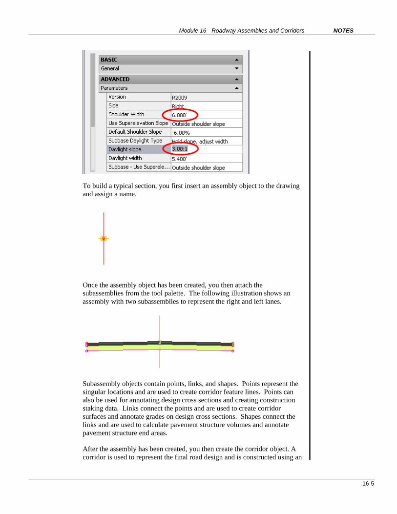
You can copy subassemblies from the Subassembly Catalog to tool palettes.
You organize the tool palettes so they contain the subassemblies that you
regularly use.
Tool palettes are organized in palette groups. You can create your own and
select subassemblies from a number of different palette groups.
Once subassemblies have been copied to a tool palette, you can modify the
default input parameters for the subassemblies.
You can also rename the subassemblies on the tool palette.

AutoCAD Civil 3D 2009 Education Curriculum NOTES
16-18
In this exercise you:
Create a new tool palette.
Copy the subassemblies from the Subassembly Catalog to
the tool palette.
Modify the subassembly parameters on the tool palette.
Rename the subassemblies.
For this exercise, open …\Module 16 – Roadway Assemblies and
Corridors\I_RoadwayAssembliesandCorridors-EX2.dwg
(M_RoadwayAssembliesandCorridors-EX2.dwg).
Create a New Tool Palette
Begin by opening and configuring the Tool Palettes window.
1. Close the Toolspace window and all other workspace windows.
2. Press CTRL+3 on the keyboard to open the Tool Palettes window.
3. Position the Tool Palettes window on the right side of the screen, undocked.

Module 16 - Roadway Assemblies and Corridors NOTES
16-19
4. Right-click the Tool Palettes window. Click Customize Palettes.
5. On the right side of the Customize dialog box, scroll to the top of the list.
6. Right-click Civil 3D - Imperial (Civil 3D - Metric). Click Set Current.
You now create a new Tool Palette on the Tool Palettes window.
7. Click Close.
8. Right-click the Tool Palettes window. Click New Palette.
9. For the Tool Palette Name, enter Module 16 Roads. Press ENTER.

AutoCAD Civil 3D 2009 Education Curriculum NOTES
16-20
Now open the Civil 3D Subassembly Catalog.
10. Click Corridors menu > Subassembly Catalog.
11. Adjust the size of the Autodesk Content Browser window and position it on
the screen so you can see both the Content Browser and the Tool Palettes
window.
Copy the Subassemblies from the Subassembly Catalog to the Tool Palette
You now copy the required subassemblies from the Subassembly Catalog to the
Tool Palettes window.
1. Click in the Autodesk Content Browser window.
2. Click Corridor Modeling Catalogs Imperial (Corridor Modeling Catalogs
Metric).

Module 16 - Roadway Assemblies and Corridors NOTES
16-21
3. Click C3D Imperial Transportation Design Subassembly Catalog (Civil 3D
Metric Transportation Design Subassembly Catalog).
4. Click Lanes.
5. For LaneOutsideSuper, hold the mouse over the blue i-drop icon.
6. Click and drag the LaneOutsideSuper subassembly to the Tool Palettes
window created earlier.
The LaneOutsideSuper subassembly is copied to the Tool Palettes window.
7. Click in the Autodesk Content Browser window.
8. Click Back.
9. Click Shoulders.
10. Using the same procedure, copy the ShoulderExtendSubbase subassembly to
the Tool Palettes window.

AutoCAD Civil 3D 2009 Education Curriculum NOTES
16-22
11. Click in the Autodesk Content Browser window.
12. Click Back twice.
13. Click the C3D Imperial Getting Started Subassembly Catalog (C3D Metric
Getting Started Subassembly Catalog).
14. Using the same procedure, copy the BasicGuardrail, Basic Barrier, and
BasicSideSlopeCutDitch subassemblies to the Tool Palettes window.
The subassemblies you need are now on the tool palette. The next step is to
modify the subassembly parameters.
Modify Subassembly Properties
In these next few steps, you modify the default input parameters for the
LaneOutsideSuper, ShoulderExtendSubbase, and BasicSideSlopeCutDitch
subassemblies.
1. On the Tool Palettes window, right-click LaneOutsideSuper. Click
Properties.
2. In the Tool Properties dialog box, click to close BASIC.
Civil 3D displays the input parameters for the subassembly in the
ADVANCED area of the Tool Properties window.
3. For Width, enter 14 (3.75 m).

Module 16 - Roadway Assemblies and Corridors NOTES
16-23
4. Click OK.
5. On the Tool Palettes window, right-click ShoulderExtendSubbase. Click
Properties.
6. In the Tool Properties dialog box, click to close BASIC.
7. For Shoulder Width, enter 6 (2 m).
8. For Daylight Slope, enter 3.
9. Click OK.
10. On the Tool Palettes window, right-click BasicSideSlopeCutDitch. Click
Properties.
11. In the Tool Properties dialog box, click to close BASIC.
AutoCAD Civil 3D 2009 Education Curriculum NOTES
16-24
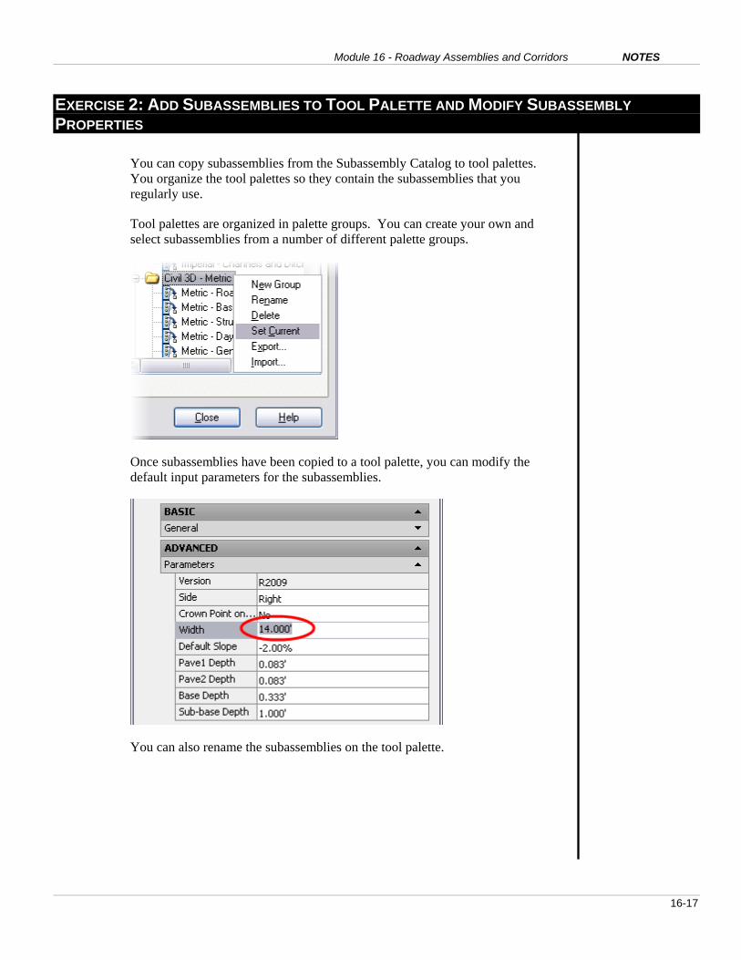
12. For Fill Slope, enter 2. Press ENTER.
13. Click OK.
Rename the Subassemblies
Now rename the subassemblies on the tool palette.
1. On the Tool Palettes window, right-click LaneOutsideSuper and click
Rename.
2. Change the name to Lane.
3. Repeat the process and rename the other subassemblies as follows:
Old Name New Name
ShoulderExtendSubbase Shoulder
BasicGuardrail Guardrail
BasicSideSlopeCutDitch Match Slope
BasicBarrier Barrier

Module 16 - Roadway Assemblies and Corridors NOTES
16-25
4. Close the Autodesk Content Browser window.
5. Close the drawing and do not save the changes.

AutoCAD Civil 3D 2009 Education Curriculum NOTES
16-26
EXERCISE 3 – CREATE AND ASSEMBLY AND MODIFY ASSEMBLY PROPERTIES
Assemblies are Civil 3D objects used to create the corridor model and represent
the typical cross section for a road or highway. You create an assembly and then
add the subassemblies to the assembly.
You use the Object Properties and Tool Palettes windows when you create an
assembly. A workspace is a customizable interface created to suit the current
task. A workspace can be created to represent an assembly construction
interface.
The assembly you create in this exercise consists of lanes, shoulders, guardrails,
and match slopes. When you create the assembly, the subassemblies are
organized into assembly groups. A new assembly group is created when you
pick the assembly to insert a subassembly.

Module 16 - Roadway Assemblies and Corridors NOTES
16-27
After you create the assembly, you rename the assembly groups to indicate either
the left or right side.
For this exercise, open …\Module 16 – Roadway Assemblies and Corridors\
RoadwayAssembliesandCorridors-EX3.dwg
(M_RoadwayAssembliesandCorridors-EX3.dwg).
Create Workspace
Begin by creating and configuring an AutoCAD workspace for assembly
creation. You create a new workspace for assembly creation that uses the Object
Properties and Tool Palettes windows.
1. On the Workspaces toolbar, click Workspace Settings.
2. Select Automatically Save Workspace Changes.

AutoCAD Civil 3D 2009 Education Curriculum NOTES
16-28
3. Click OK.
4. Ensure the current workspace is set to Civil 3D Complete.
5. Click the drop-down arrow on the Workspaces toolbar. Select Save Current
As.
6. In the Save Workspace dialog box, for Name, enter Assembly Creation.
7. Click Save.
When you create the assembly, you use the Tool Palettes window and the
Object Properties window. In the next few steps, you position these
windows.
8. Close all dialog boxes and workspaces so the graphics area is clear.
9. Press CTRL + 1 on the keyboard to open the Object Properties window.
10. Position the Object Properties window on the left side of the screen,
undocked.
11. Press CTRL + 3 on the keyboard to open the Tool Palettes window.
12. Position the Tool Palettes window on the right side of the screen, undocked.

Module 16 - Roadway Assemblies and Corridors NOTES
16-29
You are now ready to create the assembly.
Create the Assembly
1. Click Corridors menu > Create Assembly.
2. In the Create Assembly dialog box, for Name, enter 2 Lane Rural.
3. Click OK.
4. Select a location anywhere in the drawing area to create the assembly.
Civil 3D creates the assembly object in the drawing. The subassemblies are
attached to the assembly object.
AutoCAD Civil 3D 2009 Education Curriculum NOTES
16-30
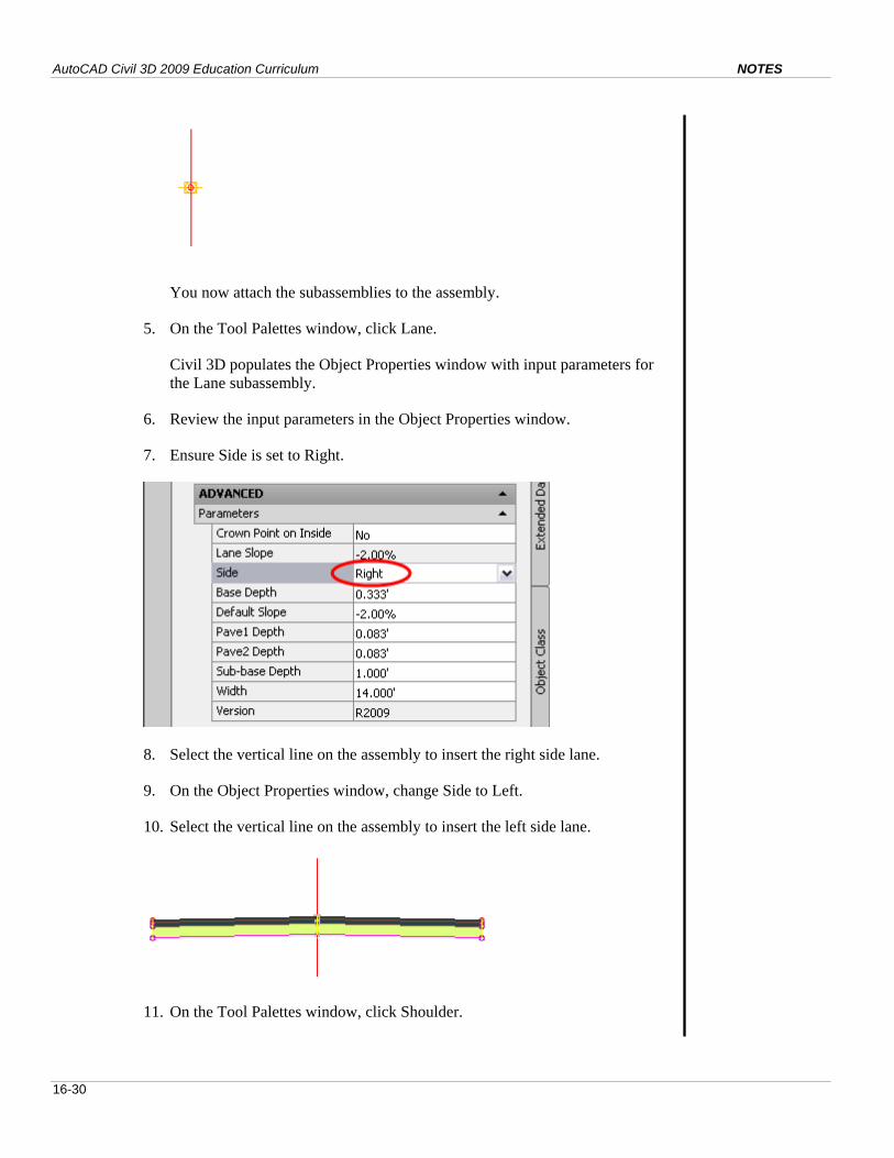
You now attach the subassemblies to the assembly.
5. On the Tool Palettes window, click Lane.
Civil 3D populates the Object Properties window with input parameters for
the Lane subassembly.
6. Review the input parameters in the Object Properties window.
7. Ensure Side is set to Right.
8. Select the vertical line on the assembly to insert the right side lane.
9. On the Object Properties window, change Side to Left.
10. Select the vertical line on the assembly to insert the left side lane.
11. On the Tool Palettes window, click Shoulder.

Module 16 - Roadway Assemblies and Corridors NOTES
16-31
12. Review the input parameters in the Object Properties window.
13. Ensure Side is set to Right.
14. Zoom in and click the top outer right lane marker point to attach the right
shoulder subassembly.
15. On the Object Properties window, change Side to Left.
16. Zoom to and click the outer left lane marker point to attach the left shoulder
subassembly.
The assembly now contains the shoulders.
Note: You can use the Erase command to erase a subassembly if it was
inserted on the wrong side.
Now add the guardrails.
Note: Metric users, use the Barrier subassembly and not the Guardrail
subassembly.
17. On the Tool Palettes window, click Guardrail (Metric: Barrier).
18. On the Object Properties window, ensure Side is set to Right.
19. Select the top marker on the outside edge of the shoulder pavement

AutoCAD Civil 3D 2009 Education Curriculum NOTES
16-32
structure.
20. Repeat the step and add the Guardrail subassembly (Metric: Barrier
subassembly) to the left side.
The guardrails (Metric: barriers) are now on both sides.
Now add the match slopes.
21. On the Tool Palettes window, click Match Slope.
22. On Object Properties, ensure the side is set to Right.
23. Zoom in and select the subassembly marker on right side of the right
shoulder.

Module 16 - Roadway Assemblies and Corridors NOTES
16-33
24. Repeat the step and add the Match Slope subassembly to the left side.
25. Press the ESC key when finished.
The construction of the 2 Lane Rural assembly is complete.
Modify Assembly Properties
You modify the properties of the assembly to rename assembly groups and the
subassemblies.
First, restore the Civil 3D Complete Workspace. This redisplays the Toolspace
window.
1. On the Workspaces toolbar, click the drop-down list and change the
workspace to Civil 3D Complete.
Now modify the assembly properties to rename the subassemblies for ease
of use.
2. In Toolspace, click the Prospector tab.
3. Expand the Assemblies tree.
4. Right-click 2 Lane Rural. Click Properties.
5. In the Assembly Properties dialog box, click the Construction tab.

AutoCAD Civil 3D 2009 Education Curriculum NOTES
16-34
Subassemblies are organized into groups. A new group is created when you
select the assembly object to add the subassemblies.
6. Rename the subassembly groups to Right Side and Left Side as shown.
Tip: Right-click the item and click Rename, or click the Item and press the
F2 key on the keyboard.
Note: Metric users, rename the barriers to Barrier Left and Barrier Right.
7. Click OK.
8. Close the drawing and do not save the changes.

Module 16 - Roadway Assemblies and Corridors NOTES
16-35
EXERCISE 4: CREATE A CORRIDOR AND VIEW/EDIT CORRIDOR SECTIONS
The corridor represents the final design of the road or highway. The assembly is
processed along the horizontal and vertical alignments at the assembly insertion
frequency.
When you create a corridor, you select an alignment, profile, and assembly.
The daylighting subassemblies used in an assembly need to know which surface to
project their slopes to. This is called target mapping. You assign surface targets to
the match slope subassemblies when you create the corridor.
After you create the corridor, you view the corridor in the Object Viewer.

AutoCAD Civil 3D 2009 Education Curriculum NOTES
16-36
.
With the View/Edit Corridor Sections command, you can view and modify the cross-
section data at each station location.
For this exercise, open …\Module 16 – Roadway Assemblies and Corridors\
I_RoadwayAssembliesandCorridors-EX4.dwg
(M_RoadwayAssembliesandCorridors-EX4.dwg).
1. Click Corridor menu > Create Simple Corridor.
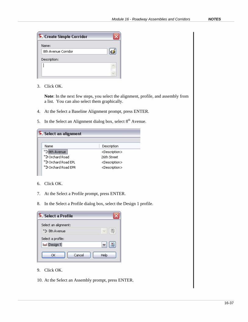
2. In the Create Simple Corridor dialog box, for Name, enter 8th Avenue Corridor.
Module 16 - Roadway Assemblies and Corridors NOTES
16-37
3. Click OK.
Note: In the next few steps, you select the alignment, profile, and assembly from
a list. You can also select them graphically.
4. At the Select a Baseline Alignment prompt, press ENTER.
5. In the Select an Alignment dialog box, select 8th Avenue.
6. Click OK.
7. At the Select a Profile prompt, press ENTER.
8. In the Select a Profile dialog box, select the Design 1 profile.
9. Click OK.
10. At the Select an Assembly prompt, press ENTER.

AutoCAD Civil 3D 2009 Education Curriculum NOTES
16-38
11. In the Select an Assembly dialog box, select 2 Lane Rural Assembly. Click OK.
You now assign targets to the subassemblies in the assembly. The Match Slope
Left and Right subassemblies need a target surface assigned.
12. In the Target Mapping dialog box, click in the Surfaces row, Object Name
column.
13. Select Existing Ground.
14. Click OK.
15. Click OK.
Civil 3D creates the corridor object.

Module 16 - Roadway Assemblies and Corridors NOTES
16-39
You now analyze the corridor using the Object Viewer.
16. In the drawing area, select the corridor.
17. Right-click and click Object Viewer.
Civil 3D displays the corridor in the Object Viewer window. You can use the
Object Viewer controls to view the corridor.
18. Change the view to SW Isometric.
19. Experiment with the other settings in the Object Viewer to view the corridor in
3D.

AutoCAD Civil 3D 2009 Education Curriculum NOTES
16-40
Note: Do not click Set View. This button sets the drawing to the current view.
If necessary, you can restore the plan view with View menu > 3D Views > Top.
20. Close the Object Viewer window when you are done.
View/Edit Corridor Sections
You now view and edit the corridor sections.
1. Click Corridors menu > View / Edit Corridor Section.
2. At the Select a Corridor prompt, press ENTER.
3. In the Select a corridor dialog box, select 8th Avenue corridor. Click OK.
Civil 3D displays the View/Edit Corridor Sections Tools toolbar and displays the
first cross section.
4. On the toolbar, click and to show the other sections.
5. Change the station to 21+00 (Metric: 10+350).
Notice the superelevation on the cross section.

Module 16 - Roadway Assemblies and Corridors NOTES
16-41
6. Click to expand the toolbar.
7. Close the trees as shown.
8. Expand the Match Slope Right tree.
9. For Cut Slope, in the Value Column, enter 4. Press ENTER.
The selected check box and the word True in the Override column indicates that

AutoCAD Civil 3D 2009 Education Curriculum NOTES
16-42
an override has been placed on the lane width. Note that the lane width updates
in the drawing area.
Now apply the override to a station range.
10. On the Toolbar, click Apply to a Station Range.
11. In the Apply to a Range of Stations dialog box, for End station, enter 2200
(Metric: 10500).
12. Click OK.
13. Close the View/Edit Corridor Section Tools toolbar.
14. Review the updated corridor model in the drawing area.
15. Close the drawing and do not save the changes.

Module 16 - Roadway Assemblies and Corridors NOTES
16-43
EXERCISE 5: MODIFY THE CORRIDOR PROPERTIES
In this section, you change the design parameters by modifying the Corridor
properties.
Corridor regions are linear segments along a corridor to which an assembly is
applied. Every corridor region has a start station and end station. A corridor can
consist of several corridor regions.
When you modify the Corridor properties, you can specify the start and end station
for a corridor region.
The assembly insertion frequency is the interval at which the assembly is inserted to
create the corridor. You change the assembly insertion frequency when you modify
the Corridor properties.
The assembly insertion frequency can be modified for each corridor region.
Feature lines are the longitudinal lines along the corridor and are automatically
created by connecting the subassembly points. A feature line style is used to control
the display of the feature lines. When you modify the corridor properties, you can
turn feature lines on and off and assign feature line styles.

AutoCAD Civil 3D 2009 Education Curriculum NOTES
16-44
For this exercise, open …\Module 16 – Roadway Assemblies and Corridors\
I_RoadwayAssembliesandCorridors-EX5.dwg
(M_RoadwayAssembliesandCorridors-EX5.dwg).
1. Click the Prospector tab in the Toolspace window.
2. Expand the Corridors tree.
3. Right-click 8th Avenue Corridor. Click Properties.
4. In the Corridor Properties dialog box, click the Parameters tab.
The corridor uses the 2 Lane Rural Assembly north of the intersection of 8th
Avenue and Orchard Road. You now specify the station for the beginning of
the corridor.
5. Click the Select Station symbol in the Start Station column.
6. Using the Endpoint object snap, select the northwest corner of Parcel 1.

Module 16 - Roadway Assemblies and Corridors NOTES
16-45
Civil 3D changes the start station for the corridor.
Now rename the region.
7. In the Name column, click in the 1st row. Enter Baseline (1).
8. Click in Region (1). For Name, enter North of Orchard.
Note: An additional region could be added to the corridor south of Orchard that
uses a different assembly.

AutoCAD Civil 3D 2009 Education Curriculum NOTES
16-46
9. Click OK.
Civil 3D recalculates the corridor. The corridor begins at the northwest corner
of Parcel 1.
10. In the drawing area, select the corridor.
You now modify the assembly insertion frequency. This is the interval at which
the assembly is inserted along the alignment to create the corridor.
11. Right-click and click Corridor Properties.
12. In the Corridor Properties dialog box, click the Parameters tab.
13. Click Set All Frequencies.

Module 16 - Roadway Assemblies and Corridors NOTES
16-47
14. For Along tangents, enter 50 (20 m).
15. For Along Curves, enter 20 (10 m).
16. For Along Spirals, enter 20 (10 m).
17. For Along Profile Curves, enter 20 (10 m).
18. Click OK.
19. Click OK to close the Corridor Properties window.
Civil 3D recalculates and displays the corridor with a new assembly insertion
frequency.
Now examine the corridor feature lines. The corridor feature lines represent the
longitudinal lines of the corridor model. You can control the appearance of the
feature lines.
20. Zoom to the corridor near the middle of the curve.

AutoCAD Civil 3D 2009 Education Curriculum NOTES
16-48
21. Position the cursor over the Daylight feature line.
Note: The Daylight feature line is the location where the match slope for the
corridor meets the existing ground surface.
Notice that the feature line code is Daylight.
The feature line style controls the display of the corridor feature lines.
22. Select the corridor.
23. Right-click and click Corridor Properties.
24. In the Corridor Properties dialog box, click the Feature Lines tab.
25. Click the Code column to sort the feature lines.
26. For the Daylight code, click Pick Style to the right of Corridor Daylight in the

Module 16 - Roadway Assemblies and Corridors NOTES
16-49
Feature Line Style column.
27. In the Pick Feature Line Style dialog box, select the Basic Feature Line style
from the list.
28. Click OK.
29. Clear the check marks for Daylight_Cut and Daylight_Fill.
30. Click OK.
Civil 3D redisplays the corridor and changes the appearance of the Daylight
feature line.
31. Click Undo to undo the changes to the corridor feature lines.
32. Close the drawing and do not save the changes.
AutoCAD Civil 3D 2009 Education Curriculum NOTES
16-50
EXERCISE 6: CREATE A CORRIDOR SURFACE
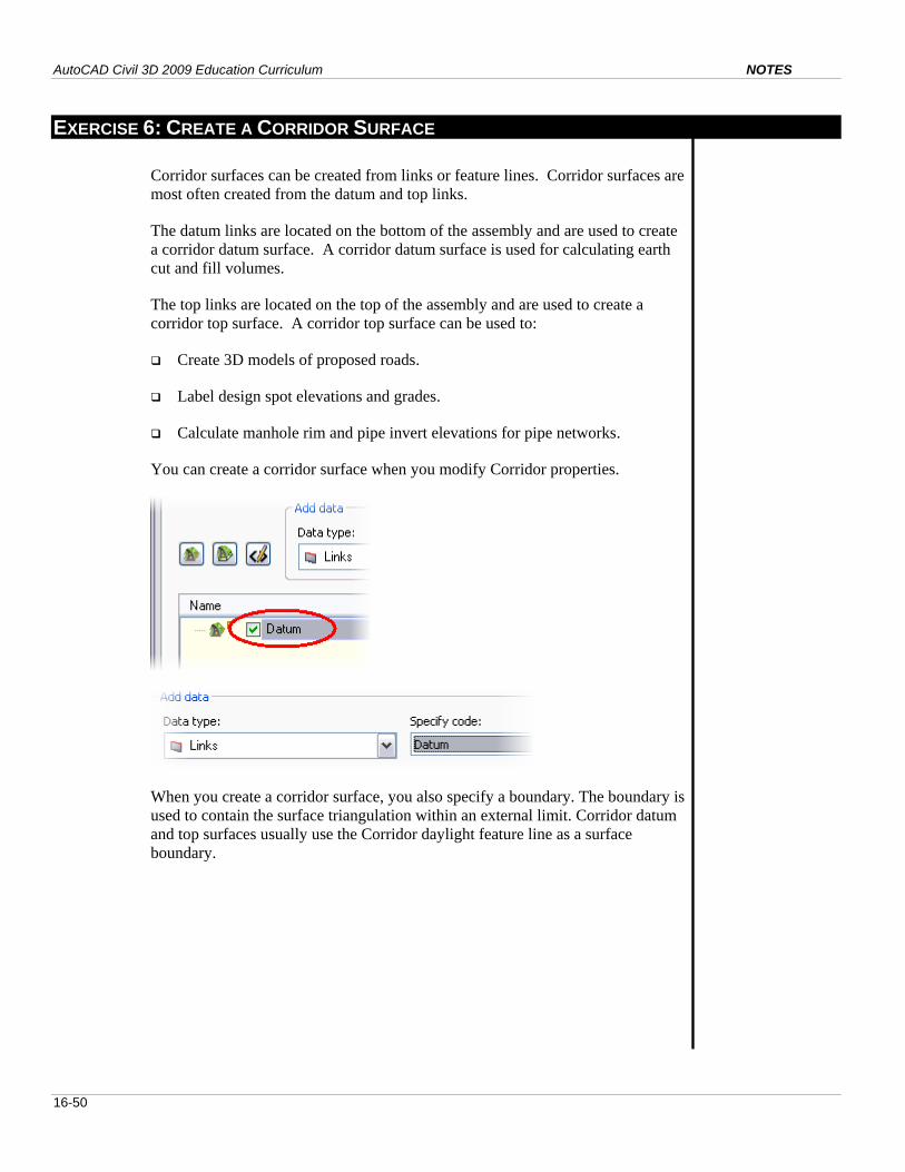
Corridor surfaces can be created from links or feature lines. Corridor surfaces are
most often created from the datum and top links.
The datum links are located on the bottom of the assembly and are used to create
a corridor datum surface. A corridor datum surface is used for calculating earth
cut and fill volumes.
The top links are located on the top of the assembly and are used to create a
corridor top surface. A corridor top surface can be used to:
Create 3D models of proposed roads.
Label design spot elevations and grades.
Calculate manhole rim and pipe invert elevations for pipe networks.
You can create a corridor surface when you modify Corridor properties.
When you create a corridor surface, you also specify a boundary. The boundary is
used to contain the surface triangulation within an external limit. Corridor datum
and top surfaces usually use the Corridor daylight feature line as a surface
boundary.

Module 16 - Roadway Assemblies and Corridors NOTES
16-51
In this exercise, you create Corridor top and datum surfaces.
For this exercise, open …\Module 16 – Roadway Assemblies and Corridors\
I_RoadwayAssembliesandCorridors-EX6.dwg
(M_RoadwayAssembliesandCorridors-EX6.dwg).
First, create a corridor surface for the datum.
1. Click the Prospector tab in the Toolspace window.
2. Expand the Corridors tree.
3. Right-click 8th Avenue corridor. Click Properties.
4. In the Corridor Properties dialog box, click the Surfaces tab.
5. Click Create a Corridor Surface.
6. Change the name to Datum.

AutoCAD Civil 3D 2009 Education Curriculum NOTES
16-52
Now select the data to be used for the surface.
7. Ensure Data Type is Links.
8. For Code, select Datum.
9. Click Add Surface Item.
10. In the Pick Corridor Surface Style dialog box, select _Grid.
11. Click OK.
Civil 3D creates the corridor datum surface and displays it using the _Grid
Surface Style.

Module 16 - Roadway Assemblies and Corridors NOTES
16-53
Notice that the surface extends beyond the limit of the daylight lines.
An outer boundary is required to limit the surface extents to the daylight
lines. You define a boundary in the next few steps.
12. In Prospector, right-click 8th Avenue Corridor. Click Properties.
13. In the Corridor Properties dialog box, click the Boundaries tab.
14. Right-click Datum. Click Add Automatically > Daylight.
Civil 3D uses the Daylight feature lines as an outside boundary for the datum
surface.
15. Click OK.
Civil 3D displays the surface correctly.

AutoCAD Civil 3D 2009 Education Curriculum NOTES
16-54
Now create a corridor surface representing the top or finished surface. You
follow the same procedures used to create the corridor datum surface.
16. Click the Prospector tab in the Toolspace window.
17. Expand the Corridors tree.
18. Right-click 8th Avenue Corridor. Click Properties.
19. In the Corridor Properties dialog box, click the Surfaces tab.
First suppress the display of the corridor datum surface.
20. For Datum Surface, change Surface Style to _No Display.
Now create the Top surface.
21. Click Create a Corridor Surface.
22. Change the name of the new surface to Top.
23. Ensure Data Type is Links.
24. For Code, select Top.
25. Click Add Surface Item.
26. For Top surface, change the Surface Style to _No Display.

Module 16 - Roadway Assemblies and Corridors NOTES
16-55
Now add Outer Boundary for the Top surface.
27. Click the Boundaries tab.
28. Right-click Top. Click Add Automatically > Daylight.
29. Click OK.
Civil 3D creates the Top Corridor surface.
Note: The Top and Datum surfaces are not shown because they were
assigned the _No Display surface style.
30. Close the drawing and do not save the changes.

AutoCAD Civil 3D 2009 Education Curriculum NOTES
16-56
EXERCISE 7: PREPARE 3D MODEL OF FINISHED ROAD DESIGN
In this exercise, you create a 3D model of the completed road design. The 3D
model is represented by a surface that combines both existing ground surface data
and proposed corridor top surface data.
You first create an EG FG Combined surface.
The EG FG Combined surface is then modified by pasting the Existing Ground
surface and the corridor top. The Paste command combines the data from the two
surfaces.
In the final steps of this exercise, you assign a Code Set Style to the corridor links
that includes render materials.

Module 16 - Roadway Assemblies and Corridors NOTES
16-57
You can create photorealistic renderings of the corridor without creating corridor
surfaces.
For this exercise, open …\Module 16 – Roadway Assemblies and Corridors\
I_RoadwayAssembliesandCorridors-EX7.dwg
(M_RoadwayAssembliesandCorridors-EX7.dwg).

AutoCAD Civil 3D 2009 Education Curriculum NOTES
16-58
Create the EG FG Combined Surface
1. In Toolspace, click the Prospector tab.
2. Right-click Surfaces. Click Create Surface.
3. In the Create Surface dialog box:
For Name, enter EG FG Combined.
Change the Surface style to Contours 1’ and 5’ (Background) (Contours 1
m and 5 m (Background).
4. Click Apply.
5. Click OK.
Now suppress the display of the Existing Ground surface.
6. In Prospector, click Surfaces.
7. In the Item View area at the bottom of Toolspace, change Existing Ground
Style to _No Display.

Module 16 - Roadway Assemblies and Corridors NOTES
16-59
Paste the Existing Ground and Corridor Top Surface Into the EG FG
Combined Surface
1. In Prospector, expand the Surfaces, EG FG Combined, and Definition Trees
trees.
2. Right-click Edits. Click Paste Surface.
3. In the Select Surface to Paste dialog box, with the CTRL key pressed, select
Existing Ground and Top.
4. Click OK.
Civil 3D pastes the 8th Avenue Corridor Top Surface into the EG FG
Combined Surface.
5. Zoom to the 8th Avenue Corridor near the middle of the curve.

AutoCAD Civil 3D 2009 Education Curriculum NOTES
16-60
Notice how the contours reflect the design elevations for 8th Avenue inside the
corridor daylight lines and the existing surface elevations outside the corridor
daylight lines.
6. In the drawing area, select the EG FG Combined Surface.
7. Click the surface. Right-click and click Object Viewer.
Civil 3D displays the surface in the Object Viewer.
8. In the Object Viewer, change the display mode to 3D Wireframe.
9. Use the tools in the Object Viewer to display the EG FG Combined in 3D.

Module 16 - Roadway Assemblies and Corridors NOTES
16-61
10. Close the Object Viewer.
Assign Render Material Styles to Corridor and Surface
1. In the drawing area, select the corridor.
2. Right-click and click Corridor Properties.
3. In the Corridor Properties dialog box, click the Codes tab.
4. Change the Code Set Style to Rural Corridor Rendered.
5. Click OK.
Now assign a render material to the EG FG Combined surface.
6. In the drawing area, click the surface.
7. Right-click and click Surface Properties.
8. In the Surface Properties dialog box, click the Information tab.
9. Change Render Material to Sitework.Planting.Grass.Short.
The Render Material applies if you render the Existing Ground surface model.
10. Click OK.
11. In the drawing area, click the 8th Avenue Corridor.

AutoCAD Civil 3D 2009 Education Curriculum NOTES
16-62
12. Right-click and click Object Viewer.
13. Change the display mode to Realistic.
14. Change the view to SW Isometric.
Civil 3D displays the rendered corridor and surface.
15. Experiment with other views in the Object Viewer.
16. Close the Object Viewer.
17. Close the drawing and do not save the changes.

Module 16 - Roadway Assemblies and Corridors NOTES
16-63
Questions
1. What is the procedure for working with subassemblies to create an
assembly?
2. Why would you rename a subassembly on the tool palette?
3. What are subassembly input parameters used for?
4. What controls the display of subassembly and corridor points, links, and
shapes?
5. What are corridor feature lines and how are they created?
6. What can subassembly points be used for?
7. What can subassembly links be used for?
8. Why would you create a corridor top surface?
9. Why would you create a corridor datum surface?
10. What is target mapping?
Answers
1. You copy the desired subassemblies from the Subassembly Catalog to the
tool palette. You then modify the properties of the subassemblies on the
tool palette. Assemblies are created by adding subassemblies from the tool
palette to the assembly object.
2. You rename a subassembly on a tool palette to offer a simplified name to
the cross section elements.
3. Subassembly input parameters are used to vary the geometric properties of
the subassembly. Examples of input parameters include width, slope,
grade, depth, and material.
4. A marker style controls the display of subassembly/corridor points. A link
style controls the display of subassembly links and a shape style controls
the display of subassembly shapes.
5. The corridor feature lines are the longitudinal lines along the corridor.
They are created by connecting the subassembly points.
6. Subassembly points are used to create the corridor feature lines, annotate
offsets and elevations on design sections, and create Civil 3D points that
can be used for construction staking.

AutoCAD Civil 3D 2009 Education Curriculum NOTES
16-64
7. Subassembly links can be used to create top and datum corridor surfaces,
annotate slopes and grades on design cross sections, and assign render
materials for photorealistic rendering.
8. Corridor top surfaces are used to create 3D models of a proposed road or
highway. They can also be used to calculate manhole rim and invert
elevations for storm and sanitary sewer networks.
9. A corridor datum surface is used to calculate earth cut and fill volumes.
10. Target mapping is the process of assigning targets to the subassemblies
when you create a corridor. For example, the daylight subassemblies use
required targets to indicate which surface to project the match slope. The
lane and shoulder subassemblies use optional targets to control widths with
alignments.

Module 16 - Roadway Assemblies and Corridors NOTES
16-65
Module Summary
In this module, you learned how to work with subassemblies, assemblies, and
corridors in AutoCAD Civil 3D. Subassemblies and their associated Help
documents were analyzed in the Subassembly Catalog. A tool palette was
created and the subassemblies were copied to the tool palette. The input
parameters for the subassemblies were modified and the subassemblies were
renamed on the tool palette.
You then created an assembly representing a typical section from the
subassemblies. You modified the assembly to apply meaningful names to the
assembly components.
The next step was to create the corridor model from the assembly. The
corridor model was created by specifying a design alignment, profile, and
assembly. After the corridor was created, you then modified the corridor
properties to change the station limits for the region and change the assembly
insertion frequencies.
The final steps in the module included building a top and datum corridor
surface, and creating and viewing a 3D model of the final road configuration.