Module 06 - West Virginia Universityddean/CE210/AutoCAD Ci… · · 2008-05-07Module 06 Surfaces...
38
NOTES Module 06 Surfaces In this module, you learn how to work with surfaces in AutoCAD Civil 3D. Surfaces are three-dimensional objects used to represent both existing and proposed terrain conditions. The display of a surface is controlled with a surface style. Surfaces can be displayed with different components including contours, triangles, and points. Surfaces can also be annotated with contour elevations, spot elevations, and slopes. Engineers usually display existing terrain surfaces on their plans with contours. During the design process, engineers regularly work with existing terrain surfaces. These are used to check the interaction between the proposed design and the existing terrain. Engineers also create surfaces representing proposed conditions during the design process. These surfaces are used to help visualize the design, calculate material quantities, and to generate data required for construction staking. Objectives After completing this module, you will be able to: Describe how surfaces are used in the site development process. Create surface styles to control surface display. Set the default style and naming template for surfaces. Create a surface using points and breaklines. Modify the surface properties. Edit a surface. Assign a contour style to a surface and apply surface labels. Export a surface to Google Earth. Import an image from Google Earth. Drape an image on a surface and use the object viewer.
Transcript of Module 06 - West Virginia Universityddean/CE210/AutoCAD Ci… · · 2008-05-07Module 06 Surfaces...

NOTES
Module 06
Surfaces
In this module, you learn how to work with surfaces in AutoCAD Civil 3D.
Surfaces are three-dimensional objects used to represent both existing and
proposed terrain conditions.
The display of a surface is controlled with a surface style. Surfaces can be
displayed with different components including contours, triangles, and points.
Surfaces can also be annotated with contour elevations, spot elevations, and
slopes. Engineers usually display existing terrain surfaces on their plans with
contours.
During the design process, engineers regularly work with existing terrain
surfaces. These are used to check the interaction between the proposed design
and the existing terrain. Engineers also create surfaces representing proposed
conditions during the design process. These surfaces are used to help visualize
the design, calculate material quantities, and to generate data required for
construction staking.
Objectives
After completing this module, you will be able to:
Describe how surfaces are used in the site development process.
Create surface styles to control surface display.
Set the default style and naming template for surfaces.
Create a surface using points and breaklines.
Modify the surface properties.
Edit a surface.
Assign a contour style to a surface and apply surface labels.
Export a surface to Google Earth.
Import an image from Google Earth.
Drape an image on a surface and use the object viewer.

AutoCAD Civil 3D 2009 Education Curriculum NOTES
06-2
Notes
Data for this module resides in the \AutoCAD Civil 3D 2009 Education
Curriculum\Module 06 - Surfaces\ folder.
You will also require Google Earth and a live Internet connection for the last
few exercises in this lesson.
Student Exercises
The following exercises are provided in step-by-step format. Open the Civil
3D program prior to beginning the lesson by double-clicking the Civil 3D icon
on your desktop.
You working in the Imperial system should use the drawing files beginning
with the letter I, while those working in the metric system should use the
drawing files beginning with the letter M. You are provided with a drawing for
each exercise in the lesson.
You must use the drawings provided with the exercises.
The exercises in this module are as follows:
1. Create Surface Styles
2. Set the Default Surface Style and Naming Template
3. Create a Surface
4. Modify the Surface Properties
5. Edit a Surface
6. Assign a Contour Style and Apply Surface Labels
7. Export a Surface to Google Earth
8. Import an Image from Google Earth
9. Drape an Image on a Surface
Module 06 - Surfaces NOTES
06-3
Surfaces
Surfaces play a very important role in civil engineering and site development
projects. Surfaces are used to represent the three-dimensional nature of the
existing topography and the proposed design.
There are many ways to represent surfaces in a CAD environment. Civil 3D
uses a TIN (Triangulated Irregular Network) to represent a surface. A TIN is
usually created from points, breaklines, or contour data. In this Module, you
create surfaces from points and breaklines.
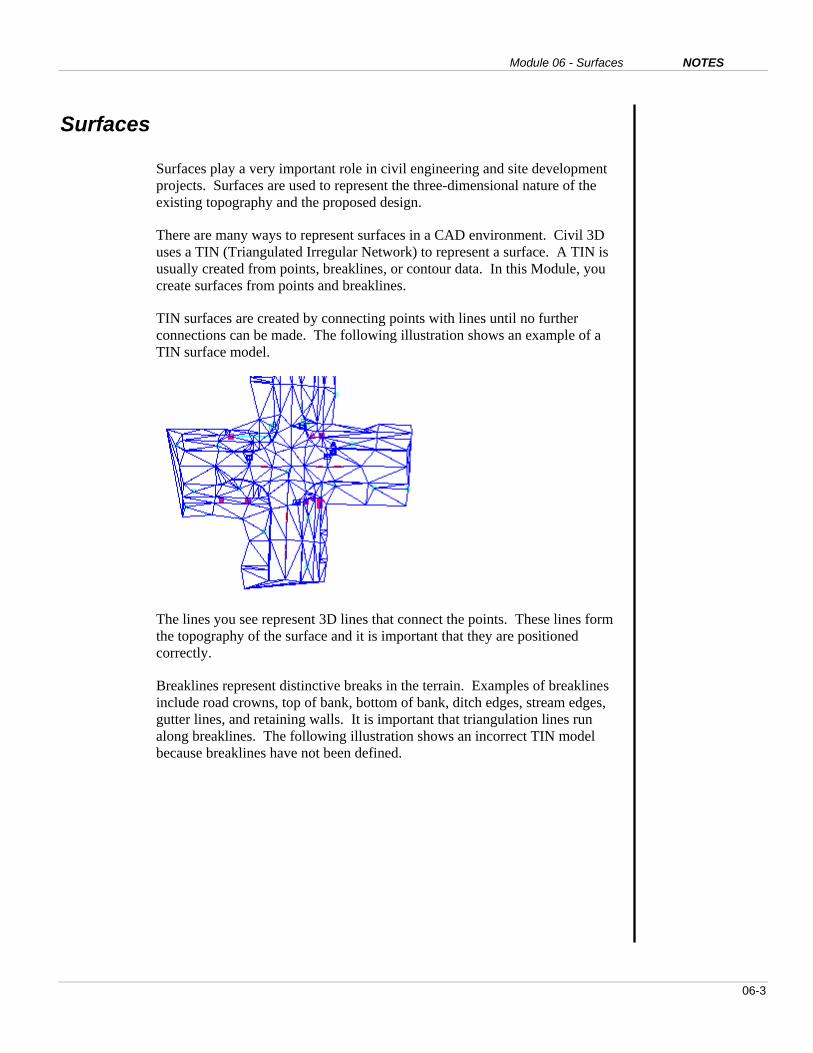
TIN surfaces are created by connecting points with lines until no further
connections can be made. The following illustration shows an example of a
TIN surface model.
The lines you see represent 3D lines that connect the points. These lines form
the topography of the surface and it is important that they are positioned
correctly.
Breaklines represent distinctive breaks in the terrain. Examples of breaklines
include road crowns, top of bank, bottom of bank, ditch edges, stream edges,
gutter lines, and retaining walls. It is important that triangulation lines run
along breaklines. The following illustration shows an incorrect TIN model
because breaklines have not been defined.

AutoCAD Civil 3D 2009 Education Curriculum NOTES
06-4
In the previous illustration, notice that the triangulation lines do not run along,
but pass over sidewalks, pavement edges, and road crowns. This means that
the surface is not accurate.
After defining these features as breaklines in Civil 3D, the TIN appears as
follows:
Notice that the triangulation lines now run directly over the breaks in the
terrain, such as sidewalks and road crowns. This is an accurate surface model.
Surface styles are used to control the display of the surface. Surface styles can
be used to show the surface as triangles, contours, grids, points, and borders.
Once a surface has been created, you can assign a surface style to change the
display of the surface. Engineers typically use surface styles that display
triangles when creating surfaces and surface styles that display contours when
creating engineering drawings.
Once the surface has been created you can label spot elevations, slopes, and
contours. You can also export data to and from Google Earth. This is
discussed in the last few exercises of this module.

Module 06 - Surfaces NOTES
06-5
Key Terms
DTM Digital Terrain Model. A digital terrain model is another name for a surface.
TIN Triangulated Irregular Network. AutoCAD Civil 3D uses a TIN to represent
surface models. A TIN is created by connecting point with closest proximity.
Breakline Breaklines represent distinct terrain breaks. Examples of breaklines include
road crowns, gutters, top of bank, bottom of bank, ditch edges, stream edges,
and sidewalk edges. When creating surfaces, breaklines must be defined.
Triangulation lines are forced to “break” the terrain and run over the length of
defined breaklines. Triangulation lines can not cross over breaklines.
Proximity
Breakline
A proximity breakline is defined from 2D polylines. Proximity breaklines
assign elevations by physically relocating the polyline vertices to the nearest
surface data point. 2D polylines created with vertices at the point nodes do not
relocate.
Contour A contour line connects points of constant elevation. Contour lines are created
by connecting locations on triangulation lines with the same elevation.
Surface
Style
The surface style controls the display of the surface. Surface styles can be
used to display surfaces as triangles, points, contours, borders or grids. You
can also create surface styles to suppress the display of a surface. This is
especially useful when working with large surfaces.
Naming
Template
Naming templates are used in AutoCAD Civil 3D to automatically assign
names to newly created objects. Naming templates are useful when large
amounts of civil engineering data are being created. They help organize the
data in the drawing. Users can override the names automatically assigned with
naming templates.
Invalid
DTM Points
Invalid DTM Points are excluded from point groups used to create surface
models. These points do not represent true surface elevations. Typical
examples include sewer inverts and tops of fire hydrants.
Earth
Google Earth is a popular geospatial application made by Google. Google
Earth allows you to view aerial photographs and other data anywhere on the
surface of the earth. You can download Google Earth by visiting
earth.google.com.

AutoCAD Civil 3D 2009 Education Curriculum NOTES
06-6
EXERCISE 1: CREATE SURFACE STYLES
A surface is a singular object in Civil 3D. The display of a surface is
controlled using a surface style. Surfaces styles can be used to display the
surface as points, triangles, borders, contours, and grids.
In this exercise, you create two surface styles.
For this exercise, open …\Module 06 – Surfaces\I_Surfaces-EX1.dwg
(M_Surfaces-EX1.dwg).
1. Click the Settings tab of the Toolspace Window.
2. Click the plus signs (+) to expand the Surface and Surface Styles tree.
Two surface styles are available for use.
3. Right-click Surface Styles and click New.
4. For Name, enter Triangles. Click Apply.
5. Click the Display tab.
6. Turn off all component types by clicking the lightbulb symbol.

Module 06 - Surfaces NOTES
06-7
7. Turn on Triangles.
8. Change the color of Triangles to Blue (color 5).
9. Click the Triangles tab and review the settings.
Notice that you can assign independent display properties to the surface
components in either Plan (2D), Model (3D), and Section views.
10. Click OK.
You do not see the triangles yet because the surface has not been created.
Now create a surface style to show major and minor contours.
11. Right-click the Surface Styles tree.
12. Click New.
13. Enter 1’ and 5’ Existing (Metric: 0.5m and 2m Existing).
14. Click Apply.
15. Click the Display tab.
16. Turn everything off except Major Contour and Minor Contour.
17. Change the color of Major Contour to green (color 3).
18. Change the color of Minor Contour to grey (color 8).

AutoCAD Civil 3D 2009 Education Curriculum NOTES
06-8
19. Click the Contours tab.
20. Click the plus sign (+) to expand the Contour Intervals tree.
21. Change the Minor interval to 1’ (Metric: .5m). Press ENTER.
22. Change the Major interval to 5’ (Metric: 2m). Press ENTER.
23. Click the plus sign (+) to expand Contour Smoothing.
24. For Smooth Contours, select True.
25. At the bottom of the dialog box, increase the smoothing factor by sliding
the bar all the way to the right.
26. Click OK.
Now review the _No Display and Contours and Triangles surface styles.
27. Right-click _No Display and select Edit.

Module 06 - Surfaces NOTES
06-9
28. Click the Display tab.
Notice that all of the components are not visible. The _No Display surface
style can be assigned to surfaces to suppress their display.
29. Click Cancel.
30. Right-click Contours and Triangles and select Edit.
31. Click the Display tab.
Notice that the Triangles, Border, Major Contour, and Minor Contour
components are visible. This surface style is used when editing a surface.
32. Click Cancel.
33. Close the drawing and do not save the changes.
AutoCAD Civil 3D 2009 Education Curriculum NOTES
06-10
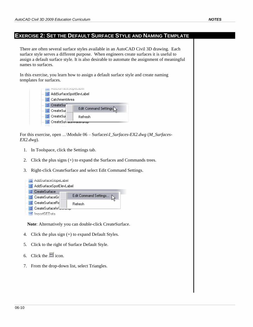
EXERCISE 2: SET THE DEFAULT SURFACE STYLE AND NAMING TEMPLATE
There are often several surface styles available in an AutoCAD Civil 3D drawing. Each
surface style serves a different purpose. When engineers create surfaces it is useful to
assign a default surface style. It is also desirable to automate the assignment of meaningful
names to surfaces.
In this exercise, you learn how to assign a default surface style and create naming
templates for surfaces.
For this exercise, open …\Module 06 – Surfaces\I_Surfaces-EX2.dwg (M_Surfaces-
EX2.dwg).
1. In Toolspace, click the Settings tab.
2. Click the plus signs (+) to expand the Surfaces and Commands trees.
3. Right-click CreateSurface and select Edit Command Settings.
Note: Alternatively you can double-click CreateSurface.
4. Click the plus sign (+) to expand Default Styles.
5. Click to the right of Surface Default Style.
6. Click the icon.
7. From the drop-down list, select Triangles.

Module 06 - Surfaces NOTES
06-11
8. Click OK.
Notice that the default surface style is set to triangles.
Now you change the default naming template for the surface.
9. Click the plus sign (+) to expand Default Name Format.
10. Click to the right of Surface Name Template.
11. Click the icon.
12. For Name, enter EG.
13. Click Insert.
14. In the Incremental Number Format section of the dialog box, change the Starting
number to 1.
15. Click OK.
16. Click OK again to close the Edit Command Settings dialog box.
When a new surface is created, it uses the Triangles surface style and is named EG1,

AutoCAD Civil 3D 2009 Education Curriculum NOTES
06-12
EG2, etc.
17. Close the drawing and do not save the changes.

Module 06 - Surfaces NOTES
06-13
EXERCISE 3: CREATE A SURFACE
In this exercise, you create a surface from points and breaklines. A point group for surface
modeling exists in the drawing. This point group excludes the points that are not suitable
for surface modeling, such as tops of fire hydrants and survey monument data. Breaklines
are created using the proximity breakline definition method.
For this exercise, open …\Module 06 – Surfaces\I_Surfaces-EX3.dwg (M_Surfaces-
EX3.dwg).
Begin by reviewing the surface modeling point group.
1. In Toolspace, click the Prospector tab.
2. Click the plus sign (+) to the left of Point Groups.
3. Right-click EG Surface and click Properties.
4. Click the Exclude tab.
Notice the exclusions of MON*, LP, FH*. Points with raw descriptions matching these
values do not represent the elevation of the existing topography and are excluded from
the surface.
5. Click Cancel.
Now create the surface.
6. Right-click Surfaces and click Create Surface.
7. For Description, enter Existing Ground Topo. Press ENTER.
AutoCAD Civil 3D 2009 Education Curriculum NOTES
06-14
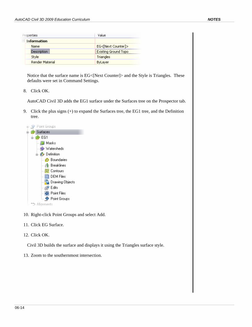
Notice that the surface name is EG<[Next Counter]> and the Style is Triangles. These
defaults were set in Command Settings.
8. Click OK.
AutoCAD Civil 3D adds the EG1 surface under the Surfaces tree on the Prospector tab.
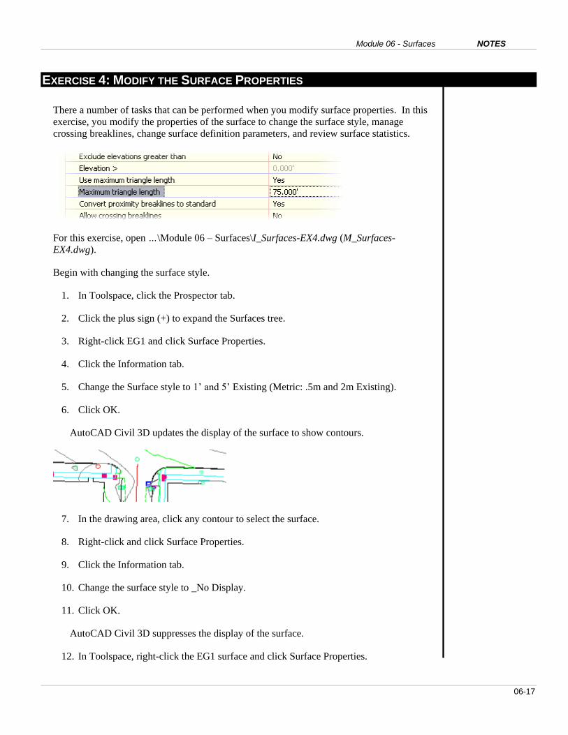
9. Click the plus signs (+) to expand the Surfaces tree, the EG1 tree, and the Definition
tree.
10. Right-click Point Groups and select Add.
11. Click EG Surface.
12. Click OK.
Civil 3D builds the surface and displays it using the Triangles surface style.
13. Zoom to the southernmost intersection.

Module 06 - Surfaces NOTES
06-15
Look closely at the triangulation and the base plan line work. All the polylines on the
base plan represent terrain breaks. The triangulation lines, however, do not follow over
the base plan polylines.
14. Navigate other areas in the drawing and make the same observation.
Next, you define breaklines to force the triangulation along the terrain breaks.
15. Under the Definition tree, right-click Breaklines and click Add.
16. In the Add Breaklines dialog box, for Description, enter Proximity Breaklines.
17. For Type, select Proximity.
Proximity breaklines are defined from 2D (plan view) polylines. When defining
proximity breaklines, elevations are assigned to the polyline vertices by relocating each
polyline vertex to the nearest surface data point, and the point elevation is assigned to
the vertex. Most vertices are drawn to the points, so vertices do not move but the point
elevation is assigned.
18. Click OK.
19. Window-select the entire drawing to select all 2D polylines. Press ENTER.

AutoCAD Civil 3D 2009 Education Curriculum NOTES
06-16
The EG1 surface automatically updates. Notice that the triangulation lines follow
directly over the base plan polylines. This indicates that all breaklines have been
defined.
You may receive some warning and error messages in the Event Viewer of the
Panorama window.
20. Review the warning and error messages in the Event Viewer.
The error messages indicate instances of crossing breaklines. These errors indicate the
locations where two breaklines shared the same point and are addressed in the next
exercise.
21. In the Panorama window, click Action > Clear All Events.
22. Close the Panorama window.
23. Close the drawing and do not save the changes.
Module 06 - Surfaces NOTES
06-17
EXERCISE 4: MODIFY THE SURFACE PROPERTIES
There a number of tasks that can be performed when you modify surface properties. In this
exercise, you modify the properties of the surface to change the surface style, manage
crossing breaklines, change surface definition parameters, and review surface statistics.
For this exercise, open …\Module 06 – Surfaces\I_Surfaces-EX4.dwg (M_Surfaces-
EX4.dwg).
Begin with changing the surface style.
1. In Toolspace, click the Prospector tab.
2. Click the plus sign (+) to expand the Surfaces tree.
3. Right-click EG1 and click Surface Properties.
4. Click the Information tab.
5. Change the Surface style to 1’ and 5’ Existing (Metric: .5m and 2m Existing).
6. Click OK.
AutoCAD Civil 3D updates the display of the surface to show contours.
7. In the drawing area, click any contour to select the surface.
8. Right-click and click Surface Properties.
9. Click the Information tab.
10. Change the surface style to _No Display.
11. Click OK.
AutoCAD Civil 3D suppresses the display of the surface.
12. In Toolspace, right-click the EG1 surface and click Surface Properties.

AutoCAD Civil 3D 2009 Education Curriculum NOTES
06-18
13. Click the Information tab.
14. Change the Surface style back to Triangles.
15. Click Apply.
16. Click the Definition tab.
17. Click the plus sign (+) to expand the Build tree.
18. For Use Maximum Triangle Length, change the value to Yes.
19. For Maximum Triangle Length, enter 75’ (25 m). Press ENTER.
20. For Allow Crossing Breaklines, change the value to Yes.
21. For Elevation to Use, select Use Average Breakline Elevation at Intersection.
This eliminates the crossing breaklines processing error you encountered earlier.
22. Click OK
23. In the Surface Properties – Rebuild Surface dialog box, click Rebuild the Surface.
All triangles shorter than 75’ (25m) are removed. This is useful to delete long
unwanted triangles near the perimeter of the surface. The crossing breaklines warnings
have also been resolved.
The statistics of a TIN can be revealing.
24. In Toolspace, right-click the EG1 surface and click Surface Properties.
25. Click the Statistics tab.
26. Click the plus sign (+) to expand the General tree.

Module 06 - Surfaces NOTES
06-19
Note the elevation statistics for the surface. Your statistics may be slightly different.
27. Click the plus sign (+) to expand the Extended and TIN trees, and review the other
surface statistics.
28. Click Cancel.
29. Close the drawing and do not save the changes.

AutoCAD Civil 3D 2009 Education Curriculum NOTES
06-20
EXERCISE 5: EDIT A SURFACE
After a surface has been created, there is often a need to perform further edits on the
surface to ensure the triangulation lines are correct. There are a number of edits that can
be performed on a surface.
In this exercise, you learn how to add a line, delete a line, and flip a face.
For this exercise, open …\Module 06 – Surfaces\I_Surfaces-EX5.dwg (M_Surfaces-
EX5.dwg).
1. Zoom to the extents of the drawing.
Notice that in the vicinity of the intersections, some longer triangles remain that span
across the corners.
Module 06 - Surfaces NOTES
06-21
These triangles are not accurate and will result in the incorrect display of contours.
2. Zoom to the southernmost intersection where you see these spanning triangulation
lines.
3. Click the surface in the drawing. Right-click and click Surface Properties.
4. Click the Information tab.
5. Change the surface style to Contours and Triangles.
6. Click OK.
Note the display of the contours and triangulation lines.
You may need to modify the Contours and Triangles surface style to set
distinguishing colors based on the color of your graphics background.
Hint: To do this, click the surface, right-click and click Edit Surface Style. Then
click the Display tab to change the colors.
7. In Toolspace, click the Prospector tab.
8. Click the plus sign (+) to expand the Surfaces, EG1, and Definition trees.
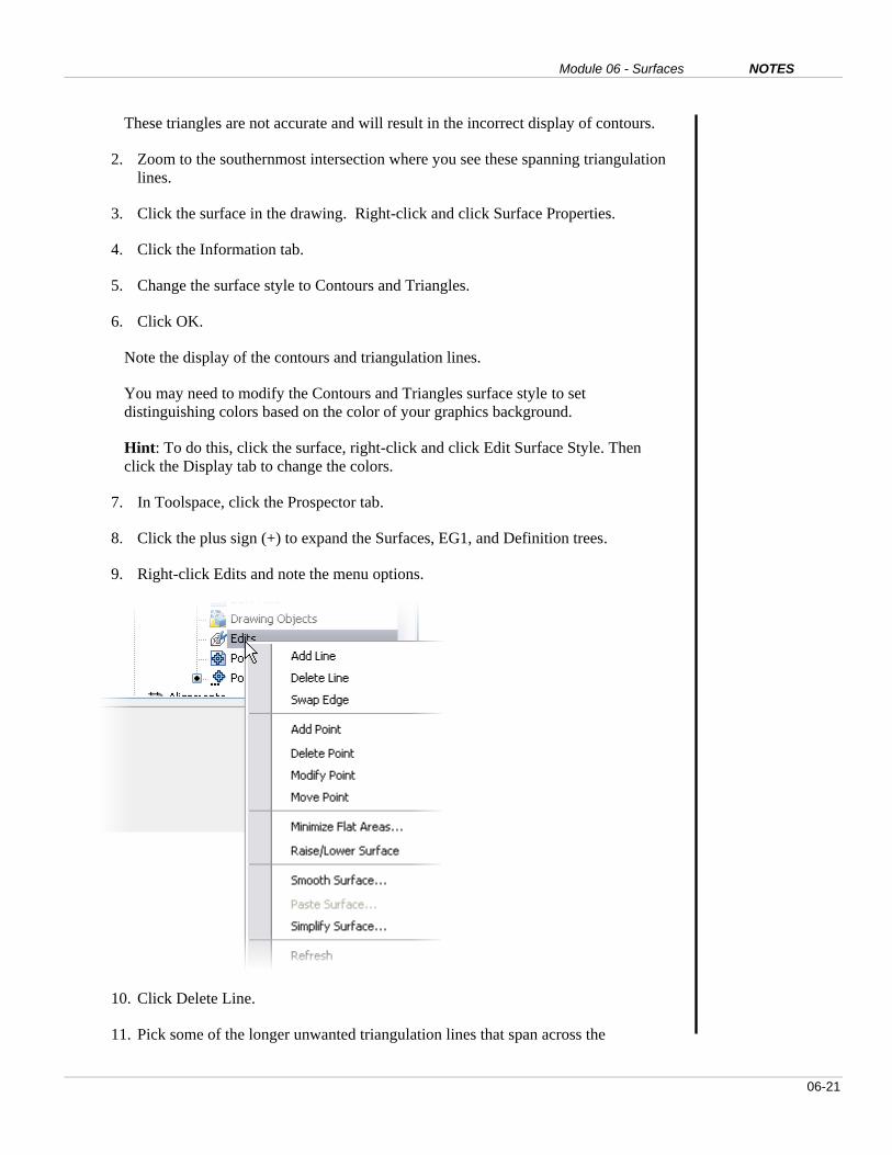
9. Right-click Edits and note the menu options.
10. Click Delete Line.
11. Pick some of the longer unwanted triangulation lines that span across the

AutoCAD Civil 3D 2009 Education Curriculum NOTES
06-22
intersection corners. Press ENTER twice when done.
Hint: You can use any AutoCAD selection set option such as crossing and fence.
Notice how the contours automatically update to reflect the surface changes.
12. Right-click Edits again.
13. Click Swap Edge.
14. Pick a triangulation line with a contour passing through it. Press ENTER when
done.
Notice how the edge reorients itself in the opposite direction. If there is a contour
present, it will also readjust based on the position of the triangle.
15. Right-click Edits again.
16. Click Add Line.
You add a line to expand the extent of surface data.
17. Graphically pick the endpoints of two existing triangulation lines near the
perimeter of the surface. Press ENTER when done.
AutoCAD Civil 3D adds a line and if necessary, display an additional contour.
18. Click the Edits tree for the EG1 surface.
Notice the list of edits in the Item View area below.
19. Right-click any of the edits in the Item View area.
Notice that you can remove any unwanted edits by clicking Delete.
20. If you have time, use these three commands to finish editing the EG1 surface.
21. Close the drawing and do not save the changes.

Module 06 - Surfaces NOTES
06-23
EXERCISE 6: ASSIGN A CONTOUR STYLE AND APPLY SURFACE LABELS
In this exercise, you learn how to apply contour labels, spot elevation labels,
and slope labels to a surface. Surface labels automatically update if the surface
changes.
For this exercise, open …\Module 06 – Surfaces\I_Surfaces-EX6.dwg
(M_Surfaces-EX6.dwg).
Before you begin, turn off the points layer.
1. Enter LA (Layer). Press ENTER.
2. In the Layer Properties Manager window, turn off the following layers:
V-NODE
V-NODE-TXT
3. Click the surface in the drawing area.
4. Right-click and click Surface Properties.
5. Click the Information tab.
6. Change the surface style to: 1’ and 5’ Existing (Metric: .5m and 2m
Existing).
7. Click OK.
8. Zoom to the area south of the southern most intersection.
9. Select Surfaces > Add Surface Labels > Add Surface Labels.
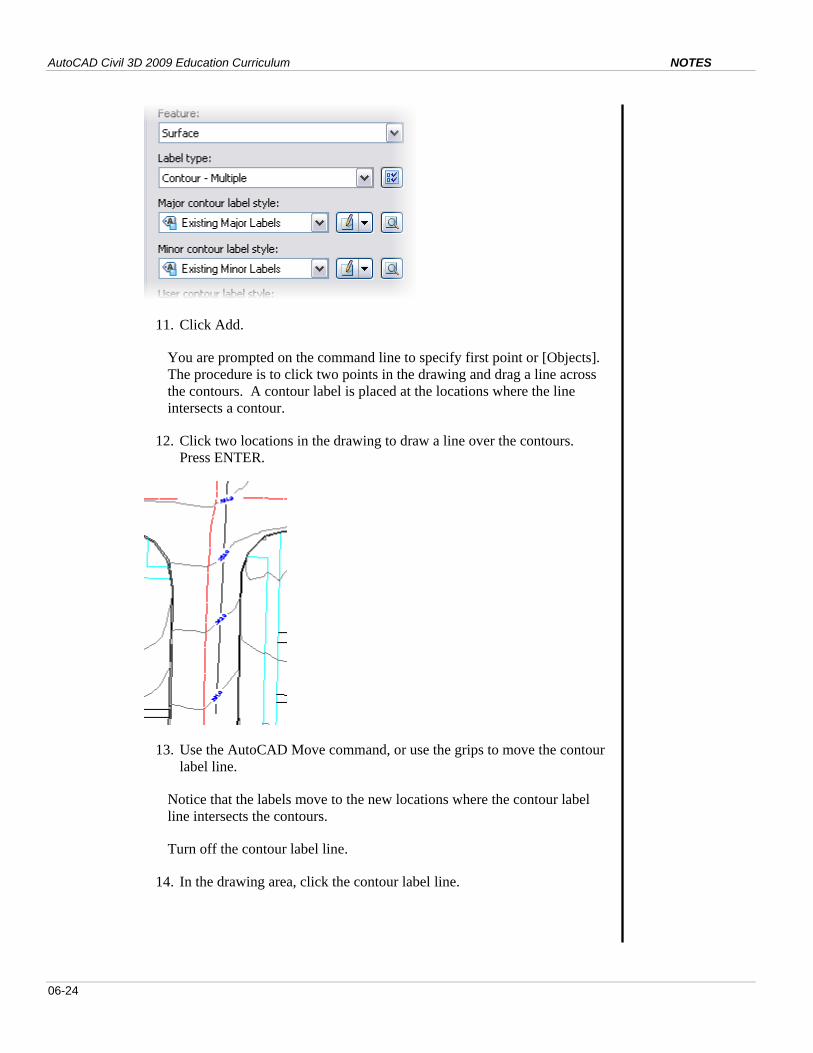
10. In the Add Labels dialog box, for Label Type, select Contour – Multiple.
AutoCAD Civil 3D 2009 Education Curriculum NOTES
06-24
11. Click Add.
You are prompted on the command line to specify first point or [Objects].
The procedure is to click two points in the drawing and drag a line across
the contours. A contour label is placed at the locations where the line
intersects a contour.
12. Click two locations in the drawing to draw a line over the contours.
Press ENTER.
13. Use the AutoCAD Move command, or use the grips to move the contour
label line.
Notice that the labels move to the new locations where the contour label
line intersects the contours.
Turn off the contour label line.
14. In the drawing area, click the contour label line.
Module 06 - Surfaces NOTES
06-25
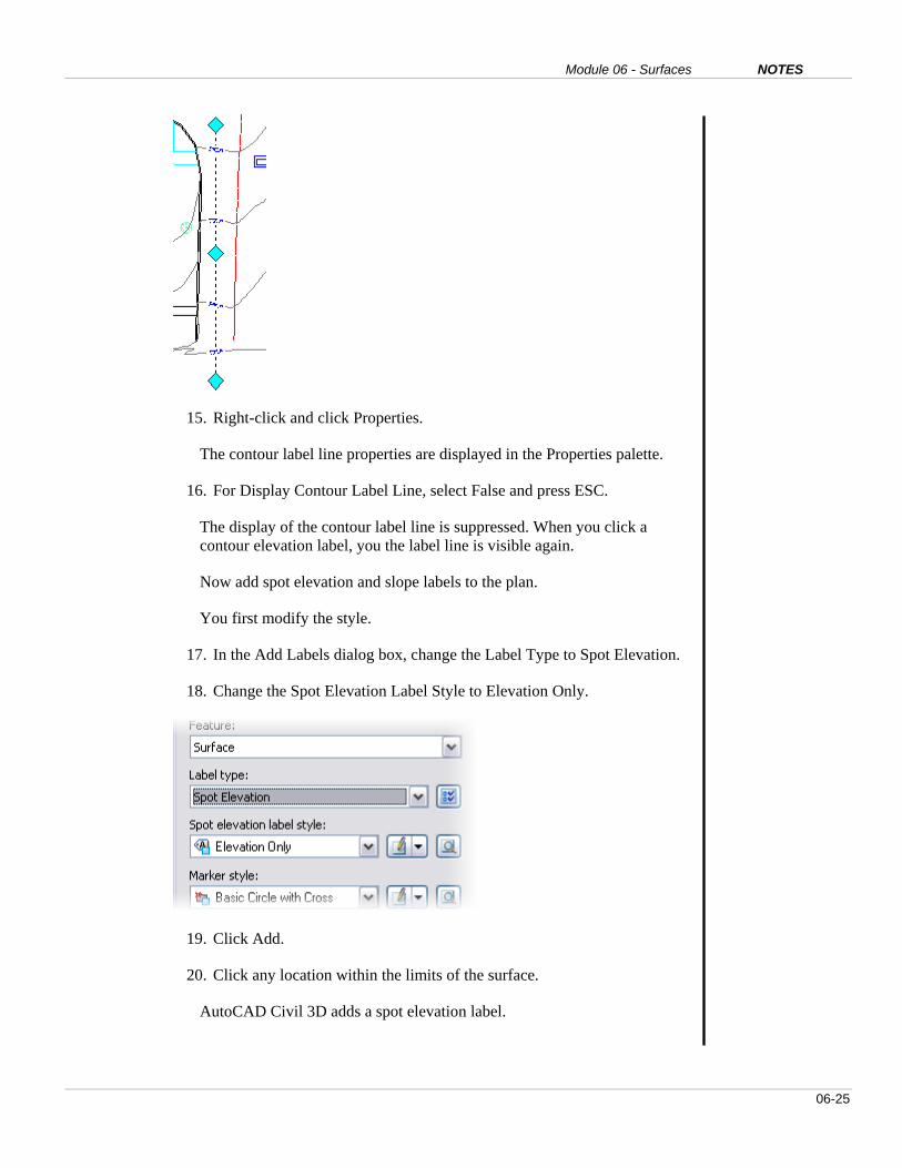
15. Right-click and click Properties.
The contour label line properties are displayed in the Properties palette.
16. For Display Contour Label Line, select False and press ESC.
The display of the contour label line is suppressed. When you click a
contour elevation label, you the label line is visible again.
Now add spot elevation and slope labels to the plan.
You first modify the style.
17. In the Add Labels dialog box, change the Label Type to Spot Elevation.
18. Change the Spot Elevation Label Style to Elevation Only.
19. Click Add.
20. Click any location within the limits of the surface.
AutoCAD Civil 3D adds a spot elevation label.

AutoCAD Civil 3D 2009 Education Curriculum NOTES
06-26
21. Click Close to close the Add Labels dialog box.
22. Select the spot elevation label in the drawing area.
23. Hold your mouse over the diamond-shaped Label anchor grip.
24. Click and drag the point label to a new location.
Civil 3D updates the elevation of the label to reflect the elevation of the
surface at the new location.
25. Select Surface > Add Surface Labels > Add Surface Labels.
26. Change the Label Type to Slope.
27. Change the Slope Label Style to Percent.
28. Click Add.
29. Enter T for Two-point. Press ENTER.
30. Pick two points along the center of the road. Press ENTER.

Module 06 - Surfaces NOTES
06-27
31. Close the Add Labels dialog box.
32. Click the slope label line you created.
33. Click the grips and move the slope label line.
AutoCAD Civil 3D updates the slope of the line based on the new location
of the line.
34. Close the drawing and do not save the changes.

AutoCAD Civil 3D 2009 Education Curriculum NOTES
06-28
EXERCISE 7: EXPORT A SURFACE TO GOOGLE EARTH
For this exercise, you must open the drawing provided.
This exercise requires that Google Earth is installed on the computer and
also requires an Internet connection. If Google Earth is not installed, you
can download it at the following location:
http://earth.google.com/
With Civil 3D, you can work within defined coordinate zones on the surface
of the earth. The dataset you have been working with in this lesson is
located in Vancouver, British Columbia.
In this exercise, you export the surface and drawing data to a Google Earth
KMZ (keyhole markup zipped) file. You then open the file and view the
drawing data in Google Earth.
For this exercise, open …\Module 06 – Surfaces\M_Surfaces-EX7. This is a
metric drawing with a metric coordinate system assigned. The common
coordinate system enables the Civil 3D data to be exported to Google Earth.
Begin by reviewing the coordinate zone.
1. In Toolspace, click the Settings tab.
2. Right-click the drawing name and click Edit Drawing Settings.
3. Click the Units and Zone tab.
Notice the assignment of the UTM coordinate system.

Module 06 - Surfaces NOTES
06-29
The assigned coordinate system in the Civil 3D drawing must be the
same as the Google Earth mapping coordinate system.
4. Click Cancel.
5. Click File > Publish to Google Earth.
The Publish AutoCAD DWG to Google Earth Wizard opens.
The Name defaults to the drawing name – M_Surfaces-EX7.
6. For Description, enter Ross Road.
7. Enter http://www.vancouver.ca for the Hyperlink.
The last two entries are optional and if entered, will appear in the Places
window in Google Earth.
8. Click Next.
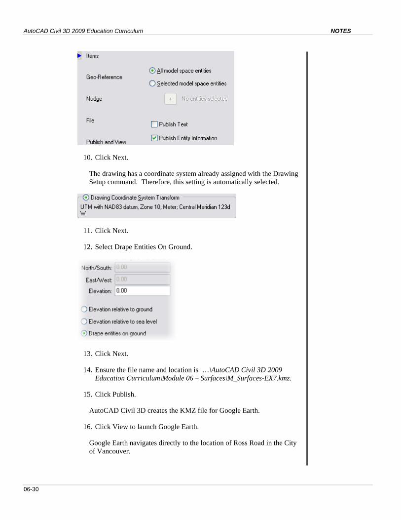
9. Select All Model Space Entities and Publish Entity Information.
AutoCAD Civil 3D 2009 Education Curriculum NOTES
06-30
10. Click Next.
The drawing has a coordinate system already assigned with the Drawing
Setup command. Therefore, this setting is automatically selected.
11. Click Next.
12. Select Drape Entities On Ground.
13. Click Next.
14. Ensure the file name and location is …\AutoCAD Civil 3D 2009
Education Curriculum\Module 06 – Surfaces\M_Surfaces-EX7.kmz.
15. Click Publish.
AutoCAD Civil 3D creates the KMZ file for Google Earth.
16. Click View to launch Google Earth.
Google Earth navigates directly to the location of Ross Road in the City
of Vancouver.
Module 06 - Surfaces NOTES
06-31
17. A new Place is added in the Places Window of Google Earth.
18. Use the navigation tools in Google Earth to examine the results.
19. Close the drawing and do not save the changes.
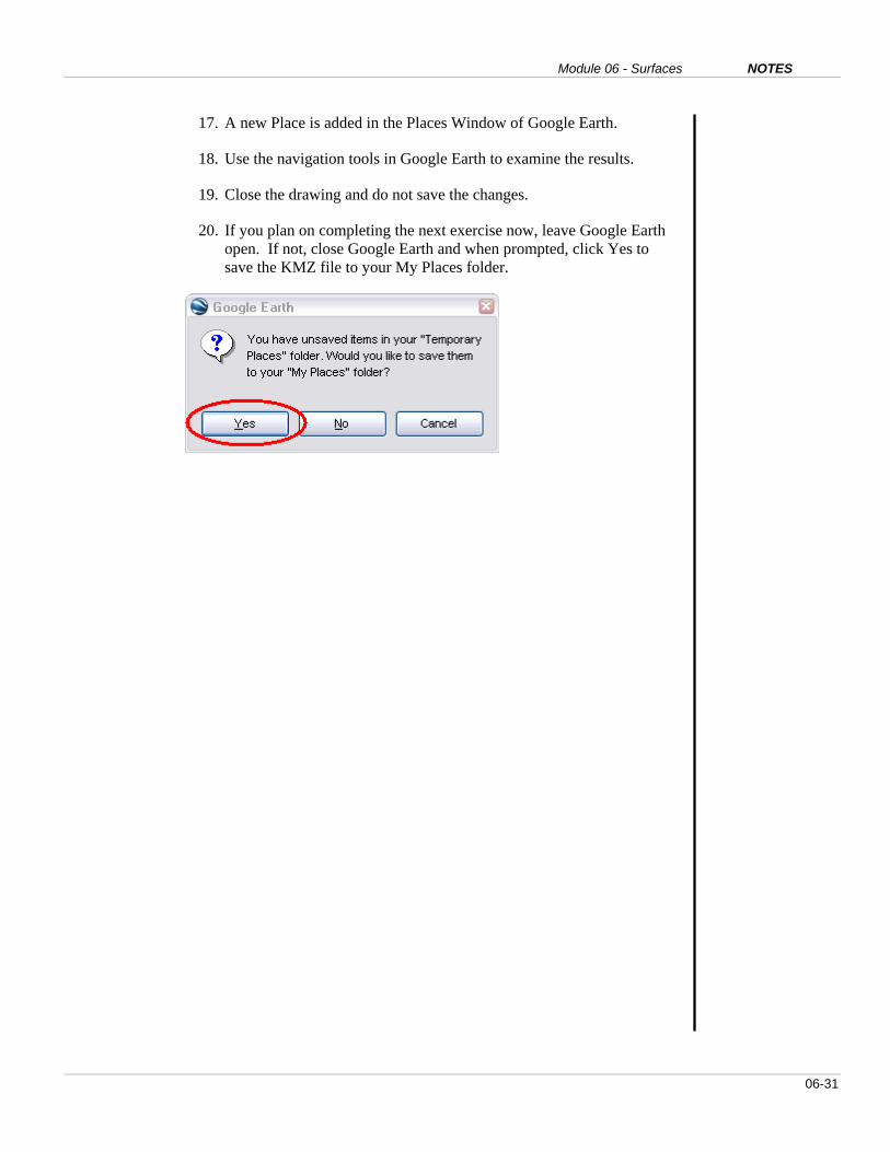
20. If you plan on completing the next exercise now, leave Google Earth
open. If not, close Google Earth and when prompted, click Yes to
save the KMZ file to your My Places folder.

AutoCAD Civil 3D 2009 Education Curriculum NOTES
06-32
EXERCISE 8: IMPORT AN IMAGE FROM GOOGLE EARTH
For this exercise, you must open the drawing provided.
In this exercise, you import an image from Google Earth to AutoCAD Civil
3D.
For this exercise, open …\Module 06 – Surfaces\M_Surfaces-EX8. This is a
metric drawing with a metric coordinate system assigned. The common
coordinate system enables the Civil 3D data to be exported to Google Earth.
Begin by re-establishing the view in Google Earth.
1. Launch Google Earth if you have not done so already.
2. In Google Earth Places, double-click M_Surfaces-EX7 Ross Road.
3. In Google Earth, adjust the zoom so you can see Ross Road.
4. In AutoCAD Civil 3D, click File > Import > Import Google Earth
Image.
5. Press ENTER to accept coordinate system.
6. The Google Earth image is displayed in AutoCAD Civil 3D.
7. Close the drawing and do not save the changes.

Module 06 - Surfaces NOTES
06-33
EXERCISE 9: DRAPE AN IMAGE ON A SURFACE
For this exercise, you must open the drawing provided.
In this exercise, you drape an image on a surface. Engineers often present
their plans to the public. A surface with a draped image is a very effective
means of communicating designs and proposed works to individuals who are
not used to viewing engineering drawings.
For this exercise, open …\Module 06 – Surfaces\M_Surfaces-EX9.
Insert the image.
1. Click Map > Image > Insert.
2. Browse to the …\AutoCAD Civil 3D 2009 Education
Curriculum\Module 06 – Surfaces\ folder.
3. Change the Files of Type to All Images. Click Vancouver.tif.
4. Click Open.
5. Click OK in the Image Correlation dialog box.
The image is inserted to the drawing.

AutoCAD Civil 3D 2009 Education Curriculum NOTES
06-34
6. Click the image border.
7. Right-click and click Display Order > Send to Back.
8. Click Surfaces > Utilities > Drape Image.
9. Change the Image to Vancouver_1.
10. Change the Surface to EG1.
11. In the Drape Image dialog box, click OK.
Civil 3D drapes the image.
Now isolate the surface.
12. Enter LAYISO (Layer Isolate). Press ENTER.
13. Click the surface and press ENTER.
Civil 3D turns all layers off except C_TOPO.

Module 06 - Surfaces NOTES
06-35
Now restore a saved 3D view.
14. Enter VPORTS (Viewports). Press ENTER.
15. Click the Named Viewports tab.
16. Select 3D and click OK.
17. Zoom close to the surface.
18. Enter RENDER. Press ENTER.
19. Click Continue.
Civil 3D launches the rendering application and renders the surface
using the inserted image.

AutoCAD Civil 3D 2009 Education Curriculum NOTES
06-36
Questions
1. What does the acronym TIN stand for?
2. Why would a surveyor exclude some points from a surface model?
Offer some examples of these types of points.
3. Explain why breaklines are necessary for surface modeling.
4. Why would an engineer modify the properties of a surface?
5. Explain when an engineer would use a no display, triangles, and
contours surface style.
6. What are the most common types of surface edits?
7. What is Google Earth and why is it useful?
8. Why would an engineer want to drape an image on a surface?
9. What is the Object Viewer used for?
Answers
1. TIN standards for Triangulated Irregular Network. Civil 3D uses a TIN
to represent surface models in AutoCAD Civil 3D.
2. A surveyor would exclude points from a surface model that do not
reflect the true topography. These points are referred to as Invalid DTM
points. Examples include sewer inverts, tops of fire hydrants, and sub-
surface valves.
3. Breaklines are used to represent distinct terrain breaks. Examples of
breaklines include road crowns, gutters, top of bank, bottom of bank,
stream edges, and creek edges. When creating surfaces it is important to
define breaklines to make sure the surface is accurate. Triangulation
lines are forced along breaklines.
4. Modifying surface properties enables you to change the style assigned to
the surface, specify the maximum triangle length to be used, allow for
crossing breaklines, and to review surface statistics.
5. A no display style is used to suppress the display of a surface. No
display styles make the drawing more manageable when working with
larger surfaces. A triangles style is useful for surface editing. A
contours surface style is used for presentation on final engineering
drawings.

Module 06 - Surfaces NOTES
06-37
6. The most common types of surface edits include deleting lines, adding
lines, and swapping edges.
7. Google Earth is a geospatial software application made available by
Google. Google Earth is useful because 1) you can export Civil 3D data
to Google Earth, and 2) you can import Google Earth images and surface
data to Civil 3D.
8. Draping an image on a surface is useful for the presentation of
engineering drawings to be viewed by the general public. This is an
effective means of communicating the details of a proposed civil
engineering project.
9. The Object Viewer is a useful tool for viewing Civil 3D data in a 3D
environment. The Object Viewer has a number of 3D navigation tools
and can also be used to render a surface model.
AutoCAD Civil 3D 2009 Education Curriculum NOTES
06-38
Module Summary
In this module you learned how to work with surfaces in AutoCAD Civil 3D.
You started by creating a few surface styles. The default surface style was set
and the surface naming template defined. After that the surface was created
using point group data and breaklines. The point group excludes invalid
DTM points and proximity breaklines were used. You then modified the
surface properties and edited the surface using the delete line, add line and
swap edges command. Once the surface was created, you annotated the
surface with contour labels, spot elevations and slope labels. The lesson
ended with exercises that addressed exchanging AutoCAD Civil 3D data with
Google Earth and vice Versa. Finally you draped an image on a surface and
viewed this using the Object Viewer.