Modular yielding support for tunnels in heavily swelling rock
7
Figure 1 : Effects of rock swelling in tunnelling [1] a) Bottom heave b) Swelling pressure on the invert with or without heave of the tunnel Preprint STUVA Conference `07 - 26.11. - 29. November 2007 Köln Rocks containing clay minerals and anhydrite exhibit the property of volume increase caused by water absorption. The phenomenon is called rock swelling. In tunnelling this swelling produces heave of the bottom of the tunnel or, if it is resisted, pressure is exerted on the invert (Figure 1). The latter is called swelling pressure. Experience shows that due to the swelling pressure, in many cases, stretches of the invert fail and the tunnel has to be repaired. With low overburden or yielding rock above the tunnel crown the tunnel tubes as a whole are pushed upwards and the ground surface itself may exhibit heave [1], [2]. The differences in heave along the axis of the tunnel that can be caused by this process lead, among other things, to the typical diagonal cracks in the tunnel lining, which can also necessitate repairs [3]. Generally low tolerances are specified, especially in the case of railway tunnels carrying high speed trains, so that in this case the criteria for serviceability are often more difficult to fulfil than those for structural safety. An investigation of tunnelling in earlier and more recent times shows that tunnels in swelling rock, especially in the regions of the Swiss Jura and southern Germany, in many areas exhibit gipskeuper formations containing anhydrite that are prone to cause damage. Over the years a number of tunnels have frequently had to be repaired in some sections. Examples from Switzerland are the railway tunnels Hauenstein and Ricken and the road tunnels Belchen and Seelisberg [4], and Wagenburg [3] in the region of Stuttgart in Germany. The repair work usually involves the demolition of an existing invert, removing material from the rock base, the construction of a new invert or even the replacement of the complete tunnel lining. This is very time-consuming and costly. Up till now, during such repair work this has generally resulted in an interference to tunnel operations or even a temporary closure of the tunnel. For example, the tunnel is closed in the night, or in the case of a twin track railway tunnel or of a road tunnel the traffic is restricted to one half of the tunnel or in the case of twin tube motorway tunnels only one tube is opened to traffic. The resulting more difficult working conditions lead to slower progress in the work, so that the reduced operational capacity may last for years. One such example is the abovementioned 8.1 km long Hauenstein base tunnel south of Basel. It was built in the period 1912 – 1916, the first repairs being carried out between 1919 and 1923. The recent repair work (1980 - 1986) took about 6 years to complete [5]. In recent times a change is perceptible regarding the readiness of users to accept longer operational restric- tions. The modern wide-area interconnected traffic infrastructures, due to the steadily increasing volume of traffic, demand a more unrestricted use of the tunnels. This is exemplified in the abovementioned 2.3 km long twin tube Belchen tunnel, part of the A2 motorway, built in the period 1963 - 1970, which passes through practi- cally the same formations (gipskeuper, opalinus clay) as the Hauenstein base tunnel [4], [5]. To be able to carry out extensive repair works in the tunnel and at the same time maintain tunnel operations, firstly a third tunnel tube is constructed. This is not a question of increasing Experience shows that even in recent times many tunnels located in heavily swelling rock, e.g. gipskeuper, have had to be reconstructed. This inevitably involves a temporary interference with or even a suspension of tunnel operations. Thus in the planning of important new traffic infrastructure projects efforts are being made to provide unlimited use of the structures for a working life of 50 to 100 years. In strongly swelling rock this goal can be achieved by using the new design concept called “Modular Yielding Support”, in which compressible elements of high bearing capacity are placed between the structure and the rock. On the one hand, this method permits a reduction of swelling pressure to a predetermined maximum value. On the other hand, replacement of these elements is possible at any time without impairing the flow of traffic. By providing direct access to the base of the tunnel, the region that is most endangered by swelling processes, an efficient control of ground water and a simple monitoring of ground behaviour is possible. The modular yielding support system has been successfully employed in the Chienberg road tunnel in Switzerland in the tunnel sections with gipskeuper at the base of the tunnel, with soil covering the crown of the tunnel as well as a small depth of overburden. Modular yielding support for tunnels in heavily swelling rock Prof. Dr. Kalman Kovári, consulting engineer Dipl. Ing. Flavio Chiaverio, Aegerter & Bosshardt AG INTRODUCTION 1. Summary a) b) u u S u F p
Transcript of Modular yielding support for tunnels in heavily swelling rock

Figure 1 : Effects of rock swelling in tunnelling [1]a) Bottom heaveb) Swelling pressure on the invert with or without heave of the tunnel
Preprint STUVA Conference `07 - 26.11. - 29. November 2007 Köln
Rocks containing clay minerals and anhydrite exhibit the property of volume increase caused by water absorption. The phenomenon is called rock swelling. In tunnelling this swelling produces heave of the bottom of the tunnel or, if it is resisted, pressure is exerted on the invert (Figure 1). The latter is called swelling pressure. Experience shows that due to the swelling pressure, in many cases, stretches of the invert fail and the tunnel has to be repaired. With low overburden or yielding rock above the tunnel crown the tunnel tubes as a whole are pushed upwards and the ground surface itself may exhibit heave [1], [2]. The differences in heave along the axis of the tunnel that can be caused by this process lead, among other things, to the typical diagonal cracks in the tunnel lining, which can also necessitate repairs [3]. Generally low tolerances are specified, especially in the case of railway tunnels carrying high speed trains, so that in this case the criteria for serviceability are often more difficult to fulfil than those for structural safety.
An investigation of tunnelling in earlier and more recent times shows that tunnels in swelling rock, especially in the regions of the Swiss Jura and southern Germany, in many areas exhibit gipskeuper formations containing anhydrite that are prone to cause damage. Over the
years a number of tunnels have frequently had to be repaired in some sections. Examples from Switzerland are the railway tunnels Hauenstein and Ricken and the road tunnels Belchen and Seelisberg [4], and Wagenburg [3] in the region of Stuttgart in Germany.
The repair work usually involves the demolition of an existing invert, removing material from the rock base, the construction of a new invert or even the replacement of the complete tunnel lining. This is very time-consuming and costly. Up till now, during such repair work this has generally resulted in an interference to tunnel operations or even a temporary closure of the tunnel. For example, the tunnel is closed in the night, or in the case of a twin track railway tunnel or of a road tunnel the traffic is restricted to one half of the tunnel or in the case of twin tube motorway tunnels only one tube is opened to traffic. The resulting more difficult working conditions lead to slower progress in the work, so that the reduced operational capacity may last for years. One such example is the abovementioned 8.1 km long Hauenstein base tunnel south of Basel. It was built in the period 1912 – 1916, the first repairs being carried out between 1919 and 1923. The recent repair work (1980 - 1986) took about 6 years to complete [5].
In recent times a change is perceptible regarding the readiness of users to accept longer operational restric-tions. The modern wide-area interconnected traffic infrastructures, due to the steadily increasing volume of traffic, demand a more unrestricted use of the tunnels. This is exemplified in the abovementioned 2.3 km long twin tube Belchen tunnel, part of the A2 motorway, built in the period 1963 - 1970, which passes through practi-cally the same formations (gipskeuper, opalinus clay) as the Hauenstein base tunnel [4], [5]. To be able to carry out extensive repair works in the tunnel and at the same time maintain tunnel operations, firstly a third tunnel tube is constructed. This is not a question of increasing
Experience shows that even in recent times many tunnels located in heavily swelling rock, e.g. gipskeuper, have had to be reconstructed. This inevitably involves a temporary interference with or even a suspension of tunnel operations. Thus in the planning of important new traffic infrastructure projects efforts are being made to provide unlimited use of the structures for a working life of 50 to 100 years. In strongly swelling rock this goal can be achieved by using the new design concept called “Modular Yielding Support”, in which compressible elements of high bearing capacity are placed between the structure and the rock. On the one hand, this method permits a reduction of swelling pressure to a predetermined maximum value. On the other hand, replacement of these elements is possible at any time without impairing the flow of traffic. By providing direct access to the base of the tunnel, the region that is most endangered by swelling processes, an efficient control of ground water and a simple monitoring of ground behaviour is possible. The modular yielding support system has been successfully employed in the Chienberg road tunnel in Switzerland in the tunnel sections with gipskeuper at the base of the tunnel, with soil covering the crown of the tunnel as well as a small depth of overburden.
Modular yielding support for tunnels in heavily swelling rock
Prof. Dr. Kalman Kovári, consulting engineer Dipl. Ing. Flavio Chiaverio, Aegerter & Bosshardt AG
INTRODUCTION1.
Summary
a) b)
u
uS
uF
p

Figure 2: Yielding principle a) Surficial Yielding Support b) Modular Yielding Support
2Preprint STUVA Conference `07 - 26.11. - 29. November 2007 Köln
That these swelling processes only occur in rocks containing clay minerals or anhydrite and that the presence of surplus water is a basic condition for the process to take place was known already when the railways came into being in the middle of the 19th century. However, that swelling was influenced by the stress redistribution due to the excavation of the tunnel was only realized much later, thanks to the work of Terzaghi [7].
Swelling in clay is determined by the inner crystalline osmotic adsorption of water molecules in the plate-like structure of clay minerals like illite, corensite or montmorillonite. From oedometer tests it is shown that the relationship between swelling pressure σ and heave ε due to swelling can be described by the so called swelling law, in which ε decreases linearly with log σ [7], [8]. The swelling potential of a rock is characterized by the unhindered amount of swelling ε0 [%] and the maximum swelling pressure σ0 (with total prevention of swelling). The pair of values, ε0 and σ0, describe the swelling potential of a rock sample or of a rock type. In general, in the case of rocks containing clay minerals,
Rock is usually inhomogeneous, so that the content of swelling minerals and thus the swelling potential can vary greatly within a small distance. This is valid both within the profile and along the tunnel axis. The results of swelling tests on samples taken from the same borehole usually exhibit a strong variation.Due to fissures, joints, stratification and frequently
•
•
based on systematic laboratory tests a higher value of ε0 is associated with a higher value of σ0 [9]. It is well known that swelling in anhydrite is of a chemical nature and depends on the transformation of anhydrite into gypsum. Here, under controlled laboratory conditions, a volume increase of 61 % is theoreti-cally possible. If, in the laboratory, the swelling strain is completely prevented for small samples, maximum swelling pressures of σ0 of up to 8 MPa are determined, whereby the final state of the slowly occurring process was not reached in tests [10]. For rocks containing anhydrite, due to the purely chemical nature of the processes the validity of the semi-logarithmic swelling law cannot be verified either empirically or on the basis of theoretical considerations. One can only show that with increasing swelling pressure σ the rate of devel-opment of the swelling strain ε is greatly reduced. It is assumed, at least in the laboratory (closed system), that over longer periods of time, allowing swelling strain is not necessarily connected with a reduction of the maximum swelling pressure or its final value [11]. The large-scale tests carried out in the test gallery of the Freudenstein tunnel in 5 testing areas with different lining stiffnesses (0, 0.1, 0.25, 0.5 and 0.75 MPa) have shown that the rate of heave of the bottom of the tunnel is substantially reduced with increasing stiffness of the lining [4], [11]. On the other hand, it must be said that also in anhydrite the development of swelling pressure over time decreases rapidly when only a small heave is allowed.
If we now consider possible swelling processes that can occur in the vicinity of a tunnel, the following factors deserve special attention:
the tunnel’s capacity, but simply of maintaining the full potential of the existing structure. From these considerations it is clear that in future for important tunnels located in strongly swelling rock formations the serviceability should be as unrestricted as possible. This can be achieved by means of the design concept called “Modular Yielding Support” developed by K. Kovári. The aim is threefold. Firstly, the swelling pressure acting on the structure should be limited to a prescribed value. Secondly, it must always be possible, without interference to tunnel operations, to carry out repair work below the traffic space. Thirdly, an effective ground water control must be ensured. The concept was applied for the first time in the Chienberg tunnel, as reported in the following [6].
encountered dislocation of the bedding joints the permeability of the rock is liable to strong variations locally. Consider, for example, actual faults and non-swelling but strongly jointed in-termediate rock strata exhibiting particularly high permeability. In rock, water is present in the form of pore water and joint wa-ter. The water storage capacity of rock is generally very vari-able within larger rock masses. Excavating a cavity causes stress redistribution in its imme-diate neighbourhood, which can increase the rock permeability locally.Due to tunnel excavation it is unavoidable that a hydraulic gradient along the tunnel axis is produced.
•
•
•
THE SWELLING PROCESS IN THE ROCK SURROUNDING A TUNNEL2.
KnautschzoneYielding zone
KnautschelementYielding element
FelsankerRock anchor
a) b)
5m

Figure 3: Force - Displacement Diagram of a yielding element
3Preprint STUVA Conference `07 - 26.11. - 29. November 2007 Köln
Furthermore, based on observations and measurements the following points apply:
Swelling processes in a rock mass in an amount of practical significance occur only at the bottom of a cavity. Up till now only one exception to this rule was observed using instruments, i.e. in the Chienberg tunnel (in gipskeuper) [6], where laterally to the pro-file swelling expansion also occurs at the level of the invert of the tunnel tube. The swelling strain decreases with distance from the cavity and is insignificant at a depth corresponding to roughly the diameter of the cavity [1], [2].Swelling processes can take place very quickly or with considerable delay, their intensity can vary strongly and they can persist for many years [4].
•
•
•
It may be concluded that when tunnelling in swelling rock, even if in some sections of the rock dry condi-tions are predicted, with the long working life one must reckon with the occurrence of swelling processes. Thus even with an extremely efficient water control during construction this calls for an expert design of the structure.
Based on geological investigations, swelling tests performed in the laboratory and experience with other structures it is assumed that for the rock glo-bally valid reference values of the amount of swelling ε0 and of swelling pressure σ0 and for rocks contain-ing both clay minerals and anhydrite the semi-loga-rithmic swelling law may be applied [1], [2], [11]. For example, in the case of the 5.3 km long Adler tunnel of the Swiss Federal Railways opened in the year 2000 with an excavated diameter of the TBM of ø = 12.5 m, the statical analysis of the tunnel (for struc-tural safety) was based on a maximum swelling pres-sure of 4 MPa [13]. With the Engelberg base tunnel of the three-way motorway interchange Leonberg in Germany the “magnitude of the assumed swelling pressure varied between 2 MPa and 6 MPa depend-ing on the amount of overburden” [14]. A construction method is chosen and the dimension-ing is carried out based on the assumptions made above and by applying suitable analysis methods. Here the rock’s swelling characteristic line is very useful for determining the pressure acting on the invert [1], [2]. Based on a risk analysis the acceptable remaining risk is estimated for a possible exceedance of the maximum swelling pressure or the admissible heave. In the case of assumed residual risks, besides economic criteria the maximum possible unrestricted use of the structure plays an important role. New knowledge concerning expected rock behaviour gained during construction could influence the above decisions. For this reason alone it is very important to carry out deformation measurements during the execution phase.
•
•
•
•
From the above brief summary of the state of our empirical and theoretical knowledge it is clear that in the planning phase the predictability of swelling processes for a working life of around 100 years is rather limited, especially in rock containing anhydrite [11]. As mentioned above, the main reasons lie in our inadequate knowledge of the distribution of the swelling potential of in situ rock and the supply of water to the materials exhibiting swelling capacity. In gipskeuper there is also some uncertainty about the relationship between swelling pressure and swelling-induced heave.
We may ask, how then in practice, in view of the basic uncertainties discussed above, do engineers tackle the problem of the design and construction of tunnels in swelling rock?
In order to counteract the unfavourable effects of swelling rock, in practice one has always adopted two quite different construction principles [1] [2]. On the one hand, we have the so called resistance principle, whereby the heave of the bottom of the tunnel is prevented by means of an invert and the swelling pressure that thereby develops is resisted without any structural damage. On the other hand, we have the so called yielding principle, in which a yielding zone is placed between the invert and the rock and a limited heave of the bottom of the tunnel is allowed in order to reduce the maximum value of the swelling pressure. The resistance principle is the more popular solution for small to medium swelling potential, but for high swelling pressures its becomes uneconomic. With a small overburden or with yielding zones in the region of the crown of the tunnel, use of the principle is risky, since in such cases one has to reckon with a heave of the tunnel tube as a whole, which can impair both serviceability and structural safety. With the yielding principle, a compressible medium is inserted at the base of the tunnel between the rock and the lining, with the aim of reducing the maximum swelling pressure by permitting heave of the base of the tunnel. In the case of Tunnel T8 of the national
The following steps may be distinguished:
On the excavated surface of the tunnel the pore and joint water pressures fall to the atmospheric value, so that seepage radial to the cavity occurs.
•
DESIGN AND CONSTRUCTION 3.
Kra
ft F
Forc
e F
Verschiebung δDisplacement δ
VerfestigungStrain hardening
δ
F

Figure 4: Yielding element with the principle of penetration (rock anchors in the bottom)
4Preprint STUVA Conference `07 - 26.11. - 29. November 2007 Köln
As signified by the terminology, the yielding zone is formed of individual elements and the profile is designed such that the elements are accessible at any time during the service life of the tunnel and thus if necessary can be replaced without interfering with tunnel operations. The concept is illustrated schematically in the case of the Freudenstein tunnel [1], [2], [9]. Figure 2a shows the Surficial Yielding Support applied there and Figure 2b shows a possible design according to the Modular Yielding Support. Instead of lateral concrete haunches, yielding elements of cylindrical form are installed and spaced closely along the tunnel axis. They serve as the foundation of the whole structure and resist the rock pressure acting on the roof, the self-weight of the structure and the live load. Their “yielding force”, i.e. the force at which the elements yield in compression, must correspond to a chosen safety factor greater than the sum of the above loads. The level of the foundation depends on the statically required thickness of the concrete structure in the middle of the tunnel and the
highway A16 in the Swiss Jura a yielding zone was employed with yielding support ribs of quadratic cross section (0.3 x 0.3 m) spaced at 2.0 m intervals [15]. In the case of the Freudenstein tunnel of the German Federal Railways in the neighbourhood of Karlsruhe, Germany, the “Surficial Yielding Support“ consisting of a fill-placement of expanded highly porous clay of thickness 1.2 m was employed [1], [2], [9]. In the case of the Engelberg base tunnel each tube with three lanes and an excavated diameter of 21 m, the thickness of the yielding zone consisting of such expanded clay was 1.7 m [14].
Thus with these structures it is assumed that the compressibility of the inserted yielding zone is not exhausted before the end of the planned working life and thereby an inadmissibly large swelling pressure cannot act on the base of the tunnel. In order to exclude the risk of a setback of this kind and of inadmissible tunnel heave, the “Modular Yielding Support” was devised.
chosen height of the free space left underneath for the maintenance of the invert. The swelling-induced heave of the flat invert between the foundation elements is constrained by a series of highly prestressed anchors. To avoid the anchors losing their bearing capacity after only a short time due to swelling-induced heave, the anchor heads are designed in such a way that the anchor force remains practically constant for a certain amount of base heave. It is known from experience that swelling along a tunnel axis, despite having the same geological conditions, can exhibit quite different values. This fact is not only due to a different distribution of swelling potential, but mainly to the local conditions of water supply from the rock to the regions of swelling rock. Precisely because of this the Modular Yielding Support is very advantageous, because the swelling process can be easily and directly observed and inter-vention is also possible at selective points.
In the case of the tunnel discussed in Figure 2b the foundations had typically a diameter of øF = 1.0 – 1.5 m and the anchor heads a diameter of øA = 0.6 – 1.0 m. The height of the yielding elements corresponds approximately to their diameter. The load capacity in the yielding process is FF = 5 – 10 MN for the foundation elements and FA = 1.0 – 1.5 MN for the anchor head. The elements only have to be replaced after being compressed to 0.4 - 0.5 m. At the same time the uplifted tunnel base has to be corrected by the same amount. It is also possible, of course, to collect any ground water that has seeped into the region of the tunnel base and drain it away. In this way the development of swelling can be substantially delayed or even eliminated.
It is evident that in the case of the Freudenstein tunnel the Modular Yielding Support would require roughly the same area of excavated cross section as the Surficial Yielding Support that was installed. Paul and Wichter [3] for a similar tunnel profile to that shown in Figure 2b have proposed a planned free space for a completely unrestrained base heave with “tunnel tubes completely fixed in the rock”.
With these elements, under axial loading force-displacement diagrams as shown in Figure 3 can be obtained. It is desirable to have as large a displacement as possible under a high constant force, before the process leads to an increasing hardening effect. A loss of bearing capacity is excluded with these elements. To satisfy the required durability requirement they consist of inert materials like cement, sand, porous glass foam and steel in the form steel fibres and reinforcement. The details of the construction of these special structural elements (shape, dimensions, matrix, reinforcement
THE MODULAR YIELDING SUPPORT 4.
Yielding Elements
AnkerstabRod
KnautschkörperYielding body
LastplattePlate

Figure 5: Chienbergtunnel - Reconstruction using the Modular Yielding Support
5Preprint STUVA Conference `07 - 26.11. - 29. November 2007 Köln
This tunnel forms part of the main road H2 from Liestal to Sissach and is about 25 km south east of Basel. Among other things it crosses the typical Jura formations of gipskeuper with sulphates in the form of anhydrite and gypsum together with weathered marl. The length of the conventionally (i.e. with mining technique) excavated stretch of tunnel is 1.5 km. Because of the expected high swelling pressures in gipskeuper a practically circular profile was chosen with a concrete thickness of the inner lining between 0.7 m and 1.1 m. For stretches with low depth of overburden and swelling rock beneath the tunnel base a variant design with the Surficial Yielding Support – similar to that used in the Freudenstein tunnel – was initially also taken into consideration. But due to an inadequate (as it turned out later) estimate of the long-term swelling behaviour of the rock the variant design was dispensed with. The tunnel was constructed using the Sprayed Concrete Lining Method applying a top headingpro-cedure. Due to the expected swelling behaviour at the base of the tunnel the ring closure of the inner lining was carried out such that it followed the excavation of the top heading at the latest within 25 weeks or within a maximum distance of 450 m. In the first stretch of tunnel (about 90 m long) with an overburden of about 25 - 30 m, with gipskeuper in the region of the base and weathered marl above the tunnel crown, already 4 months after the ring closure of the inner lining heave
layout, etc.) depend on the specific practical require-ments that have to be fulfilled from case to case. However, all element types whether of cylindrical, cubic or prismatic shape, undergo the same micro-mechanical process during loading, i.e. progressive closure of the pores under conditions of constrained lateral deformation. The first yielding elements of this type were developed for tunnelling in squeezing rock. The beam-like yielding elements, which are placed in the sprayed concrete lining in several places around the profile, give it a high bearing capacity, while at the same time allowing rock deformations (convergence). The foundation and anchor elements, that form part of the Modular Yielding Support, were designed later to be cylindrical in shape but the force is introduced differ-ently.
The foundation element is placed between a concrete foundation and the actual tunnel structure. Due to swelling at the base of the tunnel the element is subjected to an increase in load and after reaching the yield force it begins to yield. We are dealing here with axial loading, but this can also be conceived as a constrained deformation. Theoretically, the element exhibits a homogeneous stress state corresponding to the “yield stress”.
The corresponding yielding element for the anchor heads is based on the principle of penetrating the anchor plate with a smaller diameter than that of the yielding element (Figure 4). This system also functions perfectly well if there is some eccentricity of the force transmission (anchor force).
both of the tunnel crown and at the built-up ground surface was observed with control measurements. In the second stretch (about 140 m long) with a depth of overburden of about 40 - 50 m the same phenomenon with a similar time dependence was observed. After approximately one year the maximum heave in the first stretch of tunnel crown was 83 mm and in the second one about 30 mm. At the ground surface a hump-shaped heave extending of up to 50 m developed at right angles to the tunnel axis. At this point in time the rate of heave of the tunnel crown has reached a maximum value of about 4.5 mm/month.
From deformation measurements in the ground it was observed that large zones of rock, not only under the base but also laterally to the tunnel profile, were affected by swelling, so that the completion of the tunnel was called into question.
In this situation, after considering numerous variants, the Modular Yielding Support, with the possibilities of the newly developed yielding element was applied. It was a question of reconstructing the existing tunnel in two sections of total length 430 m even before it was opened. The details of the novel excavation system and its implementation, as well as the initial experience gained since the opening of the tunnel in December 2006 have been published elsewhere [6]. In the following we only want to deal with the most important steps in the reconstruction of the tunnel (Figure 5). After demolishing the bottom half of the inner lining and extending the profile to form a horseshoe shape with a flat base, there followed the new concrete construction with the sidewalls and carriageway slab. The expected, more or less intensive heave due to swelling at the base of the tunnel is slowed down by means of a series of prestressed anchors. The structure itself is founded on the sidewalls resting on the yielding elements directly on the rock. In total 570 such foundation elements
APPLICATION IN THE CHIENBERG TUNNEL 5.
Bestehendes InnengewölbeExisting lining
NeukonstruktionNew construction
KnautschelementYielding element
FelsankerRock anchor
UrsprünglichesGewölbeInitial lining
5m
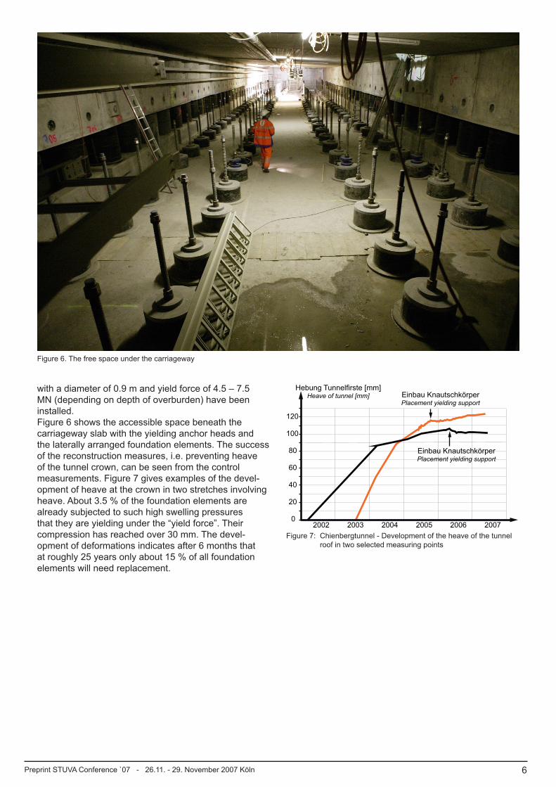
Figure 6. The free space under the carriageway
Figure 7: Chienbergtunnel - Development of the heave of the tunnel roof in two selected measuring points
6Preprint STUVA Conference `07 - 26.11. - 29. November 2007 Köln
with a diameter of 0.9 m and yield force of 4.5 – 7.5 MN (depending on depth of overburden) have been installed.Figure 6 shows the accessible space beneath the carriageway slab with the yielding anchor heads and the laterally arranged foundation elements. The success of the reconstruction measures, i.e. preventing heave of the tunnel crown, can be seen from the control measurements. Figure 7 gives examples of the devel-opment of heave at the crown in two stretches involving heave. About 3.5 % of the foundation elements are already subjected to such high swelling pressures that they are yielding under the “yield force”. Their compression has reached over 30 mm. The devel-opment of deformations indicates after 6 months that at roughly 25 years only about 15 % of all foundation elements will need replacement.
0
40
60
80
100
120
2002 2004 2005 2006 2007
20
2003
Hebung Tunnelfirste [mm]Heave of tunnel [mm] Einbau Knautschkörper
Placement yielding support
Einbau KnautschkörperPlacement yielding support

7Preprint STUVA Conference `07 - 26.11. - 29. November 2007 Köln
[1] Kovári, Kalman; Amstad, Christian; Anagnostou, Georg: Design/Construction methods - Tunneling in swelling rocks, Key Questions in Rock Mechanics, Cundall et all (eds), proceedings of the 29th U.S. Symposium University of Minnesota/Minneapolis, 13-15 June 1988, Balkema
[2] Kovári, Kalman; Amstad, Christian; Anagnostou, Georg: Tunnelbau in quellfähigem Gebirge, Mittei-lungen der Schweizerischen Gesellschaft für Boden- und Felsmechanik, No.115, Mai 1987
[3] Paul, Axel; Wichter, Lutz: Das Langzeitverhalten von Tunnelbauwerken im quellenden Gebirge – Neuere Messergebnisse vom Stuttgarter Wagen-burgtunnel, Taschenbuch für den Tunnelbau, Verlag Glückauf, Essen, 1996
[4] Amstad, Christian; Kovári, Kalman: Untertagbau in quellfähigem Fels, Forschungsbericht 52/94, Bundesamt für Strassen (ASTRA) Bern, März 2001
[5] Kovári, Kalman; Descoeudres, Francois: Tunnelling Switzerland, Swiss Tunnelling Society, 2nd edition 2002
[6] Hofer, Ruedi; Chiaverio, Flavio; Kovári, Kalman: Chienbergtunnel Sissach Tunnelhebung infolge Quellen, Swiss Tunnel Congress 2007 Luzern, Tagungsband, FGU Fachgruppe Untertagbau Juni 2007
[7] Terzaghi, Karl: Rock Defects and Loads on Tunnel Supports, Rock Tunnelling with Steel Supports, R. V. Proctor and Th. White, Commercial Shearing and Stamping Company, Youngstown, Ohio, USA, 1946
[8] Huder, Jachen; Amberg, Georg: Quellung im Mergel, Opalinuston und Anhydrit, Schweizerische Bauzeitung, 43, 1970
[9] Madsen, Franz, Müller Vonmoos, Markus: Das Quellverhalten der Tone, Tonmineralogie und Bodenmechanik, Mitteil. des Inst. für Grundbau und Bodenmechnik, ETH Zürich, Nr. 133, 1988
[10] Kirschke, Dieter; Kovári, Kalman; Prommersberger, Gerhard: Bemessungsgrundlagen und Konstruktion der Sohle des Freudensteintunnels, Ingenieurbau-werke, DB Neubaustrecke Mannheim-Stuttgart, Nr. 7, (1991)
[11] Anagnostou, Georg: Zur Problematik des Tunnelbaus in quellfähigem Gebirge, Mitteilungen der Schweiz. Ges. für Boden- und Felsmechanik, Band 154, 2007
[12] Wittke, Walter; Wittke, Martin; Wahlen, Roman: Zum Quellgesetz für den anhydritführenden, unaus-gelaugten Gipskeuper; Geotechnik 27, Nr. 2, 2004
[13] Chiaverio, Flavio; Hürzeler, Daniel: Der Adlertunnel, Schweizerische Bauzeitung, sia Nr. 18, 1996
[14] André, Peter: Engelberg-Basistunnel und Autobahn-dreieck Leonberg; Landesamt für Strassenwesen BadenWürttenberg, 1999
[15] Kovári, Kalman; Madsen, Franz; Amstad Christian: Tunnelling with Yielding Support in Swelling Rocks, Proc. Int.Symp. on Weak Rock, Tokyo, 1981
LITERATURE6.