Modular Receiver/Multicoupler System - Full Compass Wideband Receiver Modular Receiver/Multicoupler...
32
Venue Wideband Receiver Modular Receiver/Multicoupler System INSTALLATION GUIDE Rio Rancho, NM, USA www.lectrosonics.com Fill in for your records: Serial Number: Purchase Date: Hardware/Software Installation and Configuration Includes three models: • Wideband (blocks 21 through 29) • Wideband Low (blocks 470 through 26) • Wideband High (blocks 25 through 33)
Transcript of Modular Receiver/Multicoupler System - Full Compass Wideband Receiver Modular Receiver/Multicoupler...
Venue Wideband ReceiverModular Receiver/Multicoupler System
INSTALLATION GUIDE
Rio Rancho, NM, USAwww.lectrosonics.com
Fill in for your records:
Serial Number:
Purchase Date:
Hardware/Software Installation and Configuration
Includes three models:• Wideband (blocks 21 through 29)• Wideband Low (blocks 470 through 26)• Wideband High (blocks 25 through 33)

Venue Wideband Receiver
LECTROSONICS, INC.2
Digital Hybrid Wireless™ Modular Receiver System
Rio Rancho, NM, USA 3
IntroductionThe Venue Wideband receiver is a modular rack mount design for use with a wide variety of transmitters from Lectrosonics and other manufacturers. Designed for maximum versatility and performance, the wideband design offers the flexibility needed in today’s changing and increasingly congested RF environments.
A Venue receiver is a “system” that consists of a master unit and up to six receiver modules. Two different types of receiver modules are available. The standard module (VRS) is an excellent choice for fixed installations where fairly clear RF spectrum is available. The tracking mod-ule (VRT) is a more costly alternative, but its tracking front-end makes it the better choice for use in congest-ed RF environments. VRpanel software is included to simplify setup and monitoring.
This guide covers the essential steps and settings needed to get a Venue system up and running. It covers the hardware installation, configuration using the LCD on the master unit, setting up a USB port on the com-puter and installing the VRpanel software.
LecNet2 software runs under Microsoft Windows® XP, VistaTM and Windows 7 operating systems.* An online Help in the software includes a listing of commands used to control the Venue through the serial ports.
* Windows is a registered trademark of Microsoft Corp.
Vista is a trademark of Microsoft Corp.
NOTE: This equipment has been tested and found to comply with the limits for a Class B digital device, pursuant to Part 15 of the FCC Rules. These limits are designed to provide reasonable protection against harmful interference in a residential installation. The equip-ment generates, uses and can radiate radio frequency energy and, if not installed and used in accordance with the instructions, may cause harmful interference to radio com-munications. However, there is no guarantee that interference will not occur in a particular installation. If this equipment does cause harmful interference to radio or television recep-tion, which can be determined by turning the equipment off and on, the user is encour-aged to try to correct the interference by one or more of the following measures:
• Reorientorrelocatethereceivingantenna
• Increasetheseparationbetweentheequipmentandreceiver
• Connecttheequipmentintoanoutletonacircuitdifferentfromthatwhichthereceiv-er is connected
• Consultthedealeroranexperiencedradio/TVtechnicianforhelp
Changes or modifications to this equipment not expressly approved by Lectrosonics, Inc. could void the user’s authority to operate it.

Venue Wideband Receiver
LECTROSONICS, INC.4
Digital Hybrid Wireless™ Modular Receiver System
Rio Rancho, NM, USA 5
Table of ContentsIntroduction ............................................................................ 3Venue System Controls and Functions ............................... 6
Front Panel ........................................................................... 6Rear Panel ........................................................................... 7
Hardware Installation ............................................................ 8Receiver Modules ................................................................ 8Rack Installation ................................................................... 8Audio Outputs ...................................................................... 8RS-232 Port Pinouts ............................................................ 9Connections for Computer Interface .................................... 9
Initial Startup ....................................................................... 10Navigating the LCD Menus and Screens ........................... 11Resetting to Factory Defaults ............................................. 12System Setup with the LCD ................................................ 12
Selecting Compatibility Modes ........................................... 12Selecting the Noise Reduction Mode ................................. 12Selecting Diversity Modes .................................................. 13Selecting the Tuning Mode ................................................. 14Finding Clear Frequencies with SmartTune ....................... 14Finding Clear ChannelsUsing Full Spectrum Scan ............ 15Adjusting Audio Output Levels ........................................... 16Selecting Audio Phase ....................................................... 16Selecting Transmitter Battery Status Monitoring Mode ...... 17Locking Out the Front Panel Controls ................................ 18
Installing LecNet2™ Software and USB Driver .................. 19Firmware Update Instructions ............................................ 21Setting Up the Venue Receiver Using VRpanel ................. 22
Opening VRpanel with USB Port ....................................... 22Opening VRpanel with a COM Port ................................... 22VRpanel Main Window ....................................................... 22Main Window Top Menu Items ........................................... 23Popup Menu Items ............................................................. 23
Antenna Use and Placement .............................................. 25Powering Remote RF Amplifiers ........................................ 25
Pre-coordinated Frequencies ............................................. 26Compatible Frequency Table .............................................. 26Compatibility Diagram ........................................................ 27
Diagnostics .......................................................................... 28Multi-channel System Checkout......................................... 28Pilot Tone Bypass ............................................................... 28
Accessories and Common Replacement Parts ................ 29Remote Antennas .............................................................. 29Coaxial Cable ..................................................................... 29Coaxial RF Amplifier .......................................................... 29Common Replacement Parts ............................................. 29
Service and Repair .............................................................. 30Returning Units for Repair ................................................. 30
Venue Wideband Receiver
LECTROSONICS, INC.6
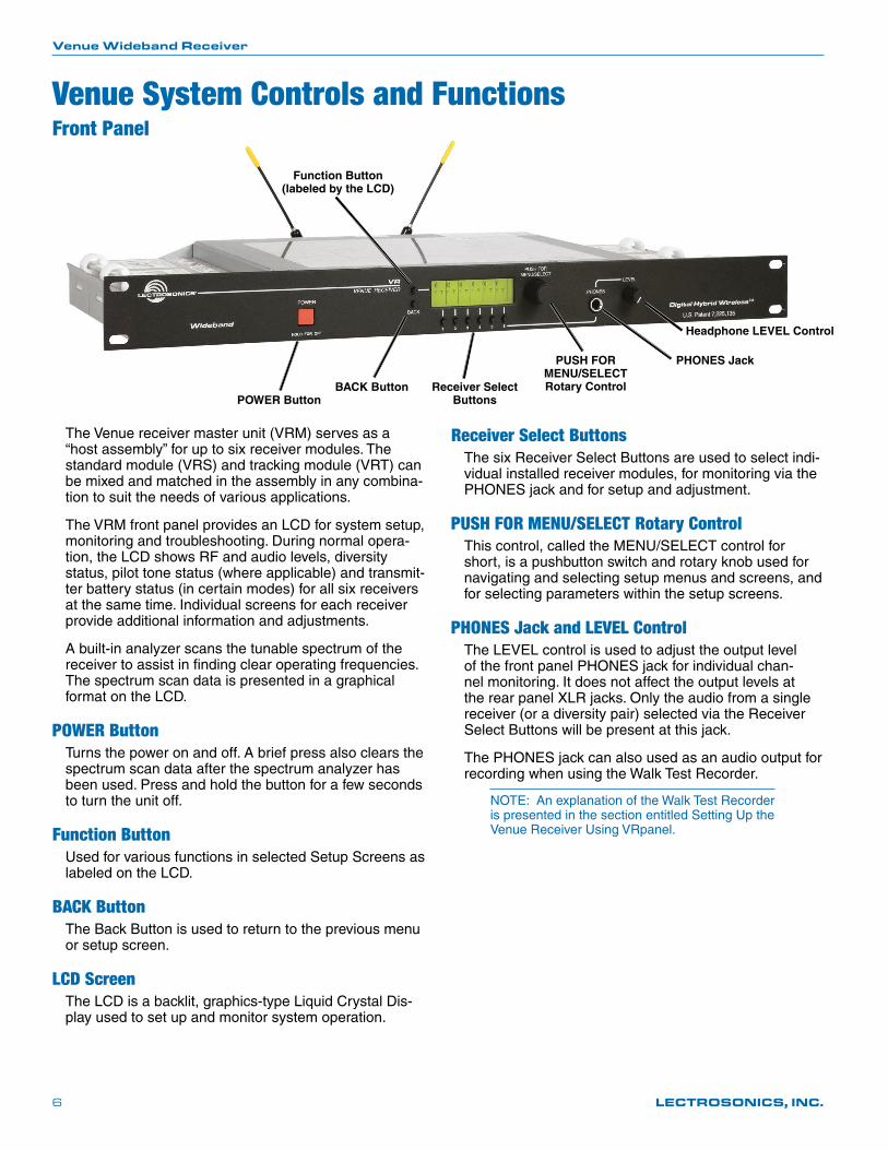
POWER Button
Headphone LEVEL Control
PHONES Jack
Receiver Select Buttons
Function Button (labeled by the LCD)
BACK Button
PUSH FOR MENU/SELECT Rotary Control
The Venue receiver master unit (VRM) serves as a “host assembly” for up to six receiver modules. The standard module (VRS) and tracking module (VRT) can be mixed and matched in the assembly in any combina-tion to suit the needs of various applications.
The VRM front panel provides an LCD for system setup, monitoring and troubleshooting. During normal opera-tion, the LCD shows RF and audio levels, diversity status, pilot tone status (where applicable) and transmit-ter battery status (in certain modes) for all six receivers at the same time. Individual screens for each receiver provide additional information and adjustments.
A built-in analyzer scans the tunable spectrum of the receiver to assist in finding clear operating frequencies. The spectrum scan data is presented in a graphical format on the LCD.
POWER ButtonTurns the power on and off. A brief press also clears the spectrum scan data after the spectrum analyzer has been used. Press and hold the button for a few seconds to turn the unit off.
Function ButtonUsed for various functions in selected Setup Screens as labeled on the LCD.
BACK ButtonThe Back Button is used to return to the previous menu or setup screen.
LCD ScreenThe LCD is a backlit, graphics-type Liquid Crystal Dis-play used to set up and monitor system operation.
Venue System Controls and Functions
Receiver Select ButtonsThe six Receiver Select Buttons are used to select indi-vidual installed receiver modules, for monitoring via the PHONES jack and for setup and adjustment.
PUSH FOR MENU/SELECT Rotary ControlThiscontrol,calledtheMENU/SELECTcontrolforshort, is a pushbutton switch and rotary knob used for navigating and selecting setup menus and screens, and for selecting parameters within the setup screens.
PHONES Jack and LEVEL ControlThe LEVEL control is used to adjust the output level of the front panel PHONES jack for individual chan-nel monitoring. It does not affect the output levels at the rear panel XLR jacks. Only the audio from a single receiver (or a diversity pair) selected via the Receiver Select Buttons will be present at this jack.
The PHONES jack can also used as an audio output for recording when using the Walk Test Recorder.
NOTE: An explanation of the Walk Test Recorder is presented in the section entitled Setting Up the Venue Receiver Using VRpanel.
Front Panel
Digital Hybrid Wireless™ Modular Receiver System
Rio Rancho, NM, USA 7
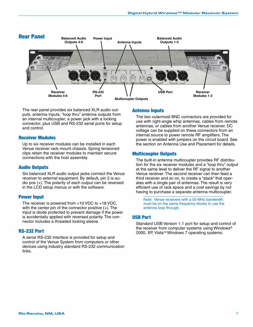
The rear panel provides six balanced XLR audio out-puts, antenna inputs, “loop thru” antenna outputs from an internal multicoupler, a power jack with a locking connector, plus USB and RS-232 serial ports for setup and control.
Receiver ModulesUp to six receiver modules can be installed in each Venue receiver rack mount chassis. Spring tensioned clips retain the receiver modules to maintain secure connections with the host assembly.
Audio OutputsSix balanced XLR audio output jacks connect the Venue receiver to external equipment. By default, pin 2 is au-dio pos (+). The polarity of each output can be reversed in the LCD setup menus or with the software.
Power InputThe receiver is powered from +10 VDC to +18 VDC, with the center pin of the connector positive (+). The input is diode protected to prevent damage if the power is accidentally applied with reversed polarity. The con-nector includes a threaded locking sleeve.
RS-232 PortA serial RS-232 interface is provided for setup and control of the Venue System from computers or other devices using industry standard RS-232 communication links.
Antenna InputsThe two outermost BNC connectors are provided for use with right-angle whip antennas, cables from remote antennas, or cables from another Venue receiver. DC voltage can be supplied on these connectors from an internal source to power remote RF amplifiers. The power is enabled with jumpers on the circuit board. See the section on Antenna Use and Placement for details.
Multicoupler OutputsThe built-in antenna multicoupler provides RF distribu-tion for the six receiver modules and a “loop thru” output at the same level to deliver the RF signal to another Venue receiver. The second receiver can then feed a third receiver and so on, to create a “stack” that oper-ates with a single pair of antennas. The result is very efficient use of rack space and a cost savings by not having to purchase a separate antenna multicoupler.
Note: Venue receivers with a 50 MHz bandwidth must be on the same frequency blocks to use the antenna loop through.
USB PortStandard USB Version 1.1 port for setup and control of the receiver from computer systems using Windows® 2000, XP, VistaTM Windows 7 operating systems.
Rear Panel
Multicoupler Outputs
Receiver Modules 4-6
Receiver Modules 1-3
USB PortRS-232 Port
Antenna InputsBalanced Audio
Outputs 1-3Balanced Audio
Outputs 4-6Power Input

Venue Wideband Receiver
LECTROSONICS, INC.8
Rack Installation1. Mount the receiver(s) in the desired rack location(s).
There are no special ventilation requirements.
2. Connect the antennas or coaxial cables to the antenna input connectors (outermost) on the rear panel.
Note: The frequency bandwidth of the antennas must cover the range of the modules in use.
3. For multiple unit installations, a “loop thru” is avail-able to feed two or three receivers from a single antenna pair. Connect coaxial cables from the mul-ticoupler outputs on the first receiver to the antenna inputs on the next receiver in the stack.
10.5-18VDC
RS-2326 5 4 LINK 2
3 2 1
IN USBIN OUT OUT
ANTENNA A
LINK 1 LINK 3
1
3
2 1
3
2 1
3
2
ANTENNA B
1
3
2 1
3
2 1
3
2
10.5-18VDC
RS-2326 5 4 LINK 2
3 2 1
IN USBIN OUT OUT
ANTENNA A
LINK 1 LINK 3
1
3
2 1
3
2 1
3
2
ANTENNA B
1
3
2 1
3
2 1
3
2
10.5-18VDC
RS-2326 5 4 LINK 2
3 2 1
IN USBIN OUT OUT
ANTENNA A
LINK 1 LINK 3
1
3
2 1
3
2 1
3
2
ANTENNA B
1
3
2 1
3
2 1
3
2
The outermost connectors are the inputs connected to the antennas on the first unit in the stack. The innermost connectors are the outputs that feed the next assembly in the rack.
4. Plug the power supply into a suitable outlet and plug the power connector into the Power Input Jack.
5. Turn down the audio inputs on all the externally connected equipment, then connect cables to the appropriate Audio Output XLR Jacks.
Audio OutputsBalanced XLR audio outputs on the rear panel can be used to drive balanced or unbalanced inputs at line level on any type of mixer, recorder or other type of audio equipment.
Note: When the modules are paired for diversity operation, the audio will appear at both XLR jacks associated with the module pair.
Hardware InstallationReceiver Modules
VRS and VRT receiver modules can be mixed in the same chassis, For ratio diversity operation, both mod-ules in the pair must be on the same frequency block and positioned in the assembly in keeping with the OPTI-BLEND labeling on top of the chassis housing.
All modules must be within the frequency passband of the host assembly. Frequency blocks are marked on the receiver module and chassis housings.
Installing Receiver Modules1. Turn the power off.
The receiver modules interface with the main as-sembly through multi-pin connectors on either side of the chassis. Insert the module straight down and then slide it toward the main housing to insert the connector pins. The module should sit flush against the side of the housing.
Caution: Make sure the connectors align correctly. Do not force the module onto the tab. Excessive force may damage the connectors.
2. Align the ridge on the retaining clip with the slot in the chassis and press the clip downward until the ridge snaps into the slot in the side panel.
Removing Receiver Modules1. Turn the power off.
2. Remove the retaining clip by pressing on it side-ways to release it from the slot in the side panel. Then pull upward to remove it.
3. Pull outward on the module to release the connec-tor and then lift it upward out of the chassis. Holes in the underside of the chassis allow you to grip the module on the top and bottom.
Front panel
Retaining clips
Digital Hybrid Wireless™ Modular Receiver System
Rio Rancho, NM, USA 9
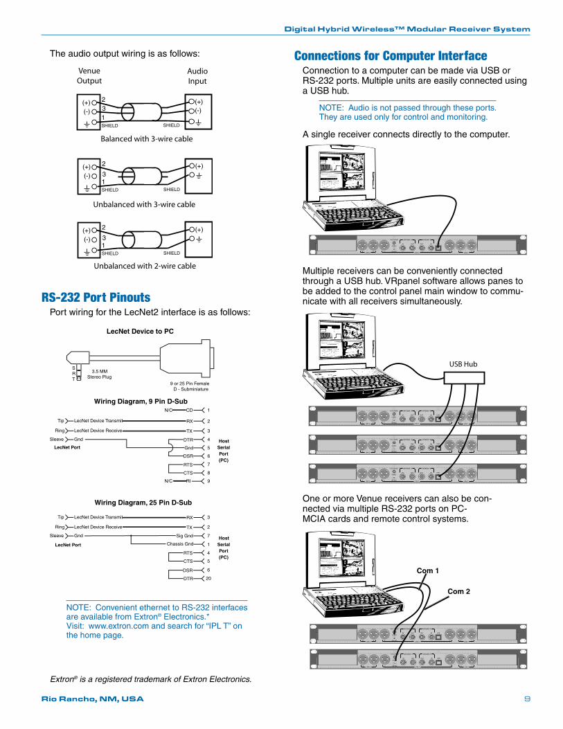
Connections for Computer InterfaceConnection to a computer can be made via USB or RS-232 ports. Multiple units are easily connected using a USB hub.
NOTE: Audio is not passed through these ports. They are used only for control and monitoring.
A single receiver connects directly to the computer.
10.5-18VDC
RS-2326 5 4 LINK 2
3 2 1
IN USBIN OUT OUT
ANTENNA A
LINK 1 LINK 3
1
3
2 1
3
2 1
3
2
ANTENNA B
1
3
2 1
3
2 1
3
2
Multiple receivers can be conveniently connected through a USB hub. VRpanel software allows panes to be added to the control panel main window to commu-nicate with all receivers simultaneously.
10.5-18VDC
RS-2326 5 4 LINK 2
3 2 1
IN USBIN OUT OUT
ANTENNA A
LINK 1 LINK 3
1
3
2 1
3
2 1
3
2
ANTENNA B
1
3
2 1
3
2 1
3
2
10.5-18VDC
RS-2326 5 4 LINK 2
3 2 1
IN USBIN OUT OUT
ANTENNA A
LINK 1 LINK 3
1
3
2 1
3
2 1
3
2
ANTENNA B
1
3
2 1
3
2 1
3
2
10.5-18VDC
RS-2326 5 4 LINK 2
3 2 1
IN USBIN OUT OUT
ANTENNA A
LINK 1 LINK 3
1
3
2 1
3
2 1
3
2
ANTENNA B
1
3
2 1
3
2 1
3
2
USB Hub
One or more Venue receivers can also be con-nected via multiple RS-232 ports on PC-MCIA cards and remote control systems.
10.5-18VDC
RS-2326 5 4 LINK 2
3 2 1
IN USBIN OUT OUT
ANTENNA A
LINK 1 LINK 3
1
3
2 1
3
2 1
3
2
ANTENNA B
1
3
2 1
3
2 1
3
2
10.5-18VDC
RS-2326 5 4 LINK 2
3 2 1
IN USBIN OUT OUT
ANTENNA A
LINK 1 LINK 3
1
3
2 1
3
2 1
3
2
ANTENNA B
1
3
2 1
3
2 1
3
2
The audio output wiring is as follows:
(+)
1(-)
SHIELD SHIELD
(+)(-)
23
(+)
1(-)
SHIELD SHIELD
(+)2
3
(+)
1(-)
SHIELD SHIELD
(+)2
3
VenueOutput
AudioInput
Balanced with 3-wire cable
Unbalanced with 3-wire cable
Unbalanced with 2-wire cable
RS-232 Port PinoutsPort wiring for the LecNet2 interface is as follows:
SRT
Wiring Diagram, 9 Pin D-SubN/C CD
LecNet Device Transmit RXTip
LecNet Device Receive TXRing
Gnd
Gnd
Sleeve DTR
DSR
RTS
CTS
Wiring Diagram, 25 Pin D-Sub
N/C RI
LecNet Device Transmit RXTip
LecNet Device Receive TXRing
Gnd
Chassis Gnd
Sleeve Sig Gnd
RTS
CTS
DSR
DTR
LecNet Port
9 or 25 Pin Female D - Subminiature
1
2
3
4
5
6
7
8
9
3
2
7
1
4
5
6
20
Host Serial Port (PC)
Host Serial Port (PC)
LecNet Port
3.5 MM Stereo Plug
LecNet Device to PC
NOTE: Convenient ethernet to RS-232 interfaces are available from Extron® Electronics.* Visit: www.extron.com and search for “IPL T” on the home page.
Com 1
Com 2
Extron® is a registered trademark of Extron Electronics.
Venue Wideband Receiver
LECTROSONICS, INC.10
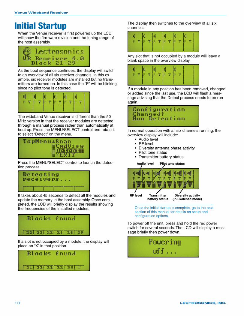
Initial StartupWhen the Venue receiver is first powered up the LCD will show the firmware revision and the tuning range of the host assembly.
As the boot sequence continues, the display will switch to an overview of all six receiver channels. In this ex-ample, six receiver modules are installed but no trans-mitters are turned on. In this case the “P” will be blinking since no pilot tone is detected.
The wideband Venue receiver is different than the 50 MHz version in that the receiver modules are detected through a manual process rather than automatically at bootup.PresstheMENU/SELECTcontrolandrotateitto select “Detect” on the menu.
PresstheMENU/SELECTcontroltolaunchthedetec-tion process.
It takes about 45 seconds to detect all the modules and update the memory in the host assembly. Once com-pleted, the LCD will briefly display the results showing the frequencies of the installed modules.
If a slot is not occupied by a module, the display will place an “X” in that position.
The display then switches to the overview of all six channels.
Any slot that is not occupied by a module will leave a blank space in the overview display.
If a module in any position has been removed, changed or added since the last use, the LCD will flash a mes-sage advising that the Detect process needs to be run again.
In normal operation with all six channels running, the overview display will include: • Audiolevel • RFlevel • Diversityantennaphaseactivity • Pilottonestatus • Transmitterbatterystatus
Audio level
RF level Transmitter battery status
Pilot tone status
Diversity activity (in Switched mode)
Once the initial startup is complete, go to the next section of this manual for details on setup and configuration options.
To power off the unit, press and hold the red power switch for several seconds. The LCD will display a mes-sage briefly then power down.
Digital Hybrid Wireless™ Modular Receiver System
Rio Rancho, NM, USA 11
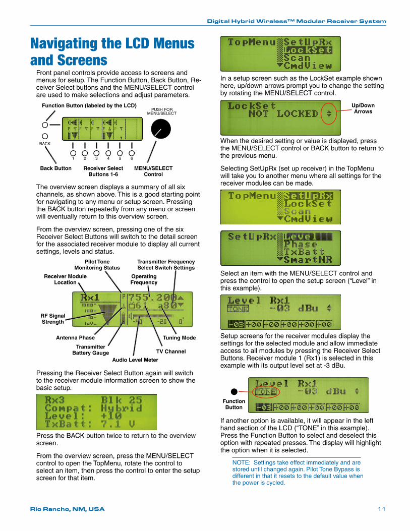
Navigating the LCD Menus and Screens
Front panel controls provide access to screens and menus for setup. The Function Button, Back Button, Re-ceiverSelectbuttonsandtheMENU/SELECTcontrolare used to make selections and adjust parameters.
Function Button (labeled by the LCD)
Back Button Receiver Select Buttons 1-6
MENU/SELECT Control
The overview screen displays a summary of all six channels, as shown above. This is a good starting point for navigating to any menu or setup screen. Pressing the BACK button repeatedly from any menu or screen will eventually return to this overview screen.
From the overview screen, pressing one of the six Receiver Select Buttons will switch to the detail screen for the associated receiver module to display all current settings, levels and status.
Receiver Module Location
Pilot Tone Monitoring Status
Operating Frequency
RF Signal Strength
Antenna Phase
Transmitter Battery Gauge TV Channel
Audio Level Meter
Tuning Mode
Transmitter Frequency Select Switch Settings
Pressing the Receiver Select Button again will switch to the receiver module information screen to show the basic setup.
Press the BACK button twice to return to the overview screen.
Fromtheoverviewscreen,presstheMENU/SELECTcontrol to open the TopMenu, rotate the control to select an item, then press the control to enter the setup screen for that item.
In a setup screen such as the LockSet example shown here,up/downarrowspromptyoutochangethesettingbyrotatingtheMENU/SELECTcontrol.
Up/Down Arrows
When the desired setting or value is displayed, press theMENU/SELECTcontrolorBACKbuttontoreturntothe previous menu.
Selecting SetUpRx (set up receiver) in the TopMenu will take you to another menu where all settings for the receiver modules can be made.
SelectanitemwiththeMENU/SELECTcontrolandpress the control to open the setup screen (“Level” in this example).
Setup screens for the receiver modules display the settings for the selected module and allow immediate access to all modules by pressing the Receiver Select Buttons. Receiver module 1 (Rx1) is selected in this example with its output level set at -3 dBu.
Function Button
If another option is available, it will appear in the left hand section of the LCD (“TONE” in this example). Press the Function Button to select and deselect this option with repeated presses. The display will highlight the option when it is selected.
NOTE: Settings take effect immediately and are stored until changed again. Pilot Tone Bypass is different in that it resets to the default value when the power is cycled.
Venue Wideband Receiver
LECTROSONICS, INC.12
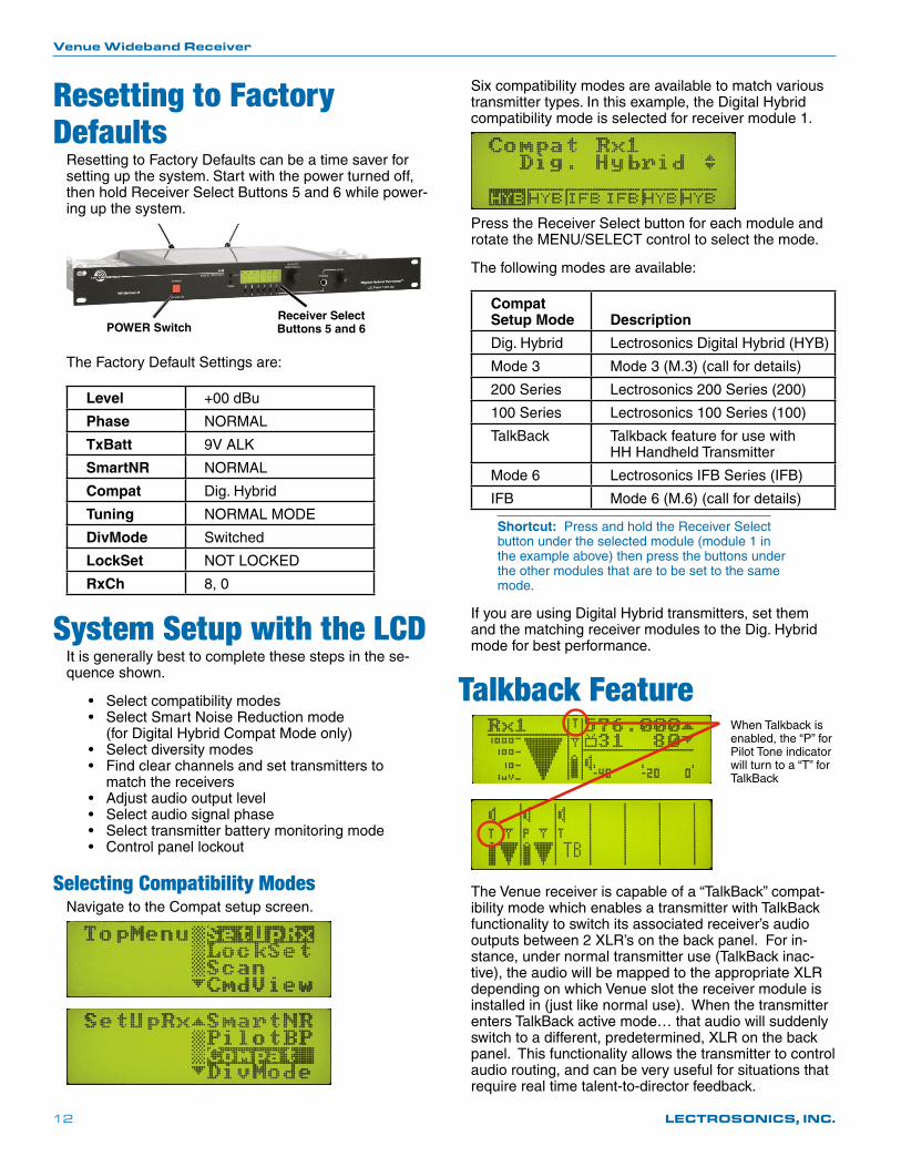
Resetting to Factory Defaults
Resetting to Factory Defaults can be a time saver for setting up the system. Start with the power turned off, then hold Receiver Select Buttons 5 and 6 while power-ing up the system.
POWER SwitchReceiver Select Buttons 5 and 6
The Factory Default Settings are:
Level +00 dBu
Phase NORMAL
TxBatt 9V ALK
SmartNR NORMAL
Compat Dig. Hybrid
Tuning NORMAL MODE
DivMode Switched
LockSet NOT LOCKED
RxCh 8, 0
System Setup with the LCDIt is generally best to complete these steps in the se-quence shown.
• Selectcompatibilitymodes • SelectSmartNoiseReductionmode (for Digital Hybrid Compat Mode only) • Selectdiversitymodes • Findclearchannelsandsettransmittersto match the receivers • Adjustaudiooutputlevel • Selectaudiosignalphase • Selecttransmitterbatterymonitoringmode • Controlpanellockout
Selecting Compatibility ModesNavigate to the Compat setup screen.
Six compatibility modes are available to match various transmitter types. In this example, the Digital Hybrid compatibility mode is selected for receiver module 1.
Press the Receiver Select button for each module and rotatetheMENU/SELECTcontroltoselectthemode.
The following modes are available:
Compat Setup Mode
Description
Dig. Hybrid Lectrosonics Digital Hybrid (HYB)
Mode 3 Mode 3 (M.3) (call for details)
200 Series Lectrosonics 200 Series (200)
100 Series Lectrosonics 100 Series (100)
TalkBack Talkback feature for use with HH Handheld Transmitter
Mode 6 Lectrosonics IFB Series (IFB)
IFB Mode 6 (M.6) (call for details)
Shortcut: Press and hold the Receiver Select button under the selected module (module 1 in the example above) then press the buttons under the other modules that are to be set to the same mode.
If you are using Digital Hybrid transmitters, set them and the matching receiver modules to the Dig. Hybrid mode for best performance.
Talkback FeatureWhen Talkback is enabled, the “P” for Pilot Tone indicator will turn to a “T” for TalkBack
The Venue receiver is capable of a “TalkBack” compat-ibility mode which enables a transmitter with TalkBack functionality to switch its associated receiver’s audio outputs between 2 XLR’s on the back panel. For in-stance, under normal transmitter use (TalkBack inac-tive), the audio will be mapped to the appropriate XLR depending on which Venue slot the receiver module is installed in (just like normal use). When the transmitter enters TalkBack active mode… that audio will suddenly switch to a different, predetermined, XLR on the back panel. This functionality allows the transmitter to control audio routing, and can be very useful for situations that require real time talent-to-director feedback.
Digital Hybrid Wireless™ Modular Receiver System
Rio Rancho, NM, USA 13
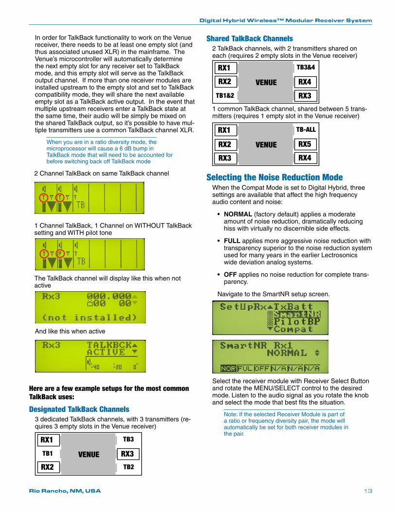
In order for TalkBack functionality to work on the Venue receiver, there needs to be at least one empty slot (and thus associated unused XLR) in the mainframe. The Venue’s microcontroller will automatically determine the next empty slot for any receiver set to TalkBack mode, and this empty slot will serve as the TalkBack output channel. If more than one receiver modules are installed upstream to the empty slot and set to TalkBack compatibility mode, they will share the next available empty slot as a TalkBack active output. In the event that multiple upstream receivers enter a TalkBack state at the same time, their audio will be simply be mixed on the shared TalkBack output, so it’s possible to have mul-tiple transmitters use a common TalkBack channel XLR.
When you are in a ratio diversity mode, the microprocessor will cause a 6 dB bump in TalkBack mode that will need to be accounted for before switching back off TalkBack mode
2 Channel TalkBack on same TalkBack channel
1 Channel TalkBack, 1 Channel on WITHOUT TalkBack setting and WITH pilot tone
The TalkBack channel will display like this when not active
And like this when active
Here are a few example setups for the most common TalkBack uses:
Designated TalkBack Channels3 dedicated TalkBack channels, with 3 transmitters (re-quires 3 empty slots in the Venue receiver)
VENUE
RX1
RX2
RX3TB1
TB3
TB2
Shared TalkBack Channels2 TalkBack channels, with 2 transmitters shared on each (requires 2 empty slots in the Venue receiver)
VENUE
RX1
RX2 RX4
TB1&2
TB3&4
RX3
1 common TalkBack channel, shared between 5 trans-mitters (requires 1 empty slot in the Venue receiver)
VENUE
RX1
RX2 RX5
TB-ALL
RX3 RX4
Selecting the Noise Reduction ModeWhen the Compat Mode is set to Digital Hybrid, three settings are available that affect the high frequency audio content and noise:
• NORMAL(factory default) applies a moderate amount of noise reduction, dramatically reducing hiss with virtually no discernible side effects.
• FULL applies more aggressive noise reduction with transparency superior to the noise reduction system used for many years in the earlier Lectrosonics wide deviation analog systems.
• OFF applies no noise reduction for complete trans-parency.
Navigate to the SmartNR setup screen.
Select the receiver module with Receiver Select Button androtatetheMENU/SELECTcontroltothedesiredmode. Listen to the audio signal as you rotate the knob and select the mode that best fits the situation.
Note: If the selected Receiver Module is part of a ratio or frequency diversity pair, the mode will automatically be set for both receiver modules in the pair.
Venue Wideband Receiver
LECTROSONICS, INC.14
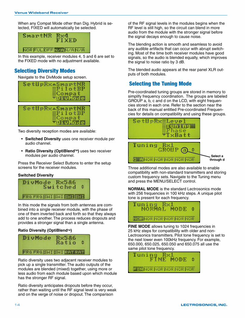
When any Compat Mode other than Dig. Hybrid is se-lected, FIXED will automatically be selected.
In this example, receiver modules 4, 5 and 6 are set to the FIXED mode with no adjustment available.
Selecting Diversity ModesNavigate to the DivMode setup screen.
Two diversity reception modes are available:
• Switched Diversity uses one receiver module per audio channel.
• Ratio Diversity (OptiBlendTM) uses two receiver modules per audio channel.
Press the Receiver Select Buttons to enter the setup screens for the receiver modules.
Switched Diversity
In this mode the signals from both antennas are com-bined into a single receiver module, with the phase of one of them inverted back and forth so that they always add to one another. The process reduces dropouts and provides a stronger signal than a single antenna.
Ratio Diversity (OptiBlendTM)
Ratio diversity uses two adjacent receiver modules to pick up a single transmitter. The audio outputs of the modules are blended (mixed) together, using more or less audio from each module based upon which module has the stronger RF signal.
Ratio diversity anticipates dropouts before they occur, rather than waiting until the RF signal level is very weak and on the verge of noise or dropout. The comparison
of the RF signal levels in the modules begins when the RF level is still high, so the circuit can blend in more audio from the module with the stronger signal before the signal decays enough to cause noise.
The blending action is smooth and seamless to avoid any audible artifacts that can occur with abrupt switch-ing. Most of the time both receiver modules have good signals, so the audio is blended equally, which improves the signal to noise ratio by 3 dB.
The blended audio appears at the rear panel XLR out-puts of both modules.
Selecting the Tuning ModePre-coordinated tuning groups are stored in memory to simplify frequency coordination. The groups are labeled GROUP a, b, c and d on the LCD, with eight frequen-cies stored in each one. Refer to the section near the back of this manual entitled Pre-coordinated Frequen-cies for details on compatibility and using these groups.
Select a through d
Three additional modes are also available to enable compatibility with non-standard transmitters and storing custom frequency sets. Navigate to the Tuning menu andpresstheMENU/SELECTcontrol.
NORMAL MODE is the standard Lectrosonics mode with 256 frequencies in 100 kHz steps. A unique pilot tone is present for each frequency.
FINE MODE allows tuning to 1024 frequencies in 25 kHz steps for compatibility with older and non-Lectrosonics transmitters. Pilot tone frequency is set to the next lower even 100kHz frequency. For example, 650.000, 650.025, 650.050 and 650.075 all use the same pilot tone frequency.
Digital Hybrid Wireless™ Modular Receiver System
Rio Rancho, NM, USA 15
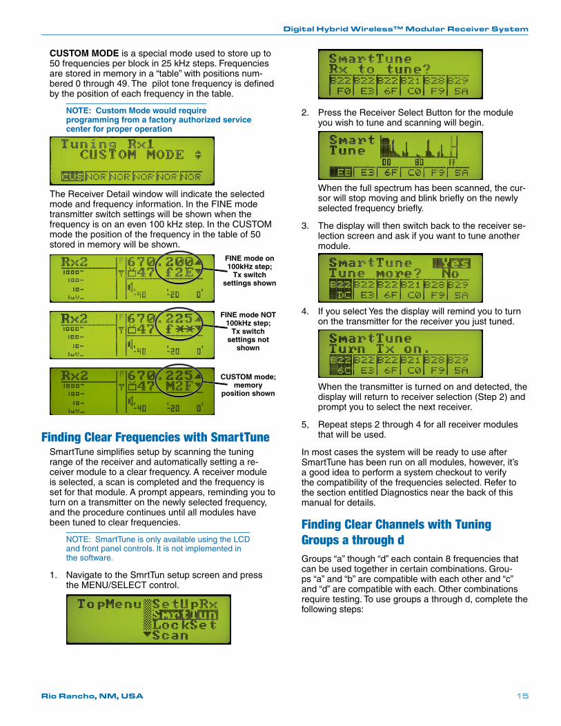
CUSTOM MODE is a special mode used to store up to 50 frequencies per block in 25 kHz steps. Frequencies are stored in memory in a “table” with positions num-bered 0 through 49. The pilot tone frequency is defined by the position of each frequency in the table.
NOTE: Custom Mode would require programming from a factory authorized service center for proper operation
The Receiver Detail window will indicate the selected mode and frequency information. In the FINE mode transmitter switch settings will be shown when the frequency is on an even 100 kHz step. In the CUSTOM mode the position of the frequency in the table of 50 stored in memory will be shown.
FINE mode on 100kHz step;
Tx switch settings shown
FINE mode NOT 100kHz step;
Tx switch settings not
shown
CUSTOM mode; memory
position shown
Finding Clear Frequencies with SmartTuneSmartTune simplifies setup by scanning the tuning range of the receiver and automatically setting a re-ceiver module to a clear frequency. A receiver module is selected, a scan is completed and the frequency is set for that module. A prompt appears, reminding you to turn on a transmitter on the newly selected frequency, and the procedure continues until all modules have been tuned to clear frequencies.
NOTE: SmartTune is only available using the LCD and front panel controls. It is not implemented in the software.
1. Navigate to the SmrtTun setup screen and press theMENU/SELECTcontrol.
2. Press the Receiver Select Button for the module you wish to tune and scanning will begin.
When the full spectrum has been scanned, the cur-sor will stop moving and blink briefly on the newly selected frequency briefly.
3. The display will then switch back to the receiver se-lection screen and ask if you want to tune another module.
4. If you select Yes the display will remind you to turn on the transmitter for the receiver you just tuned.
When the transmitter is turned on and detected, the display will return to receiver selection (Step 2) and prompt you to select the next receiver.
5, Repeat steps 2 through 4 for all receiver modules that will be used.
In most cases the system will be ready to use after SmartTune has been run on all modules, however, it’s a good idea to perform a system checkout to verify the compatibility of the frequencies selected. Refer to the section entitled Diagnostics near the back of this manual for details.
Finding Clear Channels with Tuning Groups a through dGroups “a” though “d” each contain 8 frequencies that can be used together in certain combinations. Grou-ps “a” and “b” are compatible with each other and “c” and “d” are compatible with each. Other combinations require testing. To use groups a through d, complete the following steps:
Venue Wideband Receiver
LECTROSONICS, INC.16
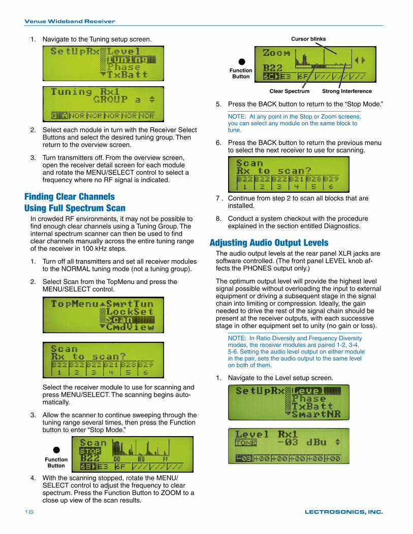
1. Navigate to the Tuning setup screen.
2. Select each module in turn with the Receiver Select Buttons and select the desired tuning group. Then return to the overview screen.
3. Turn transmitters off. From the overview screen, open the receiver detail screen for each module androtatetheMENU/SELECTcontroltoselectafrequency where no RF signal is indicated.
Finding Clear Channels Using Full Spectrum Scan
In crowded RF environments, it may not be possible to find enough clear channels using a Tuning Group. The internal spectrum scanner can then be used to find clear channels manually across the entire tuning range of the receiver in 100 kHz steps.
1. Turn off all transmitters and set all receiver modules to the NORMAL tuning mode (not a tuning group).
2. Select Scan from the TopMenu and press the MENU/SELECTcontrol.
Select the receiver module to use for scanning and pressMENU/SELECT.Thescanningbeginsauto-matically.
3. Allow the scanner to continue sweeping through the tuning range several times, then press the Function button to enter “Stop Mode.”
Function Button
4. Withthescanningstopped,rotatetheMENU/SELECT control to adjust the frequency to clear spectrum. Press the Function Button to ZOOM to a close up view of the scan results.
Function Button
Cursor blinks
Strong InterferenceClear Spectrum
5. Press the BACK button to return to the “Stop Mode.”
NOTE: At any point in the Stop or Zoom screens, you can select any module on the same block to tune.
6. Press the BACK button to return the previous menu to select the next receiver to use for scanning.
7 . Continue from step 2 to scan all blocks that are installed.
8. Conduct a system checkout with the procedure explained in the section entitled Diagnostics.
Adjusting Audio Output LevelsThe audio output levels at the rear panel XLR jacks are software controlled. (The front panel LEVEL knob af-fects the PHONES output only.)
The optimum output level will provide the highest level signal possible without overloading the input to external equipment or driving a subsequent stage in the signal chain into limiting or compression. Ideally, the gain needed to drive the rest of the signal chain should be present at the receiver outputs, with each successive stage in other equipment set to unity (no gain or loss).
NOTE: In Ratio Diversity and Frequency Diversity modes, the receiver modules are paired 1-2, 3-4, 5-6. Setting the audio level output on either module in the pair, sets the audio output to the same level on both of them.
1. Navigate to the Level setup screen.
Digital Hybrid Wireless™ Modular Receiver System
Rio Rancho, NM, USA 17
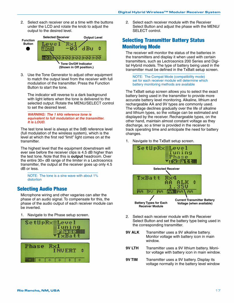
2. Select each receiver one at a time with the buttons under the LCD and rotate the knob to adjust the output to the desired level.
Selected Receiver Output Level
Tone On/Off Indicator (Shown in Off position.)
Function Button
3. Use the Tone Generator to adjust other equipment to match the output level from the receiver with full modulation of the transmitter. Press the Function Button to start the tone.
The indicator will reverse to a dark background with light letters when the tone is delivered to the selectedoutput.RotatetheMENU/SELECTcontrolto set the desired level.
WARNING: The 1 kHz reference tone is equivalent to full modulation at the transmitter. It is LOUD.
The test tone level is always at the 0dB reference level (full modulation of the wireless system), which is the level at which the first red “limit” light comes on at the transmitter.
The highest level that the equipment downstream will ever see before the receiver clips is 4.5 dB higher than the test tone. Note that this is output headroom. Over the entire 30+ dB range of the limiter in a Lectrosonics transmitter, the output at the receiver goes up only 4.5 dB or less.
NOTE: The tone is a sine wave with about 1% distortion
Selecting Audio PhaseMicrophone wiring and other vagaries can alter the phase of an audio signal. To compensate for this, the phase of the audio output of each receiver module can be inverted.
1. Navigate to the Phase setup screen.
2. Select each receiver module with the Receiver SelectButtonandadjustthephasewiththeMENU/SELECT control.
Selecting Transmitter Battery Status Monitoring Mode
The receiver will monitor the status of the batteries in the transmitters and display it when used with certain transmitters, such as Lectrosonics 200 Series and Digi-tal Hybrid models. The type of battery being used in the transmitter must be defined in the TxBatt setup screen.
NOTE: The Compat Mode (compatibility mode) set for each receiver module will determine which battery monitoring methods are available
The TxBatt setup screen allows you to select the exact battery being used in the transmitter to provide more accurate battery level monitoring. Alkaline, lithium and rechargeable AA and 9V types are commonly used. The voltage declines gradually over the life of alkaline and lithium types, so the voltage can be estimated and displayed by the receiver. Rechargeable types, on the other hand, maintain almost constant voltage as they discharge, so a timer is provided in the receiver to track operating time and anticipate the need for battery changes.
1. Navigate to the TxBatt setup screen.
Selected Receiver
Battery Types for Each Receiver Module
Current Transmitter Battery Voltage (when available)
2. Select each receiver module with the Receiver Select Button and set the battery type being used in the corresponding transmitter.
9V ALK Transmitter uses a 9V alkaline battery. Monitor voltage with battery icon in main window.
9V LTH Transmitter uses a 9V lithium battery. Moni-tor voltage with battery icon in main window.
9V TIM Transmitter uses a 9V battery. Display its voltage normally in the battery level window
Venue Wideband Receiver
LECTROSONICS, INC.18
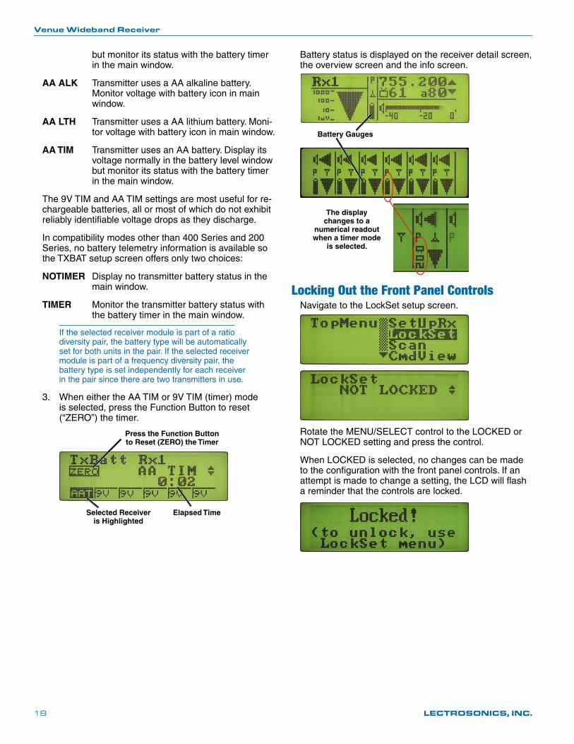
but monitor its status with the battery timer in the main window.
AA ALK Transmitter uses a AA alkaline battery. Monitor voltage with battery icon in main window.
AA LTH Transmitter uses a AA lithium battery. Moni-tor voltage with battery icon in main window.
AA TIM Transmitter uses an AA battery. Display its voltage normally in the battery level window but monitor its status with the battery timer in the main window.
The 9V TIM and AA TIM settings are most useful for re-chargeable batteries, all or most of which do not exhibit reliably identifiable voltage drops as they discharge.
In compatibility modes other than 400 Series and 200 Series, no battery telemetry information is available so the TXBAT setup screen offers only two choices:
NOTIMER Display no transmitter battery status in the main window.
TIMER Monitor the transmitter battery status with the battery timer in the main window.
If the selected receiver module is part of a ratio diversity pair, the battery type will be automatically set for both units in the pair. If the selected receiver module is part of a frequency diversity pair, the battery type is set independently for each receiver in the pair since there are two transmitters in use.
3. When either the AA TIM or 9V TIM (timer) mode is selected, press the Function Button to reset (“ZERO”) the timer.
Elapsed Time
Press the Function Button to Reset (ZERO) the Timer
Selected Receiver is Highlighted
Battery status is displayed on the receiver detail screen, the overview screen and the info screen.
Battery Gauges
The display changes to a
numerical readout when a timer mode
is selected.
Locking Out the Front Panel ControlsNavigate to the LockSet setup screen.
RotatetheMENU/SELECTcontroltotheLOCKEDorNOT LOCKED setting and press the control.
When LOCKED is selected, no changes can be made to the configuration with the front panel controls. If an attempt is made to change a setting, the LCD will flash a reminder that the controls are locked.
Digital Hybrid Wireless™ Modular Receiver System
Rio Rancho, NM, USA 19
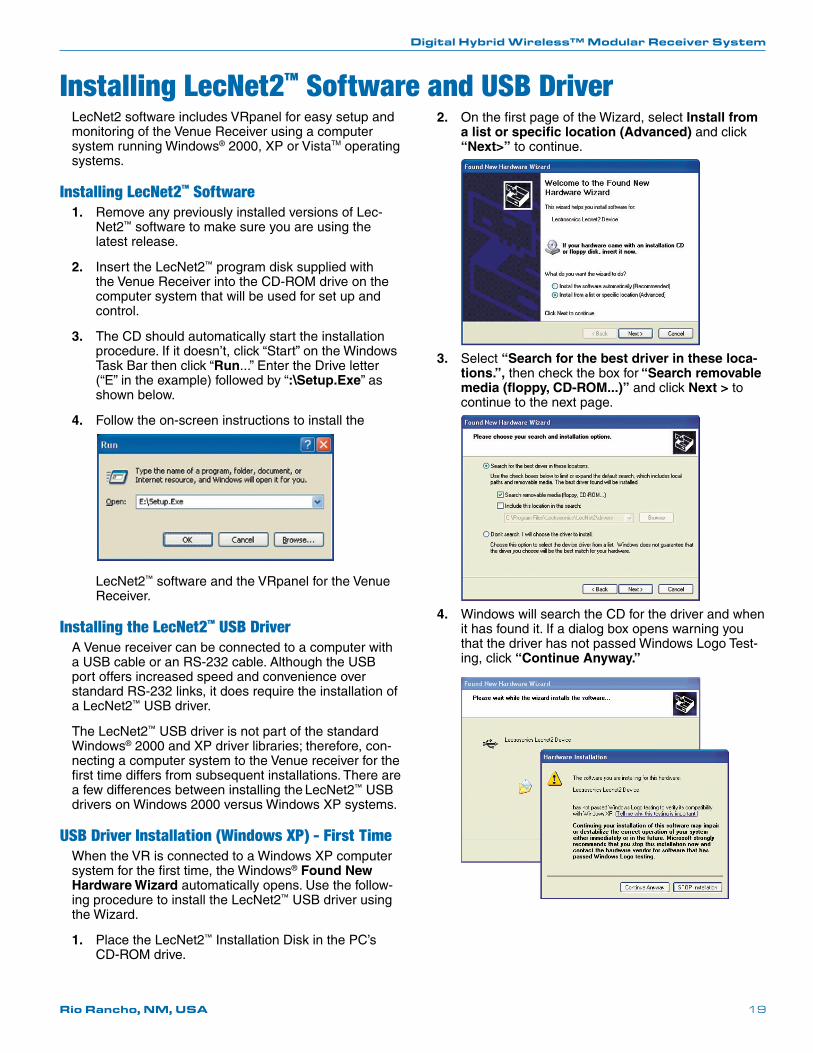
2. On the first page of the Wizard, select Install from a list or specific location (Advanced) and click “Next>” to continue.
3. Select “Search for the best driver in these loca-tions.”, then check the box for “Search removable media (floppy, CD-ROM...)” and click Next > to continue to the next page.
4. Windows will search the CD for the driver and when it has found it. If a dialog box opens warning you that the driver has not passed Windows Logo Test-ing, click “Continue Anyway.”
Installing LecNet2™ Software and USB DriverLecNet2 software includes VRpanel for easy setup and monitoring of the Venue Receiver using a computer system running Windows® 2000, XP or VistaTM operating systems.
Installing LecNet2™ Software1. Remove any previously installed versions of Lec-
Net2™ software to make sure you are using the latest release.
2. Insert the LecNet2™ program disk supplied with the Venue Receiver into the CD-ROM drive on the computer system that will be used for set up and control.
3. The CD should automatically start the installation procedure. If it doesn’t, click “Start” on the Windows Task Bar then click “Run...” Enter the Drive letter (“E” in the example) followed by “:\Setup.Exe” as shown below.
4. Follow the on-screen instructions to install the
LecNet2™ software and the VRpanel for the Venue Receiver.
Installing the LecNet2™ USB DriverA Venue receiver can be connected to a computer with a USB cable or an RS-232 cable. Although the USB port offers increased speed and convenience over standard RS-232 links, it does require the installation of a LecNet2™ USB driver.
The LecNet2™ USB driver is not part of the standard Windows® 2000 and XP driver libraries; therefore, con-necting a computer system to the Venue receiver for the first time differs from subsequent installations. There are a few differences between installing the LecNet2™ USB drivers on Windows 2000 versus Windows XP systems.
USB Driver Installation (Windows XP) - First TimeWhen the VR is connected to a Windows XP computer system for the first time, the Windows® Found New Hardware Wizard automatically opens. Use the follow-ing procedure to install the LecNet2™ USB driver using the Wizard.
1. Place the LecNet2™ Installation Disk in the PC’s CD-ROM drive.
Venue Wideband Receiver
LECTROSONICS, INC.20
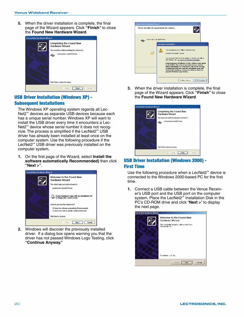
3. When the driver installation is complete, the final page of the Wizard appears. Click “Finish” to close the Found New Hardware Wizard.
USB Driver Installation (Windows 2000) - First Time
Use the following procedure when a LecNet2™ device is connected to the Windows 2000-based PC for the first time.
1. Connect a USB cable between the Venue Receiv-er’s USB port and the USB port on the computer system. Place the LecNet2™ Installation Disk in the PC’s CD-ROM drive and click “Next >” to display the next page.
5. When the driver installation is complete, the final page of the Wizard appears. Click “Finish” to close the Found New Hardware Wizard.
USB Driver Installation (Windows XP) - Subsequent Installations
The Windows XP operating system regards all Lec-Net2™ devices as separate USB devices because each has a unique serial number. Windows XP will want to install the USB driver every time it encounters a Lec-Net2™ device whose serial number it does not recog-nize. The process is simplified if the LecNet2™ USB driver has already been installed at least once on the computer system. Use the following procedure if the LecNet2™ USB driver was previously installed on the computer system.
1. On the first page of the Wizard, select Install the software automatically Recommended) then click “Next >”.
2. Windows will discover the previously installed driver. If a dialog box opens warning you that the driver has not passed Windows Logo Testing, click “Continue Anyway.”

Digital Hybrid Wireless™ Modular Receiver System
Rio Rancho, NM, USA 21
2. Select Search for a suitable driver for my device (recommended) and click “Next >” to continue.
3. Check only CD-ROM drives then click “Next >” to search the LecNet2™ CD for the USB driver.
4. When the driver is found, the LecNet2™ device name will be displayed along with the location of the driver. Click “Next >” to install the driver.
5. Click “Finish” when the installation is complete.
USB Driver Installation (Windows 2000) Subsequent Installations
Once the LecNet2™ USB driver is installed in a Win-dows® 2000 system device, subsequent LectNet2 USB devices will invoke the Found New Hardware Wizard which will automatically load the LecNet2™ USB driver for the new device.
Firmware Update Instructions
First you need to download the most recent firmware from the web site.
http://www.lectrosonics.com/LecNet2/
Scroll down to Firmware Updates. Be sure to select the correct version for the receiver - narrowband, wideband or 944. Place the file on your local drive then unzip it.
The update instructions are in the Help section of the software. Launch theLecNet2 software and open the help file. Select “Advanced Topics,” then “Using the Update Wizard.”
The receiver will have to be opened in the update mode - button press sequence is in the help file instructions.
Venue Wideband Receiver
LECTROSONICS, INC.22
Setting Up the Venue Receiver Using VRpanelOnce the LecNet2™ software and USB drivers have been installed, the Venue receiver can be configured with a software interface and a computer using a Win-dows® 2000, XP or VistaTM operating system.
VRpanel is an intuitive software package that simplifies the setup and operation of the Venue receiver. This sec-tion of this manual is limited to the basic setup and con-figuration. More detailed explanations concerning usage and configuration are contained in the online Help.
The online Help also documents the serial commands used by external devices, including AMX® and Crestron® remote control systems, that can be used to control the Venue system.
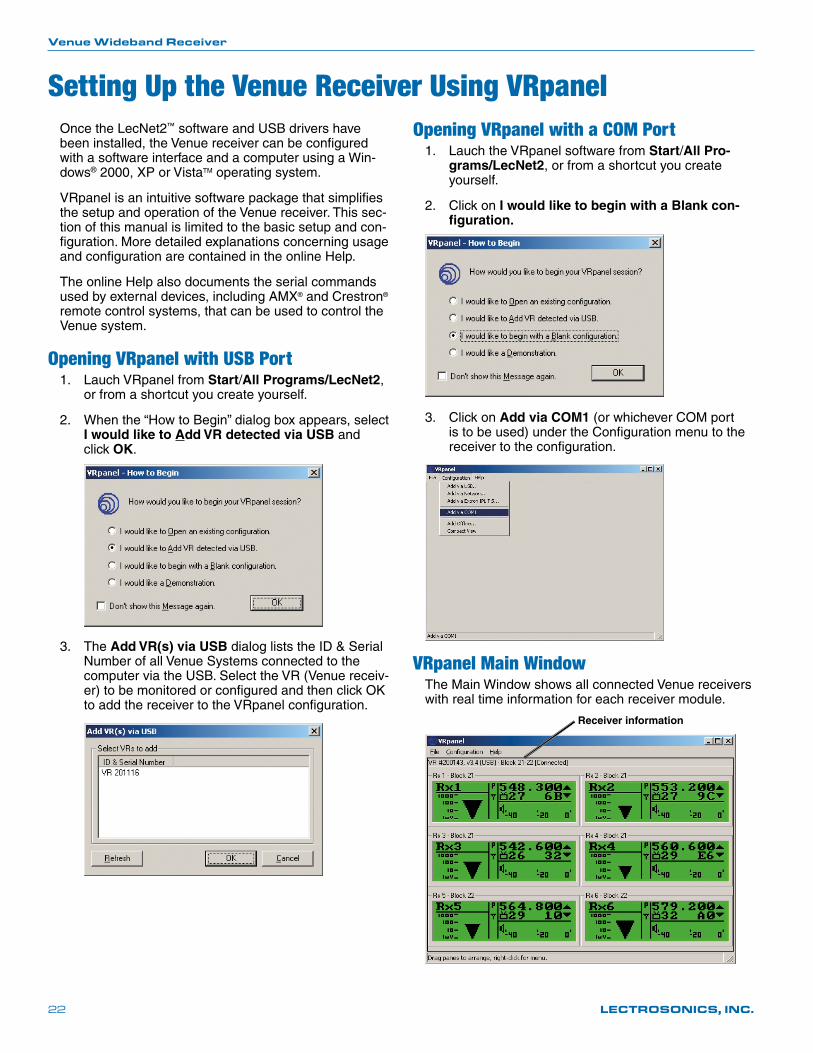
Opening VRpanel with USB Port1. Lauch VRpanel from Start/All Programs/LecNet2,
or from a shortcut you create yourself.
2. When the “How to Begin” dialog box appears, select I would like to Add VR detected via USB and click OK.
3. The Add VR(s) via USB dialog lists the ID & Serial Number of all Venue Systems connected to the computer via the USB. Select the VR (Venue receiv-er) to be monitored or configured and then click OK to add the receiver to the VRpanel configuration.
Opening VRpanel with a COM Port1. Lauch the VRpanel software from Start/All Pro-
grams/LecNet2, or from a shortcut you create yourself.
2. Click on I would like to begin with a Blank con-figuration.
3. Click on Add via COM1 (or whichever COM port is to be used) under the Configuration menu to the receiver to the configuration.
VRpanel Main WindowThe Main Window shows all connected Venue receivers with real time information for each receiver module.
Receiver information
Digital Hybrid Wireless™ Modular Receiver System
Rio Rancho, NM, USA 23
Main Window Top Menu ItemsThe Main Window is organized in a straightforward manner with three pull down menus. Brief descriptions of these menus are presented here as an introduction. Full descriptions and instructions for the menu items are presented in the online Help.
With multiple Venue receivers, a pane opens for each receiver, with positions for up to six receiver modules in each. This lets you view and control all wireless sys-tems simultaneously on a single computer screen.
File Menu
Items under the File Menu allow you to create, store and retrieve configu-rations from files stored on disk, and to update the firmware. Open Offline opens a configuration stored on disk without having hardware connected. See the online Help for more infor-mation pertaining to these items.
Configuration Menu
Connections to the Venue receiver via USB, a COM port, Network or an Extron IPL TS ethernet adapter are enabled in this menu. Compact View reduces the size of objects in the main window, allowing more Venue receivers to be moni-tored and controlled at the same
time. Add Offline lets you add another Venue receiver to the configuration without having the hardware. See the online Help for more information pertaining to these items.
Help Menu
The items in this menu open the online Help, turn on and off a demon-stration mode for VRpanel and view the software version information.
Popup Menu ItemsRight clicking anywhere in a receiver pane invokes a context-sensitive and position-sensitive popup menu. From there it is possible to alter settings, add or delete a Venue receiver from VRpanel, perform a spectrum scan, start the Walk Test Recorder and more.
NOTE: Right clicking is the key to successful VRpanel operation!
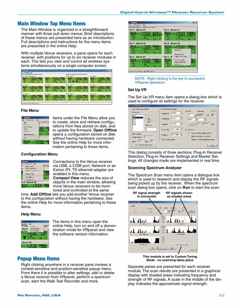
Set Up VR
The Set Up VR menu item opens a dialog box which is used to configure all settings for the receiver.
This dialog consists of three sections: Plug-In Receiver Selection, Plug-In Receiver Settings and Master Set-tings. All changes made are implemented in real time.
Scanning Spectrum Analyzer
The Spectrum Scan menu item opens a dialogue box which is used to research and display the RF signals being picked up by the receiver. When the spectrum scan dialog box opens, click on Run to start the scan.
RF signals shown as shaded areas
RF signal strength in microvolts
This module is set to Custom Tuning Mode - no scanning takes place
Separate panes are presented for each receiver module. The scan results are presented in a graphical display with shaded areas indicating frequency and strength of RF signals. A scale in the middle of the dis-play indicates the approximate signal strength.

Venue Wideband Receiver
LECTROSONICS, INC.24
Scanning continues until it is suspended by the user. Click Stop to suspend the scanning. While scanning is suspended, select a receiver module with its radio button in the upper left of the dialog box. The cursor for the selected module will be highlighted, and can then be moved by left clicking and dragging the mouse. Click Run to resume the scan. Click Clear to stop the scan and clear the spectrum data. The behavior of these but-tons is the same regardless of whether or not the scan is “complete.”
Move all cursors into clear areas between the RF
signals as shown in these two
examples
Receiver select buttons
To avoid interference from external signals, the cur-sors should be placed in between the RF signals, as they are in the illustration above. To avoid interference caused by the systems themselves, refer to the sections entitled Pre-coordinated Frequencies and Diagnostics for details on multi-channel compatibility and testing.
Walk Test Recorder
This menu item opens a dialog box providing a con-venient method for testing the operation of selected receiver modules (or receiver module pairs) with the corresponding transmitters.
The Walk Test Recorder produces a chart recording of RF signal strength versus time. Receiver modules in switched diversity mode leave a single trace; diversity pairs leave dual traces.
An audio recording can be made while the recorder is running using the MC65 cable supplied with unit. Con-nect the PHONES jack output on the Venue Receiver front panel to the computer system’s audio input. Adjust the output level of the receiver with the LEVEL control on the front panel.
Click the Record button (red circle) to start the Walk Test Recorder and the Stop button (black square) to stop the recording process. Press the Play (green triangle) to play back the recording. Rewind and Fast Forward buttons move the window to the beginning and end of the chart. The cursor can also be moved with the computer mouse by clicking and dragging.
During the walk test, it helps to describe the location of the transmitter, e.g. “now going through the blue door,” “now passing the front gate,” etc. during the recording to make it easier to discern the bad locations. Start the playback of walk test and audio recordings from the be-ginning and observe the chart recording while you listen to the audio recording.
Factory Defaults
Clicking this item in the popup menu restores the se-lected Venue System to the factory default settings.
The Factory Default Settings are:
Level +00 dBu
Phase NORMAL
TxBatt 9V ALK
SmartNR NORMAL
Compat Dig. Hybrid
Tuning NORMAL MODE
DivMode Switched
LockSet NOT LOCKED
RxCh 8, 0
Custom Channels
Click on this item to open a dialog box allowing you to create, save and edit customized frequency sets.
Right click on each line to open the
editing dialog box and make
selections.
Refer to the Online Help for
details.
Delete VR
Click on Delete VR in the popup menu to delete the selected Venue receiver from the current VRpanel con-figuration.
Digital Hybrid Wireless™ Modular Receiver System
Rio Rancho, NM, USA 25
VRM
Jumpers settowards the center
to enable antenna power
DC Power to UFM230 DC Power to UFM230
UFM230 UFM230
Long coax cabl e Long coax cabl e
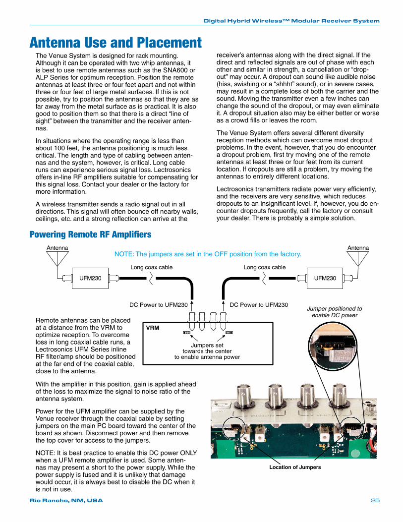
AntennaAntennaNOTE: The jumpers are set in the OFF position from the factory.
Location of Jumpers
Jumper positioned to enable DC power
The Venue System is designed for rack mounting. Although it can be operated with two whip antennas, it is best to use remote antennas such as the SNA600 or ALP Series for optimum reception. Position the remote antennas at least three or four feet apart and not within three or four feet of large metal surfaces. If this is not possible, try to position the antennas so that they are as far away from the metal surface as is practical. It is also good to position them so that there is a direct “line of sight” between the transmitter and the receiver anten-nas.
In situations where the operating range is less than about 100 feet, the antenna positioning is much less critical. The length and type of cabling between anten-nas and the system, however, is critical. Long cable runs can experience serious signal loss. Lectrosonics offers in-line RF amplifiers suitable for compensating for this signal loss. Contact your dealer or the factory for more information.
A wireless transmitter sends a radio signal out in all directions. This signal will often bounce off nearby walls, ceilings, etc. and a strong reflection can arrive at the
Antenna Use and Placement
Remote antennas can be placed at a distance from the VRM to optimize reception. To overcome loss in long coaxial cable runs, a Lectrosonics UFM Series inline RFfilter/ampshouldbepositionedat the far end of the coaxial cable, close to the antenna.
Powering Remote RF Amplifiers
With the amplifier in this position, gain is applied ahead of the loss to maximize the signal to noise ratio of the antenna system.
Power for the UFM amplifier can be supplied by the Venue receiver through the coaxial cable by setting jumpers on the main PC board toward the center of the board as shown. Disconnect power and then remove the top cover for access to the jumpers.
NOTE: It is best practice to enable this DC power ONLY when a UFM remote amplifier is used. Some anten-nas may present a short to the power supply. While the power supply is fused and it is unlikely that damage would occur, it is always best to disable the DC when it is not in use.
receiver’s antennas along with the direct signal. If the direct and reflected signals are out of phase with each other and similar in strength, a cancellation or “drop-out” may occur. A dropout can sound like audible noise (hiss, swishing or a “shhht” sound), or in severe cases, may result in a complete loss of both the carrier and the sound. Moving the transmitter even a few inches can change the sound of the dropout, or may even eliminate it. A dropout situation also may be either better or worse as a crowd fills or leaves the room.
The Venue System offers several different diversity reception methods which can overcome most dropout problems. In the event, however, that you do encounter a dropout problem, first try moving one of the remote antennas at least three or four feet from its current location. If dropouts are still a problem, try moving the antennas to entirely different locations.
Lectrosonics transmitters radiate power very efficiently, and the receivers are very sensitive, which reduces dropouts to an insignificant level. If, however, you do en-counter dropouts frequently, call the factory or consult your dealer. There is probably a simple solution.

Venue Wideband Receiver
LECTROSONICS, INC.26
Pre-coordinated FrequenciesInterference from IM (intermodulation) is a potential problem in all multi-channel wireless systems, so proper frequency coordination is always required to avoid noise, range and dropout problems. Your options to ac-complish this include: • Usingthepre-coordinatedfrequencygroups • Performingasystemcheckout (See Multi-channel System Checkout) • CallingLectrosonicsforassistance
Compatible Frequency TableGroupings of compatible frequencies have been cre-ated to minimize intermodulation problems in multiple channel wireless systems. The frequencies can be used with Digital Hybrid and analog Lectrosonics wireless equipment. Compatibility with other brands is likely, but not guaranteed by Lectrosonics.
The table provides two different sets of pre-coordinated frequencies for frequency blocks 470 through 29. The table is constructed to create a visual pattern of com-patible frequencies to make it easier to use. The fre-quencies are stored in memory in various products and included in the VRpanel software.
Pre-coordinated fre-quencies are arranged in four groups as shown at right.
The uppermost eight frequencies comprise Grp a, the eight just below them comprise Grp b, and so on.
BLOCK 22
FREQ SW SET US TV CH563.700 0,5 tv29564.300 0,B tv29565.200 1,4 tv29
565.800 1,A tv29567.100 2,7 tv30568.000 3,0 tv30568.500 3,5 tv30569.300 3,D tv30575.700 7,D tv31577.900 9,3 tv31578.600 9,A tv32579.900 A,7 tv32
581.700 B,9 tv32582.600 C,2 tv32585.200 D,C tv33587.500 F,3 tv33
BLOCK 22
FREQ SW SET US TV CH570.100 4,5 tv30570.700 4,B tv30571.600 5,4 tv30
572.200 5,A tv31573.200 6,4 tv31574.400 7,0 tv31574.900 7,5 tv31575.500 7,B tv31581.100 B,3 tv32582.100 B,D tv32582.600 C,2 tv32584.300 D,3 tv32
585.000 D,A tv32585.600 E,0 tv32586.300 E,7 tv32588.100 F,9 tv32
Grp a
Dis
pla
yed
as
“GR
OU
P a
” th
rou
gh
“G
RO
UP
d”
in t
he
LC
D
and
as
“Grp
a”
thro
ug
h “
Grp
d”
in V
Rp
anel
Grp b
Grp c
Grp d
Select a through d
Example: Frequencies by Block, Frequencies will vary by block.
Example: Right click on the receiver display in the VR panel, and then select “Set Up VR” to get the screen above to select the transmitter groups.
Digital Hybrid Wireless™ Modular Receiver System
Rio Rancho, NM, USA 27
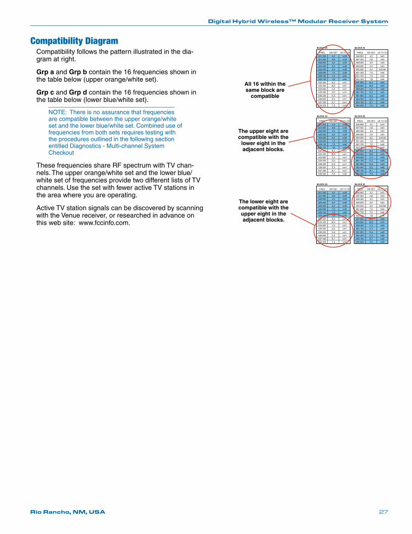
Compatibility DiagramCompatibility follows the pattern illustrated in the dia-gram at right.
Grp a and Grp b contain the 16 frequencies shown in thetablebelow(upperorange/whiteset).
Grp c and Grp d contain the 16 frequencies shown in thetablebelow(lowerblue/whiteset).
NOTE: There is no assurance that frequencies arecompatiblebetweentheupperorange/whitesetandthelowerblue/whiteset.Combineduseoffrequencies from both sets requires testing with the procedures outlined in the following section entitled Diagnostics - Multi-channel System Checkout
These frequencies share RF spectrum with TV chan-nels.Theupperorange/whitesetandthelowerblue/white set of frequencies provide two different lists of TV channels. Use the set with fewer active TV stations in the area where you are operating.
Active TV station signals can be discovered by scanning with the Venue receiver, or researched in advance on this web site: www.fccinfo.com.
BLOCK 24 BLOCK 25
FREQ SW SET US TV CH FREQ SW SET US TV CH621.300 4,5 tv39 646.900 4,5 tv43621.900 4,B tv39 647.500 4,B tv43622.800 5,4 tv39 648.400 5,4 tv43
623.400 5,A tv39 649.000 5,A tv43624.400 6,4 tv39 650.000 6,4 tv43/44625.600 7,0 tv39 651.200 7,0 tv44626.100 7,5 tv40 651.700 7,5 tv44626.700 7,B tv40 652.300 7,B tv44632.300 B,3 tv41 657.900 B,3 tv45633.300 B,D tv41 658.900 B,D tv45633.800 C,2 tv41 659.400 C,2 tv45635.500 D,3 tv41 661.100 D,3 tv45
636.200 D,A tv41 661.800 D,A tv45636.800 E,0 tv41 662.400 E,0 tv46637.500 E,7 tv41 663.100 E,7 tv46639.300 F,9 tv42 664.900 F,9 tv46
All 16 within the same block are
compatible
BLOCK 24 BLOCK 25
FREQ SW SET US TV CH FREQ SW SET US TV CH621.300 4,5 tv39 646.900 4,5 tv43621.900 4,B tv39 647.500 4,B tv43622.800 5,4 tv39 648.400 5,4 tv43
623.400 5,A tv39 649.000 5,A tv43624.400 6,4 tv39 650.000 6,4 tv43/44625.600 7,0 tv39 651.200 7,0 tv44626.100 7,5 tv40 651.700 7,5 tv44626.700 7,B tv40 652.300 7,B tv44632.300 B,3 tv41 657.900 B,3 tv45633.300 B,D tv41 658.900 B,D tv45633.800 C,2 tv41 659.400 C,2 tv45635.500 D,3 tv41 661.100 D,3 tv45
636.200 D,A tv41 661.800 D,A tv45636.800 E,0 tv41 662.400 E,0 tv46637.500 E,7 tv41 663.100 E,7 tv46639.300 F,9 tv42 664.900 F,9 tv46
The upper eight are compatible with the
lower eight in the adjacent blocks.
The lower eight are compatible with the upper eight in the adjacent blocks.

Venue Wideband Receiver
LECTROSONICS, INC.28
DiagnosticsMulti-channel System Checkout
Interference can result from a wide variety of sources including TV station signals, other wireless equipment in use nearby, or from intermodulation within a multi-channel wireless system itself. Regardless of how the frequencies were coordinated, a final checkout proce-dure is always a good idea.
Scanning with the RF spectrum analyzer built into the Venue system will identify external RF signals, but it does not address the compatibility of the selected frequencies.
The pre-coordinated frequencies on the chart on the previous pages address in-system intermodulation, but obviously cannot take into account RF signals from external sources that may be present in the location where the system will be operating.
In some cases, you can run the scanner to find clear TV channels, then find enough pre-coordinated frequencies in the tuning groups (Grp a through Grp d) to operate on the clear TV channels. Even so, it is still a good idea to go through the check out procedure because you can encounter interference from other wireless, IFB and intercom systems when you get to the production or installation site.
1. Set up the system for testing. Place antennas in the position in which they will be used and connect to the receivers. Place transmit-ters about 3 to 5 feet apart, about 25 to 30 feet from the receiver antennas. If possible, have all other equipment on the set, stage or location turned on as well, especially any mixing or recording equip-ment that will be used with the wireless system.
2. Set all receivers on clear channels. Turn on all receivers, but leave the transmitters off. Observe at the RF signal strength indicator for each receiver module. If a signal is present, change the frequency to a clear channel where no signal is indicated. If a completely clear channel cannot be found, select the frequency with the lowest RF level indication. Once all receiver modules are on clear channels, go to step 3.
3. Turn each transmitter on one at a time. Start with all transmitters turned off. As you turn on each one, look at the matching receiver to verify a strong RF signal is received. Then, look at the other receivers and see if one of them is also picking up the signal. Only the matching receiver should indi-cate a signal. Change frequencies on either system slightly until all channels pass this test, then check again to see that all channels are still clear as done in step 2.
4. Turn each transmitter off one at a time. With all transmitters and receivers turned on, turn each transmitter off one at a time, in turn, and look at the RF level indicator on the matching receiver module. The RF level should disappear or drop to a very low level. If it does not, change frequency on that receiver and transmitter and try it again. When a clear frequency is found, turn the transmitter on and move on to the next channel.
IMPORTANT: Any time a frequency is changed on any of the systems in use, you must start at the beginning and go through this procedure again for all systems. With a little practice, you will be able to do this quickly and save yourself some “multi-channel grief.”
Pilot Tone BypassSome wireless equipment uses a supersonic “pilot tone” to control the squelch (audio mute) of a receiver module to keep it silent until a valid signal is received. When a signal with the correct pilot tone is received, the squelch opens and audio is delivered to the output. Pilot tone squelch control also eliminates transients (clicks and pops) when transmitters are turned on and off. Pilot tone is supported in the Digital Hybrid compatibility modes for those systems that use it.
Pilot tone control can be bypassed as a diagnostic tool. Bypass opens the audio output of the receiver uncondi-tionally, allowing you to listen to any signals entering the receiver to help identify their source. Pilot tone bypass will also allow you to use a transmitter that has a defec-tive pilot tone circuit.
CAUTION: When pilot tone is bypassed and the transmitter is turned off, excessive noise will be present. Turn the audio level down before bypassing pilot tone.
Navigate to the PilotBP setup screen.
Select the receiver module with the Receiver Select ButtonandrotatetheMENU/SELECTcontroltoselectBYPASS. In this example, the pilot tone for receiver module 1 is set to BYPASS (BYP) and the others are set to NORMAL (NOR).
Digital Hybrid Wireless™ Modular Receiver System
Rio Rancho, NM, USA 29
ALP500
ALP620
ALP650
SNA600
Includes mounting strap and hardware
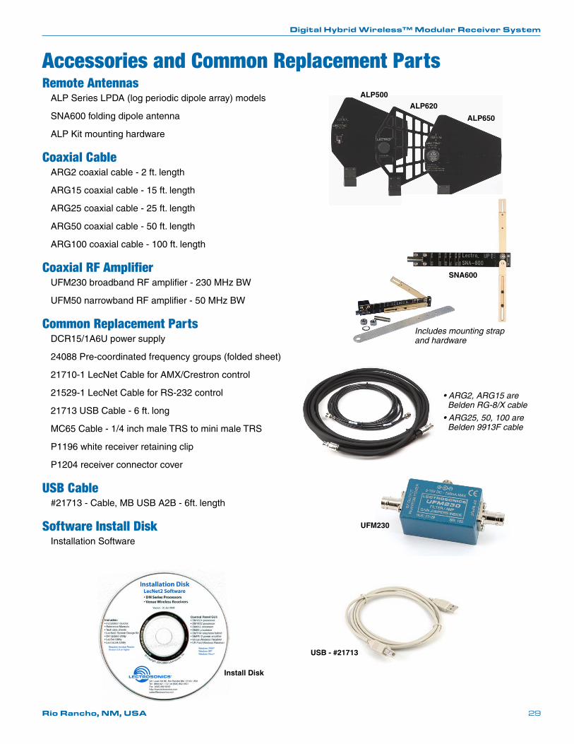
Accessories and Common Replacement PartsRemote Antennas
ALP Series LPDA (log periodic dipole array) models
SNA600 folding dipole antenna
ALP Kit mounting hardware
Coaxial CableARG2 coaxial cable - 2 ft. length
ARG15 coaxial cable - 15 ft. length
ARG25 coaxial cable - 25 ft. length
ARG50 coaxial cable - 50 ft. length
ARG100 coaxial cable - 100 ft. length
Coaxial RF AmplifierUFM230 broadband RF amplifier - 230 MHz BW
UFM50 narrowband RF amplifier - 50 MHz BW
Common Replacement PartsDCR15/1A6Upowersupply
24088 Pre-coordinated frequency groups (folded sheet)
21710-1LecNetCableforAMX/Crestroncontrol
21529-1 LecNet Cable for RS-232 control
21713 USB Cable - 6 ft. long
MC65Cable-1/4inchmaleTRStominimaleTRS
P1196 white receiver retaining clip
P1204 receiver connector cover
USB Cable#21713 - Cable, MB USB A2B - 6ft. length
Software Install DiskInstallation Software
• ARG2, ARG15 are Belden RG-8/X cable
• ARG25, 50, 100 are Belden 9913F cable
UFM230
USB - #21713
Install Disk

Venue Wideband Receiver
LECTROSONICS, INC.30
Service and RepairIf your system malfunctions, you should attempt to correct or isolate the trouble before concluding that the equipment needs repair. Make sure you have followed the setup procedure and operating instructions. Check the interconnecting cables and then go through the TROUBLESHOOTING section in this manual.
We strongly recommend that you do not try to repair the equipment yourself and do not have the local repair shop at-tempt anything other than the simplest repair. If the repair is more complicated than a broken wire or loose connection, send the unit to the factory for repair and service. Don’t attempt to adjust any controls inside the units. Once set at the factory, the various controls and trimmers do not drift with age or vibration and never require readjustment. There are no adjustments inside that will make a malfunctioning unit start working.
LECTROSONICS’ Service Department is equipped and staffed to quickly repair your equipment. In warranty repairs are made at no charge in accordance with the terms of the warranty. Out-of-warranty repairs are charged at a modest flat rate plus parts and shipping. Since it takes almost as much time and effort to determine what is wrong as it does to make the repair, there is a charge for an exact quotation. We will be happy to quote approximate charges by phone for out-of-warranty repairs.
Returning Units for RepairFor timely service, please follow the steps below:
A. DO NOT return equipment to the factory for repair without first contacting us by letter or by phone. We need to know the nature of the problem, the model number and the serial number of the equipment. We also need a phone number where you can be reached 8 A.M. to 4 P.M. (U.S. Mountain Standard Time).
B. After receiving your request, we will issue you a return authorization number (R.A.). This number will help speed your repair through our receiving and repair departments. The return authorization number must be clearly shown on the outside of the shipping container.
C. Pack the equipment carefully and ship to us, shipping costs prepaid. If necessary, we can provide you with the proper packing materials. UPS is usually the best way to ship the units. Heavy units should be “double-boxed” for safe transport.
D. We also strongly recommend that you insure the equipment, since we cannot be responsible for loss of or dam-age to equipment that you ship. Of course, we insure the equipment when we ship it back to you.
Mailing address: Shipping address: Telephone: Lectrosonics, Inc. Lectrosonics, Inc. (505) 892-4501 PO Box 15900 581 Laser Rd. (800) 821-1121 Toll-free Rio Rancho, NM 87174 Rio Rancho, NM 87124 (505) 892-6243 Fax USA USA
Web: E-mail (general): E-mail (service): www.lectrosonics.com [email protected] [email protected]

Digital Hybrid Wireless™ Modular Receiver System
Rio Rancho, NM, USA 31

24 December 2012
581 Laser Road NE • Rio Rancho, NM 87124 USA • www.lectrosonics.com(505) 892-4501 • (800) 821-1121 • fax (505) 892-6243 • [email protected]
LIMITED ONE YEAR WARRANTYThe equipment is warranted for one year from date of purchase against defects in materials or workmanship provided it was purchased from an authorized dealer. This warranty does not cover equipment which has been abused or damaged by careless handling or shipping. This warranty does not apply to used or demonstrator equipment.
Should any defect develop, Lectrosonics, Inc. will, at our option, repair or replace any defective parts without charge for either parts or labor. If Lectrosonics, Inc. cannot correct the defect in your equipment, it will be replaced at no charge with a similar new item. Lectrosonics, Inc. will pay for the cost of returning your equipment to you.
This warranty applies only to items returned to Lectrosonics, Inc. or an authorized dealer, shipping costs prepaid, within one year from the date of purchase.
This Limited Warranty is governed by the laws of the State of New Mexico. It states the entire liablility of Lectrosonics Inc. and the entire remedy of the purchaser for any breach of warranty as outlined above. NEITHER LECTROSONICS, INC. NOR ANYONE INVOLVED IN THE PRODUCTION OR DELIVERY OF THE EQUIPMENT SHALL BE LIABLE FOR ANY INDIRECT, SPECIAL, PUNITIVE, CONSEQUENTIAL, OR INCIDENTAL DAMAGES ARISING OUT OF THE USE OR INABILITY TO USE THIS EQUIPMENT EVEN IF LECTROSONICS, INC. HAS BEEN ADVISED OF THE POSSIBILITY OF SUCH DAMAGES. IN NO EVENT SHALL THE LIABILITY OF LECTROSONICS, INC. EXCEED THE PURCHASE PRICE OF ANY DEFECTIVE EQUIPMENT.
This warranty gives you specific legal rights. You may have additional legal rights which vary from state to state.