oTVC - DTIC · d. cv, cvn, cg, cgn classes (other than above)-an/src-16 transceiver (link...
49
AD-A273 995 Technical Document 2575 September 1993 Shipboard Implementation and Concept of Operations for Automatic Link Establishment 1. C. Olson oTVC L. M. Almazan ... S... " -Y Z3 I.••• Approved for public release; distribution is unlimited, 93-30846 I12 211118 lII11•ll •86111lJ ,
Transcript of oTVC - DTIC · d. cv, cvn, cg, cgn classes (other than above)-an/src-16 transceiver (link...

AD-A273 995
Technical Document 2575September 1993
ShipboardImplementationand Concept ofOperations forAutomatic LinkEstablishment
1. C. Olson oTVCL. M. Almazan ...
S... " -Y Z3 I.•••
Approved for public release; distribution is unlimited,
93-30846I12 211118 lII11•ll •86111lJ ,

Technical Document 2575September 1993
Shipboard Implementation andConcept of Operations for Automatic
Link Establishment
Accesion For
I. C. Olson NTIS CRA&I
L. M. Almazan DTIC TABU-anno:,mced ElJusti .22toio
By
t / v~ .-.!:•, .. C,• ;3
DT Ic QUAv.r I ,orJlDi-t • o: •
,J UL!YM1;27P

NAVAL COMMAND, CONTROL ANDOCEAN SURVEILLANCE CENTER
RDT&E DIVISIONSan Diego, California 92152-5001
K. E. EVANS, CAFlT USN R. T. SHEARERCommanding Officer Executive Director
ADMINISTRATIVE INFORMATION
This task was carried out by personnel in the Communications Technology Branch(Code 824) of the Naval Command, Control and Ocean Surveillance Center(NCCOSC), Research, Development, Test and Evaluation Division (RD&TE Division).Sponsorship was provided by the Space and Naval Warfare Systems Command, underprogram element OMN, accession number ICCG9800.
Released by Under authority ofJ. B. Rhode, Head R. J. Kochanski, HeadCommunication Technology Communications Systemsand Systems Branch Engineering and Integration
Division
PK

CONTENTS
1.0 BACKGROUND ............................................... 1
2.0 SC O PE ....................................................... 1
3.0 PRESENT SHIPBOARD EQUIPMENT SUITES ..................... 2
4.0 HIGH-FREQUENCY CIRCUITS ................................. 5
5.0 SYSTEM IMPLEMENTATION ................................... 6
5.1 OPTION 1: AUTOMATIC ALE TRANSCEIVER SUBSYSTEM .. 7
5.2 OPTION 2: ALE MODEM/CONTROLLER ................... 8
5.3 OPTION 3: BROADBAND RECEIVING SUBSYSTEM ......... 9
5.4 OPTION 4: BROADBAND SYSTEM ........................ 11
5.5 QUANTITY OF ALEM/CS ................................ 11
6.0 CONCEPT OF OPERATIONS (CONOPS) .......................... 13
6.1 OPERATION RULES FOR ALE ............................ 13
6.2 CONOPS PER OPTION ................................... 13
6.2.1 Option 1: Automatic ALE Transceiver .................. 13
6.2.2 Option 2: ALE Modem/Controller ..................... 13
6.2.3 Option 3: Broadband Receiving Subsystem .............. 14
6.2.4 Option 4: Broadband System .......................... 14
6.3 FREQUENCY MANAGEMENT WITH ALE .................. 14
7.0 SYSTEM ENGINEERING ANALYSIS ............................. 15
7.1 METHODOLOGY ....................................... 15
7.2 RESULTS ............................................... 15
8.0 CONCLUSIONS AND RECOMMENDATIONS ...................... 16
9.0 REFERENCES ................................................ 17
FIGURES
1. Narrowband HF architecture ........................................ 4
2. Broadband HF architecture .......................................... 4
3. Future role of HF services .......................................... 6
4. Option 1: automatic ALE transceiver .................................. 7
5. Option 2: ALE modem/controller ..................................... 8
6. Option 3A: Broadband receiving subsystem ............................ 9
7. Option 3B: Broadband receiving subsystem ............................ 10
8. Option 3C: Broadband receiving subsystem ............................ 10
9. Option 3D: Broadband receiving subsystem ............................ 11
10. Option 4: Broadband system ........................................ 12
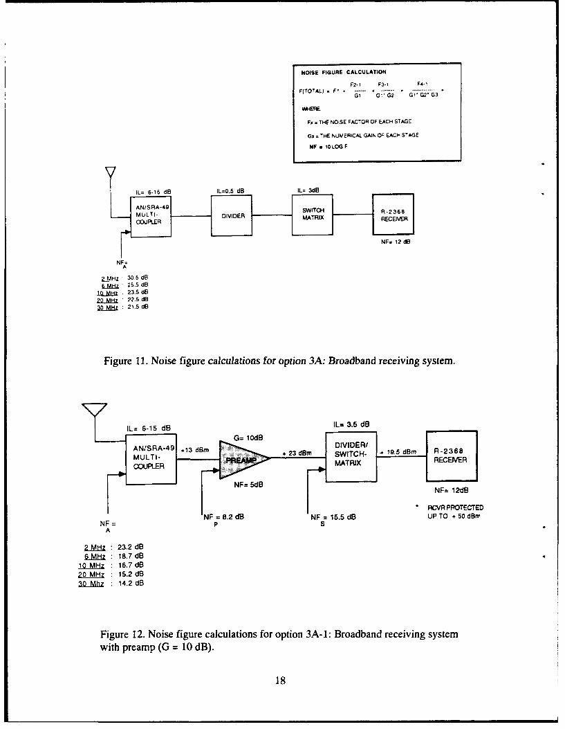
11. Noise figure calculations for option 3A: Broadband receiving system ........ 18
12. Noise figure calculations for option 3A-1: Broadband receiving systemwith preamp (G = 10 dB) ........................................... 18
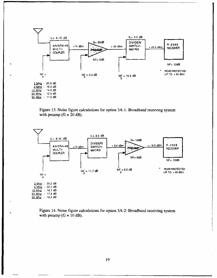
13. Noise figure calculations for option 3A-1: Broadband receiving systemwith preamp (G = 20 dB) ........................................... 19
14. Noise figure calculations for option 3A-2: Broadband receiving systemwith preamp (G = 10 dB) ........................................... 19
15. Noise figure calculations for option 3A-2: Broadband receiving system
with preamp (G = 20 dB) ........................................... 20
16. Option 3A noise figures with preamp gain = 10 dB ....................... 20
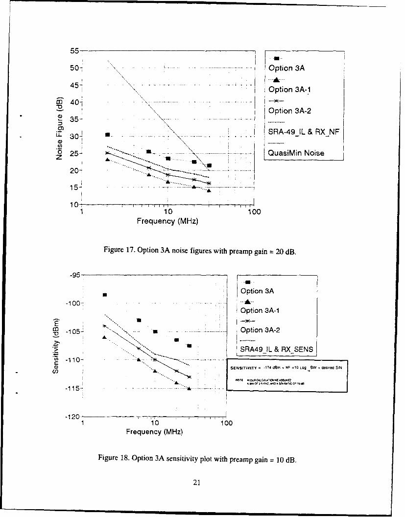
17. Option 3A noise figures with preamp gain = 20 dB ....................... 21
18. Option 3A sensitivity plot with preamp gain = 10 dB ..................... 21
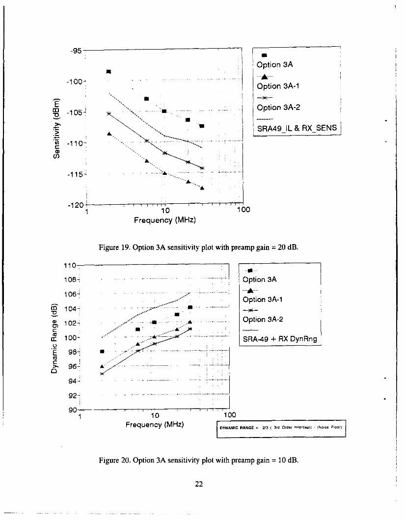
19. Option 3A sensitivity plot with preamp gain = 20 dB ..................... 22
20. Option 3A sensitivity plot with preamp gain = 10 dB ..................... 22
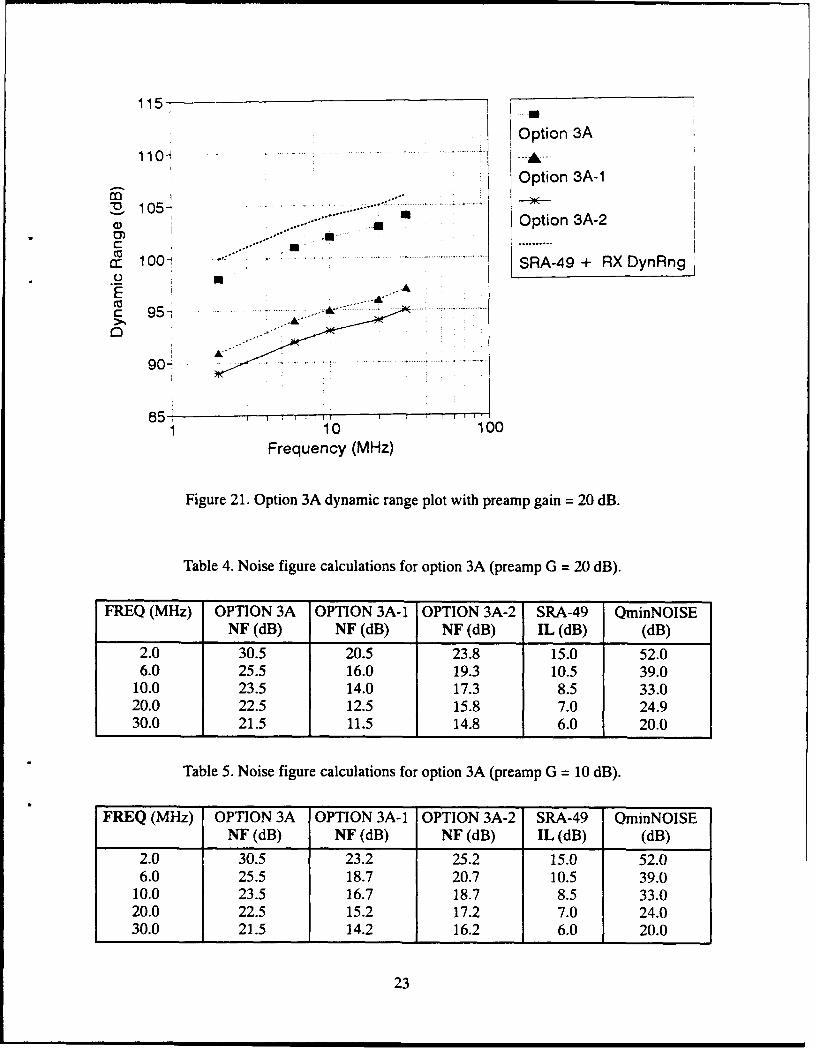
21. Option 3A dynamic range plot with preamp gain = 20 dB ................. 23
22. Noise figure calculations for option 3B: Broadband receiving system ........ 25
23. Noise figure calculations for option 3B-1: Broadband receiving systemwith preamp (G = 10 dB) ........................................... 25
24. Noise figure calculations for option 3B-I: Broadband receivingsystem with preamp (G = 20 dB) ..................................... 26
25. Noise figure calculations for option 3B-2: Broadband receivingsystem with preamp (G = 10 dB) ..................................... 26
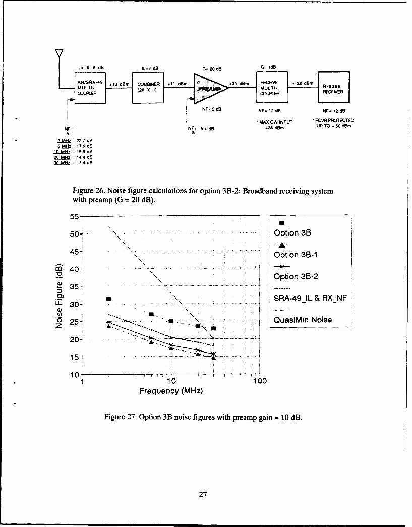
26. Noise figure calculations for option 3B-2: Broadband receivingsystem with preamp (G = 20 dB) ..................................... 27
ii
27. Option 3B noise figures with preamp gain = 10 dB ....................... 27
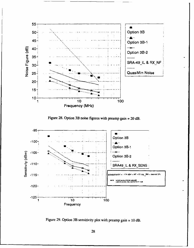
28. Option 3B noise figures with preamp gain = 20 dB ....................... 28
29. Option 3B sensitivity plot with preamp gain = 10 dB ..................... 28
30. Option 3B sensitivity plot with preamp gain = 20 dB ..................... 29
31. Option 3B dynamic range plot with preamp gain = 10 dB .................. 29
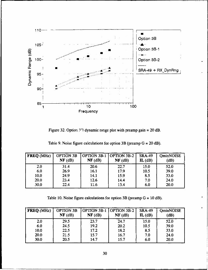
32. Option 3B dynamic range plot with preamp gain = 20 dB .................. 30
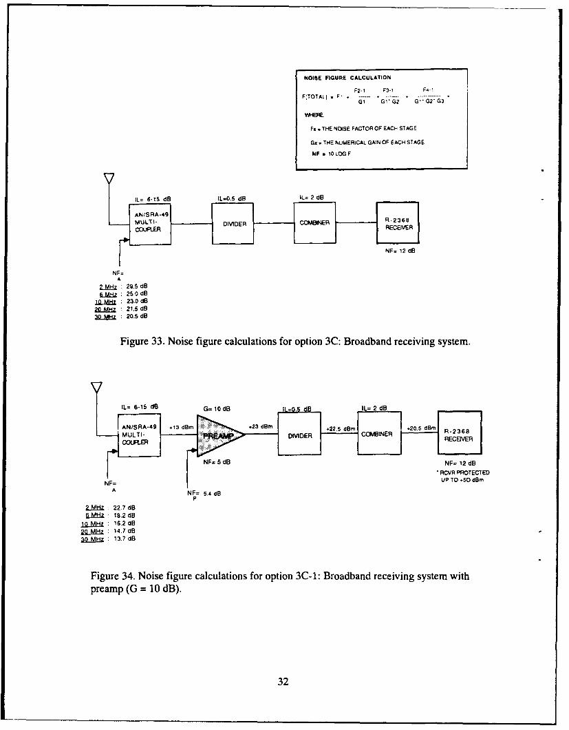
33. Noise figure calculations for option 3C: Broadband receiving system ........ 32
34. Noise figure calculations for option 3C-1: Broadband receivingsystem with preamp (G = 10 dB) ..................................... 32
35. Noise figure calculations for option 3C-1: Broadband receivingsystem with preamp (G = 20 dB) ..................................... 33
36. Noise figure calculations for option 3C-1: Broadband receivingsystem with preamp (G = 10 dB) ..................................... 33
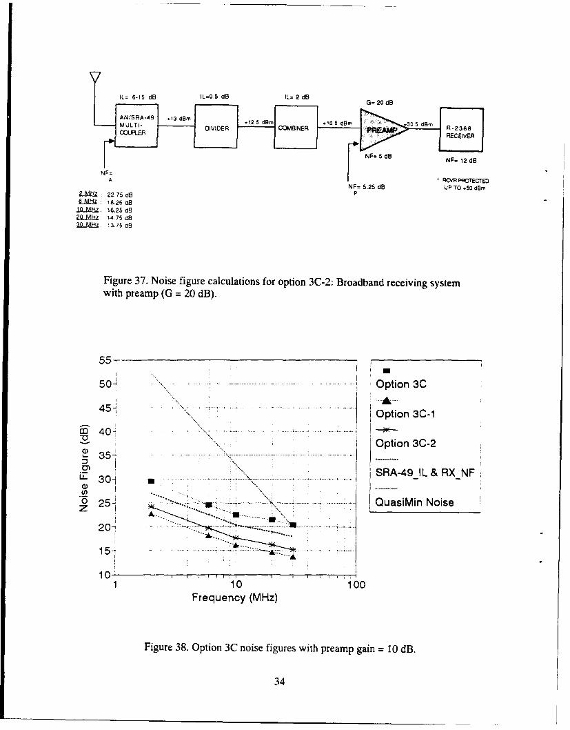
37. Noise figure calculations for option 3C-2: Broadband receivingsystem with preamp (G = 20 dB) ..................................... 34
38. Option 3C noise figures with preamp gain = 10 dB ....................... 34
39. Option 3C noise figures with preamp gain = 20 dB ....................... 35
40. Option 3C sensitivity plot with preamp gain = 10 dB ..................... 35
41. Option 3C sensitivity plot with preamp gain = 20 dB ..................... 36
42. Option 3C dynamic range plot with preamp gain = 10 dB .................. 36
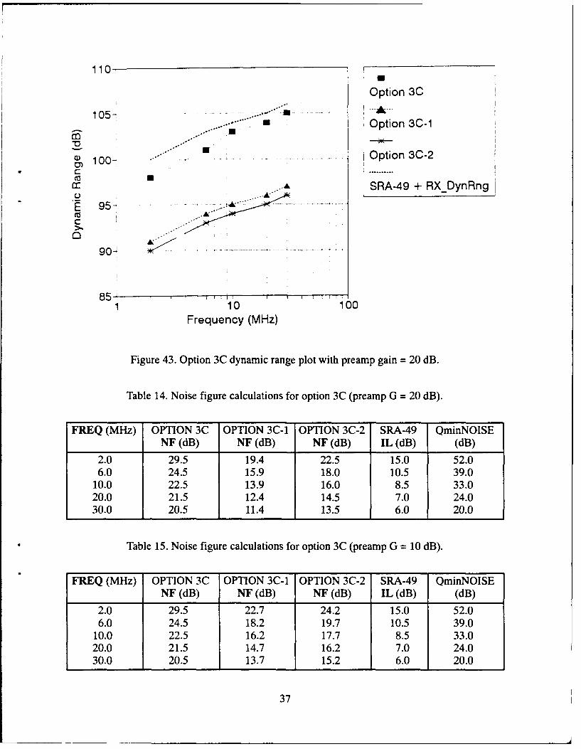
43. Option 3C dynamic range plot with preamp gain = 20 dB .................. 37
TABLES
1. Shipboard HF RF equipment suites ................................... 2
2. Shipboard HF circuit configurations .................................. 5
3. Operational rules for ALE .......................................... 12
4. Noise figure calculations for option 3A (preamp G = 20 dB) ............... 23
5. Noise figure calculations for option 3A (preamp G = 10 dB) ............... 23
6. Option 3A-1 system tradeoff considerations ............................ 24
7. Option 3A-2 system tradeoff considerations ............................ 24
iii

8. Option 3A cost comparisons ......................................... 24
9. Noise figure calculations for option 3B (preamp G = 20 dB) ............... 30
10. Noise figure calculations for option 3B (preamp G = 10 dB) ............... 30
11. Option 3B-1 system tradeoff considerations ............................ 31
12. Option 3B-2 system tradeoff considerations ............................ 31
13. Option 3B cost comparisons ......................................... 31
14. Noise figure calculations for option 3C (preamp G = 20 dB) ............... 37
15. Noise figure calculations for option 3C (preamp G = 10 dB) ............... 37
16. Option 3C-1 system tradeoff considerations ............................ 38
17. Option 3C-2 system tradeoff considerations ............................ 38
18. Option 3C cost comparisons ......................................... 38
19. Components specifications/costs ..................................... 39
iv
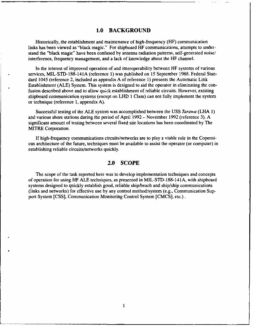
1.0 BACKGROUND
Historically, the establishment and maintenance of high-frequency (HF) communicationlinks has been viewed as "black magic." For shipboard HF communications, attempts to under-stand the "black magic" have been confused by antenna radiation patterns, self-generated noise/interference, frequency management, and a lack of knowledge about the HF channel.
In the interest of improved operation of and interoperability between HF systems of variousservices, MIL-STD-188-141A (reference 1) was published on 15 September 1988. Federal Stan-dard 1045 (reference 2, included as appendix A of reference 1) presents the Automatic LinkEstablishment (ALE) System. This system is designed to aid the operator in eliminating the con-fusion described above and to allow quick establishment of reliable circuits. However, existingshipboard communication systems (except on LHD 1 Class) can not fully implement the systemor technique (reference 1, appendix A).
Successful testing of the ALE system was accomplished between the USS Tarawa (LHA 1)and various shore stations during the period of April 1992 - November 1992 (reference 3). Asignificant amount of testing between several fixed site locations has been coordinated by TheMITRE Corporation.
If high-frequency communications circuits/networks are to play a viable role in the Coperni-cus architecture of the future, techniques must be available to assist the operator (or computer) inestablishing reliable circuits/networks quickly.
2.0 SCOPE
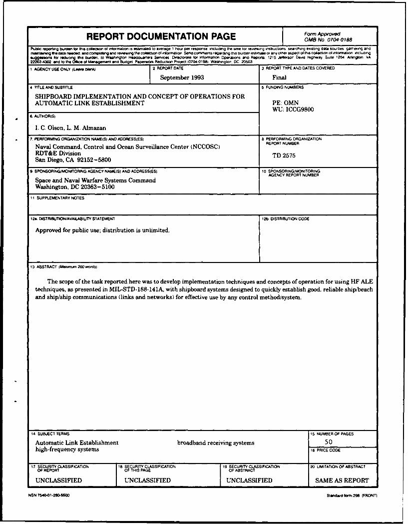
The scope of the task reported here was to develop implementation techniques and conceptsof operation for using HF ALE techniques, as presented in MIL-STD-188-141A, with shipboardsystems designed to quickly establish good, reliable ship/beach and ship/ship communications(links and networks) for effective use by any control method/system (e.g., Communication Sup-port System [CSS], Communication Monitoring Control System [CMCS], etc.).
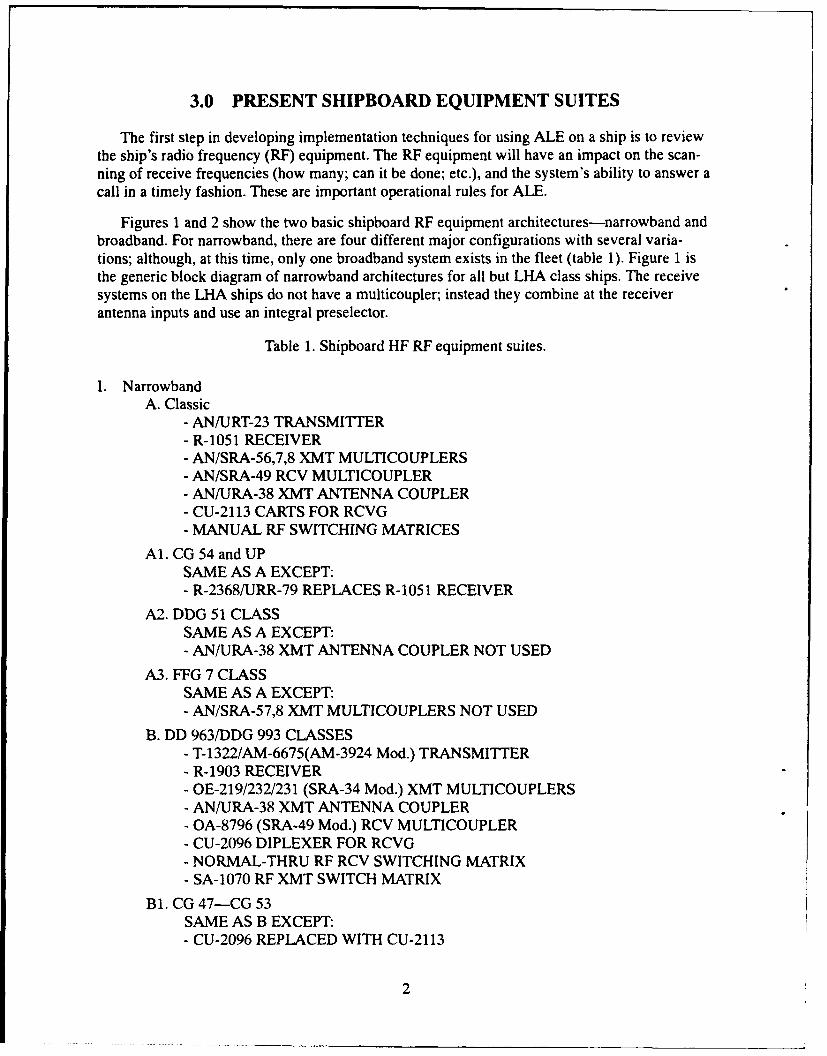
3.0 PRESENT SHIPBOARD EQUIPMENT SUITES
The first step in developing implementation techniques for using ALE on a ship is to reviewthe ship's radio frequency (RF) equipment. The RF equipment will have an impact on the scan-ning of receive frequencies (how many; can it be done; etc.), and the system's ability to answer acall in a timely fashion. These are important operational rules for ALE.
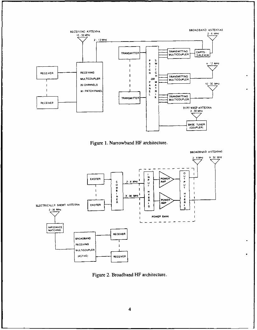
Figures 1 and 2 show the two basic shipboard RF equipment architectures-narrowband andbroadband. For narrowband, there are four different major configurations with several varia-tions; although, at this time, only one broadband system exists in the fleet (table 1). Figure 1 isthe generic block diagram of narrowband architectures for all but LHA class ships. The receivesystems on the LHA ships do not have a multicoupler; instead they combine at the receiverantenna inputs and use an integral preselector.
Table 1. Shipboard HF RF equipment suites.
I. NarrowbandA. Classic
- AN/URT-23 TRANSMITTER- R-1051 RECEIVER- AN/SRA-56,7,8 XMT MULTICOUPLERS- AN/SRA-49 RCV MULTICOUPLER- AN/URA-38 XMT ANTENNA COUPLER- CU-2113 CARTS FOR RCVG- MANUAL RF SWITCHING MATRICES
Al. CG 54 and UPSAME AS A EXCEPT:- R-2368/URR-79 REPLACES R-1051 RECEIVER
A2. DDG 51 CLASSSAME AS A EXCEPT:- AN/URA-38 XMT ANTENNA COUPLER NOT USED
A3. FFG 7 CLASSSAME AS A EXCEPT:- AN/SRA-57,8 XMT MULTICOUPLERS NOT USED
B. DD 963/DDG 993 CLASSES- T-1322/AM-6675(AM-3924 Mod.) TRANSMITTER- R-1903 RECEIVER- OE-219/232/231 (SRA-34 Mod.) XMT MULTICOUPLERS- AN/URA-38 XMT ANTENNA COUPLER- OA-8796 (SRA-49 Mod.) RCV MULTICOUPLER
- CU-2096 DIPLEXER FOR RCVG- NORMAL-THRU RF RCV SWITCHING MATRIX- SA-1070 RF XMT SWITCH MATRIX
Bi. CG 47-CG 53SAME AS B EXCEPT:- CU-2096 REPLACED WITH CU-2113
2
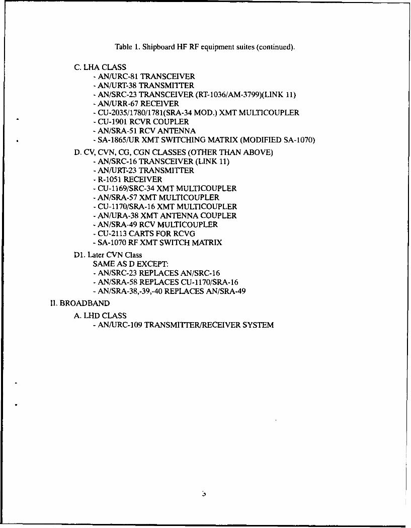
Table 1. Shipboard HF RF equipment suites (continued).
C. LHA CLASS- AN/URC-81 TRANSCEIVER- AN/URT-38 TRANSMI"ITER- AN/SRC-23 TRANSCEIVER (RT-1036/AM-3799)(LINK 11)- AN/URR-67 RECEIVER- CU-2035/1780/1781(SRA-34 MOD.) XMT MULTICOUPLER- CU-1901 RCVR COUPLER- AN/SRA-51 RCV ANTENNA- SA-1865/UR XMT SWITCHING MATRIX (MODIFIED SA-1070)
D. CV, CVN, CG, CGN CLASSES (OTHER THAN ABOVE)- AN/SRC-16 TRANSCEIVER (LINK 11)- AN/URT-23 TRANSMITTI7ER- R-1051 RECEIVER- CU-1169/SRC-34 XMT MULTICOUPLER- AN/SRA-57 XMT MULTICOUPLER- CU-1170/SRA-16 XMT MULTICOUPLER- AN/URA-38 XMT ANTENNA COUPLER- AN/SRA-49 RCV MULTICOUPLER- CU-2113 CARTS FOR RCVG- SA-1070 RF XMT SWITCH MATRIX
D1. Later CVN ClassSAME AS D EXCEPT:- AN/SRC-23 REPLACES AN/SRC-16- AN/SRA-58 REPLACES CU-1170/SRA-16- AN/SRA-38,-39,-40 REPLACES AN/SRA-49
II. BROADBAND
A. LHD CLASS- AN/URC-109 TRANSMITTERIRECEIVER SYSTEM
3
RECEIVING ANTENNA BROADBAND &NTENNAS
10 30 0,4142 2 6 fJHZ
2 12 MHz
TRANSMITTER TRANSMIT-TING CARTS IMULTICOUPLER DIPLEXER
P sA W 4 !2 MHzT IC T
RECEIVE RECEIVING H CH TRANSMITTING
MULTICOUPLER oil MULTICOUPLERP M 4ýý
20 CHANNELS A A 0 - 30 MHz
N Tw t PATCH PANEL E R
TRANSMITTER x TRANSMITTINGMULTICOUPLER
RECE IVER H 4 tt 35 Fr WHT ANTENNA
2 30 MHz
v
BIAS EUT LIN E RCO 'L
(COUPLER)
Figure 1. Narrowband HF architecture.
BROADBAND ANTENNAS
2, X MHz X 3C MHZ
N UEXCITER P WeR T
C 2-x MHz U AMýP P00 T UM TB HI y HN X 30 MHz
E BA POWER
ELECTRICALI-Y SHORT ANTENNA EE.CITER I >AMP R
2 - 30 MHz
POWER BANK
L - - - - - - - - - - - -
IMPEDANCEMATCHING
RECEIVER
BROADBAND
L RECEIVING I
MULTICOUPLER I -
(ACTIVE) RECEIVER
Figure 2. Broadband HF architecture.
4
4.0 HIGH-FREQUENCY CIRCUITS
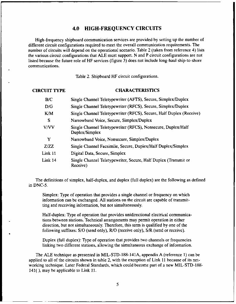
High-frequency shipboard communication services are provided by setting up the number ofdifferent circuit configurations required to meet the overall communication requirements. Thenumber of circuits will depend on the operational scenario. Table 2 (taken from reference 4) liststhe various circuit configurations that ALE must support. N and P circuit configurations are notlisted because the future role of HF services (figure 3) does not include long-haul ship-to-shorecommunications.
Table 2. Shipboard HF circuit configurations.
CIRCUIT TYPE CHARACTERISTICS
B/C Single Channel Teletypewriter (AFTS), Secure, Simplex/Duplex
D/G Single Channel Teletypewriter (RFCS), Secure, Simplex/Duplex
K/M Single Channel Teletypewriter (RFCS), Secure, Half Duplex (Receive)
S Narrowband Voice, Secure, Simplex/Duplex
V/VV Single Channel Teletypewriter (RFCS), Nonsecure, Duplex/HalfDuplex/Simplex
Y Narrowband Voice, Nonsecure, Simplex/Duplex
Z/ZZ Single Channel Facsimile, Secure, Duplex/Half Duplex/Simplex
Link 11 Digital Data, Secure, Simplex
Link 14 Single Channel Teletypewriter, Secure, Half Duplex (Transmit orReceive)
The definitions of simplex, half-duplex, and duplex (full duplex) are the following as definedin DNC-5.
Simplex: Type of operation that provides a single channel or frequency on whichinformation can be exchanged. All stations on the circuit are capable of transmit-ting and receiving information, but not simultaneously.
Half-duplex: Type of operation that provides unidirectional electrical communica-tions between stations. Technical arrangements may permit operation in eitherdirection, but not simultaneously. Therefore, this term is qualified by one of thefollowing suffixes: S/O (send only), R/O (receive only), S/R (send or receive).
Duplex (full duplex): Type of operation that provides two channels or frequencieslinking two different stations, allowing the simultaneous exchange of information.
The ALE technique as presented in MIL-STD-188-141A, appendix A (reference 1) can beapplied to all of the circuits shown in table 2, with the exception of Link 11 because of its net-working technique. Later Federal Standards, which could become part of a new MIL-STD-188-141( ), may be applicable to Link 11.
5
BEACH
BATTLEGROUP I
ALLIED/COALITIONFORCES
OTHER SERVICES
BATTLEGROUP It
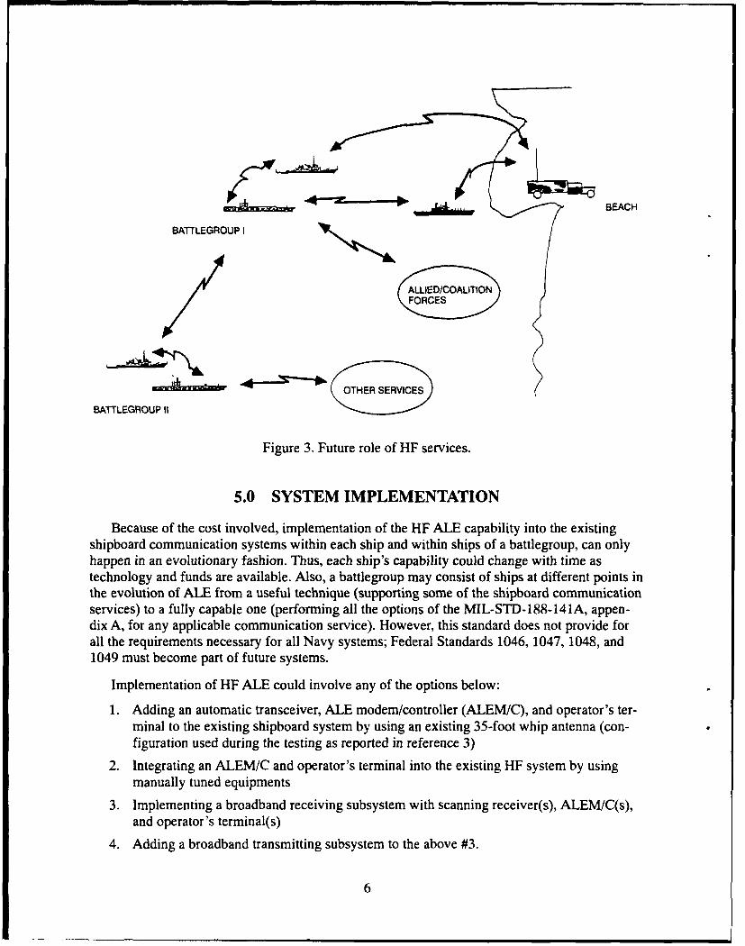
Figure 3. Future role of HF services.
5.0 SYSTEM IMPLEMENTATION
Because of the cost involved, implementation of the HF ALE capability into the existingshipboard communication systems within each ship and within ships of a battlegroup, can onlyhappen in an evolutionary fashion. Thus, each ship's capability could change with time astechnology and funds are available. Also, a battlegroup may consist of ships at different points inthe evolution of ALE from a useful technique (supporting some of the shipboard communicationservices) to a fully capable one (performing all the options of the MIL-STD-188-141A, appen-dix A, for any applicable communication service). However, this standard does not provide forall the requirements necessary for all Navy systems; Federal Standards 1046, 1047, 1048, and1049 must become part of future systems.
Implementation of HF ALE could involve any of the options below:
1. Adding an automatic transceiver, ALE modem/controller (ALEM/C), and operator's ter-minal to the existing shipboard system by using an existing 35-foot whip antenna (con-figuration used during the testing as reported in reference 3)
2. Integrating an ALEM/C and operator's terminal into the existing HF system by usingmanually tuned equipments
3. Implementing a broadband receiving subsystem with scanning receiver(s), ALEM/C(s),and operator's terminal(s)
4. Adding a broadband transmitting subsystem to the above #3.
6
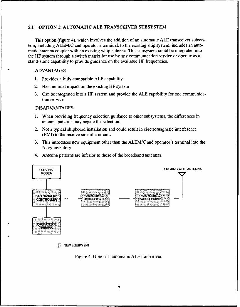
5.1 OPTION 1: AUTOMATIC ALE TRANSCEIVER SUBSYSTEM
This option (figure 4), which involves the addition of an automatic ALE transceiver subsys-tem, including ALEM/C and operator's terminal, to the existing ship system, includes an auto-matic antenna coupler with an existing whip antenna. This subsystem could be integrated intothe HF system through a switch matrix for use by any communication service or operate as astand-alone capability to provide guidance on the available HF frequencies.
ADVANTAGES
1. Provides a fully compatible ALE capability
2. Has minimal impact on the existing HF system
3. Can be integrated into a HF system and provide the ALE capability for one communica-tion service
DISADVANTAGES
1. When providing frequency selection guidance to other subsystems, the differences inantenna patterns may negate the selection.
2. Not a typical shipboard installation and could result in electromagnetic interference(EMI) to the receive side of a circuit.
3. This introduces new equipment other than the ALEM/C and operator's terminal into theNavy inventory
4. Antenna patterns are inferior to those of the broadband antennas.
EXTERNAL EXISTING WHIP ANTENNAMODEM
Q NEW EQUIPMENT
Figure 4. Option 1: automatic ALE transceiver.
7

5.2 OPTION 2: ALE MODEM/CONTROLLER
This option does not follow on from option 1 above, but is a different starting point in theevolution of ALE into the shipboard HF system. An ALEM/C and operator's terminal would beadded to any of the existing shipboard systems (figure 5). The option would be integrated suchthat it could be switched into any subsystem to provide an ALE capability for any communica-tion service. Multiple ALEM/Cs could be installed.
ADVANTAGES
1. Provides a very limited ALE capability for a particular communication service
2. Has minimal impact on existing HF system
3. Uses same antennas for ALE and communication service
4. Has minimum cost for an ALE capability
DISADVANTAGES
1. Scan sets and frequencies within a scan set are limited to one for the narrowband HF sys-tems.
2. Several possible frequencies for a communication service or services take considerabletime to evaluate.
ANTENNA SYSTEM ANTENNA SYSTEMTTRANSMITTER
TO RECEIVERS
SEXISTING SWATCH
IMODEM MATRIX
AN/SRA-49 I/
RECEIVE ..........SCOMMUNICATION
MULTICOUIPLER RECEIVER C R F0 Z
(20 CHANNELS)
0 NEW EQUIPMENT
Figure 5. Option 2: ALE modem/controller.
8

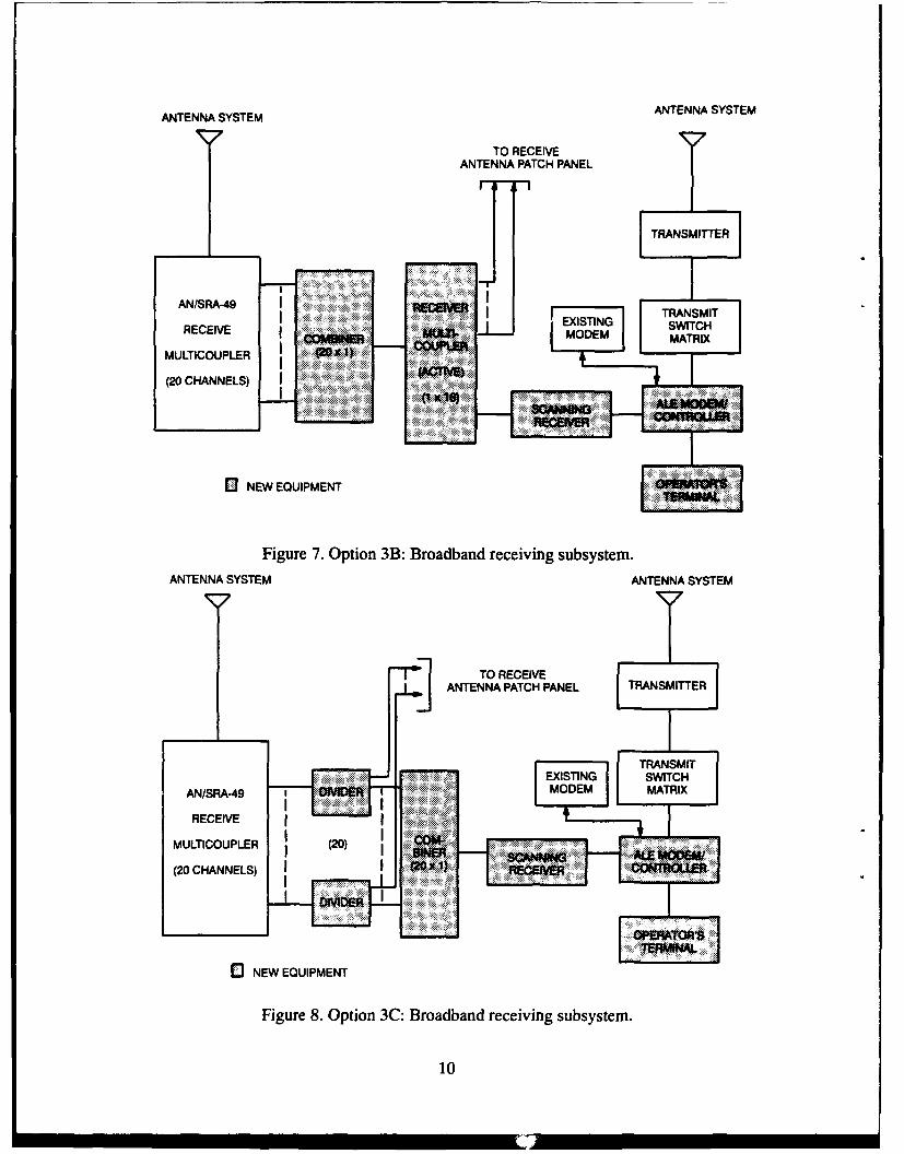
5.3 OPTION 3: BROADBAND RECEIVING SUBSYSTEM
This option could be either a starting point in evolving ALE into the fleet or could follow onfrom option 2. Implementation of this option could be accomplished in the following ways:(1) Provide access to the 20 channels of the AN/SRA-49 receiving multicoupler for a scanningreceiver while providing signals to the normal communication receivers; (2) Place a broadbandreceiving subsystem (like that used by the AN/URC-109) on the ships in place of, or in additionto, the existing receiving subsystem. The ALEM/C and operator's terminal would interface withthe scanning receiver and a manual transmit subsystem. Various transmit subsystems could beconnected to the ALEM/C to support different communication services. Different methods ofimplementation are shown in figures 6, 7, and 8.
ADVANTAGES
1. Provides a limited compatible ALE capability for a particular communication service
2. Scans several frequencies listening for calls
3. Uses same antennas for ALE and communication service4. Eliminates any frequency constraints when using second option 3D (figure 9)
DISADVANTAGES
1. Number and distribution of frequencies limited by the AN/SRA-49 (for options 3A, 3B,and 3C)
2. Slow response to call unless transmit subsystem is pretuned
3. Potential EMI problems with option 3D on small platforms
ANTENNA SYSTEM ANTENNA SYSTEM
]' TO RECEIVEANTENNA PATCH PANEL TRANSMITTER
SEXISTING SWITCH
OMDER MODEM MATRIX
AN/SRA-49
RECEIVE (20) SWIT,1
I () MATX A AMMODMMULTICOUPLER C
(20 CHANNELS) I OER
0 NEW EQUIPMENT
Figure 6. Option 3A: Broadband receiving subsystem.
9
ANTENNA SYSTEM ANTENNA SYSTEM
TO RECEIVEANTENNA PATCH PANEL
r-, 7'-1
TRANSMITTER
AN]SRA-ANTE RECETRANSMITEXISTING SWITCH
RECIV MODEM MATRIX
MULTICOUPLER (
(20 CHANNELS) I I
o NEW EQUIPMENT
Figure 7. Option 3B: Broadband receiving subsystem.ANTENNA SYSTEM ANTENNA SYSTEM
ANTENNA PATCH PANEL TRANSMITTER
S~TRANSMITEXISTING SWITCH
AN/SRA-49 MDMMATRIX
RECEIVE
MULTICOUPLER (20) I
(20 CHANNELS) R ......:':"R :
SNEW EQUIPMENT
Figure 8. Option 3C: Broadband receiving subsystem.
10
I I IIIMI•'

ANTENNA SYSTEMSMALL ANTENNA
OTHER RECEIVERS
TRANSMITTER
BRABN TRANSMITRECEIVE' EXISTING SWI TCHAN E N ............ ............... EI VM:•!!• • .••',:''i•! ::!l MODEM MATRIX
ANTENNA
UNITI
[3 NEW EQUIPMENT WR
Figure 9. Option 3D: Broadband receiving subsystem.
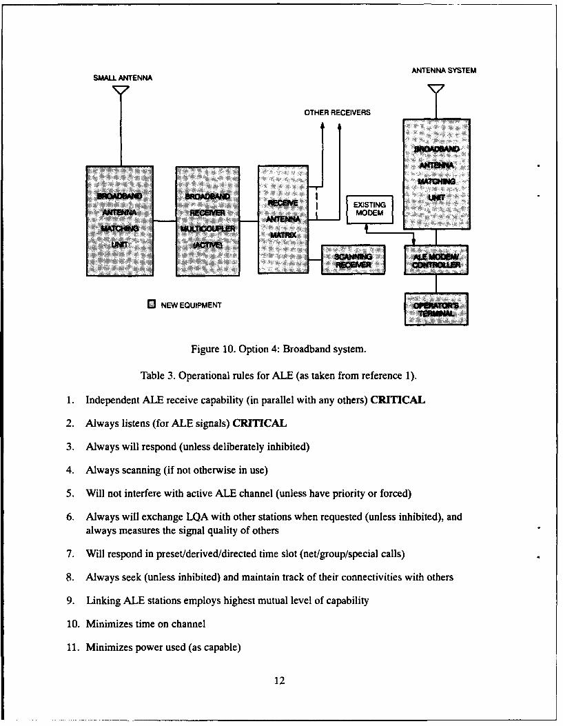
5.4 OPTION 4: BROADBAND SYSTEM
This option (figure 10) would add a broadband transmitting subsystem to option 3 above.Adding this option to option 3D (figure 9) would be preferable. This results in a fully broadbandsystem that is not constrained by any mechanically tuned devices. With the addition of anALEM/C and operator's terminal, one would have a full ALE capability limited only by theALEM/C.
ADVANTAGE
1. Fully compatible ALE capability
DISADVANTAGES
1. Expensive to do as e%,•;uLionary approach for existing ships
2. Potential for EMI problems if improperly designed or operated
5.5 QUANTITY OF ALEM/CS
The quantity of ALEM/Cs and operator's terminals per ship should be determined by thenumber of different receiving antenna subsystems used. Operational rule 1 (table 3) states that itis critical that the ALEM/C is always listening. Because of antenna pattern differences andfrequency coverage, each antenna subsystem should be covered simultaneously. Since theALEM/C does not monitor the communication service performance, there is no need to provideone for each service. Shared use is the recommended impiementation approach. One additionalALEM/C should be provided for backui-
11
ANTENNA SYSTEMSMALL ANTENNA
OTHER RECEIVERS
0RNEEIEQ IESTING
Figure 10. Option 4. Broadband system.
Table 3. Operational rules for ALE (as taken from reference 1).
1. Independent ALE receive capability (in parallel with any others) CRITICAL
2. Always listens (for ALE signals) CRITICAL
3. Always will respond (unless deliberately inhibited)
4. Always scanning (if not otherwise in use)
5. Will not interfere with active ALE channel (unless have priority or forced)
6. Always will exchange LQA with other stations when requested (unless inhibited), andalways measures the signal quality of others
7. Will respond in preset/derived/directed time slot (net/group/special calls)
8. Always seek (unless inhibited) and maintain track of their connectivities with others
9. Linking ALE stations employs highest mutual level of capability
10. Minimizes time on channel
11. Minimizes power used (as capable)
.12

6.0 CONCEPT OF OPERATIONS (CONOPS)
The CONOPS for using ALE from shipboard platforms will depend on how the technique isimplemented. Several implementation options have been presented in section 5.0. Not includedabove, but also important to the CONOPS, is switching available for the ALEM/C and othermodems. A CONOPS for each of the options will be discussed below. All of the various optionsare interoperable with each other and any other system that employs a MIL-STD-188-141Amodem/controller.
The CONOPS for ALE from shipboard platforms will be influenced by the ship's antennasystem. Because the antenna radiation patterns are not omnidirectional and are different for eachantenna, the same antenna(s) must be used for both the ALE function and the communicationservice it supports. Also, because of the antennas, the LQA tables may be valid for only shortperiods of time as the ship steams and changes course.
6.1 OPERATION RULES FOR ALE
MIL-STD-188-141A states that the ALE system shall incorporate the operational rules listedin table 3. Rule 2 is not required during temporary periods when not technically feasible (e.g.,during transmit with a transceiver or when using a common antenna with a transmitter andreceiver).
6.2 CONOPS PER OPTION
As stated previously, all of these options are interoperable with each other and any other sys-tem using a MIL-STD-188-141A modem. However, the capability will be determined by theimplementation used. All of the options, except option 2, can abide by the rules stated in table 4.
6.2.1 Option 1: Automatic ALE Transceiver
This option, as shown in figure 4, provides fully capable ALE support to a single commu-nication service. The service is dependent on the modem used. With the addition of a switchbetween the external modem and the ALEM/C, several services could be supported one at atime. Any of the features of MIL-STD-188-141A can be used with this option.
This option will not support any communication services requiring duplex circuits. Becauseof antenna pattern differences, this option can not provide reliable frequency selection guidanceto other subsystems.
The CONOPS for this option would be to select the features of the MIL-STD required tooperate the circuit needed to provide the communication service. Available frequencies woulddepend on the strategy used for frequency management. This will be discussed later in thisreport.
6.2.2 Option 2: ALE Modem/Controller
This option, as shown in figure 5, provides a very limited capability to support several com-munication services (one at a time). The service is dependent on the rest of the system. With the
13

addition of switch matrices between ALEM/C and receiver and existing modems, several ser-vices could be supported one at a time.
This option can not invoke operational rule 4 because it is limited to a fixed frequency. Itwill provide a very limited capability with regard to rules 6 through 9.
The CONOPS for this option would be selection of the service to be supported, placement ofthe ALEM/C into the system, and setup to operate on the assigned frequency. Once the circuit isestablished, the ALEM/C could be switched into another system. The ALEM/C would be usedwith systems in order of priority starting with the highest.
6.2.3 Option 3: Broadband Receiving Subsystem
This option (figures 6 through 9) provides a limited capability to support link establishmentfor one service while providing LQA information for up to 19 other communication services.Except for option 3D, the number and distribution of frequencies is limited by the manuallytuned AN/SRA-49. The response time to answer a call is determined by the time to manuallytune the transmit subsystem.
The CONOPS for this option would be either of two ways: (1) Support one communicationservice by establishing the link and then use an existing modem while providing LQA informa-tion for other services; or (2) determine LQAs for the various frequencies/circuits and providethat information to the subsystems that support the various services. The transmit subsystemwould have to be manually tuned to initiate or answer a call. Frequencies would be managed insuch a way that the frequencies with the best LQAs would be assigned to the highest priority ser-vices. More will be discussed below on this frequency management concept.
6.2.4 Option 4: Broadband System
This option (figure 10) provides a fully compatible ALE capability only limited by the par-ticular ALEM/C chosen for implementation. All of the functions required by MIL-STD-188-141A can be used with this option.
The CONOPS for this option would have the ALEM/C measure the LQAs for all the fre-quencies assigned to the ship/battlegroup and provide that information to a frequency managerwho would assign the frequencies to various services. Through interaction with the power con-trol of the transmit subsystem, the minimum power for acceptable communication could bedetermined.
6.3 FREQUENCY MANAGEMENT WITH ALE
The implementation of ALE in accordance with appendix A of MIL-STD-188-141A willallow a break from the traditional way of frequency assignment/management. Traditionally, twofrequencies are assigned to each communication service; one is the primary and the second is abackup. The performance of a frequency used for a link to provide a service is a function of timeof year, time of day, geographic location, sunspot activity, length of link, transmit power, andantenna performance. Often, very little attention is paid to these factors when assigning frequen-cies to a link.
14

By using the features of the ALE standard, frequency management can be approached differ-ently and can break from tradition. By using the sounding and LQA capability, the influence ofall the factors listed above are included for each frequency over each link. Frequency manage-ment with increased performance could be accomplished with the following steps:
a. Treat all the frequencies assigned to the platform/battlegroup as a pool.
b. Rank in order of performance all frequencies between all platforms by using LQA.
c. Rank in order of priority all communication services between platforms.
d. Assign communication services in order of priority to frequencies ordered by LQA.
e. Use the voice or data message capability of the ALEM/C to coordinate frequency assign-ments.
When a large number of frequencies/platforms are involved, it would be much more efficientto establish subsets of frequencies per platform using a prediction program such as PROPHET,IONCAP, etc. The most probable propagating frequencies would make up the subsets.
7.0 SYSTEM ENGINEERING ANALYSIS
A system engineering analysis of the various options will serve as a method to select the rec-ommended approach to implement the ALE capability into existing ship HF communication sys-tems. Option 4 provides the greatest capability for the use of ALE. However, it requires a com-pletely new HF communication system on almost all existing ships on which it would not be costeffective just to add an ALE capability. Options 1 and 2 provide a capability that is too limited tobe of much use. This leaves option 3 to be analyzed. Options 3A, 3B, and 3C appear to have thepotential to provide good ALE capability at a reasonable cost. Option 3D was not includedbecause it requires a new and potentially expensive broadband receiving subsystem.
7.1 METHODOLOGY
Considering the above, the analysis was performed on options 3A, 3B, and 3C. The analysisconsists of calculating the system noise figure, sensitivity, dynamic range, and cost. Each of theoptions were evaluated for three configurations: (1) without RF amplifier; (2) with 10-dB gainamplifier; and (3) with 20-dB gain amplifier. The data from this analysis are contained infigures 11 through 43 and tables 4 through 18. A representative set of costs for variouscomponents is contained in table 19.
7.2 RESULTS
The data were analyzed for each of the parameters listed above in the various configurations.The best system noise figure was provided by option 3C-1 for either the 10-dB or 20-dB ampli-fier configuration. The system noise figure without an amplifier is considered too high. Themaximum variation across the options with the 20-dB amplifier was 4.4 dB and with the 10-dBamplifier was 2.5 dB. The noise figures provided with the 10-dB amplifier are sufficient for
15
good receive system performance. All system noise figures with amplifiers are less than thoseprovided by the basic system (multicoupler + receiver.)
The best sensitivity using a 10-dB amplifier is provided by option 3C-1. The variation overall the various options is only 2.5 dB. The sensitivity for each option that uses an amplifierexceeds that of the basic system.
The dynamic range for the options using the 10-dB amplifier is either 95 or 96 dB at 2 MHz.This is better dynamic range than that provided by the options using the 20-dB amplifier. How-ever, it is 4 or 5 dB less dynamic range than that provided by the basic system. The reduction indynamic range seems reasonable considering the increased overall performance that is gained byusing ALE.
The amplifier option with the lowest estimated cost is option 3C-2 ($2830) followed byoption 3B-2 ($7110.) The estimated costs for the various options range from $2830 to $37,240.
A comparison of the performance of options 3B-2 and 3C-2 shows that option 3C-2 is about0.5 dB better in noise figure and sensitivity and has a $4280 lower estimated cost. However,option 3B-2 is the recommended approach because it would allow the addition of another ALEcapability without any changes and provide access by other receivers to any of the 20 frequen-cies tuned up on the AN\SRA-49 without patching or switching.
8.0 CONCLUSIONS AND RECOMMENDATIONS
The following conclusions have been reached by this study:
1. Options to implement an ALE capability are on every navy ship. The capability will be afunction of the option used.
2. All of the options presented are interoperable with each other and with any other systememploying an ALEM/C that meets MIL-STD-188-141A.
3. CONOPS will be a function of the implementation option.
4. ALE supports a new frequency management philosophy that will improve the HF systemperformance.
The recommendations are:
1. Install ALEM/Cs on every navy ship in a quantity equal to the number of differentreceiving subsystems plus one.
2. Use Option 3D where possible with Option 3B-2 as an alternative for ships with anAN/SRA-49.
3. Manage the set of HF frequencies with the new strategy presented in paragraph 6.3.
16
9.0 REFERENCES
1. MIL-STD-188-141A. "Military Standard Interoperability and Performance Standards forMedium and High-Frequency Radio Equipment," 15 September 1988.
2. Federal Standard 1045. "Telecommunications: HF Radio Automatic Link Establishment,"24 January 1990.
3. Danielson, T. A., and J. A. Ramos. "The Operational use of an Automated High-FrequencyRadio System Incorporating Automatic Link Establishment and Single-Tone Serial ModemTechnology for U.S. Navy Ship-Shore Communications," NCCOSC RDT&E Div. To bepublished.
4. NAVSHIPS 0967-301-7020. "Afloat Communication Systems Criteria Handbook," vol. II,Circuit Configurations, 1 February 1971.
17
NOISE FIGURE CALCULATION
F2-1 F3-1 F4-1F(TOTAL) . F1 * . G . . .. ..GI Gi" G2 Gl" G2" G3
W4EE
Fx THE NOISE FACTOR OF EACH STAG-E
Gx THE NUUMERICAL GAIN Oý EACH STAGE
NF . ILOGF
IL= 6-15 d8 IL=0.5 dB IL= 3d8b
AN/S RA-49 SIC
M UL T I - DIVIDER MATRIX RECEIVER
NF. 12 dB}
NF=A
2.. '_• :30.5 d86 MHz: 25.5 dB
10 MHZ ;23.5 dB20 MHz 22.5 dB30 MHz :21.5dB
Figure 11. Noise figure calculations for option 3A: Broadband receiving system.
IL= 6-15 dB IL= 3.5 dB
G= 10d13AN/SRA-49 -13 dB DIVIDER/
MULI-+ 2dB SWITCH. + 19.5 dBm R-2368COULTIRP MATRIX RECEIVER
RCVR PROTECTEDNF= 8.2 dB NF= 15.5 dB UP TO + 50 dBm
NF= p SA
2 MHz 23.2 dB
6MHz 18.7dB10MHz 16.7dB20 MHz 15.2 dB
30 Mhz 14.2 dB
Figure 12. Noise figure calculations for option 3A-1: Broadband receiving systemwith preamp (G = 10 dB).
18
IL= 6-15 dB IL= 3.5 dB
G-~l 20.5 dBIDR
AN/SRA-49 .13 dBm + 33 aBm SWITCH- R 29-2368 CEVE
M U LTI - MAT RIX 295dm RCIE
N= 5dBNF= 12dIB
RC'VR PROTECTEDNF = NF =5.5 dB3 NF =15.5 dB3 UP TO + 50 d~m
A P S
2 MHz :20.5 d86 MHz :16.0 dB
10 MHz 14.0 dB20 MHz 12.5 dB30 MI : 11.5dB
Figure 13. Noise figure calculations for option 3A-1: Broadband receiving systemwith preamp (G = 20 dB).
NIL= 3.5 1B
7 - L -5d DIVIDER/ G 0I
A N/S R A -49 -. 3 dS T H - ,-9.5 ÷~r 19.5 dB n R -23 68
M UL T I- MATRIX RCIECOUPLE-R>
I NF 5dBNF= 12dB
NF= 11.7 dB NF =8.2 dB RCVR PROTECTED
NF= S P UPTO +50dBm
A
2 MHz 25.2 dB6 MHz 20.7 dB
10 MHz 18.7dB20 MHz 17.2 dB30 Mhz 16.2 dB
Figure 14. Noise figure calculations for option 3A-2: Broadband receiving systemwith preamp (G = 10 dB).
19

IL= 6-1 dB5d NF 20.dB
NNF= S P
A
2.M~iz 23.75 dB612H 19.25 d8
10 Mtz 17.25 d820M * 15.75 dB3( M 14,75 d8
Figure 15. Noise figure calculations for option 3A-2: Broadband receiving systemwith preamp (G =20 dB).
5 5 .............
50-........ - . .. .... . Option 3A
540- -
Option 3A-2
Opio 35-2
SRA-49_IL &RXNF
... 25.. ........... QuasiMin NoiseZ A , . .......
20-'--
,5 A
101 10 100
Frequency (MHz)
Figure 16. Option 3A noise figures with preamp gain =10 dB.
20
55 I
50........... Option 3A
45 Option 3A-1M 40-'... .
Option 3A-2b- 35 - .....
3 QISRA-49_IL &RXNF
0 25-'-.* .-. QuasiMin Noise
20i A. -
1 5 -' ....................
10.II I
1 10 100Frequency (MHz)
Figure 17. Option 3A noise figures with preamp gain =20 dB.
1 Opto 3A
-100 - -- -Option 3A-1
* * - Option 3A2
SRA49_IL &RXSENSC) -110- ....
U)SENSITIVITY - 174 d~m + NF -10 Log BW *desirea S/N
NOTE ft C0~MWESAE
L ABWOF2SKHZ ANOAS44RA11OOF14Cf
-115- -
-120 I
1 10 100Frequency (MHz)
Figure 18. Option 3A sensitivity plot with preamp gain =10 dB.
21
-95
i Option 3A
- - Option 3A-1
In-05 Option 3A-2
~ SRA49 IL &RX)ENS~Ai,
-1 15-1
-120 T1 I ' -T-T-T-TI I1010
Frequency (MHz)
Figure 19. Option 3A sensitivity plot with preamp gain =20 dB.
110 U
108- -- - .Option 3A
106-i ... ....
Option 3A-1
W 10-' -A *-*-I Option 3A-2
~ 10 - ;- I SRA-49 +RX DynRng
E% 98-i
90-1 10 100
Frequency (MHz) DYNAMIC RANGE =2/3 (3rd Order Intercept) -(Nome F1 ::)]
Figure 20. Option 3A sensitivity plot with preamp gain = 10 dB.
22
115
Option 3A1 1 0 -4 --- --
Option 3A-1
- 105 .. . . . . ... ... Option 3A-2
C ........ .cc 1 0 0-'
.n. ".............
r 100- SRA-49 + RX DynRng(3 U
E
C 95 -1g o . .& ..... :
85 i ... .
1 10 100Frequency (MHz)
Figure 21. Option 3A dynamic range plot with preamp gain = 20 dB.
Table 4. Noise figure calculations for option 3A (preamp G = 20 dB).
FREQ (MHz) OPTION 3A OPTION 3A-1 OPTION 3A-2 SRA-49 QminNOISENF (dB) NF (dB) NF (dB) IL (dB) (dB)
2.0 30.5 20.5 23.8 15.0 52.06.0 25.5 16.0 19.3 10.5 39.0
10.0 23.5 14.0 17.3 8.5 33.020.0 22.5 12.5 15.8 7.0 24.930.0 21.5 11.5 14.8 6.0 20.0
Table 5. Noise figure calculations for option 3A (preamp G = 10 dB).
FREQ (MHz) OPTION 3A OPTION 3A-1 OPTION 3A-2 SRA-49 QminNOISENF (dB) NF (dB) NF (dB) IL (dB) (dB)
2.0 30.5 23.2 25.2 15.0 52.06.0 25.5 18.7 20.7 10.5 39.0
10.0 23.5 16.7 18.7 8.5 33.020.0 22.5 15.2 17.2 7.0 24.030.0 21.5 14.2 16.2 6.0 20.0
23

Table 6. Option 3A-1 system tradeoff considerations.
OPTION 3A OPTION 3A-1 OPTION 3A-1AT FREO = 2 MHz W/20 dB GAIN W/10 dB GAIN
PREAMPLIFIER PREAMPLIFIER
Noise Figure (dB) 30.5 20.5 23.2
Sensitivity (dBm) -98.5 -111.5 -105.8
3Rd Order I.P. (dBm) +48.0 +28 +38
Dynamic Range (dB) 98 93 96
Table 7. Option 3A-2 system tradeoff considerations.
OPTION 3A OPTION 3A-I OPTION 3A-IAT FREO = 2 MHz W/20 dB GAIN W/10 dB GAIN
PREAMPLIFIER PREAMPLIFIER
Noise Figure (dB) 30.5 23.8 25.2
Sensitivity (dBm) -98.5 -105.3 -103.8
3Rd Order I.P. (dBm) +48.0 +28 +38
Dynamic Range (dB) 98 89 95
Table 8. Option 3A cost comparisons.
OPTON 3A DIVIDERS $1,440
- 20 POWER DIVIDERS SWITCH MATRIX $19,800- 2 SWITCH MATRIX TOTAL $21,240
OPTION 3A-1 PREAMPLIFIERS $16,000
- 20 PREAMPLIFIERS DIVIDERS $1,440
- 20 POWER DIVIDERS SWITCH MATRIX $19,800-2 SWITCH MATRIX TOTAL $37,240
OPTION 3A-2 PREAMPLIFIER $800
- PREAMPLIFIER DIVIDERS $1,440
-20 POWER DIVIDERS SWITCH MATRIX $19,800-2 SWITCH MATRIX TOTAL $22,040
(See table 20)
24

NOISE FIGURE CALCULATION
F2-1 F3-1 F4- 1F(TOTAL) . F ......-- - -.....-.--------...-.
GO1 G"G2 G" G2" G3
W*4ERE.
Fx - THE NOISE FACTOR OF EAOC STAGE
Gx - THE NUMERICAL GAIN OF EACH STAGE
NF a 10LOGF
IL= 6-15 de IL=2 dB G. idB
AN/SRA-491 IRECEIV•E
MUTI COMBINER MULTI- R-2368
O0REI(20 X 1) OOUP.ER RECEOVER
NF. 12 dIB NF- 12 d9
NF=A
2MHz 31 4 dB6 MHz :26.9 dB
IO MHz : 24.9dB
20 MHz: 23.4 dB0 MHz 22.4 dB
Figure 22. Noise figure calculations for option 3B: Broadband receiving system.
IL= 6-15 dB G. 10 dB IL=2 dB G= ldB
AN/SRA-49 -.13 dBm • +23 d~m -.21 d~rm REEV .22 d~m
MULTI- -• COMBINER - MULTI- - R-2368
COUPL.ER > (20 X 1) OOUR..ER REaV'ER
NF=12dB NF= 12 dB NF= 12 dB
F MAX CW INPUT RCVR PROTECTED
NF= NF= 5.6 dB 36 dBm UP TO. S0 dBm
A S
2 MHz 23.7 dO6 Mz12 19.2 dB
1.0 M : 17.2 d8
2 :H 15.7 dBAO MH, :14.7dB
Figure 23. Noise figure calculations for option 3B-1: Broadband receivingsystem with preamp (G = 10 dB).
25

MUT-> COMBIE•R - MULTI- R-2368OLER(20 X 1) COFE RECEIV/ER
NF= 12 dB NF= 12dB
MAX CIN INPUT RCVR PROTECTED
NF= NF. 5.6 dB 36 d ~m UP TO. S0 dBm
A S
2.MHz 206 dB
6 MHz 161 dB10MHz 14 1 dB
20MHz 12.6 dB30 MHz 11,6 d8
Figure 24. Noise figure calculations for option 3B-1: Broadband receiving systemwith preamp (G = 20 dB).
IL- 6-15 dB IL=2 d8 G= 10 d8 G= ldB
ANISRA-49 .13 dI~m COMBINER +11 dBm 21 dim RE.CEIVE + 22 d~m R26MULTI- - (20 X 1) - MULTI- R26
COUFLER COUPLERRENR
NF= 5 dB NF= 12 dB NF= 12 dB
MAX CW INPUT RCVR PROTECTED
NF= NF= 7.7dB +36 dBm UP TO - 50 dBm
A S
2 MHz 24,7 d86 MHz 20.2 d8
10 MHz 18.2 dB20 MHz 16.7 dB
30 MHz 15.7 dB
Figure 25. Noise figure calculations for option 3B-2: Broadband receiving systemwith preamp (G = 10 dB).
26
NF= 5dB NFa.12 dB NF-12 dB
*MAX CW INPUT RCVR PROTECTEDNF= NF= 5.4 dB +36 dBr UP TO . 50dBmA S
2J M~z 22.7 dB6 M~z 17.9 dB
10Mz 15.9 dB20Mz 14.4 dB
30 M~ 13.4 d13
Figure 26. Noise figure calculations for option 3B-2: Broadband receiving systemwith preamp (G =20 dB).
51550,--* - - Option 3B
45~ .. ~Option 3B-1
M 40-.- Option 3B-2
35-......
~ 3QSRA-49_IL & RX NF
O25-i ..- .. ..... QuasiMinNos
2 0 -............. . ...... .. .. ... ..... ........
.............
15--.........i.
101 10100
Frequency (MHz)
Figure 27. Option 3B noise figures with preamp, gain =10 dB.
27
505-. . - - - -Oto3
.~ ..........
405i
h.O ti o 3 B -2-
U.. 3Q SRA-49_IL & FXN
Z 25- .- ........N ....... QuasiMin Noise
z.. ... ..... ' ..... ... ..
20j -
101k I I I I I. . . . . . . 001 11016
Frequency (MHz)
Figure 28. Option 3B noise figures with preamp gain =20 dB.
-95
Option 3B-100-! .- .....
~ -15- *Option 3B-1
m V. . Option 3B-2
-10 >. SRA49 IL &RX SENS:
Co -1 5 .-- .. . ............. SENSITIVITY -174 dBrr * NF .10 Log, .f dsr~ST
NOTE "0LJCMi~AAT~mv4SKJADAWO6IEIZ.ANOASMftATIOO' 10
-120- --
110 100Frequency
Figure 29. Option 3B sensitivity plot with preanip gain =10 dB.
28

-.95
U L Option 3B
-100- --
Option 3B-1
m - - . - -Option 3B-2
i SRA49 & RXSENS
CU)
-115-:'A
-12 10 100
Frequency
Figure 30. Option 3B sensitivity plot with preamp gain =20 dB.
110
108......................Option 3B106-1 .~ .......... .. -k
14 4 Option 38-
S102- m- -. L 7 Option 3B-2
Cr 100- -* -
o A SRA-49 + RXDynRng
>1 96- ....
94--.
92- . . .~.-.....
90-1o11010
Frequency RANGE 213 3rd Ordfer Inte-cept) (Nomse 90or
Figure 31. Option 3B dynamic range plot with preamp gain = 10 dB.
29
110U
Option 3B
105 - ......... .. iI Option 3B-1
•100 Option 3B-2
0 .. "SRA-49 + RXDynRng
-JoeC . .. , " ..• .....
90. -- " -"
8 5 T I I. . .. . .I II
1 10 100Frequency
Figure 32. Option 313 dynamic range plot with preamp gain = 20 dB.
Table 9. Noise figure calculations for option 3B (preamp G = 20 dB).
FREQ (MHz) OPTION 3B OPTION 3B-1 OPTION 3B-2 SRA-49 QminNOISENF (dB) NF (dB) NF (dB) IL (dB) (dB)
2.0 31.4 20.6 22.7 15.0 52.06.0 26.9 16.1 17.9 10.5 39.0
10.0 24.9 14.1 15.9 8.5 33.020.0 23.4 12.6 14.4 7.0 24.030.0 22.4 11.6 13.4 6.0 20.0
Table 10. Noise figure calculations for option 3B (preamp G = 10 dB).
FREQ (MHz) OPTION 3B OPTION 3B-1 OPTION 3B-2 SRA-49 QminNOISENF (dB) NF (dB) NF (dB) IL (dB) (dB)
2.0 29.5 23.7 24.7 15.0 52.06.0 24.5 19.2 20.2 10.5 39.0
10.0 22.5 17.2 18.2 8.5 33.020.0 21.5 15.7 16.7 7.0 24.030.0 20.5 14.7 15.7 6.0 20.0
30

Table 11. Option 3B-1 system tradeoff considerations.
OPTION 3B OPTION 3B-1 OPTION 3B-1AT FREO = 2 MHz W/ 20 dB GAIN W/ 10 dB GAIN
PREAMPLIFIER PREAMPLIFIER
Noise (dB) 31.4 20.6 23.7
Sensitivity (dBm) -97.6 -108.4 -105.3
3Rd Order I.P. (dBm) +48.0 +28 +38
Dynamic Range (dB) 97 91 96
Table 12. Option 3B-2 system tradeoff considerations.
OPTION 3B OPTION 3B-1 OPTION 3B-1AT FREO = 2 MHz W/20 dB GAIN W/10 dB GAIN
PREAMPLIFIER PREAMPLIFIER
Noise (dB) 31.4 22.7 24.7
Sensitivity (dBm) -97.6 -106.6 -104.3
3Rd Order I.P. (dBm) +48.0 +28 +38
Dynamic Range (dB) 96 90 95
Table 13. Option 3B cost comparisons.
OPTION 3B HF MULTICOUPLER $5,720
- 3 POWER COMBINERS COMBINERS $590- HF MULTICOUPLER TOTAL $6,310
OPTION 3B-1 HF MULTICOUPLER $5,720
- 20 PREAMPLIFIERS PREAMPLIFIERS $16,000
-3 POWER COMBINERS COMBINERS $590- HF MUI TICOUPLER TOTAL $22,310
OPTION 3B-2 HF MULTICOUPLER $5,720
- PREAMPLIFIER PREAMPLIFIER $800
- 3 POWER COMBINERS COMBINERS $590- HF MULTICOUPLER TOTAL $7,110
(See table 20)
31
NOISE FIGURE CALCULATION
F2-1 F3-1 F4-IiF(TOTAL) = F, ----.. -... ... ............
G 1 G1" G2 G' G2" G3
WHERE
Fx = THE NOISE FACTOR OF EACH- STAGE
Gx = THE NuMERiCAL GAIN OF EACH STAGE
NF . 10 LOG F
y IL= 6-15 dEI IL-0.5 dB IL= 2 d8
MULTI-" DIVIDER COIMMER R-2366
COUFLERRECEIVER
NF= 12 d8
NF=A
2 MHz :29.5 dB6 MHz 25.0 dB
10 MHz :23.0 dB
2oMHz :2t.5 d83o0MHz :20.5 dB
Figure 33. Noise figure calculations for option 3C: Broadband receiving system.
IL= 6-15 d8 G= 10 dB IL=O. d8 IL= 2 dB
M U LTI- - DIVINER - COMBINER
S NF= 5 dB NF= 12 dB
RCVR PROTECTEDNF= UP TO SO d~m
A NF= 5A4 dB
P
2 Mz :22.7 dB6 MHz :18.2 dB
10 M :z 16.2 dB
•..• Mz 14.7 dB
30 M 13.7 dB
Figure 34. Noise figure calculations for option 3C-1: Broadband receiving system withpreamp (G = 10 dB).
32

IL.= 6-15 dS G= 20 dB L0Sd IL= 2 dB
MULTI- - >PEWDIVIDER CO-E RECEIVER
NF= 5 d8 NF= 12 d8RCVR PROTECTED
NF= UP TO .50 dBm
A NF= 5 4 dB
2 MHz 194 dS P
6 MHz 15.9 dB1 13.9 dB20.MH z 124 dB30 MHz 11.4 dB
Figure 35. Noise figure calculations for option 3C-1: Broadband receiving systemwith preamp (G = 20 dB).
IL= 6-15 d8 Ik=0.5 dIB IL= 2 dB G= 10fiB
MUL T I - DIVIDER COMBINER RECEIVER
S NF= 5 dIB NF= u-" dB
RCVR PROTECTEDNF= LjP TO .50 dBm
A NF= 6.7 dBP
2MH 24.2dB6 M : 19.7 dB
10 MH 17.7 dS20MH: 16.2dB30 MHz: 15.2 d8
Figure 36. Noise figure calculations for option 3C-2: Broadband receiving systemwith preamp (G = 10 dB).
33
GNF 12 dB
NF=A-4 5.25 dBU T 50d
16.25 - .1d8~ 1 8 >-3 05
~ 14.75 d8~~F 12.7 dB
wit pMeam (G 6.2 20dB
55-
50. . .4. Option 30
I I A452 Option 3C-1
10 40-
Option 3C-2S 35i ..........
SRA-49_IL & RX NF,
..... .... ~ ...... ..... ........ .. ........... Q uasiM in N oise0 251 .
20-1. .. .. .........
-A- . ...
10 1,0 1700Frequency (MHz)
Figure 38. Option 3C noise figures with preamp gain =10 dB.
34

55
50-' i I Option 3C
1Option 30-1
m 40-...............
Option 3C-235-
30- SRA-49_I L &RXNF
.U)
Z ~~QuasiMinNos
20-, ..-- .
15-
1 0 , I I i I T I i
1 10 100Frequency (MHz)
Figure 39. Option 3C noise figures with preamp gain =20 dB.
-95;U
IOption 30-1 00-'-
Option 30C
m .ý Option 3C-2
-- 110- .SRA49_IL & RX-SENS
Ci) -11 w . . *-~----*-~- . SNSIiVIY =-174 dBm -NF .10 Log BW . desired S/N
-120-1
-125 ' 1 1 I T
1 1010Frequency (MHz)
Figure 40. Option 3C sensitivity plot with preamp gain =10 dB.
35

-95-
Option 30-1 0 0 -1 . .. ...... .. A.........
Option 30-1
_ 105-M Option 30-2
.5-11 0 - SRA49 IL&aRX SENSI
-1 20 - ..... ...
-1 5 I I I II I I I I iI
Frequency (MHz)
Figure 41. Option 3C sensitivity plot with preamp gain 20 dB.
110-[-
108- 7 Option 3C
106- --- AL---
104- UOption 30-1
......... 102 . - -....... Option 30-2
cc 100- ...... ...... . SRA-49 + RX DynRng
9 2 - ... ... .......
901 1,0 100Frequency (MHz) DNMCRANGE 2/3 (3rd Ordier Intercept) (Noise Floor)
Figure 42. Option 3C dynamic range plot with preamp gain = 10 dB.
36
110
Option 3C105 - . ....... ...... .
.. -Option 3C-1
. ..100- . Option 3C-2C' ...... ....
A SRA-49 + RXDynRng
C9Q .. . ... ....
90J
85• ,
1 10 100Frequency (MHz)
Figure 43. Option 3C dynamic range plot with preamp gain = 20 dB.
Table 14. Noise figure calculations for option 3C (preamp G = 20 dB).
FREQ (MHz) OPTION 3C OPTION 3C-1 OPTION 3C-2 SRA-49 QminNOISENF (dB) NF (dB) NF (dB) IL (dB) (dB)
2.0 29.5 19.4 22.5 15.0 52.06.0 24.5 15.9 18.0 10.5 39.0
10.0 22.5 13.9 16.0 8.5 33.020.0 21.5 12.4 14.5 7.0 24.030.0 20.5 11.4 13.5 6.0 20.0
Table 15. Noise figure calculations for option 3C (preamp G = 10 dB).
FREQ (MHz) OPTION 3C OPTION 3C-1 OPTION 3C-2 SRA-49 QminNOISENF (dB) NF (dB) NF (dB) IL (dB) (dB)
2.0 29.5 22.7 24.2 15.0 52.06.0 24.5 18.2 19.7 10.5 39.0
10.0 22.5 16.2 17.7 8.5 33.020.0 21.5 14.7 16.2 7.0 24.030.0 20.5 13.7 15.2 6.0 20.0
37
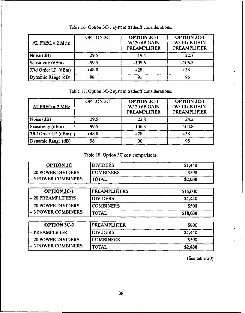
Table 16. Option 3C-1 system tradeoff considerations.
OPTION 3C OPTION 3C-1 OPTION 3C-1AT FREO = 2 MHz W/20 dB GAIN W/10 dB GAIN
PREAMPLIFIER PREAMPLIFIER
Noise (dB) 29.5 19.4 22.7
Sensitivity (dBm) -99.5 -108.6 -106.3
3Rd Order I.P. (dBm) +48.0 +28 +38
Dynamic Range (dB) 98 91 96
Table 17. Option 3C-2 system tradeoff considerations.
OPTION 3C OPTION 3C-1 OPTION 3C-1AT FREO = 2 MHz W/20 dB GAIN W/10 dB GAIN
PREAMPLIFIER PREAMPLIFIER
Noise (dB) 29.5 22.8 24.2
Sensitivity (dBm) -99.5 -106.3 -104.8
3Rd Order I.P. (dBm) +48.0 +28 +38
Dynamic Range (dB) 98 90 95
Table 18. Option 3C cost comparisons.
OPTION 3C DIVIDERS $1,440
- 20 POWER DIVIDERS COMBINERS $590- 3 POWER COMBINERS TOTAL $2,030
OPTION 3C-1 PREAMPLIFIERS $16,000- 20 PREAMPLIFIERS DIVIDERS $1,440
- 20 POWER DIVIDERS COMBINERS $590- 3 POWER COMBINERS TOTAL $18,030
OPTION 3C-2 PREAMPLIFIER $800
- PREAMPLIFIER DIVIDERS $1,440
- 20 POWER DIVIDERS COMBINERS $590- 3 POWER COMBINERS TOTAL $2,830
(See table 20)
38
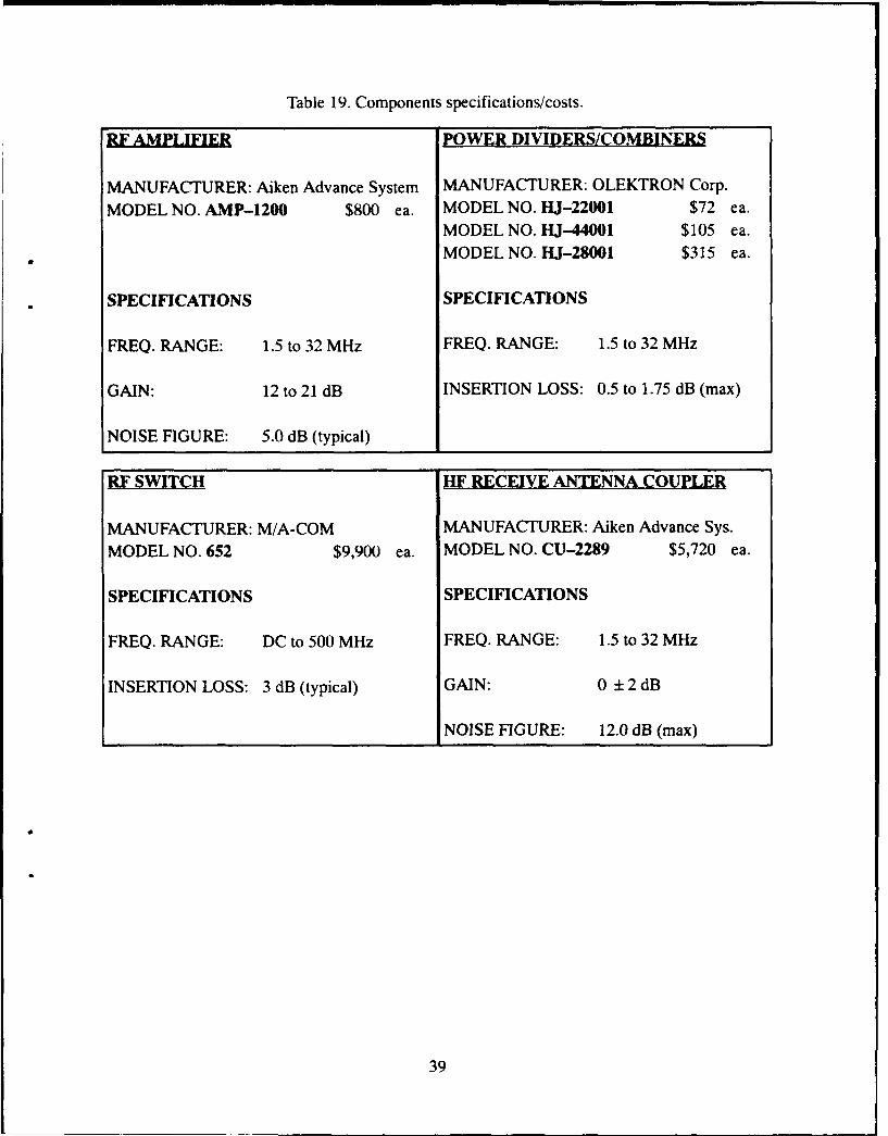
Table 19. Components specifications/costs.
RF AMPLIFIER POWER DIVIDERS/COMBINERS
MANUFACTURER: Aiken Advance System MANUFACTURER: OLEKTRON Corp.
MODEL NO. AMP-1200 $800 ea. MODEL NO. HJ-22001 $72 ea.MODEL NO. HJ-44001 $105 ea.MODEL NO. HJ-28001 $315 ea.
SPECIFICATIONS SPECIFICATIONS
FREQ. RANGE: 1.5 to 32 MHz FREQ. RANGE: 1.5 to 32 MHz
GAIN: 12 to 21 dB INSERTION LOSS: 0.5 to 1.75 dB (max)
NOISE FIGURE: 5.0 dB (typical)
RF SWITCH HF RECEIVE ANTENNA COUPLER
MANUFACTURER: M/A-COM MANUFACTURER: Aiken Advance Sys.MODEL NO. 652 $9,900 ea. MODEL NO. CU-2289 $5,720 ea.
SPECIFICATIONS SPECIFICATIONS
FREQ. RANGE: DC to 500 MHz FREQ. RANGE: 1.5 to 32 MHz
INSERTION LOSS: 3 dB (typical) GAIN: 0 ± 2 dB
NOISE FIGURE: 12.0 dB (max)
39
REPORT DOCUMENTATION PAGE OM oý 07408
Public reporting burden tor this collection of information is estimated to average 1 hour per response inciuding tie twne for reviewing in•trucfodti searching existing Cata sources gathering anomaintaining the data needed, and cornpiatig and reviewing the colfection of information Send comninents regarding this buroen estiniate or any other aspect of this collection of information inciuaingauggeetions for reducing this burdern. to Washington Headquawrers Services Directorate for Inrornalion Operations ano Reports, 1215 Jefferson Davis Highuway. Suite 1204 Arlington VA22202-4302, and to the Office of Management and Budget. Paperwork Reduction Project (0704-01688 Washington. DC 20503
I AGENCY USE ONLY fLaavoe bani) 2 REPORT DATE 3 REPORT TYPE AND DATES COVERED
September 1993 Final
4 TITLE AND SUBTITLE 5. FUNDING NUMBERS
SHIPBOARD IMPLEMENTATION AND CONCEPT OF OPERATIONS FORAUTOMATIC LINK ESTABLISHMENT PE: OMN
WU: ICCG98006. AUTHOR(S)a
I. C. Olson, L. M. Almazan
* 7 PERFORMING ORGANIZATION NAME(SI AND ADDRESS(ES) 8 PERFORMING ORGANIZATION
Naval Command, Control and Ocean Surveillance Center (NCCOSC) REPORT NUMBER
RDT&E Division TD 2575San Diego, CA 92152-5800
9 SPONSORING/MONITORING AGENCY NAME(S) AND ADDRESS(ES) 10 SPONSORING/MONITORINGAGENCY REPORT NUMBER
Space and Naval Warfare Systems CommandWashington, DC 20363-5100
11 SUPPLEMENTARY NOTES
12a. DISTRIBUTION/AVAILABIUTY STATEMENT 12b DISTRIBUTION CODE
Approved for public use; distribution is unlimited.
13 ABSTRACT (Maximum 2O words)
The scope of the task reported here was to develop implementation techniques and concepts of operation for using HF ALEtechniques, as presented in MIL-STD-188-141A, with shipboard systems designed to quickly establish good, reliable ship/beachand ship/ship communications (links and networks) for effective use by any control method/system.
14 SUBJECT TERMS 15 NUMBER OF PAGES
Automatic Link Establishment broadband receiving systems 50high-frequency systems 16 PRICE CODE
17 SECURITY CLASSIFICATION 18 SECURITY CLASSIFICATION 19 SECURITY CLASSIFICATION 20 LIMITATION OF ABSTRACTOF REPORT OF THIS PAGE OF ABSTRACT
UNCLASSIFIED UNCLASSIFIED UNCLASSIFIED SAME AS REPORT
NSN 754001 -20-5500 Standard form 296 (FRONT)

UNCLASSIFIED
21a. NAME OF RESPONSILE INDIVOU4L 21 b TELEPHONE (-eAin Ar- CoOe) 21c OFFICE SAtOL
I. C. Olson (619) 553-2579 Code 824
NPN 7540014-20 Sadwd fo r (MACK)
UNCLASSIFIED
INITIAL DISTRIBUTION
Code 0012 Patent Counsel (1)Code 02712 Archive/Stock (6)Code 0274B Library (2)Code 481 L.M. Almazan (1)Code 80 K.D. Regan (1)Code 804 G. A. Clapp (1)Code 811 T. A. Danielson (1)Code 811 P. Francis (1)Code 82 R. J. Kochanski (1)Code 824 J. B. Rhode (1)Code 824 1. C. Olson (9)Code 824 H. W. Guyader (1)Code 824 P. D. Donich (1)Code 824 C. S. Fuzak (1)
Defense Technical Information CenterAlexandria, VA 22304-6145 (4)
NCCOSC Washington Liaison OfficeWashington, DC 20363-5100
Center for Naval AnalysesAlexandria, VA 22302-0268
Navy Acquisition, Research and DevelopmentInformation Center (NARDIC)
Arlington, VA 22244-5114
GIDEP Operations CenterCorona, CA 91718-8000
NCCOSC Division DetachmentWarminster, PA 18974-5000
Chief of Naval OperationsWashington, DC 20350-2000 (2)
Space and Naval Warfare Systems Command2451 Crystal DriveArlington, VA 22245-5200 (9)
The Mitre CorporationMcLean, VA 22102-3481