ModSync Sequencing System - fulton.co.uk · The ModSync Sequencing System has ... The Lead Boiler...
43
ModSync Sequencing System Installation & Operation Manual For use with Fulton Steam Boilers. Revision 3.0 8/21/2008
Transcript of ModSync Sequencing System - fulton.co.uk · The ModSync Sequencing System has ... The Lead Boiler...

ModSync Sequencing System Installation & Operation Manual For use with Fulton Steam Boilers.
Revision 3.0 8/21/2008

- 2 -
Illustrator.exe.lnk

Table of Contents
Introduction Page 4
Features Page 4
Sequence of Operation Page 5
Installation Page 7
Time/Date Setup Page 10
Screen Descriptions Page 11
General - Page 13 Main Menu Screen - Page 14
System Status Screen - Page 15 Boiler Config Screens - Page 16
Process Config Screens - Page 18 Lead/Lag Screens - Page 20
Setback Schedule Screen - Page 24 Boiler Status Screen - Page 26
System Configuration Screens - Page 27 Alarm Screens - Page 32
Troubleshooting - Page 33
Modbus Network Page 35
Specifications Page 41 Warranty Page 42 Parts Information Page 43
- 3 -
Illustrator.exe.lnk

Introduction
The ModSync Sequencing System has been designed to provide precise pressure control of multiple Fulton Steam Boilers. The ModSync provides advanced functionality over existing sequencing systems. The enhanced Lead/Lag capabilities are provided through user-friendly displays and an easy to use Touchscreen Interface. This manual details the ModSync’s setup screens and configuration for use with Fulton Steam Boilers.
Features
• Lead/Lag Control The Steam boilers are staged on and off to match the existing load. The ModSync will stage additional boilers on automatically to maintain header pressure.
• Setback Schedule
The steam header setpoint can be configured to change based on the Time of Day and Day of the Week.
• Multiple Setpoint Control Modes The steam header setpoint can be field selected to be controlled by the ModSync, Remote 4-20mA Signal or SCADA Modbus Value.
• Alarm Status Boiler alarm status is monitored and annunciated via an Alarm Screen, minimizing troubleshooting time requirements.
• Alarm History
Alarm History screen provides Date, Time and Fault information for the last eight alarm occurrences.
• Modbus Communication The ModSync can communicate over the Modbus protocol to SCADA Systems.
• Steam System Interface
Remote Enable/Disable contacts and Alarm monitoring.
• Auto/Manual Mode Control
The ModSync can be configured for automatic or manual control of the Steam boilers. The Manual features help to decrease the boiler commissioning time by assisting with verification of the communication interface.
- 4 -
Illustrator.exe.lnk

Sequence of Operation
Designed to provide precise pressure control of a multiple steam boiler system, the ModSync stages the boilers based on load demands. A typical sequence of operation is as follows:
1. The ModSync monitors the steam header pressure using a pressure transducer. A PID Control Variable determines when the steam boilers will begin sequencing based on the difference between the actual header pressure and the steam pressure setpoint.
2. When a request for steam is determined by the ModSync, the Lead Steam Boiler is
energized. The initial firing rate (if applicable) is determined by the Lead Start Firing Rate variable set in the Lead/Lag configuration section.
3. If the steam pressure continues to decrease, the PID Control Variable will increase. The
Lead Steam boiler’s firing rate will reach 100% before the Lag Start CV value. The ModSync will enable a Lag Boiler when the Lag Boiler Start control variable value has been reached.
4. If additional steam is required, the ModSync will enable each additional Lag Boiler stage
determined by the Lag Stage Start CV value. Each Lag Stage will reach a 100% firing rate before the next stage is enabled.
5. As the steam pressure increases, the ModSync will begin to decrease the firing rate and
number of Steam boilers required to maintain the steam header pressure
7. The Lead Boiler is disabled when the steam pressure reaches a selectable value referenced around the steam header setpoint.
- 5 -
Illustrator.exe.lnk

- 6 -
Illustrator.exe.lnk

- 7 -
Illustrator.exe.lnk

Installation
Enclosure NEMA Classification: NEMA 12, 4, 4X. (IP 65)
Enclosure Dimensions
Figure 1.
- 8 -
Illustrator.exe.lnk

Installation
Location The ModSync enclosure (Figure 1) should be located in a clean, dry environment within visual range of the steam boilers. Four (4) mounting supports are provided loose in the enclosure. Secure the supports to the enclosure and mount the ModSync in an easily accessible area of the boiler room. Power SupplyA 120/230VAC-50/60HZ-1PH electrical supply is required by the ModSync. The supply should be connected to a 10A circuit breaker for short circuit protection. The incoming AC power should be connected to the corresponding L, N and Earth terminal blocks provided in the ModSync enclosure. Pressure SensorA Steam Header Pressure Sensor is provided with the ModSync. The pressure sensor range is based on the steam system design. The pressure sensor should be mounted in the common steam piping with a siphon loop isolating it from the header. Steam Boiler Interface The Steam Boilers provide status feedback using contact closures and analog (4-20mA) signals. Please reference the associated electrical diagram provided with the ModSync to determine the communication runs required between the ModSync and the Steam boilers.
- 9 -
Illustrator.exe.lnk

Installation
ModSync Program Download Instructions 1. Locate and extract the ModSync_Downloader .zip file. Locate the folder you extracted the
contents to and double-click the “ModSync_Downloader_165.exe” file to install the ModSync Downloader software program. Restart your computer.
2. Double-click on the provided .UDC file to open it in the ModSync Downloader. If the
Downloader does not open automatically, Click Start > All Programs > Unitronics > UniDownloader. Click the Open icon (first from left) and navigate to where the .UDC file is saved and open it.
3. Connect the serial communication cable from the communication port on the computer to
Port 1 on the ModSync.
4. Click on the Connection Settings icon (second from left). Select the appropriate Communication Settings and then click on the Get OPLC Information button to verify communication. V280 should be displayed in the “Model:” text box if communication is active. Click the Exit button when communication is active.
5. Click the Run icon (third from left) to start the download. Click Close after successfully
downloading the program. *Step 1 is only needed if the ModSync Downloader Software does not exist on your computer. Time/Date Update Instructions The following procedure describes the required steps to update the internal time and date of the ModSync control:
1. Press and hold the [?] key on the keypad for approximately 5 seconds. A password screen will appear. Enter 1111.
2. A screen labeled Data Types is displayed. Press the down arrow key once to display the
System screen. Press Enter.
3. Press the down arrow key two times so that the Time and Date block is highlighted. Press Enter.
4. To set the time - New time is highlighted on the screen. Press Enter and input the new time (24hr format) and press Enter.
5. To set the date, press the right arrow key when the New Time is highlighted and it will move you to the New Date area. Press Enter and the date field will be highlighted. Keep in mind that the Date field is Day/Month/Year format. Use the keypad to enter the new date and press Enter.
6. Press the Esc key until the ModSync Help Screen is displayed. The changes are now complete.
- 10 -
Illustrator.exe.lnk

- 11 -
Illustrator.exe.lnk

- 12 -
Illustrator.exe.lnk
Screen Descriptions
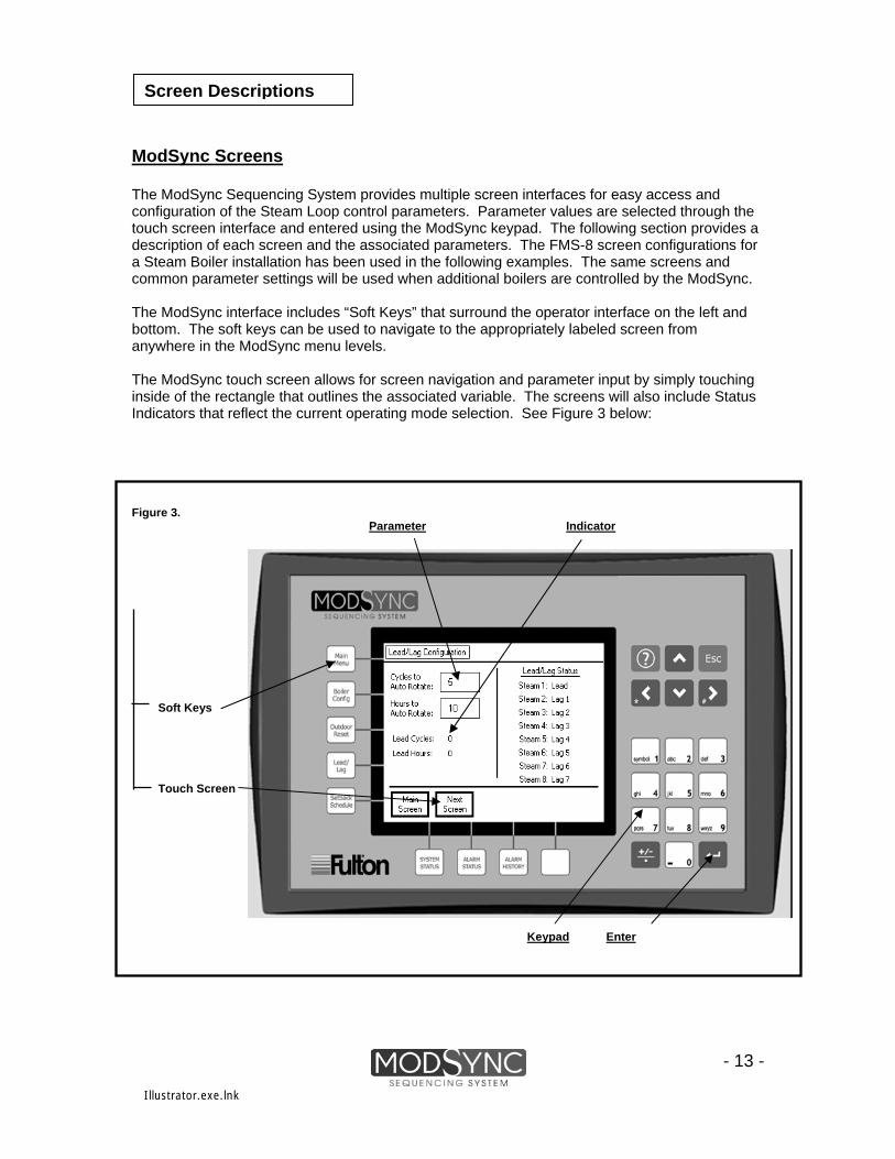
ModSync Screens The ModSync Sequencing System provides multiple screen interfaces for easy access and configuration of the Steam Loop control parameters. Parameter values are selected through the touch screen interface and entered using the ModSync keypad. The following section provides a description of each screen and the associated parameters. The FMS-8 screen configurations for a Steam Boiler installation has been used in the following examples. The same screens and common parameter settings will be used when additional boilers are controlled by the ModSync. The ModSync interface includes “Soft Keys” that surround the operator interface on the left and bottom. The soft keys can be used to navigate to the appropriately labeled screen from anywhere in the ModSync menu levels. The ModSync touch screen allows for screen navigation and parameter input by simply touching inside of the rectangle that outlines the associated variable. The screens will also include Status Indicators that reflect the current operating mode selection. See Figure 3 below:
- 13 -
Figure 3. Parameter Input Status Indicator Screen Navigation Soft Keys
Touch Screen
Keypad Enter Key
Illustrator.exe.lnk

Main Menu Screen
“Main Menu” Screen The Main Menu Screen is the first screen displayed when power is applied to the ModSync Sequencing System. This screen displays the current System Operating Mode, the Date/Time and current program revision. The Main Menu also provides a touch screen interface to select other screens.
- 14 -
Illustrator.exe.lnk

System Status Screen
“System Status” Screen The System Status screen is the main ModSync screen. This screen displays the current pressure status of the Steam loop, the header setpoint and the Control Variable value. The current Steam boiler status is also displayed.
- 15 -
Illustrator.exe.lnk
Boiler Configuration Screens
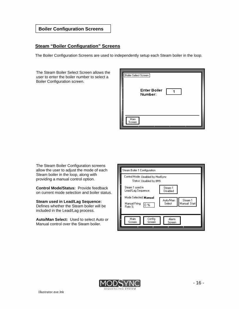
Steam “Boiler Configuration” Screens The Boiler Configuration Screens are used to independently setup each Steam boiler in the loop.
- 16 -
The Steam Boiler Select Screen allows the user to enter the boiler number to select a Boiler Configuration screen.
The Steam Boiler Configuration screens allow the user to adjust the mode of each Steam boiler in the loop, along with providing a manual control option. Control Mode/Status: Provide feedback on current mode selection and boiler status. Steam used in Lead/Lag Sequence: Defines whether the Steam boiler will be included in the Lead/Lag process. Auto/Man Select: Used to select Auto or Manual control over the Steam boiler.
Illustrator.exe.lnk

Steam Boiler Configuration Screen
Fulton Setting
Parameter
Range Description
Enabled
Enabled /Disabled
Steam used in Lead/Lag Sequence Touchscreen operator that allows the user to independently Enable/Disable each of the Steam boilers in the loop. A Disabled boiler will not be used in the Lead/Lag sequence and cannot be controlled by the ModSync.
- 17 -
Auto
Auto/Manual
Auto/Man Select Touchscreen operator that allows the user to select the Operation mode of each Steam boiler. In Auto mode, the ModSync will control operation of the boiler. In Manual mode, the user can Start/Stop the Steam boiler and manually enter a firing rate.
Steam Manual Start/Stop
Start / Stop Touchscreen operator that allows the user to start and stop the Steam boiler while in Manual mode.
Manual Firing Rate % Touchscreen operator that allows the user to manually enter the firing rate of the Steam
boiler when in Manual mode. 0% 0% to 100%
Boiler Configuration Screens
Illustrator.exe.lnk

Process Configuration Screen
“Process Configuration” Screen The Process Configuration Screen is used to define the Steam loop pressure based on the header pressure and configuration of associated parameters.
The Process Configuration screen is used to set the header pressure setpoint. Separate setpoint variables are available and used based on the Setback Schedule. To adjust the Setpoint: Touch the operator corresponding to the pressure that you wish to adjust. A cursor will appear in the block. Using the keypad, enter the new pressure and press the Enter key on the keypad.
- 18 -
Illustrator.exe.lnk

Process Configuration Screen
Fulton
Parameter
Range
Description
Setting
150 psi
0 to 150 psi
Normal Mode Setpoint Setpoint used when the ModSync is in Normal Mode operation as selected by the Setback Schedule.
120 psi
Setback Mode Setpoint
- 19 -
0 to 150 psi
Setpoint used when the ModSync is in Setback Mode operation as selected by the Setback Schedule.
Setpoint Mode Control ModSync ModSync
Remote Determines what setpoint the ModSync uses to sequence the boilers. ModSync mode uses the setpoint provided from the Process Config screen. Remote uses a 4-20mA signal supplied from the customer. BMS uses a modbus supplied setpoint.
BMS
Loop Sensor Range (High) 200 psi 30 psi Header Sensor range high value. The pressure sensor supplied has a range determined by
the type of steam system (0-30, 0-100, and 0-200). The Loop Sensor Range High value needs to be set at the high-end value of the sensor.
100 psi 200 psi
Process Configuration Screen
Illustrator.exe.lnk
Lead/Lag Configuration Screens
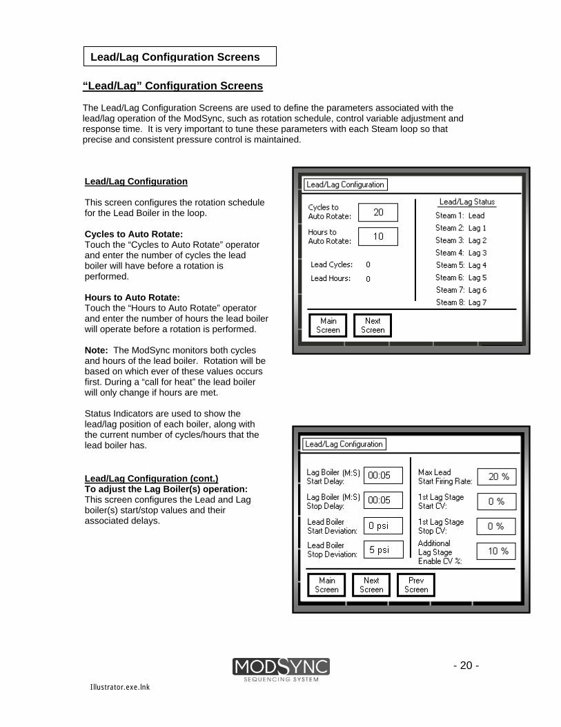
“Lead/Lag” Configuration Screens The Lead/Lag Configuration Screens are used to define the parameters associated with the lead/lag operation of the ModSync, such as rotation schedule, control variable adjustment and response time. It is very important to tune these parameters with each Steam loop so that precise and consistent pressure control is maintained.
- 20 -
Lead/Lag Configuration This screen configures the rotation schedule for the Lead Boiler in the loop. Cycles to Auto Rotate: Touch the “Cycles to Auto Rotate” operator and enter the number of cycles the lead boiler will have before a rotation is performed. Hours to Auto Rotate: Touch the “Hours to Auto Rotate” operator and enter the number of hours the lead boiler will operate before a rotation is performed. Note: The ModSync monitors both cycles and hours of the lead boiler. Rotation will be based on which ever of these values occurs first. During a “call for heat” the lead boiler will only change if hours are met. Status Indicators are used to show the lead/lag position of each boiler, along with the current number of cycles/hours that the lead boiler has.
Lead/Lag Configuration (cont.) To adjust the Lag Boiler(s) operation: This screen configures the Lead and Lag boiler(s) start/stop values and their associated delays.
Illustrator.exe.lnk

Lead / Lag Configuration Screens
Default
Description Parameter
Range Setting
Cycles to Auto Rotate: Touchscreen operator that defines the number of cycles the lead boiler will have before it is rotated.
20 1 to 9999
1
1 to 9999 Hours to Auto Rotate: Touchscreen operator that defines the number of hours the lead boiler will have before it is rotated.
Default Setting
Parameter Range Description
Lag Boiler Start Delay (M:S):
00:30 00:00 to 99:99 (M:S) Touchscreen operator that allows the user to enter a delay before each lag boiler stage starts.
This helps to prevent short cycling of the lag stages. Lag Boiler Stop Delay (M:S):
Touchscreen operator that allows the user to enter a delay before each lag boiler stage stops. This helps to prevent short cycling of the lag stages. 00:30
00:00 to 99:99 (M:S)
Lead Boiler Start Deviation: Touchscreen operator that allows the user to enter a deviation from setpoint before the lead boiler starts. If the setpoint is 120psi and the start deviation is 5psi, the lead boiler will not start until the steam loop pressure drops to 115psi.
5 psi
-99psi to 99psi
Lead Boiler Stop Deviation: Touchscreen operator that allows the user to enter a deviation from setpoint before the lead boiler stops. If the setpoint is 120psi and the stop deviation is 5psi, the lead boiler will not stop until the steam loop pressure reaches 125psi.
0 psi
-99psi to 99psi
Lead High Flame Stage Start CV: Touchscreen operator that defines the Control Variable value that will bring the lead boiler on high flame. The CV value will be determined by the PID parameters selected on the second Lead/Lag Config screen.
20%
0% to 100%
Lag 1 Low Flame Stage Start CV: Touchscreen operator that defines the Control Variable value that will bring the first lag boiler on low flame. The CV value will be determined by the PID parameters selected on the second Lead/Lag Config screen.
10% 0% to 100%
Lag 1 High Flame Stage Start CV: Touchscreen operator that defines the Control Variable value that will bring the first lag boiler on high flame. The CV value will be determined by the PID parameters selected on the second Lead/Lag Config screen.
30% 0% to 100%
Lag 2 Low Flame Stage Start CV: Touchscreen operator that defines the Control Variable value that will bring the second lag boiler on low flame. The CV value will be determined by the PID parameters selected on the second Lead/Lag Config screen.
40% 0% to 100%
Lag 2 High Flame Stage Start CV: Touchscreen operator that defines the Control Variable value that will bring the second lag boiler on high flame. The CV value will be determined by the PID parameters selected on the second Lead/Lag Config screen.
50% 0% to 100%
Lead/Lag Configuration Screens
- 21 -
Illustrator.exe.lnk

Lead/Lag Configuration Screens
“Lead/Lag” Configuration Screens continued:
- 22 -
The next “Lead/Lag” Screen is used to configure the PID parameters that determine the Control Variable (CV). The CV is used to stage the Steam boilers on and off based on the steam loop heat requirements. Proportional, Integral, Derivative: Variables that determine reaction of the Control Variable based on the steam loop heat load changes. Manual Reset: Allows a shift in the control band to utilize low fire operation. PID Status: Provide status information regarding the PID loop for troubleshooting purposes.
Illustrator.exe.lnk

Lead / Lag Configuration Screens
Default
Parameter
Range Description
Setting
Proportional Band (% of 200): 20 0% to 100% Touchscreen operator that defines the proportional band setting for the steam loop.
Integral Time (Units of 1 sec): Touchscreen operator that defines the Integral time base for the steam loop. 0 0 to 240 seconds
Derivative Time (Units of 1 sec): Touchscreen operator that defines the Derivative time base for the steam loop. 0 0 to 240 seconds
Manual Reset Value (psi): Touchscreen operator that shifts the PID controlling setpoint. Manual Reset will adjust the PID loop to control off of the actual setpoint minus the Manual Reset value. This will keep the lead boiler at low fire after the Manual Reset setpoint until the Lead Boiler Stop Deviation pressure value is reached.
5 psi -100psi to100psi
Lead/Lag Configuration Screens
- 23 -
Illustrator.exe.lnk

Setback Schedule Screen
“Setback Schedule” Configuration Screen
- 24 -
The “Setback Schedule” screen is used to define the operating mode of the steam loop based on the Day of the Week and Time of Day. There are two modes that the steam loop can operate in: Normal and Setback. The Setback Schedule determines the mode of operation based on how the Normal mode time for each day has been configured. The steam loop will be in Setback mode when the actual time is outside the defined Normal mode timeframe. Normal Mode: Defines the start and stop times for each day that the steam loop will be in Normal mode. To change the time, simply touch the operator and a cursor will appear. Use the keypad to enter a new time (24Hr format) and press the Enter key. Mode Change: Allows the user to select auto or manual control over the steam loop mode. Mode Select: Allows the user to select the steam loop mode when the Mode Change is in Manual.
- Building is in Normal Mode.
- Building is in Setback Mode.
Illustrator.exe.lnk

Fulton Setting
Parameter
Range Description
Normal Mode Start/Stop (24Hr Time of Day): Start: 06:00 00:00 to 23:59 Touchscreen operator that defines the Normal mode start time and stop time for each day of
the week. Stop: 20:00
Mode Change: Auto Auto Touchscreen operator that determines if the steam loop mode will be automatically controlled
by the programmed time schedule or will be manually controlled by the user. Manual
Mode Select: Normal Normal Touchscreen operator that defines the steam loop mode if the Mode Change is set to
manual. Setback
Setback Schedule Screen
- 25 -
Illustrator.exe.lnk
Boiler Status Screen
“Boiler Status” Screen
- 26 -
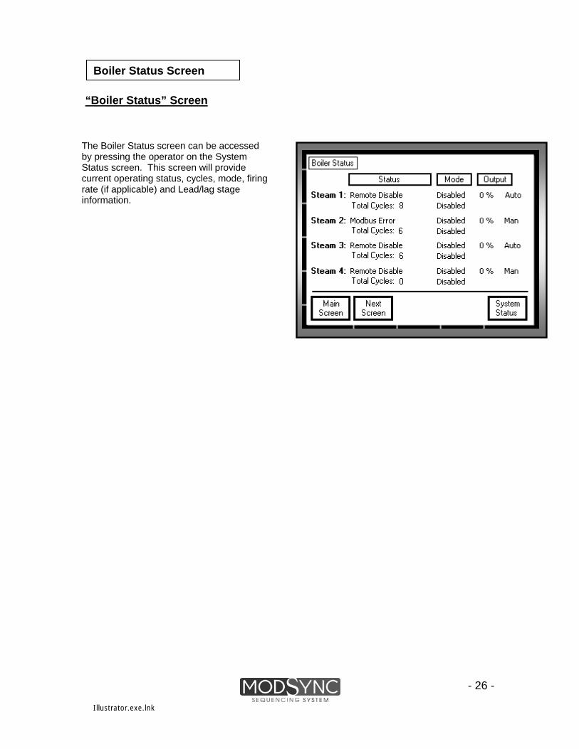
The Boiler Status screen can be accessed by pressing the operator on the System Status screen. This screen will provide current operating status, cycles, mode, firing rate (if applicable) and Lead/lag stage information.
Illustrator.exe.lnk

“System Configuration” Screens The System Configuration Screen Menu allows access to multiple values used to configure the ModSync. This screen can be accessed by pressing the unlabeled soft key while on the Main Screen.
System Configuration Screens
- 27 -
Illustrator.exe.lnk

BMS Interface Configuration: Used to configure the communication parameters between the ModSync and a Building/Energy Management System. Web Server Configuration: Defines the server login and page refresh rate. The login for the web server will be “mod” and the four-digit login number (ex. mod0000).
System Configuration Number of Boilers: Select the number of boilers that the ModSync will interface with. Default Factory Settings: Pressing this operator sets all of the ModSync variables back to their factory default settings. Scaling Configuration Remote SP Scaling: Defines the analog input (4 – 20 mA) range when a remote setpoint signal is used.
System Configuration Screens
Illustrator.exe.lnk
- 28 -
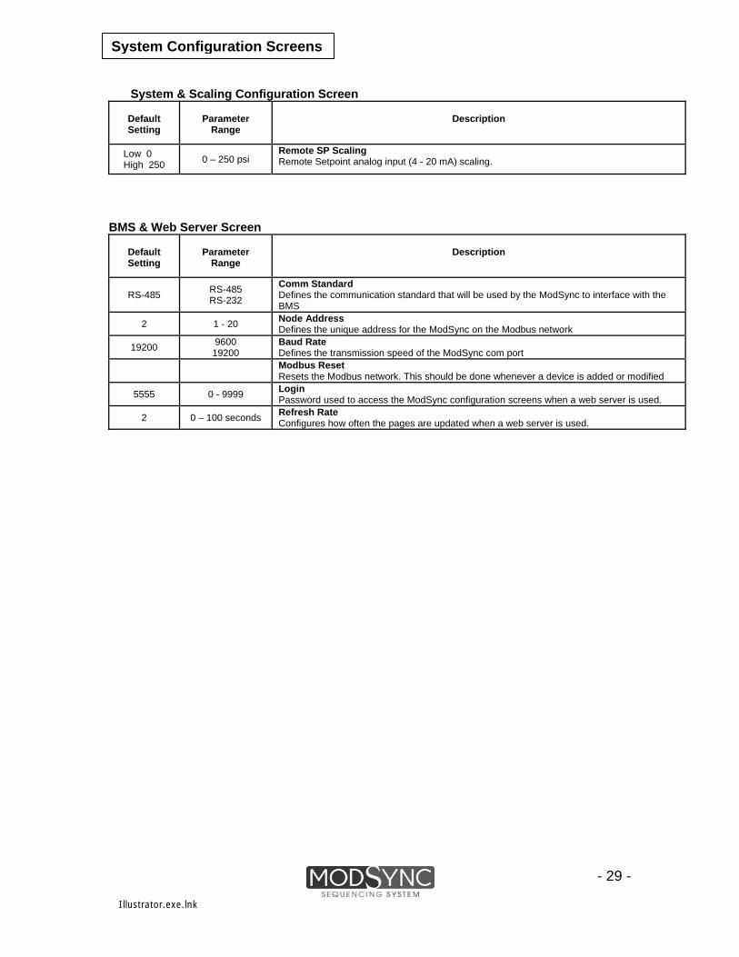
System Configuration Screens
System & Scaling Configuration Screen
Default Setting
Parameter
Range
Description
Low 0 High 250 0 – 250 psi
Remote SP Scaling Remote Setpoint analog input (4 - 20 mA) scaling.
BMS & Web Server Screen
Default Setting
Parameter
Range
Description
RS-485
Comm Standard RS-485 RS-232 Defines the communication standard that will be used by the ModSync to interface with the
BMS
2 1 - 20 Node Address Defines the unique address for the ModSync on the Modbus network
19200 9600 19200
Baud Rate Defines the transmission speed of the ModSync com port
Modbus Reset Resets the Modbus network. This should be done whenever a device is added or modified
5555 0 - 9999 Login Password used to access the ModSync configuration screens when a web server is used.
2 0 – 100 seconds Refresh Rate Configures how often the pages are updated when a web server is used.
- 29 -
Illustrator.exe.lnk

System Configuration Screens
Steam Sensor Input: The Steam Sensor configuration allows for selection of where the ModSync will receive the actual header pressure signal. Alarm Configuration: The Alarm Delay prevents the ModSync from disabling a boiler until the boiler’s alarm input has been activated for the user defined time delay. The Boiler Enable after Alarm Clear, if in Auto, will allow the boiler to be automatically re-enabled if the boiler alarm is cleared. The Alarm History can also be cleared.
Password Configuration: Allows a 4-digit password to be entered that prevents unauthorized access to the setup screens. The Password Bypass Timer allows access to the setup screens (once the password has been entered) for the configured time. When the password bypass timer expires, the password will need to be entered to access the setup screens.
Maintenance Configuration: The Preventive Maintenance Boiler Hours is used to define the number of run hours for the boilers before a PM is required. The Cycle Status displays the number of cycles for each boiler in the loop.
Illustrator.exe.lnk
- 30 -

System Configuration Screens
Password & Screen Saver Configuration Screen
Default Setting
Parameter Range Description
0
0 - 9999
New Password 4-digit password required to access setup screens. Setting to 0 removes the password requirement.
5:00 0 to 99:99 (MM:SS)
Password Bypass Timer Setup screens can be accessed for this time period after the password has been entered.
Enabled Enabled Disabled
Status Enables/Disables the ModSync screensaver option.
0 to 99:99 (MM:SS) 5:00 Time
Defines the timeframe the ModSync will wait before entering screensaver mode.
10:00 0 to 99:99 (MM:SS)
Dim Time Defines the timeframe the ModSync will wait before dimming the ModSync screen.
Maintenance Configuration Screen
Default
Parameter Range
Setting
Description
2000 0 - 8760
Preventative Maintenance Boiler Hours Configures the number of run hours before a boiler preventative maintenance is required.
0 0-999,999 Cycle Status Displays the current cycle count for each boiler. The cycle count can be modified by selecting the rectangle next to the boiler description and entering the new value.
Sensor & Alarm Configuration Screen
Default
Parameter Range Description
Setting
- 31 -
ModSync ModSync
BMS
Header Sensor Determines where the header pressure input is being received from. If ModSync is selected, a header pressure sensor is sending the signal directly to the ModSync. If BMS is selected, a Modbus value is being provided to the ModSync.
Header BMS Value Visual indicator of the setpoint being received from the external device if ModBus is being used. Alarm Delay Determines the delay time between when an alarm from the boiler is received to when the ModSync disables the boiler.
0 to 99:99 (MM:SS) 00:00
Boiler Enable after Alarm Clear Defines if the boiler will automatically be re-enabled at the ModSync after the local alarm is cleared. In Manual, the boiler will need to be re-enabled at the ModSync even if the local alarm has been reset.
Auto Auto Manual
Alarm History Clears the ModSync alarm history.
Illustrator.exe.lnk
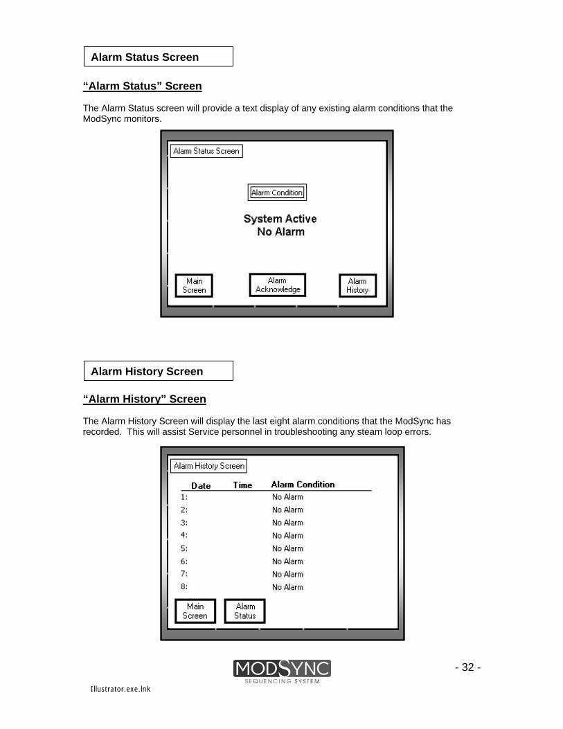
Alarm Status Screen
“Alarm Status” Screen The Alarm Status screen will provide a text display of any existing alarm conditions that the ModSync monitors.
- 32 -
Alarm History Screen
“Alarm History” Screen The Alarm History Screen will display the last eight alarm conditions that the ModSync has recorded. This will assist Service personnel in troubleshooting any steam loop errors.
Illustrator.exe.lnk
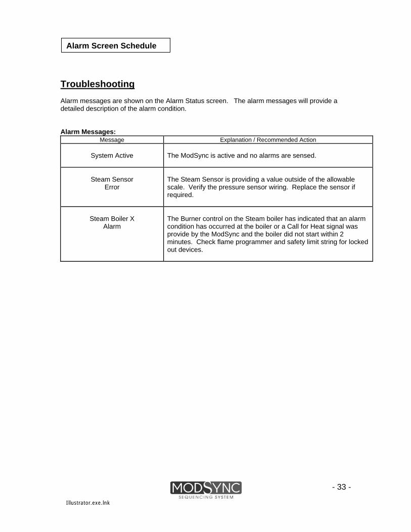
Troubleshooting Alarm messages are shown on the Alarm Status screen. The alarm messages will provide a detailed description of the alarm condition. Alarm Messages:
Message Explanation / Recommended Action
System Active The ModSync is active and no alarms are sensed.
Steam Sensor Error
The Steam Sensor is providing a value outside of the allowable scale. Verify the pressure sensor wiring. Replace the sensor if required.
Steam Boiler X The Burner control on the Steam boiler has indicated that an alarm
condition has occurred at the boiler or a Call for Heat signal was provide by the ModSync and the boiler did not start within 2 minutes. Check flame programmer and safety limit string for locked out devices.
Alarm
Alarm Screen Schedule
- 33 -
Illustrator.exe.lnk

- 34 -
Illustrator.exe.lnk

- 35 -
Illustrator.exe.lnk

- 36 -
Illustrator.exe.lnk

Modbus Network
Network Parameter Configuration and Address Listings. The ModSync Sequencing System provides a Modbus interface to communicate the status of each steam boiler in the loop to a SCADA System. This network can also be used to receive start/stop and remote setpoint commands from the SCADA System. The following tables detail the communication parameters and the ModSync addresses available for an FMS-2 through FMS-8 Steam System. Communication The following communication parameters should be used when configuring a ModSync Communication Network:
- 37 -
Parameter Setting
Protocol Modbus (RS-485), RTU.
Baud Rate 9600, 19200
Start Bits 8
Parity None
Timeout 5 Seconds.
Nodes Up to 20.
Illustrator.exe.lnk

ModSync Addresses
Modbus Network
Modbus Registers Address Description Range Units 2001 (R/W) Steam Loop Pressure 0 to 150 psi 2002 (R/W) Modbus Setpoint Input (if applicable) 0 to 150 psi 2003 (R/W) ModSync Setpoint Mode 0 - ModSync 1 – Remote SP 2 - BMS 2004 (R) ModSync Setpoint psi 2005 (R) ModSync Alarm Code 0 – No Alarm 1- Steam Sensor 2 – N/A 3 – Steam 1 Alarm 4 – Steam 2 Alarm 5 – Steam 3 Alarm 6 – Steam 4 Alarm 7 – Steam 5 Alarm 8 – Steam 6 Alarm 9 – Steam 7 Alarm 10 – Steam 8 Alarm 11 – Modbus Alarm 2006 (R) Steam 1 Firing Rate 0 to 100 % 2008 (R) Steam 2 Firing Rate 0 to 100 % 2010 (R) Steam 3 Firing Rate 0 to 100 % 2012 (R) Steam 4 Firing Rate 0 to 100 % 2014 (R) Steam 5 Firing Rate 0 to 100 % 2016 (R) Steam 6 Firing Rate 0 to 100 % 2018 (R) Steam 7 Firing Rate 0 to 100 % 2020 (R) Steam 8 Firing Rate 0 to 100 %
- 38 -
Illustrator.exe.lnk
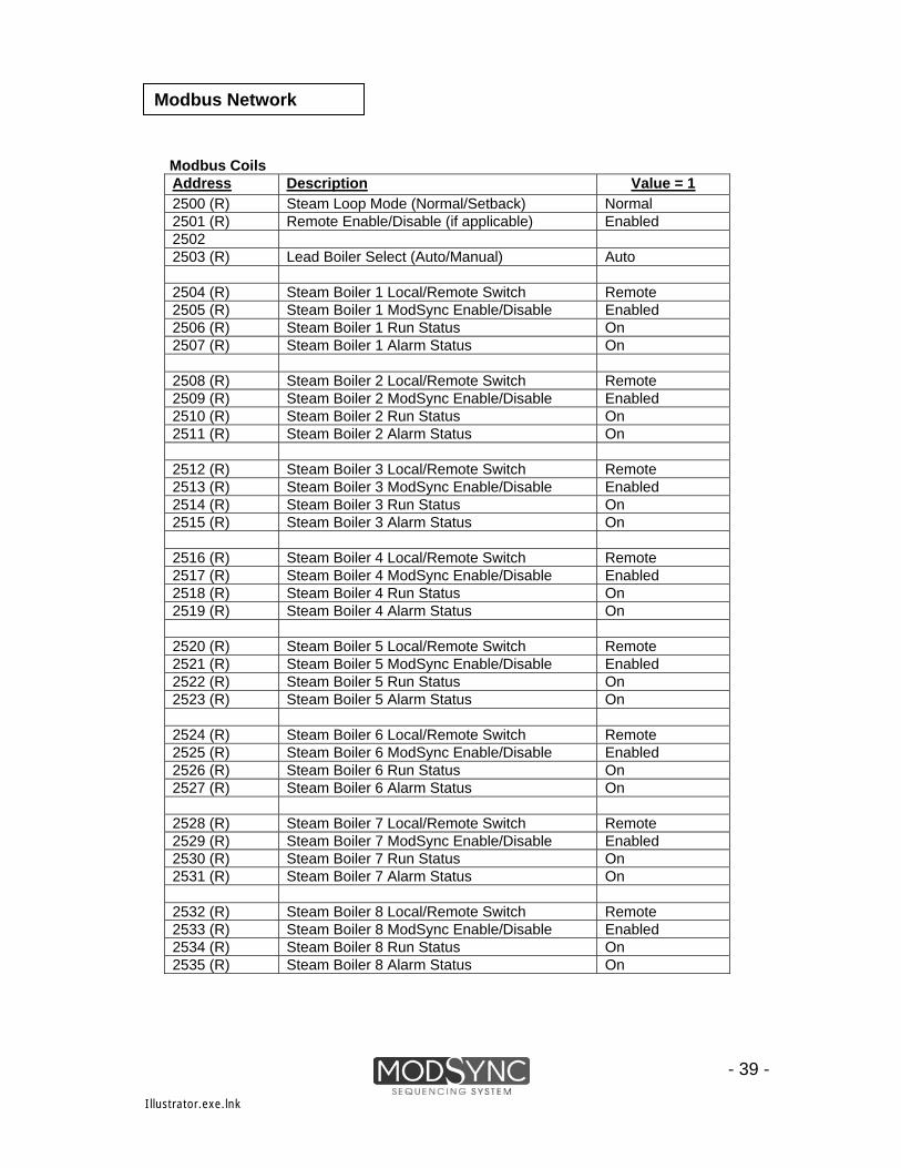
Modbus Network Modbus Coils
Address Description Value = 1 2500 (R) Steam Loop Mode (Normal/Setback) Normal 2501 (R) Remote Enable/Disable (if applicable) Enabled 2502 2503 (R) Lead Boiler Select (Auto/Manual) Auto 2504 (R) Steam Boiler 1 Local/Remote Switch Remote 2505 (R) Steam Boiler 1 ModSync Enable/Disable Enabled 2506 (R) Steam Boiler 1 Run Status On 2507 (R) Steam Boiler 1 Alarm Status On 2508 (R) Steam Boiler 2 Local/Remote Switch Remote 2509 (R) Steam Boiler 2 ModSync Enable/Disable Enabled 2510 (R) Steam Boiler 2 Run Status On 2511 (R) Steam Boiler 2 Alarm Status On 2512 (R) Steam Boiler 3 Local/Remote Switch Remote 2513 (R) Steam Boiler 3 ModSync Enable/Disable Enabled 2514 (R) Steam Boiler 3 Run Status On 2515 (R) Steam Boiler 3 Alarm Status On 2516 (R) Steam Boiler 4 Local/Remote Switch Remote 2517 (R) Steam Boiler 4 ModSync Enable/Disable Enabled 2518 (R) Steam Boiler 4 Run Status On 2519 (R) Steam Boiler 4 Alarm Status On 2520 (R) Steam Boiler 5 Local/Remote Switch Remote 2521 (R) Steam Boiler 5 ModSync Enable/Disable Enabled 2522 (R) Steam Boiler 5 Run Status On 2523 (R) Steam Boiler 5 Alarm Status On 2524 (R) Steam Boiler 6 Local/Remote Switch Remote 2525 (R) Steam Boiler 6 ModSync Enable/Disable Enabled 2526 (R) Steam Boiler 6 Run Status On 2527 (R) Steam Boiler 6 Alarm Status On 2528 (R) Steam Boiler 7 Local/Remote Switch Remote 2529 (R) Steam Boiler 7 ModSync Enable/Disable Enabled 2530 (R) Steam Boiler 7 Run Status On 2531 (R) Steam Boiler 7 Alarm Status On 2532 (R) Steam Boiler 8 Local/Remote Switch Remote 2533 (R) Steam Boiler 8 ModSync Enable/Disable Enabled 2534 (R) Steam Boiler 8 Run Status On 2535 (R) Steam Boiler 8 Alarm Status On
- 39 -
Illustrator.exe.lnk

- 40 -
Illustrator.exe.lnk

- 41 -
Illustrator.exe.lnk

ModSync Limited Warranty
Fulton warrants that it will replace or repair any ModSync components or part thereof which is found defective in workmanship or material, within one year from the date of installation or 18 months from the factory shipment date, whichever comes first. The foregoing is in lieu of all other warranties, expressed or implied, and Fulton specifically disclaims any and all merchantability or fitness for a particular purpose. Under no circumstances shall Fulton, its authorized Representatives, affiliated or subsidiary companies be liable for special, consequential or incidental damages. Liability by Fulton shall be limited to replacement or repair of the ModSync or associated ModSync components only.
- 42 -
Illustrator.exe.lnk

Specifications
ModSync Sequencing System Model: FMS Mechanical:
Size: Height: 420mm; Width: 370mm; Depth: 211mm Weight: 10 Kgs
Environmental:
Operating Temp: 32ºF to 125ºF (0ºC to 52ºC) Storage Temp: -20ºF to 150ºF (-28ºC to 65ºC) Front Panel: NEMA 4, IP65
Electrical:
Input Power: 120/230 VAC (+/- 10%), less than 2 Amps. Agency Listings: UL 508A – Industrial Control Panels. Parts Information
- 43 -
Part Number Description
2-45-001034 ModSync Operator Interface Terminal
2-45-001039 I/O Expansion Module
2-45-001035 Expansion Adapter
2-45-001038 RS-485 Communication Port
2-45-001040 24VDC Power Supply
Illustrator.exe.lnk