Modernization of instrumentation and control in nuclear ...
187
XA9847291 _ 30/ IAEA-TECDOC-1016 Modernization of instrumentation and control in nuclear power plants Report prepared within the framework of the International Working Group on Nuclear Power Plant Control and Instrumentation IAEA May 1998 29- 33
Transcript of Modernization of instrumentation and control in nuclear ...

XA9847291 _ 30/
IAEA-TECDOC-1016
Modernization ofinstrumentation and control
in nuclear power plants
Report prepared within the framework of theInternational Working Group on
Nuclear Power Plant Control and Instrumentation
IAEAMay 1998
29- 33
The IAEA does not normally maintain stocks of reports in this series.However, microfiche copies of these reports can be obtained from
IN IS ClearinghouseInternational Atomic Energy AgencyWagramerstrasse 5P.O. Box 100A-1400 Vienna, Austria
Orders should be accompanied by prepayment of Austrian Schillings 100,in the form of a cheque or in the form of IAEA microfiche service couponswhich may be ordered separately from the INIS Clearinghouse.

IAEA-TECDOC-1016
Modernization ofinstrumentation and control
in nuclear power plants
Report prepared within the framework of theInternational Working Group on
Nuclear Power Plant Control and Instrumentation
INTERNATIONAL ATOMIC ENERGY AGENCY
May 1998

The originating Section of this publication in the IAEA was:
Nuclear Power Engineering SectionInternational Atomic Energy Agency
Wagramer Strasse 5P.O. Box 100
A-1400 Vienna, Austria
MODERNIZATION OF INSTRUMENTATION AND CONTROLIN NUCLEAR POWER PLANTS
IAEA, VIENNA, 1998IAEA-TECDOC-1016
ISSN 1011-4289
©IAEA, 1998
Printed by the IAEA in AustriaMay 1998

FOREWORD
This report has been produced in response to the perceived need for collective consideration of theissues and approaches to plant modernization that is becoming necessary, as many operating nuclearpower reactors approach 20-30 years of operation. The need for this, particularly for instrumentationand control (I&C) systems was pointed out by the IAEA International Working Group on Nuclear PowerPlant Control and Instrumentation (IWG-NPPCI). Further discussion of the topic at the IAEA SpecialistsMeeting on Modernization of Instrumentation and Control Systems in Nuclear Power Plants held inGarching, Germany, 4-7 July 1995, confirmed this need and determined that international support wouldbe available.
The first IAEA Advisory Group Meeting on Modernization of Instrumentation and ControlSystems in Nuclear Power Plants was held in Vienna from 25 to 29 March 1996 in order to exchangeinformation on the national experience on I&C modernization in nuclear power plants and to prepare anextended outline of the planned report on this subject. The first draft, which was prepared after thatmeeting by the members of the project team, was significantly improved during a consultants meetingheld in Vienna from 2 to 6 December 1996. The comments received on the first draft were carefullyconsidered and incorporated into a new draft report. This was distributed to the full project team foradditional comments.
The second IAEA Advisory Group Meeting on Modernization of Instrumentation and ControlSystems in Nuclear Power Plants was held in Vienna from 14 to 18 April 1997 to finalize the technicalcontent of this report and to exchange information on the national experiences with I&C modernizationin nuclear power plants. This report was finalized during a consultants meeting held in Vienna from 3 to7 November 1997.
The scope of the modernization activities described in this report covers a wide range ofactivities. It includes the modernization of equipment in operating plants and partially built plants. Itcovers the full range of types of I&C systems including protection, safety, control and informationsystems. It is applicable for a plant throughout its life. This report includes appropriate consideration ofthe increasingly international nature of the I&C systems supply industry. It takes advantage of theactivities and lessons learned in the different national approaches to develop general guidance andrecommendations. However, the report does not seek to provide advice on how the specific differentnational licensing processes should be approached. The audience for the report is all those consideringI&C system changes.
Special thanks are due to W. Bastl of GRS (Germany) and J. Naser of EPRI (United States ofAmerica) who chaired the working meetings and co-ordinated the work. A. Kossilov, who initiated theproject, and V. Neboyan, Nuclear Power Engineering Section, Division of Nuclear Power, whocompleted the work, are the IAEA officers responsible for the preparation of this publication.

EDITORIAL NOTE
In preparing this publication for press, staff of the IAEA have made up the pages from theoriginal manuscripts as submitted by the authors. The views expressed do not necessarily reflectthose of the IAEA, the governments of the nominating Member States or the nominatingorganizations.
Throughout the text names of Member States are retained as they were when the text wascompiled.
The use of particular designations of countries or territories does not imply any judgement bythe publisher, the IAEA, as to the legal status of such countries or territories, of their authoritiesand institutions or of the delimitation of their boundaries.
The mention of names of specific companies or products (whether or not indicated asregistered) does not imply any intention to infringe proprietary rights, nor should it be construedas an endorsement or recommendation on the part of the IAEA.
The authors are responsible for having obtained the necessary permission for the IAEA toreproduce, translate or use material from sources already protected by copyrights.

CONTENTS
1. INTRODUCTION 1
2. PRESENT SITUATION AND THE NEEDS FOR MODERNIZATION 2
3. TERMINOLOGY 4
3.1. Technical 4
3.2. Organizational 6
4. STRATEGY 6
4.1. Introduction 6
4.2. General approach 74.3. Current state of I&C systems in the plant 84.4. Plant policies and external requirements 94.5. Utility defined requirements and constraints 104.6. Definition of the vision for I&C systems 114.7. Preliminary analysis of the impact of plant-wide considerations on
specific I&C systems 124.8. Detailed analysis to validate preliminary decisions and
identify best approach 134.9. Definition of the migration path 134.10. Quality assurance, verification and validation, and
configuration management 145. MANAGERIAL ASPECTS 16
5.1. Introduction 165.2. Project considerations 165.3. Project planning 16
5.3.1. System independent requirements 175.3.2. Standardized platforms 175.3.3. Standardized interfaces 175.3.4. Project implementation 17
5.4. Participants in the project 185.4.1. Acquiring knowledge of the existing system 185.4.2. Designing a new system 185.4.3. Utility participation in the system design 195.4.4. Contract arrangements 19
5.5. Project phases 205.5.1. Feasibility studies and project planning 205.5.2. Design, construction and testing 215.5.3. Site preparation and installation 215.5.4. Taking the new systems into operation 215.5.5. Interface to the regulator 21
5.6. Project organization and project handbook 22
6. ESTABLISHING THE DESIGN CRITERIA 22
6.1. Introduction 226.2. General aspects 23

6.2.1. Important issues 236.2.2. Influence from policy and general design decisions 236.2.3. Technology characteristics 236.2.4. Characteristics of programmable technology 256.2.5. New functions implemented by software 26
6.3. Safety requirements 266.3.1. Safety goals 266.3.2. Deterministic requirements 276.3.3. Probabilistic requirements 286.3.4. System reliability and availability 29
6.4. Compliance with safety standards and guides 306.4.1. International standards and practices 316.4.2. Project internal rules and standards 32
7. OPERATIONAL ISSUES 32
7.1. Introduction 327.2. Operational philosophy 33
7.2.1. Balance between automation and human actions 337.2.2. Staffing 347.2.3. Task analysis 357.2.4. The main control room 357.2.5. Technical support centre 357.2.6. Emergency operating facility 357.2.7. Access rights and security 36
7.3. Operational human-machine interfaces 367.3.1. General requirements 377.3.2. Conventional displays and VDUs 387.3.3. Integration of the information presentation in displays 397.3.4. VDU display hierarchy and access 397.3.5. Presentation of alarms 407.3.6. Computerized support systems 40
7.4. Non-operational human—machine interfaces 427.4.1. Serving information needs of various groups of people 427.4.2. Field communication stations 427.4.3. Maintenance tools 437.4.4. Control engineering tools 437.4.5. Design databases 437.4.6. Office automation 43
7.5. Verification and validation of control room solutions 437.5.1. Methods for the V&V process 437.5.2. Validating the operability of the plant 44
7.6. Procedures and training 447.6.1. Scope and depth of training 447.6.2. Operating procedures 457.6.3. Commissioning tests and their instructions 457.6.4. Needs for a period of parallel operation 45
7.7. Documentation 457.7.1. Coexistence of different technology 46
8. ENGINEERING INFRASTRUCTURE 46
8.1. Introduction 468.2. The I&C Infrastructure 46
8.2.1. Communications 46

8.2.2. Existing and new networks 488.2.3. Security 50
8.3. Impact of and on other systems 508.3.1. Existing I&C 508.3.2. Strategy for modifying common service systems 518.3.3. Environmental control 51
9. ENGINEERING REQUIREMENTS AND CONSTRAINTS 52
9.1. Introduction 529.2. Requirements 52
9.2.1. Recovery of old requirements 529.2.2. Generation of new requirements 539.2.3. Functional requirements 549.2.4. Qualification requirements 589.2.5. Maintenance requirements 62
9.3. Limitations and constraints 669.3.1. Physical space 669.3.2. Layout 679.3.3. Ventilation 679.3.4. Cabling and connectors 679.3.5. Access to the plant 689.3.6. Ranges of input and output signals 689.3.7. Power supplies 69
10. LICENSING ASPECTS 69
10.1. Introduction 6910.2. Review of the country regulatory environment 7010.3. Communication with the regulatory body in the course of the project 7110.4. Safety case of an I&C modernization project 73
11. TESTING AND COMMISSIONING 75
11.1. Introduction 7511.2. Planning of testing and commissioning activities 7511.3. Data acquisition subsystems 7811.4. Control systems 7811.5. Computer hardware and communication networks 7911.6. System software 8111.7. Configuration level software/data 8211.8. Human-machine interface 8211.9. Links to the off-line systems 8311.10. Integrated testing 8311.11. Parallel running 8311.12. Full scale simulator 8411.13. Specific checks against safety principles 8411.14. Documentation 85
12. CONCLUSIONS 85
APPENDIX A: EQUIPMENT TECHNOLOGY DEFINITIONS 89
APPENDIX B: RECOVERY OF OLD REQUIREMENTS EXAMPLE 91

REFERENCES 95
ANNEX: COUNTRY REPORTS
NPP I&C system modernization in the Czech Republic: The NPP Dukovany example 101P.Krs
Modernization projects at Finnish NPPs 107B. Wahlstrom, K. Simola
French practice of the renovation of I&C systems in the 900 MW NPPs I l lA. Dall 'agnol
First experiences from system integration, installation and commissioning ofTELEPERM XS for reactor I&C at the Unterweser NPP 119O. Schorner
Modernization of I&C in the Paks nuclear power plant 131A. Hetzmann, J. Eiler, Z. Toth
The status of I&C development in the Republic of Korea 135IS. Koo, K.C. Kwon, J. W. Lee
Main trends in modernization of I&C systems at NPPs in the Russian Federation 151A.B. Pobedonostsev, A.G. Chudin
Modernization of I&C: a stepwise learning process with a final vision 157P. van Gemst
Modernization of the Ukrainian NPP instrumentation and control systems 165M. Yastrebenetsky
Activities at the Electric Power Research Institute to support the modernization ofinstrumentation and control systems in nuclear power plants in theUnited States of America 175J. Naser
CONTRIBUTORS TO DRAFTING AND REVIEW 185

I. INTRODUCTION
Most existing instrumentation and control (I&C) systems in nuclear power plants (NPPs)throughout the world were designed with analog equipment and relays. These were the only availabletechnologies when NPPs were designed 25-45 years ago. A majority of them are still operating withmuch of their original I&C equipment or with obsolete digital equipment both of which arebecoming, or already are, obsolete, costly to operate, or degrading in performance. Utilities are facedwith increasing operating and maintenance (O&M) costs to maintain acceptable performance of thisequipment in their plants. There is also a need in many plants for safety or performanceimprovements. The use of analog equipment and relays limited the ability of the original designers toimplement features that could improve the overall operation of NPPs. With modern technology,especially digital technology, the issues of the obsolescence of analog and aged digital equipment canbe addressed. These issues include the lack of availability of spare parts and the deterioration of theinfrastructure of suppliers to support this ageing equipment. Moreover, many performanceimprovements that were not feasible or practical with analog equipment can now be effectivelyimplemented with modem technology. Potential improvements such as integrated controls; newfunctionality; reduced duplication of equipment, functionality, and information; reduced O&M costs;enhanced safety; increased performance; and integrated information for the user can now be realizedwith modern technology. This is especially feasible with digital systems. In addition, moderntechnology offers improved reliability and cost-effective operation which has been demonstrated inother process industries.
Many of these ageing systems in NPPs need to be modernized in a reliable and cost-effectivemanner to eliminate the problem of a lack of spare parts and supplier support, to reduce O&M costs,to improve plant performance, and to enhance safety. Digital I&C systems need to play a major rolein nuclear power plants to achieve real productivity improvements and enhance the competitivenessof the plant. However, modernization of I&C equipment brings with it several challenges. Theseinclude the determination of which systems to modernize, what technology to use for a particularmodernization project, how to implement new systems and new technologies in the plant, how todevelop new systems with new technology so that they will work together with older systems in thepower plant which are based on a different technology, how to develop and implement safe andreliable systems, how to address new concerns that digital technology brings with it such as softwareverification and validation and video display based human-machine interfaces, how to develop digitalsystem requirements, what is needed to support licensing, and many other related questions.
This report is designed to identify methodologies, guidelines, processes, concerns, and goodpractices to help in the modernization of I&C systems of NPPs. It has been developed by thecontributors from their experience in identifying the need for modernization and in the performance ofactual modernization planning and implementation projects. The methodologies, guidelines, processes,and good practices identified in this report have been developed for and tested on actual modernizationactivities. It is expected that the user of this report will be able to gain valuable information andexperience that will allow future modernization projects to be performed more cost-effectively. Thissame information and experience will allow the modernized systems and components to beimplemented in a manner that will improve productivity, reduce costs, and enhance safety.
The term "modernization" is used in this report to represent the three types of changes in I&Csystems and components. These are the replacement of old systems and components, the upgrading ofold systems and components, and the implementation of new systems and components. The term"replacement" is used when an existing system is replaced with a new or improved technology butthere is no change in its capabilities. The term "upgrading" is used when an existing system isreplaced with a new or improved technology and there is an increase in its capabilities. The term"new" is used when a new system with new functionalities is implemented in the plant. The scope ofthese modernizations cover a wide range of activities. It includes the modernization of equipment inoperating plants and the modernization of equipment and designs in partially built plants. It covers

large, complex systems; small systems, and individual components in systems. It also covers thecomplete replacement of all of the I&C equipment in a plant. It covers the full range of types of I&Csystems including protection, safety, control, and information systems. It is applicable for a plantthroughout it's lifetime.
This report is structured to follow the probable life-cycle of a modernization activity. It starts byconsidering the issues driving changes in I&C systems and components and the strategy to be adoptedto make these changes. Section 2 describes the motivations that drive modernization projects innuclear power plants. Section 3 describes the terminology used in this report. Section 4 describes theoverall strategic planning required for cost-effective modernization of I&C systems. Managementissues for modernization projects are addressed in Section 5. Section 6 describes the process ofestablishing design criteria. Section 7 discusses operational issues with I&C modernization. Section 8describes the engineering infrastructure to support I&C modernizations. Engineering requirementsand constraints, licensing issues, and testing and commissioning of I&C systems are discussed inSections 9, 10, and 11 respectively. Section 12 gives a summary of the important aspects of thisreport and presents a list of recommendations for modernization projects.
2. PRESENT SITUATION AND THE NEEDS FOR MODERNIZATION
Nuclear power plants throughout the world are confronted by some or all of the following threemajor concerns. The first concern is a growing obsolescence problem with I&C systems, which is asignificant contributing factor to increasing costs for plant operation and maintenance. Plant agecombined with the rapid pace of the evolution of electronic technology is a significant factor in I&Cequipment obsolescence. The inability to obtain spare parts and supplier support is a major problemwith obsolete equipment. The second concern is the increasing need for improved competitivenessbrought on by deregulation and other market forces. This necessitates improved productivity, cost-effective modernization projects, and reduced O&M costs for the continued operation of the plant.The third concern is the need to improve the safety of the plant and to be able to modify the plant sothat it can meet new safety standards and requirements. The consequence of not being able to addressthis problem is that the plant will not be able to operate. The concerns of obsolescence andcompetitiveness, if not addressed appropriately, can also lead to the shutting down of the power plant.Therefore, nuclear power plants are faced with crucial decisions as to the appropriate strategy forcontinued operation of the plant, continued system maintenance, system replacement, and systemupgrade.
The flexibility and performance advantages of modern technology can be used as the basis formodernizing I&C equipment in the plant in a cost-effective manner to address all three of theseconcerns. The realization of the benefits from the use of modem technology is highly dependent onthe way it is implemented in the power plant. It is important to use reliable and cost-effectiveapproaches for the design, development, qualification, implementation, and maintenance of replaced,upgraded, and new I&C systems in the plant. It is also important to understand that moderntechnology solutions bring about different requirements and issues than older analog technology. Inaddition, the use of a combination of old and new technologies in the plant also introduces new issuesand concerns.
The ageing of I&C equipment in many cases causes additional inspection and maintenanceactivities to maintain acceptable performance and safety margins of the equipment. In addition, theavailability of spare parts and supplier support decreases as the equipment becomes obsolete. Thisleads to increased costs for spare parts and supplier support, if they can be obtained at all. Theincreased work to maintain acceptable performance and the decreased availability of parts andsupplier support lead to increased O&M costs. In addition, some of these older systems may lead toincreased trip vulnerability and safety challenges. They may also make it difficult or impossible tomeet new safety standards and requirements. These concerns and the increased costs make it

important to develop strategies to determine which systems need to be modernized and the mosteffective way to perform the modernizations.
Adequate quality assurance associated with the I&C systems plays an important role for highintegrity systems in nuclear power plants. For older systems, regardless of their real quality, thisvigorous quality assurance process may be lacking, or the quality of documentation does not meet thestandards of today. In this case, the lack of confidence in the quality of a system, which is applied in asensitive area of the plant, may also provide the need for modernization of the system.
The use of modern technology in the power plant offers the opportunity to increaseproductivity, to reduce O&M costs, to enhance safety, and to support plant staff in the performance oftheir jobs. Modem technology can be used to improve availability, improve reliability, increaseproductivity, and reduce safety challenges to the plant. Proper use of this technology can not onlyreduce the potential for human errors, but can also support improved human performance. Someexamples of how modem technology can support cost-effective and safe power productive are givenbelow.
In some cases, the power output of the plant could be increased by having more accuratesystems and by being able to more accurately calculate parameters in the plant. Computerized I&Csystems are well suited to perform complex calculations on the basis of the measured data taken fromthe plant. With these systems, it is possible; for example, to operate the plant closer to its limits,which will result in a gain in power production without reducing the safety margins. This can be donebecause there is a reduction in the uncertainties that were originally used in the determination of thesafe operating limits of the plant.
Exploiting the capabilities of modem technology for I&C systems; such as enhanced accuracy, higherreliability; and accessibility of complex calculations; would allow more realistic or optimizedsituations. Typical examples are:
- A smart core monitoring system can be used to achieve a flatter power distribution in the core.In this case, local power peaks are minimized, and the whole core output power can be higher,while still remaining safely below the operating limits.
- A more accurate control system could allow the limiting parameters of the turbine and thesecondary loop to be set closer to the operational limits due to the elimination or reduction ofso-called engineering design margins.
- Intelligent closed loop controllers can be used to perform sophisticated control operations toreduce power losses during transient situations.
Operating and maintenance costs can be reduced through the use of modem technology.Reduced operating costs can be achieved; for example, by better utilization of the fuel, lessconsumption of auxiliary power resources, and the slowing down of the fatigue process of expensivemechanical components. To do this, requires I&C systems based on modem technology. Someexamples are:
Sophisticated monitoring of the burnout of the fuel in the core could considerably reduce fuelcosts.
A fast, on-line water chemistry control system could reduce corrosion damage in components.
A fatigue monitoring system could follow the fatigue process so that it would be possible totake the necessary corrective actions before failure.

- A good quality controller could protect components from rapid changes in parameters and;therefore, slow down the fatigue process.
Reduced maintenance costs can be achieved; for example, by diagnostic systems, self-testingsystems, self-calibrating systems, systems that do not drift over time, and systems that require onlyminimal maintenance. Extended self-testing during operation not only reduces the amount ofrepetitive testing, but also makes the test coverage more complete. It also reduces the potential forhuman error. The test data can be easily fed into a maintenance network database to supportadditional analysis, trending, and diagnosis. These capabilities can support condition basedmaintenance, which reduces unnecessary maintenance and may prevent forced outages due toequipment failures since the condition based maintenance will indicate when maintenance is actuallyneeded.
Operator support systems, including diagnostic systems, will support more cost-effectiveoperation. They too require modem technology for implementation. I&C systems developed foroperator support; for example, safety parameter display systems (SPDS) and success path monitoringsystems, and for diagnostic systems; for example, loose parts monitoring and vibration monitoringsystems, can be realized in an effective manner only by means of computer based systems. Thesesystems offer the ability of providing useful information to the operator to allow the operation of aplant to be more effective and safe.
The extensive data, information processing, and display capabilities of modern technologysupport the ability to improve considerably human-machine interfaces in the plant. This includes theeffective use of VDU and large overview screens in the control room, the presentation of complexsituations by means of specialized graphs and diagrams, and the ready access to information thatsupports the more efficient running of the plant. These improved human-machine interfaces reducethe potential for human error and support improved productivity and enhanced safety.
It is clear that there are many reasons to perform system modifications in nuclear power plants.In some cases, they are needed to get away from problems and concerns such as obsolete equipment,increasing O&M costs, increased safety requirements, and vulnerability to less reliable or lessavailable equipment. In other cases, the modernization of systems is needed to achieve positiveimprovements, such as more power output, increased diagnostic ability, increased operationalflexibility, increased availability, and reduced potential for human error. Therefore, it is important toperform these I&C system modernizations in a planned, cost-effective manner. In addition, when amodernization is being done to respond to a concern, the utility should also consider taking advantageof the opportunity to enhance the system to support more cost-effective power production as opposedto just replacing it with the same functionality.
3. TERMINOLOGY
3.1. TECHNICAL
ACASICAvailability
BWRCADCCFCEACMCMF
alternating current;application specific integrated circuit;fraction of time that a system is actually capable of performing itsmission;boiling water reactor;computer aided design;common cause failure;control element assemblyconfiguration management;common mode failure;

Commissioning
Configurable software
Configuration managementCPUCSSDBMSDNBREMCEMIEOFExisting accessible software
Existing proprietary software
FMEAFPGAFuzzy logic
HMIHVACI&CI/OLANLCMLCMPLEDLOCALPDMACMaintainability
MCRMTBFMTTRNew softwareNPPO&MOSSOSPESPLCPLDPFFOPSAPWRQAQCQuality Assurance
process during which plant components and systems, having beenconstructed, are made operational and verified to be in accordance withdesign assumptions and have to meet the performance criteria; itincludes both nuclear and non-nuclear tests;software that already exists but is configured for the specificapplication using data or an application specific input language;configuration control and change management;central processing unit;computerized support system;database management system;departure from nucleate boiling ratio;electromagnetic compatibility;electromagnetic interference;emergency operating facility;software from a similar application that is to be reused and for which allof the documentation is available;commercial product or software from another application that meets allor part of the current application requirements but for which littledocumentation is available;failure mode and effects analysis;field programmable gate array;consistent approach to manipulating qualitative data representingapproximations rather than firm categories;human-machine interface;heating ventilation and air conditioning;Instrumentation and control;input/output;local area network;life-cycle management;life-cycle management plan;light emitting diode;loss of coolant accident;local power density;medium access control layer;ability to keep plant components and systems operational and verifiedto be in accordance with performance and safety criteria;main control room;mean time between failure;mean time to repair;software written specifically for the application;nuclear power plant;operating and maintenance;operator support system;operating system;programmable electronic system;programmable logic controller;programmable logic devices;probability of failure free operation;probabilistic safety assessment;pressurized water reactor;quality assurance;quality control;programme that identifies to all concerned a basis for control of allactivities affecting quality, monitors the performance of these activities

Quality Control
RAMRBMKReliability
RFIROMRPSSPDSSTATCP/IPTesting
TSCUPSValidation
VDUVerification
V&VWWER
3.2. ORGANIZATIONAL
EPRIIAEAIECIEEEISONUREGRGTMIUSNRC
in accordance with the defined and documented procedures, andensures that the specified quality is achieved;process performed to check that the specified software developmentmethods and process in the QA plan have been correctly followed;random access memory;Russian channel graphite moderated water cooled reactor design;probability that a device, system or facility will perform its intendedfunction satisfactorily for a specified time under stated operatingconditions;radio frequency interference;read only memory;reactor protection system;safety parameter display system;shift technical adviser;transmission control protocol/Internet protocol;determination or verification of the capability of an item to meetspecified requirements by subjecting the item to a set of physical,chemical, environmental, or operational conditions;technical support centre;uninterruptable power supply;test and evaluation of the integrated computer system (hardware andsoftware) to ensure compliance with the functional, performance, andinterface requirements;visual display unit;process determining whether or not the product of each phase of thedigital computer system development process fulfills all of therequirements imposed by the previous phase;verification and validation;Russian pressurized water reactor design.
Electric Power Research Institute;International Atomic Energy Agency;International Electrical Commission;Institute of Electrical and Electronics Engineers;International Standardization Organization;Reports series of USNRC;Regulatory guides of the USNRC;Three Mile Island nuclear power plant;United States Nuclear Regulatory Commission.
4. STRATEGY
4.1. INTRODUCTION
Instrumentation and control systems in nuclear power plants need to be modernized in asystematic, reliable, and cost-effective manner. To achieve the maximum benefits from I&Cmodernization, it is important for the utility to develop long-term planning and implementationstrategies which include the definition of the vision for the plant at the end of the utility's chosenplanning period. The strategy will be to look at the existing I&C systems in the context of the entireplant to determine which ones should be maintained, replaced, or upgraded. It will also identify whennew I&C systems need to be implemented in the plant. The strategy will prioritize these I&C

modernization activities. It will identify the communications, network, computing, and human-machine interface (HMI) infrastructure required to implement the modernization so that the visionwill be achieved in a systematic manner. When I&C modernization is performed incrementally, thestrategy and infrastructure will ensure that each modernization step will be performed in a mannerthat leads to the achievement of the plant vision.
4.2. GENERAL APPROACH
As problems usually arise at the maintenance level for a given I&C system or component,utilities have usually performed a modernization of that particular piece of equipment without takinginto consideration the plant as a whole. This means that traditionally systems have been implementedand maintained in a stand-alone manner creating isolated islands of functionality and information.This has frequently resulted in increased O&M costs and in the unnecessary duplication of functionsand information in the plant. This approach has reduced the effectiveness, and in some cases thepossibility, of using systems that are more advantageous for existing and enhanced functionalities. Anintegrated approach is essential to maintain consistency with existing I&C systems, to allow furthermodifications to the I&C systems, and to maximize the effectiveness of new and upgraded systems.Modem technology available for distributed digital systems, plant process computers, and plantcommunications and computing networks is fully capable of supporting the integration of new andupgraded systems and of information and; therefore, of facilitating the implementation of thisintegrated approach. This capability of modern technology and its effectiveness has been proven inother process industries.
The integrated approach does not mean that the modernization of the I&C systems must beperformed in one step requiring large capital resources and a long plant shut down period, although itcould be done this way. The integrated approach means considering the final goal for the plant (thevision) during each phase of the modernization, leaving the options available to move ahead in theright direction when the decision is made to carry out the next stage of the modernization. Putting thenecessary infrastructure in place to leave these options open could result in additional expensesduring the early phases of modernization. However, the infrastructure will facilitate futuremodernization efforts so that the overall costs will end up to be less than doing each one individually.In addition, the infrastructure will allow the modernized systems to perform more efficiently as awhole which will support additional cost savings.
It is important to make modernization decisions based on the overall vision for the plant so thata particular modernization supports the overall vision and the future modernization activities. Thisway the modernization will not create the problems that occur when stand-alone decisions are made.A life-cycle management programme, and therefore a life-cycle management plan (LCMP) is neededto allow comprehensive, global, and systematic decision-making on the modernization of I&Csystems. This plan is a long range, plant-specific plan that defines how a utility will manage its I&Csystems over a specified time period which is determined by the utility. Depending on the utility'smission and objectives, some systems will be maintained in their present configuration and otherswill be replaced or upgraded using modern technology. Therefore, the plan must support the use of amixture of modern and older technology in the plant. Life-cycle management also involves makingdecisions on the modernization of a system based on the entire life-cycle of that system. This meansthat decisions should not be made on just implementation costs but on all relevant costs includingthose of maintenance, operation, and training. To implement the I&C Life-cycle Management (LCM)in the plant, the utility needs to define the:
present I&C configuration;- desired I&C configuration for the end of a utility-defined planning period;- plan for reaching the desired configuration;- I&C maintenance strategy for those systems that will be maintained in their present
configuration.

LCM provides an integrated approach to I&C system management, as opposed to maintainingor modernizing each system as an isolated project. It involves a comprehensive analysis of all I&Csystems included in the scope of the LCMP, as well as other issues such as plant human-machineinterfaces, obsolescence, maintenance problems, standardization, improved performance, andcommunications and networking. By considering these factors, the utility can develop a set ofstrategies to be used in the maintenance, replacement, and upgrading of each existing I&C system.This, in addition to an emphasis on standardization and the use of high-quality commercial products,will promote consistent solutions to similar issues for having multiple platforms used in varioussystems. This approach bases the decisions on justifiable arguments which can be presented tomanagement when needed.
The major benefit of the LCM approach to a utility is that it provides the strategic andsystematic aspects necessary to managing I&C systems. The LCM approach stresses:
establishment of plant objectives, constraints, and assumptions at the beginning of the processto ensure that the LCMP is developed in accordance with the overall goals of the plant;
co-ordination with existing plant strategic plans, task forces, etc. to ensure that the overallstrategies of the plant are addressed;
- in-depth analysis of each I&C system to determine which systems can be cost-effectivelymaintained so that only necessary replacements and upgrades are performed.
An example of a methodology that can be used to develop a plant-specific LCMP is the onedeveloped by the Electric Power Research Institute (EPRI) [1].
4.3. CURRENT STATE OF I&C SYSTEMS IN THE PLANT
Since their commissioning, the I&C systems and components in the plant have usuallyundergone modifications. There are several reasons for these modifications including the addition offunctionality, performance or safety enhancements, and technological improvements. Experience hasshown that most of the time, especially for the oldest units, parts of these modifications have not beenfully documented or part of the documentation itself has been lost. However, it is necessary to knowprecisely the present state of the I&C systems and components and their operating history (for as longas possible) in order to make appropriate decisions for the modernization of them.
Verification and the updating of existing documentation is a must for further modernizationactions to determine the true current state. The necessary upgrading of the documentation is a costlyand time consuming activity, so in many cases this is avoided and instead the issues of modernizationare addressed without having good quality documentation. This approach can be dangerous since itcould jeopardize the success of the whole modernization project. The documentation for existing,modernized, and new I&C systems should be maintained throughout the life of the systems.
The approach to define the current state of the plant's I&C systems consists in identifying theI&C systems and components, identifying the required information, collecting and validating thisinformation, and describing the boundary interfaces between the I&C systems and components. Theboundary interfaces are important since they establish the boundary conditions to be met whenincremental modernization is done. Even when the modernization is performed all at once, boundaryinterfaces will still exist with other plant equipment outside the modernization programme. Ifnecessary, this approach can be iterated on in order to make the results more complete and reliable.
A baseline description of each of the existing I&C systems of interest and of the plant networkarchitecture is needed to understand the current state of the systems and to support the decisions thatwill be made to retain or modernize the systems. While the primary intention is to describe the

existing systems and architecture, the baselining process also queries plant personnel about neededand desired functions that do not currently exist. The new functions that are appropriate and practicalcan be incorporated into the design of new and upgraded systems. The information obtained here todo this baselining will also be useful and sometimes necessary for the development of functionalrequirements and bid specifications in the future. The baseline description for each candidate I&Csystem should include the following sections:
- general information (e.g. system ID, manufacturer, supplier support, location, safety class);
system summary (e.g. functionality, configuration, safety challenges caused by the system,current performance, loss of generated power due to the unavailability of the system, interfaces,security, documentation);
- physical characteristics (e.g. number of cabinets, detailed component inventory, limits,boundaries, environment, location, power supply, grounding, margins in the cabinets and therooms for power supply, amount of information exchanged between cabinets, connectionmodes with instrumentation and other systems);
- system constraints (e.g. licensing commitments, technical specifications, design constraints,operating characteristics, failure mode requirements);
- obsolescence issues (e.g. maintenance costs, replacement parts, performance degradation,proficiency of plant maintenance shifts, supplier support);
problems and potential improvements (e.g. functionality, configuration, performance,maintenance);
cost-benefit/risk analysis of further operation and modernization;
references.
In addition to the I&C systems and components, common points exist and must be identified.These points include sensors, actuators, cabling, electrical power supply, ventilation, I&C roomswhere control equipment is installed, and the control rooms, especially the main control room. Theircurrent status and capabilities must be identified. The state of the instrumentation must be described.The same questions that are asked and answered for the I&C systems should be asked and answeredfor the sensors and actuators (i.e. general information, physical characteristics, constraints, etc.). Theage effects on cables should be evaluated (e.g. resistance to fire, state of the outer jacket sheathensuring insulation, the margins on cable support systems, etc.). The electrical power supply sourcesneed to be studied taking into account voltage, consumed power, and margins. Each I&C room mustbe studied from the point of view of ventilation, space, and fire area. The main control room, and theprocessing and display of alarms, can be affected by any I&C modification.
The information collected must be relevant, exhaustive and reliable. Past experience has shownthat this information is scattered among several organizations and people. It is important to define agood process to collect and validate the needed information. This information needs to be thoroughlydocumented.
4.4. PLANT POLICIES AND EXTERNAL REQUIREMENTS
The main goal of the plant policy is to cost-effectively produce power. This goal is becomingeven more rigorous under the new deregulated electric utility industry environment in manycountries. The plant policy will identify the goals and objectives of the utility. These goals and

objectives will have a major effect on the modernization activities for I&C systems. The plant policywill be driven substantially by the utilities short and long term business plans.
Other projects and plans in the utility, that are either planned or ongoing, will also effect thepolicy and scheduling of the modernization of I&C systems. Examples of these are the growth ofgenerated power by increasing the efficiency of some of the physical processes or by the betterutilization of some of the components (e.g. fuel), planned lifetime extension through improved ageingmonitoring, plant process computer replacements, safety reassessment, fire sectorizationreassessment, information management system upgrades, installation of equipment to supportcommunications amongst plants and corporate offices, etc. Maintainability and obsolescenceconcerns of the systems after they are modernized need to be part of the planning process.
The external requirements that effect I&C modernization must also be identified. Someexamples of these are regulatory requirements, load following requirements, commitments to thepublic and regulatory bodies, etc. This combination of plant policy and external constraints willdetermine the plant vision and drive the modernization activities.
The specific situation of the plant and where it resides in its life-cycle will dictate differentways to satisfy the overall plant policies and external requirements. For example, a plant that has justbecome operational will probably see the needs to increase power production and enhance safety tobe a higher priority than addressing increasing O&M costs due to obsolescence initiated problems.However, as the plant ages, the obsolescence concerns and needs to satisfy new safety requirementswill rise in priority.
4.5. UTILITY DEFINED REQUIREMENTS AND CONSTRAINTS
There are several requirements and constraints defined internally by the utility that must besatisfied by the I&C modernization activities. These requirements and constraints must be identifiedand satisfied in the implementation plans for I&C modernization. It is important, when theserequirements and constraints are determined, to take into account input from operating, maintenance,engineering, management, licensing, etc. These requirements and constraints include functional (e.g.needed and desired functions that do not currently exist), physical (e.g. available rack space andventilation), technological (e.g. what technologies are available and what are their capabilities andlimitations), economic (e.g. available capital resources and required pay back period), safety (e.g.technical specifications and regulatory commitments), versatility (e.g. flexibility and expandability),and human related (e.g. levels of automation and lighting). The decision on whether themodernization of systems and groups of systems will be done all at once or in an incremental processover time will also add requirements and constraints to the modernization process.
The utility will create requirements and constraints by defining how it wants to perform thevarious aspects of modernization. The utility should develop a set of plant-specific guidelines to beused for I&C modernization projects to address issues such as functional requirements and bidspecification development, licensing, communications and computing environment, softwareverification and validation (V&V), hardware qualification including electromagnetic compatibilityand seismic, failure analysis, commercial grade equipment acceptance, human-machine interfaces,and the integration of systems and information through communications networks. Significantadvantages can be obtained by issuing an utility level guideline identifying the preferred equipmenttypes and families that must be used for modernization activities, i.e. standardization. This can reducethe costs of training and spare parts, as well as simplifying integration. One concern with this is thatsuch a limitation excludes the competition between manufacturers which may result in higher costs.This problem could be avoided by making long term agreements with the suppliers for predefinedprice discounts. Another approach is to include a small number of preferred equipment types orfamilies into the guideline.
10

The above guidelines will define what needs to be done for a system and identify the necessaryrequirements and constraints affecting the system. When an engineer needs to specify a new systemor the modernization of an existing one, the guidelines can be used to ensure satisfaction of the plantpolicies, external requirements, utility constraints and goals in a manner consistent with the overallplant vision. Examples of some methodologies, guidelines, handbooks, and a user's guide that havebeen put together by EPRI to help develop these plant-specific guidelines are given in Refs [2-21].
4.6. DEFINITION OF THE VISION FOR I&C SYSTEMS
A global vision of the overall future I&C configuration needs to be defined at the beginning ofthe modernization activities in order to co-ordinate these activities and the implementation of the newI&C equipment. This global vision is the target for I&C systems and components to reach when all ofthe I&C modernization activities are completed for the utility defined planning period. The vision isdefined based on the plant policies, plant goals, utility defined constraints, and externally definedconstraints. I&C modernization to achieve the plant vision can be carried out effectively in anincremental manner during several years based on the needs and constraints of the utility.
The global vision includes foreseeable new functionality and reliability requirements to supportthe goals for the plant. It includes consideration of the human-machine interface, system boundaries,process data storage, database management, etc. The global vision does not have to contain specificdeadlines, schedules, costs, and resources. The realization of the vision depends on the requirementsand constraints described earlier and also on unforeseeable events that can occur. It is important tohave a well-defined vision in order to define the desired end state and the migration path to get there.
The definition of the vision for the power plant's I&C systems is developed on two levels. Onelevel is the global view of the I&C systems and their environment. This includes goals forcommunications, networks, levels of integration, human-machine interfaces, process data storage,levels of automation, life duration of the I&C systems, database management, and I&C systemsmaintenance. This view must also consider the interfaces with instrumentation, sensors, powersupplies, ventilation, etc. The global vision for I&C systems determines plant-specific guidelineswhich are a set of rules to which desired future systems (replaced, upgraded, and new systems) mustadhere in order to accomplish the vision. These guidelines will play an integral role in thedevelopment of the functional requirements and bid specifications for future systems.
The following are some examples of the global vision guidelines that need to be defined. Thecommunications and network guidelines need to describe the desired network communications model,protocols, general physical topology, and data bandwidth to be used at the plant. It should be madeclear that the utility is not defining its own specific communications model and protocols, but ratheridentifying which already available model and protocols they are willing to support in the plant.These guidelines will address local area networks, wide area networks, and network managementsystems. The guidelines will use as part of their basis the level of integration amongst systems and thedegree of distributed processing and control that the utility hopes to achieve. The human-machineinterface guidelines need to describe the interface style, graphics standards, and types of hardware toachieve a common look-and-feel. Guidelines for process control equipment describe the desired typesof data acquisition and control equipment from the conductors connected to the sensors and actuatorsto the interface that will communicate with the host computers. Guidelines are also needed to describethe desired levels of automation in the plant.
The second level of the vision definition is the development of the desired functionalities, theiravailability, and the description of the desired future systems as they will look at the end of the LCMplanning period. When the existing systems were baselined, information was gathered on the desiredadditional functionality requirements to support the power plant operation. In some cases, thisfunctionality can be included when existing systems are modernized. In other cases, the required newfunctionality will necessitate new I&C systems. These upgraded and new functionalities play a major
11

role in identifying the future vision of the I&C systems. The vision must be flexible to accommodateadditional functionality and performance needs that will arise over time. These new needs should beable to be easily accomplished by using the principles and solutions determined by the vision.
Technologies that impact I&C systems are changing very rapidly. Therefore, when the vision isdefined, it must be flexible and expandable to allow for new technology solutions. Attractive andeffective solutions may be expensive at a given time but may become cheaper in the near future. Alsonew technologies may be developed that are useful for achieving the utility's goals. Therefore, thevision must be flexible, reviewed periodically, and revised as needed. During these revisions, it isimportant to protect earlier investments. This means that the new solutions must be applied and addedto the existing ones in an effective manner. It is not realistic, or appropriate, to keep changing all ofthe systems just because technology is improving. Changes should only be made when they are costbeneficial or required for safety or other utility determined reasons.
4.7. PRELIMINARY ANALYSIS OF THE IMPACT OF PLANT-WIDECONSIDERATIONS ON SPECIFIC I&C SYSTEMS
Based on an integral assessment of the plant and I&C systems, it is necessary to determine thecorrect course of action for each piece of I&C equipment. The effort to perform a detailedexamination for every I&C system to determine the correct course of action is very large and perhapsprohibitive. Instead, it is more cost-effective to develop a process that allows preliminary decisions tobe made as a first cut. A criteria for this preliminary assessment is required to facilitate the decisionsinvolved. A preliminary decision for each piece of I&C equipment should then be made based on thiscriteria. This process would also identify when the preliminary decisions can not be made withacceptable certainty. This simplified process will identify obvious maintain or modernize decisionsand reduce the cost and effort of evaluating those systems. A detailed modernization analysis is onlydone on systems that appear to require modernization or where the preliminary decision can not bemade with acceptable certainty.
The decision that needs to be made for each existing system is whether to keep and maintain itas it is, to replace it with the same functionality, or to upgrade the system with additionalfunctionality. In addition, the latter two choices can be done for the entire system or for certaincomponents in the system. Finally, the need for new functionality may result in the need to developan entirely new system, which can also be done all at once or incrementally over time. For eachchoice, the economic aspects must be taken into account. This becomes even more critical in aderegulated environment. Maintaining equipment in its current state can necessitate developing longterm contracts with suppliers or finding other spare parts suppliers. Although digital technology is thelikely technology to be selected for modernization, in some cases it may be more reasonable andeconomical to replace or upgrade with modern analog and relay technologies.
One approach for making these preliminary decisions based on an integral plant evaluation isgiven in the LCMP Methodology developed by the EPRI [1]. First, a discussion with the systemengineers and users is held to determine if they believe that there is at least a 25% likelihood that thesystem will need to be replaced or upgraded. If no, then it is classified as a system to be maintained. Ifyes, then a simplified maintainability assessment, which includes evaluating the supplier's ability andwillingness to support the existing system for the time period the system is expected to operate, isperformed. If this assessment determines that the system can be maintained for the period of theLCMP, then it is classified as a system to be maintained. If it can't be maintained, then it is classifiedfor replacement or upgrading. If the results of the simplified assessment are inconclusive, then adetailed maintainability assessment is done. If this assessment indicates that the system can bemaintained for the time period of interest, then it is classified as a system to be maintained; otherwise,it is classified for replacement or upgrading.
12

4.8. DETAILED ANALYSIS TO VALIDATE PRELIMINARY DECISIONS AND IDENTIFYBEST APPROACH
After a system has been identified as a replace or upgrade candidate by the global preliminaryprocess described in the last section, a detailed analysis for that system is required. This detailedanalysis will first determine if the decision to modernize the system is the best one. If it is, then thedetailed analysis will determine the best way (i.e. replace or upgrade) and the best technology (e.g.programmable logic controller, application specific integrated circuit, distributed digital, digital,advanced analog, etc.) on the basis of the plant vision. If it is determined by the detailed analysis thatit is more cost-effective to maintain the system, then a system specific maintenance plan should bedeveloped. When evaluating the cost/benefits of the potential decisions, it is important to rememberthat the process should look at the entire life-cycle of the system, not just parts of the life-cycle suchas implementation or maintenance.
The detailed analysis process (one example is EPRI's Upgrade Evaluation Methodology [22])provides an engineering approach for analyzing problems with an existing I&C system and fordeveloping reasonable modernization alternatives. After the alternatives are determined, then acost/benefit analysis is performed to determine both current cost and projected future costs andbenefits for the remaining life of the plant to assure that the optimal modernization alternative isselected.
For the systems that are not modernized, a detailed maintenance plan should be developed. Theprocess for developing this plan (one example is EPRI's System Maintenance Plan Methodology[23]) must address long-term maintenance planning for both systems and components. The SystemMaintenance Plan will present the most efficient approach for maintaining the operational goals andlife expectancy of the system.
4.9. DEFINITION OF THE MIGRATION PATH
For the most frequent situation, where the I&C modernization activities are to be performed inan incremental manner rather than in one massive project, a migration path should be determined.After the appropriate modernization activities (systems to be replaced and upgraded and new systemsto be implemented) have been determined, the activities must be carried out in the correct order tomaximize benefits, address urgent needs and requirements, and support the vision for the plant. Thisorder will be determined not only by the I&C systems being modernized, but also by taking intoaccount global services (ventilation, power supplies, etc.) and concurrent existing projects which mayimpact the I&C systems. Relevant activities, such as operating and maintenance staff training andplant simulator upgrades for the modernized systems, must be taken into account. The determinationof the correct order will prioritize the modernization activities to achieve the plant vision. Based onthese priorities, and the plant policies and internal and external requirements, a long term plan isestablished to implement the decisions. This plan will lead to a schedule for the modernization of theidentified systems. It needs to be flexible enough to allow for changes as may be required in thefuture.
The modernization plan, which describes the migration path, has to consider the interfaceboundaries between the I&C systems and components as well as the interfaces with other plantsystems and equipment. The migration path should describe as thoroughly as possible all of thenecessary incremental steps required to reach the final vision for the I&C systems. The incrementalsteps may consist of a few large steps or several smaller steps depending on the utility's goals andconstraints. At every step in the modernization process, it is essential that all systems, components,and equipment satisfy their interface requirements and are operational so that the plant can continueto operate effectively. The plan should include time for validating and documenting each step of themodernization activities.
13

The plan should also take into account the reality that new and old systems will have to coexistand perform as required. This coexistence can lead to both technological and human interface issuesthat must be addressed. It will also have to take into account, that for some systems where only partsof the system are modernized, that new and old equipment in the system will need to work togetherintimately and perform as required. In this latter case, validation efforts will need specific provisionsto ensure that the new and old equipment portions of the system really do work together as designed.For example, the new equipment may have higher levels of accuracy than the older equipment thatrepresents the other part of the system. These differences could lead to unexpected results and shouldbe determined and compensated for before the system is declared operational.
The migration path must also take into account the reality that the choice of the equipment forthe early modernization steps will strongly influence the following modernization steps. Due to thetime that passes between the incremental steps and the fact that the equipment products will continueto evolve, the definition of well thought out networks, database management, and I&C systeminterfaces is essential.
The migration path must take into account the utility's goal to minimize the length of plantoutages. If possible, the I&C modernization activity should not be the critical path item for the plantoutage. The migration plan should identify as much of the modernization work, as possible, that canbe performed during normal power operation to minimize the amount of the modernization work thathas to be done during the outage. Advanced planning and work before the outage can substantiallyreduce the amount of work necessary to be done during the outage. In addition, the migration planshould identify any possible preparation work that can be performed during an earlier outage, if timepermits it.
The migration path should identify when it is advantageous to have the old and the modernizedsystem running in parallel in the plant. This would be done to verify the proper operation of the lattersystem before it is commissioned for operation in the plant. This is an effective way to test themodernized system under actual conditions to minimize the likelihood of problems that could eitherextend the outage when the system is commissioned for operation or cause a forced outage. For thisparallel operation of old and modernized systems, the interfaces, power supplies, and ventilationcapacity must be able to support both systems.
When several plants are to be modernized in the same manner, it is recommended to chooseone plant as the lead plant for the modernization. This plant can be used as a test plant to validate themodifications before replicating them on the other plants.
4.10. QUALITY ASSURANCE, VERIFICATION AND VALIDATION, AND CONFIGURATIONMANAGEMENT
Part of the strategic planning activities should include developing guidance for the definition ofquality assurance (QA) plans to be applied to modernization projects. QA should be an integral partof the project and should be graded to the level appropriate to the project, taking into account the sizeand safety significance of the project. For example, IEC880 [24] is an appropriate standard for safetysystems, but it is certainly not practical in its entirety for non-safety systems having rich functionality.However, aspects of it may be very appropriate for non-safety systems requiring high reliability.Standards, such as ISO 9000 [25] and ISO 9000-3 [26], should be followed when producing QAplans. A key element, which is often neglected, is the requirement to continuously review the QAplans to ensure that they are appropriate and effective. If they are not, then they should be revised.
The QA plans should consider the level of verification and validation which is required for themodernization project. Verification and validation are the means by which the product is checked, andby which its performance is demonstrated and assured to be a correct interpretation of the requirements.
14
A continuous process of V&V must be actively applied throughout the software development life-cycle.V&V includes a strong element of checking, and leads to remedial action. Quality control (QC) isperformed to check that the specified software development methods and process in the QA plan havebeen correctly followed.
Reference [27] gives the following definitions. Verification is the process of determiningwhether or not the product of each phase of the digital computer system development process fulfills allthe requirements imposed by the previous phase. Validation is the test and evaluation of the integratedcomputer system (hardware and software) to ensure compliance with the functional, performance andinterface requirements. Quality assurance is a programme that identifies to all concerned a basis for thecontrol of all activities affecting quality, monitors the performance of these activities in accordance withthe defined and documented procedures, and ensures that the specified quality is achieved. Applicablestandards for QA and V&V include DEC 880 [24], ISO 9000 [25], ISO 9000-3 [26], IEEE 730 [28],IEEE 1012 [29], and IEEE 7-4.3.2-1993 [30].
Reference [27] also defines four categories of software for I&C systems. They are new software,existing accessible software, existing proprietary software, and configurable software. New software issoftware written specifically for the application. Existing accessible software is typically from a similarapplication that is to be reused and for which all of the documentation is available. Existing proprietarysoftware is typically a commercial product or software from another application that meets all or partof the current application requirements but for which little documentation is available. Configurablesoftware is typically software that already exists but is configured for the specific application usingdata or an application specific input language. Different QA and V&V methodologies have to be usedfor each of these software types.
The amount of V&V, QA, and configuration management (CM) that is required for a specificsystem is dependent on the type of system, the criticality of the system, and the goals identified forthe system. Verification and validation activities should be planned. The management plan shouldinclude the software verification and validation plan and its subsequent updates. V&V managementplanning should include the listing and collection of applicable standards, procedures, andconventions that guide the verification process. Documentation of all of the design and developmentactivities is necessary to support the QA and V&V activities.
There is no single definitive method for application and completion of the processes ofverification and validation of software and I&C systems. The methods adopted for V&V will dependupon both the processes and the product and therefore they should be selected on a case by case basis.The amount of verification and validation performed can be varied according to the importance tosafety of the I&C system. References [6, 7, 8, 27] should be referred to for detailed information onV&V of software for I&C systems. One important aspect that is identified in all of these documents isthat the V&V process should be an integral part of the entire life-cycle of the software.
Configuration management (configuration control and change management) is required tomake sure that any changes to any part of the system are known and that the consequences of thesechanges can be determined. Applicable standards for configuration management include IEEE 828[31] and IEEE 1042 [32]. Configuration control procedures should recognize and track software (andfirmware) revisions in addition to hardware changes. Changes need to be assessed through a technicalevaluation to determine what must be done to allow the system with these changes to beimplemented.
Well established and adhered to V&V, QA, and CM programmes and their associateddocumentation are essential to the success of modernization activities in the nuclear power plant.They are also essential to the achievement of the overall plant goals and objectives.
15
5. MANAGERIAL ASPECTS
5.1. INTRODUCTION
Depending on its scope and extent, modernization of the I&C systems at a nuclear power plant will berealized either as one project or as a series of projects. Typical participants in modernization projectswill be the utility, design companies, vendors, consulting and service companies. The project shouldbe organized according to normal project management practices. A modernization project is special inthat considerable efforts may be needed to regenerate the design basis for the systems. It is alsonecessary to take the specific structure of the modernization into account and to organize all tasks inrelation to the plant operational schedules with a specific consideration of the planned outages. It mayalso be important to consider a parallel operation of the old and the new systems.
5.2. PROJECT CONSIDERATIONS
A modernization project has to go through the same careful design, construction, and validationphases as a new plant. The actual implementation of the modernization project, i.e. either incrementalover a longer period or at once during a longer plant outage, will have an influence on the tasks of theproject. If a modernization is incremental, it is important to ensure that consistency is maintainedbetween consequential changes.
When the installation of new digital I&C equipment is planned, a change of the balancebetween automation and human actions could be considered. Due to technical and social factors, itmay be desirable to increase the level of automation for safety and plant availability and also formaintenance. This can be done in an easier and more cost-effective manner than before due to thecapabilities of digital technology. The advance in information technology makes it possible to presentinformation to the operators in the control room in better ways. This can make it possible to increasethe operator's role in maneuvering the plant.
Regardless of the scope of the modernization project, it is necessary to assess the potentialproblems of operating old and new systems in parallel. Sometimes major parts of the old control roomequipment are left unchanged and the new systems are implemented in the middle of old equipment.In such cases, special care to harmonize the old and the new systems should be exercised. Controlroom changes should always be considered carefully to make sure that new problems are notintroduced when the operators have to transfer from a familiar to an unfamiliar system, which inaddition may contain design flaws. Sometimes there may be a possibility to have the old and the newhuman-machine interface working in parallel with the new system.
5.3. PROJECT PLANNING
An I&C modernization project requires careful planning, because the plant safety has to bemaintained during the changeover from the old to the new systems. Rules and principles should bedefined which take into account safety, ergonomic, and technological constraints. Sometimes it maybe advantageous to select an incremental renovation even in the case that it will take place over alonger outage. This is because it may be necessary to have the control room available during theexchange of the old equipment with the new. If the desired control room layout necessitates majormodifications, it may be better to plan a global replacement of the panels during a longer outage inorder to install newer technology that will allow further incremental implementations. For such asolution, it may be easier to plan the entire migration process by taking into account the availabilityneeded for the required functions during the outage. Operator participation is required as early aspossible in the modernization project, perhaps with an exclusion of the early brainstorming phase. Amain task for the operators is to verify that new HMI satisfies their needs and is consistent withexisting procedures and equipment.
16

5.3.1. System independent requirements
In most cases it is advantageous to choose systems which conform to open architecturerequirements to facilitate later modifications and extensions. Even so, it is advisable not to have toomany different vendor systems introduced in one plant. It may also be advantageous to write thespecifications to be implemented as independently as possible. This will also make the specificationspossible to be at least partly reused if parts of the system is to be replaced at a later time.
5.3.2. Standardized platforms
With new I&C systems, there are many possibilities to utilize the same hardware and softwareplatforms for various plant applications, i.e. standardization. This is beneficial as it reduces therequired spare parts and plant staff training.
A modernization project is usually initiated for reasons other than to respond to personnel andhuman factors issues. Since these standardized human—machine interfaces should be defined for asmany applications as possible, this will necessitate a global approach to specification and projectmanagement. To make the maintenance easier for all these interfaces scattered among severalapplications, it is recommended that specific software tools are used for database management,configuration management and documentation. This is especially important if it is assumed thatseveral organizations will maintain the applications. It is strongly advised that the tools are specifiedwhen the standardized platforms are defined.
5.33. Standardized interfaces
The use of the same hardware and software platforms can facilitate the use of largelystandardized human-machine interfaces. This means that the same principles and conventions shouldbe used wherever applicable. Such interfaces will not only make it easier to use these applications,but will also facilitate dialog between people. This can save money by allowing the opportunity ofhaving homogeneous types of equipment and by reducing the training costs, both for the use of theseapplications and their maintenance. To specify such human-machine interfaces, existing applicationsshould be listed. After that, potential applications and enhancements to existing applications can beidentified.
5.3.4. Project implementation
Major design decisions should be investigated beforehand to ensure their feasibility. This canbe done in a separate pre-project, aimed at establishing the exact scope of the modernization effort.This study should be done in close cooperation with representatives of the applications users or atleast approved by them.
Modern project management techniques should be utilized. These include among others someof the concerns given below. The appropriate staff necessary for the project implementation should bedecided. A detailed description of each phase of the project together with its expected duration andcosts should be available. The project manager should be given a support group representing broadknowledge of the plant. At the initiation of the modernization project, technologies, standards,procedures and practices to be used should be decided upon. Once defined, application of these rulesshould be required for each system to be created as well as for existing ones with regards to technicaland economic aspects. For existing applications, the constraints due to the equipment and costsassessment for enhancement should also be considered.
17

5.4. PARTICIPANTS IN THE PROJECT
There are many parties involved in a modernization project that may take up varying rolesdepending on the scope and the allocation of responsibilities in the project. A special aspect forreplacing or upgrading systems compared to building new systems is the integration of operationalexperience.
The success of modernization projects depends upon the successful integration of the newsystem within the existing plant systems. The skills and knowledge necessary to achieve this arevested partly with the utility and partly with the suppliers. The knowledge of the existing plant andsystems lies with the utility while knowledge of the new system and perhaps the modernizationtechniques resides with the supplier.
5.4.1. Acquiring knowledge of the existing system
First, as described in section 4.3, substantial information must be acquired on each system thatmay need to be replaced. In order to do this, close co-operation with the supplier of the existingequipment is necessary. For example the supplier may own many pieces of information about:
the obsolescence of the components;- the maintenance history of the system;
the plans for future support of the equipment;- the adequacy of the documentation;
the possibilities for modernization;the links to other systems and to the sensors and actuators;
- the needs for services such as ventilation, power supply, etc.
On the other hand, the utility knows about:
- the practical behaviour of the system;the reliability and availability of the system;
- the ability of its maintenance people;- the record of minor changes;- the utility's stock of spare parts;
the requirements for functional improvements.
The utility is also responsible for the definition of a plant policy and for the definition of thevision for the I&C system.
A good description of the existing system will give to the utility the necessary knowledge tomake a decision about the maintenance or the replacement of the equipment. It is also key toestablishing the existing design and the interfaces which must be preserved between the replacementsystem and the remaining parts of the old systems.
5.4.2. Designing a new system
A supplier has to be selected for the implementation of the modernization project. Since mostmodernization projects will rely on some available I&C platform, it may be advisable to use the sameplatform as broadly as possible. This arrangement has the advantage that the utility and the vendorcan engage in a close co-operation for adapting the solutions to the plant.
If necessary, the supplier and the utility have to co-operate in order to build a licensing case.But the utility will remain responsible to the safety authorities for the global safety demonstration.
18

5.4 J . Utility participation in the system design
Considering the situation as described above, the utilities are faced with four important points:
(1) For major modifications they need more competence about the knowledge of the overall systemdesign of the plant. Therefore, they have to start a process to recover the original designrequirements. It is natural to do that in co-operation with the original designer.
(2) At the same time, the utility may take advantage of the modernization of an I&C system toachieve an upgrading of safety requirements. Here they need support from the original designerto modify the old requirements with more modern ones.
(3) For standardization purposes, the use of a standard platform for all modifications of I&Csystems, control room, and auxiliary power plants should be considered. Therefore, it isadvisable to ask for quotations from different major nuclear I&C companies to propose an I&Cconfiguration, a control room layout and philosophy, and a line diagram for auxiliary electricalpower.
(4) Within the selected configuration it must be possible to integrate systems from differentvendors.
Consequently, the co-operation between the utility and vendors is very tight. The strongparticipation of the utilities in the redesign process has the benefit of providing efficient training forthe utility personnel who will later be responsible for maintaining the modernized systems.
5.4.4. Contract arrangements
As indicated before, there is a division of the responsibilities for the modernization workbetween the utility and the suppliers. The contracting arrangements should recognize this division andcreate a commercial environment which assists the two parties in coming together to form asuccessful team or partnership, while still recognizing their individual obligations.
Early consideration should be given to the longer term maintenance and training requirementssince these may form part of the contract arrangements. For example, it may be beneficial formembers of the utility's staff to work on secondment with the contractor both to assist in the designprocess and also to gain knowledge of the new equipment necessary for its future maintenance.Likewise, there may be benefit in having the contractors staff to work with utility for a period at theend of the contract, to assist with the maintenance of the new equipment and to provide efficientrectification of any 'teething' problems which may arise.
In setting their contract strategy, utilities must be aware of national and internationalregulations. For example, within the European Union, the Utilities Directive covers the procurementof works, supplies and services. One strategy which promotes competition and also recognizes theneed for partnership with contractors is to adopt a two phase procurement process. The first phase ofthe process is competitive and would select two or three contractors who would be awarded a smallvalue pilot study or design contract. This contract would normally be of six months duration orthereabouts and would enable the contractor to gain a fuller understanding of the requirements andgive him the opportunity to demonstrate his capability to meet those requirements and his ability towork co-operatively with the utility.
For this phase to be successful, the utility must be prepared to make staff available to workwith all the selected contractors in clarifying the requirements and developing the solution. At the endof the first phase, the contractors should have a clear understanding of the scope of the project and asound evaluation of the risks involved. They should then be able to provide a realistic tender offer for
19

the second phase of the project. Similarly the utility should have acquired the knowledge of eachcontractors strengths and weaknesses and be able to assess the quality of the tenders received.
At this point, a preferred offer should be selected and refined by a process of open negotiation.This will require the contractor to identify areas of contingency in his price, to cover issues whichremained unclear at the conclusion of stage one. Equally, the utility has to be open and identify anyareas which the contractor has assessed incorrectly during phase one. Failure by either party to ensurethat all the risks have been correctly identified and managed at this stage will lead to the all toofamiliar confrontation during the implementation stage.
This is the stage of negotiation when the extent of material support supplied by the customershould be defined, either in terms of physical resources, information, or manpower. The timing of thesupport should also be established. Similarly the contractor should supply evidence of his costingstructure, in the form of effort rates and the policy for the allocation of overheads. Disclosure of theseissues by both parties allows any adjustments to the work identified in stage two, to be made on anequitable basis.
If the utility proposes the use of "bonus" payments, a key decision is whether to make these anintegral part of the contract or keep them on a purely discretionary basis. Likewise the question ofpenalties will also be at issue. Any contract should recognize that the parties involved may not be ableto meet their obligations. As such the contract has to provide the means to resolve the situation evenin the case of an irretrievable breakdown. Thus the usual termination clauses should be included.
Due to difficulty in defining exact responsibilities between utilities and vendors, the use ofpenalty or damage clauses may be difficult to apply in practice. They effectively add a contingencyelement to the tender price which may not be necessary if the uncertainties could be better defined.
No contract strategy can guarantee the success of a project; however, the project is more likelyto succeed if the strategy recognizes the need to combine the skills of the utility and the contractor,promotes open discussion to identify all the project risks and seeks to eliminate them as early aspossible.
5.5. PROJECT PHASES
A modernization project will follow the general logic of any project. Still there are some specialconcerns to be taken into account which are due to the restrictions set by old systems to bemodernized. This implies that a more deliberate planning of the implementation of various tasks haveto be exercised. This also applies to the allocation of necessary staff from all participants in theproject. In general, it is possible to distinguish the following main phases:
- feasibility studies and project planning;- design, construction and testing;- site preparation and installation;- taking the new systems into operation.
5.5.1. Feasibility studies and project planning
Modernization projects will be preceded by many considerations where the feasibility of initialsolutions is assessed. Therefore, it is also important to consider the implementation of the projecttogether with a detailed time schedule because it may be necessary to procure services and material intime to meet major milestones. In the project planning, it may be necessary to take into account that apart of the original design base has to be regenerated. Sometimes it may also require a considerableeffort to collect all modifications in the design base which have been made over the years.
20

5.5.2. Design, construction and testing
The design and construction of the new equipment should follow agreed procedures. The designtypically advances in a top down fashion from general to specific requirements and solutions.Modification of the design must be done using the same stringent quality assurance procedures as theoriginal design. Testing should proceed in a bottom up manner establishing confidence in the properfunction of the subsystems before proceeding to the system level. Testing of the system is describedin more detail in Section 11 of the report.
5.5.3. Site preparation and installation
Since modernization projects are expected to be carried out over a considerable time andperhaps in several sub-projects, it is advisable to consider the site preparation in an integrated way tomake the installations smooth. Some of the installations can be done during power operation andothers can only be done when the plant is shut down. This actually implies a rather long termplanning horizon to schedule specific installation activities at and between consecutive plant outages.For plants with four redundant trains it may be possible to do installations on one of the redundanttrains at a time during plant operation if the technical specifications allow that. Site preparationsinclude the mounting of cable trays, installation of new cubicles, establishing new penetrations, etc.
Due to existing plant limitations and the need to perform system implementation during normaloperation or within the normal annual outages, the amount and complexity of work has to beconsidered very carefully. For tasks performed during plant operation, considerable care should betaken to not introduce undesired interactions with other systems.
5.5.4. Taking the new systems into operation
It is advisable to follow a formal handing over procedure when the new system is taken intooperation. For larger modifications this means that a written procedure has to be available which isexecuted from the main control room. Before handing over a part of the new system it should betested to ensure that all parts of the design, construction and installation has been carried outcorrectly. After the test, special consideration should be given to ensuring that all possible testconnections are restored.
5.5.5. Interface to the regulator
The utility interface with the regulator is important in all phases of the modernization project. Itis often advantageous to give the responsibility for this interface to a dedicated person. The licensingaspects of I&C modernization projects are mentioned in Section 10, including the review of thecountry regulatory environment, possible ways of communication with the regulatory body in thecourse of the project and a safety case development. A specific tool, which is used in some of thecountries is an "internal" safety evaluation of a safety case prior to submission to the licensingauthority. This 'self assessment' can be performed:
- by the utility itself;- by an independent organization delegated by the utility;
in co-operation with the original vendor (architect designer) of the plant.
The result from the safety evaluation is reported to the plant safety committee and/or to themanagement who should approve the safety case for submission to the authorities.
21
5.6. PROJECT ORGANIZATION AND PROJECT HANDBOOK
To manage a large scale modernization project in a proper and effective way, a separate projectorganization should be established within the utility. The project organization should consist of theutility's employees and others who are responsible directly to the utility. Since the mission of themodernization project differs somewhat from the general mission of the utility, new organizationalrules have to be established to ensure the effective execution of the tasks. Before determining theproject staff structure, a so-called project handbook should be issued. This basic document shouldidentify all of the disciplines necessary to carry out properly all aspects of the modernization project.It may be necessary, in some cases, to violate the general company rules. However; if possible, it isbest to follow them.
Since the project handbook is the document that defines the quality of the whole project, it isoften called the Quality Manual. The content of the project handbook is well described in the basicliterature of the general project management methodology and it can vary depending on the company.The most important issues generally contained in the project handbook are:
the objectives of the project in detail;organizational chart;responsibility of the staff members;dependency relations;interactions with other ongoing projects;rules of information exchange within the project, with the company and with the externalvendors;decision making rules;documentation rules;
- general resources of the company available for the project and the rules obtaining them.
If the project is large enough, an independent QA manager should be appointed to reportdirectly to the project manager. In smaller projects, one of the staff members can fulfill this task. Inthis case, the independence of the QA activity has to be guaranteed.
The project manager must have enough authority, power, and responsibility in the utility'sorganizational structure to be able ensure that all aspects of the project are being carried outappropriately. It is important that adequate resources are committed to the project. If any staffmembers are not allocated on a full time basis, it is important that their priorities and accountabilitiesare clearly defined and agreed. A frequent mistake made by utilities, which are usually not projectoriented organizations, is that the project manager must often wait for the decisions of the company'smanagers. This can slow down the project execution since the managers are either not directlyinterested in the project or are too busy to respond in a timely manner.
6. ESTABLISHING THE DESIGN CRITERIA
6.1. INTRODUCTION
The discussion of design criteria is conducted under the assumption that an analysis of themodernization needs has been completed and the results have shown that:
the existing systems is in need of replacement;replacement with identical equipment is not possible or acceptable.
In addition, it is assumed that a certain commitment has been made to make an upgrading ofpresent systems and that the additional functionality that is available with the new technology may be
22

exploited for economic or safety reasons. Furthermore, it is assumed that a decision has been madeabout the strategy to replace existing equipment. The replacement can be done on a "like-for-like"basis where existing equipment is replaced by new by using existing interfaces and functions or it canbe done by adding additional interfaces and functions. It can also be done as a modernization of asingle component in the existing I&C system or it can be done as a modernization of the whole I&Csystems. This and following Sections have an application on the whole scale of modernization fromsmall projects to the replacement of all I&C equipment. The scope of this Section will not cover thereplacement of sensors nor actuators.
6.2. GENERAL ASPECTS
6.2.1. Important issues
Important decisions which are specific to the modernization of an existing plant have beenaddressed in previous Sections. The establishment of design criteria will depend on these decisions.Typical examples of these decisions are:
- If the modernization supposed to be made in several or one step, if it is expected to beperformed in several steps it may be necessary to consider each step at a time with theinterfaces and connections to the remaining equipment and the control room;
- If a major redesign is entered, the use of tools such as CAD, and the coordination of thedifferent software and database management may also be introduced for existing equipment;
- When new equipment is installed it may be possible to add new functions with its owninterfaces to old sensors to be used, e.g. condition monitoring and other maintenance support;
- The possible advantages and problems related to the use of existing and new systems in parallelshould be addressed with all its implication on management of documentation and procedures;
- The time duration of each modernization step related to acceptable outage times or otherconsequence to power production.
6.2.2. Influence from policy and general design decisions
The I&C is a support system to all other plant systems. The design of the I&C must thereforebe compatible with the design of the other systems. This means that before starting a modernizationfor the I&C general design principles should be defined. A minimal requirement is that the newsystem should be as good as the old system, but often this is not considered enough. More often it is apolicy that new equipment should meet the requirements which are applicable to new plants at leastwhen it is reasonable practical. This means that the modernization should include a comparisonbetween old and new requirements and an evaluation of the consequences of a non-compliance withnewer requirements. It is always a good idea to start a modernization in a top down manner where theoverall requirements for the plant are established before more detailed considerations are made. Laterthe detailed requirements for systems or components can be developed. Figure 1 illustrates the idea ofthe general relationship between requirements on various levels.
6.2.3. Technology characteristics
The characteristics of the selected technology can also have important implications on thedesign criteria. An elaboration of available technologies can be found in Appendix A. Typically onecan separate between three generations of technology which can be used for design of the I&C. Theseare relays, solid state and programmable technology.
23

The engineering phase
PolicyOrganizationDesign base
/ General requirements \
/ General design requirements \
/ Technical specfications \
Implementation projects
FIG. 1. Top down development of requirements.
In order to design a new equipment as a replacement from an existing one it is important tounderstand functional differences between the technologies. Some of the important characteristics bywhich the three types of technology differ are:
isolation; the capability to isolate two circuits both physically as for transmission of data;
reliability
complexity; the capability to design complex functions;
- flexibility; the capability to expand equipment or functions;
- interference; the sensitivity to EMI/RFI
- volume; the needed space for installation;
- power; the required power energy;
- hysteresis; the difference for trip levels for increasing and decreasing signals;
- documentation; the way to present the system for third party review;
- lifetime; the practical economical lifetime with regard to support and spare part availability.
The characteristics for each technology are summarized in the Table 1 below. A "+" means anadvantage, an "-" a disadvantage. A blank means something in between. The indications in the tabledoes not mean that a specific system is unsuitable, but it means that the design effort required to reachan adequate solution typically will be larger for a system with a disadvantage as compared to anothermore advantageous.
24

TABLE 1. TECHNOLOGY CHARACTERISTICS
IsolationReliabilityComplexityFlexibilityInterferenceVolumePowerHysteresisDocumentationLifetime
Relay+---+-—+++
Solid state—+
+
Programmable
++—++-—-
6.2.4. Characteristics of programmable technology
The advantages and disadvantages of programmable technology and the consequences ofmoving from analog to digital technology will be briefly discussed below for both safety and non-safety functions. Reference will be made to the application of new technology in power plants whereappropriate, but no attempt will be made to generate a list of significant references. Such a list can befound in the IAEA guidebook on nuclear power plant instrumentation and control [33].
Digital technology will provide many new features as compared to analogue technology. Thatcan be used for introducing new I&C functions. The digital equipment has also some characteristic"concerns" which must be addressed during the design.
Examples of new features are:
equipment is easy to modify by reprogramming, this can be done during operation of the plant;
the use of communication links provides the designer with a possibility to reduce the amount ofcabling;
- sharing of information between different systems is easy through the use of digital links;
the digital system is inherently provided with an extensive self-diagnosis capabilities;
more complex functions can be designed both for process control and for process supervision;
- an open communication system provides a possibility to connect equipment from differentvendors and to expand in an easy way.
There are however some characteristic which must be taken care of during the design such as:
- queuing problems can arise which result in unacceptable time responses;
hardware is designed with high speed electronics which are more sensitive to EMC over awider range of frequency;
it is possible to integrate too many functions in the same hardware unit with the consequence ofan increased vulnerability to common cause failures.
25

6.2.5. New functions implemented by software
The extensive network communications available and the ability to share data that is possiblewith modern technology requires that the use of distributed systems should be considered. Thesesystems can and will include a range of various technologies. The I&C equipment will also inevitablybe integrated with the plant information systems to make on-line data available to all plant processesincluding operation (e.g. load following), maintenance including refueling, business (e.g. storesinventory control), and engineering services.
In addition to the consideration of the advances in hardware, consideration should also be givento the "software" developments made possible by the new hardware. These include:
adaptive control;- fuzzy logic;- pattern recognition;- complex arithmetic and logic processing;- information to the operators.
6.3. SAFETY REQUIREMENTS
6.3.1. Safety goals
As already has been mentioned a common policy during modernizations is to make an effort toupgrade the systems to modern standards. This policy has been treated in more detail in the IAEApublication INSAG-8 [34]. It may show that some newer deterministic requirements cannot befulfilled in a practical way. For these cases it is still possible to use probabilistic arguments to showthat the frequency is very low of such events where a non-compliance with the deterministicrequirement in consideration can cause problems. This means that it may be necessary to formulatethe safety goals as a combination of deterministic and probabilistic goals.
The IAEA publications observe that safety standards for nuclear power plants have undergoneevolution and development since the plants were built. It is therefore inevitable that old plants don'tmeet modern, deterministic safety criteria. For this reason, the PSA method can be used to evaluatedifferences between the modern safety criteria and the current design. A typical analysis willtherefore start with identifying the old requirements and comparing them with modern ones.Differences are evaluated in terms of risk for core damages or release of radioactivity to theenvironment. Such evaluations are performed for an existing design and will result in "case by case"recommendations for modernization to address the weak points.
For power production and for safety, a company or regulatory body policy is normally valid fordefining the goals. These goals can be verified by different type of probabilistic evaluation incombination with a consequence analysis. Such calculations are performed if a conceptual design isavailable and reliability data of the components are known.
A common observation is that older plants traditionally are using diversity more thanredundancy and separation of channels and trains. This can also be used to meet safety goals formodernization if deterministic requirements cannot be met. In other words, different types ofdiversity may need to be built in the new I&C equipment compared to the existing equipment.
In defining safety requirements on different levels the typical design steps indicated in Fig. 2are:
definition of safety goals;definition of the deterministic requirements;
26

conceptual design of the system;listing of deterministic requirements which cannot be met;defining a PSA model adapted to the cases which shall be studiedevaluation of the differences by a PSA;correction of the conceptual design if safety goals are not met.
The PSA evaluation is an interactive process and may be repeated in several loops. A normalpractice is that the correction of the conceptual design is done by introducing more diversity.
SAHET
Identification ofdiscrepancies
Corrections
NO
FINAL DESIGN
FIG. 2. PSA model.
6.3.2. Deterministic requirements
Deterministic requirements include requirements on defense-in-depth, separation, redundancy,single-failure-criteria and diversity. The so called thirty-minute rule can also be seen as adeterministic requirement.
Defense-in-depth is a typical requirement for all nuclear power plants. This philosophy isprobably already part of the original requirements for the existing equipment. For this reason, thepotential for common mode failures in the new equipment should be evaluated in the determination ofthe system architecture and the selection of the software and the hardware for the new system. Thesystem equipment should not contribute significantly to the unavailability of the system functions.This includes considerations of the common mode/cause hardware failures, software failures, andmaintenance errors. The designer should identify failures expected, evaluate their susceptibility andprovide measures to prevent those failures.
27

The details of the deterministic requirements and how they are transformed into design criteriawill be dependent upon national and plant specific conditions. A number of the general items to beconsidered are:
- original and current licensing requirements including, segregation, redundancy, diversity, failsafe and compliance with the single failure criteria;
- environmental qualification, including EMI/RFI defensive measures;
system tolerances;
- the defensive measures to protect system integrity should be set down and these will includemeasures to prevent unauthorized access and change;
for computer based systems, security, and anti-virus measures need to be identified.
The consideration of common mode failure (CMF) and common cause failure (CCF) willgenerate another set of detailed design criteria. This requirement implies that any system equipmentor its supporting equipment should not create a single random failure that causes a forced plantoutage, challenges a safety function, or spuriously actuates a safety function. This criterion should bemet for all normal operating and test modes, including on-line self-diagnostics and periodic functiontest modes. On top of this single failure criteria there are recommendations about the defense indepth. The evaluation of common mode/cause failures should assess the defense-in-depth. Moreinformation about the CMF matter is provided in NUREG/CR-6303 [35].
One of the possible tools to evaluate the occurrence of CCF/CMF is a Failure Modes andEffects Analysis (FMEA). An FMEA described for example in IEC 812 [36] determines andevaluates credible failure modes, determines the possible effects from such failures, and classifieseach failure mode according to its effects. The results of the FMEA are used to demonstrate that thesystem design meets the reliability and maintainability design intentions. FMEA can also contributeto the identification and elimination of the common mode failures and suggest areas whereimprovements in reliability can be achieved, see IAEA TECDOC-780 [37] and IAEA-TECDOC-790[38]. The result of a FMEA can be an input to PSA where risks for core melts and release ofradioactivity are estimated and compared with the safety goals for the whole plant.
Special considerations should be given to the loss of power to the system. The system shouldselect the appropriate failure state of equipment upon on a case-by-case basis established during thedesign process. For protection systems, the preferred failure state typically should be the safecondition. For control systems the preferred failure state typically should be the most stable state.Upon restoration of power to the system, the state of the controlled components should not bechanged and the initialization of equipment should be performed in the manual mode.
6.33. Probabilistic requirements
The design of a modern I&C must initially be based on modern deterministic requirements.However, the new system may not be able to meet all modern deterministic requirements. There arepractical and economical limitations of what can be done due to the existing plant design. Differencesmust be identified and evaluated with a PSA. The PSA must be carried out to encompass bothhardware and software of the new design. Systems designed according to specific deterministiccriteria can be evaluated by probabilistic methods. The results from such evaluations are comparedwith determined intentions or goals. If differences are observed, the system should be redesigned tomeet the agreed safety goals. The probabilistic methods can also be used to evaluate the consequencesand risks if some deterministic requirements cannot be met.
28

The use of probabilistic methods for assessment of the safety for older plants was a topic ofseveral meetings, see for example a policy document INSAG-6 [39] and an IAEA report [40]. Themain purpose for a PSA during a modernization is to identify weak points in the plant design relatedto safety.
Requirements from probabilistic evaluations can therefore influence all aspects of the new I&Cincluding functionality, hardware or software equipment, maintenance, operation or safety.Probabilistic methods are basically used for evaluation of aspects such as:
frequency estimates of fuel damages and excess release of radioactivity to the public, this isnormally defined as a part of the safety goals;
availability of power production, this is normally defined as an availability goal;
calculation of the reliability of systems;
estimation of the maintenance volume, required spare parts and organization of themaintenance department (maintainability);
estimation of life time costs and equipment durability.
There are various methods to evaluate probabilistic characteristics of systems. Examples are:
failure mode and effect analysis (IEC 812) [36];
fault tree analysis (IEC 1025) [41];
block diagram method (IEC 1078) [42].
The attainment of safety and availability goals can also be evaluated by probabilistic methods.These include the following:
Weak point analysis. It is a current practice to use a probabilistic evaluation of older plants inorder to find weak points. The result of such evaluations is often used as the input for decisionsto replace or modify equipment and must be taken into account in establishing the designcriteria.
Durability analysis. Durability measures may be deterministic or probabilistic. In the last casethe expected lifetime is based on a probabilistic evaluation of the:- expected costs for repair, spare parts, loss of availability or reduction of safety goals,
required human resources;- degrading of the equipment caused by ageing
6.3.4. System reliability and availability
The goal for the design of new equipment, including non-safety systems, is to have higherreliability than the existing one. This requirement is valid on top of the deterministic requirementswhich are applicable for the new system. Reliability for existing and new equipment for both safetyand non-safety systems should be compared.
Requirements for reliability and availability are assigned to systems in whole or separately fordifferent functions of the system. If functions have different significance and are characterized bydifferent levels of reliability or availability they may be treated separately. For example, there may be
29

different functional requirements for the control rod drives, the indication of control rod position andthe related control rod movement limitation system.
Various failures have to be identified and related to a set of features which allow for theidentification of the failure. The failures should also be associated to a set of counter measures bywhich crucial functions of the failed system can be maintained.
Requirements for reliability or availability are assigned to every type of failure which issufficiently unique either because of the design or because of its consequences.Typical examples are:
- Failure upon demand.- Spurious failure in the protection system.
Failures which lead to critical safety incidents.- Failures which lead to plant trips.- Failures which lead to reduction of plant production.
Reliability and availability measures as described in EEC 50 (191) [43] are:
- mean time between failure (MTBF).- probability of failure free operation (PFFO).- failure rate.- failure intensity.
probability of failure on demand (PFD).- availability.- interval availability.
mean time to repair (MTTR).- fault duration time.
Quantitative values for the selected measures are established by an analysis of the influence offailure to safety, efficiency and costs. The analysis is connected to reliability assurance and isobtained through information about the reliability level of the existing system. As a goal for the newsystem, the reliability of the new system should be as good as the existing one. The reliability datamay be obtained from operation experiences.
The operational reliability of the system should be addressed early in the project to preventusers from losing confidence in the system. The apparent reliability is not always equivalent with astrict technical definition of reliability. A system, which is fragile to crashes caused by minormisoperations, can give an impression of being highly unreliable. Similarly, long and awkwardoperations during which the system does not give any feedback before an operation is put intoexecution can make users very frustrated.
Typical quantitative values for functions or type of equipment are given in Table 2. Most ofthese requirements are coming from a top down philosophy where an acceptable risk for core melt ormajor radioactivity releases are defined first. The figures are interpreted by a PSA down toprobabilistic requirements for equipment and components.
6.4. COMPLIANCE WITH SAFETY STANDARDS AND GUIDES
A large modernization project should create an explicit list of applied standard practices andinternal project rules. Developing these will be a part of applying standard QA procedures to theproject. Most national licensing conditions and the IAEA guidelines relating to I&C equipment advisethat the systems should be developed, constructed, installed, and operated in compliance with nationaland international standards. National standards will not be discussed here, nor will the many company
30

specific standards applicable to advanced systems. These standards and associated guides are anexpression of the national/international consensus of the best approach for features to be included in adevice, system, or systems.
TABLE 2. EXAMPLE OF RELIABILITY REQUIREMENTS (EUROPEAN UTILITYREQUIREMENTS [44])
Type of systems
Actuation for short termprotectionActuation for long termprotectionBackup protectionNon-safety systemsHMIHMT backup-controlHumans
Type of failures
Failure on demand
Failure on demand
Failure on demandAll typesAll typesFailure on demandError on demand
TType of measures
PFD
PFD
PFDFailure rateFailure ratePFDPFD
Values
lO'Vdemand
10"3/demand
lOVdemandlOVyear10-M0-5/hoursKrVdemand10'2/action
(PFD = probability for failure on demand).
6.4.1. International standards and practices
There are many international standards, guidelines, and practices which should be considered.A selection of the applicable guiding documents has to be made as early as possible in the project. Itshould be clear which documents are mandatory and which are optional. International standards, suchas IEC, ISO, and EEEE which deal with ergonomics should be properly reflected. The IAEA haspublished several safety guides and technical documents which are highly relevant. USNRC haspublished a number of documents which can also provide important guidance.
The international standards promoted for nuclear power plant I&C systems are based on theIAEA NUSS code of practice 50-C-D [45]. The requirements of this code for instrumentation systemsare developed for safety systems in 50-SG-D3 [46] and for safety related and other systems in 50-SG-D8 [47].
These safety guides are supported by a range of standards from a number of standards bodies.Those of the International Electrotechnical Commission (IEC) are the most significant and, throughagreement with the IAEA, comply fully with the IAEA documents. The IEC standards relating tomodem technology in nuclear power plants include IEC 965 [48], EEC 880 [24], and EEC 987 [49] forcomputer software and hardware and IEC 964 [50] for control rooms. Other types of industrialstandards may be specified through the development process, ranging from ISO 9000 [25] for qualityto IEEE 1012 [29] for verification and validation. The selection of a set of standards consistent withthe choice of technology, development process and licensing regime will be a major contributor toachieving a successful outcome.
In addition to these documents there is a significant amount of guidance available in the IAEATechnical Reports Series (TRS) and technical documents (TECDOC). These documents, like the IECstandards, concentrate upon computer based systems and software. They currently do not considermany of the other hardware only new technologies or the advanced techniques and algorithms forprotection, control, and monitoring that can be implemented.
31

6.4.2. Project internal rales and standards
In most cases of modernization, total compliance with current standards is desirable but is notpracticable. In the case where full compliance is not possible, a justification will be required for anysignificant departures from the standards. In these circumstances, special arguments must be made tojustify that safety is not compromised. Quite often arguments take advantage of mitigating featuressuch as the presence of fire barriers and the use of systems that fail to a safe or known state. Theproduction of such a justification is good engineering practice and would appear to be an inevitablerequirement of any sound licensing process. This engineering practice can be supported by a PSAevaluation in accordance with the intentions of different IAEA-INSAG publications.
A large modernization project preferably should create its own guiding documents in which theapplicable design and quality control principles are documented. This information can, for example,be collected in the project internal QA documents. Modern design principles should be used to theextent possible, but when the old design sets limits on their applicability, these deviations should bedocumented. Detailed recommendations for good ergonomic designs are given in internationalstandards and recommendations. As the standards are not always explicit enough, project internalrules for the specification of the human-machine interfaces and their applicable areas should bedefined. These selected rules should be accurately documented including the rationales in order toassure traceability of the choices.
A special area for selecting project internal standards is the principle for the operation of thenew system. It is necessary to define the principles to be used for selecting colour coding schemes,used symbols, designing display hierarchies, deciding on the operation of various items, etc. Theprinciples and possible problems of operating through VDUs should be considered. The operationalprinciples for new and old equipment should be aligned and possible conflicts should be eliminated asfar as possible. Special consideration should be given to the time needed for looking up requireddisplays and information before actions can be initiated.
7. OPERATIONAL ISSUES
7.1. INTRODUCTION
Modernizing the I&C of a nuclear power plant should be seen as an opportunity to make majorimprovements influencing personnel and operating. The first opportunity is to utilize the newtechnology to integrate information coming from many different sources and to present thatinformation in a comprehensive and easily understood format. The second opportunity is to provide abetter presentation of information to the control room operators, including specialized displays, betteralarm handling, computerized support systems, etc. A third opportunity involves providing access toplant data for other groups of people such as maintenance engineers, control engineers, reliabilityengineers, etc. Before entering a detailed specification and design phase it is advisable to make asystematic effort to collect operational experience to list known problems and wishes forimprovements of the old system.
It is important to consider the needs for a restructuring of the personnel and for a possible needsfor acquiring new skills. Specific situations at various plants may require special solutions to befound. It is important to train personnel in the use of the new systems and that is often possiblethrough allocating operating and maintenance people to the design project for its duration. This hasalso the benefit of ensuring a commitment to and an acceptance of the new systems. A special careshould be exercised to document requirements and design solutions accurately enough in instructionsand operation manuals.
32

The effective use of control and information systems is dependent on the human interface. Theuse of equipment that requires extensive operator involvement, will evolve as the operation stafflearns to exploit the system's strengths and to compensate for its weaknesses. The operation'spersonnel should be involved early in the change process to capture user knowledge and gain userconfidence. Still it is not advisable to transfer the complete responsibility for the detailed design ofthe interfaces to the users.
Due consideration must be given to the training of operators and other staff to ensure that thenew systems are used correctly. At the same time, problems with the management and use ofinterfaces belonging to different generations of plant equipment should not be allowed to compromiseplant safety. The use of a full scale training simulator could facilitate both the design and the trainingprocesses. A period of parallel operation may also give the operators the time to familiarizethemselves with the new system at their own pace. Traditionally, there has been a separation betweenthe operational I&C system and the process computer intended for informational purposes only. Thisdivision is gradually disappearing as I&C systems get additional functionality and process computersbecome distributed with several independent units.
7.2. OPERATIONAL PHILOSOPHY
It is necessary to have a description of the operational philosophy to be used in the main controlroom and in other places where plant staff will interact with the new systems. This philosophy shouldbe based on the task analysis performed for the original control room construction with dueconsideration of changes in the automation level and task allocations. It is important to note that theoperational philosophy in some cases may be based on rather implicit rules and practices. In suchcases it is necessary to reconstruct that implicit philosophy in order to avoid too large changes withlater impacts on training needs and human errors.
Experience from the introduction of computerized equipment point to the possibility tostructure information in ways to be better adapted also to other plant states than power operation. Atthe same time additional groups of people may be given access to plant information. Examplesencompass additional information presentation during outages and the connection of standard I&Csystems to systems for maintenance support. The involvement of the end users in the development ofthis general control philosophy should be ensured. Suitable guidelines to ensure the ergonomicquality of the control room design should be adopted.
7.2.1. Balance between automation and human actions
If installation of new digital I&C equipment is planned, potential solutions to achieve a balancebetween automation and human actions should be studied. This issue has been addressed [51]. Due tovarious technical and economical reasons it may be desirable to increase the level of automation. Thiscan be done in an easier and more cost-effective manner than before due to the capabilities of digitaltechnology. In this context, modifications which result from operational experience are especiallyimportant. On the other hand, the advance in information technology provides improvements incontrol room information. This increases the support of the operator to perform manual actions.
Therefore, there are two aspects which influence the balance between automation and humanactions. These are:
the programmable system makes it possible to relieve the burden of the operator for actionsneeded frequently or during situations of high workloads;
the improvement of information technology provides the operators with better tools to evaluatedisturbances and accidents and to plan for human actions in unforeseen situations.
33
Both automation and human actions have their advantages and disadvantages. An adequatebalance has to be found by using modern methods for allocating functions to the machine or human.Such methods are described in:
- IAEA-TECDOC-668 [52]: The role of automation and humans in nuclear power plants;
- IEC 964 [50]: Design for control rooms for nuclear power plants;
- NUREG-0711 [53]: Human Factors Engineering Programme Review Model.
The following trends in automation can be identified:
- As many plants have increased or plan to increase the rated power the margins are reduced andthis will require a higher level of automation.
It is desirable to increase the needed response time for the operator after an incident to prepareand plan manual actions.
- The plant availability can be improved by using a higher level of automation for fast transientswhich can interrupt power production.
- Due to the change in information technology, the operators role will shift , for most of theplants, towards a process supervisor, who has to concentrate on unforeseen non-normal plantsituations. However, this depends on the policy of the utility.
The number of operation staff can be reduced by increasing the centralized "remote control" ofprocess supervision. The number of field operators can be reduced but more electrical actuatorswill be necessary.
- Automatic testing will reduce the need for manual inspections and testing.
- Built-in diagnosis will reduce the need for fault analysis by the maintenance crew.
It is mentioned very often that the increased complexity of plants will need more automation.This argument is probably not true for older plants. Normally the complexity is the same before andafter I&C modernization because the process systems are not modernized.
Increasing the degree of automation step by step may lead to concerns. The operators may beconfused if the new I&C is using another type of automation than the one still in the remainingequipment. A better solution could be to discuss the improvement of automation at the end of thewhole project and not to do it in steps.
7.2.2. Staffing
A modernization project can have influence on the general staffing level as more automation isintroduced. There is also a possibility that the division of tasks are changed between operators.Extreme care has to be exercised in actually building in such changes. There is a possibility to give amore precise division of responsibilities between the operational and maintenance staff in enteringand changing certain data items in the main plant database.
The staffing and the responsibilities of people in the control room are not likely to beinfluenced very much by a modernization project. The tasks to be performed reflect a logical division.The possibility to include new operator support functions gives the opportunity for those plants which
34

have employed a shift STA to have him on call duty only. For example, to be in the control roomwithin 20 minutes when needed.
7.2.3. Task analysis
A task analysis is a very useful tool for designing displays, computerized support systems, andprocedures. There are several documented methodologies for carrying out an operator task analysis.Sometimes, for older plants, such a task analysis has never been done explicitly or the available taskanalysis is very rudimentary. In these cases, the modernization project provides a good opportunity tocorrect this deficiency. An update of the task analysis also provides a good opportunity to make thetransfer between generations of the staff. The task analysis should be considered a process wherevarious plant states and the information demands are analysed in a systematic way. Possibilities toidentify abnormal and disturbed states unambiguously should be identified. Necessary automatic andmanual actions should be identified together with their available time windows. The task analysis willalso form the basis for writing operational procedures.
A mockup of the control room can support the task analysis work. Principle or full scopesimulators can also when available facilitate the task analysis work.
7.2.4. The main control room
Early in the renovation studies, a global view for the target main control room HMI should bedefined to allow a stepwise renovation from the existing status to this target one. This global viewdefinition is baselined on the above plant policies, external requirements, and unit constraints. Thesecriteria must be translated into functional and technological considerations in order to match allconstraints. The most important part of the study is the determination of what will remainconventional and what will be made digital. Functional improvements of main control room HMI,such as SPDS, operator support systems, diagnostic systems application, etc. should be identified. Theability of new system for control through the VDU should be considered.
The design should include all normal ergonomic considerations of the new system and theinteraction between the new and the old systems. There are several guidelines available which giveexamples of good ergonomic principles. A modernization project also gives good opportunities tocorrect some of the earlier detected examples of non-compliance with good ergonomic design. Inspite of the possibilities for improvements of the old design, a change should be introduced only inresponse to earlier problems.
7.2.5. Technical support centre
The technical support centre (TSC) is intended for the management of large accidents. TheTSC is not intended to supersede the control room during these sequences, but to provide a supportfunction and to maintain a contact to outside bodies during the accident. Digital systems provide anopportunity to duplicate critical information in the TSC. Modern information technology can provideaccess to advanced engineering simulators at modest prices for integration in the TSC. Informationlinks to off-site bodies can give additional efficiency in the communication.
7.2.6. Emergency operating facility
The emergency operating facility (EOF) is intended to provide an additional place for a safeshutdown of the plant in the case the control room has to be evacuated. Duplicate and additional I&Csystems can provide efficient access to all main plant parameters through plant information highwayswith a modest investment.
35

It is strongly advised that the EOF use the same HMI as in the main control room (MCR).Functions control and monitoring. This arrangement facilitates a correct operation in the EOF bytransferring main principles from the ordinary working environment of the operators. It can also beadvantageous to equip the EOF room with additional workstations connected to the plant informationsystems. These can provide efficient access to all main plant parameters with a modest investment.
7.2.7. Access rights and security
Modem digital systems have the capability to limit the access to certain critical parameters. This canbe used to allocate access rights to various data items. Similarly the right to operate certain systemsand components should be used. These access rights should be allocated both to provide flexibilityand to ensure that necessary QA procedures are followed before changing critical parameters. Theaccess rights should not be used to restrict the operators in their need to personalize displaysaccording to their preferences.
Due to observed incidents and considering the vulnerability of the control access to thenetworks, it is necessary to face this aspect from the beginning of the project. Unauthorized accesscan not only jeopardize the safety of the plant but also availability.
Therefore, a plant policy must be defined consistent to the security policy of the utility. It mustinclude both organizational and technical aspects as:
- the requirements for the global level of security of the whole control including the managementand the maintenance of it;
the requirements for the development of each system according to the previous requirementsand its functionality.
It is interesting to observe that there exists a trend in the digital technology which can make thesystem more vulnerable to unauthorized access. It is common that open systems are used for I&Cstructures with the possibility to download new software from remote locations or to modify tripvalues . These features make maintenance easier but can reduce the safety of the plant. Many of suchfeatures cannot be used for the plant protection systems.
7.3. OPERATIONAL HUMAN-MACHINE INTERFACES
The display of information is as important as the control of the unit parameters. There are manydifferent human-machine interfaces at a nuclear power plant. The main control room is certainly themost important, but due consideration should also be placed on other human-machine interfaces suchas for maintenance, shut down operations, disturbance and emergency operations, process control andsafety engineering, etc. The use of a VDU based control room relies on the easy access to a largenumber of various displays. The hierarchy of these displays and the principles of transfer betweenthem has to be laid out. An incremental I&C renovation will likely lead to the introduction of digitaltechnology in steps. It is necessary to define the adapted rules for providing under all operationalconditions, an exhaustive, consistent, and reliable plant status in which the operators can be confident.It is necessary that all human-machine interface are consistent among the display devices.
A modernization project will often involve upgrades in the control room to provide operatorsand other personnel with computerized support systems. It is advisable to distinguish between on-linesystems which are directly involved in plant operations and other systems having a kind of off-lineposition as regard to the continuous control of the plant. Such off-line systems are for instance variousmaintenance support systems, systems for monitoring plant performance and systems supporting
36

reactor physicists. The new systems may provide more functionality in supporting the communicationbetween control room operators, auxiliary operators, maintenance people, and technical staff.
7.3.1. General requirements
All human-machine interfaces should be consistent among the display devices. Access todisplays should be via an information hierarchy and via direct entry of a specific display. The HMIdesign should provide the operator with the ability to access a new display device or pages, accesssupporting information (e.g. trends, graphs, set points, meters, etc.), demand certain reports asprovided by the system or any other means, recall data of historical interest, modify certain data, andprovide for system security level access.
After an upgrade, new equipment will be located in the same control room with the existingequipment. For ergonomic reasons both equipment types should be compatible with each other. Thatmeans, for example, that the new equipment should be adapted to existing procedures and should usethe existing plant labeling and process symbols.
Displays. The types and quantities of display devices should be defined. A specific functionshould be allocated to each display device, if required from the information presentationstrategy. The new displays will be used in an existing control room by operators who have beenusing applicable procedures for many years. It is therefore very important that the new displaysbe adapted to existing control room practices, procedures, and staff responsibilities. Anotherproblem is that the new equipment will be used together with the existing ones for many years.The new displays should be designed as close as possible with the same principles as theexisting ones.
- Personalizing displays. Modern digital I&C systems often have a provision for allowing thepersonalizing of displays according to preferences of various persons. This function providesan opportunity, but also a danger. Different persons may have slightly different styles ofoperation which can make some tailoring of the displays necessary. Specific needs to collectand display additional information depending on the plant operational condition may alsoemerge. It is; however, not advisable to allow much of this practice to emerge in control roomwork. I&C relevant applications of today are not structured in a consistent set, but have oftenbeen individually designed and implemented. In such cases, a standardized human-machineinterface can provide an opportunity to utilize an open I&C architecture where control roomoperators are able to use various applications on separate workstations in the control room. Thiskind of a standardized approach needs very reliable access control.
- Display formats. Display format conventions should be established prior to the display designto maintain consistency between display layouts. Use of consistent display formats will providethe operator with ease of information access and will support a rapid understanding of powerplant processes. The following conventions should be employed for the design of displays:
- use of consistent abbreviations, labels, and units;- use of consistent process parameter information such as units and labels;- use of consistent process conventions which are clearly specified such as left to right, top
to bottom, and the avoidance of crossovers;- use of consistent symbols for component representation;- use of consistent colour and shape conventions;- minimization of the operator's understanding time required to use the displayed
information;use of identifiers which are concise and reflect user terminology.
37

- Symbol set. A standardized set of representative plant component symbols should be utilizedin construction of the mimic display. The symbols should be compatible with the ones alreadyused in the:
- existing plant documentation;- existing video screens.
- Colour convention. To aid the operator's ability to recognize component or system status,colour coding based on appropriate human factor's guidelines should be utilized in theconstruction of the displays.
- Behaviour. Both symbols and text should be capable of certain behaviour attributes to conveyfurther information to the operator. Behaviour such as colour change, blink, and inverse displaytype should be used to indicate various plant/component states and conditions based onappropriate human factor's guidelines.
- Human response. The system response to an operator's request will be defined withconsideration of system performance. The response may be the full function activation or amessage stating that the function activation is underway. The frequency with which computerdriven displays have their dynamic information updated should be consistent with the user'sneeds for current information. The update frequency should be defined based on appropriatehuman factor's guidelines.
- Entry validation. Validation of operator inputs, as part of the human-machine interaction oncomputer-based systems should be provided. Obvious operator errors during a dialoguesequence need to be detected and flagged. If an entry error should be detected, the operatorshould be able to re-enter the incorrect information immediately rather than having to begin thedialogue sequence anew. A clear, unambiguous indication of the entry error should beprovided.
- Dialogue of human-machine interaction. The dialogue should be in the form of a sequenceof transactions through a menu display on a computer driven system. Each transaction shouldconsist of an operator action (as an input) and a corresponding system response. The dialogueshould be consistent for all display devices and for all users. The dialogue should be self-contained so that a user will not have to make reference to documents to continue the dialoguesequence. The user should have the option to abort a transaction sequence, at any point, prior tothe normal completion of the sequence.
More detailed requirements about the design of human system interfaces are contained inNUREG 0700 [54]. This document includes a description of the verification process. A softwarepackage for verification of the requirements and report generation is attached to this document.
7.3.2. Conventional displays and VDUs
One important design decision to be derived from the operational philosophy is whichinformation is to be displayed using conventional displays and which is to be displayed on VDUs. Itis also common practice to include a mimic overview panel which can be implemented either withconventional technology or using large screen displays. One commonly used principle is to display allthe safety relevant parameters, such as primary temperature, coolant flow, pressurizer level andpressure, etc., using conventional displays. When both conventional and VDU displays are used it isadvisable to use the same general principles for the display. The most significant alarms should begiven central locations for their display. Plant parameters should be allocated to the various displaysbased on the need for information as expressed in the task analysis. VDUs provide a possibility topresent a large amount of plant information. Plant parameters should be allocated to the various
38

displays based on the need for information as expressed in the task analysis. Sometimes it may beadvisable to use different VDU devices for presentation of information related to different parts of thenuclear power plant (reactor, turbine, auxiliary systems etc.). The information presented onconventional display devices may also when necessary be duplicated on the VDUs. Consistencybetween the displays can be ensured if the displays are generated from the same computerizedequipment.
7.3.3. Integration of the information presentation in displays
There are several ways of integrating the information presented in the displays. It is forinstance common to use dedicated areas of the display for certain functions, various windows can belaid on each other and pull down menus can be used. There is both an opportunity and a danger in theintegration of information in the displays. Pulling together information from various plant subsystemsto support a specific plant maneuver can provide great advantage as compared with old solutionswhere operators were forced to combine several signals in their short term memory. On the otherhand it can overload the operator with information where he cannot find the relevant informationfrom a number of overlapping windows. The disadvantages of overlapping windows may be reducedby using different display devices (screens) for information presentation related to different parts ofthe nuclear power plant (reactor, turbine etc.) and different functional tasks (alarm, mimic diagrams,parameter list, etc.) The use of only one window for trends presentation of a few (6-8) parametersprovides the opportunity to reduce the number of simultaneously open windows.
Various guidelines can be used to provide guidance on how to design the informationpresentation. Some of the functions include a Safety Parameter Display System (SPDS), early faultdetection and diagnosis, reactor surveillance, component performance monitoring, computerizedprocedures, maintenance support systems, etc.
7.3.4. VDU display hierarchy and access
The VDU displays are to be arranged in a suitable hierarchy to give an easy and natural accessto the information. A three-level hierarchy with overview and summary information on the highestlevel, application and systems information on the intermediate level, and subsystem and componentinformation on the lowest level is often used. Some displays and even some VDUs may be dedicatedto certain functions, such as operator interaction, alarm lists, critical functions, and utility displays.Some form of a display directory can give an easy reference for transferring between pages on onelevel and for transferring between levels. Various methods of display access can be supported, such ashierarchical pageing, direct pageing, and menu driven access. The display system can also provide forautomatic cueing to predefined pages depending on the occurrence of certain pre-selected events. Asimple, easily understood mechanism for maneuvering through the hierarchy of displays is to use thecommands "up", "down", "left" and "right" for moving between displays. Special care should begiven to making these moves natural and easy to understand.
Typical examples of display contents according to these three information levels are:
Overview displays. The operational status of the plant should be able to be assessed "in aglance". This means that main plant parameters and safety relevant information should beincluded in a permanent global overview of the plant status. This overview is to provide areference for the members of the control room crew to help in co-ordinating their operating.Digital systems make it possible to duplicate important information on several displays.
System display . System displays typically include various mimic diagrams such as processdiagrams, electric wiring diagrams, and control configurations. The symbols used in thediagrams, should be easy to understand. The colour coding that is used should be consistentwith the defined general principles. The location of various components on the displays should
39

be natural. Signals and symbols can, for reasons of convenience, be duplicated on anotherdisplay. The number of system displays on this level is as a rule equal to the number of thetechnological subsystems.
Detailed displays. The number of detailed displays can easily become very high. This meansthat special care should be put into designing them and putting them into a few simple classes.The most important components such as large valves and pumps can use standardized displaypages to display their condition, including measured values, logical signals, etc. Another classof displays are the trend displays. Allowing any process variable to be displayed as a curveover time is an important function. The combination of several curves into one display makes itpossible to compare two or more variables. For some purposes, the display of polar plots, x-yplots, and bar charts are advantageous. Provisions should be given to group several variablesinto predefined groups for trend and other similar displays. Detailed displays can be presentedas overlapping windows in the system displays.
7.3.5. Presentation of alarms
The alarm system should be capable of sensing, displaying, and recording alarms andsignificant events related to the new system. Colour coding should be utilized in conjunction with thealarm display to indicate alarm state and return-to-normal conditions. The ability for the operator toacknowledge or reset alarms appearing on the alarm display should be provided. Points appearing onthe display which transition in/out of alarm will cause the activation of appropriate point/symbolbehaviour. Behaviour attributes such as blink, colour change, etc. may be utilized to convey theappropriate alarm state information.
Alarms are typically displayed on dedicated screens. They can be hierarchically divided intocategories depending on their importance. A common practice is to associate a certain alarm categorywith a defined colour. The same colour should then be used regardless of where the alarm isdisplayed. Special care should be given when a new computerized alarm system has to be combinedwith an conventional alarm system. Alarms are usually combined to give auditory alarms which haveto be acknowledged. An alarm system should include various peripherals, for example, a printer tomake post event analysis convenient. It is considered bad operational practice if a power plant isoperated by only acting on the appearance of alarms.
Various alarm functions can be installed in modern digital systems which can support betterfunctionality than conventional alarm systems. Such functions are, for instance, the ability to inhibitand group alarms according to various criteria. Alarms may also be grouped with special algorithmsto support diagnosis before entering accident procedures. Various methods for decreasing the problemof nuisance alarms have been suggested. The inhibition of certain alarms depending on the status ofpower plant and certain systems can make it much easier to properly diagnose the onset of adisturbance. Various alarm processing schemes can be devised to make even the handling of singlealarms possible.
Special care should be taken to integrate the displays into a logical entirety. This means that theonset of an alarm should be properly reflected in the mimic diagrams and perhaps, also in other typesof displays. This concern should be properly considered when deciding on using special cues such asblinking format and colour change. Certain pre-diagnosed events may call up special displaysintended to support coping with the situation.
7.3.6. Computerized support systems
Different types of computerized support systems can be included in a modernized I&C system.They are partly operating on-line, partly they are off-line systems connected to the managementnetwork. Data for the support systems is provided through gateways from the supervision and control
40

network. The results from the support systems are made available to the operators through thesupervision and control network. Other categories of personnel have access to plant data or results ofdata evaluation through the management network. An overview of support systems in nuclear powerplants is given in the report IAEA-TECDOC-912 [55]. Some of more important ones are describedbelow.
Safety Parameter Display Systems. The display of plant parameters important for safety isone of the major improvements which has been made to nuclear power plants in the post-TMIera. In some plants these systems have been introduced as stand alone systems and in otherplants the functions have been integrated in the plant information systems. The systems areintended to present critical safety parameters in an integrated way to make it possible for theoperators to assess the overall safety of the plant in a glance. Some systems are oriented arounda small number of critical functions which should be ensured during all plant operationalconditions. Safety parameter display systems (SPDS) are typically connected to the overallalarm system, although they may have their own auditory alarms and acknowledgmentfunctions. To make the SPDS a true computerized support system, (CSS) it should provide theoperators with some guidance towards remedying actions when important safety parametersexceed pre-set limits or critical functions are threatened.
Process diagnosis. Various methods have been proposed to detect deviations of a process fromnormal at an early stage. Many of the systems use model reference techniques by which it ispossible to set very sensitive alarm limits for important plant parameters. Some experimentalsystems have been installed which have been so promising that they have been integrated intothe normal operational procedures. Automated diagnosis has been proposed as an CSS bywhich an accurate identification of initiating events could be determined. The techniquesavailable include artificial intelligence methods, neural networks, and fuzzy set theory. Someexperimental designs have indicated the viability of these systems although actual applicationsare still in the future.
Reactor surveillance. Various suggestions for core surveillance and control have beendeveloped and some prototype systems have been installed in operational nuclear power plants.A core surveillance system can warn for xenon oscillations and suggest optimal control rodsequences to minimize xenon effects.
- Component performance monitoring. Many nuclear power plant information systems includecomponent performance monitoring. Continuous surveillance of, for instance, heat exchangers,valves, and pumps can provide important warnings of a forthcoming problem. Systems todetect and even localize loose parts in the primary circuit are widely used. The same situationholds for vibration monitoring of reactor internals and primary circuit components of PWRs,especially the main coolant pumps. More recently sophisticated turbine diagnosis systems havebeen applied. The diagnosis methodologies are based upon multiple input signals and partly usesophisticated algorithms. Therefore, the application systems resulted in the considerableprogress in the monitoring abilities.
Computerized procedures. The implementation of computerized procedures, at least on somelevel, should be contemplated as a part of any I&C modernization project. It would probablynot be wise to completely abandon written procedures, but some mix of computerized andwritten procedures can provide a better access to both design information and actual processvariables.
Maintenance support systems. Many nuclear power plants have some sort of maintenancesupport systems intended both for the collection of failure statistics and the maintenance of astock of supplies. These systems may, with present technology, be integrated also withoperational systems to provide control room operators with important additional information.
41

Another interface from the maintenance support systems is the PSA which relies on failure datafor main components.
- Plant databases. Support can be given to the operators by providing them with more generalaccess to the plant database. A relational database management system (DBMS) can provideflexible access to on-line data. A proper interface for the DBMS can allow the user to modifyan existing signal database in real-time. Such a function can be used to make smallmodifications in the input and output signals without the need for taking the whole system off-line. A proper interface can also support the tagging procedures during maintenance to supportan indication of unavailable sensors in the control room. This function can also be used todefine auxiliary variables for instance to correlate variables with each other and can thussupport various analysis needs. The DBMS should support hardcopy documentation. If such afunction is used it should be restricted in its use, both through administrative routines and byuser access rights.
7.4. NON-OPERATIONAL HUMAN-MACHINE INTERFACES
In the design of the new systems, special consideration should be given to the use of system bynon-operational staff. This use would include all plant personnel categories such as maintenancepeople, plant I&C engineers, reliability engineers and other technical staff. Modification and changesin the systems would be supported through design databases and specific planning tools. Whilerenovating the I&C operational systems, impacts on the I&C relevant applications, especially thosedealing with plant, I&C, and database maintenance, are to be identified. Many of these I&C relevantapplications are used by a great number of people having a wide spectrum of knowledge and skill. Itis likely that some of them will use more than one application. In addition, some control roomoperators will also occasionally use one or more of these applications. As a consequence, provisionsmust be made for the ease of use of these applications by various populations of users with differingeducational background and skills .
7.4.1. Serving information needs of various groups of people
A modernization project taking a step towards an integrated use of new information technologymay start in trying to assess the information needs of various groups of people. In this context it isimportant to note that there are people also outside the control rooms who may need access to someavailable information. For these purposes it is necessary to build security into the systems byinstalling gateways and firewalls in the communication. The gateways for other users may be of asimilar kind as the gateways between the safety critical parts and the non-safety systems. It may alsobe necessary to consider data-links to outside bodies such as the authorities and the nationalemergency centre.
7.4.2. Field communication stations
New technology such as mobile communication units and hand held terminals may be used togive additional means for information access for field operators and maintenance people. If wirelesscommunication is to be used, care should be exercised to not cause problems with electromagneticinterference. In planning plant information highways provision for connecting computers may beconsidered from almost all rooms at the plants. The localization of people can be supported throughelectronic access and key systems. New technology such as broad band communication buses can alsoprovide possibilities to integrate pictures, voice and video to be integrated in the displays atworkstations located at various places in the plant.
42

7.4.3. Maintenance tools
Various maintenance support systems are already in use at several nuclear power plants overthe world. These provide support in scheduling maintenance activities, in maintaining spare parts andin detecting early trends of deteriorating equipment. The integration of these tools with the plantinformation databases provides additional opportunities for the new systems.
7.4.4. Control engineering tools
Maintaining I&C systems is a specialized task which should be given its own consideration.Most systems typically include a designers interface from which it is possible to configure controllersand to set control parameters. It is not advisable for this interface to be available for the control roomoperators as it will need specialized knowledge and adherence to specific QA procedures. The controlengineers interface should allow for various functions such as setting up special data collection,testing control configurations, and automatic tuning of control parameters. The tools should includefunctions for specifying and building displays and for defining variables to be displayed. These toolsshould also include specialized programs to verify and validate the new system during a period ofparallel operation with the old system.
7.4.5. Design databases
Modern information technology can provide more generalized interfaces to the designdatabase. The design of new systems are typically supported by various CAD packages giving an easyaccess to the most important plant information. The documentation for older plants have not typicallyused such tools. In connection with a modernization project, it may be considered that at least part ofthe important information should be transferred to computer readable formats.
7.4.6. Office automation
The rapid development of information technology and office automation can also provideadditional opportunities to support large classes of personnel at the nuclear power plant. The use ofword-processors, spread-sheets, drawing programs and schedulers can facilitate many task. It isadvisable to require that reports, tables and other output can be exported to the most common wordprocessors and spread sheets to facilitate further processing. The use of e-mail is sometimes moreconvenient than the use of telephones. An access to shared information over a network can alsoprovide an easy access to important information. The use of automated search engines can alsoprovide a quick and easy access to this information.
7.5. VERIFICATION AND VALIDATION OF CONTROL ROOM SOLUTIONS
The design should be verified in various stages to make sure that the general design principlesare being adhered to. Typically, this means that agreed quality assurance procedures will be followed.There are various standards and guidelines available for this purpose. Some of the guidelines havebeen implemented as special tools to support the V&V process. The verification process shouldinclude a validation of the new systems using a simulator with operators from the plant demonstratingthat they are able to handle the functions of the new systems in the intended way during both normaloperations and major plant transients.
7.5.1. Methods for the V&V process
Guidelines and standards are important tools in the V&V process. A continuous check thatagreed design principles are adhered to is an important part of the QA procedures. The licensingauthorities may also have their own requirements which the systems should fulfill.
43
The V&V process relies on inspections and tests. The ergonomics of control room solutionsshould be tested at least with a full scale mock up of displays and controls. If a simulator is available,this will provide the best test bench for the HMI. The digital I&C systems present their own problemsfor ensuring that quantitative reliability requirements are met for the most critical safety systems.
7.5.2. Validating the operability of the plant
The operability of the plant through the new HMI should be validated. This validation processshould address both the familiarity the operators have gained with the new system and the operationalperformance of the plant as operated through the new systems. The most practical way to do thisvalidation is to use full scale simulators.
7.6. PROCEDURES AND TRAINING
Procedures and training are very important for a smooth transition from the old to the newsystem. To the extent there have been actual changes in the control philosophy of the plant it may benecessary to actually detrain the operators before giving them the necessary training in the use of thenew system. In the actual change over from the old to new system it is important that the controlroom operators all the time are kept well informed about the actual plant state and which system is incharge. Before the actual change over from the old to the new systems, all operating proceduresshould be updated to reflect the changes.
Detailed procedures should be written for the actual changeover from the old to the newsystem. Procedures should be written for the testing to be carried out to ensure the functionality of thenew system. Necessary tests should be implemented according to the agreed commissioning plan forthe new systems. Before the implementation of the system, the operators should be given appropriatetraining. Maintenance people should also be given the necessary training to understand the newsystem and to diagnose possible malfunctions. Procedures and instructions should be updated toreflect the changes introduced. Special consideration should be given when the new and old systemsare expected to be operated in parallel. The implementation will be dependent upon the scope and thedetails of the project plans.
7.6.1. Scope and depth of training
The scope and depth of the training will be influenced by the scope of the modernizationproject. It should be kept in mind that, where changes are introduced, they are made explicit andenough training is provided to give the users the necessary familiarity in using the systems. It is alsoimportant to see training as a part of providing the system users with the reasons behind the changes.
The training programme should include those involved in the use and maintenance of thesystem. In the case of an upgrade there may be a need to reallocate staff to the new system. Thelogistics of this may be difficult, because an upgrade will often occur during an outage when demandson staff time are greatest. If the system is essentially passive with little need for operator interaction itmay be possible to delay some of the training. If the system results in a significant change to plantbehaviour, operation, or the interaction with the operator, then the training programme should beplanned as an integral part of the change. Consideration should therefore be given to withdrawing anumber of staff from the operational team at an early stage, providing them with training on the newsystem while the old equipment is in operation, then reintroducing them to the plant after the changeand have them to lead the familiarization and training of the remaining staff on the new system. It isexpedient to involve at least some of the maintenance staff in the assembling and factory acceptancetesting of new equipment. Their involvement in installation activity and site acceptance testing isuseful. This also provides a good training for maintenance people.
44

7.6.2. Operating procedures
Before introducing the change from the old to the new systems all operating instructions haveto be updated. It is acceptable that old instructions are marked with red to indicate the change fromthe old to the new.
7.6.3. Commissioning tests and their instructions
One important part in commissioning the new systems is the test to determine that necessaryspecifications are fulfilled. An early and detailed definition of a test procedure will always facilitateboth the design and the testing. The commissioning tests are typically divided into factory acceptancetests and site tests. Necessary training should also be given to the testers to make them alert towardspossible deficiencies in the new system.
The interpretation of test results and other V&V evidence may require a considerable effort.The most important part of test and V&V activities is to ensure that no new problems are introducedin the change from the old to the new systems. Inspections of design specifications and actual designimplementation gives confidence in the new system. A proper review of test results allows thedetermination if the tests has successful results.
7.6.4. Needs for a period of parallel operation
A possible need for parallel operation of the old and new system should be considered. Thebenefit of such operation is evident in the function-for-function replacement case, but can be moredifficult to interpret when the new system is not an exact replacement of the old system. If a moregradual replacement policy is selected, then it is possible that, for example, one of four redundanttrains is replaced for a test period of parallel operation.
A possible parallel operation will still require a clear decision when the transfer is madetogether with clear instructions for what should be done if there is a discrepancy between the old andthe new system.
A possible parallel operation of the old and new systems may require special arrangements inthe control room. Special procedures might need to be written. Operators should be trained in theparallel operation.
7.7. DOCUMENTATION
The changes in the systems should be documented as early as possible. At the latest, this shouldbe documented when the new systems are taken into operation. Modern information technology suchas word processors, documentation generators, and CAD systems can be instrumental in increasingthe quality of the documentation. The systems provide many supporting functions for the generationof documentation, ranging from simple search procedures for patterns in a text to advanceddocumentation generators. Some document generators support a consistency check between parts ofthe documentation.
The general documentation principles to follow are the same as for new designs. Special caremust be taken with the adaptation to two possibly not completely consistent documentation systems.A basic principle in the documentation is that the documentation should be changed before thechangeover from the old to the new system is initiated. In the finalizing of the documentation it isnecessary to ensure that all relevant parts are updated. A modernization project relies, to a largeextent, on a successful application of QA procedures. It may be worthwhile to write a specific QAhandbook for the modernization project.
45

7.7.1. Coexistence of different technology
During the modernization of I&C systems and due a stepwise exchange strategy differenttechnologies can exist simultaneously in the plant. This can be a disadvantage for both operation andmaintenance. As this is one of the most critical challenges for modernization the impact must bestudied and measures must be taken to reduce the risk for operation, maintenance and safety.
For many power plants the original equipment is of the same technology. The maintenancedepartment is trained for this type of technology and posses the suitable tools and spares for it. A newtechnology requires either additional training for the existing maintenance crew or the hiring ofadditional personnel. It also requires new tools and spares. The result is that the amount ofmaintenance activities is increased. The trend is that maintenance for the new equipment should bethe responsibility of the existing department. This means that within the same department, andsometimes by the same people, two types of technologies needs to be maintained. This can lead toconfusion and human errors.
Installation of new technology in the control room can result in human factor problems. Amixture of new and existing equipment due to a step by step modernization must be evaluatedcarefully with respect to the risk of human errors. Adequate training and a good updateddocumentation can minimize potential problems.
8. ENGINEERING INFRASTRUCTURE
8.1. INTRODUCTION
One of the important steps in a major modernization is to establish an infrastructure for thewhole I&C. This structure includes several levels of equipment each of which performs similarfunctions. Data flow between levels can be carried out by communication links. Communicationbetween digital equipment is normally performed by serial communication or networks. Typicalstandards for serial link are RS 232, RS 422 and RS 485. Some network standards are ETHERNET,or BITBUS. Within a limited plant area sometimes parallel links are used.
8.2. THE I&C INFRASTRUCTURE
8.2.1. Communications
The communications network is a key element in the I&C infrastructure and should be designedand installed at the start of the project in line with the strategy as discussed in section 4.6. The basicidea is to divide the whole I&C system in different segments. Each segment will have its owndedicated communication links (networks, local area networks and busses). These communicationlinks can be combined into a higher level network by the use of gateways. The gateways make itpossible to connect equipment from different vendors with each other. Furthermore there areinterfaces to make it possible to connect hardwired and software based equipment. Connection is alsoprovided for communication with the offline management network.
Possible segments are:
the redundant safety subdivisions;the reactor plant;
- the turbine plant;stand alone service plants;the different levels in the network structure.
46

The distribution of functions and the level of redundancy or diversity will vary from one systemto another. For example simple data scaling and validation could be carried out by the I/O subsystemor within the data processing level. Similarly some systems may consist of up to fifty separatecomputers while older systems are comprised of a single processor plus "hot standby".
Before discussing the network design criteria, there are some basic issues to consider. Thedesigners often use local area networks for computer communication even if it is not absolutelynecessary. The local area networks (LANs) are constructed to provide data transfer between severalnodes such that each node has immediate access to any other one. The data transfer medium is sharedbetween the nodes. Certain failures of one node occupying the medium could lead to a catastrophicmalfunction of the whole system. Modern networks are designed to address this problem and oftenuse workstations or computers connected through concentrators or switches to networks.
Using star topology containing several point-to-point connections can avoid all of the typicalnetwork problems and is a simple, reliable, and well structured system. Another solution to theproblem is to introduce redundancy for the most critical nodes and computers. This solution isbecoming more and more common as it optimizes the total number of links and make sharing of dataeasier between different units.
If the use of a network gives the best solution, the following main design criteria should beconsidered:
if the network connects process computers, PLCs controlling actuators, etc., its behaviourshould be deterministic;
consider the use of star physical topology independently from the logical topology. Theinstallations of network hubs makes the maintenance and management easy;
- the network must be manageable. This applies to even small networks;
- in areas with heavy electromagnetic noise, optical cabling should be used;
there should be separate networks for safety and not safety. Data flow from non safety to safetynetwork should be restricted.
In many cases when purchasing standard equipment a standard network with protocol isincluded. Interfacing such networks from different vendors can be a critical problem. However theproblems can be reduced by purchasing such networks together with other equipment as controllers.In such a way interfaces to other networks are reduced and an open structure for this type of networkis not an absolute requirement. Changes are difficult but are normally not required later on.
Local area networks with different functions must be arranged in different hierarchical levels.For the higher levels open systems are recommended as computers of different type or coming fromdifferent vendors can be connected. Following levels are recommended:
- Data acquisition and control. This connects the units for data acquisition and process controlwhich belong to the same segment. The main function is to provide inputs and outputs toprocess components as sensors or actuators. The units on this level are usually also providedwith simple data processing functions for instrumentation and control. Typical example is PLCused for simple closed loop control. Different segments may have different types of controllersand types of networks. Direct data flows should not exist between them. If some informationfrom one segment is needed in the other one, it should be delivered only through and undersupervision of the next level. This level is connected by gateways to the next higher level.
47

- Data processing. This connects the units for storage and processing of the data from the dataacquisition level to the next higher level. With consideration of separation requirements thedifferent segments within the same safety class group should belong to the same LAN becauseof the intensive data exchange that is required between them. Each segment of the level isconnected through a separate interface, gateway, to a node of the next higher level Thedatabase of the acquired data is stored in the one or more nodes and the different applicationsneeding the data have access to these databases. The main function carried out by this level isintelligent and complex data processing for automation, protection and control.
Supervision and control level. This level, often called the human-machine interface (HMI)will provide the means for information display and process control to the operators. Many typesof display equipment can be connected to this level as:
- workstations;- overview panels;- LED displays;- hardwired equipment;- printer or hardcopy units.
This level for supervision and control is connected to an upper level through a gateway with afirewall for security. This gateway will restrict the data flow downwards from the highest levelfor protection against unauthorized access.
- Plant-wide office information and management level. This is the largest network in the plantas it serves general information and technology purposes. The applications are not effecting thecontinuous, real time, operation of the plant. Typical examples are computers for fuelmonitoring, plant efficiency calculations, maintenance planning, component conditionmonitoring. The applications must run on the computers connected to this network in order notto overload the HMI level which frequently runs time critical applications. To ensure the safeseparation of the operative and non operative level, they must be connected using a wide areanetwork equipment (e.g. a router). Due to this separation, the real time and the off line levelsbelong to different LANs. The plant wide network can be provided with modems for externalcommunication as to the utility headquarters, grid dispatch centre or regulatory body.
Networks for safety functions are designed in another way than for non-safety functions. Toavoid the spreading of faults between redundant or diversified segments different types of measuresare included as:
gateways for one way communication;fiber optics for galvanic isolation;
- physical separation;- communication isolation;- signal priorities for actuator control.
The transmission of data in safety networks is deterministic That means that network loads andtime responses are predictable and constant. The networks should fulfill the "fail to safe" criteriawhich means that the a fault detection is provided and the network is automatically placed in a safestate upon detection of transmission faults. An example of an infrastructure based on the abovementioned criteria is shown in Fig. 3.
8.2.2. Existing and new networks
This section deals with the problem how to replace existing networks or how to connect thenew networks to existing ones. It covers the open networks used in the highest levels of the I&C
48

infrastructure. For lower levels the network can be treated as an integral part of the system, which itconnects, and is modified or installed together with the rest of the system.
For the open networks two cases are considered. The first one is the installation of a newnetwork in addition the existing ones. The second case is to replace existing networks. Due to variousreasons, in particular for a stepwise modernization, existing networks can be operated for asubstantial time during the modernization project. In this case interfaces between the existing and newnetworks should be provided by the new ones. The management of both networks is to be done in onesingle and integrated unit.
In order to replace existing networks, studies for the design and implementation based on theknowledge about the behaviour and management of the existing networks should be carried out. Dueto the stepwise approach some constraints are to be taken into account as:
- the new network must be fully installed during the first step of the modernization, this shouldreduce the management problems later on;
- it is recommended to install and operate the new network in parallel with the existing one(s);- the new networks have to provide interfaces with the existing computers in parallel to the
existing networks;
- the new networks should be tested without interference with the existing ones;
- it is recommended that the new network should manage the communication part of theremaining existing computers.
Using the above mentioned principles will make it easier to switch over from existing to newnetworks.
( Source: ABB'S Advi. l* OCS (Open Control Syrian)
To offices, off-site
Firewalls ^•^1 PersonalComputer
Plant process!£«Tj computer and !
gateway
EngineeringTools
FIG. 3. Example ofl&C infrastructure
49
8.2.3. Security
The use of integrated communications and control networks provides many advantagesincluding flexibility and easy access to data. However, the availability and safety of the plant may bejeopardized either deliberately or unintentionally by unauthorized persons gaining access to thesystem. The need for a management policy which balances the benefits against the risks isemphasized in Section 7.2.7. Practical measures which be considered when setting the policy includethe following:
System access points should be located in a secure area and users should not leave unattendedterminals logged onto the system.
Access to the system should be controlled by the use of passwords together with physicaldevices such keys or smart cards.
Users should be given different levels of access to the system according to their legitimateneeds.
One-way gateways should be used to prevent data or commands from being entered fromexternal sources into critical parts of the system.
The use of removal media such as magnetic tape or optical disks should be considered insteadof data links for loading data and programs into the on line systems.
The exact way in which these and other security measures are used should be determined byeach utility according to the specific situation.
8.3. IMPACT OF AND ON OTHER SYSTEMS
Although the basic idea for modernization is to adapt the new equipment to meet thespecification of the existing systems, changes to and enhancement of the specification of the existingsystems must also be considered. Impacts to existing procedures can also be possible. A typicalexample is that the requirements for manual and periodical testing can be reduced due to thecontinuous self monitoring capability of the new equipment.
8.3.1. Existing I&C
The new equipment will interface to existing:
transmitters, position indicators;actuators;indicators, lamps, switches, push buttons;
- process computeranalog I&Ccommon service systems
It is common practice that new equipment will adopt the existing interface requirements and not putnew interface requirements on the existing equipment.
Installation of digital equipment will normally increase functionality. Typical examples are:
increasing of the level of automation of the plant;improving process information;improving the transmitter validation.
50

It is also possible that the number of field sensors or actuators can increase in order to meethigher functionality.
As part of the modernization activity, the main control room instrumentation for controlfunctions can be arranged in a better way in accordance to the plant policy (Section 5.2). Automaticconditioning and selection eliminate the need for manual selection and indication of every transmitterin the MCR. It is also possible to replace conventional recorders with storage and trend displayscapability in digital systems.
The replacement of safety instrumentation in the MCR by video display units can be moreproblematic. Redundancy, and sometimes diversity, in indication and manual control are required forprotection. For some post-accidents variables it is possible to eliminate indication as a calculatedvalue for the variable will give more information than the raw process value. It is also possible toreplace conventional indicators and recorders with qualified plasma displays with various pages.
8.3.2. Strategy for modifying common service systems
In addition to individual I&C systems many service systems are shared by a great part of I&Csystems. If a stepwise approach is decided than the modernization project must have a strategy how totake care of modifications in such common service systems.
Such systems can be related to:
Database management. A parallel running of both existing and new systems may be necessary.
Ventilation, power supplies may be modified in steps or totally at the beginning of themodernization.
Examples of principles which can be used during the modernization are:
Evaluation of the margins of each service system.
Evaluation of the needs for modifications of service systems due to the global I&C vision.
Evaluation of the needs of modifications of service systems for each step.
This latter point has to consider the available space in cabinets and rooms, the safety constrainsand the increasing of heat generation and the number of cables.
For database management links between existing and new systems could possible be created byusing the facilities of the new ones. In any case QA procedures have to be updated in order to ensureconsistency of the overall database management.
8.3.3. Environmental control
The specification for standard, off-the-shelf equipment needs to be satisfied. Digital equipmentshould be installed in a mild controlled environment. Eventually, the ventilation or cooling systemsmust be modified. Temperature and humidity are the important factors to take in account. It isimportant to distinguish between the extreme temperature range in which the electronics can workand the optimized operational range. Extreme temperatures can be accepted during short time periodsbut will reduce the lifetime.
To protect components against humidity, when needed, chemical substances are applied toform a protective film. Condensation of water is also prevented by proper heating of components. If
51
digital systems or parts have to be installed in a non controlled area, it is possible to use conventionalair conditioning units with classified fans and/or heaters in the cabinets as backup. It is also possibleto install air conditioning units in cabinets.
9. ENGINEERING REQUIREMENTS AND CONSTRAINTS
9.1. INTRODUCTION
Once the decision to do a modernization project has been made, the engineering requirementsand constraints for the project need to be carefully and thoroughly defined. When an existing systemis being modernized, it is important to completely identify the requirements of the old system beforedeveloping the requirements for the modernized system. In most cases, the modernized I&C systemwill be a digital one. Therefore, it is not adequate to just use the old system requirements for the newsystem. Digital systems have different characteristics, such as response time and accuracy, anddifferent issues, such as common cause failures and software management. Major considerations forthe replacement of I&C systems with digital equipment include the following:
- The current digital technologies need to be evaluated for suitable application to the new system.
The current licensing polices must be reviewed so that they are taken into account in thedevelopment of the new system. Strategies for obtaining licensing approval need to bedeveloped. Potential issues such as common cause failure of the digital equipment, includingthe software, and the use of commercially available items should be addressed from the earlystage of the design.
- The increased capabilities of digital technology should be evaluated to determine if benefits canbe obtained by taking advantage of these increased capabilities to increase the functionality ofthe modernized system compared to the system it is replacing. This increased functionalitycould be used to increase performance, to include diagnostics, and to improve the human-machine interface.
A guideline to help utilities develop a comprehensive requirements document for digitalsystems has been developed by EPRI [2]. This guideline stresses an iterative approach between theutility and the supplier to thoroughly define the requirements which will satisfy the utility's needs andwill be able to be conformed to by the supplier.
For convenience, it is a good idea to divide the requirements into different groups. Sometypical divisions are by technological area (such as functional, safety, qualification, level ofautomation, and maintenance), scale of modernization (such as integrated systems, stand-alonesystems), system breakdown (such as whole system, hardware, and software), and mathematicaldescription (such as deterministic and probabilistic).
9.2. REQUIREMENTS
9.2.1. Recovery of old requirements
The principles for the recovery of old requirements for the system are described in Section 4.3.More detailed information on the recovery of these requirements is provided in this section.
One of the major difficulties, that confronts the engineering team embarking on amodernization project, is the need to establish the original system's requirements. The originalstatement of requirements available to the engineers usually does not fully state all of therequirements and constraints on the original system. In reconstructing the requirements, the engineers
52
must add the undocumented functions that have come into regular use. The functions that have beenremoved or fallen into disuse must be reviewed and eliminated from the requirements as appropriate.Finally, it is necessary to complete an impact analysis for the change to ensure the functionality ofrelated systems is not adversely effect by the modernization. This impact analysis often leads tounusual requirements. For example, trip times are usually expressed in terms of a maximum responsetime. Digital logic can be significantly faster than relay logic; however, the slow response of the relaylogic is commonly used to eliminate spurious action demands that are generated by planned transients(e.g. during testing or change of power supplies). Consequently, if digital logic is used to replace therelay logic, a minimum as well as a maximum trip response time must be specified to preventspurious actions.
In order to assemble the old requirements, the following issues must be reviewed and therelevant information collected:
- The characteristics of the existing system including functional requirements, safetyrequirements, and licensing limitations.
- The complete list of inputs and outputs and the links between them. The connections to allexternal systems must be clearly characterized.
- Evaluation of the operating experience of the existing system. Much of this should be availabledirectly from the analysis undertaken to determine if the system in question should bemaintained, replaced, or upgraded.
- The threats and challenges to the system should be identified by analysis (i.e. the expectedchallenges), and by inspection of the operating history of the current system.
Examples of the recovery of requirements for a plant protection system is given in Appendix B.
9.2.2. Generation of new requirements
The introductory section of the new requirements document must describe the objectives of thenew system and the environment in which the new system will operate. This section should alsocontain descriptions that specify the scope of the system development process, a discussion of theproblem, the environment in which the new system is to be implemented, the constraints that affectthe development, summaries of important findings and recommendations for further systemdevelopment, alternative system configuration criteria that were used in selecting the final approach,information contained in the existing system requirements and specifications including the interfacingsystems, and the evaluation results of the technical risk and feasibility for the selected newtechnology. If the selected new technology has not been proved yet, an appropriate developmentmethodology (e.g. prototype test, etc.) should be defined. The descriptions of the new systemrequirements can be grouped for convenience in the following three groups:
- functional requirements;- qualification requirements;- maintenance requirements.
The new requirements can have an impact on safety of the plant. For this reason, the proposedchanges need to be described and reviewed in the SAR (Safety Analysis Report). A typical example isthe impact on a technical specification by modifying the methods for periodical surveillance. Indigital systems manual testing can be replaced by more automatic tests. This must be reflected in thenew technical specifications. It should also by verified that the additional function and logic forautomatic testing will not jeopardize the main safety functions. This has to be done through analysis
53

or tests before commissioning. For more information on this, see Section 11 on testing andcommissioning.
9.2.3. Functional requirements
The functional requirements should be developed using the requirements of the original systemas a starting point. The additional functionality to be included in the new system should be clearlyidentified. In the case of safety equipment, any functions removed from the original specification willneed to be identified and an impact statement prepared to demonstrate that their removal will have noeffect on other plant systems.
9.2.3.1. Functions
Overall function descriptions are provided in two parts. They are the old functionalrequirements portion and the new functional requirements portion. Both descriptions include afunctional narrative that describes input information, tasks to be performed, resultant information, andadditional interfacing information. The new functional requirements should include a brief statementof the characteristics of the new functions. Each function of the new system needs to be formallydefined. The well-defined tasks need to be described. The inter-relationships among tasks need to beclearly defined.
9.2.3.2. Segmentation
Control or monitoring systems should be designed to protect against the degradation of theperformance of more than one major control or monitoring function due to any equipment failures.For this reason segmentation should be used. This means that system functions are broken down intosmaller units on separate processors to inhibit the propagation of failures across major functions.Typical examples of how to do this are to use redundancy and diversity to avoid the loss offunctionality.
The functional design should be such that each segmented function uses different processvariables for performing the control function. For each segmented function, a different set of sensorsand transmitters, signal paths, and data communication paths from sensors and transmitters to dataprocessing equipment should be used, where practical.
Each segmented function should be used in different processors and power supplies. Dataprocessing and data communication equipment for the different segments should be installed inseparate enclosures, where practical.
9.2.3.3. Standardization
The features incorporated in the I&C equipment, which impact the field operations, should bestandardized, where practical. This includes such items as size and types of connectors, cabinethandling, shipping and mounting hardware, and the labeling and identification of modules andcomponents. Standard software or software modules should be used as much as possible. Thestandardization must be balanced with the diversity in order to mitigate the common cause failures.The information access and control methods in the control room should be uniform for all systems.
9.2.3.4. Flexibility and Expandability
Flexibility is the ability to introduce new functions within the same piece of equipment to meetnew requirements. One of the advantages of programmable equipment is that functions can bemodified or new functions can be added depending on the result of operation. Adjustments ofsettings, such as for automatic control or for trip levels, are not considered new functions.
54

In order to meet the requirement for new functions, margins for both time dependentrequirements for software execution as well for hardware must be built in from the beginning. Thenew functions can require process I/O, which are not available in the current computer, but areavailable in other computers. The new I&C system must be configured in such a way that processdata can be used from all computers in the plant. For non-safety systems, new functions are normallyprogrammed off-line and downloaded with software tools to the computers in operation. For safetysystem computers, flexibility must be limited and modifications must be performed under strict QAcontrol. Very often new software is stored in ROM.
The system design should provide enough flexibility to accommodate design changes and thereplacement of equipment due to ageing, wear, or obsolescence. The system design should includedesign features such as the following:
a modular design, both functionally and physically, to accommodate replacements andupgrades;
- spare physical capacity in instrument panels, control consoles, terminal strips, wire ways, etc.;
spare input and output capacity (both logical and physical);
spare storage capacity and processing capacity in computer systems;
spare capacity in alarm and display systems, data communication, power supply, and HVAC.
Expandability is the ability to add the same type of equipment to perform other functions. Thesystem should be designed such that new equipment like process I/O, CPU units, workstations, andperipheral units can be connected later. A frequent problem is that the space for such additionalequipment is not available in the plant. A current practice is to built in a margin in each I/O cabinet sothat additional process I/O can be installed later. Similar to the flexibility requirement, there must bemargins so that new equipment doesn't jeopardize the original performance requirements such as thetime responses.
The system will normally be expanded during refueling outages. For this reason, the plannedexpansion must be tested as much as possible in the workshop and effective reconfiguration toolsmust be available.
At the beginning of the modernization process, margins must be provided for power supplies toallow for additional new equipment. If new equipment can be connected to the network structurethere must be margins in the transmission capacity of the network at the start of the modernizationprogramme.
9.2.3.5. Environmental
I&C equipment has to be designed to meet the reliability and availability requirements in thespecific plant environment during both normal and off-normal conditions. During the loss ofenvironmental control, the I&C equipment should not cause either temporary or permanent loss of afunction without taking appropriate actions within a specified time.
9.2.3.6. Interfaces
The system specification has to describe interface information such as for equipmentmechanical requirements, data link and data network requirements, equipment electricalrequirements, and signal interface requirements.
55

9.2.3.6.1. Mechanical
Accessibility. The method for both front and rear access should be described to allow forcalibration, maintenance, etc. of the hardware contained in the cabinets.
- Mounting. The mounting method for the cabinet to be installed in the equipment room shouldbe described. Safety cabinets and their installation must withstand design basis earthquakes.
Fire protection. All cables should be flame retarding to meet the approved criteria. Appropriatefire detection and lighting systems should be provided.
- Physical separation. Safety grade equipment cabinets, cables, etc. should meet requirementssuch as channel separation and mechanical isolation. Non-safety equipment should be separatedfrom safety equipment.
9.2.3.6.2. Data link and data network
- A vision for the whole communication infrastructure at the end of the modernization planningperiod should be developed.
Flexibility to interface with equipment from different vendors.
- Flexibility to interface with existing hardwire and software based equipment.
Provision for connections to the management and office automation network.
9.2.3.6.3. Electrical
- Power supply (including disturbances).
Electrical load for each cabinet.
- Cable entry.
- Cable requirements.
- Ground requirements.
- Heat generation.
9.2.3.6.4. Signal interface
- Termination.
- Wiring requirements.
- Instrument ground.
- Cable routing.
- Maximum credible voltage.
- Maximum cable length.
56

Table 3 gives an example of interface requirements.
TABLE 3. EXAMPLE OF INTERFACE REQUIREMENTS TO THE PLANT PROTECTIONSYSTEM
Identification numberDescriptionSignal typeLow signal valueHigh signal valueSignal unitLow engineering valueHigh engineering valueLow countsHigh countsEngineering unitLow alarm limitHigh alarm limitCompensate curveClosed contact messageOpen contact messageCabinet channelData transmission type
PBY01AHigh logarithmic power setpoint channel Aanalog input010volt2E-82E+202048percent2%80%exponentialalarmtripARS-422 data link
9.2.3.7. Accuracy
The use of digital equipment can improve or decrease the accuracy compared with the accuracyof the existing equipment. This and its consequences have to be studied.
Accuracy, resolution, and time dependent variations ("drift") for measuring and indication ofprocess variables are better with digital systems. Therefore, the frequency of periodical calibrationshould be able to be reduced. Set points for trip signals are digital and cannot vary. However, timeresponse can be slower than for analog systems. The possible sources of the potentially slowerresponse times in the digital system are:
analog to digital and digital to analog converters;scanning times of input or output signals;
- time for program execution;time for communications.
It is therefore important to evaluate the functional requirements for response times for safetyand non-safety systems to verify that the new equipment meets the requirements. Examples ofsystems which have critical response time requirements are:
- reactor protection;turbine actuator control;
- time tagging for annunciation;- VDU response.
57

9.2.3.8. System design
In order to maintain the system effectiveness after the initial installation, the following pointsshould be considered during the system design:
The system needs to have sufficient memory to support all system functions. Provisions foroptionally expanding this memory should be provided.
The system needs to have sufficient bulk memory capacity.
The throughput handling capacity of the selected processor should be such that, under themaximum expected loading condition, the system will continue to successfully perform itsdesign mission.
The selected computer needs to meet the system dynamic/response time requirements.
- The use of a computer vendor's standard operating system (OS) is recommended. The OSfunctions for safety systems may be limited to only the functions that are actually needed.
A complete library of development software should be provided.
Off-line diagnostic software needs to be provided to detect and identify faults of all majorcomputer system components.
- All developed real-time software modules should use a consistent interface method to accessthe computer database, if applicable.
The computer system should receive process I/O data from other devices or systems throughcommunication network and data links.
9.2.4. Qualification requirements
This section will address some of the special concerns about qualification of digital equipmentwhich will be installed in existing environment.
9.2.4.1. EMC
New digital equipment will be installed in power plants which were designed more than 10 to25 years ago. This new equipment may be more susceptible to EMC concerns than the existingequipment or at least susceptible to a different spectrum of frequencies. For this reason, wheninstalling new equipment, the EMC environment in the plant has to be studied and specified as a firststep. This step is called the definition of the plant EMC environment.
If necessary, sources causing interference must be identified and measures to reduce theEMI/RFI emission or transmission must be taken. Possible sources are:
thyristor controlled equipment;cables provided with poor shielding;
- inadequate grounding;- lightning protection;- switching of power equipment.
With the results of step one as base, the second step will be to purchase equipment withspecified EMC immunity as well as emission. The European Union started requiring on 1 January
58

1996 the performance of conservative levels of EMI (EMC) emission and susceptibility for allequipment made or sold in the Community. The applicable rule is based on IEC-1000 [56]. EPRI TR-102323-R1 [10] and EPRI TR-102400 [11] give additional guidance on EMI testing and EMC ofdigital systems respectively.
The third step is to install the equipment in a proper way in the plant. This means that rulesneed to be established within following areas:
grounding of the equipment;- shielding of cables;- location near EMC sources;- the use of enclosed cable trays;- the installation of special terminals.
After the new equipment has been installed and commissioned, it is recommended to carry outsome type of on site EMC test or evaluation on it.
9.2.4.2. Commercially available hardware
Where possible, systems should utilize proven commercially available products and qualifythem to assure suitability for nuclear application. Guidance on the evaluation and acceptance ofcommercially available digital systems for safety applications is given in EPRI TR-106439 [15] andEPRI TR-107339 [16]. Commercially available hardware is:
- not developed subject to design or specification requirements that are unique to nuclearfacilities;
used in applications other than nuclear facilities;
- to be ordered from the manufacturer/supplier with the basis of the specifications set forth in themanufacturers published product description.
Qualification of commercially available hardware should be performed utilizing arepresentative test specimen, which contains all of the proposed hardware modules andconfigurations. An example of a possible criteria for the evaluation of the hardware is that the:
- commercially available hardware should have at least 3000 documented operating years (i.e.the total operating experience for all identical hardware units in use) or one calendar year foreach type of hardware since it was first commissioned;
- commercially available hardware should be inspected by the vendor by using diagnostics,performance testing, environmental testing, and functional testing. The test result reportsshould be submitted for evaluation.
9.2.4.3. System qualification
The new equipment should be qualified for both the software and hardware. Qualification ofhardware is well established and described in the literature. However the qualification process ofsoftware not as well defined. For this reason, some discussion on software qualification is given here.
Different types of software can be used for a modernization. These are:
- new software specially written for the plant application;
59

existing software which can be reused from a similar application;
existing proprietary software which is commercially available but where little documentation isavailable;
configurable software with documented operating experience.
Possible steps in defining the qualification requirements are:
review of the old functional requirements;
evaluation of the differences between the old and the new qualification requirements;
- identification of new failure modes.
A software qualification plan should be developed which conforms to international standards.This means, for example:
Software qualification activities should be included in the software program manual. Theactivities consist of a software safety plan, a software quality assurance plan, a softwareverification and validation plan, and a software configuration management plan.
- A software life-cycle plan; which provides a systematic approach to the development, use, andoperation of any software system; should be established and may contain the following phasesand activities:
- requirements and functional specifications;- detailed software specifications;- coding and software generation;
testing, installation, and commissioning;transfer of responsibility between organizations;
- operation and maintenance;- project management.
Software verification and validation plans should be developed for each phase of the softwarelife-cycle.
The test program should be designed and carried out with the objectives to find programmingerrors and to validate that the software performs correctly.
9.2.4.4. Software design
The software and the design of a safety application can differ from that for non-safety. A goodpractice is to use standard configurable software which has been used in similar industrial applicationas the proposed nuclear one. The operating experience is evaluated in the same matter as it was donefor hardware. Software or software modules with a higher failure than average or more complicatedthan others should not be used for safety applications. The standard software is configured into anuclear application by using standard tools which have been verified by the vendor.
A basic principle for the execution of the software in a safety system is that it should be done in adeterministic way. This means that all software functions are executed continuously independent ofwhether the related I&C function is needed or not. The deterministic behaviour results in a continuoustesting of the system and a CPU load independent of plant situations. Furthermore, such a system canbe verified and documented more completely.
60

9.2.4.5. New software
As explained above, a modernization project can have several strategies for software design.One is to develop new project unique software. Such software must be qualified in accordance toestablished industrial standards as ISO 9000-3 [26] and applicable parts of IEC 880 [24]. Thequalification process should include the entire life-cycle of the software.
9.2.4.6. Configurable software
The majority of the I&C systems in a nuclear power plant contains functions which areidentical to other industrial processes. For such processes, vendors have developed standard softwarewhich can configured into an application by using standard tools. This standard software will coverall aspects of a modern I&C system including:
- communication;- data acquisition;
data processing;- human-machine interface.
The use of such standard software is becoming more prevalent in the nuclear industry. The softwareprocess for qualification must then be divided into two parts. One for commercially available standardsoftware and the other for the specific software developed for the application.
Qualification of the standard software is done before it is purchased and that qualification mustbe evaluated for applicability to the application. Typical elements in this qualification are theevaluation of:
- the type testing during the development by the vendor;- verification tests during the design and commissioning- control of software modifications and versions;- fault reporting and operational experiences;
available support during the lifetime of the plant;- available configuration and test tools.
For safety equipment, an important part of the qualification of configurable software can be theevaluation of operating experiences from all types of industrial plants. Such a method is accepted bystandards like IEEE 323 [57]. Normally the standard equipment is initially qualified by type testing.Evaluation of operational experience can be used for additional qualification of the new system. It isessential that there exists a field reporting system from the users to the manufacturer of the standardsystem for this approach to be viable. The nuclear system designer should evaluate the field reportsconsidering important points such as:
operational time;- identical equipment with the one proposed for the new I&C system;- application that is similar to the function of the new I&C system;
mean time between failures for faults which are essential for safety functions;- modifications done by the manufacturer as a result of the reporting.
Results of this evaluation are a part of the input to the reliability calculations. It can also beused to evaluate the product quality of different manufacturers. Operational experience can be used toavoid the use more unreliable or complex software modules for safety systems. If it is claimed thatoperational experience is a part of the qualification, the evaluation of this should be open for thirdparty safety review.
61

9.2.4.7. Components
Environmental qualification is required for safety related equipment. Normally thisqualification is done in accordance with the same environmental specifications as were used for theexisting equipment. However, there can be some differences between the specification orqualification methods used for the existing and new equipment. Two types of environments in theplant can be specified. They are:
- mild environment which is the expected conditions as a result of normal and extreme valuesduring power operation of the plant;
- harsh environment which is the expected conditions during design base accidents (e.g. LOCA).Often an earthquake is also regarded as a harsh environment.
The test methods which can be used are:
type testing;analysis of operating experiences;
- theoretical analysis;- combined methods.
The new digital equipment is frequently of a standard, off-the-shelf, industrial design. It hasbeen tested and qualified according to industrial standards for a mild environment. It is also usual thatoperating experience exists. In order to reduce the qualification work necessary, it is recommendedthat such equipment be installed in a mild environment. For such cases, the qualification can belimited to verification that the plant environment conforms to the specification of the standardequipment. It is important to observe that new digital equipment can be more sensitive to certainenvironmental conditions than the equipment they replace. An example is EMI where the spectrum ofconcern may be larger for digital equipment. Such characteristics must be evaluated carefully.
Nuclear standards, for example IEEE 323 [57], recommend, for equipment installed in a mildenvironment, that a surveillance and maintenance programme to supervise the remaining lifetime ofthe equipment in the plant should be established. Additional testing for standard equipment or thedesign of special protection equipment is required to meet special nuclear requirements. Possibleexamples that need to be addressed are:
earthquakes;- radiation environment during severe accidents;- total blackout and operation without ventilation or cooling.
The common practice is that the qualification of commercially available equipment to nuclearrequirements is the responsibility of the purchaser of the equipment. One type of modernization is toqualify existing equipment to modern requirements. A typical example is upgrading the plant to newearthquake requirements or new accident situations. It is obvious that this type of new requirementsare valid for all new equipment to be installed.
9.2.5. Maintenance requirements
The installation of a new system, even one with the identical functionality to the existingsystem, will likely include improved diagnostic and maintenance measures. Examples of thesemeasures are:
continuous on-line diagnostics either as a part of the operating cycle or on operator demand;
62

periodic test capability of major functions with automatic report generation, these are requiredto meet safety requirements;
bypass / override functions during the testing, these should be under strict key control andindicated in the control room;
the procedures to be used for system change and upgrade should be specified as part of themaintenance strategy;
- periodic and preventive maintenance procedures.
9.2.5.1. Testability
During all plant modes, including outages, it must be possible to test the I&C system and therelated process actuators. The test method must be able to address the typical characteristics of digitalsystems. Improved test strategies can be introduced by using the new features of the digitaltechnology. The system should be designed so that, upon detection of a failure, it can be placed in aconfiguration so that an additional single failure will not prevent a safety action. This reconfigurationof the system can be automatic or done manually.
Automatic and on-line considerations:
- Built-in automatic testing functions should be designed without any impact on the systemconfiguration.
The capability for continuous on-line self testing of hardware integrity should be provided.This testing should not affect the system function and should be performed on the module, asopposed to on a system basis. These tests may include, but are not limited to, RAM and ROMfailure checks, arithmetic processing unit failure checks, data link buffer checks, and CPU resetof the watchdog timer.
- Automation of the periodic function testing improves the overall system reliability through theidentification of the system failures. The capability for periodic functional testing of the systemshould be provided. This periodic testing should be manually initiated, but automaticallyperformed once initiated, and should meet the requirements of the regulatory body. Automaticinitiation of periodic testing may be provided where the testing does not degrade the systemfunctionality.
The MTBF of continuous on-line self-test features and periodic functional test features shouldbe greater than the equipment they are designed to test.
- Automatic testing for safety class equipment should meet the appropriate licensingrequirements. The safety related system should have automatic test features that are sufficientto meet the technical specification requirements for periodic surveillance.
- Upon completion of a test sequence, the automatic testing should remove all bypasses whichwere established to allow the automatic test to be performed. Positive indicating featuresshould be included within the design to allow plant personnel to determine that all test bypasseshave been removed and that the system has been properly reconfigured for normal operation.
Fault detection, recording, and reconfiguration considerations:
63

- The system should be designed so that, upon detection of a failure in the system, it can beplaced in a configuration such that an additional single failure will not prevent system-levelprotection or safety actions. This reconfiguration should be automatic in the case of continuouson-line self-testing with notification of the new configuration given to the operator. Where thesystem configuration has sufficient redundancy to meet the reliability goals without automaticreconfiguration, such automatic reconfiguration need not be provided. However, the operatorsmust be alerted to any failures detected by on-line self-testing.
- The test features should identify the location of a detected failure down to the lowestreplaceable module.
The system design should provide an industry standard printer interface at the local cabinet orsome other means to allow plant personnel to obtain a hardcopy record of the automatic testresults. As a minimum, the test results printed should include identification of each subtest andthe accepted or fail status of that subtest.
Test execution considerations:
All tests required to be performed to keep the plant at power or to increase power should becapable of being performed without shutting down or reducing power.
- Once the functional testing function is enabled and a test sequence is manually initiated, thetesting should not proceed unless proper bypasses have been established. The bypass conditionsrequired for testing should be established automatically.
For the periodic functional tests, the test features should have indicators at the local cabinet toprovide a quick indication of pass or fail status for the test and the status of bypasses.
- During periodic functional tests, the reactor trip and safety system functional processors shouldnot depart from their normal execution paths. Therefore, all input and output functional testingperformed by the automatic test features should be done using simulated process input signals.
System start-up consideration:
- Comprehensive self-diagnostic routines should be performed upon initialization for allprocessors.
9.2.5.2. Maintainability
The system should be designed to simplify and reduce the amount and difficulty of themaintenance activities required over the lifetime of the system. The system should be designed formaintenance in accordance with good human factors engineering principles such as the following:
- The system designer should systematically identify the tasks required to maintain theequipment including the definition of skills, tools, test equipment, access, etc. These tasksshould include any testing required to return the equipment to service after maintenance iscomplete.
- The task evaluations should be accomplished early enough in the design process to allowfeedback to be incorporated into the equipment design to resolve discrepancies discovered bythe task evaluations. The evaluations should use mock-ups or prototypes of typical equipmentand the performance of a maintenance task walk through.
64

The equipment (circuit boards, racks, termination, etc.) should be designed to facilitatemaintenance and repair and to minimize confusion and the chance for error during theseoperations.
- The cabinets should be designed to facilitate access by maintenance personnel. The design ofthe cabinets should allow specialized maintenance technicians to work on their particularequipment without interference with equipment serviced by other technicians.
For continuously manned control stations, particularly in the MCR, maintenance personnelshould be able to troubleshoot, perform related tests, and repair equipment in an area whichdoes not impair the operator's ability to access controls and displays or disrupt the operator'sview of the control panels. The ability for malicious personnel to gain access to the controlpanel front should be minimized.
- Equipment that normally receives input from controls on workstations or consoles and drivesindicators or displays should be capable of receiving signal inputs which simulate the controls.This equipment should be capable of providing and monitoring outputs so that the operator isnot required to take action to provide these inputs or to monitor displays and indicators duringrepairs, except in those cases when the front panel components themselves are being repaired.
Controls and displays, which are used only by technicians in the course of maintenance andrepair and hence are never used by the operators, should not be on the front of panels unlessthey are covered and do not crowd the operator's controls and displays. This generally meansthat such equipment should not be installed in the control room.
The system should be designed with the consideration of the type of maintenance activities andthe amount of maintenance work as the following:
- The system designer should quantify the expected aggregate maintenance burden of theequipment in terms of the required time and skills of the maintenance technicians andoperators. This should be based on the MTBF and the MTTR, considering all the redundantchannels and equipment. This should also include preventive maintenance, periodic functionaltesting of safety related equipment required during plant operation, and planned replacements.
The system design should identify the service life of all equipment which must be replaced andoutline the timing of the logistic support which will required on the part of the plant owner. Thesystem design should include features to minimize the impact of the actual replacement andensure that wear-out does not reduce plant availability.
- Repair of equipment should normally be accomplished by simple modular replacement in thefield (i.e. rewiring or replacement of individual small components should be done in the shop,not in the cabinets in the field).
The system design should support fault detection and repair so that:
The mean time to detect and repair failures down to the lowest replaceable module, averagedacross all types of equipment for the entire design life, should be less than four hours. Themaximum time to detect and repair failures of any module or replace modules should be lessthan eight hours. As a minimum, the repair time for safety equipment should be in accordancewith the requirements in the Technical Specifications of the plant.
Any module that requires calibration more frequently than once per fuel cycle should providefor on-line calibration while maintaining adequate control, monitoring, and systemperformance.
65

No activity associated with the expected maintenance or repair of equipment should preventany plant safety or protection system from fulfilling its required function. The design should providemaintenance bypasses to allow for on-line repair including suitable lockouts or interlocks to ensurethat operator errors will not lead to plant outages while repairs are in progress. Such temporarybypasses should be clearly indicated in the control room automatically or by administrationprocedures.
9.3. LIMITATIONS AND CONSTRAINTS
Power plant modernization is usually considered to be the changes undertaken followingconstruction, use, and operation of the original specified equipment. However, this does not have tobe the situation. There are cases where modernization activities have had to be done duringconstruction or before going into service. The limitations and constraints discussed here will be thosethat apply to the more common situation of modernization after the system has been operating forsome time.
The specification for the new equipment must consider the features of the existing designwhich establishes limitations on the new design. Examples of such limitations are:
- physical space;- layout;- ventilation;- cabling and connectors;- access to the plant;- ranges of input and output signals;- power supplies;- qualification;- accuracy;- main control room changes.
The following sections will analyse the consequences of the first seven of these limitations anddescribe methods how to address them. The other three are addressed elsewhere in this report.
93.1. Physical space
The physical space occupied by the new digital system will usually be less than the physicalspace occupied by the replaced equipment. Replacing existing cables with serial links will reduce thespace requirements for cable routing. However, new human-machine interfaces (such as engineeringor operator workstations, keyboards, track-balls, and printers) and new functionality added to thesystem (such as for information storage, loggers, and communication links) can need additionalspace. Digital technology makes it possible to install these devices in separate locations, which allowsflexibility in placing the equipment.
A well configured network will make it possible to allow the sharing of equipment andconsequently decrease the amount of the hardware. The possibility of the separation of the I/O cardsfrom the processing units so that they are in different cabinets can be considered. The consequencesof power supplies, field busses, and EMI issues should be considered.
The installation of VDUs in the Main Control Room can be complicated due to the largeamount of space required and their weight. The weight can affect the seismic design of the mainpanels. The structural integrity should be assured by using adequate supports. New displays shouldnot interfere with the normal movement of operation personnel or with the full visual access to othercontrol room operating systems and displays.
66

Sometimes the new equipment will require a different type of power supply than the existingone. Space requirements for additional power supplies, such as the uninterrupted power supply,should be considered.
A recommended strategy for modernization of I&C equipment is to install and commission asmuch of the new equipment as possible before the existing one is removed. This means, that for sometime, space must be provided for both the existing and the new equipment. This can be a problem dueto lack of space and the fact that the ventilation, cooling, and power supply were not designed tohandle both systems. While both systems are installed, operating and maintenance staffs can betrained on the new equipment. In addition the performance of new equipment can be analysed underreal conditions.
9.3.2. Layout
Modular design permits the installation of new equipment into existing cabinets and thereforeminimizes the impact on existing field termination or wiring. The option of mounting cards back toback is only possible if rear access is possible or not required. Additional space for cabling betweencabinets or for spare cables can be created by lifting up the cabinets a small amount and leaving a freespace between them and the floor. Requirements of maximum cable lengths between VDUs and theirprocessing units can determine the location of these units.
Normally during the design process of the new I&C equipment, the existing safetyrequirements are evaluated and more modern ones are defined. A typical example can be theincreased requirements for physical separation between redundant safety equipment. Newrequirements like these can result in the need for the modification of building layouts.
9.3.3. Ventilation
Fan blower assemblies with filters forcing air flow through the cabinets is the most commonsolution. It is also possible to install cabinets in a non-controlled environment with proper airconditioning. As the new equipment can have other environmental characteristics than the existingone, a new evaluation of the environment in the plant and eventually a qualification to environmentalconditions must be performed. The impact of heat generation of the new equipment to the existingplant ventilation system should be studied.
9.3.4. Cabling and connectors
In the area of field cabling, two strategies are possible. One strategy is to take advantage ofmodularity of the digital equipment and to install new equipment in existing cabinets and use theexisting field cabling for ventilation problems. The other strategy is to replace the existing equipmentwith new cabinets and in many cases with new communication links. New connectors and terminalsmust be qualified to the specified environmental and seismic conditions. Fixed terminals can be lessreliable if they must be disconnected for testing purposes. Switched terminals allow the injection oftest signals without disconnection of the cabling. Terminals as part of the I/O cards are not a desirablearrangement because it is impossible to remove the card without disconnecting the cabling. Separatedterminal strips inside cabinets are the preferable solution.
If, due to increased functional requirements, more field signals are needed; a mixed terminalstrategy can be used. This strategy will include existing cabinets with terminal strips combined withspecial and new termination cabinets.
As mentioned above, the new equipment will sometimes require new cabling. Since installationof cables is expensive, a cost benefit analysis should be done for this alternative compared to usingthe existing cables. In many cases there is no available space for additional cables and existing cables,
67

which are no longer used, need to be removed. If new cables are required, electromagneticcompatibility issues should be considered.
Analog communication using multi cables can be replaced by digital links using distributedequipment or multiplexing. Functional isolation for data communication must be used, if required.
Communications between different digital systems can be complicated if there are differentsuppliers for the systems. The basic requirement is that a communication standard for the whole I&Cenvironment should be defined.
The interfacing of equipment from two suppliers can be very difficult and require considerableeffort. For this reason, an alternative is to buy all of the equipment from the same supplier. Otherwise,the communication requirements should be described in a common document. This document shouldexplain in a structured way the characteristics of the interfaces, physical characteristics, formatting ofmessages, and switching of communications. Using equipment from two suppliers, unless they havecommon interface protocols, will require the design of special non-standard communication solutionsand will result in additional technical support after installation.
For networks, two solutions are possible. They are to use conventional cables or optical fibers.The advantage of optical fibers is that there are no problems with interference or earthing ofelectronic circuits. However, new termination methods and special interface modules are required.Due to the complicated termination process, some communication cables are supplied in standardlengths with terminals attached. For this reason, prior to installation, the required cable lengths needto be measured in the plant.
New cables should be provided with the same type of labeling as the existing ones. Sometimesexisting labels can be transferred to the new cables. A special problem for old plants is the cabledocumentation. Both the type of cabling and the routing should be documented sufficiently.
9.3.5. Access to the plant
A major requirement that frequently is identified by the utility is that the installation of newI&C equipment should not reduce plant availability. This means that the new equipment needs to beinstalled and tested during the normal (usually short) outages for refueling. For this reason, it ispreferable to install new cabinets which can be done during plant operation. Using existing cabinetsfor new equipment can prolong the outage time since the existing equipment must be removed beforenew equipment can be installed. Another advantage of new cabinets is that most of the testing can bedone at the supplier's site. In this case, it is not necessary to repeat this testing on-site.
When new cabinets are used, the installation of new equipment can be prepared while the plantis still operating. These preparations include installing cables, power supplies, and new cabinets. Thenew equipment is then connected to the field wiring and commissioned during the refueling outage.These preparations require a considerable amount of work during normal plant operation in both non-controlled and controlled areas. This large amount of work can have a negative impact on the safetyof the plant and access to the plant during operation is not always allowed. The preparation workduring operation should therefore be analysed, planned, and supervised very carefully to not impactsafety. The consequences for the safety of the plant should be identified. Whatever strategy isselected, it must be well planned and verified by an off site pre-installation test.
9.3.6. Ranges of input and output signals
Usually a basic constraint on the modernization of the I&C equipment is it should not benecessary to modify other existing equipment such as transmitters and actuators. For this reason, theexisting input and output signals must be accepted by the new equipment.
68
It is a general practice that the transmitters will be supplied power directly from the newequipment rather than from separate power supplies as was done with the older equipment. Usually,the new equipment can accept existing input and output signals and can provide the proper supplyvoltages to transmitters. If this is not the situation, consideration should be given to modify the otherfield equipment.
9.3.7. Power supplies
Digital systems normally have their own regulated DC power supplies. No special requirementsare needed to feed these power supplies. Therefore, it is possible to use the existing AC (UPS) supply.If the equipment in a cabinet is supplied by two redundant power supplies, it is logical to provide theexternal AC power from two sources. If the plant design does not have two such sources and the plantavailability is not dependent on the operation of the digital equipment, it is possible to feed the twoDC power supplies from the same AC source.
The behaviour of the new equipment during power interrupts and power return should bestudied very carefully. For example, regulated power supplies in digital systems fed with AC powerare prepared to withstand short AC supply interruptions without interruption of the operation of theconnected loads or going to a defined state. Output cards for operation of existing relays or valves canuse the same AC power as the digital system but they will fail during these short interruptions. Theresult is that the digital equipment will still be working properly but other equipment connected to thedigital equipment will be failing. Similar situations can occur with VDU and other HMI devices. Therestart of digital equipment after longer power interruptions should be analysed and features forsmooth restart should be included in the design. This is especially important if software must bereloaded into the equipment after power failures.
The power consumption for the new equipment can be more than for the existing analogequipment due to new features such as HMI and information storage. It is always necessary toevaluate the available electrical power. If sufficient power is not available, it is recommended thatnew power sources are installed rather than to supply the equipment from different power sources.Sometimes sequencing for reconnection of loads must be provided in order to limit inrush currentsduring restart of equipment.
10. LICENSING ASPECTS
10.1. INTRODUCTION
Licensing of nuclear facilities is a process that builds on the assessment by an independentregulatory authority of the design and implementation of the plant structures, systems, andcomponents that are important to nuclear safety. The I&C related part of this process is the evaluationof the I&C portions of the plant safety and safety-related systems against applicable nuclear safetyprinciples, general design criteria, and specific requirements set forth in the relevant nationalregulatory codes, guides, standards, and positions.
As the requirements may have been changed from the requirements in force when the plant was builtit is necessary to establish the licensing requirements for the modernization. The general approach isthat new requirements should be applied, but this may not be practical in some cases. When thisoccurs it may be necessary to collect the arguments for not complying with modern requirements.
An I&C modernization project may or may not be subject to the external scrutiny by theregulator. It depends primarily on:
69

the project itself, that is as to whether it brings about changes that could affect the plant safetyas evaluated and confirmed by the safety analysis of the original plant design andimplementation;
the national regulatory environment which defines procedures for addressing, by the regulatorybody, the changes to be introduced in the plant, that is as to whether a particular change is to beviewed as an unresolved safety issue or not.
The concept of plant I&C systems upgrade through the employment of an up-to-date design ofstill conventional technology equipment such as relays or solid state electronics without changing thefunctionality, architecture, and layout of the systems; does not usually bring about any new licensingconcerns. The regulatory coverage, if any, will proceed in line with the applicable procedures and theassessment will be performed against well established design criteria and requirements set forth in thenational regulatory codes, guides, and industry standards.
On the other hand, the process of upgrading from analog to digital systems or from an oldergeneration to a newer generation of digital technology has proven somewhat difficult for reasons ofcomplexity and licensing concerns. While the licensing process of this type of I&C modernizationprojects will be based on the evaluation of the new system's design and implementation conformanceto the nuclear safety principles which apply irrespective of the employed I&C technology, it will haveto focus on a number of licensing issues specific to computer-based I&C portions of safety andsafety-related systems.
The licensing aspects of a particular I&C modernization project will be determined by acombination of the project technical nature and the country-specific regulatory environment.Management of any such project should thoroughly consider the licensability aspects at an early stageof the project implementation. An understanding of the regulatory body's review plan will help theutility make informed decisions on what is the best approach to address licensing of the new system.An example of a regulatory body's review plan is the USNRC's Standard Review Plan which hasbeen updated to address digital systems [58-63].
10.2. REVIEW OF THE COUNTRY REGULATORY ENVIRONMENT
Having specified the I&C modernization project objectives and having adopted a replacementstrategy, it is necessary to determine whether the planned modernization will have to undergo aregulatory body evaluation and what are the applicable procedures. In the case where the existinglegislation does not provide sufficient guidance on these matters, the regulatory body should beapproached to leam its position with respect to licensing aspects of the project. Sometimes it may bedifficult to establish the basis of the safety case for the equipment to be replaced. If this is the caseenough resources and time should be allocated to specify the requirements and challenges to safetyclaims to the new system.
If licensing of the upgraded I&C system is required, then the country regulatory environmentshould be reviewed to identify:
- all the nuclear safety principles, general design criteria, and detailed regulatory requirementsapplicable to the target I&C systems;
differences, if any, that exist in the country's licensing process of the plant I&C systems whenthe licensing assessment is performed for a new plant and when it is performed for plant safetyaffecting changes that are to be implemented in an already licensed plant.
Special consideration should be given in this review to clarification with the regulatory body ofthe following issues:
70

If the legislation is lacking specific provisions governing the licensing approach tomodernization projects in nuclear power plants, then the scope and form of the licensingprocess for the I&C modernization project under consideration should be established;
What is the regulatory body position with respect to those technical and quality assuranceissues relating to the target I&C system design, manufacturing, testing, installation,commissioning, and operation that perhaps are not addressed in the existing regulations at all orat the general level only. This applies in particular to computer-based I&C portions of safetyand safety-related systems since some regulatory bodies may not have yet developed relevantregulatory requirements and guidance;
What is the regulatory body position with respect to inconsistencies or even conflictingrequirements that may exist between the national regulations and international standards and/orguides or among various international standards and/or guides that have been endorsed by thenational regulatory body as binding on a particular aspect or system of the plant target I&Csystems;
What is the regulatory body position with respect to the compliance of the plant target I&Csystems with the currently valid requirements that probably will not be met due to constraintsand limitations stemming from the plant original design performed in line with the thenexisting safety requirements;
Is the regulatory body going to set any additional requirements for the plant target I&C systemsbased on some plant specific safety concerns? Are there any additional requirements for theI&C systems coming from the modernization of other systems? When will these requirementsbe in place and what safety concerns will they be related to?
It is recommended to reach an agreement with the regulatory body on the nature of the I&Cmodernization project, legislation/standards and licensing procedure to be applied, format and contentof licensing documentation and, if decided, on a form of communication between the regulatory bodyand the licensee in the course of the project.
10.3. COMMUNICATION WITH THE REGULATORY BODY IN THE COURSE OF THEPROJECT
Small scale I&C modernization projects for safety systems, in particular those using the so-called incremental technique, i.e. a technique that involves the replacement of an older technologywith a new one while maintaining the overall system architecture, layout, and functionality willusually not require keeping in touch with the regulatory body on a formal basis before the safety caseis made.
Larger scale projects for safety systems, i.e. those which are generally referred to as thecomplete change out of one or several I&C systems with possible enhancement of the level ofautomation could significantly benefit from the regulatory body involvement throughout thepreparatory and implementation phases of the project, i.e. before the mandatory safety documentationis submitted for licensing evaluation. The other option is that the regulatory body is approached onlythrough submission of the safety case. Both options have some advantages as well as drawbacks.
Establishing of communications with the regulatory body on a formal basis right from theproject beginning can lower the licensing risks of the whole undertaking since:
- the regulatory body gets familiar with the project in its broader context;
71

- the regulatory body is kept informed on a continuous basis on both the safety and technicalaspects of the proposed changes to the I&C systems as well as on design, qualification,installation, testing, and commissioning techniques to be employed;
- timely feedback is obtained with respect to regulatory positions on safety concerns emerging inthe course of the project implementation.
The shortcoming of this approach is that too close involvement of the regulatory body may notbe desirable because of an increasing potential for a biased assessment of the proposed engineeringsolutions.
The second option, i.e. approaching the regulatory body only at the time when the safetydocumentation required by the legislation is submitted for licensing assessment, could result in:
- an increased risk of non-acceptance of the new systems design;
- much more time consuming licensing process that may cause delays in the projectimplementation.
For large upgrade projects, the detailed information necessary to gain the regulator's approval willnot be available until the later stages of the project. One approach is to overcome this problem is tosubmit a "Paper of Principle" which sets out the scope of the project, the safety issues which are to beconsidered and the principles by which they will be addressed. The Paper of Principle will alsoidentify a programme of stage submissions which will present more detailed information as theproject moves through its life-cycle. A typical programme of stage submission for an I&C projectcould be:
- Quality Assurance Arrangements.- Outline Design.- Detailed Design.- Installation.- Testing and Commissioning.
The communications between the licensee and the regulatory body in the course of the projectcan take many other forms, some of them being:
- The regulatory body is briefed at the onset of the project about its objectives andimplementation strategies followed at a later time by a series of presentations covering safetyrelated topics of individual I&C system's design and implementation. These presentations aregiven by the licensee staff as well as by the design organization staff. Informal discussions onregulatory issues of the proposed design constitute an integral part of such meetings.
- A series of preliminary documentation, such as topical reports, can be generated by thelicensee, the project implementation organization, or the design organization and submitted tothe regulatory body for consideration and preliminary evaluation. These reports should addresssome of the more general safety issues of the proposed engineering solutions, for example,implementation of diversity in the innovated I&C system design, sharing of sensors betweensafety and safety-related systems, qualification methodologies for the I&C equipment, softwareand hardware verification and validation, configuration management, testing strategy, etc., orprovide more detailed information on the design of individual I&C systems.
- Drafts of some sections or sections of the plant updated preliminary and final safety analysisreport are presented to the regulatory body for comments.
72

The regulatory body performs a preliminary evaluation of the submitted information whichmay result in raising formal, i.e. in writing, requests for additional information that arecommunicated to the licensee. Formal, i.e. again in writing, responses to those requests areassessed by the regulatory body for adequacy and completeness. In this manner a road is pavedfor smoother and timely completion of evaluation of the official licensing submittals.
10.4. SAFETY CASE OF AN I&C MODERNIZATION PROJECT
The format and contents of the safety case of a particular I&C modernization project should becommensurate with the type and scale of the I&C system replacement and in compliance with thecountry legislation and regulatory practices.
A complete plant I&C systems replacement, perhaps concurrent with upgrades of thetechnology used for equipment, may require a full scope licensing process including assessment ofnew versions of the plant preliminary as well as the final safety analysis reports.
Licensing of a larger scale I&C systems change out could be performed on the basis ofsupplements to the relevant sections or sections of the existing preliminary and/or final safety analysisreports and inspections and audits aimed at gaining confidence that important safety related activitiesare being carried out properly. These activities include, testing, installation, verification andvalidation, configuration management, etc. They are also aimed at assuring that the project qualityassurance procedures are observed.
The format and contents of the preliminary and final safety analysis reports are, to a largeextent, country specific and have been defined or recommended in relevant regulatory documents. Asa rule, they have been tailored to the needs of licensing assessment of new plants and they do notreflect some specifics pertinent to the replacement projects. Therefore, it is beneficial if the formatand contents of the licensing submittals for an I&C modernization project are agreed upon by thenational regulatory body in advance before the preparation of the safety case starts.
Specific topics which should be addressed by the safety case of an I&C modernization project,in addition to those that constitute the standard contents of the licensing submittals, include but arenot limited to:
- Design basis of the new as well as of the old I&C systems. They should define precisely thesystem boundaries, establish the safety category of the system and provide complete, correct,consistent, and unambiguous information on the systems:• functional requirements;• reliability requirements;• performance requirements;• qualification requirements;• SW requirements;• HW requirements;• human-machine interface requirements;
analysis requirements (if applicable);• test requirements;• interfaces requirements;
Both safety and safety-related I&C systems design basis should be provided.
- Adequate description of interfaces of the new I&C systems to the existing plant systems andcomponents as well as to the operational staff.
73

- Evidence of the adequacy of the existing safety system support features or description ofchanges implemented in those features.
- If different protective functions have been implemented in the new design of the reactor tripsystem or the engineered safety features actuation system and different information functionshave been implemented in the new design of the post-accident monitoring system as comparedto the original design, then adequacy and sufficiency of these new functionality's should besupported by the results of a new accident analysis performed to the same level of rigor as theoriginal one.
The methodology and results of a qualitative and quantitative reliability analysis of the newI&C systems design should be provided. The qualitative analysis should be performed todocument that either the credible failure modes in the new systems have the same or no impactat the system level as compared with the old design or they have been taken care of by adequatecountermeasures. The results of the quantitative reliability analysis should provide evidencethat the new system reliability requirements have been met and that the new system is at leastas reliable as the original one.
If some performance characteristics of the new I&C portion of the plant safety systems change,for example, the response time or accuracy are poorer than those of the original system thenacceptability of the new design should be supported by results of a new accident analysis.
- Operational occurrences, and accident conditions. For computer-based I&C systems evaluationof the electromagnetic compatibility should consider conductive, radioactive, inductive, andcapacitive couplings.
If the modernization project introduces software-based technology to the plant I&C systems,then the following issues should be addressed to the level of rigor commensurate with theimportance to safety of the systems involved:
• the way the potential for a common mode failure in the hardware and software of those systemshave been considered;
• how the change of the balance between automation and human action coming from theinstallation of new digital equipment have been considered
• measures taken to ensure adequate quality of both the system as well as application software,for example:
activities related to the individual phases of the software development such asplanning, requirements, design, implementation, and integration;
- integral activities such as verification and validation, configuration management,and hazard analysis;qualification of tools employed in software development;
- qualification of the commercial-off-the-shelf products for on-line use in safetycritical application;
- factory acceptance testing;- site acceptance testing;- quality assurance in software maintenance and security during the plant operation.
Justification of exemptions, if any, to the existing regulatory requirements in the new I&Csystems design.
- Adequate description of the training which will be organized for operating and maintenancepersonnel.
Successful licensing of a modernization project relies, to a large extent, on appropriatestructuring of the process and documentation of each individual phase. To ensure this, an
74
application of specific QA procedures would be appropriate for most of the projects. Figure 4,taken from a licensing guideline [3], shows an example, how the resolution of licensing issuescould be linked to a upgrade process. The arrows in the figure represents the sequential linksshowing the flow of a process. Thick lines indicates possible logical links between differentactivities. The extent and content of a specific licensing process will rely on type and scale ofa particular I&C modernization, country legislation and regulatory practices, as it is discussedin the beginning of this section.
11. TESTING AND COMMISSIONING
11.1. INTRODUCTION
I&C upgrade programmes may be phased over several years, with many aspects of the oldsystem being retained and integrated with the new equipment. The interfaces between the old and newequipment will often be non-standard and raise testing and commissioning issues not encounteredwith new plant. For example, there is often a requirement to retain the plant wiring or even the dataacquisition subsystem. This will require the provision of special interfaces and databases which mustbe tested and proven. Similarly, there may be a need to transfer features from the old system such asalarm prioritization/reduction schemes or control loop configurations. Where such schemes haveevolved during the life of the plant, the existing documentation may be incomplete and will notprovide a sound basis against which the replacement system can be commissioned.
On a new plant, the I&C system is usually available ahead of the main plant installation and isused to assist in the main commissioning activities. This allows the I&C system to be tested beforethe reactor is fueled and access can be readily gained to inject all plant signals and to drive actuators.By contrast, in a replacement project the reactor may be fueled and generating successfully at fullpower. This not only restricts the access to transducers and actuators, but severely constrains anyactivity which could increase the risk of a reactor trip or extend any plant outages. Commissioningactivities; therefore, need to be planned to be as non-invasive as practicable, to take advantage ofplanned outages and to minimize any loss of generation incurred during the commissioning phase.
Testing should be carried out in a systematic manner. The test strategy should be developed atthe start of the project and testing aspects considered during the requirements and design phases. Fornew software, the supplier should follow a recognized life-cycle which progressively integrates thesoftware components into larger modules and conducts tests at each stage of the integration process.The utility and supplier will need to agree on a suitable set of acceptance tests which demonstrate thatall the requirements have been satisfied. For non-functional requirements such as availability,reliability and maintainability requirements, an analysis report may supplement any physical tests as ameans of demonstrating compliance. On larger projects, it may be beneficial to number eachrequirement and to create a database as a means of systematically checking that each requirement hasbeen tested.
11.2. PLANNING OF TESTING AND COMMISSIONING ACTTVITIES
In order to plan the testing and commissioning activities, it is useful to break the task intocomponent parts and Fig. 3 is a useful basis for performing this breakdown. This has three real-timesegments or subsystems; data acquisition, data processing, and a human-machine interfacesubsystem, all connected by a communications infrastructure. A particular upgrade project mayreplace all three subsystems or could be restricted to part of a single subsystem. In the followingdiscussions, separate consideration has been given to control loops although they are often consideredalong with the data acquisition subsystem. Similarly the data processing subsystem and thecommunications infrastructure have been considered together; but hardware and software issues havebeen treated separately.
75
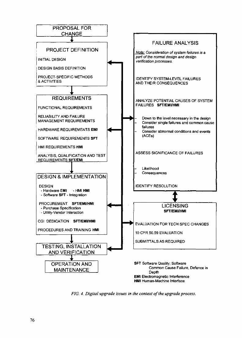
PROPOSAL FORCHANGE
PROJECT DEFINITION
INITIAL DESIGN
DESIGN BASIS DEFINITION
PROJECT-SPECIFIC METHODS& ACTIVITIES
IREQUIREMENTS
FUNCTIONAL REQUIREMENTS
RELIABILITY AND FAILUREMANAGEMENT REQUIREMENTS
HARDWARE REQUIREMENTS EMI
SOFTWARE REQUIREMENTS SFT
HMI REQUIREMENTS HMI
ANALYSIS, QUALIFICATION AND TESTREQUIREMENTS SFT/EMISFI7I
DESIGN & IMPLEMENTATION
DESIGN- Hardware EMI - HMI HMI- Software SFT - Integration
PROCUREMENT SFT/EMI/HMI- Purchase Specification- Utility-Vendor Interaction
CGI DEDICATION SFT/EMI/HMI
PROCEDURES AND TRAINING HMI
TESTING, INSTALLATIONAND VERIFICATION
OPERATION ANDMAINTENANCE
FAILURE ANALYSIS
Note: Consideration of system failures is apart of the normal design and designverification processes.
IDENTIFY SYSTEM-LEVEL FAILURESAND THEIR CONSEQUENCES
ANALYZE POTENTIAL CAUSES OF SYSTEMFAILURES SFT/EMI/HMI
Down to the level necessary in the designConsider single failures and common causefailuresConsider abnormal conditions and events(ACEs)
ASSESS SIGNIFICANCE OF FAILURES
LikelihoodConsequences
IDENTIFY RESOLUTION
LICENSINGSFT/EMI/HMI
EVALUATION FOR TECH SPEC CHANGES
10 CFR 50.59 EVALUATION
SUBMITTALS AS REQUIRED
SFT Software Quality; SoftwareCommon Cause Failure, Defence inDepth
EMI Electromagnetic InterferenceHMI Human-Machine Interface
FIG. 4. Digital upgrade issues in the context of the upgrade process.
76

System providers will divide these subsystems into smaller components as part of their designprocess. Each of these component parts should be individually tested, preferably at the manufacturer'spremises, before being integrated into a subsystem and subjected to formal factory acceptance tests.
As a minimum, the test procedure should contain the following items:
- identify items to be tested;- overall test approach;- test case specification;- specify the acceptance criteria;- specify the test environment;- specify a test sequence.
It is important that the version numbers of all the software and firmware modules are recordedat the start of the tests. The software should then be subjected to strict change control so that anychanges to the tested software can be identified and their impact analysed. Appropriate regressiontests must then be carried out to demonstrate that those parts of the system which have been affectedstill operate correctly.
Once the individual subsystems have been proven, it is necessary to integrate them with othernew subsystems and those parts of the old system which are being retained. This work will normallybe carried out at site and tests should be performed to confirm that all the interfaces are operatingcorrectly and to demonstrate that the system satisfies the operational requirements. It is important thatthe tests span the interfaces, particularly if the plant wiring, data acquisition subsystem and dataprocessing computers have been constructed from separate databases which must be manuallyaligned. In these cases, it is important to maintain strict change control on the various subsystems andto conduct testing to demonstrate their consistency.
Particular consideration should be given to the testing of any special interfaces where definitivetesting may only be possible on site. The testing strategy should be planned to cause minimumdisruption to the existing operational system and thought should be given to the use of operationalstandby systems or off-line test and development systems where these are available. For mostreactors, a full scale simulator facility will exist and consideration should be given to using it to assistwith the testing and commissioning activities.
Any invasive work such as the fitting of new transducers, or possibly the provision of extraconnection points to existing transducers should be carried out during planned plant outages whereverthis is possible. Care should be taken; however, to ensure that any new connections do not degrade theexisting systems which may still be operational. For example, some scanner subsystems may carryout loop continuity checks which would generate erroneous readings on any system connected inparallel. In such cases buffer circuits would need to be installed or alternatively isolation/changeoverlinks fitted so that plant connections could be switched from one system to the other.
The installation of signal buffering or isolation points during a plant outage would enable thereactor to return to power using the old I&C system. The new system can then be installed and testedwhilst the old system is still operational. This will enable the performance of the new system to bebenchmark against the old system under normal operating conditions. It is advisable to conduct thistesting in a location separate from the main control room and so minimize the impact on normal plantoperations. If modernization is being applied to several identical units, an alternate strategy could beto designate one unit as a test unit and to validate the new system on this unit before replicating it onother units.
Special consideration needs to be given to the testing of control systems and protection systemswhich drive plant outputs and cannot be coupled in parallel with the old system. For new or additional
77
protection systems, it is often feasible to run them initially as an advisory/alarm system alongside theexisting protection/reactor trip system. This will enable confidence to be gained in the response of thenew system to true faults and in the level of "spurious" faults which it generates. Similarly, theoutputs from control systems must be left disconnected while the old system is operationalNevertheless, it may still be possible to compare the output calculated by the new system with thatproduced by the old one.
11.3. DATA ACQUISITION SUBSYSTEMS
Prior to their installation at site, the subsystems should have been fully tested at themanufacturer's premises to demonstrate that they meet their specification. This should coverfunctional issues such as accuracy and linearity and also non-functional issues such as performanceand reliability.
The rate at which plant data acquisition subsystems can acquire data is often limited by signalconditioning/filtering facilities. For data acquisition subsystems tests should confirm that they areable to acquire analog data at the maximum specified rate with adjacent channel inputs set alternatelyto the maximum positive and maximum negative values specified.
Following the installation of the new subsystem at the site, it would be normal to test allexisting input signals from the new termination points. Where possible, signal injection tests shouldbe carried out from a point beyond which the old system has remained unchanged.
Where the new transducers have been fitted, the test should be carried out from the transducer.The objective of the testing is to prove that the new subsystem has been connected correctly and todemonstrate that the database and any signal conditioning are also correct. For analog signals thiscould be achieved by testing each signal at the top, bottom, and middle of its range and, wherepossible, checking the identity and value against the indications given by the old system. For digitalsignals the tests should be conducted with the input switched between true and false and again theresponse can be checked against the expected value or against the old system where this is possible.
Data input/output subsystems should have built in health monitoring and fault diagnosisfacilities. Tests should be conducted to demonstrate that these facilities are operating correctly andthat the correct actions, e.g., marking signals as invalid, are being performed by other parts of thesystem.
Most analog input subsystems will provide some form of signal continuity check andcommissioning checks should be conducted to prove the correct operation of this facility, forexample, by temporarily disconnecting the signal. Similarly it is prudent to provide "check channels"which are connected to pre-set inputs of known value. Forcing the "check channel" to an erroneousvalue should cause all the inputs on a particular input system to be marked invalid. The input/outputsubsystem should also contain a watchdog facility. This should cause the measurements to be markedinvalid if the data acquisition subsystems are not scanning the data correctly or are failing tocommunicate with the rest of the system. In the case of outputs a fail safe state should be defined andon detection of faults the system should, if possible, set all affected outputs to their fail safe state.Tests should be devised which emulate such faults and prove the correct operation of the faultmonitoring/mitigation facilities.
11.4. CONTROL SYSTEMS
The test procedure for new control systems should include before and after installation testsand commissioning tests. The activities of the different test phase are as follows:
78
- Before installation tests: To minimize on-site testing period, the test of the performance andenvironment for the new control systems should be performed as thoroughly as possible bysimulating the input parameters and measuring the output parameters of the system and the testresults approved before installation. The minimum test items are as follows:
evaluation of the required steady state and transient response for some operatingconditions;
- checking of the combined propagation delay from a change in a signal to results ofchange being received at an actuator;
checking the bumpless transfers between manual and automatic control;
checking the signal interface with other systems.
- After installation tests and commissioning tests: The integrated tests between new systemsand other systems should be performed, based on tests and calibration procedures developedduring design phase. The minimum test items are as follows:
- evaluation of the required steady-state and transient response for all operatingconditions;
- signal matching between new control systems and other systems (e.g. main controlroom, existing control systems, sensor, actuators, interrupt signals, and interlock withsafety system);
comparing the control input and output signals between new control systems and oldcontrol systems, in the case of parallel running of old and new system;
- checking the changeover mechanism between old and new control systems;
- checking any standby channel, in the case of using redundant control systems;
- checking the closed-loop response with respect to the reactor start up and a stepwiseincrease to full power;
- checking and calibration of the portion of analog inputs and outputs.
11.5. COMPUTER HARDWARE AND COMMUNICATION NETWORKS
In order to minimize the disruption to operational systems, exhaustive testing of thereplacement system should be conducted by the supplier before it is delivered to site. The equipmentshould, if possible, be assembled in its final configuration or as close to it as possible. This maypresent difficulties where the new system must integrate closely with existing I&C systems which arebeing retained. The factory testing will be greatly enhanced if examples of this existing equipmentcan be made available to the contractor during the development and testing phase. Tests should beconducted to demonstrate the equipment is capable of operating in the environment in which it is tobe installed. There is no doubt that variations in temperature, humidity, and electrical power suppliesare major contributors to the unreliability of computer based systems and every care should be takento maintain the environment as stable as possible. Nevertheless, changes in environmental conditionswill occur and the new systems should be proven to operate over the expected ranges of temperature,vibration, humidity, and electrical power supply for safety systems. It will also be necessary todemonstrate that the equipment can operate within seismic events of amplitude appropriate to theregion in which they are installed. IEEE 344 [64]gives guidance on seismic qualification.
79

Ideally EMC testing should be conducted with the equipment installed at site in its finalconfiguration (for more information see Section 9.2.4.1). Where the new equipment is to be located inexisting cubicles, there is no option but to complete the EMC testing at site. However, on replacementprojects the new equipment may be located adjacent to existing operational equipment which wouldbe susceptible to the EMC tests. It may; therefore, be preferable to conduct the tests prior to installingthe equipment at site and make allowances for any differences in the configuration. For example,additional holes, ventilation, cabling etc. may modify the electromagnetic characteristics of thecabinet.
The tests should demonstrate:
compatibility with emission requirements;
compatibility with susceptibility or immunity requirements.
To satisfy these two issues, the following steps should be applied:
- test the equipment to know its levels of EMI emission and susceptibility;
perform local tests or analysis to determine the EMI emission and susceptibility levels in theenvironment in which the equipment will be installed;
compare the equipment and the environment EMI values.
The environmental checks will normally be conducted with test software running on the systemdemonstrating that all the functionality operates correctly throughout the tests.
The same test software may also be suitable for conducting hardware performance tests. Theseshould demonstrate that all communication networks and interfaces to peripherals are able to operateat the specified rates. The tests should also monitor the processor loading with all the specifiedactivities running at the maximum rates. Particular attention should be paid to the loading of non-deterministic systems such as Ethernet where it is recommended that the maximum loading shouldnot exceed 10% of the bandwidth.
For distributed systems, checks must also be carried out to check for latency and transportdelays. A particular problem may be encountered with network protocols such as TCP/IP whereseveral messages may be held in a temporary store until the "communications packet" is full. If it isconfigured incorrectly, this may cause problems with "high speed" networks and with "heartbeat"type checks.
Computer based systems used in nuclear power plants should incorporate extensive selfchecking and error reporting mechanisms, which will minimize the incidence of unrevealed faults.This will include such provisions as software and hardware "watchdogs" and the monitoring of allperipheral devices. The complete testing of these facilities may not be possible without causingirreversible damage to some component parts. However, it should be possible to devise tests whichdisconnect each peripheral in turn and its associated power supplies. It may also be possible tosimulate faults through the use of test software or specialist equipment such as network analysers. Inall cases, the object of the test should be to demonstrate that the system is placed in a safe andpredictable state and that on removing the fault the system is returned to its operational state.
The health monitoring and error reporting functions may be linked to a main/standbychangeover mechanism. This may be a "manual" changeover whereby the error forces a shutdown ofthe operational system and provides an alarm to the operator who brings a standby system intoservice. Alternatively, the standby system may be brought into service "automatically" upon failure ofthe operational system. It should be recognized that the changeover mechanism can itself be a source
80

of errors and checks should be devised to confirm that a faulty system is correctly isolated and doesnot introduce errors or corruption onto the standby system.
11.6. SYSTEM SOFTWARE
It is anticipated that substantial proving of the system software will have been carried out priorto the system being installed at site. Since the system software consists of modules, those moduleshave to be tested first, and in the course of software integration, tests are performed after eachintegration step. This procedure is time consuming and costly. One possibility to reduce theseexpenses is to design a system (to the extent possible) from reusable software modules which can beconfigured and parameterized according to their envisaged application. Therefore systematic testingof these software modules can be performed "quasi once for ever" which complies with the strategyof testing reusable hardware modules from a traditional system (often referred to as type testing).
A specialty of the software modules (as compared to hardware) is the flexibility andconsequently the variety of reactions they show at the interfaces. In addition the software moduleshave "a virtual interface" with the hardware, because they are executed on the hardware. Therefore itis advisable to perform prior to the after installation tests a set of selected tests with a representativeamount of software modules (I&C functions) implemented on a representative hardwareconfiguration. The main aim of these tests is the proof of the (basic) system characteristics,independently of the specific design for a distinct plant. There are two main tasks, the proof of thecorrect operational behaviour, and the proof of the tolerable stress and failure behaviour.
For complete systems, exhaustive testing of the underlying system software may not befeasible. Software failures are systematic by nature. Therefore, it is possible that identical programversions in parallel trains will fail simultaneously and redundancy cannot in that case protect againstcommon mode failures.
It is probably impossible to produce and prove a software program to be totally free fromerrors. This implies that safety critical computerized applications must have some degree of errortolerance, and a certain degree of diversity must be provided for critical functions in order to preventcommon mode failures from leading to severe failures.
As no commonly accepted method exists for showing that reliability requirements have beenreached, different practices must be used in order to reduce the uncertainty in reliability. Thesemethods are deterministic, probabilistic, and experience based. In IEC-880 (1986) Appendix E [24] itis possible to find more detailed information.
Deterministic based methods incorporate the use of standards, quality assurance programmes,and different types of test programmes. They also seek evidence of the supplier's developmentprocess and management systems for reporting and correcting errors. Commercial vendors ofequipment containing software or firmware often have not completed a V&V programme at the levelof the requirements and standards referred to above. Thus, the purchaser must ensure that theappropriate activities are undertaken to develop an equivalent level of confidence in the commercialgrade item's software. This is done through a process of commercial grade item dedication. The dutiesfor performing commercial dedication of equipment should be specified. The purchaser may needaccess to vendor's design documents, test data, and information to evaluate the vendor's designprocess used for software. The software design should be compared to the applicable design criteriafor nuclear qualified equipment. Differences may be compensated for by other factors such asdocumented operating experience in a similar application, or by additional V&V or testing performed.
Experience data, results of additional testing that is performed as part of the upgrade design andverification processes, information obtained on the design development, and other analysis asappropriate should be combined to judge the acceptability of the commercial grade item.
81

11.7. CONFIGURATION LEVEL SOFTWARE/DATA
Configuration level software/data are the software/data structures which are specific to aparticular project. They can include operating formats, database identifiers and threshold levels, alarmconditioning, and interfaces to existing equipment. Because a replacement system must fit with theexisting equipment, the amount of "project specific" software is likely to be higher than on newprojects and this needs to be addressed when devising commissioning plans.
Perhaps the most important aspect of a replacement system is the database. Where only part ofa system has been replaced, it is likely that the database for the old system and that for the new partwill be constructed separately. Strict change control needs to be imposed on the two databases whichin an ideal world should be merged into one. Tests should be devised which bridge the interfacesbetween the replacement system and the rest of the plant. These should demonstrate that the newsystem database is correct and consistent both internally and also with the existing plant. Manycommercially available systems provide CAD facilities to assist in the production of operationalformats. The formats should have been reviewed against functional requirements and ergonomicstandard prior to the commissioning phase. The main objective of the commissioning phase is todemonstrate that the formats are linked to the correct database items and are being updated at therequired rate. It may be possible to use test software, or better still signal injection, to prove that thedata is being displayed correctly. If test software is used, then care should be taken to ensure that it isindependent of any CAD software used to produce the formats. Otherwise a common mode failurecould result.
Some computer based systems have sophisticated alarm conditioning logic or other plantspecific pieces of software. These may have been developed and configured over many years of plantoperation and need to be preserved in the replacement system. Conducting exhaustive tests todemonstrate the faithfulness of the replacement may not be feasible. In this case, consideration shouldbe given to the development of "high integrity" "translation software" which will automaticallyconvert the application from the old system to the new. In this case, the exhaustive tests can bereplaced by sample checks to prove that there are no systematic errors in the translation process.Again, common mode errors are a likely source of failure and these should be guarded against at allstages in the process.
The application software/data may also include special interfaces to link the new system tothose parts of the old system which are remaining unchanged. The main challenge in developing suchsoftware is often the lack of a clear interface definition. This will also present a problem in testing thesoftware and the only sure way is to gain access to the old system without effecting plant operation.This could be achieved by use of a spare system or existing simulator facilities. If neither of theseoptions is available then it may be necessary to conduct the tests during a plant outage. As with thedatabase, the tests must bridge the interface between the old and new systems. Simply testing the newsystem against a written specification could leave too many potential errors unrevealed.
11.8. HUMAN-MACHINE INTERFACE
Workstations are often used to provide the interface between new I&C systems and humanoperators. All the considerations which were applied to the testing of hardware and software for thedata processing layer will also apply here.
In addition the HMI should be assessed against the ergonomic requirements to presentinformation to the operating staff in a clear, unambiguous and timely manner. It is suggested that theuse of the training simulator may be suitable for performing the ergonomic assessment.
It is important to ensure that the data presented to the operator is being continually refreshed atan appropriate rate and specific tests should be conducted to confirm this. In many systems a dynamicsymbol is placed in the corner of each display to indicate that the display is updating. Such a symbol
82

should be generated from the same source as the data being displayed, so that it monitors the health ofthe whole data path and not just the health of the workstation.
11.9. LINKS TO THE OFF-LINE SYSTEMS
The real time I&C systems will often provide information to off-line support systems whichthemselves may or may not be subject to an upgrade. In either case it will be necessary to provide thecorrect data interface from the upgraded I&C systems. Normally the off-line systems will not be realtime and it should be possible to temporarily connect to the new system and prove the interface priorto the main changeover. Tests should be conducted to demonstrate that actions/faults on the off-linesystem do not feedback onto the I&C system and adversely affect its performance.
11.10. INTEGRATED TESTING
Once all the subsystems have been tested, there is still a need for complete end-to-end tests ofthe system and, where possible, this should include the parts of the old system which interface to thenew ones of the subsystem. If the checks have been thorough, then sample checks may be adequate atthis stage.
Tests should be carried out to confirm that the required system performance has been achievedand to confirm the operation of any facility that could not be tested during the manufacturer's factoryacceptance test.
11.11. PARALLEL RUNNING
On new projects, the I&C system is often available ahead of the rest of the plant and is usedduring plant test and commissioning. This may take place over an extended period of time duringwhich increased confidence is gained in the I&C system. On replacement projects, plant downtime isusually kept to a minimum and other means must be found for building confidence in the replacementI&C system.
This may be achieved by retaining the old system for a period of time and running thereplacement system alongside it. The parallel running tests should be planned as part of the siteacceptance tests. Where possible tests should be created which will stimulate plant inputs andincorporate a range of operational activities in order to provide a realistic test of the new system. Caremust be taken to ensure that the operational state of the old system is not compromised. Bufferamplifiers and one way data links may be required to feed plant data into the new system during theparallel running period. The response of the new system can then be compared with the old one for avariety of operational conditions. Allowance will need to be made for latency, data skew, andsampling errors when comparing the two systems, but the responses should be close enough to allowa meaningful comparison. This approach can be used to provide confidence in the reliability of thenew system and the correctness of databases, formats, alarm levels, alarm logic, and otherapplications software/data.
Once confidence has been gained in the new system, changeover can take place between theold system and the replacement. The exact method of changeover will differ for each project.
The state of plant at changeover is also important and for some projects it may be safer tochange systems with the plant stable and at power, since this state may place the least demand on thenew system. At all times during system changeover, it is important that operating staff are aware ofthe exact state of the plant and there is a clear definition of which parts of the I&C system areoperational and which are being commissioned.
83

11.12. FULL SCALE SIMULATOR
On most plants, a full scale simulator is available for the training of operating staff. Thissimulator will need to be updated to reflect the changes to the operational systems and be used for theretraining of the operators. It can also be used for verification and validation during the designprocess and for final testing of the modifications. Two areas should be evaluated. One is the HMI andthe other is the critical I&C functions. The use of the full scale simulator for these purposes must beplanned early in a modernization project.
Before starting the detailed design of the HMI, a prototype can be connected to the simulator.Operators and designers can work together to evaluate ideas and proposals and discuss suitabledesigns. This can be repeated with the final version of the equipment before it is installed into theplant. Some detailed design work such as for designing display screens can also be done then. Thevalidation of the final design can be used for retraining personnel before the control room is modified.It is recommended that the modifications are installed in the simulator as a permanent part of thesimulator. Simulators contain programs for all I&C functions or systems. Dependent on the softwarestructure and the input and output facilities, I&C functions can be bypassed and replaced by systemsconnected to the simulator. Critical systems for protection and plant control can be verified byconnecting the actual modified equipment to the simulator and using the plant process simulation fortesting. Similar methods have been used for validation of control systems where the process model isbuilt into the control equipment. The experience with this method are very positive and have savedconsiderable time during commissioning after installation in the plant. It is, therefore recommendedto use the full scale simulator for this method.
11.13. SPECIFIC CHECKS AGAINST SAFETY PRINCIPLES
It is good practice to review the commitments which have been made in setting down the safetyprinciples for an I&C upgrade project. Before putting the new system into operation tests should beconducted to demonstrate that those commitments have been met. Typical commitments for a controland monitoring system could be as follows:
- Any automatic testing function in accordance with the old technical specification (in PWRcase, technical specification in Safety Analysis Report) should be tested to verify that there isno impact on the integrity of safety functions, before commissioning.
- Failure of the control system does not move the reactor to a more unsafe state.
A single credible failure of the non-safety control system does not place a demand on thereactor protection system.
All controls, alarms and indications required for safe operation are located in the MCR.
Instruments have adequate accuracy during normal operating conditions.
- Instruments do not saturate under fault conditions.
Removal/disconnection of items for testing does not cause signals or plant to change in amanner which is detrimental to safety
Operation following power supply interruptions is predictable and safe.
- Alarm information is presented in a manner which can be assimilated.
Alarms are not capable of being reset until the initiating parameter is reset.
84

Pre and post incident records are provided for selected safety related parameters.
All software is under configuration control.
- The software contains self checks and takes defined safe action on detection of a fault.
Corruption of program or fixed data is detected under normal operation.
11.14. DOCUMENTATION
Documentation has already been discussed in Section 7.7. It is desirable that operational andmaintenance documentation is available during system commissioning. The commissioning testsshould refer to these documents wherever possible so that they can be validated against the expectedsystem behaviour.
The installation and commissioning test results should be documented for future reference bythe utility and for verification by the regulatory body. The documentation should include as aminimum the following:
verification that new systems and their installation meets code and standards that werespecified in the design of the systems;
overall functional performance requirements of the new system have been met;
calculated range and rate of change of the sensed variables have been verified by testing;
bench test results, final test results, functional performance and other special requirements ofthe control systems;
test operation report;
- maintenance and regular test programme;
- operator training programme.
12. CONCLUSIONS
The five major conclusions and their subconclusions of this report are given here.
1. Define a global vision. This should be a strategic plan covering the whole of the plant I&C forthe remaining plant life.
1.1. A global vision of the overall future I&C configuration needs to be defined at thebeginning of the modernization activities in order to identify the best way to do themodernization projects to achieve the desired end goal for the plant's I&C systems.
1.2. A life-cycle management programme should be developed to evaluate the need tomodernize an I&C system in the context of the goals, requirements, and constraints ofthe entire plant.
1.3. The vision and modernization plans need to be flexible and expandable to allow forchanging conditions such as goals, constraints, requirements, and technology. Theyshould be reviewed periodically and revised as needed.
85

1.4. Each modernization project needs to be an integral part of the global vision and life-cycle management plan and should not be done in isolation.
1.5. External requirements that effect I&C modernization; such as regulatory requirements,commitments to the public and regulatory bodies, and power needs; must be identifiedand taken into account in the life-cycle management programme.
1.6. Utility defined requirements that effect I&C modernization; such as functional,physical, economical, and human factors; must be identified and taken into account inthe life-cycle management programme.
1.7. I&C systems can be modernized in an incremental manner following the plant vision aswell as being done in one massive project.
2. Develop standards and plans. Available standards and guidance documents should be reviewedand tailored to match the utility's specific circumstances.
2.1. The utility should define plant-specific standards and guidelines to be used for I&Cmodernization projects to address issues such as hardware qualification, softwareverification and validation, requirements specification, and failure analysis.
2.2. The utility should develop detailed modernization or maintenance plans as appropriatefor each I&C system considered in the life-cycle management programme.
2.3. Modernization projects should carefully consider international standards andrequirements to select those applicable.
2.4. An integrated approach to modernization of I&C systems is needed to maintainconsistency with existing systems and to facilitate future modernization projects tomaximize the effectiveness of new and modernized systems in the entire plant. I&Cmodernization projects should not be done in a stand-alone manner.
2.5. When modernization is performed in an incremental manner, a long term migration pathneeds to be developed to ensure that each modernization is performed consistently withthe overall vision.
3. Capture the requirements. Significant effort is often required to produce up to datedocumentation of the safety role and functional role of old I&C systems. In setting down thesystem requirements, account should be taken of modern standards.
3.1. The utility should interface with the regulatory agency early in the project formodernization projects of safety and safety related systems to ensure that safetyconcerns are addressed.
3.2. A baseline description and verified, up-to-date documentation is needed for each of theI&C systems to be considered for modernization.
3.3. When it is not practical to meet a current standard or requirement in an existing plant,justification should be provided using methods such as probabilistic tools or engineeringjudgment.
3.4. Accurate, up-to-date documentation for each existing, replaced, upgraded, and new I&Csystem should be maintained throughout the life of the system.
86

3.5. A project internal QA document should be produced to govern the modernizationproject.
4. Take advantage of new technology. In a modernization project it is often beneficial to add newfunctionality rather than only doing like-for-like changes.
4.1. When a modernization programme is being considered, potential improvements that arepossible with modern technology should be evaluated. This should include informationhandling, to increase functionality, to increase performance, to improve availability, toreduce costs, to enhance safety, to improve working methods, and to improveorganizational functions.
4.2. Office automation and modem data handling systems support an easy transfer ofinformation between various systems to provide valuable support in the control roomand in other tasks.
4.3. A communications infrastructure should be installed early in the modernizationprogramme to allow integration of systems and information throughout the programme.
5. Plan and monitor your modernization project. There are many interdependences which shouldbe taken into account and it is necessary to be aware of possible problems before they arise.
5.1. Advance planning and as much advance work as possible should be done before theoutage so that the modernization can be done without extending the plant outage.
5.2. A close relationship between the utility and contractor is advantageous efficientmodernization activities.
5.3. Proposed control room solutions should be reviewed carefully to assess changes in thebasic operational philosophy. The detailed design should be submitted to a humanfactors review including shift representatives.
5.4. It is advantageous to use a full scope simulator to verify the operability of the newsystem before implementing it.
5.5. Training, procedures and documentation must be updated rigorously to include themodernized systems.
NEXT PAGE(S)left BLANK
87
Appendix A
EQUIPMENT TECHNOLOGY DEFINITIONS
In order to identify the performance of new equipment, it will be necessary to understand thenature of the different technologies and the implications the choice of technology has on achievingthe required functionality and on completing a safety justification. This is particularly necessary giventhe great differences in the characteristics and performance of different types of technology that isavailable or under development. These include:
relays and other electromechanical components, analog equipment, digital equipment withhardwired logic or embedded software ("firmware");
free programmable digital equipment as PLCs and process computers;
The typical characteristics of the above mentioned technology are described below.
A.l. RELAY AND OTHER HARDWIRED EQUIPMENT
(a) Relays
This is an electromagnetic device for switching of analog and binary output signals. The inputfor switching is a binary signal. The relay is a component. System equipment must be built by anextensive wiring between many relays.
(b) Analog equipment
Solid state equipment is based on transistor technology. It can be used for both binary and analogsignals. Different design methods are possible as described here:
discrete components where a function is designed by using individual components astransistors, resistors, capacitors which are together on circuit boards;
integrated chips where many transistors and sometimes resistors or capacitors are integrated toperform a certain function, these chips are put together on circuit boards;
devices where discrete components or integrated chips are combined together in some type ofhousing to perform a more stand alone, integrated function;
electronic systems which are a product family containing many different standard cards with allfunctions which are necessary for process I&C. These cards are combined within a housing todesign a complete I&C system.
(c) Field programmable gate arrays (FPGA)
This is chip for binary input and output signals and is custom designed for a particularapplication. The logical relations of "and" and "or" between the signals can be defined by on theFPGA. A special tool will burn in the logic operations in a permanent manner so they cannot bemodified. Modifications can only be done later by burning new chips.
(d) Application specific integrated circuit (ASIC)
This is chip which can contain both logic and analog functions. It is designed especially for anapplication and can be mass produced. It cannot be modified afterwards.
89

A.2. FREE PROGRAMMABLE EQUIPMENT
Free programmable technology is characterized by the fact that functions are carried in a timesequence. The sequence is controlled by counters or a operating system. Functions are performed withsoftware. Different types are:
(a) Programmable logic devices (PLD)
A programmable logic device is micro processor based in order to carry out a well definedfunction. It is a stand alone apparatus and can be reprogrammed to meet different options oradjustments for the specified function.
(b) Programmable logic controllers (PLC)
A PLC is the microprocessor based version of the FPGA. Logic relations between binary inputsand outputs are defined by software. Often the logic can be selected from a library by using standardtools. The logic can easily be reprogrammed afterwards.
(c) Configurable electronic equipment
Programmable electronic equipment can be compared with the solid state electronic systemwhere you configure a application by using different kind of standard modules from a standardpackage which can be purchased on the market. It is often called "Programmable Electronic System".(PES) Such package contains all necessary standard hardware and software for process I&Cincluding:
process inputs and outputs;and other signal treatment functions;
- graphical human logic machine interfaces;communications.
Integration of the standard hardware and software modules into an application is done in a easyway through the use of standard tools. No special programming knowledge is required.. Normally thePES cannot perform complicated calculations which are necessary for important computerizedsupport systems. Several type of configurations can be designed in the range between totallydecentralized and centralized
(d) General purpose minicomputers
A minicomputer is a flexible and general purpose machine. It is normally not provided withstandard software and hardware modules which are necessary for I&C functions. Such functions mustbe purchased separately or must be designed/programmed by the application engineers.Minicomputers can therefore be used for such functions, which cannot be configured by standardsoftware modules from the PES, such as:
- complex arithmetic and logic processing;mass storage of historical data;
- recording of plant performances;alarm analysis.
90
Appendix B
RECOVERY OF OLD REQUIREMENTS EXAMPLE
Example: Recovery of old requirements for a reactor protection system (RPS)
(1) Safety requirements
(a) The protection system should be designed:
- to automatically initiate the operation of appropriate systems, including thereactivity control systems, to assure that specified acceptable fuel design limits arenot exceeded as a result of transients;
- to sense accident conditions and to initiate the operation of systems andcomponents important to safety;
(b) Protection systems should meet the requirements set forth in applicable EEEE or EECguides and standards as IEEE 279 [65], IEEE 603 [66], IEEE 7-4.3.2-1993 [30], or EEC880 [24].
(2) Licensing limitations
Some of the limitations are:
- Reliability evaluations are nearly impossible for software;- The more complex are the functions the more complex is the verification and validation.
An important issue is the policy of the regulatory body about the application of modemrequirements for modernization of old plants. For this reason a careful analysis must be madecomparing the originally requirements with new ones
(3) Major functions
(a) Plant protection system functions:
- Reactor protection system function;- Engineered safety features actuation function.
(b) Reactor trip parameters:
- Variable overpower;High LPD;Low DNBR;
- High log power level;- High pressurizer pressure;- Low pressurizer pressure;- High steam generator water level;- Low steam generator water level;- Low steam generator pressure;- High containment pressure;- Low reactor coolant flow;- Manual.
91

(c) Engineered safety features actuation signals:
- Containment isolation actuation signal;- Containment spray actuation signal;- Safety injection actuation signal;- Aux. feed water actuation signal;- Recirculation actuation signal;- Main steam isolation signal.
(d) Plant protection system design requirements:
- Four independent measure channels;- System actuation on 2/4 coincidence of selected plant variables;- coincidence logic with one channel being out of service;- Manual reset necessary once actuation has been initiated;- Manual actuation independent of automated trip;- System can be tested with the plant in shutdown or operating mode.
(4) Inputs/outputs
(a) Inputs:
- Inputs from engineered safety features auxiliary relay cabinets;- Inputs from process instrumentation cabinet;- Inputs from remote shutdown panel;- Inputs from ex-core nuclear flux monitoring system, safety channel drawer;- Inputs from auxiliary protective cabinet;
Inputs from reactor trip switch gear system;- Inputs from vital bus power supply system.
(b) Outputs:
- Outputs to plant data acquisition system;- Outputs to engineered safety features auxiliary relay cabinets;- Outputs to process instrumentation cabinet;- Outputs to remote shutdown panel;- Outputs to reactor trip switch gear system;- Outputs to CEA element drive mechanism control system auxiliary cabinet;- Outputs to plant annunciation system;- Outputs to auxiliary protective cabinet;- Outputs to ex-core nuclear flux monitoring system, safety channel drawer.
(5) Interfacing systems
(a) Process instrumentation cabinet;(b) Engineered safety features auxiliary relay cabinets;(c) Remote shutdown panel;(d) Ex-core nuclear flux monitoring system, safety channel drawer;(e) Auxiliary protective cabinet;(f) Reactor trip switch gear system;(g) Vital bus power supply system;(h) Plant data acquisition system;(I) CEA element drive mechanism control system auxiliary cabinet;(j) Plant annunciation system.
92

(6) Operating experience
(a) Periodic tests and component obsolescence:
- Manual periodic testing with complicated test procedures has required substantialmanpower resources and has contributed to human errors by the maintenance staff;
- Component obsolescence has increased the required maintenance work.
(b) Information navigation:
It is difficult for operator and/or maintenance people to provide sufficient andsummarized information of system status during complicated operation and maintenancesituations.
(7) Challenges
The most important challenges are to:
- use the new features of the digital technology to improve safety and availability;
- improve the display of information in the control room;- integrate control and maintenance activities;- combine old and new technology;- replace equipment without extending outages.
NEXT PAGEJS)
93

REFERENCES
[I] ELECTRIC POWER RESEARCH INSTITUTE, Instrumentation and Control Life CycleManagement Plan Methodology, EPRITR-105555, Vols. 1&2 (1995).
[2] ELECTRIC POWER RESEARCH INSTITUTE, Requirements Engineering for DigitalUpgrades, EPRI TR-108831 (1997).
[3] ELECTRIC POWER RESEARCH INSTITUTE, Guideline on Licensing Digital Upgrades,EPRI TR-102348 (1993).
[4] ELECTRIC POWER RESEARCH INSTITUTE, Plant Communications and ComputingArchitecture Plan Methodology, EPRI TR-102306, Vols. 1&2 (1993).
[5] ELECTRIC POWER RESEARCH INSTITUTE, Plant Communications and ComputingArchitecture Plan Methodology Revision 1, EPRI TR-104129, Vols. 1&2 (1994).
[6] ELECTRIC POWER RESEARCH INSTITUTE, Handbook of Verification and Validation forDigital Systems, EPRI TR-103291, Vols. 1-3 (1994).
[7] ELECTRIC POWER RESEARCH INSTITUTE, Guidelines for the Verification andValidation of Expert System Software and Conventional Software, EPRI TR-103331, Vols. 1-8 (1995).
[8] ELECTRIC POWER RESEARCH INSTITUTE, Verification and Validation Guidelines forHigh Integrity Systems, EPRI TR-103916, Vols. 1&2 (1995).
[9] ELECTRIC POWER RESEARCH INSTITUTE, Software Fault Reduction Using Computer-Aided Software Engineering (CASE) Tools, EPRI TR-105989, Vols. 1&2 (1995).
[10] ELECTRIC POWER RESEARCH INSTITUTE, Guidelines for Electromagnetic InterferenceTesting in Power Plants, EPRI TR-102323-R1 (1996).
[II] ELECTRIC POWER RESEARCH INSTITUTE, Handbook for ElectromagneticCompatibility of Digital Equipment in Power Plants, EPRI TR-102400, Vols. 1&2 (1994).
[12] ELECTRIC POWER RESEARCH INSTITUTE, Abnormal Conditions and Events Analysisfor Instrumentation and Control Systems, EPRI TR-104595, Vols. 1&2 (1996).
[13] ELECTRIC POWER RESEARCH INSTITUTE, Guideline for the Utilization of CommercialGrade Items in Nuclear Safety Related Applications (NCIG-07), EPRI NP-5652 (1988).
[14] ELECTRIC POWER RESEARCH INSTITUTE, Supplemental Guidance for the Applicationof EPRI NP-5652 on the Utilization of Commercial Grade Items, EPRI TR-102260 (1994).
[15] ELECTRIC POWER RESEARCH INSTITUTE, Guideline on Evaluation and Acceptance ofCommercial Grade Digital Equipment for Nuclear Safety Applications, EPRI TR-106439(1996).
[16] ELECTRIC POWER RESEARCH INSTITUTE, Evaluating Commercial Digital Equipmentfor High-Integrity Applications: A Supplement to EPRI Report TR-106439, EPRI TR-107339(1997).
[17] ELECTRIC POWER RESEARCH INSTITUTE, Generic Requirements Specification forQualifying a Commercially Available PLC for Safety Related Applications in Nuclear PowerPlants, EPRI TR-107330 (1996).
[18] ELECTRIC POWER RESEARCH INSTITUTE, I&C Upgrades for Nuclear Plants DeskReference 1997, EPRI TR-107980 (1997).
[19] ELECTRIC POWER RESEARCH INSTITUTE, Plant-Wide Integrated EnvironmentDistributed on Workstations (Plant-Window) System Functional Requirements, EPRI TR-104756(1996).
[20] ELECTRIC POWER RESEARCH INSTITUTE, Plant Process Computer UpgradeGuidelines, EPRI TR-101566, Vols. 1-3 (1992).
[21] ELECTRIC POWER RESEARCH INSTITUTE, Application of a Cost-Benefit AnalysisMethodology to Nuclear I&C System Upgrades, EPRI TR-101984 (1992).
[22] ELECTRIC POWER RESEARCH INSTITUTE, Instrumentation and Control UpgradeEvaluation Methodology, EPRI TR-104963, Vols. 1&2 (1996).
[23] ELECTRIC POWER RESEARCH INSTITUTE, Instrumentation and Control SystemMaintenance Plan Methodology, EPRI TR-106029 (1996).
95

[24] INTERNATIONAL ELECTROTECHNICAL COMMISSION, Software for Computers in theSafety Systems of Nuclear Power Stations, IEC-880, Geneva (1986).
[25] INTERNATIONAL ORGANIZATION FOR STANDARDIZATION, ISO-9000 Standardseries: Quality Management and Quality Assurance Standards, ISO, Geneva (1990).
[26] INTERNATIONAL ORGANIZATION FOR STANDARDIZATION, ISO-9000 Standardseries: Quality Management and Quality Assurance Standards, Part 3: Guidelines for theApplication of ISO 9001 to the Development, Supply and Maintenance of Software, ISO,Geneva (1990).
[27] INTERNATIONAL ATOMIC ENERGY AGENCY, Verification and Validation of SoftwareRelated to Nuclear Power Plant Control and Instrumentation (in preparation).
[28] INSTITUTE OF ELECTRICAL AND ELECTRONICS ENGINEERS, Standard for SoftwareQuality Assurance Plans, ANSI/IEEE 730-1989, IEEE, Piscataway, NJ (1989).
[29] INSTITUTE OF ELECTRICAL AND ELECTRONICS ENGINEERS, Standard for SoftwareVerification and Validation Plans, ANSI/IEEE Std 1012-1986, IEEE, Piscataway, NJ (1986).
[30] INSTITUTE OF ELECTRICAL AND ELECTRONICS ENGINEERS, IEEE StandardCriteria for Digital Computers in Safety Systems of Nuclear Power Generating Stations, IEEEStd 7-4.3.2-1993, IEEE, Piscataway, NJ (1993).
[31] INSTITUTE OF ELECTRICAL AND ELECTRONICS ENGINEERS, IEEE Standard forSoftware Configuration Management Plans, ANSI/IEEE Std 828-1990, IEEE, Piscataway, NJ(1990).
[32] INSTITUTE OF ELECTRICAL AND ELECTRONICS ENGINEERS, IEEE Guide toSoftware Configuration Management, ANSI/IEEE Std 1042-1987, IEEE, Piscataway, NJ(1987).
[33] INTERNATIONAL ATOMIC ENERGY AGENCY, Modern Instrumentation and Control forNuclear Power Plants, A Guidebook (in preparation).
[34] INTERNATIONAL ATOMIC ENERGY AGENCY, A Common Base for Judging the Safetyof Nuclear Power Plants Built to Earlier Standards, Safety Series No.8, IAEA, Vienna (1995).
[35] NUCLEAR REGULATORY COMMISSION, Method for Performing Diversity and Defense-in-depth Analyses of Reactor Protection Systems, Rep. NUREG/CR-6303 (1994).
[36] INTERNATIONAL ELECTROTECHNICAL COMMISSION, Analysis Techniques forSystem Reliability-Procedure for Failure Mode and Effects Analysis (FMEA), IEC-812,Geneva (1985).
[37] INTERNATIONAL ATOMIC ENERGY AGENCY, Safety Assessment of ComputerizedControl and Protection Systems, IAEA-TECDOC-780, Vienna (19945).
[38] INTERNATIONAL ATOMIC ENERGY AGENCY, Reliability of Computerized SafetySystems at Nuclear Power Plants, IAEA-TECDOC-790, Vienna (1994).
[39] INTERNATIONAL ATOMIC ENERGY AGENCY, Probabilistic Safety Assessment, AReport by the International Nuclear Safety Advisory Group, Safety Series No. 6, IAEA,Vienna (1992).
[40] INTERNATIONAL ATOMIC ENERGY AGENCY, Case Study on the Use of PSA methods:Assessment of Technical Specifications for the Reactor Protection System Instrumentation,IAEA-TECDOC-669, Vienna (1992).
[41] INTERNATIONAL ELECTROTECHNICAL COMMISSION, Fault Tree Analysis (VTA),IEC-1025, Geneva (1990).
[42] INTERNATIONAL ELECTROTECHNICAL COMMISSION, Analysis Techniques forDependability-Reliability Block Diagram Method, IEC-1078, Geneva (1991).
[43] INTERNATIONAL ELECTROTECHNICAL COMMISSION, International ElectrotechnicalVocabulary: Chapter 191: Dependability and quality of service, IEC 50 (1991).
[44] EUR, European Utility Requirements for Nuclear Power Plants, Draft Nov. 1996(Communication from P. van Gemst).
[45] INTERNATIONAL ATOMIC ENERGY AGENCY, Code on the Safety of Nuclear PowerPlants: Design, Safety Series No. 50-C-D, IAEA, Vienna (1988).
[46] INTERNATIONAL ATOMIC ENERGY AGENCY, Protection System and Related Featuresin Nuclear Power Plants, A Safety Guide, Safety Series No. 50-SG-D3, IAEA, Vienna (1980).
96

[47] INTERNATIONAL ATOMIC ENERGY AGENCY, Safety-Related Instrumentation AndControl Systems For Nuclear Power Plants, A Safety Guide, Safety Series No. 50-SG-D8,IAEA, Vienna (1984).
[48] INTERNATIONAL ELECTROTECHNICAL COMMISSION, Supplementary Control Pointsfor Reactor Shutdown Without Access to the Main Control Room, IEC-965 (1989).
[49] INTERNATIONAL ELECTROTECHNICAL COMMISSION, Programmed DigitalComputers Important to Safety for Nuclear Power Stations, IEC-987 (1989).
[50] INTERNATIONAL ELECTROTECHNICAL COMMISSION, Design for Control Rooms ofNuclear Power Plants, IEC-964, Geneva (1989).
[51] INTERNATIONAL ATOMIC ENERGY AGENCY, Balancing Automation and HumanAction in Nuclear Power Plants (Proc. Symp. Munich, 1990), IAEA, Vienna (1991).
[52] INTERNATIONAL ATOMIC ENERGY AGENCY, The Role of Automation and Humans inNuclear Power Plants, IAEA-TECDOC-668, Vienna (1992).
[53] US NUCLEAR REGULATORY COMMISSION, Human Factors Engineering ProgramReview Model, NUREG-0711 (1994).
[54] US NUCLEAR REGULATORY COMMISSION, Guidelines for Control Room Design,NUREG-0700 (1981).
[55] INTERNATIONAL ATOMIC ENERGY AGENCY, Computerized Support Systems inNuclear Power Plants, IAEA-TECDOC-912, IAEA, Vienna (1996).
[56] INTERNATIONAL ELECTROTECHNICAL COMMISSION, Electro-magneticCompatibility (EMC), IEC-1000, Part 1: General, Part 2: Environment, Part 4: Testing andmeasuring techniques (1992-1993).
[57] INSTITUTE OF ELECTRICAL AND ELECTRONICS ENGINEERS, IEEE Standard forQualifying Class IE Equipment for Nuclear Power Generating Stations, IEEE Std 323-1983,IEEE, Piscataway, NJ (1983).
[58] US NUCLEAR REGULATORY COMMISSION, Verification, Validation, Reviews, andAudits for Digital Computer Software Used in Safety Systems of Nuclear Power Plants,USNRC Regulatory Guide 1.168, August (1997).
[59] US NUCLEAR REGULATORY COMMISSION, Configuration Management Plans forDigital Computer Software Used in Safety Systems of Nuclear Power Plants, USNRCRegulatory Guide 1.169, August (1997).
[60] US NUCLEAR REGULATORY COMMISSION, Software Test Documentation for DigitalComputer Software Used in Safety Systems of Nuclear Power Plants, USNRC RegulatoryGuide 1.170, August (1997).
[61] US NUCLEAR REGULATORY COMMISSION, Software Unit Testing for DigitalComputer Software Used in Safety Systems of Nuclear Power Plants, USNRC RegulatoryGuide 1.171, August (1997).
[62] US NUCLEAR REGULATORY COMMISSION, Software Requirements Specifications forDigital Computer Software Used in Safety Systems of Nuclear Power Plants, USNRCRegulatory Guide 1.172, August (1997).
[63] US NUCLEAR REGULATORY COMMISSION, Developing Software Life Cycle Processesfor Digital Computer Software Used in Safety Systems of Nuclear Power Plants, USNRCRegulatory Guide 1.173, August (1997).
[64] INSTITUTE OF ELECTRICAL AND ELECTRONICS ENGINEERS, IEEE RecommendedPractice for Seismic Qualification of Class IE Equipment for Nuclear Power GeneratingStations, IEEE Std 344-1975, IEEE, Piscataway, NJ (1975).
[65] INSTITUTE OF ELECTRICAL AND ELECTRONICS ENGINEERS, IEEE Criteria forProtection Systems in -Nuclear Power Generating Stations, IEEE Std 279-1971, IEEE,Piscataway, NJ (1971).
[66] INSTITUTE OF ELECTRICAL AND ELECTRONICS ENGINEERS, IEEE StandardCriteria for Safety Systems for Nuclear Power Generating Stations, IEEE Std 603-1993,IEEE, Piscataway, NJ (1993).
NEXT PAQE(S)left BLANK

Annex
COUNTRY REPORTS
NEXT PAQE(S)••ft BLANK
99

NPP I&C SYSTEM MODERNIZATIONS IN THE XA9847292CZECH REPUBLICThe NPP Dukovany example
P.KRSState Office for Nuclear Safety,Prague, Czech Republic
Abstract
There are four units of WWER 440/213 type reactors under operation at Nuclear Power Plant Dukovanysite in the Czech Republic. The EEZ utility has decided to include upgrade of existing Instrumentation &Control (I&C) systems as one of the most significant parts of a larger scale modernization project. The originalI&C systems designed in the late 70's and early 80's with analogue equipment and relays will be subjected to anintegrated modernization programme developed to replace obsolete equipment, to balance operational andmaintenance costs, to improve performance and to enhance plant safety. To achieve this objective within nextdecade, the utility has already started preparatory phase of the overall modernization project, includinganalytical and planning activities related to the I&C part.
1. INTRODUCTION
There are four units of WWER 440/213 type reactors under operation at Nuclear Power Plant(NPP) Dukovany site and two units of WWER 1000/320 type reactors under construction at NPPTemelin site in the Czech Republic. Both of the nuclear power plants are operated by the largestCzech utility Eeske Energeticke Zavody (EEZ).
For the Dukovany units, the EEZ utility has decided to include upgrade of existingInstrumentation & Control (I&C) systems as one of the most significant parts of a larger scalemodernization project. The original I&C systems designed in the late 70's and early 80's withanalogue equipment and relays will be subjected to an integrated modernization programmedeveloped to replace obsolete equipment, to balance operational and maintenance costs, to improveperformance and to enhance plant safety. To achieve this objective within next decade, the utility hasalready started preparatory phase of the overall modernization project, including analytical andplanning activities related to the I&C part.
To enhance the level of safety and availability of the future operation, the EEZ utility hasdecided to introduce significant improvements in original NPP Temelin design, including completechange of the I&C systems design and equipment/systems vendor. This I&C system design upgradewas, in contradiction to most of other cases, started during the construction of the plant and exposedthe regulatory body, utility and all other parties involved to a specific set of problems.
With the aim to support these significant system and technological changes in existingregulatory framework, the authority reflected the specific aspects of different NPP Temelin andDukovany cases in developing a detailed licensing procedure for large I&C upgrade and inintroducing a specific licensing tools for this purpose. In addition, the new nuclear legislation adoptedby the Czech Republic from the mid of 1997 incorporates all the licensing, technical and qualityissues of such cases.
2. NPP DUKOVANY I&C MODERNIZATION PROJECT
2.1. Current state of I&C systems in the plant
The EEZ utility operates at Dukovany site situated in southern Moravia approximately 40 kmfrom town Brno four units of WWER 440/213 type reactors. Basic design of NPP was developed as a
101

result of contract between Atomenergoexport and Skodaexport signed in 1973. The designer of theNuclear Steam Supply System (NSSS) was LOTEP Leningrad, the designer of Balance Of Plant(BOP) was Energoprojekt Prague. General supplier of technology was Skoda Prague. First unit wasconnected to the grid in beginning of 1985, other three units vent into operation till the end of 1987.
The NSSS I&C architecture of the NPP Dukovany units is almost identical to that of otherWWER 440/213 units of the same generation (NPP Paks in Hungary, NPP Bohunice V-2 units inSlovakia), including the original analogue equipment designed and developed by the former SovietUnion companies in late 70's. The original I&C design of the BOP system was tailored to domesticfluid and mechanical systems (such as SKODA turbine units), the major part of the BOPinstrumentation was designed and produced by electromechanical industry of former Czechoslovakiain early '80.
The use of analogue equipment and relays of certain quality forced the original designer toincorporate a high level of redundancy in to the WWER 440 I&C design to ensure the necessaryfunction. In addition, the I&C system of these units is rather robust and extensive also due torelatively complex design of the plant (6 loops of primary coolant, 2 turbine generators). This imposelarge requirements as to the number and qualification of operating and maintenance personnel. Forexample, the need for permanent I&C maintenance interventions requires approximately 10specialists at each shift, planned inspections and repairs participates relatively big number of ,,non-shift" personnel (about 350 000 man-hours per year) [1].
More than twelve years from commissioning of the first unit, most of the equipment isapproaching or exceeding its life expectancy, resulting in additional increase of already highmaintenance efforts to sustain system performance.
Another serious problem, unavailability of spare parts, is caused mainly by accelerateddeterioration of the infrastructure of the manufacturers that support original WWER I&C equipment,majority of the original equipment is not manufactured any more.
A number of small modifications of existing I&C systems was implemented during the years,which eliminated the major shortcomings and, consequently, the share of I&C on the plantunavailability is kept on an acceptable level. Nevertheless, surveys of safety related events from theNPP Dukovany units show, that a large number of them are related to I&C issues. This was confirmedwithin the framework of ASSET 1993 and 1996 missions to NPP Dukovany. Practically all the eventswere evaluated as the INES-0 level, but there is a relatively high number of them.
2.2. Integrated assessment of the plant and I&C systems
WWER 440/213 units, including the I&C systems, were in the past subject of several in-depthassessments, majority of which was concentrated on the safety related aspects. Some of theseassessments were topical ones [2], other - were performed for particular power plants [3],[4],[5]. Inspecific NPP Dukovany case, the EEZ utility vent first for an integrated plant evaluation, so calledtechnical audit". This audit, carried out in two stages, was designed to provide basis for preliminarydecisions in plant modernization strategy, including the I&C system.
The first stage, an internal audit, was entirely the plant's own effort. The I&C system, as wellas other systems, was evaluated according to the following criteria :
- impact on nuclear safety,- impact on availability,- operation and maintenance costs,- lifetime, maintainability,- compliance with regulatory requirements.
102

The probabilistic approach applied in the internal audit study for evaluation of the individualsystems impact on nuclear safety did not show, in compliance with PSA level 1 study results,significant shortcomings in I&C system. Significant problem, however, represents expiring lifetimeand maintainability of existing equipment. Current stock of spare parts, especially for the NSSSinstrumentation, is not sufficient for the remaining plant's design life, and new spare parts arepractically unavailable. Evaluation according to the last criterion, i.e. compliance with regulatoryrequirements, identified areas where the existing I&C system do not comply with applicable nuclearsafety standards. One of the basis for this evaluation were the results of the regulatory evaluation ofthe NPP Dukovany Safety Analysis Report (SAR), the Revision after ten years of operation.
The second stage, an external audit, performed by ENAC consortium in 1994 - 1996 wasprimarily focused on the safety aspects and used the deterministic approach to evaluation.Recommendations for the existing equipment modifications were divided into 5 categories, accordingto the urgency, and in the I&C part they comprised, especially:
- improvement of mutual separation of the main and emergency control rooms,complementing the information systems (first of all - for post accident conditions),
- improvement of the control room's man-machine interface,replacement of obsolete systems (starting with the ,,safety classified").
Following the technical audit", the individual I&C system of Dukovany NPP were analysedand evaluated. One of the first assessments was performed within the framework of PHAREprogramme. The EdF and NNC companies provided independent deterministic evaluation of I&Cdesign and proposed a set of technical recommendations how to eliminate the identified shortcomings[5]. In the second stage of this project the NNC developed a number of system specifications (SRS)for replacement and upgrading of the individual I&C subsystems [6].
Another assessment of the current I&C system status was conducted in course of the initialphase of the overall safety related equipment re-qualification programme which is under way at theNPP Dukovany. The subject of actual re-qualification testing and analysis will be only that I&Cequipment, which is not a candidate of modernization (replacement, upgrade).
2 3 . Planning for I&C upgrade
The results of individual analyses and assessments identified the need for I&C systemmodernization and recommend the general approach to that. The I&C upgrade has become an integralpart of the plant modernization programme. The decision for modernization programme is based onthe overall vision for the plant and supports the objective to ensure reliable and safe plant operationthroughout the expected lifetime.
The corresponding feasibility study was prepared, based on the following principles:
- complex preparation, step-by-step implementation,- conservative approach,
implementation in the course of operation and standard refueling outages.
Existing I&C was divided into 5 relatively independent modules, which, if necessary could beupgraded individually. The following table describes these modules, and ranks their priority/ urgencyof upgrading:
A detailed technical specification is being now prepared for the individual modules, as they areshown in the table 1. Within the following stage, a more detailed and accurate schedule of modulesupgrading will be developed and the procurement strategy will be defined. Present feasibility assumesthat first I&C system upgrading will start in the year 2000. Actual implementation will be carried out
103

both in the course of operation and during outages. The overall I&C upgrading programme shall becompleted in 2007.
TABLE 1: I&C MODULES [1]
ModuleNo.
1
2
3
4
5
Module components
Reactor control, limitation andprotection(Sugan, ARM, ROM, HO 1-4)ESFAS (SOB/SAOZ)Process computers(Uran, Hindukus)Post accident monitoringNSSS Interlocks and Logic/ModulatingcontrolTurbine and Generator Control andProtectionsBOP Interlocks and Logic/Modulatingcontrol
Cl
2
2-3
2
3
3
C2 ;
2
3
3
2
3
C3
3
3
3
3
3
€4
1
1
1-2
2
2
C5
1
1
1
2
2
I*riority
1
2
3
4
5
Criteria:Cl - safety impacts, C2 - availability impacts, C3 - maintenance costsC4 - maintainability, spare parts availability, C5 - Regulatory requirements
Conservative approach to the I&C upgrading will be represented by maintaining most of thecurrent concepts of controls as well as the majority of current algorithms. The reasons for suchapproach are as follows:
- insufficient data of the current system's design basis,- relatively good operational experience on the current system functions,- necessity to limit risks caused by the simultaneous replacement of equipment and functions- expected simplification of the new system's licensing procedure .
Nevertheless, the solution proposed in the feasibility study comprises some principal changes,as for instance:
- computer based equipment will be used also in the safety systems,
- reactor trip function and ESFAS will be combined into one system of reactor protection and acommon set of sensors will be used for both functions,
- reactor trip functions will be separated from limitation one,
- reactor trip redundancy will be increased from two to three better separated trains,
- some functions of safety systems will be changed or supplemented (e.g. detection of mainsteam header rupture, post accident monitoring),
- decreased load on operator during first phase of emergency situation (,,30 minutes rule"),
104

computerized functions of the operator support will be significantly extended and the MMI willbe improved,
- improved technical level and quality of core monitoring.
Optimal solution for some parts of the I&C upgrading will be chosen after the results of theappropriate practicability studies will become available. This especially concerns the control roomupgrading procedure and acceptability/suitability of the CRT controls.
Requirement of minimal influence of the NPP operation during the upgrading of the I&Csystem is determining factor not only for the implementation schedule, but also for selection of thetechnical concept. For some of I&C parts this requirement practically predetermines application ofdistributed systems with minimum demand as to the new cabling volume. The current system ofcabling excludes the selective/partial dismantling, and free volume in the cabling trays allows toaccommodate only very few new cables. Issue of the service life and usability of the current cablingrepresents the highest risk for the whole of the I&C upgrading project.
2.4. Involvement of regulatory body
The concept of plant I&C systems upgrade utilizing a modern technology, especially digitaltechnology, will bring a number of licensing issues specific to computer-based portions of safetysystems. The licensibility of different upgrading concepts should be considered thoroughly during thepreparatory phase of the project.
The new regulatory framework determined by the new legislation (in power from July 1997)will enable SONS to implement smoothly the detailed licensing procedure developed for licensing ofthe NPP Temelin I&C design replacement. Specific licensing tools, such as Safety Issues LicensingDatabase, will be implemented.
3. CONCLUSIONS
I&C upgrading is a dominant part of the Dukovany modernization programme which imposesmutual time, cost and technological limitations and link-ups between these two projects. Correctmanagement of individual projects and effective QA system will be very important for successfulimplementation of the programme. Necessary know-how will result from the relevant PHAREprojects, also experience of partner power plants which operate similar reactors as the NPPDukovany, will be most helpful.
REFERENCES
[1] Rosol, B. Horak. Operation, Maintenance, and Refurbishment of the NPP Dukovany I&C System.International Topical Meeting on W E R I&C, Prague (1997).
[2] Safety Issues and Safety Improvement Measures Connected with I&C. IAEA - WWER - SC -106.
[3] GRS Safety Assessment of Unit 5 of the Greifswald NPP. GRS mbH, GRS - 92.[4] Safety Improvement Review Mission to Dukovany NPP. IAEA - WWER - SC - 160.[5] Safety Reassessment of the Paks NPP. AGNES project.[6] Basic Engineering for I&C Replacement for V213 Nuclear Reactors. PHARE/90/ENE/15 - first
phase final reports. EDF 1993, NNC (1993).[7] Basic Engineering for I&C Replacement for V213 Nuclear Reactors. PHARE/90/ENE/15 -
second phase final report. NNC 1994.
105

[8] Karpeta. NPP I&C System Innovations in the Czech Republic, a Regulatory Perspectivepresented on IAEA Advisory Group Meeting on Modernization of I&C Systems in NPP's.Vienna, (1996).
106

MODERNIZATION PROJECTS AT FINNISH NPPs
B. WAHLSTROM, K. SIMOLATechnical Research Centre of Finland,VTT Automation,Helsinki, Finland
Abstract
Nuclear power in Finland was introduced in the late 1970 and earlyl980. Presently around a fourth of theelectric power in Finland is produced by four nuclear units at the Loviisa and Olkiluoto sites. The operationalrecord has been excellent for all four plants. Presently ambitious Modernization projects have been initiated atall four plants which also aims at an increased power output.
1. INTRODUCTION
Nuclear power was introduced in Finland in the late 1970 and the early 1980. Presently fourplants at two sites are operated giving a total contribution of nuclear power amounting to slightlymore than a fourth of the total electricity production in Finland (Table 1). An initiative to build a fifthnuclear unit in Finland was voted down in the parliament in 1993.
TABLE 1. NPPs AT THE LOVESA AND OLKILUOTO SITES IN FINLAND.
PlantLolLo2Oil012
OperatorImatran Voima OyImatran Voima OyTeollisuuden Voima OyTeollisuuden Voima Oy
Type
PWRPWRBWRBWR
Main contractorAtomenergoexportAtomenergoexportABB AtomABB Atom
Year1977198119781980
Power445445735735
All four Finnish plants have an operational record which is outstanding. Yearly availabilityfigures around 90% have been achieved and radiation doses have been very small.
Both Finnish nuclear power plants are undergoing large modernization projects, these projectsare aimed to enhance the plant safety and to increase the nominal reactor powers, the modernizationprojects are described in more detail below.
In connection to the modernization projects, both utilities have performed environmentalimpact assessments (EIAs) according to a systematic procedure required by the Ministry of Trade andIndustry. In these assessments, the impact of increased power production on the environment isanalysed.
2. MODERNIZATION AT THE LOVTISA 1 AND 2
The modernization project of Loviisa power plant was started in 1995, and it is planned to becompleted in 2000. The key aspects of the project are to verify the plant safety, to improve productioncapacity and to give a good basis for the extension of the plant's life. The starting point of the projecthas been to take advantage of the latest developments of technology, feedback of the operatingexperience, expertise in the ageing processes and safety reassessment coupled to the evolution ofsafety standards.
107

Prior to the modernization project, a feasibility study concerning the upgrading of power outputwas carried out in 1994. During this base work, the plant modification needs, as well as necessaryadditional studies, were identified.
Increase in the plant power output is composed of reactor thermal power upgrading andimprovements in the turbine efficiency. The reactor thermal power is upgraded to 1500 MW ,̂ fromthe present level of 1375 MW,,,, and the total electrical output is aimed to be increased by around 50MW per unit. The major modification works are related to turbine, electrical generators and maintransformers. Only minor modification in the primary system are necessary. The modernization of thesteam turbines is planned to be completed by the year 2000.
An extensive safety review and comparison of the plant with the latest Finnish regulatoryguides (YVL guides) were carried out. The safety review was performed by taking many internationalstandards into account (e.g. INSAG-8). This work resulted to a particular safety review report. TheFinal Safety Analysis Reports (FSAR) are renewed to a great extent. New accident analyses havebeen made, and a large number of transient situations have been analysed too.
3. MODERNIZATION AT THE OLKILUOTO 1 AND 2 PLANTS
At Teollisuuden Voima Oy (TVO), the modernization project was launched in 1994. One of theprimary objectives of the project is to verify the plant safety features. The original design margins,accumulated operating experience, and BWR technology have created conditions for power increase.The reactor power will be increased to 2500 MW,,, from the present 2160 MW^. The planned 15%increase in the reactor power together with the improved turbine efficiency will increase theproduction capacity of Olkiluoto by 250 MW.
The modernization project is organized in over 30 subprojects. These subprojects are dividedinto analysis and implementation phases. The analysis phases, aimed at finding design bases for theimplementation phases, were scheduled mainly for years 1994 - 1996. The plant modifications wereplanned to be implemented in 1996 and 1997 at Oil and in 1997 and 1998 at O12.
In the analysis phase, the current structural resolutions of Olkiluoto units have been comparedto the up-to-date safety requirements. The safety significance of each deviation has been individuallyassessed, and decisions have been made on the implementation and extent of modifications needed.The planned measures to be taken will increase the reliability of operation and improve the efficiencyof both the power plant process and the reactor.
The most important modification works are related to the reactor and the turbines. Examples ofother modification works within the modernization project are modernization of condensate andfeedwater pumps, renewal of main transformers and generators, and renewal or some automationsystems. The project will be realized in connection with the annual outages. During the refuelingoutage of Olkiluoto 1 in 1996, e.g. following modifications were completed: exchanging two lowpressure turbines, rearing of high pressure turbine and renewing turbine automation.
The impact of plant modifications to the overall plant safety is analysed by probabilistic means.The sufficiency of preparedness to severe reactor accidents is analysed quantitatively, and theappropriateness of suggested improvements are evaluated.
In the project, TVO prepared together with ABB Atom a preliminary safety analysis report andsubmitted it to the Finnish Centre for Radiation and Nuclear Safety (STUK). This is a basis for thefinal safety analysis report of the modernization, MFSAR. In this report, nearly all transient andaccident analyses are renewed.
108

4. CONCLUSIONS
The modernization projects are a part of an overall strategy to ensure the operation of the fourunits far into the next century. A very detailed reconsideration of the design base for the plants ismade. A comparison of solutions with modern safety standards is made. The plants are also analysedin a life time perspective to create a base line plan for their remaining operational life.
REFERENCES
[1] Kangas, J. 1996. MODE is increasing the safety of the Olkiluoto nuclear power plant (in Finnish,MODE lisaa Olkiluodon turvallisuutta). ATS Ydintekniikka (25) 1/96.
[2] Keskinen, A. 1997. MODERNIZATION and power upgrading of the Loviisa NPP. Loviisa NPP20 years - seminar, Loviisa, Finland, 11 February 1997.
[3] Keskinen, A. 1996. MODERNIZATION and power upgrading of the Loviisa NPP. 6th AERSymposium on W E R Reactor Physics and Reactor Safety, 23-26 September, Kirkkonummi,Finland.
[4] Pulkkinen, J., Akesson, M., Pettersson, M. 1996. Replacing the turbine protection & controlsystem at Finland's TVO nuclear power plant, Nuclear Europe Worldscan, 9-10/1996, pp.58-59.
NEXT PAGE(S)left BLANK
109
FRENCH PRACTICE OF THE RENOVATION OF XA9847294I&C SYSTEMS IN 900MWNPPs
A. DALL'AGNOLSEPTEN, Electricite de France,Villeurbanne, France
Abstract
From 1993 to 1995, EDF led I&C renovation studies. These studies aimed at identifying the I&Ccomponents which were not able to be kept in operation up to the 3rd ten year outage and to propose adequatesolutions in consequence. Both technical and economic aspects have been dealt with. An Observation Phasegave the necessary elements for decisions on obsolescence and ageing of equipment. Basic Preliminary Studieswere intended to propose solutions for the replacement of equipment that would not fulfil] the criterion. Theproject concluded that the major parts of I&C components were in good working order and a very few of themneeded further studies.
1. THE ORIGIN AND THE GOAL OF THE CONTROL RENOVATION PROJECT
1.1. The origin of the control renovation project
The 900 MW French NPPs will all be 20 years old before 2004. The installed technology isbased either on relays, or on analog components. In the last ten years, a computerized systemdedicated to the aid of the operators was added in the main control room.
For economic reasons, it was decided in the mid 80s to prolong their life. Studies were thennecessary in order to forecast the behaviour of the main components and to decide how to reach thisgoal. The I&C was one of these main components.
1.2. The goal of the control renovation project
Preliminary studies had proposed diverse scenarios based on the hypothesis of a modernizationto a great extent. But, at the beginning of 1993, due to economic considerations, the modernization ofI&C was defined as a limited operation called renovation. It had to be done step by step, each stepbeing done according to a consistent global scheme.
Instead of the modernization of a great part of the I&C, the I&C renovation was defined as themaking of provision against obsolescence and ageing of materials which could possibly not be keptoperating until the 3rd ten year outage. In order for this to be done, each renovation required aneconomic and technical analysis. The necessary renovations will have to be done taking advantage ofthe 2nd ten year outage.
Up to 1993, the behaviour of the control components was not affected by the ageing, but weknew nothing about a prolonged life duration. The obsolescence was defined as the vanishing of basiccomponents on the market or as steady cost increases in the maintenance of a whole system, due tothe lack of ability, for example.
The goal of the project was to give sufficient elements, from technical and economic points ofview, in order to decide which I&C component should be maintained and which one should berenovated. A target architecture should also be defined with a migration path from the existing I&C.
I l l

2. THE PROJECT MANAGEMENT
This section gives an overview of the project. Each phase is then developed in the followingsections.
2.1. The four phases of the project
The project was divided into 4 phases :
- the specification for the project,- the Observation Phase.
This phase aimed at giving the elements, technical and economic, in order to decide whetherthe component had to be replaced or could be kept operating until the 3rd ten years outage,
- the Basic Preliminary Project.
This phase was led in order to draw up a technical and economic assessment for thereplacement of each considered control component. A global consistent scheme for a stepwiserenovation and a migration plan from the existing to the new control architecture was also to bedefined,
the project synthesis.
The ideal way of working would have been to deal with each phase in sequence. But, due to theshort time devoted to the studies, the Observation and the Basic Preliminary Phases were led inparallel.
The studies lasted 2 years, from April 1993 until April 1995.
2.2. The organization
Three EDF divisions were involved, the Generation Division, the Engineering and ConstructionDivision and the Research and Development Division. Many suppliers also participate in this project.
The Project Leader belonged to the Generation Division. He was helped by an ObservationPhase Leader and a Basic Preliminary Project Leader. The first one belonged also to the GenerationDivision, considering that this Division operates the units and is thus responsible for the search ofinformation about time life expectancy of the components. The second one belonged to theEngineering and Construction Division, according to the traditional missions of the Division.Each EDF department involved had a correspondent in charge of interfacing his Department and theProject.
A quality manual was written for the project and all of the three Divisions involved had to writea manual for their own part according to the project one.Periodically, review meetings with managers from the 3 Divisions decided on the orientation of thestudies.
2.2.1. Role of the Generation Division
As the operator, the Generation Division was naturally in charge of collecting the feedback onthe components behaviour. For each studied component, a plant was responsible on the national levelfor this information collection. The plants were also involved in the evaluation of the likely lifeduration for the component.
112

The national engineering offices had to filter the demands of functional evolution, which alsoencompassed the safety ones, in order to enlighten the necessary ones. They also helped in givingspecifications for the evolution of the main control room.
2.2.2. Role of the Engineering and Construction Division
The Engineering and Construction Division was in charge :
- from a global point of view, of the definition of the goal for the control architecture, includingthe main control room, of the safety requirements, of the migration path definition,
- or each component, of the drawing up of a technical and economic assessment for itsreplacement,
- of the specification of the services evolution, for example power supply, space, airconditioning.
2.2.3. Role of the Research and Development Division
The Research and Development Division took part in :
- the expertise of the components and the assessment of its ageing, during the Observation Phase,the evaluation of off-the-shelf products for computerized supervision.
2.2.4. Role of the suppliers
The suppliers were asked about:
the possibilities of obsolescence or maintenance, with the associated costs during theObservation Phase,
- the technical and economic aspects for the renovation of their materials during the BasicPreliminary Studies.
2.2.5. Role of the Safety Authorities
A presentation was made to the Safety Authorities at the very beginning of the project. Theoverall conclusions were presented to them at the end of it.
3. THE SPECIFICATION FOR THE PROJECT
The specification for the project was the preliminary phase of the project. It lasted about 6months, from April until September 1993. This phase has to be carefully led because the project wasthoroughly dependent on it. All of the three EDF Divisions were involved.
A specification document was written by the Project Leader and addressed to all of the threeEDF Divisions involved. It deals with the limits of the project, its organization, and the 4 phases ofthe project.
The limits of the renovation were stated in the following ways, starting from the major one :
- the renovation studies were limited to the components which could not be kept operating untilthe 3 rd ten years outage, from economic or technical points of view,
113
- the original safety principles were kept. There was no general updating according to the newsafety rules,
- Only specific points could lead to an enhancement of the systems,
- gains in production were to be looked for, taking into account that the functional modificationsshould be as limited as possible.
Some of the major constraints for the carrying out of the project were that:
the outages should not be too prolonged due to the renovation operations,
- all of the 34 units involved should have been renovated in a reasonable short time period,
- the main control room should remain consistent depending on the renovations,
- instrumentation, cables and relays racks should be kept,
a traditional control room should be kept.
The other on going projects which could be impacted or could impact the renovation one werelisted and contacts were taken. Some of these projects were "Safety Reassessment", "Fire ProtectionPlan Reassessment", "Status of the Operators Computerized Aids".
4. THE OBSERVATION PHASE
4.1. Goal and limits
The Observation Phase aimed at giving the elements, technical and economic, in order todecide whether the component had to be replaced or could be kept operating until the 3rd ten yearsoutage. These elements included dependability, safety and maintenance costs. Common servicesequipment such as air conditioning, power supply, cables ways or simply space in electrical roomswere to be studied too if necessary. The systems which could be renovated and which needed to bestudied were:
the analogue part of the protection system,- the analogue part of the control of the NSSS,- the analogue part of the control of other systems,- the temperature measurements treatment system,- the turbine governing and protection system,- the alarm processing,- the full length rod control system,- the nuclear instrumentation system,- the computerized supervision system,- the electromagnetic relays.
All of these systems could not be replaced during a short outage.
4.2. Equipment studies
All of the 900 MW plants were involved. They had to sum up the information and send it to thenational coordinators. Each system had to be studied in the following way:
114

Global behaviour of the system. All available elements about the failure rate, the loss ofproduction, the impacts on safety, the estimated maintenance costs had to be gathered,
- Visual examination. At first phenomena to be examined had to be defined. This examinationwas performed on site, at times by experts from the Research and Development Division,
Difficulties met within the plants. This topic dealt with the documentation, the training and thecapability of the EDF agents,
Status of the stocks of the spare parts. The stocktake was done for the plants under threeheadings : number of equipment installed, number of scrapped parts, volume of stock. Inaddition, a strategy was defined in case of an accidental ruin (fire for example),
Support from the suppliers. The inventory of the means and performance of the suppliers, thepossibility for the supplier to support his equipment until the 3rd ten years outage and the likelyamount of expenses were investigated,
- Sensitivity of the equipment to the obsolescence of components. Based on known or estimatedobsolescence, installed quantity and failure rate, this analysis aimed at proposing solutions forthe identified critical cases,
Study for the anticipation of component ageing. This study aimed at forecasting maintenanceneeds and costs,
- Inventory of functional modifications. Two kinds of modifications were made out: the oneswhich were to be done whether the renovation would be made or not, the ones requiringrationale and feasibility studies,
- Identification of the equipment margins in order to integrate modifications. Partialreplacements inside cabinets, adding of boards in existing technology or digitalized werestudied,
- Maintaining the existing qualification. If only parts of equipment were replaced, for instanceboards or racks, the existing qualification would have to be maintained. This action intended toverify this feasibility. Economic and technical aspects had to be covered,
- Technical synthesis. The possible keeping of the equipment had to be stated from a technicalpoint of view,
Economic synthesis. The trends of maintenance costs until the 3rd ten years outage had to beassessed.
4.3. Global studies
In addition to dedicated equipment studies, global studies concerning margins within therooms, the air conditioning, the electric power supply and the cableways were launched. Ageingstudies were also launched for some components like capacitors, connectors.
4.4. Information exchanges
Exchanges with NPP, Tihanges in Belgium, Zion and A.N.O. in USA, Beznau in Switzerland,which had modernized I&C were made.International organizations, INPO, WANO, EPRI,..., were also contacted.
115

5. THE BASIC PRELIMINARY PROJECT
The Basic Preliminary Project was led in order to draw up a technical and economic assessmentfor the replacement of each considered control component, including the safety aspect. A globalconsistent scheme for a stepwise renovation and a migration plan from the existing to the new controlarchitecture was also to be defined. This phase had to end with:
- bid specifications for the replacement of each component,
- the description of a global consistent scheme to be targeted at the end of the renovation, thatcould be reached some years after the beginning,
- the assessment of commercial products, controllers, supervision.
The list of systems to be studied was that given in Section 4.1 but for the electromagnetic relays.
5.1. Hypothesis and constraints
The hypotheses are given in Section 3. Some general constraints were defined:
- the works had not to increase the duration of outages, short or long,
- for one unit, the scheduling had to be done lasting one or several outages, taking advantage oflong outage,
- some systems had to remain available during the works,
- a 10 month validation between the first renovated unit and the second had to be respected,
- the principle of standardized plants had to be kept.
Complementary constraints were defined for each plant (a plant encompasses from 2 to 6 units):
- only one technical solution should be installed,
- the renovation had to be generalized as quickly as possible for all the units of one plant,
- renovation could be different according to the standard of the plant,
- renovation had to be grouped in lots.
The Generation Division defined also specifications:
from the feedback experience,- for the use and the integration of the computerized aids for the operators,
- for the arrangement of the main control room.
5.2. Study contents
The studies encompassed:
a detailed description of each existing system,
- the definition of the safety level to be reached for each system,
116

- the definition of the target architecture,
- the definition of the migration path from the existing I&C to this architecture,
- the assessment of the commercial products, controllers, supervision systems or integratedpackages,
the study of renovation for each system,
the study of consequences on the main control room,
- a global study about installation,
the writing of preliminary bid specifications for each system to be replaced.
The definition of the target architecture dealt with:
- the characteristics of the data acquisition (separation between classified and non classified data,time-stamping, etc.),
- the interfaces between systems (hardwired, networks),
- the human-machine interface,
the acquisition and processing of alarms, including the displays hierarchy,
the electrical power supply,
the configuration and the management of the computerized equipment,
- the definition of the security for computerized systems against malevolence,
- the qualification rules for EMC.
The proposed solution had to be validated before being implemented in units, for example bytesting in simulators. Complementary studies about documentation updating, operators training,simulators updating were planned to be led.
6. THE CONCLUSIONS OF THE PROJECT
6.1. Preliminary conclusions
As indicated above, the renovation studies were planned to last 2 years. But, after one year, thepreliminary results of the Observation Phase allowed to foretell that most of the systems could bemaintained until the 3rd ten years outage. As a consequence, the studies were then limited to thesystems which required farther studies. The following sections give the final conclusions of theProject.
6.2. Most systems could be kept until the 3rd ten years outage
The conclusions of the Observation Phase showed that, for most of the systems:
- maintenance costs were low and seemed to be under control for the next years,
117
- the failure rate was low and would likely not increase too much,
- equipment, with exceptions, was not aged,
- obsolescence could be kept under control with the support of the suppliers,
- EDF maintenance agents were well trained and able,
the equipment original qualification, particularly against earthquake, was still valid,
- possible evolutions were limited but sufficient in order to cope with the functionalmodifications which were approved.
Taking into account the examination of the risks, including accidental ruin, most of the existingsystems could be kept until the 3rd ten years outage.
6.3. Some systems will have to be renovated
Some systems will have to be renovated:
- the volume of the systems acquiring and processing the alarm will have to be increased,
- the steam generator water level control will have to be enhanced in order to reduce the trip rate,
the analogue part of the protection system of the oldest plants appeared too aged and will haveto be replaced. The chosen solution consists in installing equipment similar to that operating inthe more recent 900 MW NPPs, that is analogue equipment.
6.4. Relationships with the suppliers
The systems conservation will go on based on partner-like relationships with the supplierswithin the framework of long term maintenance contracts.
6.5. Action plan
Necessary actions to ensure the keeping of non renovated systems until the 3 rd ten years outagehave been defined. They consist of:
- The survey of components obsolescence. Everlastingness clauses are to be written in contracts.In addition, EDF will build up a multi-divisions organization in order to deal with this problem,
- The survey of components ageing. Some basic components have shown a life duration shorterthan 30 years and have to be closely surveyed. The temperature within the cabinets and withinthe rooms has to be surveyed too,
- The spare parts stocks management has to be improved. Detailed analysis has to be done inorder to identify the forecasted lack of components,
- The analysis of the suppliers' health. Investigations into the suppliers' financial status will haveto be conducted. The possibilities of transferring the design and making files of the systemswill have to be examined.
118

XA9847295FIRST EXPERIENCES FROM SYSTEM INTEGRATION,INSTALLATION AND COMMISSIONING OF TELEPERM XSFOR REACTOR I&C AT THE UNTERWESER NPP
O. SCHORNERSiemens AG,Unternehmensbereich KWU,Erlangen, Germany
Abstract
The modernization of Reactor I&C, consisting of reactor limitation system, reactor control system androd control system, at Unterweser NPP is the pilot application of the state-of-the-art safety I&C systemTELEPERM XS. The Unterweser system has been integrated and tested from December 1996 to May 1997 inthe Siemens Erlangen test field and has been installed at site in July 1997. For the period from July 1997 to July1998 the new TELEPERM XS based Reactor I&C system will be operated online-open-loop in parallel to theexisting system, in order to get infonnation about the long term stability of the system and conduct intensivepersonnel training. For one selected function »Power distribution control" the operator has the possibility tochoose between the old controller and the new TELEPERM XS function. During the 1998 outage theTELEPERM XS system will be connected to the process and the old I&C system will be dismantled. Thisdocument describes the experiences gathered during system integration in the test field.
1. INTRODUCTION
1.1. TELEPERM XS
TELEPERM XS is the new Siemens KWU digital I&C system for safety applications. It isqualified for IE applications (e.g. reactor protection system).The generic hardware and software qualification (type testing) of the TELEPERM XS componentshas been conducted by GRS Istec and TUV Nord/TUV Rheinland.
Additional to the component qualification a plant independent system test was required by theabove mentioned third party assessors (see also /I/). This generic system test has been performedusing the four train system for the modernization project of reactor I&C for Unterweser NPP.
The following Table 1 gives an overview on test field activities for TELEPERM XS projectsduring the year 1997.
TABLE 1: OVERVIEW OF TEST FIELD ACnVITIES FOR TELEPERM XS PROJECTS DURINGTHE YEAR 1997.
NPP
Unterweser
Bohunice V1-.2
Bohunice VI- 1
Neckar 1
Oskarshamn Unit 1
Item for I&C modernization
Reactor limitation & controlsystems, rod control systemReactor protection, limitationand control systems, neutron fluxmeasurementReactor protection, limitationand control systems, neutron fluxmeasurementReactor limitation & controlsystems, rod control systemNeutron flux monitoring system
Period in testfield12/96 - 05/97
04/97 - 08/97
09/97 - 01/98
08/97 - 01/98
10/97-01/98
Number ofI&C cabinets20
20
20
18
5
119

1.2. Unterweser. Modernization of reactor I&C project
1.2.1. History
In 1993 first feasibility studies have been carried out in order to replace the reactor I&C atUnterweser NPP. The basic concepts for this modernization project, including the licensingdocumentation have been elaborated in 1995 within the scope of a basic design phase. In December1995 the contract for the replacement of the system was signed and at the same time the plant specificlicensing procedure has been started. The licensing authority is the Ministry of Environmental Affairsof the state of Niedersachsen, which called the TUV Nord as official assessor. In 1996 the detailedengineering and the manufacturing of the system hardware were performed and in December 1996 thesystem integration at the Erlangen test field was started. The factory acceptance test (FAT) has beenfinished successfully in May 1997. The system has been installed at Unterweser NPP during theoutage in July 1997 and is operated now in parallel to the existing system, in order to get operationalexperience about the long term stability of the system and to perform intensive personnel training. Togain as quick and as much as possible operational experience with the closed loop operation thefunction for ,,Power distribution control" is selected. The operator has the possibility to switch onalternatively the hardwired controller or the new function implemented in the TELEPERM XSsystem.
During the 1998 outage the TELEPERM XS system will be connected to the process and theold I&C system will be dismantled.
1.2.2. System architecture
The system architecture is shown in Fig.l. The system has 4-fold redundant systemconfigurations for reactor limitation and reactor control functions, which consist each of dataacquisition and data processing computers. Thus the superposition of service activities in one trainwith a single failure in a second train is tolerated without system failure. The rod control functions arecarried out at the actuation level for 8 control rods on one actuation computer. Unterweser NPP has61 control rods. Thus 8 actuation computers are installed. The actuation computer have a special highreliable and high available computer configuration, called ,,Voter" which consist of twomaster/checker pairs with hardwired OR connection of the output actuation signals. The actuationcomputer receive signals from reactor limitation and reactor control functions, whereas the priority ofreactor limitation functions is assured. Each train has a message computer which performs themessage processing and serves as interface to the control room, the service unit and the plantcomputer system. The plant computer system is connected to the TELEPERM XS system via specialgateway computers, which perform the adaptation between the two systems.
1.3. Parties involved in the system integration and testing
The system integration and testing was divided into two main parts:
generic application independent system test performed by the Siemens KWU developmentteam for TELEPERM XS and supervised by the TELEPERM XS assessors TUV Nord andGRS Istec.
plant specific system test performed by the Siemens KWU project team for the Unterweserproject and supervised by the customer (Unterweser NPP) and by the assessor for theUnterweser project TUV Nord.
120

F/G. /. System architecture.
T T T T T T T T
F/G. 2. Je5f configuration.
2. INSTALLATION OF THE SYSTEM AT THE TEST FIELD
In. Fig. 2 the system configuration, installed in the test field is shown. The complete set ofTELEPERM XS hardware has been installed and all communication networks have been connected.Thus 100% of the system hardware formed the test object.
All I/O signals of the test object have been connected to a test computer which was able toprovide all input data (field and control room inputs) and read all output data (actuation signals andcontrol room annunciation) in real-time. By sending predefined input signal combinations to the testobject and reading the output signals a black box open loop testing of the system can be performed.Furthermore a process simulator has been installed on the test computer in order to perform a closedloop testing by initiating design basis accidents and monitoring the integral behaviour of I&C andprocess simulator.
121

A service unit has been connected to the test object, which was used for special test cases likeI/O testing as well as for error tracking and monitoring the system during the black box testing. Fig. 3shows the view on the service unit in the test field.
The gateway computers, designed for interfacing of the TELEPERM XS system with the plantcomputer information system, have been installed in the test field together with a plant computersimulation device, which served as data sink for the gateway computers. Thus the complete signalpath from the TELEPERM XS function computers to the plant information system could be tested.
FIG. 3. View of test field installation.
The test computer is shown in Fig. 4. It consists of a operator station based on HP workstationand I/O devices, based on SIMICRO MMC computers and SIMATIC S5 I/O modules connected tothe operator station via IEC interface (GPIB). The test software is based on UNISYSTEM simulationsoftware which allows the setting and reading of all signals at the system interface for open looptesting. The process model used for closed loop testing is based on the OPAL function trainer forSiemens KWU PWR reactors 1300MW. The OPAL function trainer has been included in theUNISYSTEM simulation software, while the simulation software of the I&C in the OPAL programwas replaced by I/O calls of the TELEPERM XS I/C system.
3. PLANT INDEPENDENT SYSTEM TEST
The plant independent system tests were performed from December 1996 to June 1997 at thetest object of the Unterweser reactor I&C project. This generic system test forms an additional test tothe generic component qualification and has two main test goals:
- integration of all hardware and software components (System integration test);- proof of TELEPERM XS system properties (System properties test).
In parallel to the plant independent tests since March 1997 also the specific tests for theUnterweser reactor I&C project were performed which were finalised end of may 1997 with thesuccessful factory acceptance tests.
122

FIG. 4. Test environment (I/O system and operator station)
3.1. Generic system integration test
The system integration test deals with the integration of the individual hardware and softwarecomponents. Test purpose is the validation of the interfaces between the components (as far as theseare not tested or could not have been tested during the component development phase and thecomponent qualification). This system integration test is independent from the project specific systemrequirements.
The main test objects are:
HW and SW configuration check;
HW integration;
interfaces of the TELEPERM XS runtime environment with system hardware, operatingsystem, exception handler, I/O drivers, application software, service unit;
interfaces of the TELEPERM XS exception handler to NMI handler, Diagnostics monitor,service unit, I/O drivers, system hardware;
signal interface of the I/O drivers to the application software;
self test software.
For these test objects test goals and requirements have been defined in order to specify testprocedures and perform the tests.
123

3.2. Generic system properties test
The system properties test deals with the properties of an integrated TELEPERM XS systemwith distributed functionality. It serves for the validation of the system properties against therequirements:
- deterministic system behaviour;
- real-time properties;
- failure behaviour;
- fault tolerance;
- failure propagation barriers;
- test, maintenance and diagnostic properties.
The main test objects are:
- start-up properties;
- operation properties, incl.:
deterministic system behaviour,constant processor and bus load,
- real-time properties,reaction time.
- correct execution of application functions, incl.:- independence of the different application functions,- independence from service interventions.
- independence properties of different computers;
- failure behaviour and fault tolerance, e.g. detection and annunciation of failures of:- individual signals,
I/O boards,- communication processors,
LANs,- cyclic self-monitoring,- individual computers,
several computers.
- Cabinet alarm device, incl.:plug-in control,
- inhibit signal output,- watchdog.
failure propagation barriers;
- failure behaviour and fault tolerance of voters;
- test, maintenance and diagnosis.
124

4. ROJECT SPECIFIC TESTS OF THE UNTERWESER REACTOR I&C IN THE TEST FIELD
4.1. Preconditions, preceding tests
Prior to the test field testing several function tests have been performed in order to provide apre-tested function software to the test field and save efforts (time and money) for function tests inthe test field. For this purpose the TELEPERM XS engineering tool SPACE provides testenvironment tools, which allow functional testing of the application software on a workstation inpseudo real-time.The principle of test environment creation is shown on Fig. 5.
The function software which is automatically generated out of the function diagrams by meansof a qualified code generator can be used for TELEPERM XS target hardware as well as for testenvironment. For testing it is linked together with simulation interface software to a test bed based onUNISYSTEM software. In case of the Unterweser project a process simulation program packageOPAL was available, which was combined with the TELEPERM XS function code.
The test bed is operated by test scripts based on UNISYSTEM test language. The test languageis the same used for operating the test computer in the test field. Thus the same test programs havebeen used in simulation environment and test field which gave the possibility of comparison of theresults of both tests. The results of the tests are output data files, which can be evaluated by standardgraphic tools.
Testscripts Simulator
FIG. 5. Working principle of test environment.
4.1.1. Individual function tests in the simulation environment (1CPU, open loop)
Within detailed engineering phase the application functions have been tested individually insimulation environment. For this purpose the function to be tested has been designed for 1 of the 4trains or for 1 of the 61 control rods respectively. After that the function was isolated from the otherfunctions and provided with appropriate input and output connections. Function test have beenperformed be supplying input data to the isolated function and reading the output data. In total severalhundreds test cases have been performed for 48 test objects (isolated functions).
After these tests the functions have been copied for the other trains or for the other control rodsand the complete SW specification was designed.
125

4.1.2. Integral function test in the simulation environment (1CPU, open loop)
After the complete SW specification was finished and the code generation for the completeI&C system was carried out successfully, the application software was compiled completely forintegral function tests/These tests have been carried out for selected complicated algorithms in orderto provide test field support.
The integral tests relevant for the customer and the assessor have been carried out on thehardware in the test field.
4.1.3. Integral function test with process model in the simulation environment (1CPU, closed loop)
In parallel to the open loop tests in the test environment the complete SW specification wasconnected to the process model OPAL in order to get a closed loop simulation environment. Thecomplete process and I&C software was compiled and linked to a executable simulation program onthe HP workstation. Thus complete operational and accident scenarios could be computed in thesimulation environment. The real-time factor of this closed loop simulation was about 5-10(depending on the computing power of the respective workstation).
The following relevant test cases have been performed in the closed loop environment:
operational power transients (100% -> 50% -> 100% ; 5%/min ; 10%/min);power drop (100% -> 0%; 100% -> 50%);
- loss of 1 -out-of-2 main feed water pumps;- loss of 3-out-of-6 main cooling water pumps;- loss of 2-out-of-2 main feed water pumps;- loss of 1 -out-of-4 main coolant pumps;- unintended drop of 1 control rod;- unintended de-borating;- unintended opening of main steam release valve;- power density too high, upper core;- power density too high, lower core.
The performance of these simulations is essential for reducing the number of plant experimentson site during commissioning. On the other hand these close loop tests have been repeated in the testfield in order to compare the results and get information about the quality of the simulation tools.
4.1.4. Control rod actuation test
In parallel to the function tests in the simulation environment the actuation of a control rod viaTELEPERM XS voting computers has been tested. The control rods of Siemens KWU PWR reactorsare operated by solenoid coils in step drive mechanism. The three drive coils (holding coil, lifting coiland gripping coil) have to be operated in a well defined time sequence in order to lift or lower acontrol rod. The drives can perform max. 1 step / min (lstep = lcm). At Siemens KWU control rodtest facilities the TELEPERM XS actuation computer was installed and the control rod actuation wastested under normal and failure conditions of the actuation computer. It was shown, that the controlrods are appropriate operated under all conditions.
4.2. Electrical and I&C commissioning
After finishing the manufacturing and pre-commissioning of the TELEPERM XS cabinets andmodules the complete I&C system, consisting of 20 cabinets, was installed and power supplied in thetest field. The complete computer network, consisting of more than 150 fibre optical bus connectionswas installed and all I/O channels of the test object have been connected to the test computer.
126

First step of test field commissioning was the electrical and I&C commissioning, incl.:
- software download, test of LANs;I/O signal test.
4.2.1. Software download / test of LANs
The system software was downloaded to every computer in the network, including functioncomputers and communication processors. In order to test the LANs special application software wasdownloaded to the function computers. After the successful end of the LAN tests the original functionsoftware was downloaded to the computers.
4.2.2. I/O signal test
The I/O tests perform the precondition for the function tests. The complete path of the signalsfrom the test computer software via test computer I/O boards, cabling, TELEPERM XS I/O boards tothe TELEPERM XS function software was tested in a overlapping manner. Thus the following typesof errors can be detected:
- software errors in the test computer;hardware errors in the test computer I/O boards;cabling errors from test computer to TELEPERM XS;hardware errors in the TELEPERM XS I/O boards;
- software errors in the TELEPERM XS function diagrams.
The input tests have been performed by setting the input signal with the test computer andreading the data in the TELEPERM XS computer via service unit. The output tests have beenperformed by setting the signals in the TELEPERM XS computer (test mode) and reading them in thetest computer.
4 3 . Project specific system tests
Additional to the generic system tests several application specific system tests have beenperformed.
4.3.1. Computer load and LAN load
A main system property consists in the constant processor and bus load under any conditions.Thus the measurement of these values gives an understanding about the reserves of the system. Thecomputing time of a processor in comparison to the cycle time is a measure of the processor load.Within the time reserve between the end of a computing cycle and the begin of the next cycle thecyclic self-monitoring is performed and service tasks are fulfilled. The computing and cycle times ofeach computer have been measured.
The data packages from one computer to the other are transferred strictly cyclic, which leads toa relatively high, but constant bus load. Thus the bus load measured under normal operationconditions gives the figure for all situations including the system demand. The bus load was measuredfor all LANs.
Additionally the values measured for computer and LAN load were checked against thetheoretical values given by the SPACE tools in order to verify the load models of these tools.
127

4.3.2. I&C cabinet alarms
The TELEPERM XS cabinets perform alarm functions under the following conditions:
- plug-in control of modules;- computer failure, incl. inhibit I/O;
power supply failure;temperature or ventilation alarm;
- door open alarm.
These functions have to be tested for each individual electronic cabinet.
4.4. Function tests
The function tests formed the main part of test field testing. Several thousands tests have beenperformed in order to cover the complete functionality of the I&C system. The function tests havebeen performed as black box tests. That means that the only relevant test device was the testcomputer. The service unit, which has the possibility of monitoring the internal states of the I&Csystem during tests was used for supporting the error diagnosis.
4.4.1. Function tests without I&C failures (nCPU, open loop)
The function tests without I&C failure test the behaviour of the I&C system under normalcircumstances. They are based on the individual function tests in the simulation environment (seeSection 4.1.1 and 4.1.2) and cover the complete functionality of:
- reactor limitation system;- reactor control system;- rod control actuation;- message processing- control room annunciation and indication;- manual interventions.
The tests have been carried out as positive tests.
4.4.2. Function tests with I&C failures (nCPU, open loop)
The safety I&C system has to cope with the different failure combinations laid out in theappropriate rules and codes. With these tests the function of the safety I&C functions under hardwarefailure conditions of the I&C has been proven:
- failure of input signals;- failure of I/O boards;- failure of communication lines;- failure of computers;- failure of voter subsystems.
The system has shown in these tests its extremely high degree of fault tolerance as well aseffective barriers against fault propagation.
4.5. Tests with process model (nCPU, closed loop)
The closed loop function tests carried out in the simulation environment and described inSection 4.1.3 have been repeated under real conditions with the TELEPERM XS hardware and the
128
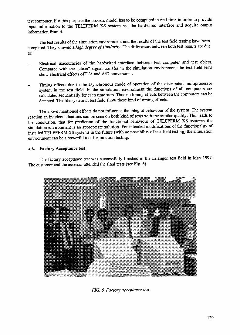
test computer. For this purpose the process model has to be computed in real-time in order to provideinput information to the TELEPERM XS system via the hardwired interface and acquire outputinformation from it.
The test results of the simulation environment and the results of the test field testing have beencompared. They showed a high degree of similarity. The differences between both test results are dueto:
Electrical inaccuracies of the hardwired interface between test computer and test object.Compared with the ,,clean" signal transfer in the simulation environment the test field testsshow electrical effects of D/A and A/D conversion .
Timing effects due to the asynchronous mode of operation of the distributed multiprocessorsystem in the test field. In the simulation environment the functions of all computers arecalculated sequentially for each time step. Thus no timing effects between the computers can bedetected. The life system in test field show these kind of timing effects.
The above mentioned effects do not influence the integral behaviour of the system. The systemreaction an incident situations can be seen on both kind of tests with the similar quality. This leads tothe conclusion, that for prediction of the functional behaviour of TELEPERM XS systems thesimulation environment is an appropriate solution. For intended modifications of the functionality ofinstalled TELEPERM XS systems in the future (with no possibility of test field testing) the simulationenvironment can be a powerful tool for function testing.
4.6. Factory Acceptance test
The factory acceptance test was successfully finished in the Erlangen test field in May 1997.The customer and the assessor attended the final tests (see Fig. 6).
FIG. 6. Factory acceptance test.
129

4.8. Installation and commissioning at site for parallel operation
After the FAT the system was installed on site and commissioned during the outage in July.The TELEPERM XS system network was completely installed and commissioned and selected inputand output signals were provided to the system.
Since July 1997 the system is in operation online open loop in parallel to the old system. Thepurposes of the parallel operation are the following:
- acquisition of operation experience for the pilot installation of a TELEPERM XS system;- division of the commissioning activities on two outage periods;- intensive personnel training on site.
The system is connected to the plant computer information systems via the above mentionedgateways. Thus the operation and failure behaviour is constantly monitored.
For one selected function ,,power distribution control" a second set of control room equipmenthas been installed and the operator has the possibility to choose between the conventional controllerand the new TELEPERM XS system. The TELEPERM XS "power distribution control" is inoperation most of the time with exception of the training and commissioning periods.
The one-year online open loop operation of the TELEPERM XS system serves furthermore foracquisition of operation experience for the system as well as for the failure rates of the components.
REFERENCE
[1] Werner Bastl, Heinz-Wilhelm Bock "German qualification and assessment of digital I&Csystems Important to safety". Reliability Engineering & System Safety 1998 (in print).
130

MODERNIZATION OF I&C IN THE PAKS XA9847296NUCLEAR POWER PLANT
A. HETZMANN, J. EILER, Z. TOTHPaks Nuclear Power Plant,Paks, Hungary
Abstract
The I&C modernization activities are motivated with the next aspects: Demand on new functionalities notincluded in the original design; Reduction of operation and maintenance cost; Increasing of safety requirements;Gradual disappearing of the technical support of the manufacturers; Demand on higher quality of the equipment.Since plant will reach the half of his lifetime within few years, a peak of modernization activities is plannedproviding the stable operation till end of the lifetime. It concerns not only the I&C but other systems as well. Bythe strategy the modernization has to be finished within about ten years. There is a long term and a middle termreconstruction plan for I&C systems. The long term plan defines a systematic approach of modernization. Therealization of the particular projects must not exceed the period of yearly outages. The middle term plan definesthe approved activities and contains allocated resources to them. The modernization activities could be dividedon two groups: a) Reconstruction of existing systems or construction of new ones; b) Systematic 'pin-to-pinreplacement' of certain kind of equipment belonging to different I&C systems leaving the functions and thearchitecture unchanged.
1. SYSTEM LEVEL I&C RECONSTRUCTION AND IMPROVEMENT PROJECTS IN THEPAKS UNITS
The items will be discussed:
- Reactor protection system refurbishment project- Turbine power controller- Core monitoring system reconstruction.- Installation of an on-line water chemistry monitoring system- Steam generator leakage monitoring
Reconstruction of the unit computers
1.1. Reactor protection system (EPS) refurbishment
Due to enhanced safety requirement, the management decided to engage in an overall safetyI&C system upgrade. The project aims at introducing changes and modern solutions into the I&Ctechnology and at restructuring the safety I&C system. These changes affect the actuation algorithmsas reasonable. Introducing changes to the I&C technology means implementing the logic currentlybased on relay circuits by using modern type-tested digital components, whereas system restructuringmeans integrating the existing autonomous safety subsystems into a single three-train system. Therefurbishment utilizing up-to-date tools facilitates the elimination of known algorithm inadequaciesafter performing the corresponding safety analysis.
1.2. Turbine control system replacement
The goal of this project is to establish capabilities of participating in the countrywide primaryfrequency control. It makes possible for Hungary to join the European grid. One unit by year will beequipped with a state of the art turbine controller. The main features are:
- manual control;- automatic control;
RPM control;
131

- power control;combined control;fresh steam pressure control
- limitation functions: power and fresh steam pressure.
1.3. Reconstruction of the core monitoring system
According to the regulations the continuous operation of the units depends on the availabilityof the core monitoring system. Missing the core monitoring functions more then 2 ours, the unitpower must be reduced. Using the latest technology digital equipment for replacement with wellstructured redundancy we could avoid the power losses.
There are other benefits of the reconstruction besides the high reliability. A further softwareimprovement will support the use of newly constructed profiled fuel elements. It will increase the fuelburn out ratio reducing the fuel costs.
The project was started in 1990. A pilot system was first installed running parallel with the oldequipment on unit 1. After a half year of testing period the first installation was carried out in 1992during the annual outage on unit 2. It was followed by the next installations on further units one byyear. During each installation the software was upgraded according to the operational experiences ofthe earlier installed systems.
1.4. Installation of an on-line water chemistry monitoring system
Replacing a former, manually operated sampling system, a new PLC controlled automaticsystem has been installed with the following main purposes:
Reduce the need of the human work;Reduce the personal irradiation dose;
- Provide continuous, on-line sampling in place of the old periodic one.
Due to the rapid evaluation the necessary action could be done faster in case of deviancy fromnormal chemical conditions. The controlled parameters:
In the primary coolant water:- Conductivity;- pH;- Redox potential;
Dissolved hydrogen- Potassium ion;- Ammonium ion.
In the steam generator secondary side:- Conductivity;- pH;- Redox potential;- Chloride ion.
In other parts of the secondary side:- Conductivity;- pH
Dissolved oxygen;- Chloride ion.
132
The samples are directed to the sensors using a manifold valve selector system in the primarycircuit. The total cycle time is 30 minutes. In the turbine hall the circuits have individual sensors. Thetotal number of sampling points is about 100 in each unit. The systems were installed between 1993-96 one per year. The PLC system consists of 9 controllers for the whole power plant. It also includesdisplaying features at any location of the plant via a local area network.
1.5. Steam generator leakage monitoring
The leakage monitoring system indicates the N16 isotope in the fresh steam. Using asophisticated algorithm the leakage can be calculated with high accuracy. The new monitoringreplaces the old fresh steam activity measurement requiring large volume of maintenance work.
The first installation was in 1996. After one year of successful operation the further installationare planned in 1997-98.
1.6. Reconstruction of the unit computers
The technical support and the experts of the old 3rd an 4* generation plant computers aregradually disappearing. Obtaining the spare parts became extremely difficult and is possible mostlyfrom the 'second hand' market.
After a half year of investigation phase a strategic decision was accepted: the new system mustbe constructed utilizing an off-the-shelf software product tailored on the need of the plant. Almostone year was spend on selection of the appropriate software.
The management agreed on a constructing of the pilot system running parallel with the existingof the existing computers without any disturbance of its operation.
The main objectives of the pilot project:
- practical and final confirmation of the applicability of the chosen software product;- to prove the economical expandability without practical limits;
training of the operational and the maintenance personnel;- preparing of the specification and design for final installations.
2. INCREMENTAL I&C UPGRADE IN PAKS
Incremental upgrade means fully or almost pin-to pin upgrade of obsolete equipment. Thereason of the replacement was the demand on higher quality and on reducing he O&M costs. In somecases the need for a new particular function led to the change of the old equipment to a new modemone. The replaced equipment:
- dP transmitter replacement;Pressurizer level measurements;
- Turbogenerator vibration and shaft displacement measurements;- Electromechanical limit value monitors;- penetration replacement;- Recorders.
2.1. dP transmitter replacement
The systematic dP transmitter replacement initiated in 1991 was continued in the last two yearsand now we have more than 350 new transmitters installed in Units 1 and 2. There are four types oftransmitters in use:
133

- Standard type- Standard type with nuclear cleaning- Special design for WWERs.- Smart transmitters
2.2. Pressurizer level measurements
A new computing unit was implemented in the level measuring circuits of the pressurizer, usedfor monitoring purposes in the Main Control Rooms in Units 1, 2 and 3. This computing unitperforms an overall continuous density correction (from start-up to nominal pressure) on the basis ofthe saturated water-steam table. The same device is planned to be installed in Unit 4 this year.
2.3. Turbogenerator vibration and shaft displacement measurements
The vibration and shaft displacement of the turbogenerator sets were refurbished with newequipment. Presently 3 turbines have the new bearing vibration measurements and 5 turbines have thenew shaft displacement measurements.
2.4. Electromechanical limit value monitors
The systematic replacement of the originally implemented electromechanical limit valuemonitors has been continued in the NPP and - at present - almost 600 new, fully electronic limit valuemonitors are installed in the four Units.
2.5. Recorders
A systematic replacement of the obsolete recorders has been launched at the power plant. Todate, 74 recorders have been replaced altogether in the four units. The new devices provide somepractical services like event controlled recording. The project is to be continued in the next years.
134

XA9847297THE STATUS OF I&C DEVELOPMENT INTHE REPUBLIC OF KOREA
I.S. KOO, K.C. KWON, J.W. LEEKorea Atomic Energy Research Institute,Yusong, Taejeon,Republic of Korea
Abstract
It is required to adopt digital technology for the modernization of I&C systems . Outage reports wereevaluated to provide the new design requirements of applying digital technology to NPPs. The overall designrequirements of next generation reactor are introduced, and the replacement plan of Kori unit 1 is described. Inany case of new I&C design, the verification and validation of the function and performance of digital systemshould be done before commissioning. I&C test simulator to validate new developed digital control andprotection algorithms, alarm reduction algorithms, etc. is developed. To evaluate human tasks in control room,the human factors' integration test facility is developed. Some applications with I&C test simulator and somehuman factors experiments are done. These facilities will be able to validate new designed I&C functions andoperator's tasks in the control room.
1. INTRODUCTION
1.1. Problems of operating plants
Existing I&C systems for nuclear power plants designed and built in accordance withtechnologies in the 1960's or 1970's have been faced with problems regarding obsolescence, burdenon maintenance and testing activities, inaccuracy, and unreliability. In addition, it has been difficult toadopt new technologies to improve plant availability.
The outage reports of nuclear power plants have been reviewed to select the upgrade items inthe I&C area. This review was focused on the failure rate in numbers of unplanned trip and in outageduration, the identification of outage causing from a failure of I&C equipment, the source of afa'l lure, the classification of a system failure in accordance with outage and the failure rate inaccordance with operating years.
The percentage of failures caused by I&C was about 17% of duration and 44% of numbers. Atconcern about operating years, duration of failures caused by I&C was 14% the first 2 years, 22% thesecond 2 years, 16% the third 2 years, 23% the forth 2 years and 19% the fifth 2 years.
On the equipment basis, failure rate caused by electronic device was 28% in numbers and 33%in duration, failure rate caused by conductor, power supply, relay and transmitter was 42% in numberand 41% in duration, failure rate caused by control valve was 10% in numbers and 9% in duration andfailure rate caused by electro-hydraulic control was 13% in numbers and 6% in duration. On thesystem basis, instrumentation failure rate was 18% in numbers and 13% in duration, control systemfailure rate was 67% in numbers and 68% in duration, protection system failure rate was 5% innumbers and 6% in duration.
Finally, causes of plant outage were ageing and vibration of components, errors in designing,manufacturing and installing systems and/or equipment and human errors in operating plants andmaintenance of equipment.
1.2. TMI action plan
Current operating nuclear plants were designed by the "bottom up approach". So, training ofoperators is very important to operate the plant, safely and efficiently. When an emergency event is
135

occurred during operation, a huge amount of information will be provided for the operator to takeappropriate action. Understanding of plant status at emergency state, the operator's burden will bevery high. It can lead to an operation error. To provide good design for man-machine interface, "top-down design approach" based on human factors engineering shall be applied.
1.3. Potential licensing issue
Protection of common mode failure of computer system software and hardware is a potentialissue for applications of a digital technology in nuclear power plant. Recently, IEEE approved a newversion of IEEE 7-4.3.2, "Standard Criteria for Digital Computer in Safety Systems of Nuclear PowerGenerating Stations". This criteria will be taken as a requirement for the development of safetyrelated computer system by Korean regulatory bodies. Hence, the development of new digital systemsshall be met with this kind of licensing issue.
It is required that digital technologies is applied to the replacement of the aged analog I&Cequipment in operating Nuclear Power Plants(NPP) and to the I&C systems in new NPP.The application of these technologies to NPP is not fully assure their reliability.
2. DEVELOPMENT OF NEXT GENERATION REACTOR
The basic requirements of I&C system development for the next generation nuclear powerplants in Korea has been reviewed with respect to the conventional I&C systems. The typicalcharacteristics of the advanced I&C systems for next generation are extensive application of thedigital technologies in order to enhance safety and reliability of the integrated I&C systems. Theadvanced I&C systems are also applied to advanced man-machine interface technology to improvehuman factor problems in nuclear power plants.
The I&C system design requirement in EPRI's utility requirements document have beenevaluated. For the development of the Korean I&C design requirements, the various types of designfor I&C systems have been reviewed and incorporated.
The Korean I&C design requirements are:
- Improvement of plant availability and reliability.- Improvement of the maintainability.- Software quality improvement and hardware qualification.- Improvement of the operator support functions.
On the licensing concerns, the common mode failure design criteria and the softwareverification and validation methodology are under discussion.
2.1. Design requirements
NGR plants will be operational after 2005. The trend of I&C technology improvement is veryrapid. Hence, around 2005 the current advanced technology will be getting old. Then Operation andMaintenance(O&M) problems will be occurring. Also, operators of NGR will be very familiar withcomputer operation. Based on these scenario, we selected new concept and/or technology for NGR. Inparallel, we made a decision on resolving potential issues for NGR and current operating plants.
2.1.1. Technical Requirements
- Reliability and availability.Digital technology has many merits, which improve reliability through self diagnosis of failure,stable and drift free operation, and more comprehensive information on plant operating status
136

provided to the operator, while digital I&C systems have some risks for the licensing concernsincluding verification and validation of digital systems, common mode failure, etc.
- Standardization and diversity.For the conventional I&C system design, it is difficult to change design or to replace spareparts due to select components and implemented systems. To reduce costs of O&M, NGR shallhave plant-wide standardization. If standardization is emphasized, the diversity requirementswhich is one of the licensing concerns may not be met.
- Redundancy and segmentation.Since it is expected that new technologies will be applied, including use of computers andmultiplexed data transmission, the requirements need to ensure that the design is as forgivingas possible in terms of the probability and consequences of the failures of this potentiallyshared equipment.
- Maintainability and testability.With the adoption of digital technologies, one of the most significant changes of I&C systemscompared to conventional I&C systems is the remarkable improvement of testing andmaintenance capability including accurate and stable calibration, continuous self-diagnostics,and automatic functional operator/maintenance personnel burden.
- Flexibility and expansion.The technology of I&C equipment is rapidly changing, and obsolescence of equipment is acontinuing concern. Therefore, I&C design must be flexible and expandable to allow for designchanges and replacement of obsolete equipment. In addition, major systems shall be designedwith sufficient performance margin to perform its designed function under condition ofmaximum stress.
- Integrity of software.With the adoption of digital technologies, one of the major concerns related to software is thatsoftware based safety systems may contain subtle failure modes that occurs only under anobscure set of conditions. If standardized software is used to perform similar functions insimilar computer hardware installed throughout the system, then common mode failures coulddegrade overall safety system operation.
- Hardware requirements.I&C system in next generation reactor will be constructed with microprocessor-based systemswhich shares process equipment and data transmission functions. Therefore it is very importantto prevent common mode failures.
- Data communication.The architecture of I&C systems in next generation reactor will be constructed with severallayers for data communication.
2.1.2. Functional Requirements
- Protection and safety system.The important functions of the protection and the safety related systems are to shut down thereactor safely and to mitigate an accident. It is necessary to meet such requirements as theseparation, diversity and independence of these systems.
137
- Control and monitoring systems.These group systems will be provided with monitoring and control capability of the overallprocess of producing energy, transport, and conversion. For reducing operator task error, thesegroup systems provide for automatic operation or unattended operation for continuous or oftenrepeated tasks when the plant is in nominally steady operation above a low power leveloperation. Some reconfiguration actions cannot depend on the operators because of timingconstraints or the risk of error.
- Operation aids and alarm processing function.The functions of these group systems is to provide appropriate information on equipmentstatus, core limits, margins and other plant status for safety operation.
3. REPLACEMENT OF KORI UNIT 1
Kori unit 1 is upgrading Process Protection System(PPS), Process Control System(PCS) andPlant Computer. The upgrade is being driven by growing problems of obsolescence, difficult inobtaining parts, and increased maintenance costs of existing systems. The retrofit of the H-Linesystems (PPS and PCS) and W2500 plant computer at Kori unit 1 will be completed in 1998.
3.1. Design requirements
The safety evaluation under 10 CFR 50.59 which provides the bases for the determination thatthe change, test, or experiment does not involve an unreviewed safety question shall beaddressed, evaluated and resolved.
- The system failure due to software, including common mode failures, and defence in depthshall be addressed, evaluated and resolved.
- The potential effects of electromagnetic interference (EMI) and radio-frequency interference(RFI) on digital-based equipment shall be addressed, evaluated and resolved.
- The potential errors of inadvertent or unauthorized changes to be introduced via man-machineinterface (MMI) for digital-based equipment, and the adequacy of training and proceduresprovided for plant personnel in the use of the new equipment shall be addressed, evaluated andresolved.
- Software verification and validation including commercial grade item (hardware and software)dedication to qualify commercial grade digital equipment for use in safety system shall beaddressed, evaluated and resolved.
4. DEVELOPMENT OF TEST SIMULATOR FOR I&C RESEARCH
4.1. Introduction
Most of the operating nuclear power plants have analog instrumentation and control (I&C)equipment which are increasingly faced with frequent troubles, obsolescence, and high maintenanceexpense. But digital technology provides advantages such as processing of numerous data,improvement of system reliability, flexibility of adding new functions, automation of periodic tests,self- diagnostics, and improved operation and maintenance using standardized components.
Consequently, it is strongly recommended that nuclear industries adopt modern digital andcomputer technology to improve NPPs safety, availability, and operating functions [2]. However, inapplying the digital technology to nuclear power plants, we should ensure that it does not endangerthe safety and reliability of the plant. Verification and validation of the function and performance of
138

the digital system should be done before installation in real NPPs. The purpose of the I&C testsimulator is to verify and validate the newly developed control and protection algorithm, alarmreduction algorithm, and the performance of operator support system using artificial intelligencetechnology. The new developed I&C system should be tested and verified using prototype or mock-upfrom the initial stage of development. I&C system replacements and upgrades usually rely on static orlow-fidelity simulation testing before plant installation, followed by a lengthy startup test to adjustsystem tuning constants. The plant is exposed to huge risk if installation difficulties are encounteredor if the system does not operate as anticipated. The test simulator can be used to test digital I&Csystem upgrades before actual plant installation[3]. The prototype or mock-up receives plant signalsfrom normal and transient states and produces appropriate output signal to verify the plant statetransformed to normal state or operator wanted state. Recently, the digital I&C functions aretransferred to more integrated, intelligent, and diverse. The requested signals to test and verify theabove functions should be continuous and provide real-time characteristics. It is more realistic toreceive these signals directly from operating NPPs, but it is almost impossible. Therefore it isnecessary to develop the I&C test simulator which simulate the behaviour of NPP to test and verifythe developed prototype or mock-up.
The MMIS design process shall include the development of digital computer based dynamicmodels for the overall plant response as well as individual control systems.
The proposed test simulator has drawbacks to test common mode hardware failures andsoftware verification and validation, but it is possible to carry out a dynamic test of the systemfunction which is one step in the process of software verification and validation.
4.2. Functional requirements
4.2.1. Hardware Requirements
The major hardware equipment is computer complex which store and execute dynamicmodeling and supervisory program. The computer complex should provide real-time execution andmulti-tasking function. The computer complex includes hard disk, text and graphic display terminalor X-terminal, and disk back-up system. Among these peripherals, the hard disk should have enoughcapacity to store all generated parameters for a long time in test periods.
The test panel which is assigned a part of operator console in real NPPs is required. In order tocontrol the pumps, valves or status in prototype, the test panel includes push button switch, toggleswitch or function key. The plant status may display in colour CRT or X-terminal to provide highexpandability and flexibility. If necessary, the test panel also includes data display units like LED,lamp, or plasma display. It is convenient to use mosaic tile for easy change or modification of panel.
The hardware input/output (I/O) interface between the host computer and the test panel ordeveloped prototype is also required. The I/O interface should provide fast transfer speed of analog todigital or digital to analog conversion and high conversion accuracy of current and voltage signal.Ethernet communication is also needed interfacing with host computer and developed prototypes.
4.2.2. Software Requirements
The test simulator receives the test input signal from the prototype controller, and providesappropriate output signal to controller after the test simulator mathematical modeling calculates theplant dynamics. The input or output signals should be similar to trend of real NPPs. According to theabove requirements, we suggest software requirements such as real-time mutli-tasking operation,mathematical modeling or scenario of I/O signal, store and retrieval of simulated parameters, I/Ofunction for data transfer to prototype, database management and hardware test etc.
139

In real NPPs, the generated parameter is continuously provided, but in the test simulator, theparameters are updated by some time interval because the system is operated by software. In thiscase, short time interval is more desirable, but it is limited by computer capability and capacity. Indigital I&C, the system also has time interval for the signal is transferred by communication network,test simulator is required to transfer the signal around 200 msec, compared to other digitalapplications.
Another important feature of the system operation is multi-tasking which can accept userrequired supervisory function while the real time module is being executed.
There are two methods to provide proper test signals: the one is plant mathematical modelingwhich is continuously executes any input conditions. The other is a scenario which provides a specificplant signal stored in the computer memory by a uniform time interval.
In case of using mathematical modeling, there are numerous combinations of plant parameters,and it takes too much time to derive several types of initial conditions such as start-up, shut down,critical condition, standby, turbine rolling, 25% load, 50% load, full power etc. The test simulatorshould provide the function of store and retrieval of initial conditions.
The test simulator may provide the function of parameter display to confirm the operationstatus and to utilize during the test simulator development. There are many methods to display theparameters, typically using the graphic tool to display piping and instrument diagram, trend curve, orbar chart. It should be avoided that test simulator provides incorrect test result cause of the trouble oftest simulator hardware itself. Therefore test simulator has to provide hardware test function.
4.3. Development of the test simulator
4.3.1. Overview
The test simulator consists of mainly three parts: hardware facility, software program, and I/Ointerface including graphic user interface. The overall block diagram of the test simulator is shown inFIG. 1. The hardware facility includes HP747i workstation, hardcopy unit, VXI interface module, andsimple test panel. The test simulator provides Ethernet and VME extensions for Instrumentation(VXI) hardware interface to developed prototypes. The VXI interface module will be described inmore detail in the next section. The software mainly consists of process modeling program, interfacemodule, and supervisory program. These programs communicate to each other through sharedmemory. A graphic user interface using the Picasso-3 graphic tool is also provided for efficienttesting usage [4].
4.3.2. Hardware
The major hardware facility is the VXI bus back plane instrument and the simple test panel.VXI provides the interface between the host computer and developed target systems or test panel.
4.3.3. Software
The test simulator software is divided into three major parts: process modeling program whichexecutes mathematical modeling program by real-time, supervisory program that manage userinstructions and interface module that includes variables display in CRT, Ethernet interface, andgraphic user interface. It is useful to handle a lot of data with real-time if the communication betweenprocesses is to be done by shared memory which is the most efficient method of inter processcommunication. Shared common places specified common blocks in shared memory so that otherprocesses can access them.
140

Ethernet
DynamicAlarmSystem
DevelopedPrototype
i :r
1ProcessIWodeHing
Static ProgramDynamic Program
SimulationHost
Computer(HP747i)
interface Module
- VXI Interface• Variable Display- Graphic Interface- Ethernet Interface
SupervisorProgram
- Store DB Data- Get DB Data
from File- Print-out
SelectedVariables
- RUN/FREEZE/ONE-STEP
Interface Host Computer
VXI InterfaceDigital
Input OutputAnalog
Input Output
Hardwire*-———s»
Test PanelIndicator Switch Analog Function
O DN
O... OSW1 SW20
FOXBOROI/A Series
DigitalControlSystem
X-Terminal
DevelopedPrototype
FIG.l. Overall block diagram of test simulator
141

Process modellingThe NPP modeled in test simulator is a 3 loop Westinghouse PWR, 993 MWe, mostly refer toKori Unit 3&4 in Korea. Mathematical modeling code is same as Compact Nuclear Simulator(CNS) which is installed in the Korea Atomic Energy Research Institute (KAERI) NuclearTraining Center.
The nuclear behaviour of the core is calculated considering 25 axial nodes for neutron fluxcalculation and one neutron group. Three delayed neutron groups are used. Decay heat ismodeled with three space independent sources. The rod control system has 4 control banks and4 shutdown banks. The rod control can be automatic or manual.
The primary circuit and steam generators are modeled with two phase capability. On thesecondary side there is the steam system, the condenser, the feedwater system, and the auxiliaryfeedwater system.
Extra water supplies are the residual heat removal system for the primary side and the auxiliaryFW system for the secondary side.
Process modeling programs are consist of static part and dynamic part. Test simulator providesthe function to activate predefined 79 types of malfunctions. This function realizes the transientor accident condition to test the developed target systems. These results of malfunctionactivation show a good performance of the test simulator compared to other transient analysiscodes.
Supervisory Programme
The Supervisory programme comprises all the instruction that should be necessary for runningthe test simulator. This programme provides several types of instruction such as run/freeze,one-step, store, get, change display variable, change value, malfunction, and print out globalvariables.
Interface Module
Interface module can provide software interface to VXI interface and developed prototypeusing shared memory.
Graphic user interface is developed using Picasso-3 graphic tool for whole process diagram.This process diagram displays plant mimics, the status of components and the value of majorparameters. Picasso-3 is a user interface management system supporting object orienteddefinition of graphical user interfaces in a distributed computing environment. Graphic userinterface uses shared memory to acquire the necessary data from the test simulator [3].
4.4. Applications
4.4.1. Automatic Startup Intelligent Control System
The Automatic Startup Intelligent Control System (ASICS) has the supervisor system and thedistributed control system. The supervisor system has the supervisor programme to control thedistributed control system, and the knowledge base which is designed from the general operationprocedures and the operator' s experiences. The supervisor system is implemented using an intelligentreal-time expert system shell G2. The distributed control system has four automation modes such asHeating I mode, Heating II mode, Critical mode and Secondary mode, and each mode has controllersand keep-up bands. The keep-up bands have the check-up function to start each automation mode orthe function to hold on some process variables to allow some operator' s action. The ASICS function
142

is verified receive control input signal from test simulator and send control results to testsimulator[6]. By this way, developed control algorithm is evaluated in real-time environment.
4.4.2. Dynamic Alarm System
The overall objective of Alarm and Diagnosis-Integrated Operator Support System (ADIOS) isto improve the operation performance of the man-machine interface system by integrating alarm,process monitoring, and diagnosis system. The computerized dynamic alarm system for ADIOS isimplemented using G2 real-time expert system shell. The alarms in ADIOS have initially their owndefault priorities which are then changed according to plant-mode dependency, equipment-statusdependency, multi-setpoint relationship, or some other methods. To only verify the functionaleffectiveness of the developed alarm system without investigation of operation performance, the testdata are generated in real-time test simulator by activating malfunctions to make alarm occurringconditions[7]. The generated test data are transferred to target system by the method of sharedmemory.
4.4.3. Accident Identification System
The accident identification system can classify the types of accident or transient in NPPs by itstime dependent patterns related to the principal variables and operating status of major equipment. Inthis accident identification system, the Hidden Markov Model (HMM), a double stochastic processenables modeling of, not only spatial phenomena but also time scale distances, is used for mainidentification method. Self-organizing map which is a kind of neural network is used for vectorquantizer.
The test simulator is used to test the function and performance of the accident identificationsystem by generating simulated accident or transient situations [8]. The configuration of the accidentidentification system and the test simulator and shown in FIG. 2.
TestSimulator Input
patterns
Xt
training
VectorQuantizer
HMMIdentifier Output
L level
Code book
Vectorquantized _
observations Of-A:
identification
HMMparameter
reestimation
training
Normal Model
[Transient Model
Transient Model'
Transient Model Ii
TransientDescription
FIG. 2. Accident diagnosis system with test simulator.
143

4.4.4. Intelligent Logic Tracing System
The Intelligent Logic Tracing System (ILTS) shows the logical paths between an interestedstate graphically together with the description of causes as results of diagnosis in a displayed logicdiagram. And the state of a logic element like gate in diagram is displayed and updated in real timewith a colour, e.g. red for on-state and blue for off-state. ILTS is tested with real-time test simulator[9]. FIG. 3 shows the block diagram of ILTS connected with test simulator.
TestSimulator
ILTSKnowledge"Generator/
PlantLogic Diagram
Input
lLogic Diagram
Knowledge Base
LoggedState DB
GraphicDB
CurrentState DB
LogicDiagramDisplay
Node StateDiagnosis
FIG. 3. Intelligent logic tracing system with test simulator.
5. HUMAN FACTORS RESEARCH
5.1. Introduction
Interests in human factors in nuclear power plants have been grown in the early 1980s after theTMI accident. Bring influenced by this international trend, Korea Atomic Research Instituteorganized human factors team in 1988. Long term projects for the development of nucleartechnologies starred in 1992 in KAERI. The Development of Human Factors Technology project isone of the projects. This project was planned for five years in two sub-project; the Development ofHuman Factors Experimental Evaluation Techniques and Development of Human BehaviourAnalysis Techniques. The former has two objectives; one is to establish human factors experimentfacility named Integrated Test Facility (ITF), and another is to accomplish the techniques for humanfactors experiments. The later sub-project has two research areas. One is the development of SACOM(Simulation Analyser with a Cognitive Operator Modal) for the assessment task performance by usingthe simulation of control room operation. Another area is the analysis of human error cases occurredin Korean nuclear power plants and the development of application systems, such as INSTEC(Information System of Trip Event Cases) and MARSTEC (Multimedia Authoring and representationSystem of Trip Event Cases).
144

5.2. Development of itf and experimental techniques
The details of ITF have been designed from 1995,[10] and the test of ITF was completed inMarch of 1997. ITF consists of KAERI-HMS (Human-machine Simulator) and experimentalmeasurement systems. The KAERI-HMS includes a full-scope PWR type nuclear power plantsimulator with many VDU-based workstations. ITF has three rooms; main test room (MTR),supporting test room (STR), and experimenter control room (ECR). FIG. 4 shows the configuration ofITF. In the MTR, there are an operator station with many visual display terminals and alarm panels, ashift supervisor station, a large scale display panel (LSDP), and experimental measurementequipment. For experimental measurements, a telemetry system for physiological signalmeasurements, an eye tracking system, and a three dimensional motion analysis system for measuringoperators' hand movements are located in the MTR.
Main TestRoom
Annunciators
LSDP
Operator Station Microphone
SupportingTest Room
4CCTV Camera
Supervisor Station Eye TrackingSystem
CCTV CamerasTelemetry
System
Viewing Window
Experimenter Control RoomEngineer Station Instructor Station DAEXESS Station
FIG. 4. ITF configuration
145

There are three CCTV cameras to record operation scene, and three microphones, two at theoperator station and one at the shift supervisor station, to provide and record communication amongoperators and a shift supervisor in the MTR and experimenters in the ECR.
The DAEXESS workstation which is in the ECR is a system for experimental data analysis. Asshown in FIG. 5, operators in the MTR interact with the plant simulator through the interfaces whichare manipulated with HMI software. Operator action log, alarm event log, and plant parameter historyare produced respectively by the HMI software, simulation model, and instructor software of the hostcomputer. Then, SCADA (Supervisory Control And Data Acquisition) software in the host computercollects and stores the data. The SCADA synchronizes the time of data from the telemetry system, theeye Tracking system, and the three-dimensional motion analysis system to the time of host computer,and processes the data formats to be suitable for the DAEXESS. The DAEXESS receives all the datafrom SCADA and integrates with audio and video records from the audio and Video control system.With the data shown on the DAEXESS station, experimenters can perform various analyses, such asdebriefing analysis, statistical analysis, operator performance analysis, etc. In this display, from thetop, there are a menu bar, a time frame display bar, bars with marks for system event data and verbalprotocol data, a telemetry data window, and two video display and control windows that are selectiveamong the audio and video control system, the eye tracking system, and the three-dimensional motionanalysis system.
Along with the development of ITF, the development of experimental techniques has been triedin part by performing pilot experiments, such as an experiment for suitable information density on alarge display and one for the evaluation of HMI design of a compact nuclear simulator. In the processof the pilot experiments performed, a scheme of experiment planning and software for processing andrepresenting the data from the telemetry system and eye tracking system were developed [11, 12].
Host Computer DAXESSWorkstation
TelemetryData
TelemetrySystem
EyeTracking
Eye TrackingSystem
A/VData
A/VRecording
System
FIG. 5. Experimental dataflow.
146

5.3. Development of SACOM
We intended to develop an operator task simulation tool for dynamic assessment of operationperformance in the main control room of NPPs. To investigate the characteristic frames of operatortasks, we analysed operators performance at a full-scope training simulator running severalemergency operation scenarios. We investigated the requirements of tasks that operators shouldperform in accordance with the scenarios before the simulator operation. Then, operator performanceon the simulator was reviewed compared with the requirement frames of the tasks. The review wasperformed with the operators participated in the simulator operations and other operation experts.Based on the results of this investigation and cognitive mechanisms from literature, the conceptualframe of SACOM was made. For the development of SACOM, we focused on human factorsevaluation of HMI designs in both conventional and VDU-based types. With the SACOM, we canestimate physical workload, cognitive workload, and information requirements as primary measures,then assess the arrangement and layout of control panels and devices, the quality of informationstructure compared to task requirement, the suitability of function location and procedures, and errorpotential, when comparing design alternatives or finding human factors problems in a design [13].We developed a new cognitive task analysis method for derivation of task requirements andassessments of cognitive workload based on the concepts of cognitive span, working memory reliefpoint, and work memory load [14, 15]. As shown in FIG. 6, SACOM has three major modules; anoperator model, an interaction analyser, and a situation generator. A prototype SACOM wasimplemented for an emergency operation scenario on a blackboard architecture.
5.4. Analysis of human error cases and development of applications
Human error is an important factor for the operational safety and effectiveness of nuclearpower plants. It is effective against human errors to analyse human error cases and present theinformation obtained from the analyses to plant personnel. In Korea, Nuclear Power Plant Trip CaseReports are issued annually and describe the component failures or erroneous tasks involved in thetrip cases, the progress of events, remedial actions and investigations after the trip, andrecommendations to prevent similar incidents. The reports printed in documents, however, are noteffective in the use of reports. The reports identify human errors in a very limited sense, e.g. only forthe wrong operations.
Operator Model Interaction Analyzer Situation Generator
Domain KBSystem
Function K.System
Structure K_
Procedure K_Huristic K.
BB
•
SymptomsHypotheses
PactsGoals
InternalSituation
Table
Run MonitorExecution/Action Profiler
Workload ProfilerPlant Situation Monitor
Visualization ModuleAnimation Processor
Path GeneratorGraph Generator
Output AssessorWorkload Assessor
Interface Design EvaluatorError Potential Checker
Sensitivity AnalyzerStatistical Assessor
Situation TableSituation Table
Manager
Scenario Controller
Design Profiler•HMI• Job Allocation•Aids• Fault, etc.
Interface
ri6rtertt^SlmuStor_"j
FIG. 6. The structure of SACOM.
147

Hence, it will be necessary to carefully analyse again the reports in order to find out somethingon erroneous actions. The sequence of events in the reports is described too briefly in many cases,while the supportive information, such as the actions taken to find the causes and the principles ofequipment operation, is well described. This may cause readers to confuse in understanding thesequence of events. The information helpful for understanding the progression of incidents issometimes described only in the causes of incident, the problems of incident, or the remedies toprevent similar incidents. Since the reports are available only in document form and the cases areclassified only by major systems, the reports are not effective for the activities such as the search ofsome specific cases and the investigation of analogy and Wends existing among the cases. In order toresolve these problems, it was decided to analyse and arrange again the information of case reports. Aretrospective analysis procedure and an error classification system were initially developed for theanalyses of human error cases in Korean nuclear power plants . These have been revised in theprocess of case analysis [16]. A total of 79 cases was identified from 276 trip cases occurred from1978 to 1994. A summary of analysis was made for every trip case, and detailed descriptions of eventsequence were made additionally for the cases that human errors were involved. In the summary ofanalysis, the critical events are described more clearly than in the reports, and the problems andremedial actions are described consistently with the critical events. The detailed descriptions of eventsequence represent the sequence of unit events in a time-lined table form.
Since the reports describe the cases mainly with equipment or component malfunctions, muchportion of the information was changed for the cases involving erroneous actions.
We developed INSTEC and MARSTEC for the applications of information obtained from ourcase analyses. The INSTEC is a database system for the search and retrieval of the information. TheMARSTEC is a multimedia-based instruction system on specific human error cases.
As shown in FIG. 6, the authoring interface of MARSTEC provides tools for input andprocessing of information differently to the types of information.
At present, MARSTEC was implemented with a few cases. The MARSTEC was demonstratedto instructors of a nuclear training centre. The response showed that MARSTEC would be a usefultool for the instruction of information on the trip events.
t
1Static
1
Authoring Interface
Information
Semi-dynamic
\
Dynamic
1Representation Interface
\ 1
rIndex I
Trace 1Hie 1
h-search of
\^^J y-°~-y v yFIG. 7. Information processing with MARSTEC.
148

REFERENCES
[ 1 ] S. Koo, "Draft Design Requirements of I&C for KNGR", IAEA Technical Committee Meetingon Advanced C&I Systems in NPPs, Espoo, Finland, June 20-23, 1994.
[2] C. Kwon, et al., "Proposed Plan for the Development of Advanced I&C Technology in Korea"IAEA Technical Committee Meeting on Advanced C&I Systems in NPPs, Espoo, Finland, June20-23,1994.
[3] Mikell Lord, "Simulator testing of digital control systems," Nuclear News, Sep. 1994, pp.35-38.
[4] OECD HRP, The Picasso-3 User Interface Management System User's Guide, Sep. 1996.[5] C. Kwon, et al., KAERI Training Simulator process Description, July, 1988.[6] H. Jung, et al., "Development of Automatic Startup Intelligent Control System for PWR plant,"
Cognitive Systems Engineering in Process Control, Kyoto, Japan, Nov. 12-15, 1996, pp. 51-56.[7] Y. Lee, et al., "An Implementation of Alarm and Diagnosis-Integrated Operator Support
System," Cognitive Systems Engineering in Process Control, Kyoto, Japan, Nov. 12-15, 1996,pp. 63-70.
[8] C. Kwon, "A Stochastic Approach with Hidden Markov Model for Accident Diagnosis inNuclear Power Plants," submitted to IEA/AIE'97, Atlanta, Georgia, USA, June 10-13, 1997.
[9] P. Lyu, "A Study of Logic Display to Monitor the States of Logic Elements," NPIC&HMIT96,The Penn. State Univ., USA, May 6-9, 1996, pp.429-436.
[10] Sim, et al., "The Development of Functional Requirements for Integrated Test Facility,"Proceedings of the IAEA Specialists Meeting on Advanced Information Methods and ArtificialIntelligence in Nuclear Power Plant Control Rooms, IAEA-12-SP384.37, Halden, Norway, Sep.13, 1994.
[11] C. Lee, et al., "Human Factor Experiment Design in Using the Integrated Test Facility,"Proceedings of the 3rd Pan-Pacific Conference on Occupational Ergonomics, Seoul, Korea,Nov. 13-17, 1994, pp. 424-428.
[12] H. Lee, et al., "Application of Reactor Operator's Behavioural and Mental Workload Databasefor Evaluation of Nuclear Reactor Control Systems," Proceedings of Cognitive SystemsEngineering in Process Control(CSEPC 96), Kyoto, Japan, Nov. 12-15,1996, pp. 159-165.
[13] H. Lee, et al., "Development of an Operator's Cognitive Task Simulation Analyzer ofOperators in Nuclear Power Plants using Blackboard Techniques," ANS Topical Meeting onComputer-Based Human Support Systems: Technology, Methods and Future, Philadelphia,Jun.25-29, 1995.
[14] H. Lee, et al., "A Multi-Layered Method Cognitive Task Analysis in Nuclear Power Plants,"Proceedings of 1st International Conference on Applied Ergonomics(ICAE'96), Istanbul,Turkey, May 21-24,1996.
[15] H. Lee, et al., "A Cognitive Task Analysis Method for Procedure-Based Tasks in NuclearPower Plant," Proceedings of Cognitive System Engineering in Process Control(CSEPC' 96),Kyoto, Japan, Nov. 12-15,1996, pp. 261-267.
[16] O. Park, et al., "A Study on Erroneous Actions Occurred under Rotating Shift System ofKorean NPPs," Halden Reactor Project Workshop on Studies of Operator Performance duringNight Shifts, OECD Halden Reactor Project, HWR-462, Apr. 1996.
NEXT PAGE(S)left BLANK
149

MAIN TRENDS IN MODERNIZATION OF I&C XA9847298SYSTEMS AT NPPs IN THE RUSSIAN FEDERATION
A.B. POBEDONOSTSEVOKB Mechanical engineering,Nizhny Novgorod
A.G. CHUDINRussian Federation Ministry for Atomic Energy,Moscow
Russian Federation
Abstract
There are more than 20 nuclear power reactors in operation in Russia, which have been operated over 10years [5, 6]. Operational time of I&C systems of those NPPs is about 30 years, though the lifetime of individualparts of I&C systems is limited by 10-15 years. I&C systems were designed in 60-70-th in accordance with theexisting regulations and available technical solutions. Obsolesce of those I&C systems require the reconstructionof existing systems. There are considerations that don't allow to perform equipment replacement one-to-one butrequire to modernize I&C systems at NPP.
1. INTRODUCTION
There are more than 20 nuclear power reactors in operation in Russia, which have beenoperated over 10 years [5, 6]. Operational time of I&C systems of those NPPs is about 30 years,though the lifetime of individual parts of I&C systems is limited by 10-15 years.
I&C systems were designed in 60-70-th in accordance with the existing regulations andavailable technical solutions. Obsolesce of those I&C systems require the reconstruction of existingsystems. There are considerations that don't allow to perform equipment replacement one-to-one butrequire to modernize I&C systems at NPP.
2. REASONS FOR I&C SYSTEMS MODERNIZATION
There are some reasons for I&C modernization at NPP. One of them is the equipmentobsolesce. In most cases it is not possible to perform equipment replacement to a similar one. Thereasons are as follows:
- evolutionary changes took place in the field of I&C systems. Analogue equipment have beingreplaced by digital equipment based of computer technology;
- in many cases the existing operational I&C equipment has not been produced any more.
The next reason to make modernization of I&C systems are the changes in regulations, whichnow include more stringent requirements related to quality, safety and reliability. Codes OPB-88 andPBY RU AS-89 contain the new requirements for NPP I&C systems such as:
requirement for diagnostics applied not only to technological equipment but also to I&C shardware and software;
requirement for information support of the operator;
requirement for independence and redundancy of protection system channels, etc.
151

3. GENERAL APPROACH TO MODERNIZATION
The I&C systems modernization at NPP is the complex task. Complex approach to I&Csystems modernization regarding a new NPP takes into account an ability for I&C systemsmodernization in the future. I&C systems design should meet the following main requirements thatallow for I&C systems modernization in the future:
I&C structure should be decentralized and open; I&C systems hardware should utilise moderntechnology and have a module design;
standard (including international) interfaces should be applied to connect different componentsof I&C systems;
- I&C systems hardware should be designed such that sufficient reserves will be available toincrease in future the number of input/output signals without making changes in the hardware.
Complex approach to modernization of an operated NPP requires the development of alongtime schedule of I&C systems modernization for each NPP power unit. That schedule shouldprovide step by step modernization strategy.
Modernization should be related not only to hardware but to functional part of I&C systems aswell. For example, during the modernization of the reactor control and protection system (CPS) it isnecessary to analyse compliance of CPS design to new regulation requirements (single failure criteria,common cause failures). It could require the addition of protection signals, changes in measurementchannel schemes, etc.
In the cause of modernization process it is necessary to take into account the human factors. Atthe earliest stage of requirements specification for system modernization, an appropriate NPPpersonnel should take part in the development of them and finally to agree on the developed set ofrequirements. Sometimes the modernization includes changes in the operator interface, in this casethe operator interface changes should be discussed with NPP operators.
NPP operators training in modernized human-machine interface should precede theimplementation of modernized interface in NPP.
4. CURRENT PRACTICE OF RUNNING THE NPP MODERNIZATION PROJECT
Modernization of I&C systems at operating NPP is under way in Russia now. Modernizationusually consist of individual system hardware replacement or implementation in addition to existingI&C systems new additional systems. Such activity is not intended for large-scale modernization.Great efforts are undertaken in the field of operator support system (OSS) development andimplementation. The working group composed by the specialists of several organizations developedthe concept of information support system for operation personnel of operating NPP on the request ofConcern Rosenergoatom.
The main objective of an information support system is to help an operator in the main controlroom to evaluate a safety status of power unit. The first priority functions of operator support thatintended for the implementation at the operating NNPs are a critical safety functions display,intellectual annunciation system, early fault detection and diagnosis. Information support system ofoperator can be implemented as a separate computer module integrated in operating process controlsystem of a power unit. The work of the implementation of an information support system is beingcarried out in the framework of modernization of operating process control system. It is supposed tointroduce OSS at operating NPP through several stages, in a step-by-step way. The implementation of
152
OSS should be performed on the basis of the analysis at every power unit of available information,personnel activity and definition of a set of the OSS functions to be developed [1].
The development of OSS is carried out by several Russian organizations. Such work isperformed not only in the scope of I&C modernization but for new NPPs as well. For example, theOSS design for Voronezh nuclear heating plant has been developed by OKB Mechanical Engineering.
One of the directions in the field of OSS is the development of Safety Parameters DisplaySystems (SPDS). The pilot programme for SPDS design and implementation at Balakovo NPP(PWR) and Leningrad NPP (RBMK) are developed in Russia. The Russian organizations andAmerican firm Westinghouse took part in SPDS development in the framework of this programme.Westinghouse has successful experience in the area of development and implementation of SPDSsystems in USA [2].
Activity for diagnostic system development and implementation for NPP technologicalequipment and processes diagnosis are being also performed in Russia. Examples are: vibrationmonitoring, equipment lifetime assessment, leakage monitoring, loose parts monitoring. Thosesystems are implemented as local autonomous information systems. Data about the status of thetechnological process is received by diagnostic system from existing information systems. Thediagnostics systems begin to be implemented at NPP. At the beginning of 1993 the expert on-linediagnosis system was put into trial operation at Leningrad - 1 NPP. At present this system is used todiagnose 11 technological subsystems. The diagnosis system provide the following functions:
monitoring the technological subsystems at the macro-level (healthy-unhealthy);
- identification the type of malfunction, its cause and location;
- presentation on the display screen numeric and trend data on any subsystem being diagnosed;
recording the diagnosis result and storing in the archive on the user request.
Moscow Science and Research Center SNHP developed new modem hardware complex forWWER-440 reactor control and protection system (AKNP-7, AZTP, ALOS, AOP and AKNP-7-02for WWER-1000). It meets modem normative requirements. It provides for neutron flux monitoring,data and protection signal processing, representation and recording of information. This modemcontrol and protection system was installed at South-Ukraine NPP and Rovno NPP in the Ukraine aswell as at Kola NPP-1.2 and Novovoronezh NPP in Russia. Reactor control & protection system(CPS) modernization has been performed for the unit 3 of Beloyarsk NPP (fast breeder reactor) byNPO, "Avtomatika" (Omsk, Russia).
Russian organizations take part in CPS systems' modernization for Ukraine NPPs as well. It isintended that for South-Ukraine NPP several CPS subsystem (ROM, ARM, control of control roddrives) be realized on the base of microprocessors. Operation will be possible after the completion ofsoftware and hardware licensing [7]. It is necessary to note that the quality of production technologyof reactor control & protection systems in Russia does not always correspond to the level of thesystem design. This is the main reason why foreign firms co-operate in a number of CPS designsprojects. The successful experience of Russian and French firms collaboration has been alreadyexperienced while developing the functional part of CPS for Kola NPP-3 and 4 [4].
Collaboration of Russian organizations with foreign firms has some specific features. Design ofI&C systems in the scope of modernization always is done by Russian organizations. Russian designorganizations define the modernization strategy, key technical solutions, perform safety provisionsubstantiation and are responsible for correctness of a design. Such approach is conditioned by largeexperience and knowledge in the field of NPP technological processes, Russian standards and
153
regulations related to I&C systems for NPPs, current practice of I&C systems development andoperation in Russia. Collaboration of Russian organizations with foreign firms includes adevelopment of methodology for individual tasks solving (for example, SPDS). Russian organizationsperform in this case the analysis of methods for problem solving and their adaptation for Russianconditions. Sometimes foreign hardware for I&C systems modernization is utilized. In this case it isexpedient to involve foreign firms that have the experience in such technology application in themodernization project. Collaboration provides for optimal technical solutions and helps to eliminatedesign errors related to foreign hardware utilization.
5. CONCLUSION
It is intended to modernize I&C systems on NPP on a basis of a complex approach. The long-time schedule of I&C systems modernization for each NPP power unit should be developed.Such schedule should provide for a stage-by-stage modernization strategy.
Modernization should be related not only to hardware but to functional part of I&C system aswell.
Current practice of information system modernization usually consist in adding to existing I&Csystems new systems (OSS, SPDS, diagnostic systems) that are realized as local systemsconnected with existing I&C systems for process information acquisition . It is supposed tointroduce new systems into operation gradually and increase their functionality step-by-step.
- Control system modernization is performed in the first turn for safety important systemsincluding reactor control and protection systems.
Design for I&C systems modernization for Russian NPPs must be done by Russianorganizations that are specialized in the field of I&C systems for NPPs development. The mainreason is that Russian design organizations have large experience and knowledge in the field ofNPP technological processes, Russian standards and regulations related to I&C systems forNPPs, current practice of I&C systems development and operation in Russia. When it isexpedient from economical and technical point of view foreign firms together with Russianorganizations take part in the works on I&C systems modernization.
REFERENCES
[1] V.G.Dounaev, V.V.Golovanov. The concept of an information support system for operationalpersonnel of operating nuclear power plants. Operator support systems in nuclear power plants.IAEA, Vienna, 1994, IAEA-TECDOC-762.
[2] J.Boucau, S.Smirnov, A.I.Gorelov and all. The SPDS as a tool to improve post-accident strategyon W E R and RBMK reactors. Operator support systems in nuclear power plants. IAEA, Vienna,1994, IAEA-TECDOC-762.
[3] E.O.Adamov, O.N.Glazov, A.P.Eperin, N.V.Strepetov. The design concept of an on-linediagnosis system of a sophisticated technological object: the shell of expert diagnosis system"Dasha". Operator support systems in nuclear power plants. IAEA, Vienna, 1994, IAEA-TECDOC-762.
[4] G.I.Biryukov, N.P.Konoplev, I.V.Pogorelov. Reconstraction of control and protection systems ofWER-type reactors in Russia. Instrumentation and control of WWER type nuclear power plants.Proceedings of the IAEA meeting, Prague, Czech Republic, 27-29 September 1994, NuclearResearch Institute REZplc, 1995.
[5] Nuclear Power Reactors in the World. Reference Data Series '2. IAEA, Vienna, 1992.
154

[6] Instrumentation and control of WWER type nuclear power plants. Proceedings of the IAEAmeeting, Prague, Czech Republic, 27-29 September 1994, Nuclear Research InstituteREZplc,1995.
[7] D.A.Anufriev, A.M.Afrov, N.P.Konoplev, I.V.Pogorelov. Main trends of WER-type RP control,monitoring and protection systems modernization. OKB "Gidropress", 1996.
NEXT PAGE(S)'•ft BLANK
155

MODERNIZATION OF I&C: A STEPWISE XA9847299LEARNING PROCESS WITH A FINAL VISION
P. VAN GEMSTABB Atom,Vaesteraas, Sweden
Abstract
In spite of some political signals it is expected that the life time of nuclear power plants in the Nordiccountries will be as designed for. As the economical life time of the I&C equipment is less than thecorresponding life time of the plant a strategy for modernization of it must be developed. To modernizeequipment during ongoing operation of the plant is not only a technical challenge but also a challenge to humanrelations. It will give a unique chance for the old generation, who built the plants, and the young generation, whohave to modernize the plants, to discuss common problems and new ideas. The purpose of this paper is tosummarize some important aspects which can be included in the content of the planned IAEA book.Furthermore some examples of modernization project in Sweden are given.
1. BACKGROUND
1.1. Lifetime phases
During the first lifetime phase of the power plant the I&C equipment is repaired and modifiedon an "event" controlled way. What I am meaning with the word "event" is that repairs andmodifications are decided and carried out when component faults or design errors are detected. Theseactivities are carried out on a short term basis.
As the equipment became older such short term activities will increase until a moment thatsome drastically and other methods have to be decided. Such decision must be taken before the costsfor repairing become so high that it is difficult to "free" capital for investments in new equipment.This is the situation for many nuclear power plants in the Nordic countries.
In order to guarantee the safe, reliable and economical operation of the power plant strategiesfor modernization of I&C equipment are developed, initiated and carried out. Such strategies willoften cover a long time period of several, up to, 10 years.
1.2. Strategy
Depending on the age of the plants and the type of technology of the I&C equipment differenttypes of strategies are developed. A common element for all strategies is that modernization shall beprepared during plant operation and be carried during the normal planned refueling outages. The maingoal is that modernization shall not reduce the plant availability. The plans include a learning processwith a stepwise replacement of equipment.
The most important decision from the start is that all modernization shall be a logical part ofthe final I&C integrated configuration after the modernization process during many years. How thisfinal "vision" can be reached has been the subject for different studies.
It is obvious that two different strategies are possible. The first one is to replace systems one byone and provide possibilities to connect these later into a final integrated I&C system. The advantageis, of course, that systems and the later network can be purchased with the latest technology in freecompetition. The disadvantage is that much software engineering is required to integrate the systemswith the network. Solutions for such integration are often unique and not supported as a standarddesign.
157

Another strategy is to establish the infrastructure "network" for the I&C from the beginningand to connect systems stepwise later. The advantage is that integration costs are reduced because thestructure is a well proven standard design. The disadvantage is of course that often standard systemsmust be purchased from the same manufacturer as for the network. The choice of technology is notlonger totally free. This option seems to be the most economical one today.
Common for both strategies is that the first modernization step must be selected with regard to:
- the best spin-off for learning of the use, maintenance and the operation of new technology
- the volume of communication to other systems in order to define the requirements for but alsoinstallation of the infrastructure
A typical example for this first step is the plant process computer with control room MMI andcommunication to other computers and to the process I&C.
As a minimum following aspects shall be included in the strategy:
- the final I&C structure "vision"- the method for integration- selection of the first step- limitation and restrictions
safety and licensing- functional upgrading- step by step implementation- new technology- products- design requirements- project organization- Budgeting
2. MODERNIZATION ASPECTS
2.1. Vision
It is clear that the modernized equipment shall be based on digital technology. The differentsystems shall be connected with each other by networks.
Different types of networks shall be available as for:
- process control and supervision- control room MMI- plant technical and administration servers and computers
2.2. Limitation and restrictions
Modernization of I&C for an existing plant must take care of some limitations. Such limitationsmust be defined as a policy in the beginning of the modernization process.
The limitations can be a result of:
the plant layoutintegration philosophy of the I&C
158

- available free spaces- existing process systems- existing control room and maintenance organization and staffing- available time during refueling outages- money
2.3. Safety and licensing
The main safety goal is to increase safety by using more modern safety requirements.Requirements can be obtained by reading formal criteria and standards or by executing a PSA(Probabilistic Safety Assessment).
However, as the plant was designed for many years ago, it can be problem to meet all modernrequirements.
The limitations and restrictions as mentioned before can put limits on the modernization of thesafety. Deviations between the modernization goals and formal modem requirements must be listed,evaluated and agreed upon with the licensing authorities. For some old power plants in Sweden suchdeviations against formal requirements are evaluated with a PSA (Probabilistic Safety Assessment).The PSA methods can also successfully be used to identify weak points in the existing design.Another input for increasing safety are the evaluation reports for transients, incidents or accidents.
An important discussion point in the Nordic countries is what type of safety standards shall beused. IEEE, which was used for the original design, or the newer as IEC. Very often IEEE is selectedas the other mechanical and process systems are also following USA criteria and standards.
2.4. Functional upgrading
The main reason for modernization is to replace an obsolete equipment. To improve functionsis often not foreseen but can be identified later.
Typical new functions are:
- increasing the degree of automation- improving the operational support
improving the administration of maintenance- reducing manpower- specialist engineering support- better process transient management
A normal input for the decision for upgrading functions is to study operational reports or tointerview operation and maintenance personnel. Interviewing personnel is also a good method toengage the plant personnel as early as possible in a modernization process.
2.5. Step by step implementation
As mentioned before a step by step modernization is required for different reasons. For most ofthe plants to start with a few stand-alone steps is preferable to gain experiences for modernization andto increase the competence of the staff. In order to guarantee the learning aspects formal agreementscan be signed between the original builder of the plants and the utilities.
Another point is of course that the size of the individual modernization has to be limited inorder to make it possible to install them during a normal refueling outage. An important aspect is toprovide space for new equipment by step by step removal of old equipment.
159

Modernization can be carried out for components, systems or integrated I&C systems. Animportant goal is to let all modifications be a part of the final, long term, I&C configuration.
In order to make the step by step approach possible the new equipment must communicate withthe existing equipment. This must be planned very carefully. Consequences for the personnel tooperate and maintain two type of technologies at the same time must be clarified.
2.6. New technology
New technology can solve current problems in a better way and in this way increase the safetyand improve the plant availability. It can further include the best of the existing equipment. The newequipment has also possibilities to include new or improve old functions.
However, a new equipment has new characteristics different from the existing equipment. Suchnew characteristics have to be identified and the influences on safety and operation must beevaluated.
Typical new characteristics for digital equipment are:
Functions are carried sequentially and the computer load varies depending on the plantsituation. There is a risk for overloads during big transients in the plant if the software systemis not designed properly.
- Software can be complex and risk for common design errors are increased. This can increasethe volume of CMF (Common Mode Failures) if counter measures are not planned orimplemented properly.
- Due to the sequential way of working the time response for the new equipment differs from theexisting analogue or relay equipment
Concentration of many functions in fewer hardware units makes it difficult to analyseconsequences of hardware faults. Such faults can influence the operation of more processsystems than before.
- Modern equipment includes methods and tools which are not suitable for nuclear safetysystems. Examples are downloading of data and programs and open communication. Security("sabotage") can be a problem if such new methods are allowed in safety systems.
- Elder plants are not provided with sufficient grounding or other measures for reducingelectrical and magnetic interference. Before installation of modern equipment this problem hasto be studied and suitable counteractions to be taken. Due to European laws standard equipmentpurchased within Europe has been tested for EMC thoroughly.
2.7. Products
As mentioned before the strategy must include a vision of the final and long term I&Cconfiguration. This is only possible by using off the shelf products with standardized hardware andsoftware communication modules. The manufacturer of the products must guarantee a long termsupport. Special products only for nuclear application cannot be supported in a long term. Usingstandard products with operating experience will also reduce development costs and delivery timesand increase availability of systems.
The nuclear application will therefor be designed with standard hardware and software modulesfrom an industrial standard product family. Typical nuclear requirements will be designed into the
160

target system by using the standard modules in specified way. Above mentioned reason is thebackground for the decision of some utilities in the Nordic countries to base the long termmodernization on products of the same manufacturer.
2.8. Design requirements
Design requirements must be specified early in the modernization project. They must be underQA control. They must include following aspects:
Reconstruction of the original requirements;
Adaptation to new technology;
- Adaptation to newer safety requirements;
Increasing of operational and maintenance functions or support;
- Methods for coexistence of new and old equipment;
Use of modern methods as for:
- Human factor engineering;- Verification and validation;
PSA (Probabilistic Safety Analysis);- Full scale simulation training and validation;- Design tools for programming and CAD systems;
FMEA (Failure Mode and Affect analysis);
- Reliability analysis;
- Environmental characteristics, separation, earthquake and other typical nuclear requirements.
Requirements are divided into general requirements valid for the whole I&C and requirementsfor standalone systems.
General requirements will often result in the design of configurations "infrastructures" for:
- whole I&C system- the control room complex- auxiliary electrical power system.
A point that has already being identified in current projects is that new equipment and newsafety rules need other types of power supplies and will require changes in the electrical power supplysystem.
2.9. Project organization and budgeting
Modernizing I&C during continuous operation is not easy. It need a well structured project andproject organization. Strategies have to be decided and plans to made up for a stepwise introductionof new systems. Different types of experts from different organizations have to be contracted. Theproject must be authorized by and accepted in the whole organization of the utility. Especially the endusers within the operation and maintenance departments must be engaged from the beginning.
161

Informal information meetings with regulatory authorities have to be organized and formallicensing process must be planned and carried out. Personnel has to be trained on new equipment.
In order to install and commission the new equipment during a short refueling outage it isnecessary to prepare for installation already during the operation of the plant. This must be donewithout jeopardizing safety or plant availability.
All these aspects together make it sometimes more difficult to modernize an existing plant thanto build a new one. By means of informal quotations price levels for equipment has to be estimatedand a long term budget must be worked out. This budget is approved by the management of the plant.
3. EXAMPLES
3.1. Ringhals 1 NPP
The Ringhals 1 is a BWR owned by the State Power Board in Sweden. It is located at the westcoast of Sweden. The plant I&C and electrical systems were designed around 1970. As common inNPPs in Sweden well proven standard components were used during the design with a documentedoperating experiences during several years. That means that already at the start of the plant thesystems did not represent the current state of the art. After many years of operation it is obvious thatthe availability of spare parts is a problem today and can be worse in the future.
For this reason a modernization of all I&C and electrical systems was decided in 1995 .The goalof this modernization was to replace systems during 6 annual shutdown periods starting in 1997.
The modernization started with an engineering phase in cooperation with the designer of theplant ABB Atom. The goal for this engineering phase was to define different type of criteria andtechnical specifications. The engineering was carried out as a typical top down project during 1995-1996. The result of this phase shall be used as the input for detailed specification of the modernizationduring the annual shutdown periods. The first modernization step is the replacement in 1997 of theI&C for the plant waste handling. The organization of the engineering is shown in Fig. 1.
The engineering phase
FIG. 1. The Ringhals 1 modernization project.
162

3.2. Forsmark 1 and 2 NPP
The Forsmark 1 and 2 are BWRs at the coast of the Baltic sea in Sweden. The first one wasstarted in 1980 and the second one a year later. They are identical. For both plants an I&Cmodernization project is defined starting 1995 and finishing 2000. The first step will be:
Installation of the infrastructure including a process computer and workstations in different
locations;
replacement of the existing centralized and decentralized process I/O to the computer
a digital neutronflux "TIP" calibration system;
installation of new digital turbine protection and a system for the control rods indication and
control.
It is planned to replace all the existing I&C and add some new items as big overview screens inthe control room. During the last phases in the project the safety I&C is replaced.
The project is obviously carried out stepwise where the experiences of a previous step is theinput for the next step. In this way the project is continuously evaluated and based on experiences thefinal goal can be modified.
The status of the project in 1997 is shown in Fig.2. Please observe that all componentsincluding networks are redundant. This is not shown in the figure.
The Forsmark 1 and 2 infrastructure- Status 1997
Site network SpecialistWortcpbco
Control rod l&C Turbine protection Centralized I/O Decentralized t/O
Note: Redundancy Is not shown
FIG. 2. The Forsmark 1 and 2 modernization project.
163

3.3. Oskarshamn 1
The Oskarshamn BWR is located at the East coast of Sweden. It is the oldest NPP in Swedenand was started in 1971.
In 1997 it was decided to upgrade the plant for conformance to modern safety criteria. Thisupgrading contains both process systems, I&C, buildings and electrical power system. It is plannedthat this modernization will be built during normal plant operation and commissioned during anannual outage in 1999.
The existing RPS and control room will be modernized in steps during annual outages 1999 to2005. A typical example of the modernization, the control room, is shown in Fig. 3.
Oskarshamn 1 modernization
Safety Parameter Reactor OverviewDisplay System
Turbine Overview Service Overview
JEi EWSBgtmmY-::-:-: ••• = <= \
J IReactor Console Turbine Console
FIG. 3. Oskarshamn 1: Modernization of the control room
ACKNOWLEDGEMENTS
I want to thank my colleagues in Finland and Sweden for useful suggestions and comments andespecially following persons: E. Strobeck, Ringhals Sweden; B. Sandin, Forsmark Sweden; L.-E. Hall,TVO Finland; A. Ericsson, ABB Atom Sweden; S.-A. Andersson, ABB Atom Sweden; I. Pettersson,ABB Atom Sweden.
REFERENCES
[1] Lars-Erik Hall, TVO, Modernization of the control and instrumentation in the TVO BWRpower plant. IAEA specialist meeting, Munchen (1995).
[2] S. Borlin, A. Back. ABB Atom. Backfitting a digital class IE system. ENC'94, Transactionvolume 2.
[3] A. Laryd. ABB Atom. Operating experience of software in programmable equipment used inABB Atom nuclear I&C applications. VTT Symposium 147. Helsinki, Finland.
164

MODERNIZATION OF THE UKRAINIAN NPPINSTRUMENTATION AND CONTROL SYSTEMS
M. YASTREBENETSKYI&C Department,State Scientific Technical Center
for Nuclear and Radiation Safety,Kharkov, Ukraine
Abstract
Modernization of many instrumentation and control systems for all type of reactors is under way now inUkraine. Main principles of modernization, standards that are used for modernization are described in the report.
1. BACKGROUND
Ukrainian nuclear power plants (N PP's) have now 14 operating units; new Zaporozhe NPP unit6 started in the end of 1995. Chernobyl NPP unit 1 was decommissioned after 19 years of operation in1996. The dominating type of reactors in Ukraine is WWER-1000 (2 reactors of unit I and 2 SouthUkraine NPP type V-302 and 9 reactors - type V-320). The share of NPPs electricity production inUkraine is increasing every year and now nearly accounts for 40 %.
All one type WWER and RBMK units in USSR, including instrumentation and control systems(I&C), was created by similar design; these units originally had only little differences each other. Thedesigns were ended 15-20 years ago and corresponded to the existed level of USSR non-militarytechnique of that time. Many of these design deficiencies became clear after installation and startingof operation of every type first units.
Some modernization was fulfilled immediately after first units starting (for example, improvingof unified hardware complex UKTS by diagnostic elements installation). Elaboration of perspectiveI&C design for WWER-1000 units was realized in 1987-1991 with spread using of microprocessors.Many technical decisions in this design had satisfied the modern requirements. But the USSRcollapse stopped this process. Now modernization of similar Ukrainian and Russian NPP is beingindependently implemented by each country.
The main present reasons of I&C modernization may be divided on two groups. The first ofthem is connected with the morale obsolesce, the changes of the computer techniques, non-completecompliance of operating systems with modern safety requirements. This group of reasons includes:
non-satisfactory diagnostics of hardware and software;discrepancy to seismic requirements;low fire resistance;absence of system for information personnel support; absence of high (general plant) level co-operated with unit level.
We can add to this group of reasons that I&C of unit isn't a whole system, it's only the set of thesubsystems which have:
different element bases;different technical realization for decision of same tasks;different structures;difficulties with interface between heterogeneous components.
165

I&C is very bulky one (for example, there are near 700 cabinets only of unified hardwarecomplex UKTS in WWER-1000), that have resulted in large staff labor expenses.
Modernization of I&C can result to safety improvement. Approximately one third of UkrainianNPP safety violations took place consequently of I&C failures.
Second group of reasons of modernization connected with physical obsolesce. Lifetime ofmany instruments is now over or close to the end (8-10 years). But our investigation shows that thelevel of operating reliability of the instruments (sensors, meters, computers, actuators, recorders, etc.)didn't decrease during time. Moreover after long (1-2 years) infant mortality time curve of failureintensity have reducing character for the many types of instruments [1,2].
Big problem is absence of spare parts. Many manufacturers stopped to produce spare parts andnow are producing new type of I&C equipment or equipment for other aims. Collapse of USSRdestroyed economical connection between Ukraine and Russia which was main manufacturer of I&Cequipment.
2. TRENDS OF THE I&C MODERNIZATION
Technical policy of Ukrainian NPP I&C modernization is connected with general changes inUkrainian economy and marketing. In past there are common technical decisions for all NPP withsame type of reactors in USSR including Ukraine. These decisions were proposed by GeneralDesigner (Atomenergoproect, etc.).
Now every NPP in Ukraine has possibility to lead own technical politic, to replace any type ofequipment and to choose any manufacturer in Ukraine, Russia or another countries. There aredifferent tendencies of I&C modernization in Ukraine now.
First one is based on the using of new Ukrainian national equipment. The main designers andmanufacturers of NPP I&C in Ukraine are Khartron and Shevchenko plant in Kharkov. In past thesecompanies have produced cosmic and rocket control systems.
There are next advantages of this modernization trend:
- all hardware and software will be produced in Ukraine that lead to technical independence infuture NPP operation from another countries;
- it is a decision of conversion problem for these companies previously producing militarytechniques;
- Khartron and Shevchenko plant has big experience in elaboration of computer systems andhave modem manufactory equipment.
- Khartron propose whole system which have to decide all control tasks for main and additionaltechnological systems of WWER-1000 units and high (general NPP) level.
The deficiencies of the first tendency consist of as follow:
- Khartron hadn't any experience in designing and producing of NPP I&C (Shevchenko plant hadexperience in creation of turbine control systems);
- The process of new apparatus creation would be very hard and long one;
166

Second tendency is using equipment which is produced by foreign companies (USA, Germany,Russia, France, Czech Republic). This way has such advantages as:
- The most of this companies - Westinghouse (USA), Siemens (Germany), Skoda (Czech Rep.),SNIP (Russia) have big experience in elaboration, producing and installation of different typesof NPP I&C;
- A part of similar equipment is under successful operation in NPPs in other countries (forexample, Westinghouse Distributed Process Family - WDPF-II); therefore these companies areat a high level of NPP confidence.
There are next deficiencies of second way:
- Different companies propose different hardware and software; Ukrainian units with similartechnological equipment will use different I&C; this difference will cause to complicate ofmaintenance;
- Necessity of spare parts supplying produced by foreign countries.
The both trends deficiencies force to combine them via a creation of joint ventures . Forexample, Westron is joint company created by Westinghouse (USA) and Khartron (Ukraine) forproducing unit information computer systems, safety parameters display systems, etc. based inWDPF-II. Other example is ABB-Monolit. This joint venture was created ABB (USA) and Monolit -Shevchenco plant (Ukraine) for producing NPP diagnostic and monitoring equipment, feedwatercontrol system, etc.
The problem of I&C modernization is of a special importance for two new NPP units: Rovno-4and Khmelnitsky-2. For these units completion and upgrading Ukraine begins to receive a supportfrom European Commission (EC). Ukrainian Government Committee Goskomatom, EDF andUkrainian. Russian and European companies developed "Program of modernization UkrainianWWER-1000 (V-320) NPPs" that includes many actions for I&C modernization. All actions weredivided into the groups as follows:
- improvement of safety;- rise of equipment operation availability;- improving of operation organization.
Modernization of these units will follow by second tendency with the use of Europeancompanies' equipment.
3. LIST OF MODERNIZATION
The list of main modernization projects for operating units is shown on Table 1. Mostly theproject are implemented in WWER-1000. Common peculiarity of new systems is a wide utilization ofstate of the art computer techniques:
- presence of high performance workstations;- presence of local computer networks and unit buses;- using of optical fibre for local computer nets;
CRT displays with high resolution;- high level of diagnostic;- possibility of control by display keys;- possibility to replace malfunctioning elements without the shutdown of the system;- opening to connect additional instruments and to implement step by step.
167

TABLE 1. MAIN UKRAINIAN PROJECTS ON I&C MODERNIZATION
System
Type of reactorSteptypeelectromagneticdriveGroup andIndividualControl SystemUnit ComputerInformation System
Manufactu-rer name
VVERSkoda-YaM
Skoda-Control
Westron
Manufacturercountry-1000Czech Republic
Czech Republic
Ukraine-USA
NPP,Unit
Y-1
Y-1
Y-1
Present state
Installed in 1996
Installed in 1996
Pilot systeminstalled (1-st phase)in 1996Installation-1998
Reactor Protec-tionSystem and NeutronFlux Mo-nitoringSystem
Siemens Germany R-4 Type testing ofhardware andsoftware hasfinished. Design ispreparing
Steam Generatorand FeedwaterControl system
Safety ParametersDisplay SystemAutomatic PowerRegulator, PowerLimited RegulatorAutomatic TurbineControl SystemSafety EngineeringSystem Train N3
Type of reactorUnit InformationComputer systemIn-Core ReactorMonitoring SystemType of reactorSafety ParametersDisplay System
WESE,Traktebel,Westron,LvivOrgresWestron
Khartron
ShevchenkoPlantRadium,Parus,Khartron
VVERSYSECA
SNIIP
RBMKWesting-houseNIKIETWestron
BelgiumBelgiumUkraineUkraineUkraine-USA
Ukraine
Ukraine
Ukraine
-440France
Russia
-1000USA
PussiaUkraine-USA
Y-1
Z-1
Z-3
Y-1Z-1Z-1
R-1,R-2R-2
Ch-3
Design is preparingInstallation-1998
Pilot system installedin 1996
Installed in 1996Installation 1997Installation 1998
Design is preparing
Design is preparing
R- Rivne NPP , Z- Zaporizhya NPP ,Y- South-Ukraine NPP, Ch- Chornobyl NPP
168

I&C consists of programme-technical complexes, that are built similar from different functions.I&C as rule has distributed hierarchical structure.
Safety Parameters Display System (SPDS) is a new type of system for Ukrainian NPPs.Implementation of SPDS is supposed to all Ukrainian units in future; the first such system will beused in Chernobyl RBMK-1000 unit by design which is similar for Russian RBMK-1000 units. Thisproject is supported by US Department of Energy.
It is necessary to note, that the part of apparatus (sensors, actuators, cables, control roomequipment, etc.) are saved in modernization process and new foreign technique (Siemens,Westinghouse, Skoda, etc.) have to have interface with old equipment. The description of severalsystems are published in "Proceedings of the International Topical Meeting on WWERInstrumentation and Control" [3-6].
One of the most sufficient limitation in modernization process connected with short time ofreactor shutdowns (for example, for on-load refueling) when there are possibility to fulfilldemounting, mounting and another works.
One of the way for this problem decision is creation of pilot systems which are operatingjointly with regular systems.
For example, reconstruction process of unit computer information system (South-Ukraine NPP,unit 1) is being split into 2 phases. Phase I consist of installing Westinghouse WDPF equipment(primarily WEStations) that will monitor plant functions in parallel with the existing CM-2M unitinformation system "ComplexUran-2" (Fig. 1.). During Phase I all input/output devices will beprovided through a custom CM-2M computer interface with the exception of analogue inputs requiredfor the turbine generator monitoring system which will be accessible via Distributed Processing Unit(DPU) installed in Phase I . Phase I configuration includes seven WEStations, two DPU and twoCM-2M computer complexes.
Phase 2 consist of installing the remainder of the Westinghouse WDPF equipment (primarilyDPUs) replacing the CM-2M computer and all of the CM-2M input/output devices.
During Phase 2 the CM-2M computer complex and all of the existing CM-2M input/outputequipment (information complex M-60) will be replaced with Westinghouse WDPF equipment(primarily Redundant DPUs). The Phase 2 configuration includes additional WEStations, additionalredundant DPUs and Computer time Clock Unit. The CM-2M computer complexes will bereconfigured to provide information from the In-core Monitoring System and Turbine ControlSystem. Data links from these systems were previously connected to the CM-2M ComputerComplexes.
4. STANDARDS AND RULES FOR I&C MODERNIZATION
High level document in Ukraine is Law of Ukraine "On Nuclear Energy Utilization andRadiation Safety" (1995). This Law is a fundamental one in the nuclear legislation in Ukraine. Itestablished the priority of human safety and environmental safety, governs the activities associatedwith the use of nuclear installation. According to Articles 8: "...Observation of the regulation, codesand standards of nuclear and radiation safety is mandatory when exercising any activity in the sphereof utilization of nuclear energy". Next level of documents is divided on 4 groups:
1) USSR NPP Safety Guides and Rules;2) Ukrainian NPP Safety. Guides and Rules;3) USSR State Standards (GOST), what is related to NPP I&C;4) Ukrainian State Standards what is related to NPP.
169

Redundant Ethernet Information Highway
Engineersstation,softwareserver
Computa-tionalserver
Histo-rical/loggerserver
Redundantcomputa-tionalserver
Redundanthistorical/
loggerserver
Reactordepartmentoperatingstation
Turbinedepartmentoperatingstation
•Redundant Westnet Data Highway
P C
IBM
P C
IBM
ComputercomplexSM - 2M
RedundantcomputercomplexSM - 2M
Information complexM - 60
Discretesensors
Analogsensors
Original configurationof unit computer system
"Complex-Uran"
Operatingdisplays
Redundantdistributedprocessing
uni t
Initiativeinputs
(events)
Fig. 1. Modernization of yuzhnoukrainsk unit computer system (phase 1).
170

Nuclear instrumen-tation for NPP
AH NPPCommon
GOST 26344.0
Nuclear instrumen-tation system
All NPPRequirementsGOST 29075
Apparatus for NPPI&C
WER-1000General
GOST 25804.1
Measurement for shell states offuce elements
All NPPRequirements and method of tests
GOST 27297
Control andrpotection system
All NPPRequirements and method of tests
GOST 26843
In-core reactormonitoring system
VVERRequirementsGOST 26635
Neutron fluxmonitoring system
All NPPRequirementsGOST 27445
Radiation safetymonitoring system
All NPPRequirementsGOST 27452
Apparatus for NPP I&CVVER-1000
Reliability requirementsGOST 25804.2
Apparatus for NPP I&CVVER-1000
Endurance requirementsGOST 25804.3
Apparatus for NPP I&CVVER-1000
Constructional requirementsGOST 25804.4
Apparatus for NPP I&CVVER-1000Rules of tests
GOST 25804.5
Apparatus for NPP I&CVVER-1000
Evaluation of reliabilityGOST 25804.6
Apparatus for NPP I&CVVER-1000
Evaluation of enduranceGOST 25804.7
Apparatus for NPP I&CWER-1000
Evaluation of consrtuctiveGOST 25804.8
Fig. 2. Some of the USSR standards relevant to I&C modernization.
171

1) Ukrainian Nuclear Regulatory Administration (NRA) had confirmed list of USSR SafetyGuides and Rules in force as to different NPP equipment included I&C. It was decision NRA NI of 4.01.92. This list include 79 documents. Its items I and 2 in this list are the most importantdocuments for nuclear safety - OPB-88 [I] and PBYa RU AS-89 [2]. Main idea of this decisionwas the conservation in Ukraine of NPP safety documents in force in USSR.
2) Ukrainian NRA only begins to create own system of guides and rules. There is only onedocuments devoted to I&C (problem of I&C life extension) [9]. Creation of standards withsafety requirements to I&C and their components is fulfilling now.
3) Related to NPP I&C USSR Standards can divided in subgroups in such order: a) USSRcommon technical standards related to I&C (for example about reliability, metrology, etc.);
a) USSR standards what are acted to different NPP equipment, including I&C; c) USSRstandards what are acted to I&C in different branches of industry, including NPP;
b) USSR standards directly applied to NPP I&C.
The scheme of this subgroup is shown on Fig. 2. Each box in this picture consist of 4 parts as follows:
- name of systems what are considered in the standard;type of NPP;subject of standardisation (requirements or methods, etc.);number of standard.
Right branch in Fig. 2 corresponds to standards series connected with WWER-1000 I&C(except reactor control and protection system - SUZ described in the other standards). Thisbranch was created in 1980-1983 and contains different detailed requirements to reliability, toresistance and strength to environment factors, to apparatus construction, the rules of test andacceptance, the methods of checking of compliance with the requirements. The requirements ofthese standards are very rigorous and exceed those in other USSR and international standards.Standard 2907591 in the middle of this picture is one of the modern USSR standards which iswidely spread now in Ukraine (also in Russia too). It should be noted that there are a lot ofcontradictions between different standards of this subgroup.
4) Ukrainian State Standards were elaborated now only as common technical standards (similar tosubgroup 3 a).
REFERENCES
[1] YASTREBENETSKY M., GARAGULYA L., GIDOK G. etc. Reliability analysis ofWER-1000 information and control systems. The 3rd JSM1E/ASME Joint InternationalConference on Nuclear Engineering, Kyoto (1995).
[2] YASTREBENETSKY M.A., GARAGULYA L.N., GIDOK G.I., GOLDRIN V.M. Lifeextension of NPP instruments. The 5 JSME/ASME joint International Conference on NuclearEngineering, Nice (1997).
[3] KORCHAGIN L.N., AFANASYEV N.V.. WAGNER K. SU NPP Unit 1 Reactor ControlSystem's Drives Reconstruction Proceedings of the International Topical Meeting on W E RInstrumentation and Control, Prague (1997).
[4] HORD J., AFANASYEV N.V., KUDINOV Y. South Ukrainian NPP Advanced ComputerInformation System Project (CIS) Proceedings of the International Topical Meeting on W E RInstrumentation and Control, Prague (1997).
172

[5] VAN EAL A. Proposal for and Implementation of an Upgraded Steam Generator Level andFeedwater Flow Control System Applied to South Ukrainian NPP Unit 1 and 2 Proceedings ofthe International Topical Meeting on W E R Instrumentation and Control, Prague (1997).
[6] ANIKANOV S.S., CARRERA J.P., GORDON P. Safety Parameter Displays System (SPDS)for Russian-Designed NPP's Proceedings of the International Topical Meeting on W E RInstrumentation and Control, Prague (1997).
[7] OPB-88 General Provisions on NPP Safety Assessment[8] PBYa RU AS-89 Nuclear Safety Rules for the Reactor Units of Nuclear Power Plants.[9] ND 306.711-96 Life extension of NPP I&C Apparatus what include in Safety Related Systems.
General Requirements to Work Procedure and Consistence.
NEXT PAGE(S)toft BLANK 173

ACTIVITIES AT THE ELECTRIC POWER RESEARCH XA9847301INSTITUTE TO SUPPORT THE MODERNIZATION OFINSTRUMENTATION AND CONTROL SYSTEMS IN NUCLEARPOWER PLANTS IN THE UNITED STATES OF AMERICA
J. NASERElectric Power Research Institute,Palo Alto, California,United States of America
Abstract
Most nuclear power plants in the United States are operating with a vast majority of their original analoginstrumentation and control (I&C) equipment Many of the I&C systems in the plants need to be modernized ina reliable and cost-effective manner to replace obsolete equipment, to reduce operating and maintenance (O&M)costs, to improve plant performance, and to maintain safety. The major drivers for the replacement of the safety,control, and information systems in nuclear power plants are the obsolescence of the existing hardware and theneed for more cost-effective power production. Competition between power producers is dictating the need formore cost-effective power production. The increasing O&M costs to maintain systems experiencingobsolescence problems is counter to the needs for more cost-effective power production and improvedcompetitiveness. Modern technology, especially digital systems, offers improved functionality, performance,and reliability; solutions to obsolescence of equipment; reduction in O&M costs; and the potential to enhancesafety. Digital I&C systems with their inherent advantages will be implemented only if reliable and cost-effective implementation and licensing acceptance is achieved and if the modernized system supports reducedpower production costs. Increasing competition will continue to be a major factor in the operation of nuclearpower plants. It will continue to dictate the need for improved productivity and cost-effectiveness. EPRI and itsmember utilities are working together on an industry-wide Instrumentation and Control Program to address I&Cissues and to develop cost-effective solutions.
1. INTRODUCTION
Operating nuclear power plants in the United States were designed 25 to 45 years ago withanalog instrumentation and control (I&C) technology. Today, most plants continue to operate withmuch of their original I&C equipment and vintage digital I&C equipment. This equipment isapproaching or exceeding its life expectancy, resulting in increasing maintenance efforts to sustainsystem performance. Decreasing availability of replacement parts, and the accelerating deteriorationof the infrastructure of manufacturers that support analog technology, accentuate the obsolescenceproblems and cause operation and maintenance (O&M) cost increases.
I&C systems in nuclear power plants need to be developed and modernized in a reliable andcost-effective manner to replace obsolete equipment, to reduce O&M costs, to improve plantperformance, and to maintain safety. The major drivers for the replacement of the safety, control, andinformation systems in nuclear power plants are the obsolescence of the existing hardware and theneed for more cost-effective power production. Digital I&C systems need to play a major role innuclear power plants to achieve real productivity improvements needed for increasedcompetitiveness. The procurement of replacement modules and spares under current requirements, forhardware that is no longer fully supported by the original equipment manufacturer, is costly, timeconsuming and, in some cases, not even possible. Competition between power producers is dictatingmore cost-effective power production. The increasing O&M costs to maintain many of the analogsystems is counter to the needs for more cost-effective power production and improvedcompetitiveness. The reluctance to implement new digital I&C systems to address O&M costconcerns is also counter to the needs for more cost-effective power production and improvedcompetitiveness.
175

Technological improvements, particularly the availability of digital systems and theirsupporting infrastructure, offer improved functionality, performance, and reliability; solutions toobsolescence of analog equipment; reduction in O&M costs; and the potential to enhance safety.Modern digital technology holds significant potential to improve cost-effectiveness and productivityin nuclear power plants. Modern systems have the potential for solving the utilities' current problemsof growing equipment obsolescence; escalating O&M costs; lost generation due to systemunavailability, spurious operation, and human error; and the inability to increase plant capacity due toequipment limitations. All of these problems contribute to reduced competitiveness with other powerproduction sources and could lead to premature plant closures.
Reliance on custom designed systems coupled with new licensing and design issues haveresulted in high implementation costs when digital upgrades have been performed in nuclear powerplants. There is a need for a systematic approach leading to the identification, prioritization, andimplementation of I&C solutions in nuclear power plants. Viable alternatives range from extendingthe useful life of existing equipment to the complete replacement of systems in a cost-effectivemanner when vulnerability to obsolescence or the need for increased productivity so dictates. The useof commercially available equipment for safety systems is desirable to reduce costs and to provide ahigh likelihood of continuing vendor support.
Reliable, integrated information is a critical element for protecting the utility's capitalinvestment and increasing availability and reliability. Integrated systems with integrated informationcan perform more effectively to increase productivity, to enhance safety, and to reduce O&M costs. Aplant communications and computing architecture is the infrastructure needed to allow theimplementation of I&C systems in an integrated manner. Current technology for distributed digitalsystems, plant process computers, and plant communications and computing networks support theintegration of systems and information. The test for future digital I&C system modernization will bewhether they are cost beneficial to the plant and if they can offer a payback to the utility in anacceptable time period.
2. EPRI INSTRUMENTATION AND CONTROL PROGRAMME
Nuclear utilities are confronted by a growing equipment obsolescence problem which is asignificant contributing factor to increasing costs for plant operation and maintenance. Plant agecombined with the rapid pace of evolution of electronic technology is a significant factor inequipment obsolescence. The flexibility and performance advantages of modem digital technologycan be used as the basis for modernizing obsolete equipment in a cost-effective manner in nuclearpower plants. The realization of the benefits of digital technology is currently restrained by therelatively high cost of initial applications of new technology for the nuclear power industry in ahighly regulated environment. Work is needed to establish reliable and cost-effective approaches forthe design, qualification, and implementation of digital systems in nuclear power plants. This workshould utilize, as much as possible, relevant information and experience from other process industrieswhere digital systems are commonly used. Commercially available digital systems have provenreliable in other process industries, including safety related applications. Cost-effective approachesare needed to implement and qualify commercially available hardware and software for nuclearpower plant applications. To address these issues and facilitate the modernization of I&C systems innuclear power plants, the Electric Power Research Institute (EPRI), working together with its memberutilities, developed an industry-wide I&C Programme. This programme is documented in theIntegrated Instrumentation and Control Upgrade Plan (1).
The I&C Programme consists of research and development (R&D) and utility demonstrationplant activities. R&D activities support the development and implementation of modern technologysystems and also provide a technical basis for qualification and licensing of them. The R&D anddemonstration activities provide the bases for the requirements, planning and evaluationmethodologies, and implementation guidelines needed to plan, design, develop, qualify, implement,
176

operate, and maintain modern digital systems. The demonstration plant activities identify utilityneeds, provide a test bed for, and feedback on, the methodologies and guidelines, and moderntechnology applications.
The EPRI I&C Programme has developed a life-cycle management approach for I&C systems.Life-cycle management involves the optimization of maintenance, monitoring, and capita] resourcesto sustain safety and performance throughout the plant life. The main EPRI product used in life-cyclemanagement of I&C systems is a set of methodologies and guidelines that, as part of the utility'soverall life-cycle management effort, will enable nuclear power plants to fully address I&C cost andperformance issues. They will assist utilities in identifying, prioritizing, and implementing I&Csolutions more effectively. These methodologies and guidelines will assist the utilities in applyingintegrated I&C systems in the most timely and cost-effective manner possible.
3. PLANNING AND EVALUATION METHODOLOGIES
Four strategic planning and evaluation methodologies have been developed under the I&CProgramme. The first, the Life-Cycle Management Plan (LCMP) methodology, is for developing along term strategic plan for manageing a power plant's I&C systems over the planning period selectedby the utility. The LCMP Methodology (2) guides the user through a comparison of I&C life-cyclemanagement (LCM) strategies and through existing and planned LCM programme activities toidentify interfaces and the integration of upgrade and maintenance options. The LCMP includes theidentification of systems and components to be included in the programme; the development of basesfor upgrade or long term maintenance options; the initial cost and performance improvementestimates, prioritization for detailed upgrade evaluation, and deferred-upgrade maintenance planning;and the identification of related programmes and organizational interfaces including key personneland responsibilities. The methodology is accompanied by a workbook which contains variousoutlines, worksheets, and generic interview questions and topics that aid in the development of aLCMP. The methodology document also explains the overall process for planning and implementingthe various elements of I&C life-cycle management, and the relationship of the other EPRI planningand evaluation methodologies and guidelines. This life-cycle approach is appropriate at the beginningof, and during, plant life.
The Plant Communications and Computing Architecture Plan (PCCAP) Methodology (3,4)provides utilities with a detailed set of instructions for preparing a PCCAP that will allow them toupgrade their I&C systems in a logical, cost-effective, and non-disruptive fashion. The PCCAPMethodology provides all of the information necessary for utilities to develop their strategicarchitecture plans in the most cost-effective manner possible. It guides the user through an assessmentof the existing plant data network architecture, corporate communications architecture LCM plans,and I&C LCM implementation guidelines with respect to the communications architecture. ThePCCAP addresses a characterization of the existing network; a characterization of the future networkin terms of a network model and communication standards for connectivity and interoperability ofnetwork elements; a set of network architecture requirements regarding the physical configuration,network access, network add-on provisions, network performance monitoring, and I&C equipmentcommunications interfacing; and a set of consistent human-machine interface requirements for I&Csystems.
The Systems Maintenance Plan (SMP) Methodology (5) addresses long-term maintenanceplanning for systems or components where initial screening in the LCMP indicates that detailedupgrade evaluation is not justified, over the planning period, by cost and performance potential. TheSMP Methodology contains a process for developing a comprehensive SMP for each identifiedsystem. The SMP will present the most efficient approach for maintaining the operational goals andlife expectancy of the system. The SMP Methodology will describe how to develop long rangemaintenance objectives, to baseline and analyse the existing maintenance process, to analyse failure
177
rates, inventory practices, and obsolescence issues, and to implement maintenance related problemsolving techniques.
The Upgrade Evaluation Methodology (UEM) (6) addresses a detailed evaluation of I&Csystem and components when upgrading is indicated by the LCMP. The UEM is used to analyse eachcandidate system to determine if the upgrade is justified from a cost benefit perspective. The UEM isused to produce an Upgrade Evaluation Report (UER) for each candidate upgrade. The UERdescribes high level system functionality, upgrade alternatives and associated cost benefitevaluations, and the recommended alternative. The upgrade evaluation process includes detailed costand performance analysis; conceptual design options analysis; cost/benefit analysis; and upgraderecommendations. Analysis of the conceptual design options includes the consideration of digitaldesign basis changes, associated technical specification changes, and equipment selection candidates.When an upgrade is to proceed, the UER is used as input to the Functional RequirementsSpecification.
4. IMPLEMENTATION GUIDELINES
Design and licensing issues have inhibited access to cost and performance improvementspossible with digital technology. Examples of the areas of concern for digital systems in nuclearpower plants are licensing, software verification and validation (V&V), hardware qualificationincluding electromagnetic interference compatibility and seismic, reliability, performance, separation,redundancy, fault-tolerance, common-mode failures, diversity, human-machine interfaces, andintegration of systems and information through communications networks. Use of commerciallyavailable digital systems is an approach for more cost-effective implementations that is ofconsiderable interest to the nuclear utilities. The development of good functional specifications andbid specifications for digital systems is essential to assure that the system will behave as desired. TheEPRI I&C Programme has developed a collection of guidelines to address many of these concerns.
The Guideline on Licensing Digital Upgrades (7) was developed to be consistent with theestablished 10 CFR 50.59 process in the United States. It helps utilities design and implement digitalupgrades, perform 10 CFR 50.59 safety evaluations, and develop information to support licensingsubmittals. It suggests a failure analysis-based approach that encompasses digital-specific issues andother possible failure causes, addressing both according to their potential effects at the system level.Abnormal Conditions and Events (ACES) (8), as described in IEEE 7-4.3.2-1993 "ApplicationCriteria for Programmable Digital Computer Systems in Safety Systems of Nuclear Power GeneratingStations", play an integral role in this approach. The licensing guidelines and ACES guidance helpidentify what is required to license safety systems in nuclear power plants.
Guidance for electromagnetic interference (EMI) susceptibility testing of digital equipment (9)and a handbook for electromagnetic compatibility of digital equipment (10) have been developed.These reports integrate the current knowledge and understanding of the electromagnetic issuesconcerning the installation of digital equipment in power plants. They direct the utility towardpractical and economical solutions for dealing with electromagnetic interference. The handbook alsohelps eliminate some misconceptions that questioned the reliability of digital equipment subjected tothe electromagnetic environment of nuclear power plants.
Guidelines and a handbook for software V&V have been developed (11-13). These describeapproaches to categorize the software systems in terms of criticality and consequences of failure.They then identify levels of V&V commiserate with these categorizations. The guidelines for V&V inreference 11 developed a set of 16 V&V guideline packages based on the system category,development phase, and software system component which is being tested. For V&V methods in theguidelines that do not have a good description elsewhere in literature on how to use them, 11 sets ofprocedures have also been developed. The report identifies 153 V&V methods for software systemswhich can be used on 52 identified software defects. The guidelines developed were based on the
178

attempt to identify the methods which were most successful in finding various types of defects, on theattempt to assure that the different guidelines catered to the different needs of different systems, andon the attempt to emphasize the practicality and cost-effectiveness of the methods recommended.
Experience with digital upgrades in nuclear plants has shown that there is significant room forimprovement in predicting modernization costs and in anticipating the types of technical problemsthat will be encountered. Often the problems can be traced to deficiencies in the specifications thatgovern the design, development, installation and testing activities that must be done properly toensure success. While proper specification of requirements has always been an area where plantmodernization projects are vulnerable, the introduction of digital technology has exacerbated thesituation through its need for new types of requirements with which utility engineers and operatorstypically have limited experience and expertise. A methodology (14) is being developed to helputilities create better requirements specifications for digital systems. It addresses nuclear-specificissues as well as typical problems encountered in digital specifications. The methodology uses aniterative approach that maintains a focus on the areas of highest risk to the project and incorporatesvarious requirements analysis techniques. Its intent is to help utilities realize a predictable andsuccessful upgrade process, producing more reliable systems, avoiding cost overruns and projectdelays, and thereby reducing overall project costs.
The use of commercially available digital equipment in nuclear safety applications continues tobe a controversial issue. A process for the commercial-grade dedication of hardware was developedseveral years ago (15, 16) and has proven very successful. The basic concepts of this process wereused as the starting point to formulate an approach for evaluation and acceptance of commerciallyavailable microprocessor-based equipment. EPRI worked with a group of utility industryrepresentatives to develop industry consensus guidelines (17, 18). These guidelines will help theutility engineer determine what activities to undertake to establish adequate assurance that acommercially available digital device used in a safety-related system will perform its safety function.The approach will extend the traditional commercial dedication process to include digital-specificissues, such as software configuration management, unanticipated functions and failure modes, andthe software development process. Guidance will be provided to help determine appropriate technicaland quality requirements and to help confirm that such requirements have been met. EPRI iscontinuing to work with the group of utility representatives to develop a second tier document whichwill provide more details and examples showing how the guidance is implemented.
5. PRODUCTIVITY ENHANCEMENT SYSTEMS
The requirements on nuclear power plant personnel to improve availability, reliability, andproductivity and to reduce safety challenges to the plant have been increasing. These personnel areworking with more complex systems, and responding to increasing operational, regulatory, andproductivity demands. As tasks become more complex, involving large numbers of subsysteminterrelationships, the potential for human errors increases. Therefore; reliable, integrated informationis a critical element for protecting the utility's capital investment and increasing availability andreliability. Integrated systems with integrated information access can help personnel perform moreeffectively to increase productivity and enhance safety.
Traditionally systems have been implemented in a stand-alone manner which has resulted inincreased O&M costs. This approach has also reduced the effectiveness, and in some cases thepossibility, of new and upgraded systems. An integrated approach is essential to maximize theeffectiveness of new and upgrades systems. The modem technology available for distributed digitalsystems, plant process computers, and plant communications and computing networks is fully capableof supporting integration of systems and information. This capability and its effectiveness has beenproven in other process industries.
179

Modem digital technology can support increased power output from nuclear power plants. Theimproved accuracy of digital systems and the associated reductions in uncertainties can allow theutility to increase its plant's power rating. Digital systems also have the potential to support fasterstartups for increased power output. They can also facilitate determination of the root causes of plantevents. At the same time, they can support the faster evaluation of the performance of the equipmentand systems during the event. Both of these will allow a faster return to power after an unanticipatedtrip and; therefore, allow more power to be produced by the plant. The abilities of modern digitalsystems offer many ways to reduce O&M costs. Besides improved reliability and availability, ways toreduce O&M costs can be derived from the continuous monitoring, trending and reportingcapabilities, as well as the archival capabilities, of digital systems.
The technological advances of the last few years have made it possible to develop sophisticatedpersonnel support systems, which can not only process and present information, but can also giveadvice to the human. With appropriately implemented personnel support systems, humans can beaugmented substantially in their capacity to monitor, process, interpret, and apply information; thusreducing errors and increasing reliability and availability. These personnel support systems willincrease productivity by eliminating routine labor-intensive efforts such as recording, collecting,integrating, and evaluating data; and by assisting in monitoring and control activities. These systemscan improve the consistency and completeness of decision-making activities by performing the role ofdiagnostic and decision-support advisors. Personnel support systems can assist in reducing safetychallenges to the plant by presenting more complete, integrated, and reliable information to plant staffto better cope with operating and emergency conditions. Reducing safety challenges leads directly toimproved reliability and availability and hence productivity. It can also reduce the maintenanceactivities, which would have been required, for equipment that would have been unnecessarilychallenged. Functional requirements (19) for an environment that would support these capabilitieshave been developed.
Advances in technological and human engineering offer the promise of helping nuclear powerplant staff to reduce errors, improve productivity, and minimize the risk to plant and personnel. Aplant-wide infrastructure for coordinated personnel support systems should be created to enhancethese systems and to reduce their implementation costs. This infrastructure will include informationcommunication capabilities, database and knowledge base managers, and a unified human-machineinterface. This infrastructure, which is the plant communications and computing architecturediscussed above, will permit incremental additions of I&C systems in all domains.
6. DEVELOPMENT OF MODERN I&C SYSTEMS
Through strategic alliances with industry, three diverse modem forms of I&C technologies arebeing applied to safety systems in nuclear power plants. All three of the technologies are suitable forcontrol systems as well. The first is commercially available programmable logic controller (PLC)technology (20,21). PLCs with appropriate qualification programmes are ideally suited for a largenumber of nuclear power plant applications including safety applications. PLCs have proven highlyreliable in many industrial applications and can be used to enhance safety, improve operation andproductivity, and reduce O&M costs. Areas that must receive careful attention when adoptingcommercially available PLCs include software verification and validation (V&V), hardwarequalification, and regulatory acceptance. Standardized designs of PLC-based systems for safetysystem applications offer the opportunity for increased cost-effectiveness in plant implementations. Ageneric qualification and functional requirements specification for commercially available PLCs forsafety applications has been developed (22) and sent to the United States Nuclear RegulatoryCommission (NRC) for review. The first generic qualification of a commercially available PLCplatform is to be completed by the middle of 1998.
Application specific integrated circuit (ASIC) technology is being adapted for reactorapplications. Due to the stringent and, from past history, costly requirements for licensing digital
180

systems for reactor protection systems (RPS), cost and regulatory risk are major concerns. Tosatisfactorily ensure that a microprocessor-based RPS will perform as desired, be highly reliable, andnot have unintended functions is very costly. A potentially cost-effective alternative is to develop anASIC-based RPS. In this case, the ASIC is designed to perform only the needed functionality of theRPS. This reduces the effort required to assure the RPS's performance in safety critical functions.This same technology will be very useful for other plant systems. ASIC technology represents a gooddiverse technology from microprocessor and analog systems that can be used when diverse systemsare required. Currently an ASIC-based RPS is being designed to replace 7300, 7100, and H-Linemodules in the Westinghouse RPS. The ASIC chip has been designed and prototypes have beenfabricated and tested. The motherboard, controller, and personality modules have been designed andare currently being fabricated. The chip and controller have been designed to be generic so that theycan be used for other safety and control applications. All of the components will undergo extensivetesting programmes. ASIC-based modules to replace 7300 modules will be implemented in 1998. TheASIC-based modules can be used for other applications which currently use 7300, 7100, and H-Linemodules.
The third modern approach uses the dynamic safety system (DSS) technology. Unlike keysafety systems in most nuclear power plants that use analog technology operating in a static mode, theDSS technology operates with insertions and processing of test signals for continuous verification ofboth hardware and software components. Although DSS is computer-based, the final checking ofsignal patterns is performed by a solid state hardware component. Thus, the DSS offers the benefits ofcomputer-based functionality and reliability while avoiding concerns about undetected softwareproblems. The DSS technology, which was developed and applied in the United Kingdom foradvanced gas cooled reactor (AGR) plants, has now been demonstrated feasible for processing LWRsafety system algorithms. It was installed in a spare RPS channel at a U.S. operating nuclear plant fordemonstration and evaluation of performance. The DSS equipment operated on-line, in a flawlessmanner, with no maintenance, for a one year demonstration period. The DSS technology couldpotentially eliminate all surveillance and testing of safety channels, and permit revisions to the safetyanalyses that would permit increasing plant performance.
7. DEMONSTRATION PLANT PROJECTS
The utility demonstration plants essentially are the laboratories where I&C cost andimprovement options are being researched and developed. There are six utility demonstration plantprojects in progress which are providing the primary inputs, as well as testing, validation andrefinement activities for the methodology and guideline development under the I&C Programme.
Activities at each of the six demonstration plants may include the preparation of I&C life-cyclemanagement plans and plant computing and control architecture plans; system screening, deferred-upgrade maintenance planning, and detailed upgrade evaluations; testing, validation, and refinementof various plant-specific methodologies and guidelines; and development of options and plans forintegration of I&C cost and performance improvement activities with related life-cycle managementefforts. The activities at these demonstration plants, as well as at other nuclear power plants, includeimplementations of new and upgraded systems.
Demonstration project activities which are using the full life-cycle management approach arepresently being pursued at the Tennessee Valley Authority's Browns Ferry Unit 2, Baltimore Gas andElectric Company's Calvert Cliffs Units 1 and 2, Northern States Power Company's Prairie IslandUnits 1 and 2, Energy Company's Arkansas Nuclear One Units 1 and 2, Omaha Public PowerDistrict's Fort Calhoun, Taiwan Power Company's Chinshan Units 1 and 2, and Korea Electric PowerCompany's Kori Unit 2.
EPRI and several utilities, including some of the above mentioned ones, are working togetheron modernization projects. These projects in some cases are the result of the life-cycle management
181

planning while others were determined opportunistically from obvious needs at the plant. Theprojects include those on the three modem I&C technologies described above as well as several othermodernization activities.
8. CONCLUSIONS
The implementation and integration of modern digital I&C systems enhance the ability of theutility to achieve the goals of improved availability and reliability, enhanced safety, reduced O&Mcosts, and improved productivity in nuclear power plants. The planning and evaluation methodologiesprovide the basis for plant specific strategies and approaches that are most effective for the plant inthe design and operational phases of the plant. The modern technology of distributed digital systems,plant process computers, and plant communications and computing networks have proven their abilityto achieve these goals in other process industries. The use of this modern, proven technology is a keycontributor to improved competitiveness in nuclear power plants. EPRI has established an I&CProgramme to support its member nuclear utilities in developing methodologies, guidelines, anddigital applications to take advantage of this modem technology to improve nuclear power plantcompetitiveness. Strategic alliances are an important approach to reduce the costs and risks of first-of-a-kind development, implementation, and licensing.
REFERENCES
[I] "Integrated Instrumentation and Control Upgrade Plan, EPRI NP-7343 Revision 3, December1992.
[2] "Instrumentation and Control Life-cycle Management Plan Methodology", EPRI TR-105555,Vols. 1&2, August, 1995.
[3] "Plant Communications and Computing Architecture Plan Methodology", EPRI TR-102306,Vols. 1&2, November 1993.
[4] "Plant Communications and Computing Architecture Plan Methodology Revision 1", EPRI TR-104129, Vols. 1&2, December 1994.
[5] "Instrumentation and Control Systems Maintenance Plan Methodology", EPRI TR-106029,Vols. 1&2, December 1996.
[6] "Instrumentation and Control Upgrade Evaluation Methodology", EPRI TR-104963, Vols.1&2, July 1996.
[7] "Guideline on Licensing Digital Upgrades", EPRI TR-102348, December 1993.[8] "Abnormal Conditions and Events Analysis for Instrumentation and Control Systems", EPRI
TR-104595, Vols. 1&2, January, 1996.[9] "Guidelines for Electromagnetic Interference Testing in Power Plants", EPRI TR-102323-R1,
December 1996.[10] "Handbook for Electromagnetic Compatibility of Digital Equipment in Power Plants", EPRI
TR-102400, Vols. 1&2, June 1994.[II] "Guidelines for the Verification and Validation of Expert System Software and Conventional
Software", EPRI TR-103331, Vols. 1-8, April 1995.[12] "Verification and Validation Guidelines for High Integrity Systems", EPRI TR-103916, Vols.
1&2, December 1995.[13] "Handbook of Verification and Validation for Digital Systems", EPRI TR-103291, Vols. 1-3,
December 1994.[14] "Requirements Engineering for Digital Upgrades", EPRI TR-108831, December 1997.[15] "Guideline for the Utilization of Commercial Grade Items in Nuclear Safety Related
Applications (NCIG-07)", EPRI NP-5652, June 1988.[16] "Supplemental Guidance for the Application of EPRI NP-5652 on the Utilization of
Commercial Grade Items", EPRI TR-102260, March 1994.[17] "Guideline on Evaluation and Acceptance of Commercial Grade Digital Equipment for Nuclear
Safety Applications", EPRI TR-106439, October 1996.
182

[18] "Evaluating Commercial Digital Equipment for High-Integrity Applications: A Supplement toEPRI Report TR-106439", EPRITR-107339, December 1997.
[19] "Programmable Logic Controller Qualification Guidelines for Nuclear Applications", EPRITR-103699, Vols. 1&2, October 1994.
[20] "Programmable Logic Controller Requirements and Evaluation Guidelines for BWRs", EPRITR-103734, November 1994.
[21] "Generic Requirements Specification for Qualifying a Commercially Available PLC for Safety-Related Applications in Nuclear Power Plants", EPRI TR-107330, December 1996.
NEXT PAGE(S) Il«f t BLANK I
T 183

CONTRIBUTORS TO DRAFTING AND REVIEW
Arbiza BeiTegui, J.A.
Basil, W.
Clark, R.
Chudin, A.
Dall'Agnol, A.
Denisyuk, N.I.
Dolezal, J.
Evdeev, B.D.
Horvath, V.
Karpeta, C.
Kim,C.H.
Koo, I.S.
INITEC, (1)Gran Via Carlos IH-124-3°,08034 Barcelona, Spain
Institute for Safety Technology, (1,3,4)ISTec GmbH,Forschungsgelande,D-85748 Garching, Germany
Nuclear Electric pic, (1,2,3,4)Barnett Way, Barnwood,Gloucester GL4 7RS, United Kingdom
Russian Federation Ministry for Atomic (1,3)Energy,
Department of Nuclear ReactorDevelopment and Design,
Staromonetny 26, 109180 Moscow,Russian Federation
EdF SEPTEN, (1,3)12-14 avenue Dutrievoz,F-69628 Villeurbanne Cedex, France
Department of Control System,Automation and Technical Support, (3)
Ukrainian State Committee on NuclearPower Utilization, Goskomatom,
ul. Arsenal naya 9/11,252011 Kiev, Ukraine
MochovceNPP, (1)93539 Mochovce, Slovakia
Department of Control System,Automation and Technical Support, (3)
Ukrainian State Committee on NuclearPower Utilization, Goskomatom,
ul. Arsenal naya 9/11,252011 Kiev, Ukraine
MochovceNPP, (1)93539 Mochovce, Slovakia
Dept. of Nuclear Systems and Components, (1)State Office for Nuclear Safety,Slezska 9, 120 29 Prague 2,Czech Republic
Korea Atomic Energy Research Institute, (1)P.O.Box 105, Yusong, Taejon 305-600,Republic of Korea
Korea Atomic Energy Research Institute, (1,3)P.O.Box 105, Yusong, Taejon 305-600,Republic of Korea
185
Kossilov, A.(Scientific Secretary)
Krs,P.
Miliovsky, V.
Naser, J.
Neboyan, V.(Scientific Secretary)
Pobedonostsev, A.B.
Totb, Z.
Uskert, S.
Van Gemst, P.
Wahlstrom, B.
Wall, N.
Yastrebenetzky, M.A.
International Atomic Energy Agency,P.O.Box 100, Wagramer Strasse 5,A-1400 Vienna, Austria
State Office for Nuclear Safety,Senovazne nam. 9, 110 00 Prague 1,Czech Republic
Nuclear Facilities Department,Committee on the Use of Atomic Energy
for Peaceful Purposes,69 Shipchenski Prokhod Blvd.,12574 Sofia, Bulgaria
Electric Power Research Institute3412 Hillview Avenue, P.O.Box 10412,Palo Alto, California, USA
International Atomic Energy Agency,P.O.Box 100, Wagramer Strasse 5,A-1400 Vienna, Austria
OKBM,603603 Nizhny Novgorod,Byrnakovsky proezd 15,Russian Federation
Paks Nuclear Power Plant,P.O.Box 71, H-7031 Paks, Hungary
Mochovce NPP,93539 Mochovce, Slovakia
ABB Atom AB,Nuclear Systems Division,S-721 63 Vasteras, Sweden
Technical Research Center of Finland,VTT Automation,Otakaari 7B, FIN-02044 VTT, Finland
Nuclear Installations InspectorateSt. Peters House, Stanley Precinct,Bootle, Merseyside L20 3LZ,United Kingdom
Technical Center, I&C Department,Ukrainian Committee of Nuclear and
Radiation Safety,Artema str. 17, Kharkov 310002, Ukraine
(1)
(3)
(1)
(1,2,3,4)
(2,3,4)
(1.3)
(1,3)
(1)
(1,2,3)
(1,2,3,4)
(1)
(1,3)
Advisory Group Meetings
Vienna, Austria: 25-29 March 1996 (1), Vienna, Austria: 14-18 April 1997 (3)
Consultants Meetings
Vienna, Austria: 2-6 December 1997 (2), Vienna, Austria: 3-7 November 1997 (4)
CO
186