
MODERN TRENDS IN DESIGN AND TESTING OF MILLING CUTTERS€¦ · Modern Trends in Design and Testing...
5
26TH DAAAM INTERNATIONAL SYMPOSIUM ON INTELLIGENT MANUFACTURING AND AUTOMATION MODERN TRENDS IN DESIGN AND TESTING OF MILLING CUTTERS Václav Schorník , Miroslav Zetek, Milan Daňa Regional Technological Institute, University of West Bohemia - Faculty of Mechanical Engineering, Univerzitní 22, Pilsen 306 14 Abstract Design of modern cutting tools should comply with demands on their dynamic behavior and with the possibility of balancing them. Without sufficient balancing, there is risk of a failure of the cutting tool during cut. The right shape and position between the seat and the tool axis are crucial for a productive cutting tool. This is why it is necessary to control these factors. Because of the complexity of insert seat shape, it is appropriate to use modern technologies. This article is focused on designing a cutting tool with inserts which will have high durability. The cutting tool is designed for machining heat resistant alloys. The cutting tool geometry and direction of coolant holes are controlled by the variation focus method. After designing the cutting tool, the article is focused on manufacturing the tool. The last part focuses on controlling the desired parameters and on practical tests of the designed cutting tool. Keywords: Milling Cutter; Milling; CAD modelling; Insert, Measuring This Publication has to be referred as: Schornik, V[aclav]; Zetek, M[iroslav] & Dana, M[ilan] (2016). Modern Trends in Design and Testing of Milling Cutters, Proceedings of the 26th DAAAM International Symposium, pp.0683-0687, B. Katalinic (Ed.), Published by DAAAM International, ISBN 978-3-902734-07-5, ISSN 1726-9679, Vienna, Austria DOI: 10.2507/26th.daaam.proceedings.093 - 0683 -
Transcript of MODERN TRENDS IN DESIGN AND TESTING OF MILLING CUTTERS€¦ · Modern Trends in Design and Testing...
26TH DAAAM INTERNATIONAL SYMPOSIUM ON INTELLIGENT MANUFACTURING AND AUTOMATION
MODERN TRENDS IN DESIGN AND TESTING OF MILLING CUTTERS
Václav Schorník , Miroslav Zetek, Milan Daňa
Regional Technological Institute, University of West Bohemia - Faculty of Mechanical Engineering,
Univerzitní 22, Pilsen 306 14
Abstract
Design of modern cutting tools should comply with demands on their dynamic behavior and with the possibility of
balancing them. Without sufficient balancing, there is risk of a failure of the cutting tool during cut. The right shape and
position between the seat and the tool axis are crucial for a productive cutting tool. This is why it is necessary to control
these factors. Because of the complexity of insert seat shape, it is appropriate to use modern technologies. This article is
focused on designing a cutting tool with inserts which will have high durability. The cutting tool is designed for machining
heat resistant alloys. The cutting tool geometry and direction of coolant holes are controlled by the variation focus method.
After designing the cutting tool, the article is focused on manufacturing the tool. The last part focuses on controlling the
desired parameters and on practical tests of the designed cutting tool.
Keywords: Milling Cutter; Milling; CAD modelling; Insert, Measuring
This Publication has to be referred as: Schornik, V[aclav]; Zetek, M[iroslav] & Dana, M[ilan] (2016). Modern Trends
in Design and Testing of Milling Cutters, Proceedings of the 26th DAAAM International Symposium, pp.0683-0687, B.
Katalinic (Ed.), Published by DAAAM International, ISBN 978-3-902734-07-5, ISSN 1726-9679, Vienna, Austria
DOI: 10.2507/26th.daaam.proceedings.093
- 0683 -
26TH DAAAM INTERNATIONAL SYMPOSIUM ON INTELLIGENT MANUFACTURING AND AUTOMATION
1. Introduction
Designing parts with CAD systems has many advantages in terms of time savings and elimination of errors which
can arise when it is not possible to see complex parts overall. [4] In tooling applications CAD systems provide many
options for designing cutting tools. The CAD part is converted to a mathematical model which can be used for example
for FEM analysis. [1] After all the design modifications, the CAD model can be used for creating a manufacturing program
using a CAM module. [5] A very interesting possibility is comparing of the manufactured part with the CAD model.
For comparing of the manufactured part with the CAD model, the reverse engineering is needed. There are many
steps, which should be done for usable CAD model of the manufactured part. The basic steps are: scanning, filtering point
clouds, creating triangular meshes, repairing meshes, segmentation, region classification, fitting primary surfaces, etc.
[12] There are many methods of reverse engineering, which are suitable, but not with appropriate precision. In this case
the variation focus method is used for control of the manufactured cutting tool.
In general, controlling of the cutting tools in terms of their geometry is important. Many errors can occur, when
the cutting tool is machined. When the cutting tool geometry is not controlled, the cutting tool life can be very low.
Machining with the tools which macro and micro geometry is inappropriate, the vibrations can occurred. [11] It can
damage the cutting tool and machined surface.
The most frequently mentioned demands on modern cutting tools with inserts are – low weight and fine precision
of position of inserts. From these demands arise parameters which should be respected. For example, the shape of the
insert seat can influence the position of the insert relative to the cutter axis. This position is crucial for dynamic balance
of a tool. Nowadays great emphasis is placed on balancing of tools because of the induction of vibrations which can
damage the tool and the machined surface. [6] The shape of the insert seat also determines the rigidity of the connection
between the body of the cutter and the inserts. The precision of machining and cutting tool life are also strongly influenced.
For this reason the main focus of this article is on the shape of the seat, because it can be assumed that the stock of the
cutting tool after turning will be precise. But milling of the insert seat may cause problems.
2. Design of the cutting tool
The designed milling cutter is designed for using carbide inserts. Because the insert material is carbide it is
possible to block rotation movement of the insert by special shaping of the insert seat. At first, for designing a cutting tool
it is necessary to know the dimensions of the tool holder to be used. In this case, the face mill holder DIN69871A/B is
used. It may be stated that not all the dimensions which are crucial for the designing of the clamping part of the tool are
available. The modelling is time-consuming because some parameters have to be measured. [3]
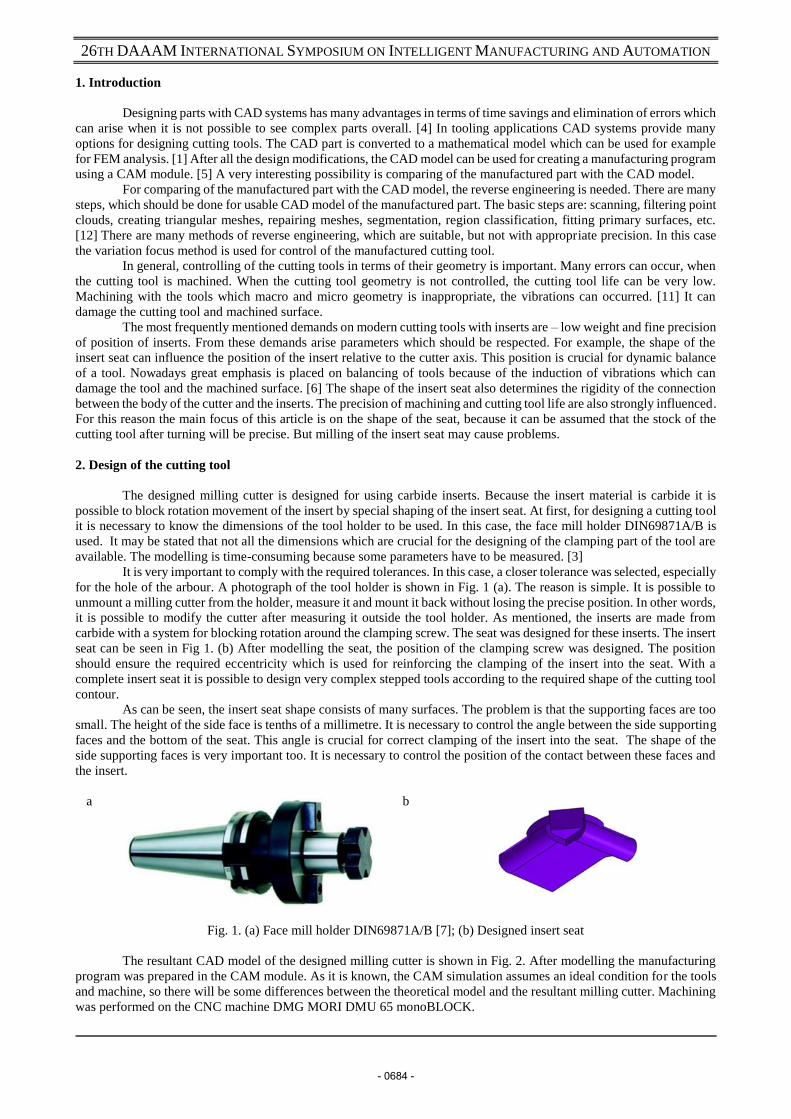
It is very important to comply with the required tolerances. In this case, a closer tolerance was selected, especially
for the hole of the arbour. A photograph of the tool holder is shown in Fig. 1 (a). The reason is simple. It is possible to
unmount a milling cutter from the holder, measure it and mount it back without losing the precise position. In other words,
it is possible to modify the cutter after measuring it outside the tool holder. As mentioned, the inserts are made from
carbide with a system for blocking rotation around the clamping screw. The seat was designed for these inserts. The insert
seat can be seen in Fig 1. (b) After modelling the seat, the position of the clamping screw was designed. The position
should ensure the required eccentricity which is used for reinforcing the clamping of the insert into the seat. With a
complete insert seat it is possible to design very complex stepped tools according to the required shape of the cutting tool
contour.
As can be seen, the insert seat shape consists of many surfaces. The problem is that the supporting faces are too
small. The height of the side face is tenths of a millimetre. It is necessary to control the angle between the side supporting
faces and the bottom of the seat. This angle is crucial for correct clamping of the insert into the seat. The shape of the
side supporting faces is very important too. It is necessary to control the position of the contact between these faces and
the insert.
a
b
Fig. 1. (a) Face mill holder DIN69871A/B [7]; (b) Designed insert seat
The resultant CAD model of the designed milling cutter is shown in Fig. 2. After modelling the manufacturing
program was prepared in the CAM module. As it is known, the CAM simulation assumes an ideal condition for the tools
and machine, so there will be some differences between the theoretical model and the resultant milling cutter. Machining
was performed on the CNC machine DMG MORI DMU 65 monoBLOCK.
- 0684 -
26TH DAAAM INTERNATIONAL SYMPOSIUM ON INTELLIGENT MANUFACTURING AND AUTOMATION
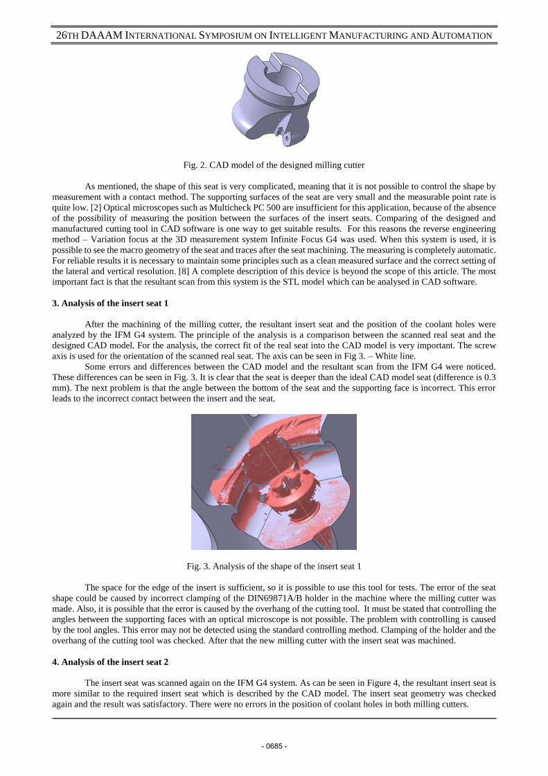
Fig. 2. CAD model of the designed milling cutter
As mentioned, the shape of this seat is very complicated, meaning that it is not possible to control the shape by
measurement with a contact method. The supporting surfaces of the seat are very small and the measurable point rate is
quite low. [2] Optical microscopes such as Multicheck PC 500 are insufficient for this application, because of the absence
of the possibility of measuring the position between the surfaces of the insert seats. Comparing of the designed and
manufactured cutting tool in CAD software is one way to get suitable results. For this reasons the reverse engineering
method – Variation focus at the 3D measurement system Infinite Focus G4 was used. When this system is used, it is
possible to see the macro geometry of the seat and traces after the seat machining. The measuring is completely automatic.
For reliable results it is necessary to maintain some principles such as a clean measured surface and the correct setting of
the lateral and vertical resolution. [8] A complete description of this device is beyond the scope of this article. The most
important fact is that the resultant scan from this system is the STL model which can be analysed in CAD software.
3. Analysis of the insert seat 1
After the machining of the milling cutter, the resultant insert seat and the position of the coolant holes were
analyzed by the IFM G4 system. The principle of the analysis is a comparison between the scanned real seat and the
designed CAD model. For the analysis, the correct fit of the real seat into the CAD model is very important. The screw
axis is used for the orientation of the scanned real seat. The axis can be seen in Fig 3. – White line.
Some errors and differences between the CAD model and the resultant scan from the IFM G4 were noticed.
These differences can be seen in Fig. 3. It is clear that the seat is deeper than the ideal CAD model seat (difference is 0.3
mm). The next problem is that the angle between the bottom of the seat and the supporting face is incorrect. This error
leads to the incorrect contact between the insert and the seat.
Fig. 3. Analysis of the shape of the insert seat 1
The space for the edge of the insert is sufficient, so it is possible to use this tool for tests. The error of the seat
shape could be caused by incorrect clamping of the DIN69871A/B holder in the machine where the milling cutter was
made. Also, it is possible that the error is caused by the overhang of the cutting tool. It must be stated that controlling the
angles between the supporting faces with an optical microscope is not possible. The problem with controlling is caused
by the tool angles. This error may not be detected using the standard controlling method. Clamping of the holder and the
overhang of the cutting tool was checked. After that the new milling cutter with the insert seat was machined.
4. Analysis of the insert seat 2
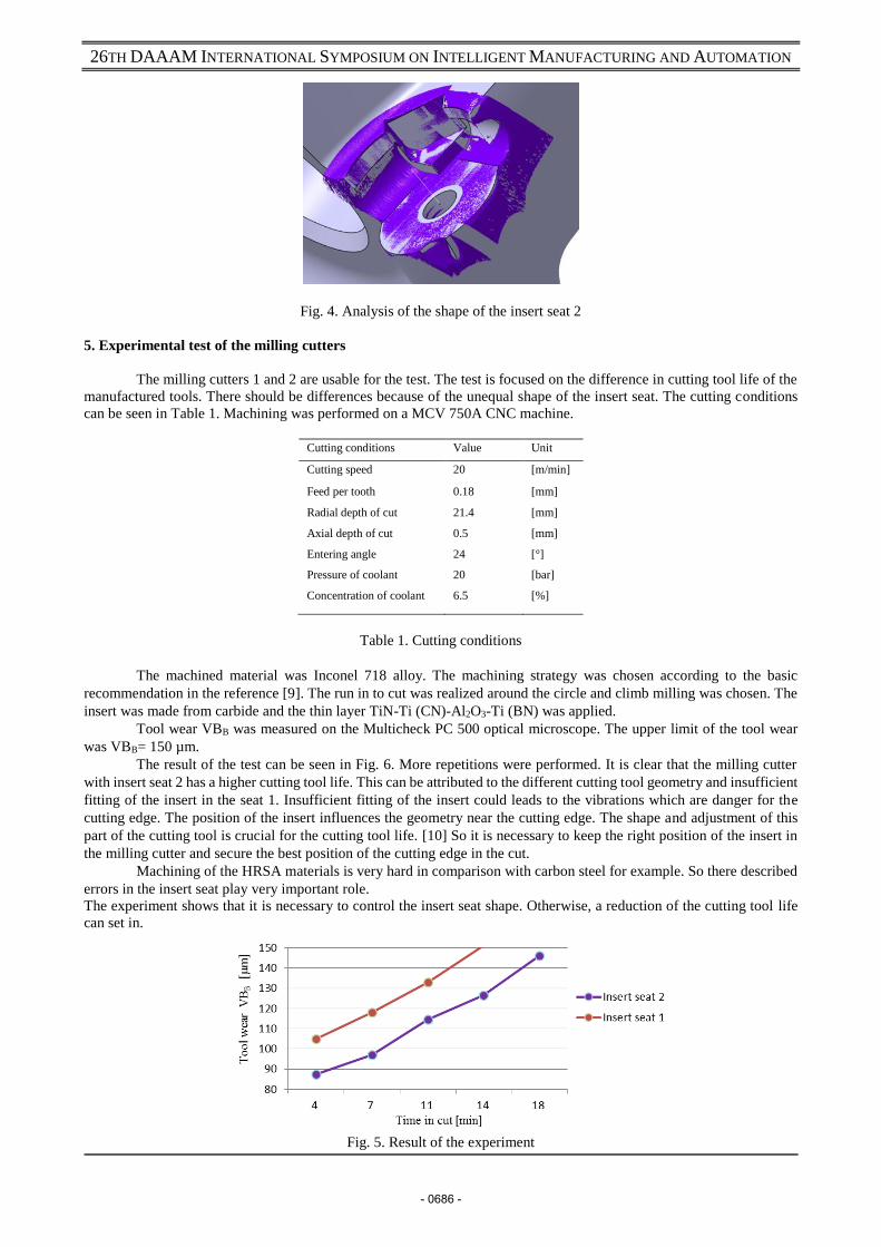
The insert seat was scanned again on the IFM G4 system. As can be seen in Figure 4, the resultant insert seat is
more similar to the required insert seat which is described by the CAD model. The insert seat geometry was checked
again and the result was satisfactory. There were no errors in the position of coolant holes in both milling cutters.
- 0685 -
26TH DAAAM INTERNATIONAL SYMPOSIUM ON INTELLIGENT MANUFACTURING AND AUTOMATION
Fig. 4. Analysis of the shape of the insert seat 2
5. Experimental test of the milling cutters
The milling cutters 1 and 2 are usable for the test. The test is focused on the difference in cutting tool life of the
manufactured tools. There should be differences because of the unequal shape of the insert seat. The cutting conditions
can be seen in Table 1. Machining was performed on a MCV 750A CNC machine.
Cutting conditions Value Unit
Cutting speed 20 [m/min]
Feed per tooth 0.18 [mm]
Radial depth of cut
Axial depth of cut
Entering angle
Pressure of coolant
Concentration of coolant
21.4
0.5
24
20
6.5
[mm]
[mm]
[°]
[bar]
[%]
Table 1. Cutting conditions
The machined material was Inconel 718 alloy. The machining strategy was chosen according to the basic
recommendation in the reference [9]. The run in to cut was realized around the circle and climb milling was chosen. The
insert was made from carbide and the thin layer TiN-Ti (CN)-Al2O3-Ti (BN) was applied.
Tool wear VBB was measured on the Multicheck PC 500 optical microscope. The upper limit of the tool wear
was VBB= 150 µm.
The result of the test can be seen in Fig. 6. More repetitions were performed. It is clear that the milling cutter
with insert seat 2 has a higher cutting tool life. This can be attributed to the different cutting tool geometry and insufficient
fitting of the insert in the seat 1. Insufficient fitting of the insert could leads to the vibrations which are danger for the
cutting edge. The position of the insert influences the geometry near the cutting edge. The shape and adjustment of this
part of the cutting tool is crucial for the cutting tool life. [10] So it is necessary to keep the right position of the insert in
the milling cutter and secure the best position of the cutting edge in the cut.
Machining of the HRSA materials is very hard in comparison with carbon steel for example. So there described
errors in the insert seat play very important role.
The experiment shows that it is necessary to control the insert seat shape. Otherwise, a reduction of the cutting tool life
can set in.
Fig. 5. Result of the experiment
- 0686 -
26TH DAAAM INTERNATIONAL SYMPOSIUM ON INTELLIGENT MANUFACTURING AND AUTOMATION
6. Conclusion
Nowadays, designing and manufacturing of cutting tools is at a high standard. This article offers the possibility
of using modern technology which can be used for controlling the very complex parts of cutting tools and matching
between the designed and the real shape.
Analysis of two insert seats was proved. It was found that control of monitored parameters would be problematic
when using the standard technology. The analysis was performed and differences between the ideal and real seats were
eliminated. After this an experiment for machining with the designed tools was performed. The experiment shows that it
is very important to analyze the insert seat because of the different cutting tool life. The main problem of this system is
that the correct fitting of the STL model to the designed CAD model is still up to the worker and depends on his/her
knowledge of working with STL models. Working with STL models is not the same as with a standard CAD model.
Future research in this field will focus on the possibilities of the automatic fitting of scanned STL models into designed
CAD models. The main advantage of this method is the complete control of the shape of the real part in one step.
7. Acknowledgements
The present contribution has been prepared under project LO1502 ‘Development of the Regional Technological
Institute‘ under the auspices of the National Sustainability Programme I of the Ministry of Education of the Czech
Republic aimed to support research, experimental development and innovation.
8. References
[1] B. Micieta, M. Jancusova, P. Macek, J. Durica (2014). Designing Measuring Equipment and Camera Systems in Manufacturing, Chapter 41 in DAAAM International Scientific Book 2014, pp.509-524, B. Katalinic (Ed.), Published by DAAAM International, ISBN 978-3-901509-98-8, ISSN 1726-9687, Vienna, Austria DOI:10.2507/daaam.scibook.2014.41
[2] L.M. Galantucci, M. Pesce, F. Lavecchia, A powerful scanning methodology for 3D measurements of small parts with complex surfaces and sub millimeter-sized features, based on close range photogrammetry, Precision Engineering, Available online 7 August 2015, ISSN 0141-6359, http://dx.doi.org/10.1016/j.precisioneng.2015.07.010. (http://www.sciencedirect.com/science/article/pii/S0141635915001440)
[3] X. Zhang, W.-M. Tsang, M. Mori, K. Yamazaki, Automatic 3D model reconstruction of cutting tools from a single camera, Computers in Industry, Volume 61, Issue 7, September 2010, Pages 711-726, ISSN 0166-3615, http://dx.doi.org/10.1016/j.compind.2010.05.009. (http://www.sciencedirect.com/science/article/pii/S0166361510000825)
[4] CADCEA ltd., Benefits of 3D CAD Design http://www.3d-cadcea.co.uk/html/benefits.htm
[5] B. Huang, C. Xu, R. Huang, S. Zhang, An automatic 3D CAD model errors detection method of aircraft structural part for NC machining, Journal of Computational Design and Engineering, Available online 23 June 2015, ISSN 2288-4300, http://dx.doi.org/10.1016/j.jcde.2015.06.008. (http://www.sciencedirect.com/science/article/pii/S2288430015000573)
[6] Modern Machine Shop, Cutting Tool Considerations For High Speed Machininghttp://www.mmsonline.com/articles/cutting-tool-considerations-for-high-speed-machining
[7] Toolholders. KFH. Bartoos. http://www.bartools.hu/img/katalogus/kfh_din69871.pdf
[8] I. Česáková, M. Zetek, V. Švarc, Evaluation of Cutting Tool Parameters, Procedia Engineering, Volume 69, 2014, Pages 1105-1114, ISSN 1877-7058, http://dx.doi.org/10.1016/j.proeng.2014.03.098. (http://www.sciencedirect.com/science/article/pii/S1877705814003440)
[9] Sandvik. Application Guide. [Online] C-2920:034 US/01 © AB Sandvik Coromant 2010.08, http://www.sandvik.coromant.com/sitecollectiondocuments/downloads/global/technical%20guides/en-us/c-2920-034.pdf
[10] M. Zetek, I. Česáková, V. Švarc, Increasing Cutting Tool Life when Machining Inconel 718, Procedia Engineering, Volume 69, 2014, Pages 1115-1124, ISSN 1877-7058, http://dx.doi.org/10.1016/j.proeng.2014.03.099. (http://www.sciencedirect.com/science/article/pii/S1877705814003452)
[11] L.T. Tunç, E. Budak, Effect of cutting conditions and tool geometry on process damping in machining, International Journal of Machine Tools and Manufacture, Volume 57, June 2012, Pages 10-19, ISSN 0890-6955, http://dx.doi.org/10.1016/j.ijmachtools.2012.01.009. (http://www.sciencedirect.com/science/article/pii/S089069551200020X)
[12] I. Kovács, T. Várady, P. Salvi, Applying geometric constraints for perfecting CAD models in reverse engineering, Graphical Models, Available online 16 June 2015, ISSN 1524-0703, http://dx.doi.org/10.1016/j.gmod.2015.06.002. (http://www.sciencedirect.com/science/article/pii/S1524070315000211)
- 0687 -