Models: TT300, TT350, TT400, TT500 and TG310 · APPLICATIONS MANUAL Danfoss Turbocor Compressors...
70
APPLICATIONS MANUAL Danfoss Turbocor Compressors Inc. M-AP-001-EN Rev. K August 2014 TWIN-TURBINE CENTRIFUGAL COMPRESSORS Models: TT300, TT350, TT400, TT500 and TG310
Transcript of Models: TT300, TT350, TT400, TT500 and TG310 · APPLICATIONS MANUAL Danfoss Turbocor Compressors...
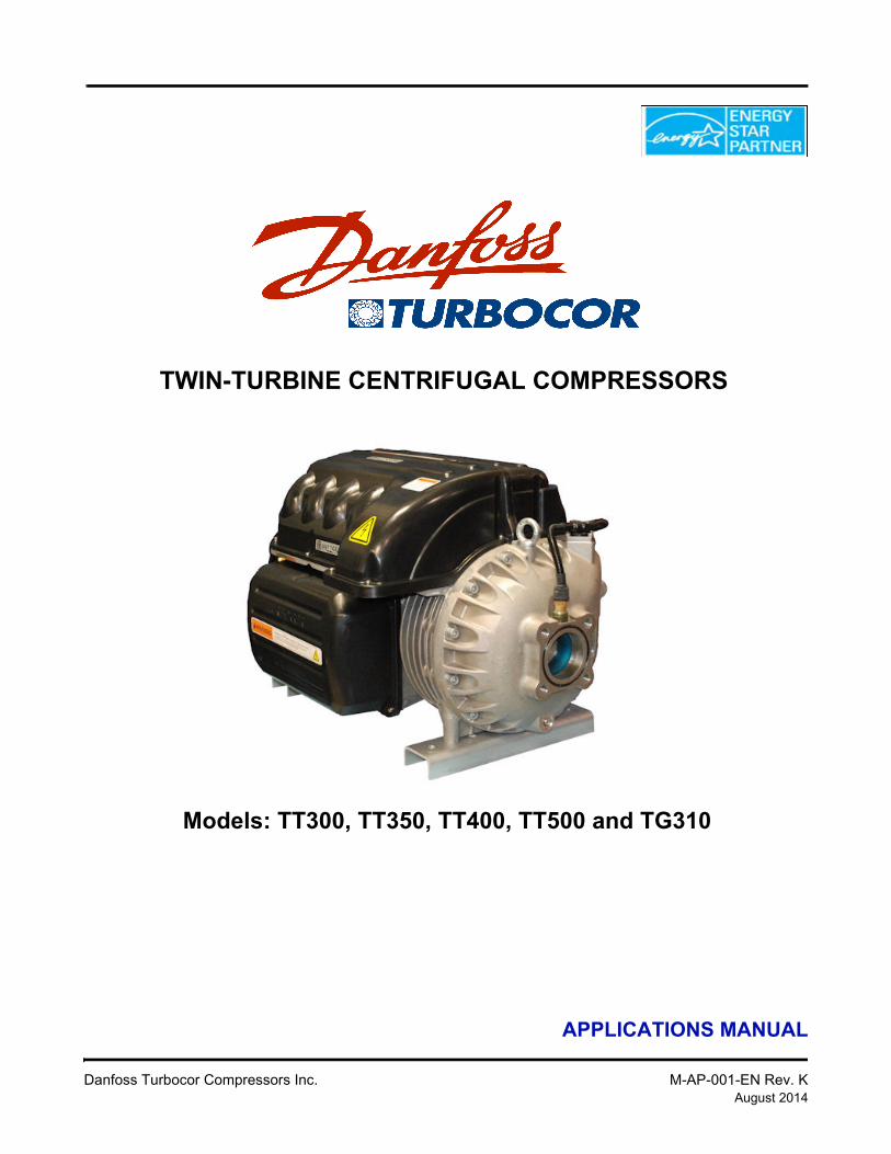
TWIN-TURBINE CENTRIFUGAL COMPRESSORS
APPLICATIONS MANUAL
Danfoss Turbocor Compressors Inc. M-AP-001-EN Rev. KAugust 2014
Models: TT300, TT350, TT400, TT500 and TG310

This Page Left Intentionally Blank
Applications Manual
Proprietary Notice
Copyright, Limitations of Liability and Revision Rights
This publication contains proprietary information to Danfoss Turbocor Compressors, Inc. (DTC). This publication is protected under the Copyright laws of the United States of America (USA) and most other countries. This work is owned by DTC, and was published as of the most recent revision of this publication, as indicated on the Title page of this document. This document is for the use DTC customers and prospective customers only. Any use beyond that is prohibited.
Tests have demonstrated that equipment produced according to the guidelines provided in this manual will function properly, however DTC cannot guarantee the equipment to work in every physical, hardware or software environment.
The guidelines provided in this manual are provided "AS-IS" without any warranty of any kind, either express or implied, including, without limitation, any implied warranties of condition, uninterrupted use, merchantability, fitness for a particular purpose.
In no event shall DTC be liable for direct, indirect, special, incidental or consequential damages arising out of the manufacture, use, or the inability to manufacture or use information contained in this manual, even if advised of the possibility of such damages. In particular, DTC is not responsible for any costs, including but not limited to those incurred as a result of lost profits or revenue, loss of damage or equipment, loss of computer programs, loss of data, the costs to substitute these, or any claims by third parties. In any event, DTC's total aggregate liability for all damages of any kind and type (regardless of whether based in contract or tort) shall not exceed the purchase price of this product.
DTC reserves the right to revise the publication at any time and to make changes to its contents without prior notice or any obligation to notify former or present users of such revisions or changes.
Danfoss Turbocor Compressors Inc.1769 East Paul Dirac DriveTallahassee, Florida 32310USAPhone 1-850-504-4800Fax 1-850-575-2126www.turbocor.com
* Subject to change without notice.
* Danfoss Turbocor’s commitment to excellence ensures continuous product improvements.
Danfoss Turbocor Compressors Inc. 3M-AP-001-EN Rev. K

4 Danfoss Turbocor Compressors Inc.M-AP-001-EN Rev. K
Applications Manual
1 Introduction................................................................................................................................................... 71.1 Scope............................................................................................................................................. 7
2 Safety Summary............................................................................................................................................ 73 Product Certification..................................................................................................................................... 74 General Specifications .................................................................................................................................. 8
4.1 Maximum Pressure ....................................................................................................................... 84.2 Suction Pressure Limits ................................................................................................................ 94.3 Construction.................................................................................................................................. 94.4 Refrigerant Type ......................................................................................................................... 10
4.4.1 TG310 ................................................................................................................................ 104.5 Environment................................................................................................................................ 104.6 Noise ........................................................................................................................................... 104.7 Outdoor Installations................................................................................................................... 10
5 Accessories ................................................................................................................................................. 116 Product Application .................................................................................................................................... 11
6.1 TG310 ......................................................................................................................................... 117 Economizer Option ..................................................................................................................................... 118 Compressor Current Limit and Operating Range Settings ......................................................................... 129 Operating Envelopes................................................................................................................................... 1410 Minimum Unloading Capacity ................................................................................................................. 1911 Control Logic Guidelines For Multiple Compressors .............................................................................. 22
11.1 Staging of the Compressors ...................................................................................................... 2212 Electrical Specifications............................................................................................................................ 23
12.1 Supply Voltage and Frequency................................................................................................. 2312.2 Disconnects ............................................................................................................................... 2312.3 AC Input Line/Power Electronic Component Protection ......................................................... 2412.4 Power Line Contactor ............................................................................................................... 2512.5 CE Compliance and EMI/EMC Filtering ................................................................................. 2512.6 Surge Protection........................................................................................................................ 2512.7 Harmonic Filtering (IEEE 519) ................................................................................................ 2512.8 Grounding (Earth) Connection Guidelines ............................................................................... 2612.9 Equipment Panel ....................................................................................................................... 2712.10 Mains Input Cable Specification............................................................................................. 27
13 Control Interface Wiring........................................................................................................................... 2813.1 Control Wiring Connection Guidelines .................................................................................... 2913.2 Interface Cable.......................................................................................................................... 3013.3 Compressor I/O Board Mounting Details ................................................................................. 31
14 Piping Considerations .............................................................................................................................. 3215 Environmental Considerations.................................................................................................................. 33
15.1 Humidity ................................................................................................................................... 3315.2 Vibration ................................................................................................................................... 33
16 Shipping Considerations ........................................................................................................................... 3316.1 Vibration ................................................................................................................................... 33
17 Physical Data ............................................................................................................................................ 3417.1 Mounting Base.......................................................................................................................... 3417.2 Clearance .................................................................................................................................. 3417.3 Valve Flanges ........................................................................................................................... 36
18 Guide Specifications ................................................................................................................................. 43
Danfoss Turbocor Compressors Inc. 5M-AP-001-EN Rev. K
18.1 General...................................................................................................................................... 4318.2 Refrigerant ................................................................................................................................ 4318.3 Compressor Bearings................................................................................................................ 4318.4 Capacity Control ....................................................................................................................... 4318.5 Compressor Motor .................................................................................................................... 4318.6 Compressor Electronics ............................................................................................................ 43
18.6.1 Ancillary Devices ............................................................................................................ 4419 System Design Guidelines ........................................................................................................................ 45
19.1 General Requirements............................................................................................................... 4519.2 Economizer Option ................................................................................................................... 4719.3 Motor/Electronics Cooling Requirements ................................................................................ 4719.4 Electrical Requirements............................................................................................................ 4719.5 Application-Specific Requirements.......................................................................................... 48
19.5.1 Medium Evaporating Temperature Application (TT300) ............................................... 4819.5.2 Air-Cooled Systems/Chillers ........................................................................................... 4819.5.3 Inverted Start ................................................................................................................... 4919.5.4 Multiple Compressors on Common Circuit Using
One Evaporator and One Condenser ............................................................................ 4919.5.5 Packaged Air-Side With DX-Type Evaporator and Multiple Evaporator Coils ............. 50
20 Sample Refrigeration Circuits................................................................................................................... 5121 Sound Power Specifications ..................................................................................................................... 56
21.1 TT300 Sound Power Measurements......................................................................................... 5621.1.1 Results ............................................................................................................................. 56
21.2 TT400 Sound Power Measurements......................................................................................... 5821.2.1 Results ............................................................................................................................. 58
Appendix A: Acronyms ................................................................................................................................... 61
6 Danfoss Turbocor Compressors Inc.M-AP-001-EN Rev. K
Applications Manual
1 IntroductionThis Application Manual is intended to inform application data/ procedures specific to Turbocor compressors. It is not intended to inform on fundamental safety, refrigeration and electrical design skills. It is assumed and presumed that persons using this manual will be appropriately certified and have detailed knowledge, experience and skills in respect to designing for and working with high pressure refrigerants and medium voltage electrical components (to 1 KV high power AC & DC) as well as complex control systems.
Some potential safety situations may not be foreseen or covered in the manual. Danfoss Turbocor Compressors, Inc. (DTC) expects personnel using this manual and working on DTC compressors to be familiar with, and carry out, all safe work practices necessary to ensure safety for personnel and equipment.
1.1 Scope
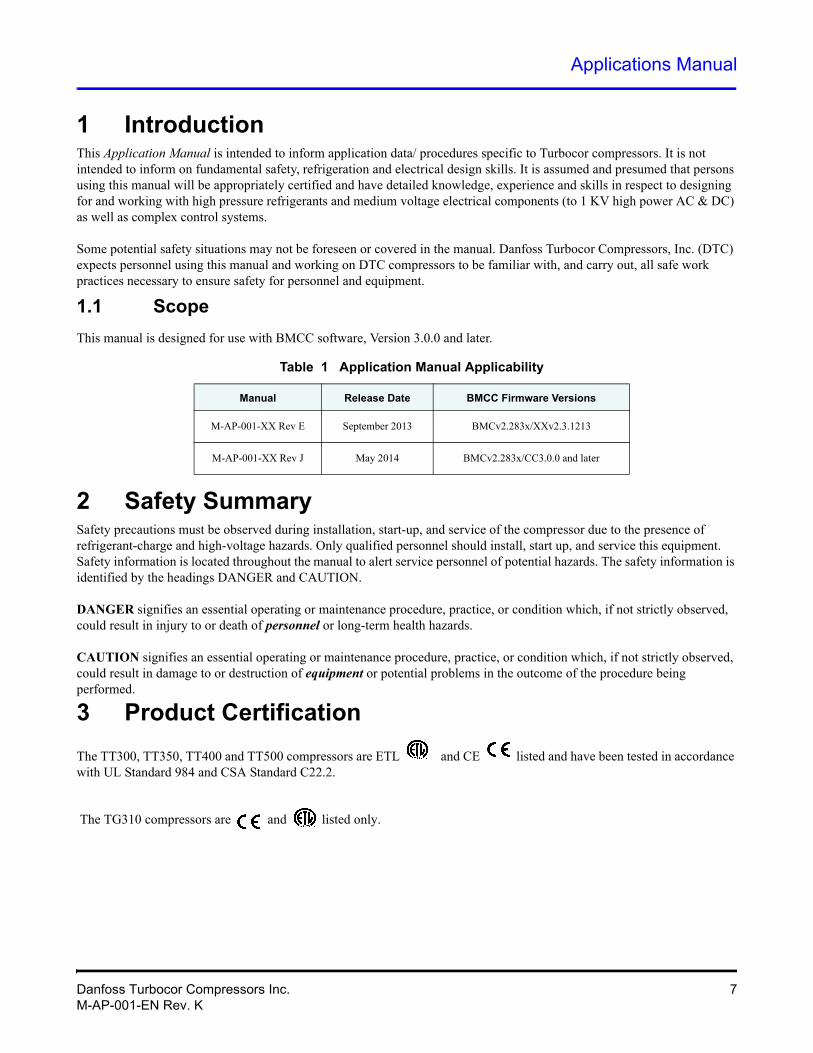
This manual is designed for use with BMCC software, Version 3.0.0 and later.
Table 1 Application Manual Applicability
Manual Release Date BMCC Firmware Versions
2 Safety SummarySafety precautions must be observed during installation, start-up, and service of the compressor due to the presence of refrigerant-charge and high-voltage hazards. Only qualified personnel should install, start up, and service this equipment. Safety information is located throughout the manual to alert service personnel of potential hazards. The safety information is identified by the headings DANGER and CAUTION.
DANGER signifies an essential operating or maintenance procedure, practice, or condition which, if not strictly observed, could result in injury to or death of personnel or long-term health hazards.
CAUTION signifies an essential operating or maintenance procedure, practice, or condition which, if not strictly observed, could result in damage to or destruction of equipment or potential problems in the outcome of the procedure being performed.
3 Product Certification
The TT300, TT350, TT400 and TT500 compressors are ETL and CE listed and have been tested in accordance with UL Standard 984 and CSA Standard C22.2.
The TG310 compressors are and listed only.
M-AP-001-XX Rev E September 2013 BMCv2.283x/XXv2.3.1213
M-AP-001-XX Rev J May 2014 BMCv2.283x/CC3.0.0 and later
Danfoss Turbocor Compressors Inc. 7M-AP-001-EN Rev. K
4 General SpecificationsPlease refer to Section 18 for a detailed description of the specifications.
4.1 Maximum Pressure
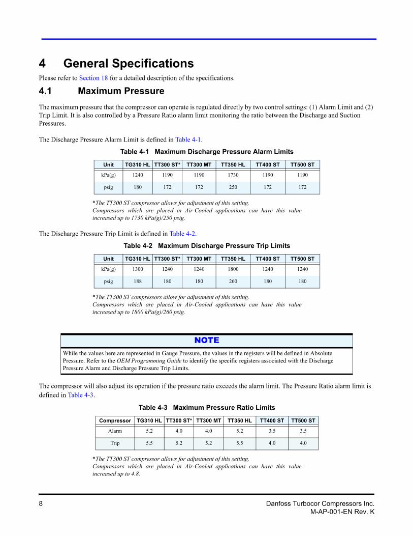
The maximum pressure that the compressor can operate is regulated directly by two control settings: (1) Alarm Limit and (2) Trip Limit. It is also controlled by a Pressure Ratio alarm limit monitoring the ratio between the Discharge and Suction Pressures.
The Discharge Pressure Alarm Limit is defined in Table 4-1.
Table 4-1 Maximum Discharge Pressure Alarm Limits
Unit TG310 HL TT300 ST* TT300 MT TT350 HL TT400 ST TT500 ST
Table 4-2 Maximum Discharge Pressure Trip Limits
Unit TG310 HL TT300 ST* TT300 MT TT350 HL TT400 ST TT500 ST
*The TT300 ST compressor allows for adjustment of this setting.Compressors which are placed in Air-Cooled applications can have this value increased up to 1730 kPa(g)/250 psig.
The Discharge Pressure Trip Limit is defined in Table 4-2.
*The TT300 ST compressors allow for adjustment of this setting.Compressors which are placed in Air-Cooled applications can have this value increased up to 1800 kPa(g)/260 psig.
The compressor will also adjust its operation if the pressure ratio exceeds the alarm limit. The Pressure Ratio alarm limit is defined in Table 4-3.
Table 4-3 Maximum Pressure Ratio Limits
Compressor TG310 HL TT300 ST* TT300 MT TT350 HL TT400 ST TT500 ST
*The TT300 ST compressor allows for adjustment of this setting.Compressors which are placed in Air-Cooled applications can have this value increased up to 4.8.
kPa(g) 1240 1190 1190 1730 1190 1190
psig 180 172 172 250 172 172
kPa(g) 1300 1240 1240 1800 1240 1240
psig 188 180 180 260 180 180
NOTEWhile the values here are represented in Gauge Pressure, the values in the registers will be defined in Absolute Pressure. Refer to the OEM Programming Guide to identify the specific registers associated with the Discharge Pressure Alarm and Discharge Pressure Trip Limits.
Alarm 5.2 4.0 4.0 5.2 3.5 3.5
Trip 5.5 5.2 5.2 5.5 4.0 4.0
8 Danfoss Turbocor Compressors Inc.M-AP-001-EN Rev. K
Applications Manual
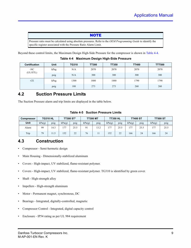
Table 4-4 Maximum Design High-Side Pressure
Certification Unit TG310 TT300 TT350 TT400 TTT500
Beyond these control limits, the Maximum Design High-Side Pressure for the compressor is shown in Table 4-4.
4.2 Suction Pressure Limits
The Suction Pressure alarm and trip limits are displayed in the table below.
4.3 Construction
• Compressor - Semi-hermetic design
• Main Housing - Dimensionally-stabilized aluminum
• Covers - High-impact, UV stabilized, flame-resistant polymer.
• Covers - High-impact, UV stabilized, flame-resistant polymer. TG310 is identified by green cover.
• Shaft - High-strength alloy
• Impellers - High-strength aluminum
• Motor - Permanent magnet, synchronous, DC
• Bearings - Integrated, digitally-controlled, magnetic
• Compressor Control - Integrated, digital capacity control
• Enclosure - IP54 rating as per UL 984 requirement
NOTEPressure ratio must be calculated using absolute pressures. Refer to the OEM Programming Guide to identify the specific register associated with the Pressure Ratio Alarm Limit.
-NC(UL/ETL)
kPag N/A 2070 2070 2070 2070
psig N/A 300 300 300 300
-CE kPag 1300 1880 1880 1790 1790
psig 188 273 273 260 260
Table 4-5 Suction Pressure Limits
Compressor TG310 HL TT300 ST* TT300 MT TT350 HL TT400 ST TT500 ST
Unit kPa(g) psig kPa(g) psig kPa(g) psig kPa(g) psig kPa(g) psig kPa(g) psig
Alarm 99 14.3 177 25.5 91 13.2 177 25.5 177 25.5 177 25.5
Trip 79 11.5 152 22 76 11 152 22 166 24 166 24
Danfoss Turbocor Compressors Inc. 9M-AP-001-EN Rev. K
4.4 Refrigerant Type
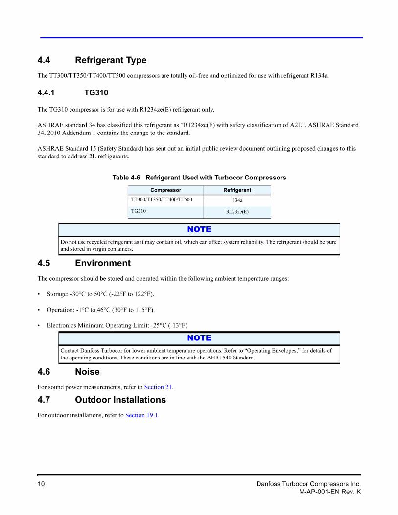
The TT300/TT350/TT400/TT500 compressors are totally oil-free and optimized for use with refrigerant R134a.
4.4.1 TG310
The TG310 compressor is for use with R1234ze(E) refrigerant only.
ASHRAE standard 34 has classified this refrigerant as “R1234ze(E) with safety classification of A2L”. ASHRAE Standard 34, 2010 Addendum 1 contains the change to the standard.
ASHRAE Standard 15 (Safety Standard) has sent out an initial public review document outlining proposed changes to this standard to address 2L refrigerants.
4.5 Environment
The compressor should be stored and operated within the following ambient temperature ranges:
• Storage: -30°C to 50°C (-22°F to 122°F).
• Operation: -1°C to 46°C (30°F to 115°F).
• Electronics Minimum Operating Limit: -25°C (-13°F)
NOTE
4.6 Noise
For sound power measurements, refer to Section 21.
4.7 Outdoor Installations
For outdoor installations, refer to Section 19.1.
Table 4-6 Refrigerant Used with Turbocor Compressors
Compressor Refrigerant
TT300/TT350/TT400/TT500 134a
TG310 R123ze(E)
NOTEDo not use recycled refrigerant as it may contain oil, which can affect system reliability. The refrigerant should be pure and stored in virgin containers.
Contact Danfoss Turbocor for lower ambient temperature operations. Refer to “Operating Envelopes,” for details of the operating conditions. These conditions are in line with the AHRI 540 Standard.
10 Danfoss Turbocor Compressors Inc.M-AP-001-EN Rev. K
Applications Manual
5 AccessoriesRefer to the Accessories Manual for product descriptions and specifications.
6 Product ApplicationTurbocor compressors are to be used in stationary installations only. For any moving or marine applications, contact DTC.
6.1 TG310
It is the responsibility of the OEM to ensure that proper safety protocols are in place and that the chiller system has been designed in a manner that is compliant with all local codes and regulatory requirements governing the user of these types of refrigerants. OEMs must also ensure compliance with the requirements stated in the manufacturer’s Material Safety Data Sheet (MSDS) for R1234ze(E), and that other system components are compatible with the refrigerant, giving special attention to elastomers and seals.
7 Economizer OptionTurbocor compressors use two stage centrifugal compression with interstage port availability. This feature provides advantages of capacity and efficiency improvement by installing and operating an economizer. The improvements in efficiency and capacity are a result of further sub-cooling of the liquid refrigerant. Two types of economizer arrangements can be used: sub-cooler or flash tank. See Figure 34 and Figure 35. Refrigerant must enter the compressor in “gas” state into the economizer port. Care must be taken to ensure that no liquid enters the compressor.
Danfoss Turbocor Compressors Inc. 11M-AP-001-EN Rev. K
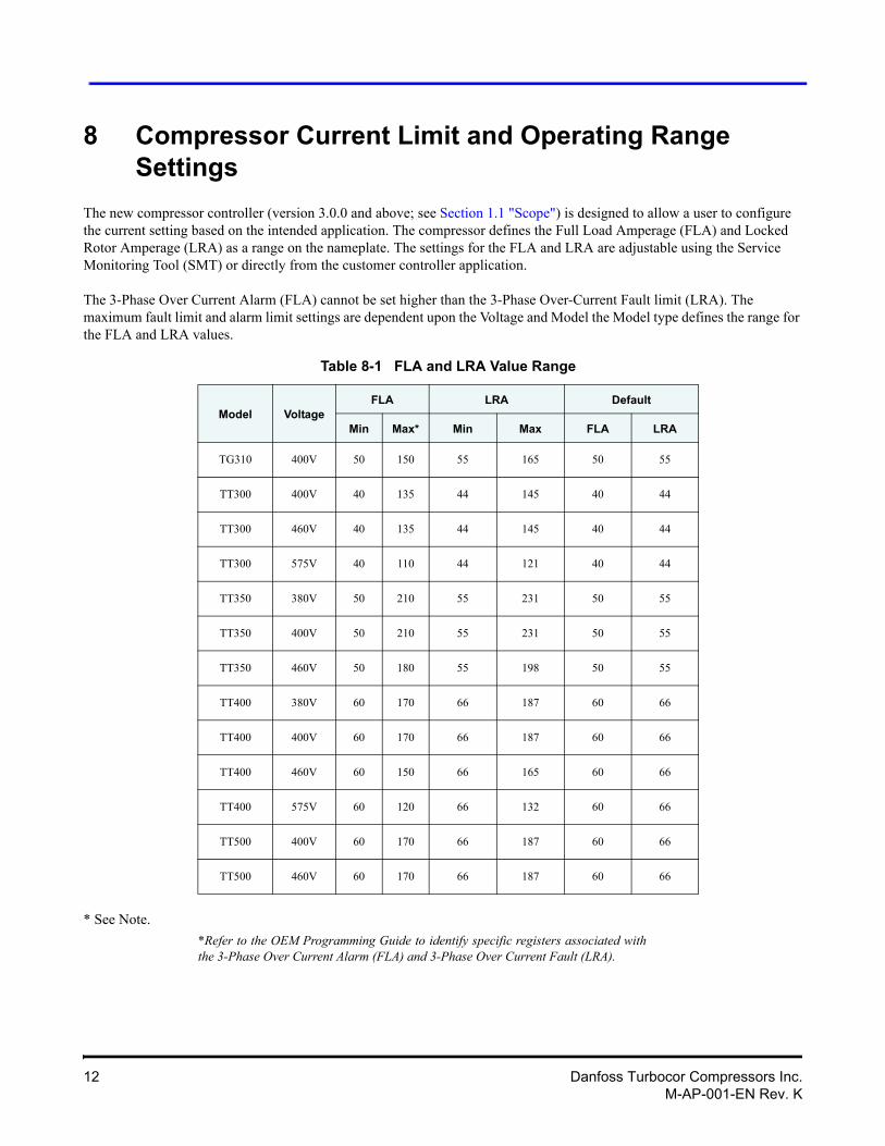
8 Compressor Current Limit and Operating Range Settings
The new compressor controller (version 3.0.0 and above; see Section 1.1 "Scope") is designed to allow a user to configure the current setting based on the intended application. The compressor defines the Full Load Amperage (FLA) and Locked Rotor Amperage (LRA) as a range on the nameplate. The settings for the FLA and LRA are adjustable using the Service Monitoring Tool (SMT) or directly from the customer controller application.
The 3-Phase Over Current Alarm (FLA) cannot be set higher than the 3-Phase Over-Current Fault limit (LRA). The maximum fault limit and alarm limit settings are dependent upon the Voltage and Model the Model type defines the range for the FLA and LRA values.
Table 8-1 FLA and LRA Value Range
Model VoltageFLA LRA Default
Min Max* Min Max FLA LRA
* See Note.
*Refer to the OEM Programming Guide to identify specific registers associated with the 3-Phase Over Current Alarm (FLA) and 3-Phase Over Current Fault (LRA).
TG310 400V 50 150 55 165 50 55
TT300 400V 40 135 44 145 40 44
TT300 460V 40 135 44 145 40 44
TT300 575V 40 110 44 121 40 44
TT350 380V 50 210 55 231 50 55
TT350 400V 50 210 55 231 50 55
TT350 460V 50 180 55 198 50 55
TT400 380V 60 170 66 187 60 66
TT400 400V 60 170 66 187 60 66
TT400 460V 60 150 66 165 60 66
TT400 575V 60 120 66 132 60 66
TT500 400V 60 170 66 187 60 66
TT500 460V 60 170 66 187 60 66
12 Danfoss Turbocor Compressors Inc.M-AP-001-EN Rev. K
Applications Manual
TT300 compressors used in air cooled applications may also require adjustment to the Discharge Pressure trip and alarm settings as well as the Pressure Ratio alarm setting.
See Section 4.1 "Maximum Pressure" for more information on setting these values.
NOTEIt is possible to adjust the FLA Maximum to equal the LRA Minimum, but this is not recommended. A difference should be maintained of no less than 10% between the FLA and LRA in order to allow the compressor to adjust prior to tripping on over current.
Failure to adjust the 3-Phase Current Alarm and Fault limits from the factory settings could result in limitation of the compressor performance.
! • • • CAUTION! • • •Adjustment to the 3-Phase Over Current Alarm and Fault Limits cannot exceed the electrical rating for the disconnect, fuses or wire size. Power configuration must be in accordance with applicable local, national and international building codes (such as NEC/CEC).
! • • • WARNING! • • •
Danfoss Turbocor Compressors Inc. 13M-AP-001-EN Rev. K
9 Operating Envelopes
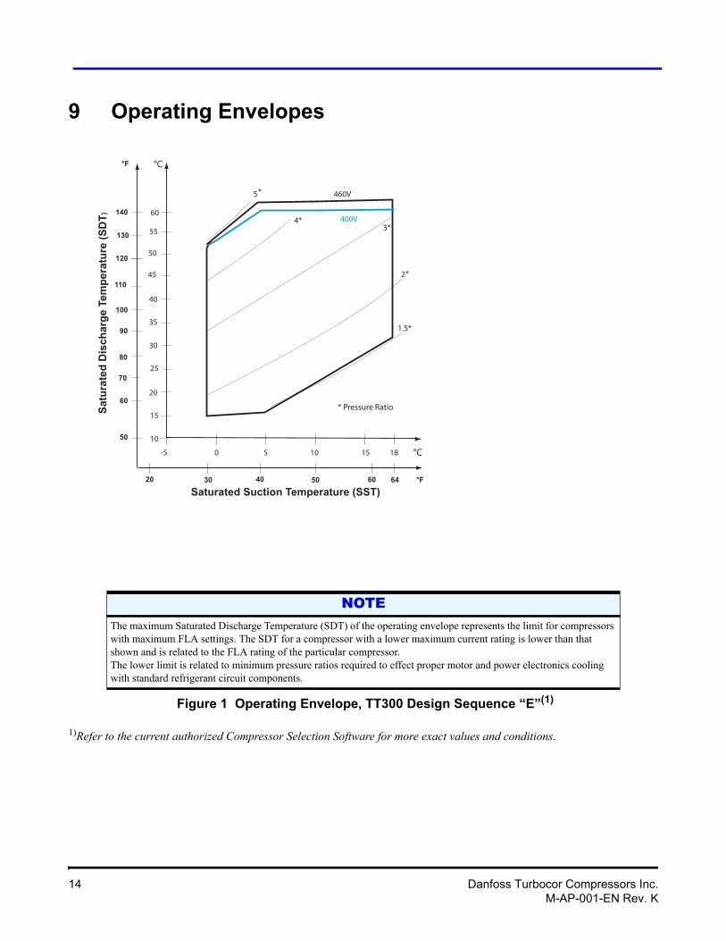
Figure 1 Operating Envelope, TT300 Design Sequence “E”(1)
1)Refer to the current authorized Compressor Selection Software for more exact values and conditions.
NOTEThe maximum Saturated Discharge Temperature (SDT) of the operating envelope represents the limit for compressors with maximum FLA settings. The SDT for a compressor with a lower maximum current rating is lower than that shown and is related to the FLA rating of the particular compressor. The lower limit is related to minimum pressure ratios required to effect proper motor and power electronics cooling with standard refrigerant circuit components.
0 5 10-5 18
10
20
30
40
50
55
°C
°C
20 30 40 50 64
50
60
70
80
90
130
°F
°F
1.5*
2*
3*4*
15
60
45
35
25
15
100
110
120
Saturated Suction Temperature (SST)
Satu
rate
d D
isch
arge
Tem
pera
ture
(SD
T)
* Pressure Ratio
140400V
460V
60
5*
14 Danfoss Turbocor Compressors Inc.M-AP-001-EN Rev. K
Applications Manual
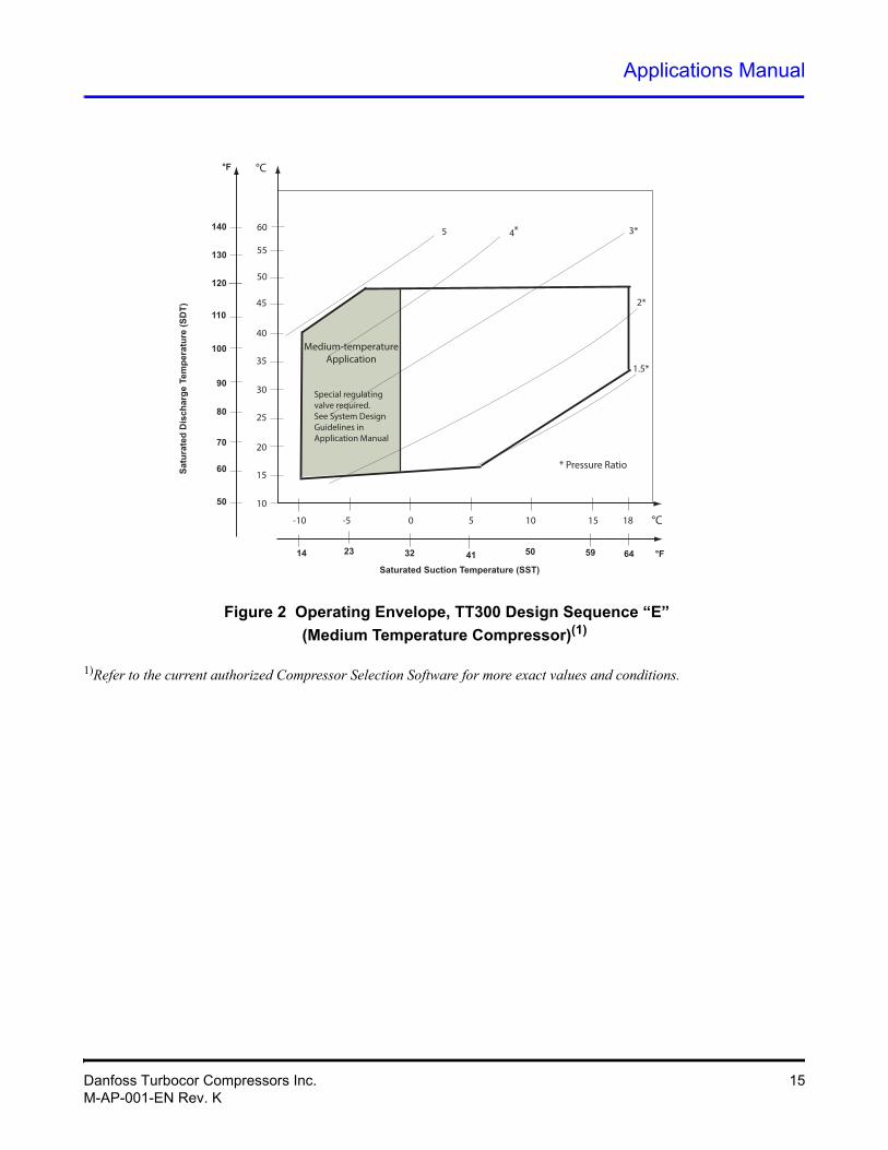
Figure 2 Operating Envelope, TT300 Design Sequence “E”
(Medium Temperature Compressor)(1)
1)Refer to the current authorized Compressor Selection Software for more exact values and conditions.
0 5 10-10 -5 18
10
20
30
40
50
55
°C
°C
14 23 32 41 64
50
60
70
80
90
130
°F
°F
1.5*
2*
3*45
15
50
45
35
25
15
100
110
120
Saturated Suction Temperature (SST)
Satu
rate
d D
isch
arge
Tem
pera
ture
(SD
T)
* Pressure Ratio
140 60
Special regulating valve required.See System Design Guidelines in Application Manual
59
*
Medium-temperature Application
Danfoss Turbocor Compressors Inc. 15M-AP-001-EN Rev. K
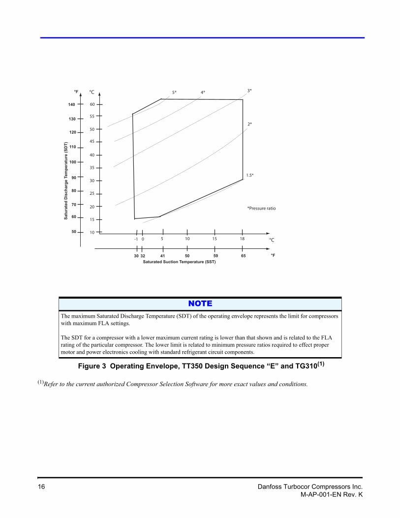
Figure 3 Operating Envelope, TT350 Design Sequence “E” and TG310(1)
(1)Refer to the current authorized Compressor Selection Software for more exact values and conditions.
NOTEThe maximum Saturated Discharge Temperature (SDT) of the operating envelope represents the limit for compressors with maximum FLA settings.
The SDT for a compressor with a lower maximum current rating is lower than that shown and is related to the FLA rating of the particular compressor. The lower limit is related to minimum pressure ratios required to effect proper motor and power electronics cooling with standard refrigerant circuit components.
0 5 10 1810
20
30
40
50
55
°C
°C
30 32 41 50
50
60
70
80
90
°F
°F
1.5*
2*
3*4*5*
15
65
45
35
25
15
100
110
120
Saturated Suction Temperature (SST)
Satu
rate
d D
isch
arge
Tem
pera
ture
(SD
T)
60
130
140
-1
59
*Pressure ratio
16 Danfoss Turbocor Compressors Inc.M-AP-001-EN Rev. K
Applications Manual
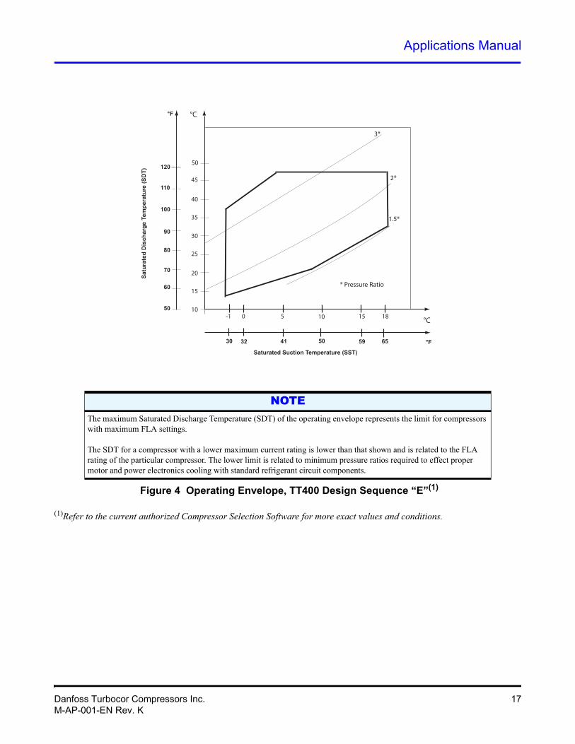
Figure 4 Operating Envelope, TT400 Design Sequence “E”(1)
(1)Refer to the current authorized Compressor Selection Software for more exact values and conditions.
NOTEThe maximum Saturated Discharge Temperature (SDT) of the operating envelope represents the limit for compressors with maximum FLA settings.
The SDT for a compressor with a lower maximum current rating is lower than that shown and is related to the FLA rating of the particular compressor. The lower limit is related to minimum pressure ratios required to effect proper motor and power electronics cooling with standard refrigerant circuit components.
0 5 10-1 1810
20
30
40
50
°C
°C
30 32 41 59
50
60
70
80
90
°F
°F
15
50
45
35
25
15
100
110
120
Saturated Suction Temperature (SST)
Satu
rate
d D
isch
arge
Tem
pera
ture
(SD
T)
* Pressure Ratio
1.5*
2*
3*
65
Danfoss Turbocor Compressors Inc. 17M-AP-001-EN Rev. K
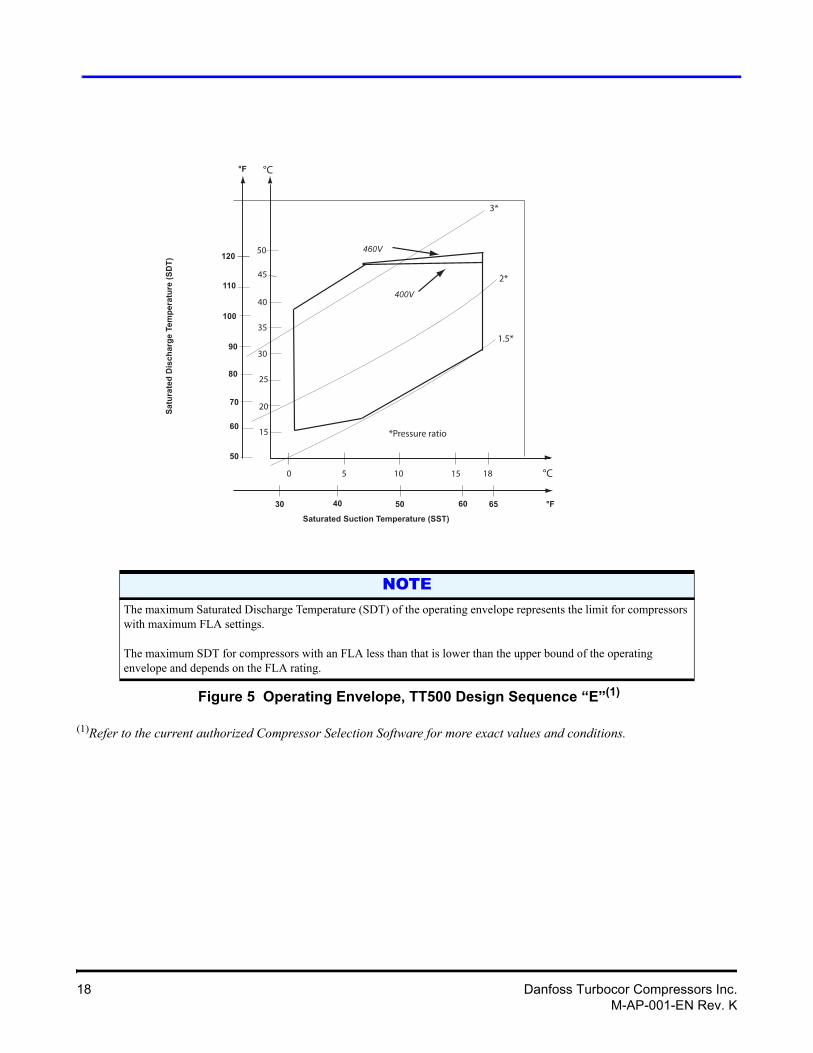
Figure 5 Operating Envelope, TT500 Design Sequence “E”(1)
(1)Refer to the current authorized Compressor Selection Software for more exact values and conditions.
NOTEThe maximum Saturated Discharge Temperature (SDT) of the operating envelope represents the limit for compressors with maximum FLA settings.
The maximum SDT for compressors with an FLA less than that is lower than the upper bound of the operating envelope and depends on the FLA rating.
0 5 10 18
20
30
40
50
°C
°C
30 40 50 65
50
60
70
80
90
°F
°F
1.5*
2*
3*
15
60
45
35
25
15
100
110
120
Saturated Suction Temperature (SST)
Satu
rate
d D
isch
arge
Tem
pera
ture
(SD
T)
*Pressure ratio
400V
460V
18 Danfoss Turbocor Compressors Inc.M-AP-001-EN Rev. K
Applications Manual
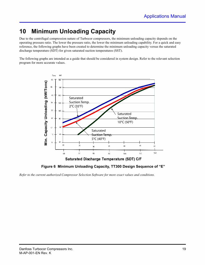
10 Minimum Unloading CapacityDue to the centrifugal compression nature of Turbocor compressors, the minimum unloading capacity depends on the operating pressure ratio. The lower the pressure ratio, the lower the minimum unloading capability. For a quick and easy reference, the following graphs have been created to determine the minimum unloading capacity versus the saturated discharge temperature (SDT) for given saturated suction temperatures (SST).
The following graphs are intended as a guide that should be considered in system design. Refer to the relevant selection program for more accurate values.
Figure 6 Minimum Unloading Capacity, TT300 Design Sequence of “E”
Refer to the current authorized Compressor Selection Software for more exact values and conditions.
Danfoss Turbocor Compressors Inc. 19M-AP-001-EN Rev. K
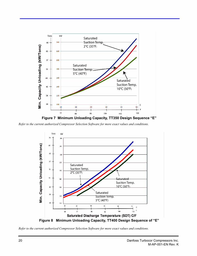
Figure 7 Minimum Unloading Capacity, TT350 Design Sequence “E”
Refer to the current authorized Compressor Selection Software for more exact values and conditions.
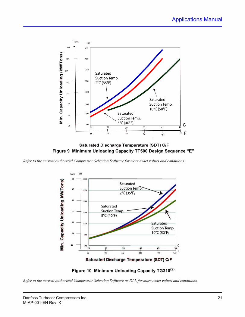
Figure 8 Minimum Unloading Capacity, TT400 Design Sequence of “E”
Refer to the current authorized Compressor Selection Software for more exact values and conditions.
20 Danfoss Turbocor Compressors Inc.M-AP-001-EN Rev. K
Applications Manual
Figure 9 Minimum Unloading Capacity TT500 Design Sequence “E”
Refer to the current authorized Compressor Selection Software for more exact values and conditions.
Figure 10 Minimum Unloading Capacity TG310(2)
Refer to the current authorized Compressor Selection Software or DLL for more exact values and conditions.
Danfoss Turbocor Compressors Inc. 21M-AP-001-EN Rev. K
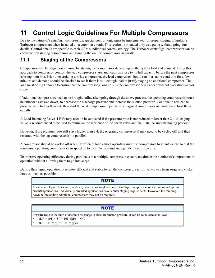
11 Control Logic Guidelines For Multiple CompressorsDue to the nature of centrifugal compression, special control logic must be implemented for proper staging of multiple Turbocor compressors when installed on a common circuit. This section is intended only as a guide without going into details. Control details are specific to each OEM's individual control strategy. The Turbocor centrifugal compressors can be controlled by staging compressors and running the on line compressors in parallel.
11.1 Staging of the Compressors
Compressors can be staged one-by-one by staging the compressors depending on the system load and demand. Using this approach to compressor control, the lead compressor starts and loads up close to its full capacity before the next compressor is brought on line. Prior to energizing any lag compressor, the lead compressor should run in a stable condition for a few minutes and demand should be checked to see if there is still enough load to justify staging an additional compressor. The load must be high enough to ensure that the compressor(s) online plus the compressor being added will not over shoot and/or surge.
If additional compressors need to be brought online after going through the above process, the operating compressor(s) must be unloaded (slowed down) to decrease the discharge pressure and increase the suction pressure. Continue to reduce the pressure ratio to less than 2.4, then start the next compressor. Operate all energized compressors in parallel and load them equally.
A Load Balancing Valve (LBV) may need to be activated if the pressure ratio is not reduced to lower than 2.4. A staging valve is recommended to be used to minimize the influence of the check valve and facilitate the smooth staging process.
However, if the pressure ratio still stays higher than 2.4, the operating compressor(s) may need to be cycled off, and then restarted with the lag compressor(s) in parallel.
A compressor should be cycled off when insufficient load causes operating multiple compressors to go into surge so that the remaining operating compressors can speed up to meet the demand and operate more efficiently.
To improve operating efficiency during part loads in a multiple-compressor system, maximize the number of compressors in operation without allowing them to go into surge.
During the staging operation, it is more efficient and stable to run the compressors in full vane away from surge and choke lines as much as possible.
NOTEThese control guidelines are specifically written for single-circuited (multiple compressors on a common refrigerant circuit) applications. Individually circuited applications have similar staging requirements. However, the ramping down before adding additional compressors may not be required.
NOTEPressure ratio is the ratio of absolute discharge to absolute suction pressure. It can be calculated as follows:• (DP + 101) / (SP + 101) (kPa) OR• (DP + 14.7) / (SP + 14.7) (psi)
22 Danfoss Turbocor Compressors Inc.M-AP-001-EN Rev. K
Applications Manual
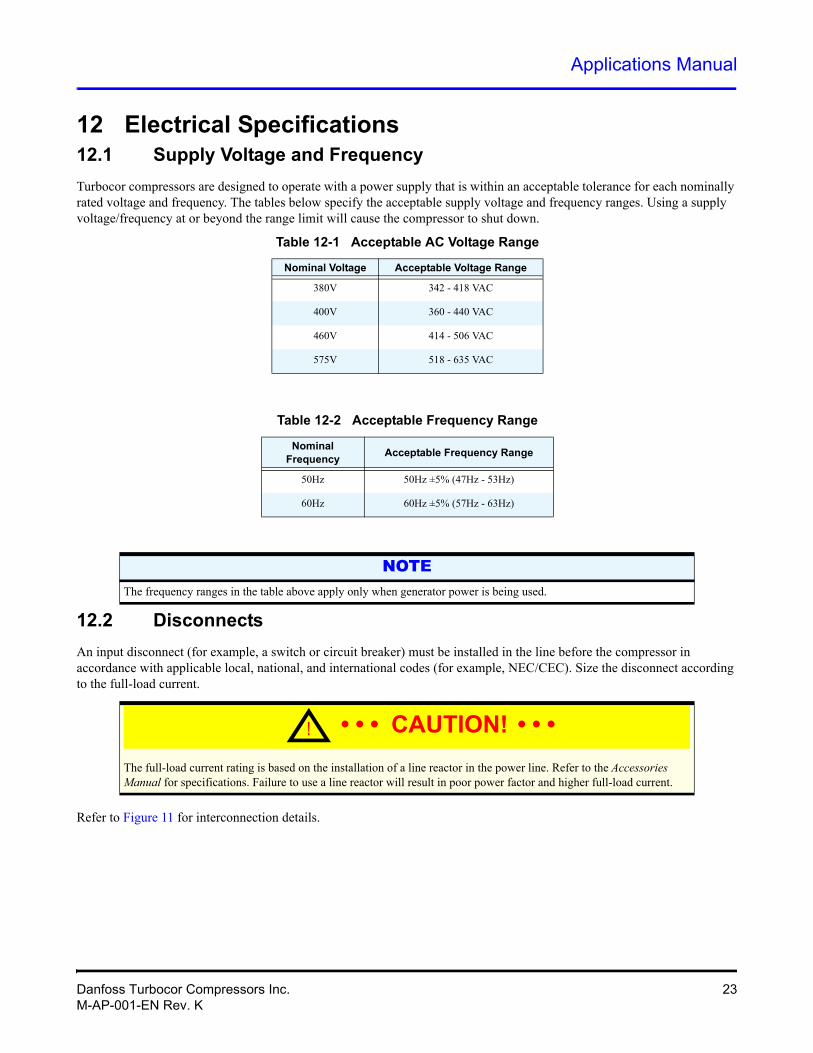
12 Electrical Specifications12.1 Supply Voltage and Frequency
Turbocor compressors are designed to operate with a power supply that is within an acceptable tolerance for each nominally rated voltage and frequency. The tables below specify the acceptable supply voltage and frequency ranges. Using a supply voltage/frequency at or beyond the range limit will cause the compressor to shut down.
Table 12-1 Acceptable AC Voltage Range
Nominal Voltage Acceptable Voltage Range
Table 12-2 Acceptable Frequency Range
Nominal Frequency
Acceptable Frequency Range
NOTE
12.2 Disconnects
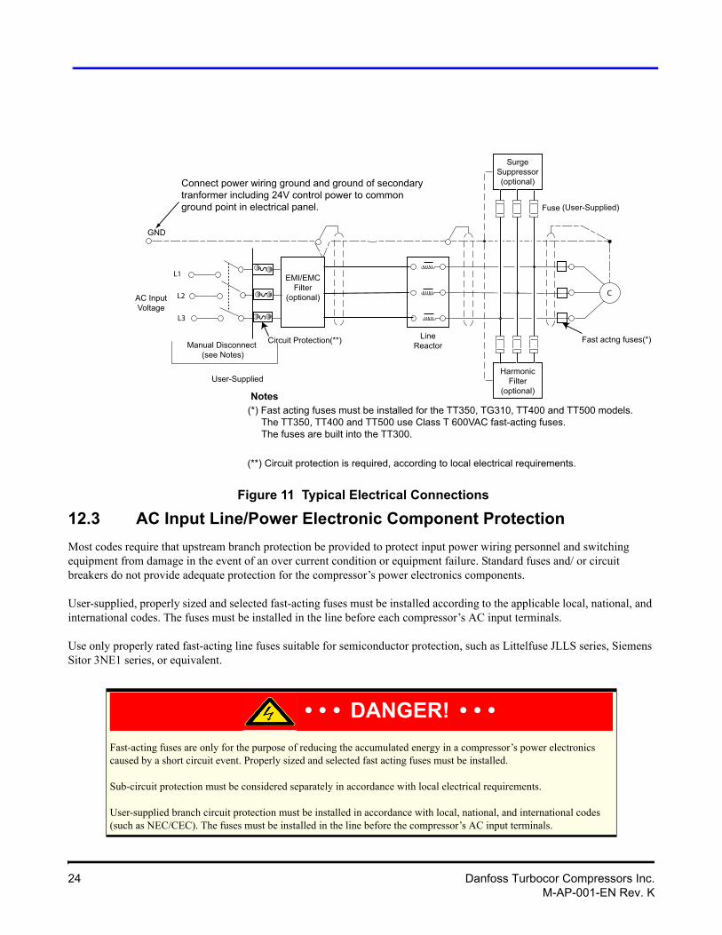
An input disconnect (for example, a switch or circuit breaker) must be installed in the line before the compressor in accordance with applicable local, national, and international codes (for example, NEC/CEC). Size the disconnect according to the full-load current.
The full-load current rating is based on the installation of a line reactor in the power line. Refer to the Accessories Manual for specifications. Failure to use a line reactor will result in poor power factor and higher full-load current.
Refer to Figure 11 for interconnection details.
380V 342 - 418 VAC
400V 360 - 440 VAC
460V 414 - 506 VAC
575V 518 - 635 VAC
50Hz 50Hz ±5% (47Hz - 53Hz)
60Hz 60Hz ±5% (57Hz - 63Hz)
The frequency ranges in the table above apply only when generator power is being used.
! • • • CAUTION! • • •
Danfoss Turbocor Compressors Inc. 23M-AP-001-EN Rev. K
AC InputVoltage
Manual Disconnect (see Notes)
LineReactorCircuit Protection(**)
User-Supplied
C
GND
L1
L2
L3
HarmonicFilter
(optional)
(*) Fast acting fuses must be installed for the TT350, TG310, TT400 and TT500 models. The TT350, TT400 and TT500 use Class T 600VAC fast-acting fuses. The fuses are built into the TT300.
EMI/EMCFilter
(optional)
SurgeSuppressor(optional)
Fuse (User-Supplied)
(**) Circuit protection is required, according to local electrical requirements.
Connect power wiring ground and ground of secondarytranformer including 24V control power to common ground point in electrical panel.
Notes
Fast actng fuses(*)
SS
S
Figure 11 Typical Electrical Connections
12.3 AC Input Line/Power Electronic Component Protection
Most codes require that upstream branch protection be provided to protect input power wiring personnel and switching equipment from damage in the event of an over current condition or equipment failure. Standard fuses and/ or circuit breakers do not provide adequate protection for the compressor’s power electronics components.
User-supplied, properly sized and selected fast-acting fuses must be installed according to the applicable local, national, and international codes. The fuses must be installed in the line before each compressor’s AC input terminals.
Use only properly rated fast-acting line fuses suitable for semiconductor protection, such as Littelfuse JLLS series, Siemens Sitor 3NE1 series, or equivalent.
• • • DANGER! • • •Fast-acting fuses are only for the purpose of reducing the accumulated energy in a compressor’s power electronics caused by a short circuit event. Properly sized and selected fast acting fuses must be installed.Sub-circuit protection must be considered separately in accordance with local electrical requirements. User-supplied branch circuit protection must be installed in accordance with local, national, and international codes (such as NEC/CEC). The fuses must be installed in the line before the compressor’s AC input terminals.
24 Danfoss Turbocor Compressors Inc.M-AP-001-EN Rev. K
Applications Manual
12.4 Power Line Contactor
The power line contactor is optional. Consult local codes to determine if a contactor is necessary for your application.
12.5 CE Compliance and EMI/EMC Filtering
To address EMI/EMC problems, DTC recommends the installation of a UL-approved EMI/EMC filter device on the input power line. Refer to the Accessories Manual for details.
Although all Turbocor compressors are CE listed, the compliance of the compressor with the EMC directive depends on the use of the CE EMI/EMC filter provided by DTC (see Accessories Manual for further details). If this is not possible because of the nature of your application and/or installation, an alternative component with the same attenuation characteristics must be used to maintain compliance with the EMC Directive. It is the responsibility of the user to maintain compliance with the Directives. Contact a DTC sales representative for more details.
Proper installation of the EMI/EMC filter can have a dramatic effect on overall performance. Although the filter reduces electrical noise on the power lines (conducted emissions), it should be located as close as possible to the compressor to reduce broadcasting of the noise (radiated emissions) from the power lines themselves. The capacitors within the filter short the noise to ground so it is imperative that the filter maintains a good ground. A short, heavy, stranded conductor from the filter chassis to the main ground bus is recommended for top performance. A battery braid, litz wire, or flexible welding cable with many fine strands, is recommended for best grounding performance. The multiple-strand cabling provides more surface area in order to conduct the high frequencies that are on the grounding cable.
Radiation of noise is also a concern for power line routing as it can effectively bypass the filter. Input and output filter leads should be separated by a maximum practical distance within enclosures and should be routed separately in interconnecting conduits when used.
12.6 Surge Protection
All Turbocor compressors have been tested in accordance with IEC Standard 1000-4-4. Electrical Fast Transient/Burst Requirement. For additional protection, a surge suppressor can be installed in parallel with the compressor. It is recommended to install surge suppression in sites that are susceptible to lighting.
12.7 Harmonic Filtering (IEEE 519)
In order to comply with IEEE 519 requirements, DTC recommends the installation of a harmonic filter device in parallel with the compressor as shown in Figure 11.
Danfoss Turbocor Compressors Inc. 25M-AP-001-EN Rev. K
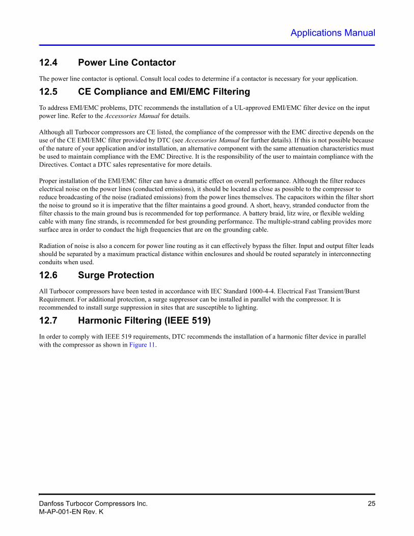
12.8 Grounding (Earth) Connection Guidelines
1. All metal parts should be connected to ground, including the shields of electrical cables.
2. Verify continuity of all ground connections.
3. Ensure solid ground connections (both mechanical and electrical). Connections must be clean, and grease and paint free.
4. At one point, usually the entrance of the power supply panel, all grounds should be connected together (refer to Section 12.9).
From an EMC standpoint, it is best to categorize different types of grounds and treat them independently (see Figure 12):
• Safety ground (Protective Earth [PE]) and shields of mains cables.
• Analog grounds, shielding of interface cables.
• Digital grounds.
• Reference ground (panel doors, backplate, etc.).
Figure 12 Typical Ground Connections
ShieldingI/O Cables
Analog 0VInputs
24V/5VCircuits
Digital Ground *Analog Ground *
Reference Ground
PanelDoors
110V/230VCircuits
Safety Ground (PE)
Shielding(power cables) to motors, etc
* = Isolated from panel.
BackPlate
26 Danfoss Turbocor Compressors Inc.M-AP-001-EN Rev. K
Applications Manual
12.9 Equipment Panel
Normally, the line reactor, EMI/EMC filter(s), and the harmonic filter will be installed in a panel. This could be the same panel where the controls are located. When designing a panel, attention should be given to the following recommendations:
• All metal parts should be properly connected to ensure an electrical connection. Connect panel doors with braided cable.
• Separate panel into sections for power and interface/control functions.
• Keep power cables and interface cables separate. Use metal cable glands for shielded cables.
• The wire-loom going to the panel door should be shielded using a metal-braided hose that is connected to ground at both ends.
• Electrical panel must have a dedicated ground conductor in accordance with relevant electrical codes.
• Verify that the panel ground conductor is sized in accordance with relevant electrical codes.
12.10 Mains Input Cable Specification
The aim of electrical cables is to be a carrier (conductor) for electrical power. The influence of the power source on the environment, or the influence of the environment on the power source, should be such that neither the proper functioning of the compressor nor equipment in its environment is adversely affected. Therefore, DTC advises to use some type of shielded cable for the mains input.
When using shielded cable, select a cable with an effective shield. A cable with an aluminum foil will be far less effective than a specially designed conductive braid. It is best to connect both ends of the cable shield to ground since the shield is not part of the signal path.
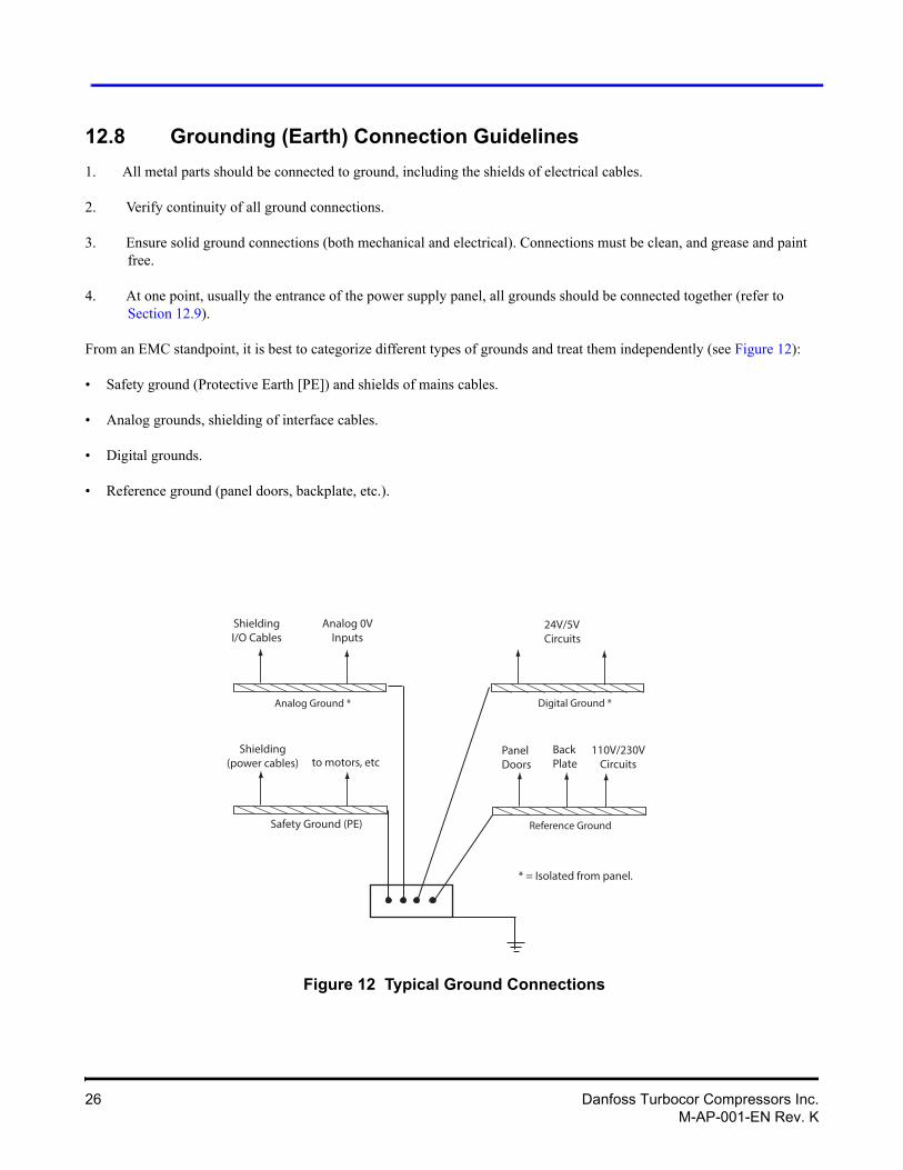
The mains input cable should be CSA, UL, or CE approved, three-wire with a common shield and single ground. The cable must be rated for 90°C (194°F) minimum at the maximum applicable current. It is recommended that the cable be double-jacketed, i.e., teck cable type. Refer to Table 12-3 for cable gland specifications.
NOTEThe installing electrical contractor is responsible for connecting the panel ground to the facility ground in accordance with relevant electrical codes and standards, such as NEC Section 250 in the U.S. or its equivalent for other countries. Special filtering and measuring may be required in installations such as hospitals that are prone to being influenced by other electronic equipment.
Table 12-3 Main Cable Connector Plate Hole Sizes
Actual Size
50.0 mm (1.97”) 63.0 mm (2.48”) 76.2 mm (3.00”) 88.9 mm (3.50”)
Danfoss Turbocor Compressors Inc. 27M-AP-001-EN Rev. K
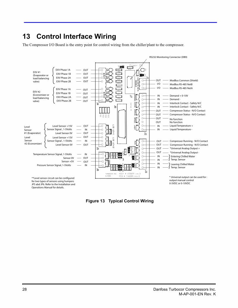
13 Control Interface WiringThe Compressor I/O Board is the entry point for control wiring from the chiller/plant to the compressor.
Figure 13 Typical Control Wiring
OUTI/O
I/O
ININ
ININ
OUT
OUT
OUT
OUT
ININ
OUTOUT
OUT
OUT
ININ
IN
IN
ModBus Common (Shield)
ModBus RS-485 NetB
ModBus RS-485 NetA
Demand + 0-10VDemand -
Interlock Contact - Safety N/CInterlock Contact - Safety N/C
Compressor Status - N/O Contact
Compressor Status - N/O Contact
Entering Chilled Water Temp. Sensor
Leaving Chilled Water Temp. Sensor
EXV Phase 1A
EXV Phase 1B
EXV Phase 2AEXV Phase 2B
EXV #1(Evaporator or load balancing valve)
EXV Phase 1A
EXV Phase 1B
EXV Phase 2AEXV Phase 2B
EXV #2(Economizer orload balancing valve)
Level Sensor +15VSensor Signal , 1-5Volts
Level Sensor 0V
Level Sensor +15VSensor Signal , 1-5Volts
Level Sensor 0V
LevelSensor #1 (Evaporator)
LevelSensor #2 (Economizer)
Liquid Temperature +Liquid Temperature -
Compressor Running - N/O ContactCompressor Running - N/O Contact
Pressure Sensor Signal, 1-5Volts
Sensor +5VSensor 0V
Temperature Sensor Signal, 1-5Volts
*Universal Analog Output +
*Universal Analog Output -
* Universal output can be used for :output manual control0-5VDC or 0-10VDC
RS232 Monitoring Connector (DB9)
J6
J7
J1J2
J4J5
J3
J8
LIQD
TS
PE
ED
STATU
SI/LO
CK
DE
MA
ND
CO
MN
ETA
NE
TB
EX
V1
EX
V2
1A1B
2A2B
1A1B
2A2B
OUT
OUT
OUTOUT
OUT
OUT
OUTOUT
OUT
OUT
OUT
OUT
IN
IN
INOUT
INOUT
RU
NE
NTR
YLE
AVE
AN
ALO
G
FloatFloat
SPA
RE
TS
PAR
E P
No functionNo function
**Level sensor circuit can be configuredfor two types of sensors using humpersJP5 abd JP6. Refer to the Installation andOperations Manual for details.
28 Danfoss Turbocor Compressors Inc.M-AP-001-EN Rev. K
Applications Manual
13.1 Control Wiring Connection Guidelines
To ensure proper control wiring techniques, follow these guidelines:
1. The ground reference of the external circuit connected to the Compressor I/O Board must be at the same potential as the ground reference on the Compressor I/O Board.
2. The Interlock circuit should be voltage-free. For instance, all external contractors/switches must not introduce current into the circuit.
3. Analog outputs (such as Motor Speed) must be received by the external circuit without sending current back to the Compressor I/O Board.
4. All interlock and analog output cables should be shielded with one end of the shield connected to the common analog or digital ground bus. The other end of the shield must not be grounded as this would create a ground loop.
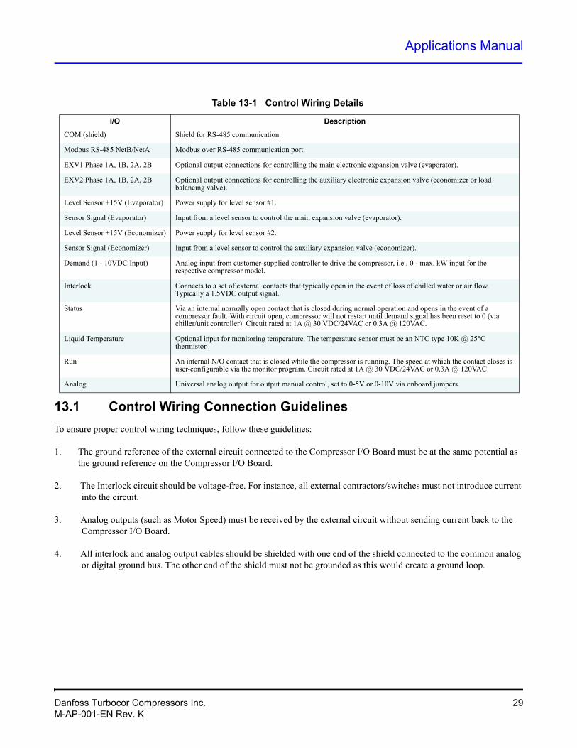
Table 13-1 Control Wiring Details
I/O Description
COM (shield) Shield for RS-485 communication.
Modbus RS-485 NetB/NetA Modbus over RS-485 communication port.
EXV1 Phase 1A, 1B, 2A, 2B Optional output connections for controlling the main electronic expansion valve (evaporator).
EXV2 Phase 1A, 1B, 2A, 2B Optional output connections for controlling the auxiliary electronic expansion valve (economizer or load balancing valve).
Level Sensor +15V (Evaporator) Power supply for level sensor #1.
Sensor Signal (Evaporator) Input from a level sensor to control the main expansion valve (evaporator).
Level Sensor +15V (Economizer) Power supply for level sensor #2.
Sensor Signal (Economizer) Input from a level sensor to control the auxiliary expansion valve (economizer).
Demand (1 - 10VDC Input) Analog input from customer-supplied controller to drive the compressor, i.e., 0 - max. kW input for the respective compressor model.
Interlock Connects to a set of external contacts that typically open in the event of loss of chilled water or air flow. Typically a 1.5VDC output signal.
Status Via an internal normally open contact that is closed during normal operation and opens in the event of a compressor fault. With circuit open, compressor will not restart until demand signal has been reset to 0 (via chiller/unit controller). Circuit rated at 1A @ 30 VDC/24VAC or 0.3A @ 120VAC.
Liquid Temperature Optional input for monitoring temperature. The temperature sensor must be an NTC type 10K @ 25°C thermistor.
Run An internal N/O contact that is closed while the compressor is running. The speed at which the contact closes is user-configurable via the monitor program. Circuit rated at 1A @ 30 VDC/24VAC or 0.3A @ 120VAC.
Analog Universal analog output for output manual control, set to 0-5V or 0-10V via onboard jumpers.
Danfoss Turbocor Compressors Inc. 29M-AP-001-EN Rev. K
13.2 Interface Cable
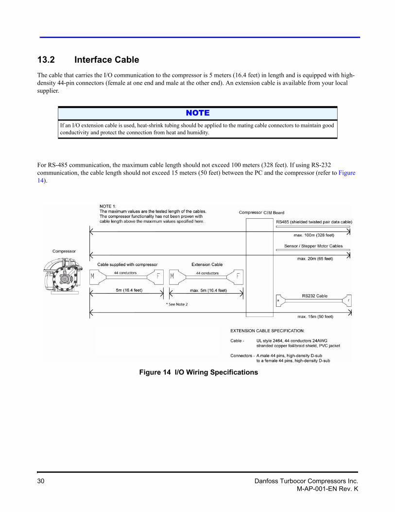
The cable that carries the I/O communication to the compressor is 5 meters (16.4 feet) in length and is equipped with high-density 44-pin connectors (female at one end and male at the other end). An extension cable is available from your local supplier.
For RS-485 communication, the maximum cable length should not exceed 100 meters (328 feet). If using RS-232 communication, the cable length should not exceed 15 meters (50 feet) between the PC and the compressor (refer to Figure 14).
Figure 14 I/O Wiring Specifications
NOTEIf an I/O extension cable is used, heat-shrink tubing should be applied to the mating cable connectors to maintain good conductivity and protect the connection from heat and humidity.
30 Danfoss Turbocor Compressors Inc.M-AP-001-EN Rev. K
Applications Manual
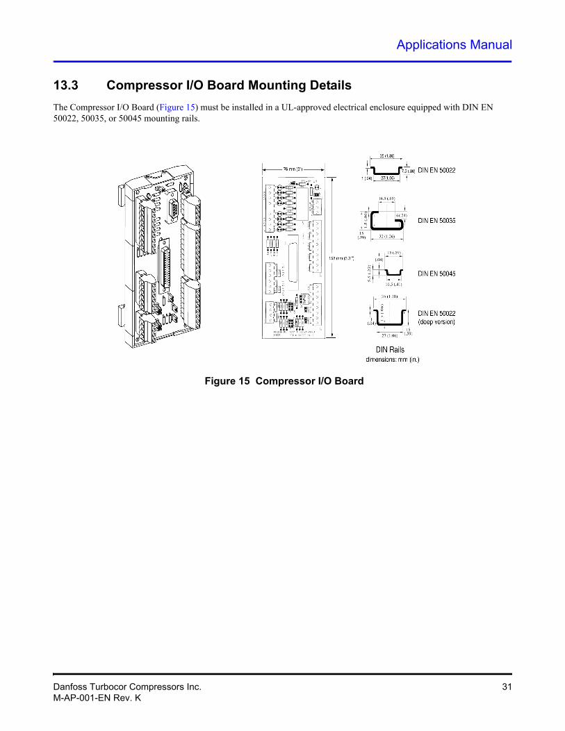
13.3 Compressor I/O Board Mounting Details
The Compressor I/O Board (Figure 15) must be installed in a UL-approved electrical enclosure equipped with DIN EN 50022, 50035, or 50045 mounting rails.
Figure 15 Compressor I/O Board
Danfoss Turbocor Compressors Inc. 31M-AP-001-EN Rev. K
14 Piping ConsiderationsCare should be exercised when selecting pipe sizes as they will vary according to their application. Section 19, “System Design Guidelines,” provides examples of compressor piping arrangements for the most common applications.
The motor-cooling line should be channeled from the liquid line; refer to Section 19.2 for more information. DTC requires the installation of a sight glass and full-flow liquid dryer in the motor-cooling line.
NOTESome applications may require alternative arrangements. Contact DTC for further assistance, if required.
! • • • CAUTION! • • •The discharge line must be fitted with a non-return valve to prevent reverse flow into the discharge port, which can cause damage to compressor components.It is recommended that a strainer be installed in the suction line for the first 100 hours of operation, at 80-100% load, to prevent the ingress of foreign particles into the compressor. IGV and/or impeller damage caused by foreign particles will void the warranty.All pipe work should be carried out in accordance with industry standards. Brazing without the use of nitrogen will result in debris being deposited in the pipes, potentially leading to blockage or damage.Discharge piping should contain a caution label from system manufacturers or compressor installers that the surface is hot.
32 Danfoss Turbocor Compressors Inc.M-AP-001-EN Rev. K
Applications Manual
15 Environmental Considerations15.1 Humidity
If the compressor is installed in a humid environment, drip trays may be required to collect condensate. Insulation should be installed on the suction valve/piping and the end cap as this is where condensation is most likely to form.
It is recommended to fit an End Cap insulator in a humid environment.
15.2 Vibration
External copper piping should be braced to minimize the transfer of vibration to the compressor.
16 Shipping Considerations16.1 Vibration
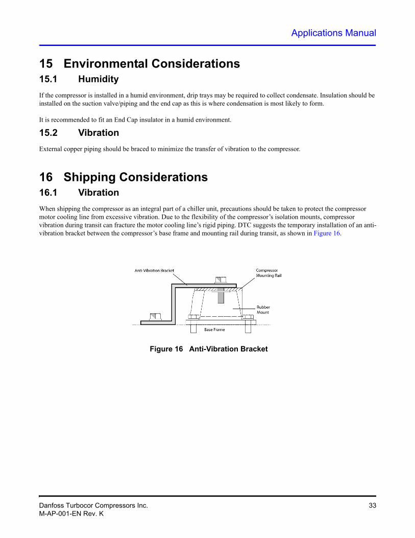
When shipping the compressor as an integral part of a chiller unit, precautions should be taken to protect the compressor motor cooling line from excessive vibration. Due to the flexibility of the compressor’s isolation mounts, compressor vibration during transit can fracture the motor cooling line’s rigid piping. DTC suggests the temporary installation of an anti-vibration bracket between the compressor’s base frame and mounting rail during transit, as shown in Figure 16.
Figure 16 Anti-Vibration Bracket
Danfoss Turbocor Compressors Inc. 33M-AP-001-EN Rev. K
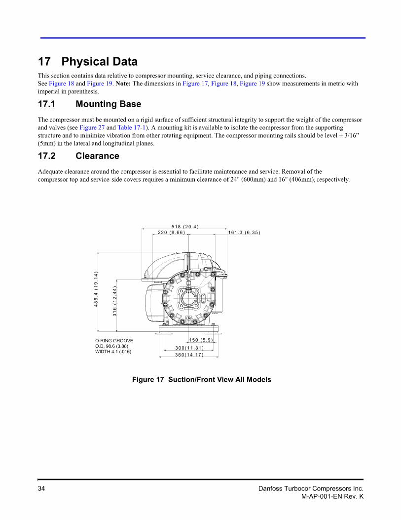
17 Physical DataThis section contains data relative to compressor mounting, service clearance, and piping connections.See Figure 18 and Figure 19. Note: The dimensions in Figure 17, Figure 18, Figure 19 show measurements in metric with imperial in parenthesis.
17.1 Mounting Base
The compressor must be mounted on a rigid surface of sufficient structural integrity to support the weight of the compressor and valves (see Figure 27 and Table 17-1). A mounting kit is available to isolate the compressor from the supporting structure and to minimize vibration from other rotating equipment. The compressor mounting rails should be level ± 3/16” (5mm) in the lateral and longitudinal planes.
17.2 Clearance
Adequate clearance around the compressor is essential to facilitate maintenance and service. Removal of the compressor top and service-side covers requires a minimum clearance of 24" (600mm) and 16" (406mm), respectively.
Figure 17 Suction/Front View All Models
34 Danfoss Turbocor Compressors Inc.M-AP-001-EN Rev. K
Applications Manual
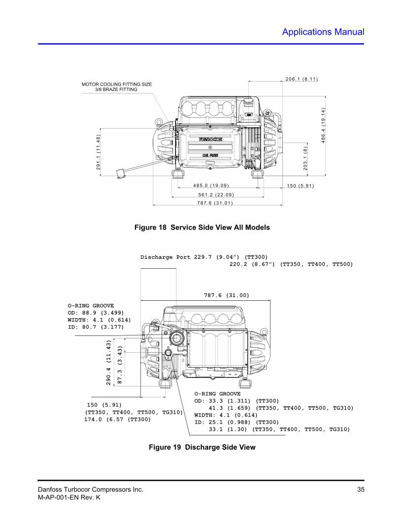
Figure 18 Service Side View All Models
Discharge Port 229.7 (9.04”) (TT300) 220.2 (8.67”) (TT350, TT400, TT500)
O-RING GROOVEOD: 88.9 (3.499)WIDTH: 4.1 (0.614)ID: 80.7 (3.177)
O-RING GROOVEOD: 33.3 (1.311) (TT300) 41.3 (1.659) (TT350, TT400, TT500, TG310)WIDTH: 4.1 (0.614)ID: 25.1 (0.988) (TT300) 33.1 (1.30) (TT350, TT400, TT500, TG310)
150 (5.91)(TT350, TT400, TT500, TG310)174.0 (6.57 (TT300)
290.4 (11.43)
87.3 (3.43)
787.6 (31.00)
Figure 19 Discharge Side View
Danfoss Turbocor Compressors Inc. 35M-AP-001-EN Rev. K
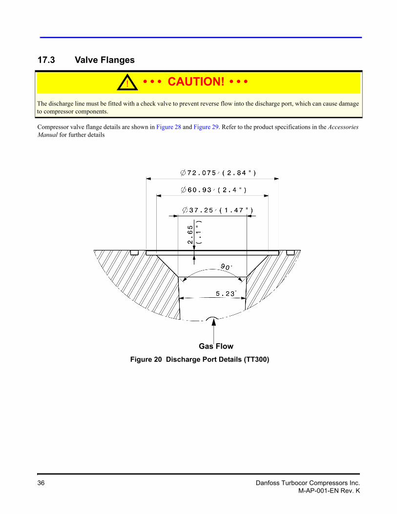
17.3 Valve Flanges
Compressor valve flange details are shown in Figure 28 and Figure 29. Refer to the product specifications in the Accessories Manual for further details
Gas Flow
Figure 20 Discharge Port Details (TT300)
! • • • CAUTION! • • •The discharge line must be fitted with a check valve to prevent reverse flow into the discharge port, which can cause damage to compressor components.
36 Danfoss Turbocor Compressors Inc.M-AP-001-EN Rev. K
Applications Manual
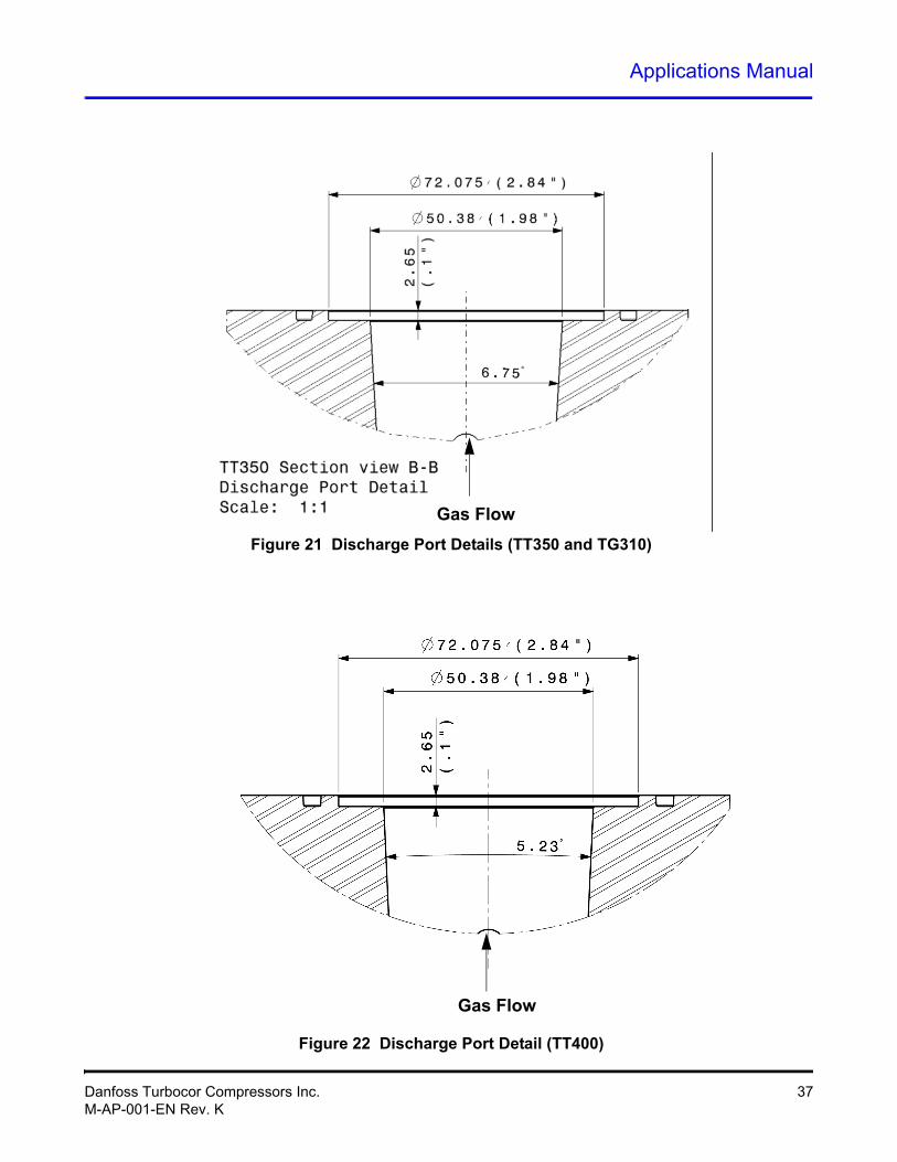
Gas Flow
Figure 21 Discharge Port Details (TT350 and TG310)
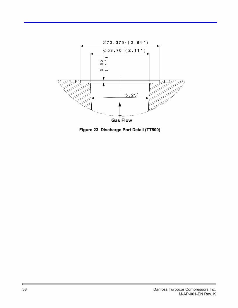
Gas Flow
Figure 22 Discharge Port Detail (TT400)
Danfoss Turbocor Compressors Inc. 37M-AP-001-EN Rev. K
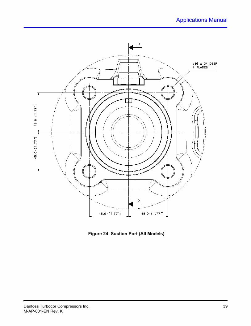
Gas Flow
Figure 23 Discharge Port Detail (TT500)
38 Danfoss Turbocor Compressors Inc.M-AP-001-EN Rev. K
Applications Manual
Figure 24 Suction Port (All Models)
Danfoss Turbocor Compressors Inc. 39M-AP-001-EN Rev. K
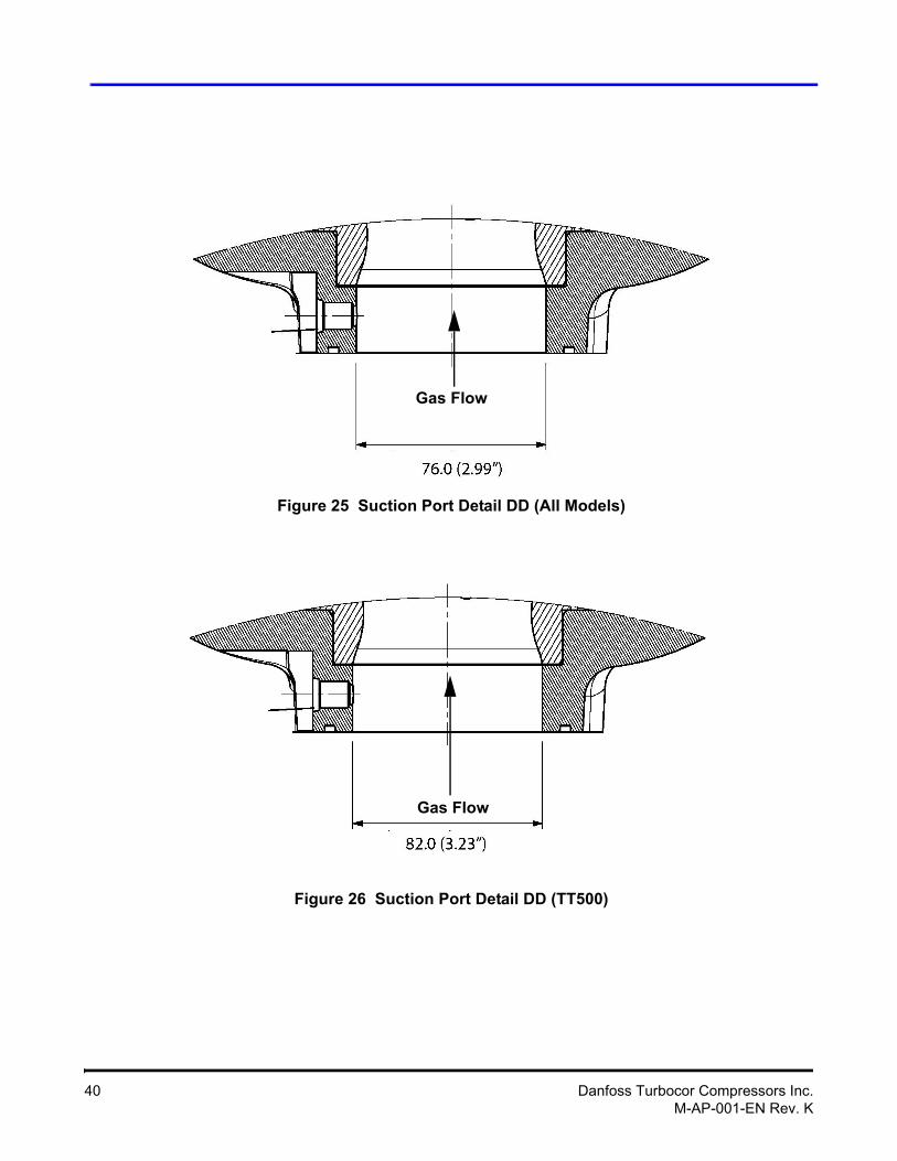
Figure 25 Suction Port Detail DD (All Models)
Figure 26 Suction Port Detail DD (TT500)
Gas Flow
Gas Flow
40 Danfoss Turbocor Compressors Inc.M-AP-001-EN Rev. K
Applications Manual
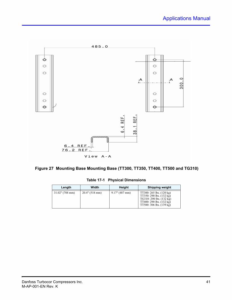
Figure 27 Mounting Base Mounting Base (TT300, TT350, TT400, TT500 and TG310)
Table 17-1 Physical Dimensions
Length Width Height Shipping weight
31.02" (788 mm) 20.4" (518 mm) 9.17" (487 mm) TT300: 265 lbs. (120 kg)TT350: 290 lbs. (132 kg)TG310: 290 lbs. (132 kg)TT400: 290 lbs. (132 kg)TT500: 306 lbs. (139 kg)
Danfoss Turbocor Compressors Inc. 41M-AP-001-EN Rev. K
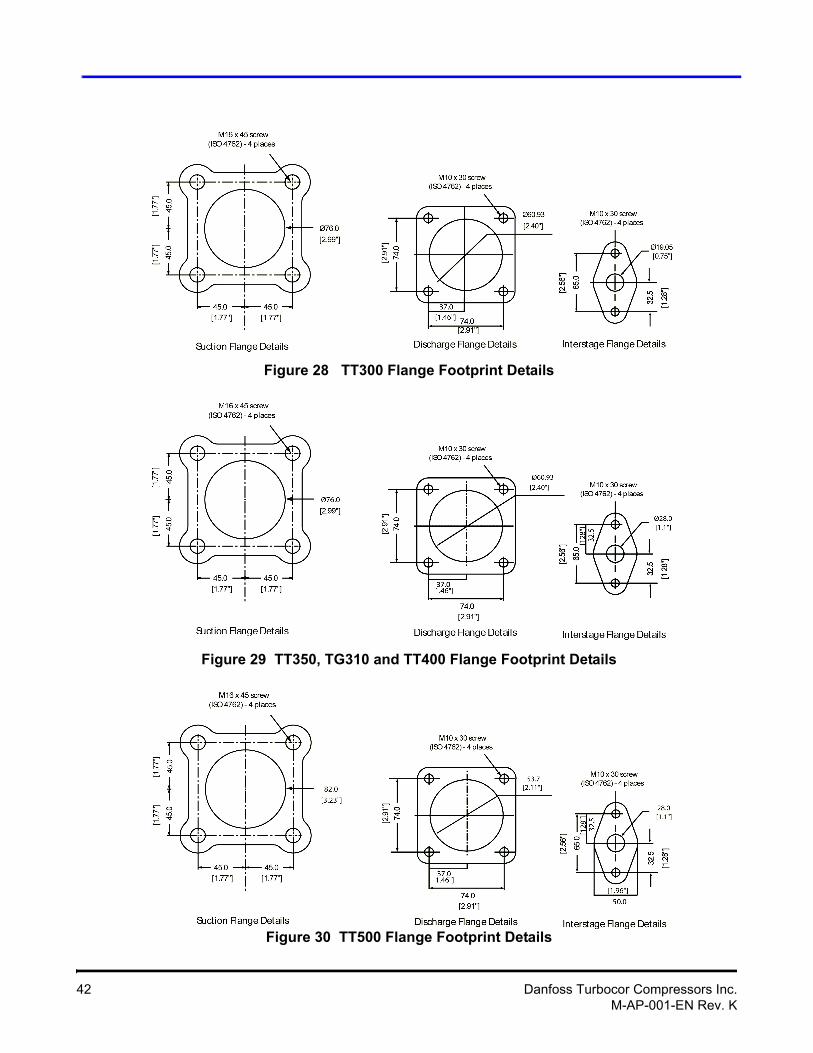
Figure 28 TT300 Flange Footprint Details
Figure 29 TT350, TG310 and TT400 Flange Footprint Details
Figure 30 TT500 Flange Footprint Details
42 Danfoss Turbocor Compressors Inc.M-AP-001-EN Rev. K
Applications Manual
18 Guide SpecificationsThis section contains written specifications for the TT300/TT350/TT400/TT500/TG310 compressors for use in system design specifications.
18.1 General
Construction shall utilize a two-stage, variable-speed, centrifugal compressor design requiring no oil for lubrication. Compressor shall be constructed with cast aluminum casing and high-strength thermoplastic electronics enclosures. The two-stage centrifugal impellers shall consist of cast and machined aluminum. The motor rotor and impeller assembly shall be the only major moving parts.
18.2 Refrigerant
Compressors shall be designed for use with R134a with the exception of the TG310 which is designed for use with R1234ze(E).
18.3 Compressor Bearings
The compressor shall be provided with radial and axial magnetic bearings to levitate the shaft, thereby eliminating metal-to-metal contact, and thus eliminating friction and the need for oil. The magnetic bearing system shall consist of front, rear, and axial bearings. Both the front and the rear bearings are to levitate the shaft at X and Y directions, and the axial at Z direction. Each bearing position shall be sensed by position sensors to provide real-time repositioning of the rotor shaft, controlled by onboard digital electronics.
18.4 Capacity Control
The compressor shall have a Variable Frequency Drive (VFD) for linear capacity modulation, high part-load efficiency and reduced in-rush starting current. It shall include an Insulated Gate Bipolar Transistor (IGBT) type inverter that converts the DC voltage to an adjustable three-phase AC voltage. Signals from the compressor controller shall determine the inverter output frequency, voltage and phase, thereby regulating the motor speed. In case of power failure, the compressor shall be capable of allowing for a normal de-levitation and shutdown.
Compressor speed shall be reduced as condensing temperature and/or heat load reduces, optimizing energy performance through the entire range from 100 percent to 30 percent or below. Capacity modulates infinitely as motor speed is varied across the range. Inlet Guide Vanes (IGVs) shall be built-in to further trim the compressor capacity in conjunction with the variable-speed control to optimize compressor performance at low loads. Refer to DTC Selection Software for performance calculations and limits.
18.5 Compressor Motor
The compressor shall be provided with a direct-drive, high-efficiency, permanent-magnet synchronous motor powered by pulse-width-modulating (PWM) voltage supply. The motor shall be compatible with high-speed variable-frequency operation that affords high-speed efficiency, compactness and soft start capability. Motor cooling shall be by liquid refrigerant injection.
18.6 Compressor Electronics
The compressor shall include a microprocessor controller capable of controlling magnetic bearings and speed control. The controller shall be capable of providing monitoring, including commissioning assistance, energy outputs, operation trends, and fault codes via a ModBus interface.
Danfoss Turbocor Compressors Inc. 43M-AP-001-EN Rev. K
18.6.1 Ancillary Devices
A check valve shall be installed on the discharge port of the compressor to protect against backflow of refrigerant during coast down. It is recommended that the valve be located after the properly designed discharge cone adaptor, preferably close to the condenser in the packaged system. The system shall also be provided with an appropriately sized line reactor.
44 Danfoss Turbocor Compressors Inc.M-AP-001-EN Rev. K
Applications Manual
19 System Design Guidelines In addition to the instructions detailed in the TT300, TT350, TT40, TT500 and TG310 technical documentation set, this section provides basic guidelines and requirements for the design and manufacture of R134a systems equipped with DTC compressors.
Refer to the applicable DTC technical manual for applications, operating, installation and commissioning instructions.
19.1 General Requirements
1. Check for compliance with all installation, operating, commissioning and service steps, as outlined in the documentation set. Check for the appropriate operating envelope and minimum unloading capacity for the intended application.
2. System components such as evaporators, condensers, valves, etc., should be properly selected and sized for appropriate performance and compatibility to suit R134a refrigerant. Compatibility to suit R1234ze(E) refrigerant is required for TG310.
3. The system suction and discharge piping should be properly designed and selected for minimum pressure drop. This requirement is more critical with the suction line. Since the Turbocor compressor operates without lubricating oil, conventional piping considerations that ensure oil return, such as multiple risers and traps, are not required. In all cases of suction and discharge lines, a bigger diameter is better.
4. For improved efficiency and better control, particularly at low load / low compression ratios, electronic expansion valves (EXVs) are strongly recommended. To take advantage of low pressure ratio operation to improve low load performance and efficiency, EXV capacity should be selected accordingly. Thermal expansion valves (TXVs) are not recommended due to the general inability of these devices to adequately cover the operating spectrum of centrifugal compressors, particularly at low compression ratios.
5. Take all necessary precautions to prevent any possibility of liquid floodback to the compressor. This means consideration during the ON and OFF cycles, particularly in multiple compressor installations. This WILL include, but is not limited to, the inclusion of a liquid line solenoid valve and piping, evaporator and condenser arranged in a manner that prevents free drainage of liquid to compressor.
6. The refrigeration piping system must be clean and free of all debris in accordance with refrigeration-industry best practices Particles can damage the compressor.
7. Each compressor MUST be fitted with its own positive sealing discharge line check valve. This valve MUST be selected as a minimum pressure drop at full capacity and low 'crack open' pressure. A robust, good quality valve must be selected to ensure good performance as valves may 'hammer' during start up, particularly in air cooled and/or multiple compressor systems. It is recommended that the valve be located after the properly designed discharge cone adaptor, preferably close to the condenser in the packaged system.
8. For outdoor installations, a weather-proof enclosure with vents is recommended to house the compressor.
NOTEThe compressor internal safety control settings are designed to provide protection for the compressor only. Designers MUST provide SYSTEM protection within their control design. DTC will not be responsible for system protection other than the compressor.
Danfoss Turbocor Compressors Inc. 45M-AP-001-EN Rev. K
9. Installation of staging valves are recommended on each compressor discharge line in the multiple compressor systems to aid the lag compressor startup.
10. It is recommended that a Load Balancing Valve (LBV) be installed to aid unloaded operation and lag compressor start-up in multiple-compressor systems.
11. The system control should not be designed based on pump down cycle. The system cannot be pumped down due to the surge characteristics of centrifugal compressors.
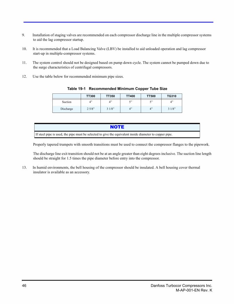
12. Use the table below for recommended minimum pipe sizes.
Properly tapered trumpets with smooth transitions must be used to connect the compressor flanges to the pipework.
The discharge line exit transition should not be at an angle greater than eight degrees inclusive. The suction line length should be straight for 1.5 times the pipe diameter before entry into the compressor.
13. In humid environments, the bell housing of the compressor should be insulated. A bell housing cover thermal insulator is available as an accessory.
Table 19-1 Recommended Minimum Copper Tube Size
TT300 TT350 TT400 TT500 TG310
Suction 4” 4” 5” 5” 4”
Discharge 2 5/8” 3 1/8” 4” 4” 3 1/8”
NOTEIf steel pipe is used, the pipe must be selected to give the equivalent inside diameter to copper pipe.
46 Danfoss Turbocor Compressors Inc.M-AP-001-EN Rev. K
Applications Manual
19.2 Economizer Option
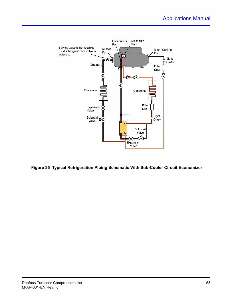
Turbocor compressors use two stage centrifugal compression with interstage port availability. This feature provides advantages of capacity and efficiency improvement when an economizer is installed. The improvements in efficiency and capacity are a result of further sub-cooling of the liquid refrigerant. Two types of economizer arrangements can be used: sub-cooler or flash tank. See Figure 34 and Figure 35. Refrigerant must enter the compressor through the economizer port in a “gas” state. Care must be taken to ensure that no liquid enters the compressor.
To determine compressor capacity and efficiency, the economizer performance rating option is available in the Selection Software on the Customer Service and Support - Performance Tools section of the DTC web page (www.turbocor.com). The circuit must be properly designed to reflect the specified heat exchanger approach with minimized pressure drops across the liquid side and expansion side. Piping design, including expansion device selection and pipe sizing, should be in accordance with best practices.
NOTE
19.3 Motor/Electronics Cooling Requirements
To ensure sub-cooled liquid, it is important that the condenser is fitted with a sub-cooler (integrated or separate).
It is essential that compressor motor and power electronics cooling is available immediately at start up. The compressor motor cooling liquid feed line must be configured and located so that this occurs. Recommended minimum pipe size is 1/2” for all models. A larger size may be necessary in some situations such as systems with low subcooling on start or extended piping runs. A full flow filter / drier must be installed and a liquid sight glass must be installed adjacent to each compressor.
19.4 Electrical Requirements
1. Power is permanently connected to the compressor connection terminals. A line reactor must be connected in series with the compressor connection. The line reactor enclosure or box should be properly ventilated to avoid overheating.
2. DTC recommends the use of a properly selected surge suppressor on the power supply to the compressor in installations susceptible to lightning (refer to Figure 11).
3. Fast Acting fuses with an appropriate CAT and current rating must be supplied and fitted externally for the TT350, TG310, TT400, and TT500. Fuses should be sized for 1.25 times compressor FLA. Fuses are fitted standard with the TT300.
4. 3 phase power wiring between the compressor and the line reactor must be either a fully shielded and sheathed type or carried in a properly grounded metal conduit.
NOTES• Sub-cooled liquid must be fed to the motor/electronics cooling port of the compressor.
• It must be solid liquid with a minimum of 6° F (3.5°C) sub cooled at the connection point to the motor/electronics cooling port of the compressor.
Filter dryer, sight glass and service valve must be fitted in the motor-cooling liquid line.
Danfoss Turbocor Compressors Inc. 47M-AP-001-EN Rev. K
19.5 Application-Specific Requirements
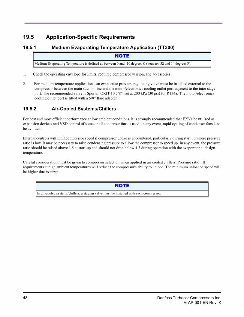
19.5.1 Medium Evaporating Temperature Application (TT300)
1. Check the operating envelope for limits, required compressor version, and accessories.
2. For medium-temperature applications, an evaporator pressure regulating valve must be installed external to the compressor between the main suction line and the motor/electronics cooling outlet port adjacent to the inter stage port. The recommended valve is Sporlan ORIT-10 7/8”, set at 200 kPa (30 psi) for R134a. The motor/electronics cooling outlet port is fitted with a 5/8” flare adapter.
19.5.2 Air-Cooled Systems/Chillers
For best and most efficient performance at low ambient conditions, it is strongly recommended that EXVs be utilized as expansion devices and VSD control of some or all condenser fans is used. In any event, rapid cycling of condenser fans is to be avoided.
Internal controls will limit compressor speed if compressor choke is encountered, particularly during start up where pressure ratio is low. It may be necessary to raise condensing pressure to allow the compressor to speed up. In any event, the pressure ratio should be raised above 1.5 at start-up and should not drop below 1.3 during operation with the evaporator at design temperature.
Careful consideration must be given to compressor selection when applied in air cooled chillers. Pressure ratio lift requirements at high ambient temperatures will reduce the compressor's ability to unload. The minimum unloaded speed will be higher due to surge.
NOTEMedium Evaporating Temperature is defined as between 0 and -10 degrees C (between 32 and 14 degrees F).
NOTEIn air-cooled systems/chillers, a staging valve must be installed with each compressor.
48 Danfoss Turbocor Compressors Inc.M-AP-001-EN Rev. K
Applications Manual
19.5.3 Inverted Start
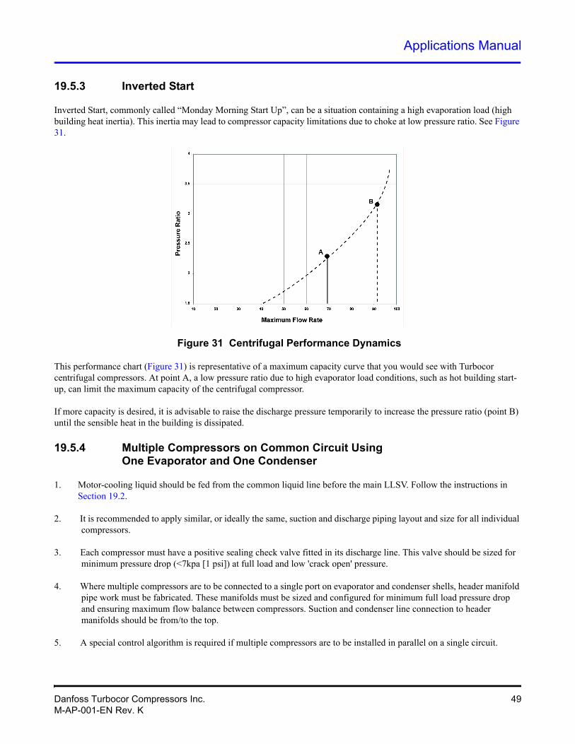
Inverted Start, commonly called “Monday Morning Start Up”, can be a situation containing a high evaporation load (high building heat inertia). This inertia may lead to compressor capacity limitations due to choke at low pressure ratio. See Figure 31.
Figure 31 Centrifugal Performance Dynamics
This performance chart (Figure 31) is representative of a maximum capacity curve that you would see with Turbocor centrifugal compressors. At point A, a low pressure ratio due to high evaporator load conditions, such as hot building start-up, can limit the maximum capacity of the centrifugal compressor.
If more capacity is desired, it is advisable to raise the discharge pressure temporarily to increase the pressure ratio (point B) until the sensible heat in the building is dissipated.
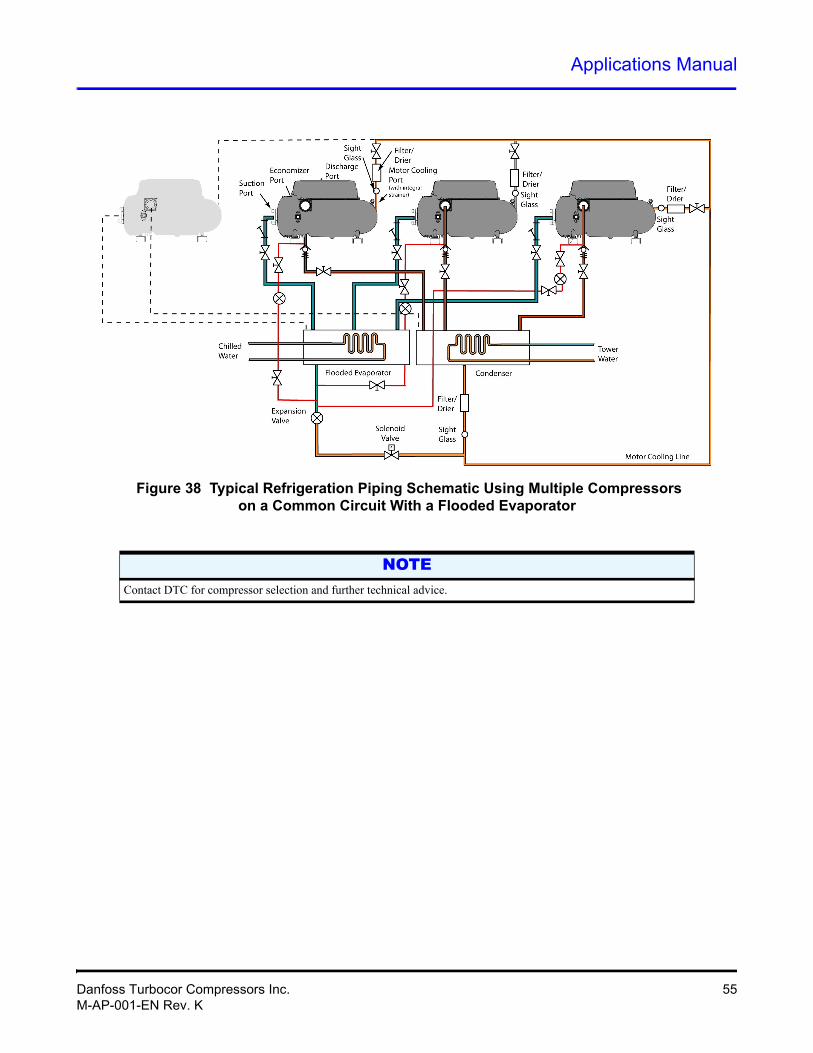
19.5.4 Multiple Compressors on Common Circuit UsingOne Evaporator and One Condenser
1. Motor-cooling liquid should be fed from the common liquid line before the main LLSV. Follow the instructions in Section 19.2.
2. It is recommended to apply similar, or ideally the same, suction and discharge piping layout and size for all individual compressors.
3. Each compressor must have a positive sealing check valve fitted in its discharge line. This valve should be sized for minimum pressure drop (<7kpa [1 psi]) at full load and low 'crack open' pressure.
4. Where multiple compressors are to be connected to a single port on evaporator and condenser shells, header manifold pipe work must be fabricated. These manifolds must be sized and configured for minimum full load pressure drop and ensuring maximum flow balance between compressors. Suction and condenser line connection to header manifolds should be from/to the top.
5. A special control algorithm is required if multiple compressors are to be installed in parallel on a single circuit.
Danfoss Turbocor Compressors Inc. 49M-AP-001-EN Rev. K
6. During the compressor staging process, to get the lag compressor online, the system pressure ratio should be below a maximum level of 2.4.
7. Staging valves are required for staging lag compressors. The take-off point from the discharge line should be upstream of the non-return valve.
8. The maximum start-up pressure ratio is about 2.4. If the pressure ratio is higher than 2.4, an LBV is required to reduce the pressure ratio before starting the compressor.
NOTE
19.5.5 Packaged Air-Side With DX-Type Evaporator and Multiple Evaporator Coils
1. Each evaporator must be controlled by an independent EXV, using its outlet header for superheat control reference. Common suction temperature or pressure should not be used for individual evaporator superheat control reference points,
2. Each evaporator liquid line should be equipped with a solenoid valve.
3. Connection of a generously-sized header to the suction line of the evaporators is recommended to minimize pressure-drop differences.
4. It is recommended to install a suction line accumulator.
5. Motor-cooling liquid should be fed from the common liquid line Follow the instructions in Section 19.2.
Contact Danfoss Turbocor for compressor selection and technical advice.
50 Danfoss Turbocor Compressors Inc.M-AP-001-EN Rev. K
Applications Manual
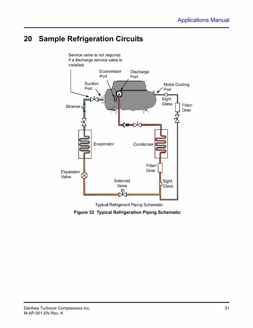
20 Sample Refrigeration Circuits
Figure 32 Typical Refrigeration Piping Schematic
Danfoss Turbocor Compressors Inc. 51M-AP-001-EN Rev. K
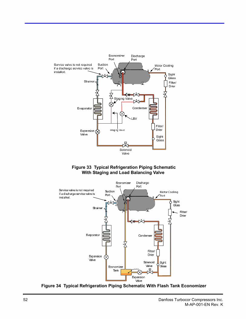
Figure 33 Typical Refrigeration Piping SchematicWith Staging and Load Balancing Valve
Figure 34 Typical Refrigeration Piping Schematic With Flash Tank Economizer
52 Danfoss Turbocor Compressors Inc.M-AP-001-EN Rev. K
Applications Manual
Figure 35 Typical Refrigeration Piping Schematic With Sub-Cooler Circuit Economizer
Danfoss Turbocor Compressors Inc. 53M-AP-001-EN Rev. K
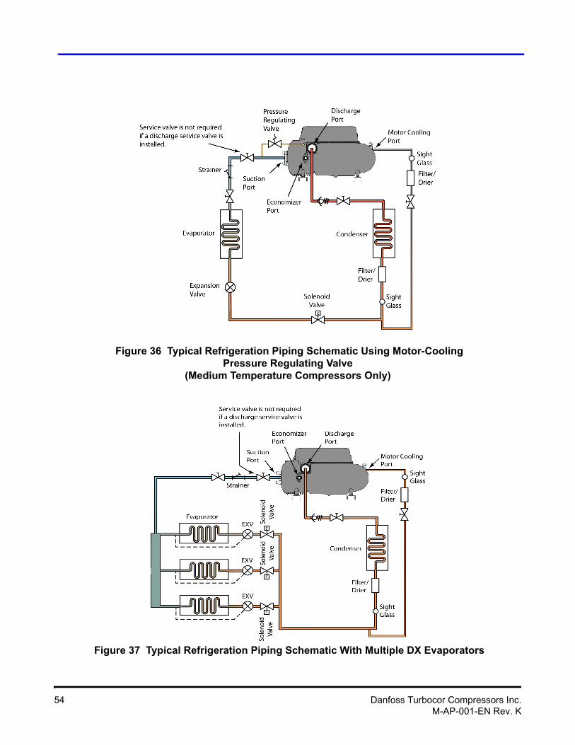
Figure 36 Typical Refrigeration Piping Schematic Using Motor-Cooling Pressure Regulating Valve
(Medium Temperature Compressors Only)
Figure 37 Typical Refrigeration Piping Schematic With Multiple DX Evaporators
54 Danfoss Turbocor Compressors Inc.M-AP-001-EN Rev. K
Applications Manual
Figure 38 Typical Refrigeration Piping Schematic Using Multiple Compressorson a Common Circuit With a Flooded Evaporator
NOTEContact DTC for compressor selection and further technical advice.
Danfoss Turbocor Compressors Inc. 55M-AP-001-EN Rev. K
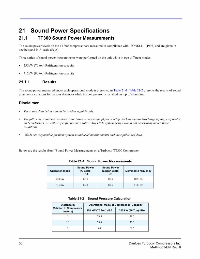
21 Sound Power Specifications21.1 TT300 Sound Power Measurements
The sound power levels on the TT300 compressor are measured in compliance with ISO 9614-1 (1993) and are given in decibels and in A-scale dB(A).
Three series of sound power measurements were performed on the unit while in two different modes:
• 250kW (70 ton) Refrigeration capacity
• 315kW (90 ton) Refrigeration capacity
21.1.1 Results
The sound power measured under each operational mode is presented in Table 21-1. Table 21-2 presents the results of sound pressure calculations for various distances while the compressor is installed on top of a building
Disclaimer
• The sound data below should be used as a guide only.
• The following sound measurements are based on a specific physical setup, such as suction/discharge piping, evaporator and condensers, as well as specific pressure ratios. Any OEM system design would not necessarily match these conditions.
• OEMs are responsible for their system sound level measurements and their published data.
Below are the results from “Sound Power Measurements on a Turbocor TT300 Compressor.
Table 21-1 Sound Power Measurements
Operation ModeSound Power
(A-Scale) dBA
Sound Power(Linear Scale)
dBDominant Frequency
250 kW 81.5 81.5 1070 Hz
315 kW 86.0 85.5 1180 Hz
Table 21-2 Sound Pressure Calculation
Distance inRelation to Compressor
(meters)
Operational Mode of Compressor (Capacity)
250 kW (70 Ton) dBA 315 kW (90 Ton) dBA
1 73.5 78.0
1.5 70.0 70.0
3 64 68.5
56 Danfoss Turbocor Compressors Inc.M-AP-001-EN Rev. K
Applications Manual
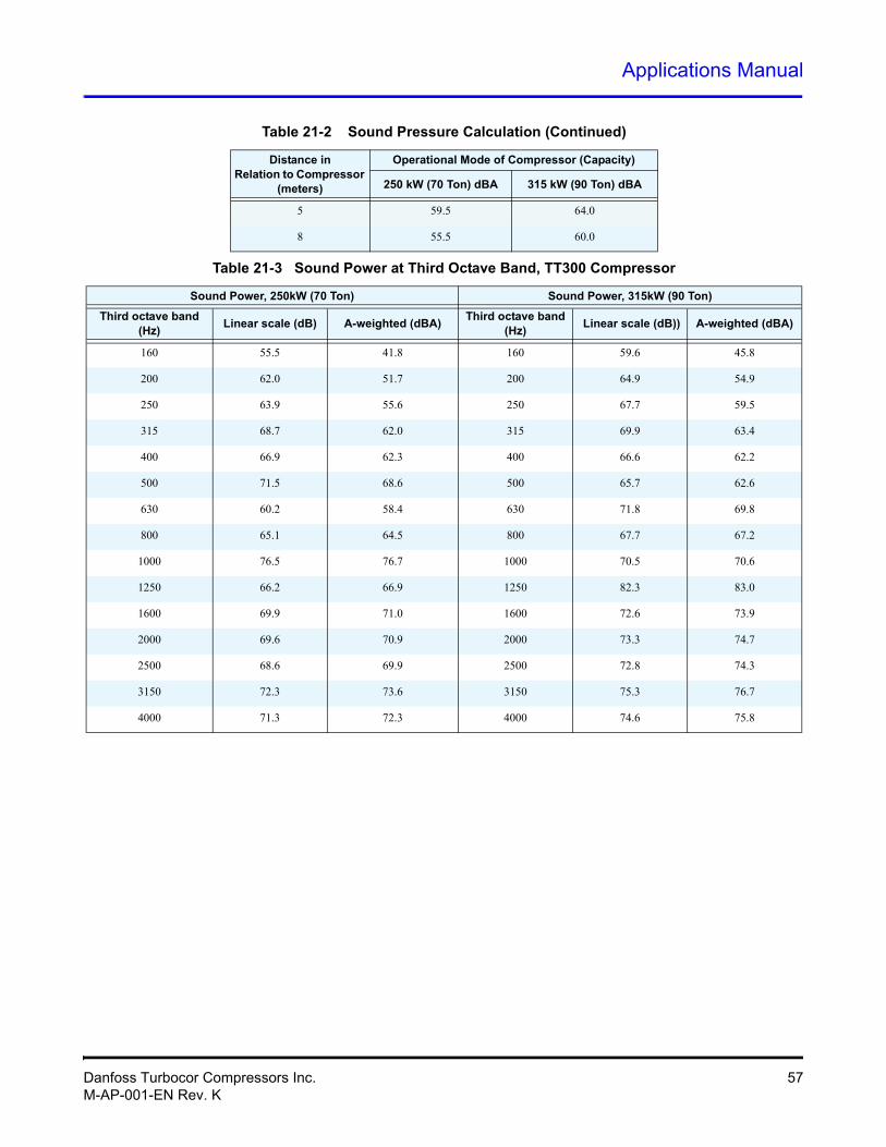
5 59.5 64.0
8 55.5 60.0
Table 21-3 Sound Power at Third Octave Band, TT300 Compressor
Sound Power, 250kW (70 Ton) Sound Power, 315kW (90 Ton)
Third octave band (Hz)
Linear scale (dB) A-weighted (dBA) Third octave band
(Hz) Linear scale (dB)) A-weighted (dBA)
160 55.5 41.8 160 59.6 45.8
200 62.0 51.7 200 64.9 54.9
250 63.9 55.6 250 67.7 59.5
315 68.7 62.0 315 69.9 63.4
400 66.9 62.3 400 66.6 62.2
500 71.5 68.6 500 65.7 62.6
630 60.2 58.4 630 71.8 69.8
800 65.1 64.5 800 67.7 67.2
1000 76.5 76.7 1000 70.5 70.6
1250 66.2 66.9 1250 82.3 83.0
1600 69.9 71.0 1600 72.6 73.9
2000 69.6 70.9 2000 73.3 74.7
2500 68.6 69.9 2500 72.8 74.3
3150 72.3 73.6 3150 75.3 76.7
4000 71.3 72.3 4000 74.6 75.8
Table 21-2 Sound Pressure Calculation (Continued)
Distance inRelation to Compressor
(meters)
Operational Mode of Compressor (Capacity)
250 kW (70 Ton) dBA 315 kW (90 Ton) dBA
Danfoss Turbocor Compressors Inc. 57M-AP-001-EN Rev. K
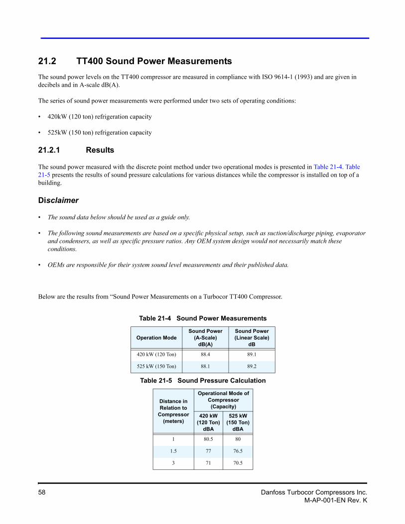
21.2 TT400 Sound Power Measurements
The sound power levels on the TT400 compressor are measured in compliance with ISO 9614-1 (1993) and are given in decibels and in A-scale dB(A).
The series of sound power measurements were performed under two sets of operating conditions:
• 420kW (120 ton) refrigeration capacity
• 525kW (150 ton) refrigeration capacity
21.2.1 Results
The sound power measured with the discrete point method under two operational modes is presented in Table 21-4. Table 21-5 presents the results of sound pressure calculations for various distances while the compressor is installed on top of a building.
Disclaimer
• The sound data below should be used as a guide only.
• The following sound measurements are based on a specific physical setup, such as suction/discharge piping, evaporator and condensers, as well as specific pressure ratios. Any OEM system design would not necessarily match these conditions.
• OEMs are responsible for their system sound level measurements and their published data.
Below are the results from “Sound Power Measurements on a Turbocor TT400 Compressor.
Table 21-4 Sound Power Measurements
Operation ModeSound Power
(A-Scale)dB(A)
Sound Power (Linear Scale)
dB
420 kW (120 Ton) 88.4 89.1
525 kW (150 Ton) 88.1 89.2
Table 21-5 Sound Pressure Calculation
Distance in Relation to
Compressor (meters)
Operational Mode of Compressor (Capacity)
420 kW (120 Ton)
dBA
525 kW (150 Ton)
dBA
1 80.5 80
1.5 77 76.5
3 71 70.5
58 Danfoss Turbocor Compressors Inc.M-AP-001-EN Rev. K
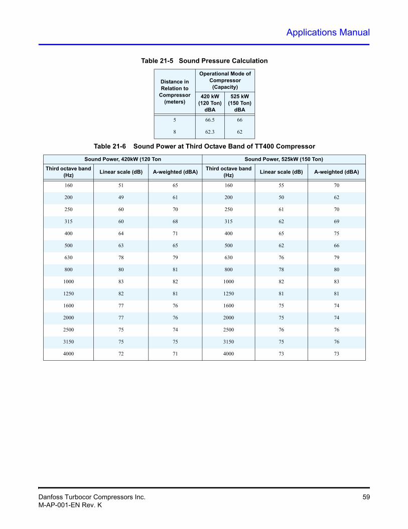
Applications Manual
5 66.5 66
8 62.3 62
Table 21-6 Sound Power at Third Octave Band of TT400 Compressor
Sound Power, 420kW (120 Ton Sound Power, 525kW (150 Ton)
Third octave band (Hz)
Linear scale (dB) A-weighted (dBA)Third octave band
(Hz) Linear scale (dB) A-weighted (dBA)
160 51 65 160 55 70
200 49 61 200 50 62
250 60 70 250 61 70
315 60 68 315 62 69
400 64 71 400 65 75
500 63 65 500 62 66
630 78 79 630 76 79
800 80 81 800 78 80
1000 83 82 1000 82 83
1250 82 81 1250 81 81
1600 77 76 1600 75 74
2000 77 76 2000 75 74
2500 75 74 2500 76 76
3150 75 75 3150 75 76
4000 72 71 4000 73 73
Table 21-5 Sound Pressure Calculation
Distance in Relation to
Compressor (meters)
Operational Mode of Compressor (Capacity)
420 kW (120 Ton)
dBA
525 kW (150 Ton)
dBA
Danfoss Turbocor Compressors Inc. 59M-AP-001-EN Rev. K

60 Danfoss Turbocor Compressors Inc.M-AP-001-EN Rev. K
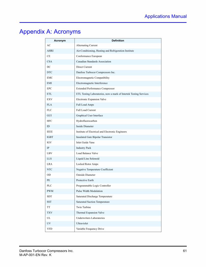
Applications Manual
Appendix A: AcronymsAcronym Definition
AC Alternating Current
AHRI Air-Conditioning, Heating and Refrigeration Institute
CE Conformance European
CSA Canadian Standards Association
DC Direct Current
DTC Danfoss Turbocor Compressors Inc.
EMC Electromagnetic Compatibility
EMI Electromagnetic Interference
EPC Extended Performance Compressor
ETL ETL Testing Laboratories, now a mark of Intertek Testing Services
EXV Electronic Expansion Valve
FLA Full Load Amps
FLC Full Load Current
GUI Graphical User Interface
HFC Hydrofluorocarbon
ID Inside Diameter
IEEE Institute of Electrical and Electronic Engineers
IGBT Insulated Gate Bipolar Transistor
IGV Inlet Guide Vane
IP Industry Pack
LBV Load Balance Valve
LLS Liquid Line Solenoid
LRA Locked Rotor Amps
NTC Negative Temperature Coefficient
OD Outside Diameter
PE Protective Earth
PLC Programmable Logic Controller
PWM Pulse Width Modulation
SDT Saturated Discharge Temperature
SST Saturated Suction Temperature
TT Twin Turbine
TXV Thermal Expansion Valve
UL Underwriters Laboratories
UV Ultraviolet
VFD Variable Frequency Drive
Danfoss Turbocor Compressors Inc. 61M-AP-001-EN Rev. K

THIS PAGE INTENTIONALLY LEFT BLANK.
62 Danfoss Turbocor Compressors Inc.M-AP-001-EN Rev. K
Applications Manual
AAC 61
voltage range 23accessories 11acronyms 61AHRI 61air-cooled units 48ancillary devices 44application
temperature 48Bbase
mounting 34bearings 43Ccable
AC input - see specification, cableinterface 30
capacity control 43CE 61
compliance 25CE Certification
TG310 7TT300 7TT350 7TT400 7
CE Certification TT500 7CE compliance 25certification 7clearance 34compliance
CE 25compressor
bearings 43discharge side view 35electronics 43I/O board mounting 31motor 43multiple on common circuit 49service side view 35
compressor bearings 43considerations
environmental 33piping 32shipping 33
construction 9contactor
power line 25control
capacity 43parallel 22staged 22
Control Interface Wiring 28control logic
multiple compressors 22control logic guidelines
multiple compressors 22parallel control 22staged control 22
control wiring 28connection guidelines 29details 29typical 28
CSA 61Ddata
physical 34DC 61design guidelines 45
application-specific requirements 48electrical requirements 47general requirements 45
dimensionsflanges 42, 43mounting base 36
Discharge Port DetailTT300 36TT400 37TT500 38
discharge sideview 35
Discharge Side ViewTG310 35TT300 35TT350 35TT400 35TT500 35
disconnects 23DTC 61
Danfoss Turbocor Compressors Inc. 63M-AP-001-EN Rev. K
Eelectrical
requirements 47electrical connections
typical 24electrical specifications 23
disconnects 23electronics 43EMC 61EMI 61EMI/EMC filtering 25environment 10environmental considerations 33EPC 61equipment panel 27ETL 61ETL certification
TG310 7TT300 7TT350
ETL certificationTT400 7
TT500 7evaporator
requirements 50EXV 61Ffilter
EMI/EMC 25harmonic 25
filteringEMI/EMC 25harmonic 25
FLA 61Flange Details
TT400 42flange details
TG310 42TT300 42TT350 42TT400 42TT500 42
flangesvalve 36
FLC 61
frequency range 23Ggeneral specifications 8grounding
connection guidelines 26Earth connection guidelines 26
grounding connectionstypical 26
GUI 61guidelines
control wiring 29control wiring connections 29grounding
connection 26system design 45
Hharmonic filtering 25HFC 61humidity 33II/O board
mounting details 31ID 61IEEE 61IGBT 61IGV 61interface cable 30IP 61LLBV 61line protection 24LLS 61LRA 61MMains Input Cable
specification 27Maximum Pressure
TG310 8TT300 8TT350 8TT400 8TT500 8
maximum pressure 8measurements
sound power 58
64 Danfoss Turbocor Compressors Inc.M-AP-001-EN Rev. K
Applications Manual
sound power (TT300) 56Minimum Unloading Capacity
TG310 21TT300 19TT350 20TT400 20TT500 21
motorcompressor 43cooling line 32
Mounting BaseTG310 41TT300 41TT350, Mounting Base
TT400 41TT500 41
mounting base 34dimensions 36
mounting detailsI/O board 31
multiple compressorscommon circuit 49control logic 22
Nnoise 10NTC 61OOD 61Operating Envelope
TG310 16TT300 15TT350 16TT400 17TT500 18
operating range 14extended performance compressor 14medium temperature compressor 15
Ppanel
equipment 27parallel control 22PE 61physical data 34piping
considerations 32
piping considerations 32PLC 61power line
contactor 25pressure
maximum 8protection
surge 25PWM 61Rrange
AC voltage 23frequency 23operating 14
refrigerant 43TG310 43type 10
refrigerant type 10refrigeration
sample circuits 51typical piping schematic 54, 55
Refrigeration Pipingschematic using motor-cooling pressure regu-
lating valve 54schematic using multiple compressors on a
common circuit 55schematic with flash tank economizer 52schematic with load balancing valve 52schematic with multiple DX evaporators 54schematic with sub-cooler circuit economizer
53typical schematic 51
requirementsapplication-specific 48electrical 47evaporator 50general 45
Ssafety summary 7SDT 61Service Side View
TG310 35TT300 35TT350 35TT400 35
Danfoss Turbocor Compressors Inc. 65M-AP-001-EN Rev. K
TT500 35shipping considerations 33sound 56sound power
measurements 56TT40) 58
sound pressurecalculation 56
sound pressure calculation 58specification
accessories 56cable 27supply voltage 23
specificationsancillary devices 44capacity control 43compressor bearings 43compressor electronics 43compressor motor 43electrical 23general 8refrigerant 43TG310 43TT300 43TT350 43TT400 43TT500 43
SST 61staged control 22Suction Front View
TG310 34TT300 34TT350 34TT400 34TT500 34
Suction PortT300 39TG310 39TT350 39TT400 39TT500 39
Suction Port DetailTG310 39TT300 39TT350 39
TT400, 39TT500 39
supply voltagespecification 23
surge protection 25system design
general requirements 45guidelines 45
Ttemperature
application 48TG310
flange details 42minimum unloading capacity 21operating envelope 16
TT 61TT300
minimum unloading capacity 19operating envelope 15sound power measurements 56valve flange details 42
TT350mnimum unloading capacity 20operating envelope 16valve flange details 42
TT400minimum unloading capacity 20operating envelope 17sound power measurements 58valve flange details 42
TT500flange valve details 42minimum unloading capacity 21operating envelope 18
TXV 61UUL 61units
air-cooled 48unloading capacity
minimum 19UV 61Vvalve
flanges 36
66 Danfoss Turbocor Compressors Inc.M-AP-001-EN Rev. K
Applications Manual
valve flangedetails TT300 42
valve flange details TT400 42VFD 61vibration 33view
discharge side 35
voltage rangeAC 23
Wwiring
control 28control interface 28
Danfoss Turbocor Compressors Inc. 67M-AP-001-EN Rev. K

68 Danfoss Turbocor Compressors Inc.M-AP-001-EN Rev. K

This Page Left Intentionally Blank

Danfoss Turbocor Compressors Inc.M-AP-001-EN Rev. K
Danfoss Turbocor compressors Inc., 1769 East Paul Dirac Drive, Tallahassee, Florida 32310
Phone: 1-850-504-4800 Fax: 1-850-575-2126 www.turbocor.com