MODELS 2208e and 2204e TEMPERATURE CONTROLLERS
135
2208e and 2204e Controller Handbook Part No. HA026696 Issue 2.0 Sept -00 a-1 MODELS 2208e and 2204e TEMPERATURE CONTROLLERS INSTALLATION AND OPERATION HANDBOOK 1 Chapter 1 OPERATION Page 1.1 FRONT PANEL LAYOUT ............................................................ 1-2 1.2 GETTING STARTED ................................................................... 1-4 1.2.1 Viewing The Process Value and Setpoint ..........................................1-4 1.2.2 To Adjust The Setpoint .....................................................................1-4 1.2.3 Viewing The Display Units ................................................................1-5 1.2.4 Use Of The “SCROLL” Button ....................................................1-5 1.2.5 Use Of The ‘PAGE’ Button ..........................................................1-6 PARAMETER LISTS............................................................................. 1-7 1.4 manual or automatic control ..................................................... 1-8 1.4.1 Selecting Auto/Manual Operation .....................................................1-8 1.4.2 How To Manually Adjust Output Power.............................................1-9 1.5 SUMMARY................................................................................... 1-9 1.6 Selecting SETPOINT 1 OR SETPOINT 2 ................................. 1-10 1.7 RAMP DWELL FUNCTION........................................................ 1-11 1.7.1 To Set up a Ramp/Time Program................................................... 1-11 1.7.2 To Run the Program....................................................................... 1-12 1.7.3 Power Failure During Program Run ................................................ 1-12 1.8 Location of Parameters - Block Diagram ................................ 1-13 1.9 NAVIGATION DIAGRAM (Part A) .............................................. 1-14 NAViGATION Diagram (Part B) .......................................................... 1-15 1.10 parameter tables......................................................................... 1-16 1.10.2 Alarm List ................................................................................... 1-17 1.10.3 Autotune List .............................................................................. 1-17 1.10.4 PID List ...................................................................................... 1-18 1.10.5 Setpoint List ............................................................................... 1-19 1.10.6 Input List .................................................................................... 1-20 1.10.7 On/Off List .................................................................................. 1-20 1.10.8 Output List .................................................................................. 1-21 1.10.9 Communications List .................................................................. 1-21 1.10.10 Access List ................................................................................. 1-21 1.11 alarms .................................................................................... 1-22 1.11.1 Types of Alarm Used in the 2200 ................................................ 1-22 1.12 Alarm relay output................................................................. 1-23 1.12.1 SETTING ALARM LEVELS ......................................................... 1-24 1.12.2 ALARM INDICATION AND ACKNOWLEDGEMENT .................... 1-25
Transcript of MODELS 2208e and 2204e TEMPERATURE CONTROLLERS
2208e and 2204e Controller Handbook Part No. HA026696 Issue 2.0 Sept -00 a-1
MODELS 2208e and 2204eTEMPERATURE CONTROLLERS
INSTALLATION AND OPERATION HANDBOOK
1 Chapter 1 OPERATION Page1.1 FRONT PANEL LAYOUT ............................................................ 1-2
1.2 GETTING STARTED ................................................................... 1-41.2.1 Viewing The Process Value and Setpoint..........................................1-41.2.2 To Adjust The Setpoint .....................................................................1-41.2.3 Viewing The Display Units................................................................1-51.2.4 Use Of The “SCROLL” Button ....................................................1-51.2.5 Use Of The ‘PAGE’ Button ..........................................................1-6
PARAMETER LISTS............................................................................. 1-7
1.4 manual or automatic control ..................................................... 1-81.4.1 Selecting Auto/Manual Operation .....................................................1-81.4.2 How To Manually Adjust Output Power.............................................1-9
1.5 SUMMARY................................................................................... 1-9
1.6 Selecting SETPOINT 1 OR SETPOINT 2 ................................. 1-10
1.7 RAMP DWELL FUNCTION........................................................ 1-111.7.1 To Set up a Ramp/Time Program...................................................1-111.7.2 To Run the Program.......................................................................1-121.7.3 Power Failure During Program Run ................................................1-12
1.8 Location of Parameters - Block Diagram ................................ 1-13
1.9 NAVIGATION DIAGRAM (Part A) .............................................. 1-14
NAViGATION Diagram (Part B) .......................................................... 1-151.10 parameter tables.........................................................................1-161.10.2 Alarm List ...................................................................................1-171.10.3 Autotune List ..............................................................................1-171.10.4 PID List ......................................................................................1-181.10.5 Setpoint List ...............................................................................1-191.10.6 Input List ....................................................................................1-201.10.7 On/Off List..................................................................................1-201.10.8 Output List..................................................................................1-211.10.9 Communications List ..................................................................1-211.10.10 Access List .................................................................................1-21
1.11 alarms .................................................................................... 1-221.11.1 Types of Alarm Used in the 2200 ................................................1-22
1.12 Alarm relay output................................................................. 1-231.12.1 SETTING ALARM LEVELS.........................................................1-241.12.2 ALARM INDICATION AND ACKNOWLEDGEMENT....................1-25
a-2 2208e and 2204e Controller Handbook Part No. HA026696 Issue 2.0 Sept-00
1.12.3 DIAGNOSTIC ALARMS ............................................................. 1-26
2 Chapter 2 Installation 2-1
2.2 INSTRUMENT LAYOUTS............................................................ 2-22.2.2 Outline Dimensions Model 2208e .................................................... 2-32.2.3 Outline Dimensions Model 2204e .................................................... 2-3
2.3 Introduction................................................................................ 2-42.3.2 Controller labels .............................................................................. 2-4
2.4 MECHANICAL INSTALLATION .................................................. 2-42.4.2 Unplugging and plugging-in the controller ........................................ 2-4
2.5 wiring .......................................................................................... 2-52.5.2 Wire Sizes....................................................................................... 2-62.5.3 Wiring connections.......................................................................... 2-62.5.4 Sensor input connections ................................................................ 2-72.5.5 Outputs 1 and 2 connections ........................................................... 2-7
2.6 PDS modes ................................................................................. 2-8
2.7 Snubbers .................................................................................... 2-8
Typical single loop wiring diagram.................................................... 2-9
2.9 RS 232/485/422 Communication connections ........................ 2-102.9.2 Wiring of EIA-485 serial communication links................................ 2-11
2.10 Devicenet Wiring to Series 2200e Controllers ..................... 2-122.10.2 DeviceNet Terminal Functions.................................................... 2-122.10.3 Wiring Interconnections for DeviceNet Communications............. 2-13
3 Chapter 3 ACCESS LEVELS 3-1
3.2 THE DIFFERENT ACCESS LEVELS........................................... 3-2
3.3 SELECTING AN ACCESS LEVEL............................................... 3-33.3.2 Returning to Operator Level............................................................. 3-5
3.4 Edit level ..................................................................................... 3-53.4.2 Hiding or revealing a complete list ................................................... 3-63.4.3 Promoting a parameter.................................................................... 3-6
2208e and 2204e Controller Handbook Part No. HA026696 Issue 2.0 Sept -00 a-3
4. Chapter 4 TUNING .......................................................................... 4-1
4.1. WHAT IS TUNING? ..................................................................... 4-2
4.2. AUTOMATIC TUNING ................................................................. 4-34.2.1. Heating and Cooling Output Cycle Times .........................................4-3
4.3. How to Tune ............................................................................... 4-44.3.1. Typical automatic tuning cycle..........................................................4-54.3.2. Calculation of the cutback values .....................................................4-5
4.4. MANUAL TUNING ....................................................................... 4-64.4.1. Setting the cutback values................................................................4-74.4.2. Integrating action and manual reset..................................................4-84.4.3. Automatic droop compensation (Adc)...............................................4-8
5. Chapter 5 CONFIGURATION 5-1
5.1 SELECTING CONFIGURATION LEVEL 5-2
5.2 SELECTING A CONFIGURATION PARAMETER 5-3
5.3 LEAVING CONFIGURATION LEVEL 5-3
5.4 STEPS INVOLVED IN CONFIGURING A CONTROLLER 5-3
5.5 NAVIGATION DIAGRAM (PART A) 5-4
5.6NAVIGATION DIAGRAM (PART B) 5-5
5.7 CONFIGURATION PARAMETER TABLES 5-7
5.8 CONFIGURATION OF DIGITAL COMMUNICATIONS ………… 5-16
5.8.1. To Configure the Function and Baud Rate…………………………… 5-16 5.8.2. To Set Instrument Address…………………………………………… 5-17
5.9 DEVICENET…………………………………………………………… 5-17
5.9.1. The EDS File…………………………………………………………… 5-175.9.2. ODVA Compliance…………………………………………………… 5-17
6 Chapter 6 User calibration .............................................................. 6-1
6.8 What is the Purpose of User Calibration? ................................ 6-2
6.9 User Calibration Enable ............................................................. 6-3
6.10 Single point calibration .......................................................... 6-4
6.11 Two point calibration.............................................................. 6-5
6.12 Calibration points and Calibration offsets ............................ 6-6
a-4 2208e and 2204e Controller Handbook Part No. HA026696 Issue 2.0 Sept-00
7 Chapter 7 ALARM CONFIGURATION.............................................. 7-1
7.1 DEFINITION OF ALARMS AND EVENTS ................................... 7-27.1.1 TYPES OF ALARMS ....................................................................... 7-2
7.2 DIGITAL OUTPUT FUNCTIONS ................................................. 7-4
7.3 STEP1 - CONFIGURING THE FOUR ‘SOFT’ ALARMS.............. 7-5
7.4 STEP 2 - ATTACHING AN ALARM TO A PHYSICAL OUTPUT.. 7-6
7.5 STEP 3 - GROUPING ALARMS ON A SINGLE OUTPUT........... 7-7
7.6 STEP 4 - REMOVING ALARMS FROM AN OUTPUT ................. 7-7
8. Chapter 8 MOTORISED VALVE CONTROL .................................. 8-1
8.1. Parameters For Motorised Valve Control.................................. 8-2
8.2. Commissioning the Motorised Valve Controller ...................... 8-28.2.1. Adjusting the minimum on-time ‘Ont.H’ ........................................ 8-2
8.3. MOTORISED VALVE APPLICATIONS........................................ 8-38.3.1. Auto Tuning..................................................................................... 8-38.3.2. 2200e Valve Positioner Set-up Table ............................................... 8-3
9 Chapter 9 LOAD CURRENT MONITORING AND DIAGNOSTICS 9-1
9.1 Load Current Monitoring and Diagnostics ............................... 9-2
9.2 Example Wiring Diagram (For mode 1 & 2 operation).............. 9-3
Example Wiring Diagram (for mode 5 operation) ............................. 9-4
9.4 Operation.................................................................................... 9-5To Read Load Current (modes 2 and 5 only) ................................................ 9-59.1.2 To Display Load Current Continuously in the Lower Readout (modes 2
and 5 only)..................................................................................... 9-59.1.3 Display Modes ............................................................................... 9-59.1.4 How Heater Alarms Are Displayed.................................................. 9-6
9.5 To Set The Alarm Trip Levels .................................................... 9-7
9.6 relay outputs .............................................................................. 9-7
9.7 TO CONFIGURE PDS LOAD CURRENT DIAGNOSTICS ........... 9-89.1.5 To configure the Logic Module for PDS modes 1 or 2 ..................... 9-89.1.6 To configure logic input a for pds (Mode 5 only) ............................. 9-9
To Configure Low and High Current Trip Alarms........................... 9-10
2208e and 2204e Controller Handbook Part No. HA026696 Issue 2.0 Sept -00 a-5
9.9 To Attach Soft Alarms To A Relay Output .............................. 9-11
9.10 the scaling factor.................................................................. 9-129.1.7 To adjust the scaling factor .......................................................... 9-12
10 Chapter 10 RETRANSMISSION.................................................. 10-1
10.1 What is retransmission ........................................................ 10-2
10.2 To configure retransmission ............................................... 10-3
10.3 scaling retransmitted output signals .................................. 10-410.1.1 To Range Retransmitted Output OP ........................................ 10-410.1.2 To Range Retransmitted Setpoint SP or Process Variable PV 10-510.1.3 To Range Retransmitted Error Err ........................................ 10-5
Appendix A UNDERSTANDING THE ORDERING CODE ........ A-1
Appendix B SAFETY & EMC INFORMATION ....................... B-1
TECHNICAL SPECIFICATION ......................... B-6
This product is covered by one or more of the following US Patents:5,484,206 and 5,793,754; Additional patents pending.
PDSIO is a registered trademark of Eurotherm.
INSTANT ACCURACY™, SSRx Load Doctor™ and SSRx Enhanced Load Doctor ™are trademarks of Eurotherm.”
a-6 2208e and 2204e Controller Handbook Part No. HA026696 Issue 2.0 Sept-00
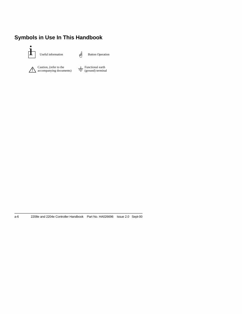
Symbols in Use In This Handbook
Useful information Button Operation
Caution, (refer to theaccompanying documents)
Functional earth(ground) terminal!
i G
Installation and Operation Handbook Operation
2208e and 2204e Controller 1-1
Chapter 1 OPERATION
1.1 FRONT PANEL LAYOUT................................................................... 2
1.2 GETTING STARTED.......................................................................... 41.2.1 Viewing The Process Value and Setpoint...............................................41.2.2 To Adjust The Setpoint ...........................................................................41.2.3 Viewing The Display Units ......................................................................51.2.4 Use Of The “SCROLL” Button ..........................................................51.2.5 Use Of The ‘PAGE’ Button ................................................................6
PARAMETER LISTS.................................................................................... 7
1.4 manual or automatic control ........................................................... 81.4.1 Selecting Auto/Manual Operation ...........................................................81.4.2 How To Manually Adjust Output Power...................................................9
1.5 SUMMARY ......................................................................................... 9
1.6 Selecting SETPOINT 1 OR SETPOINT 2 ....................................... 10
1.7 RAMP DWELL FUNCTION.............................................................. 111.7.1 To Set up a Ramp/Time Program .........................................................111.7.2 To Run the Program .............................................................................121.7.3 Power Failure During Program Run......................................................12
1.8 Location of Parameters - Block Diagram ..................................... 13
1.9 NAVIGATION DIAGRAM (Part A) .................................................... 14
NAViGATION Diagram (Part B) ................................................................ 15
1.10 parameter tables.......................................................................... 161.10.1 HOME Display ...................................................................................161.10.2 Alarm List ..........................................................................................171.10.3 Autotune List .....................................................................................171.10.4 PID List..............................................................................................181.10.5 Setpoint List.......................................................................................191.10.6 Input List............................................................................................211.10.7 On/Off List .........................................................................................211.10.8 Output List .........................................................................................221.10.9 Communications List .........................................................................221.10.10 Access List ........................................................................................22
1.11 alarms ........................................................................................... 231.11.1 Types of Alarm Used in the 2200 ......................................................23
1.12 Alarm relay output ....................................................................... 241.12.1 SETTING ALARM LEVELS ...............................................................251.12.2 ALARM INDICATION AND ACKNOWLEDGEMENT.........................271.12.3 DIAGNOSTIC ALARMS.....................................................................28
Operation Installation and Operation Handbook
1-2 2208e and 2204e Controller
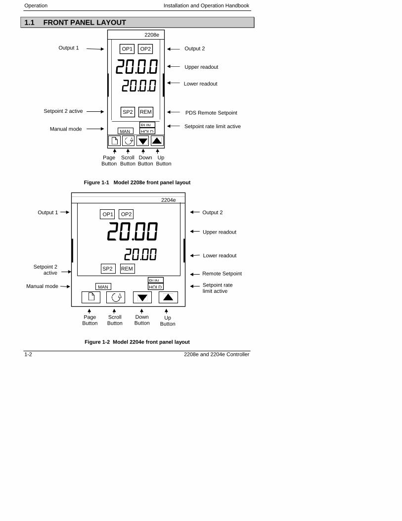
1.1 FRONT PANEL LAYOUT
Figure 1-1 Model 2208e front panel layout
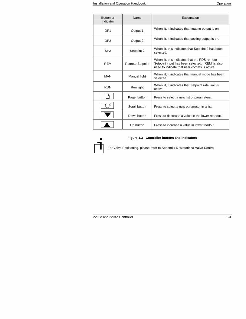
Figure 1-2 Model 2204e front panel layout
PageButton
ScrollButton
DownButton
UpButton
Manual mode
Setpoint 2 active PDS Remote Setpoint
Setpoint rate limit active
�������������
OP1 OP2
SP2 REM
2208e
Output 1 Output 2
Upper readout
Lower readout
MANRUNHOLD
DownButton
Manual mode
PageButton
ScrollButton
UpButton
Remote Setpoint
Output 2
Upper readout
Lower readout
Output 1
Setpoint 2active
Setpoint ratelimit active
�������������
OP1 OP2
2204e
SP2 REM
MANRUNHOLD
Installation and Operation Handbook Operation
2208e and 2204e Controller 1-3
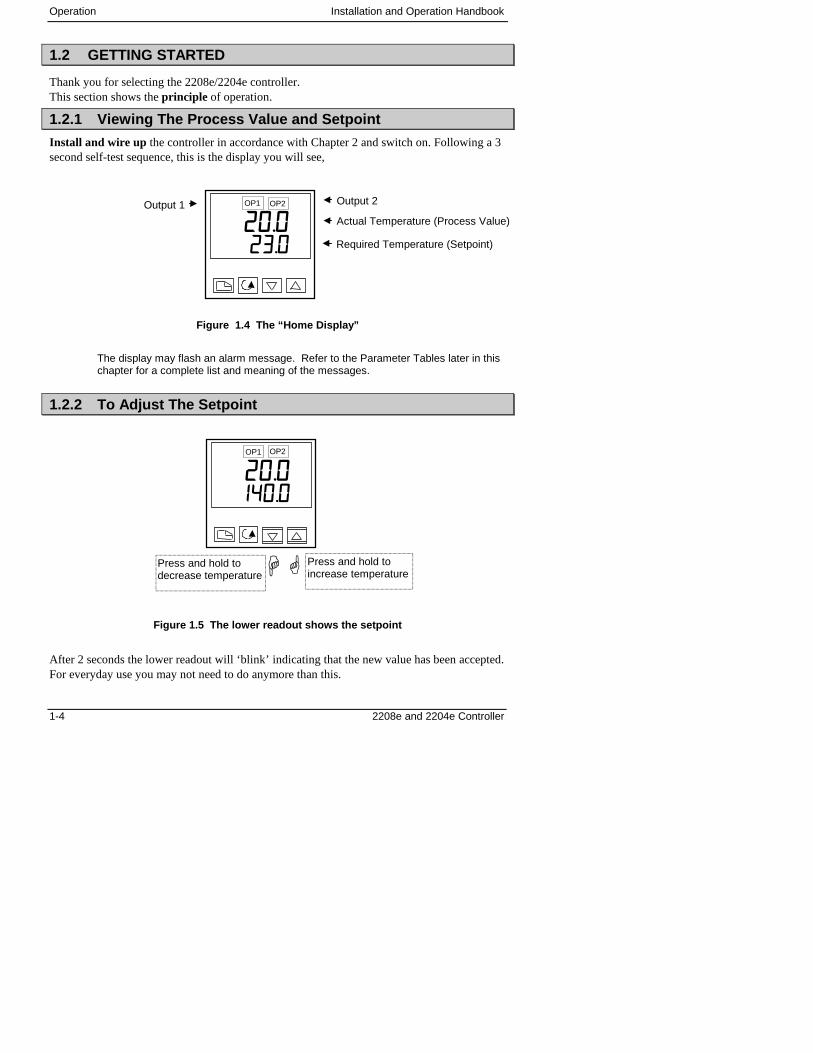
Button orindicator
Name Explanation
OP1 Output 1When lit, it indicates that heating output is on.
OP2 Output 2When lit, it indicates that cooling output is on.
SP2 Setpoint 2When lit, this indicates that Setpoint 2 has beenselected.
REM Remote SetpointWhen lit, this indicates that the PDS remoteSetpoint input has been selected. ‘REM’ is alsoused to indicate that user comms is active.
MAN Manual lightWhen lit, it indicates that manual mode has beenselected
RUN Run lightWhen lit, it indicates that Setpoint rate limit isactive.
Page button Press to select a new list of parameters.
Scroll button Press to select a new parameter in a list.
Down button Press to decrease a value in the lower readout.
Up button Press to increase a value in lower readout.
Figure 1.3 Controller buttons and indicators
For Valve Positioning, please refer to Appendix D ‘Motorised Valve Control�
Operation Installation and Operation Handbook
1-4 2208e and 2204e Controller
1.2 GETTING STARTED
Thank you for selecting the 2208e/2204e controller.This section shows the principle of operation.
1.2.1 Viewing The Process Value and Setpoint
Install and wire up the controller in accordance with Chapter 2 and switch on. Following a 3second self-test sequence, this is the display you will see,
Figure 1.4 The “Home Display”
The display may flash an alarm message. Refer to the Parameter Tables later in thischapter for a complete list and meaning of the messages.
1.2.2 To Adjust The Setpoint
Figure 1.5 The lower readout shows the setpoint
After 2 seconds the lower readout will ‘blink’ indicating that the new value has been accepted.For everyday use you may not need to do anymore than this.
Output 1
Actual Temperature (Process Value)
Output 2
Required Temperature (Setpoint)
��������
OP1 OP2
��Press and hold toincrease temperature
Press and hold todecrease temperature
���������
OP1 OP2
Installation and Operation Handbook Operation
2208e and 2204e Controller 1-5
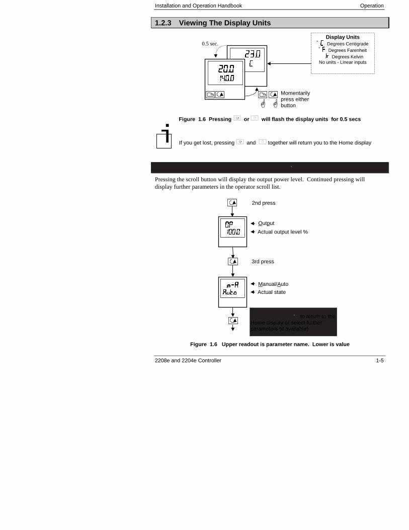
1.2.3 Viewing The Display Units
Figure 1.6 Pressing or will flash the display units for 0.5 secs
If you get lost, pressing and together will return you to the Home display
1.2.4 Use Of The “SCROLL” Button
Pressing the scroll button will display the output power level. Continued pressing willdisplay further parameters in the operator scroll list.
Figure 1.6 Upper readout is parameter name. Lower is value
Keep pressing to return to theHome display or select furtherparameters (if available)
2nd press
3rd press
Output
Actual output level %��������������
Manual/Auto
Actual state������
��������
Display Units���� Degrees Centigrade�� Degrees Farenheit�� Degrees Kelvin
No units - Linear inputs
Momentarilypress eitherbutton��
0.5 sec.
��������
������������
�
Operation Installation and Operation Handbook
1-6 2208e and 2204e Controller
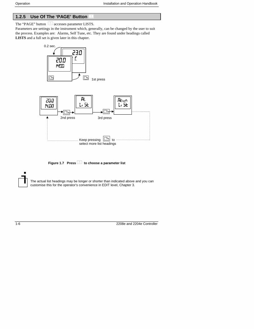
1.2.5 Use Of The ‘PAGE’ Button
The “PAGE” button accesses parameter LISTS.Parameters are settings in the instrument which, generally, can be changed by the user to suitthe process. Examples are: Alarms, Self Tune, etc. They are found under headings calledLISTS and a full set is given later in this chapter.
Figure 1.7 Press to choose a parameter list
The actual list headings may be longer or shorter than indicated above and you cancustomise this for the operator’s convenience in EDIT level, Chapter 3.
Keep pressing toselect more list headings
1st press
0.2 sec.
��������������������
��
3rd press2nd press
����
� ��� ����������� ��� ��
����
����
�
Installation and Operation Handbook Operation
2208e and 2204e Controller 1-7
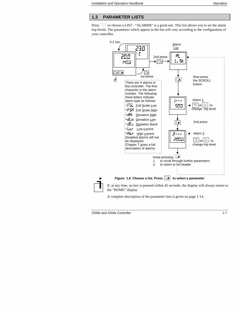
1.3 PARAMETER LISTS
Press to choose a LIST - “ALARMS” is a good one. This list allows you to set the alarmtrip levels. The parameters which appear in the list will vary according to the configuration ofyour controller.
Figure 1.8 Choose a list. Press to select a parameter
If, at any time, no key is pressed within 45 seconds, the display will always return tothe “HOME” display.
A complete description of the parameter lists is given on page 1-14.
or tochange trip level
or tochange trip level
1st press�
2nd press
0.2 sec.
������������
�������
There are 4 alarms inthe controller. The firstcharacter is the alarmnumber. The followingthree letters indicatealarm type as follows:
�� �� Full Scale Low
������ Full Scale High
�������� Deviation High
��� �� � Deviation Low
�������� Deviation Band
�� �� �� Low current
�������� High currentDisabled alarms will notbe displayed.Chapter 7 gives a fulldescription of alarms.
Alarm List
Alarm 1
Now pressthe SCROLLbutton
2nd press
����
� ��� ��
��������
����
��������
����
Keep pressing1. to scroll through further parameters2. to return to list header
Alarm 2
�
Operation Installation and Operation Handbook
1-8 2208e and 2204e Controller
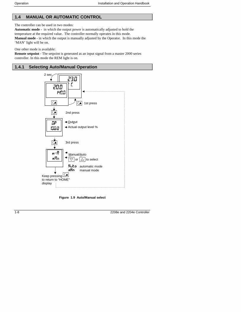
1.4 MANUAL OR AUTOMATIC CONTROL
The controller can be used in two modes:Automatic mode - in which the output power is automatically adjusted to hold thetemperature at the required value. The controller normally operates in this mode.Manual mode - in which the output is manually adjusted by the Operator. In this mode the‘MAN’ light will be on.
One other mode is available:Remote setpoint - The setpoint is generated as an input signal from a master 2000 seriescontroller. In this mode the REM light is on.
1.4.1 Selecting Auto/Manual Operation
Figure 1.9 Auto/Manual select
or to select
2 sec.
������������
��������������
1st press
Output
Actual output level %
Manual/Auto
�������� automatic mode������ manual mode
2nd press
3rd press
����
����
������
������
Keep pressingto return to “HOME”display
Installation and Operation Handbook Operation
2208e and 2204e Controller 1-9
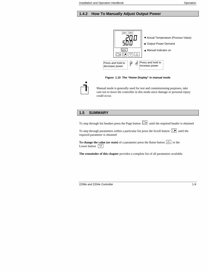
1.4.2 How To Manually Adjust Output Power
Figure 1.10 The “Home Display” in manual mode
1.5 SUMMARY
To step through list headers press the Page button until the required header is obtained
To step through parameters within a particular list press the Scroll button until therequired parameter is obtained
To change the value (or state) of a parameter press the Raise button or theLower button
The remainder of this chapter provides a complete list of all parameters available.
Actual Temperature (Process Value) ���������
OP1 OP2
Output Power Demand
Manual Indicator onMAN
��Press and hold toincrease power
Press and hold todecrease power
Manual mode is generally used for test and commissioning purposes, takecare not to leave the controller in this mode since damage or personal injurycould occur.
�
Operation Installation and Operation Handbook
1-10 2208e and 2204e Controller
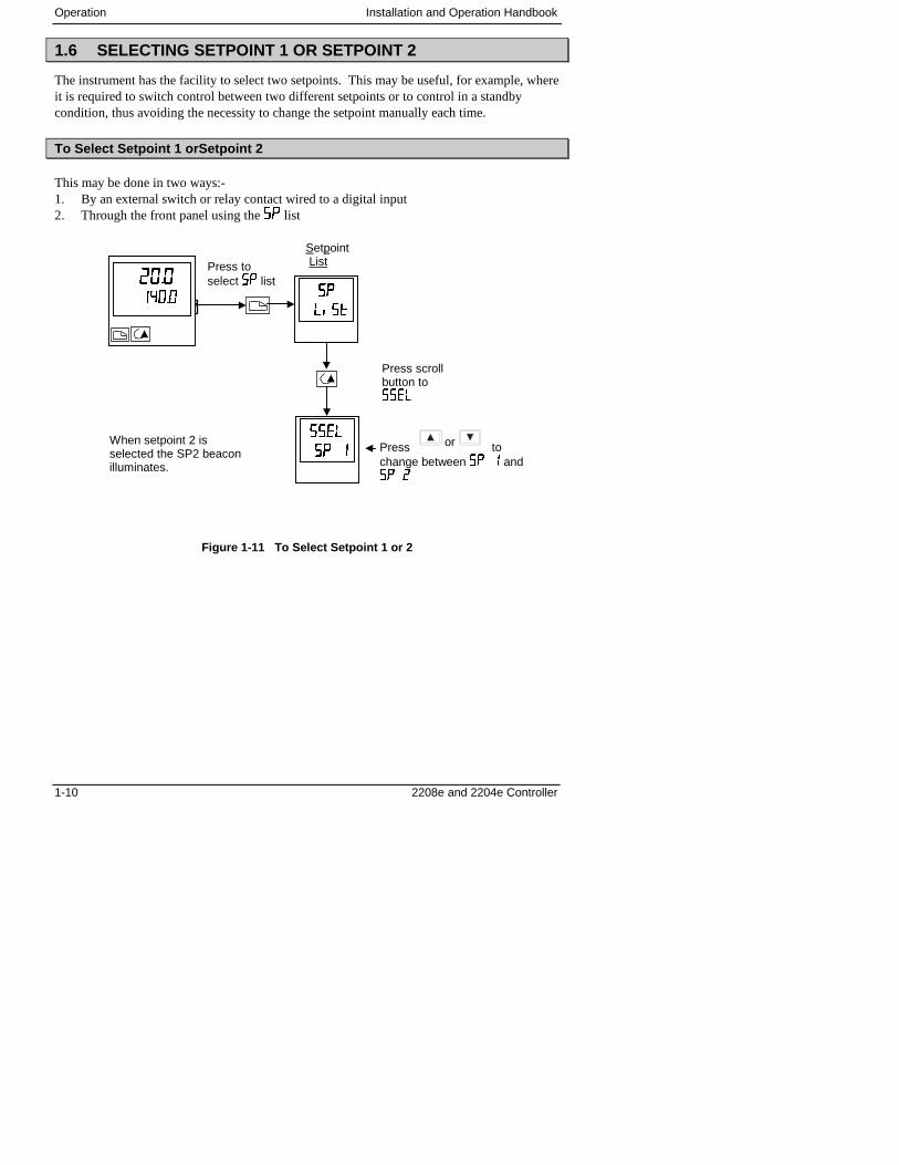
1.6 SELECTING SETPOINT 1 OR SETPOINT 2
The instrument has the facility to select two setpoints. This may be useful, for example, whereit is required to switch control between two different setpoints or to control in a standbycondition, thus avoiding the necessity to change the setpoint manually each time.
To Select Setpoint 1 orSetpoint 2
This may be done in two ways:-1. By an external switch or relay contact wired to a digital input2. Through the front panel using the �� list
Figure 1-11 To Select Setpoint 1 or 2
Press toselect �� list����
���
Setpoint List
Press scrollbutton to���
����
� ��� ��
��������
�� ��� � Press or tochange between �� � and�� �
When setpoint 2 isselected the SP2 beaconilluminates.
Installation and Operation Handbook Operation
2208e and 2204e Controller 1-11
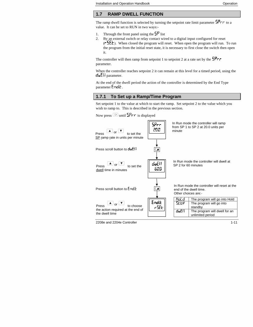
1.7 RAMP DWELL FUNCTION
The ramp dwell function is selected by turning the setpoint rate limit parameter ���� to avalue. It can be set to RUN in two ways:-
1. Through the front panel using the �� list2. By an external switch or relay contact wired to a digital input configured for reset
(����). When closed the program will reset. When open the program will run. To runthe program from the initial reset state, it is necessary to first close the switch then openit.
The controller will then ramp from setpoint 1 to setpoint 2 at a rate set by the ����parameter.
When the controller reaches setpoint 2 it can remain at this level for a timed period, using the���� parameter.
At the end of the dwell period the action of the controller is determined by the End Typeparameter �����.
1.7.1 To Set up a Ramp/Time Program
Set setpoint 1 to the value at which to start the ramp. Set setpoint 2 to the value which youwish to ramp to. This is described in the previous section.
Now press until ���� is displayed
In Run mode the controller will rampfrom SP 1 to SP 2 at 20.0 units perminute
Press scroll button to ����
��������
��������
��������
��������
Press or to set theSP ramp rate in units per minute
Press or to set thedwell time in minutes
In Run mode the controller will dwell atSP 2 for 60 minutes
Press scroll button to �����
����������
��������Press or to choosethe action required at the end ofthe dwell time
In Run mode the controller will reset at theend of the dwell time.Other choices are:-
�� � The program will go into Hold���� The program will go into
standby�� � The program will dwell for an
unlimited period
Operation Installation and Operation Handbook
1-12 2208e and 2204e Controller
Figure 1-12 Ramp/Dwell Program
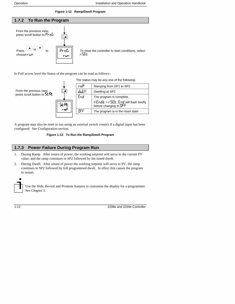
1.7.2 To Run the Program
In Full access level the Status of the program can be read as follows:-
A program may also be reset or run using an external switch contact if a digital input has beenconfigured. See Configuration section.
Figure 1-13 To Run the Ramp/Dwell Program
1.7.3 Power Failure During Program Run
1. During Ramp. After return of power, the working setpoint will servo to the current PVvalue, and the ramp continues to SP2 followed by the timed dwell.
2. During Dwell. After return of power the working setpoint will servo to PV, the rampcontinues to SP2 followed by full programmed dwell. In effect this causes the programto restart.
Use the Hide, Reveal and Promote features to customise the display for a programmer.See Chapter 3.
From the previous view,press scroll button to ���!
��������
������
Press or tochoose ���
To reset the controller to start conditions, select����
�
From the previous view,press scroll button to ����
��������
�"#�"#
The status may be any one of the following:
�"# Ramping from SP1 to SP2
�� � Dwelling at SP2
��� The program is complete.
If ����� = ����, ��� will flash brieflybefore changing to $
$ The program is in the reset state
Installation and Operation Handbook Operation
2208e and 2204e Controller 1-13
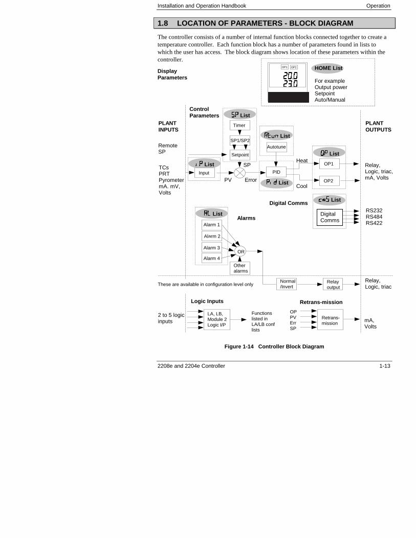
1.8 LOCATION OF PARAMETERS - BLOCK DIAGRAM
The controller consists of a number of internal function blocks connected together to create atemperature controller. Each function block has a number of parameters found in lists towhich the user has access. The block diagram shows location of these parameters within thecontroller.
DisplayParameters
Figure 1-14 Controller Block Diagram
Input PID
OP1
OP2Error
SP
PLANTINPUTS
PLANTOUTPUTS
Heat
Cool
AutotuneRemoteSP
TCsPRTPyrometermA. mV,Volts
Relay,Logic, triac,mA, Volts
Setpoint
SP1/SP2
Timer
PV
���� List
��%��% List
$�$� List
���� List
�������� List
��������
OP1 OP2
HOME List
For exampleOutput powerSetpointAuto/Manual
ControlParameters
DigitalComms
RS232RS484RS422
�"&�"& ListDigital Comms
Retrans-mission
mA,Volts
OPPVErrSP
LA, LB,Module 2Logic I/P
2 to 5 logicinputs
Functionslisted inLA/LB conflists
Relayoutput
Relay,Logic, triac
Alarm 1
Alarm 2
Alarm 3
Alarm 4
Otheralarms
Normal/Invert
OR
� � List
These are available in configuration level only
Alarms
Logic Inputs Retrans-mission
Operation Installation and Operation Handbook
1-14 2208e and 2204e Controller
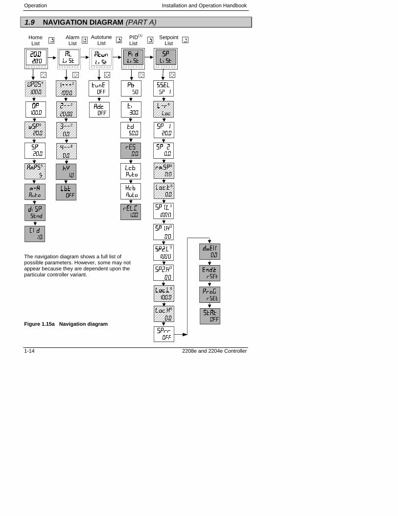
1.9 NAVIGATION DIAGRAM (PART A)
The navigation diagram shows a full list ofpossible parameters. However, some may notappear because they are dependent upon theparticular controller variant.
Figure 1.15a Navigation diagram
����������������
HomeList
��������
��������
��������������
PID(1)
List
� � ��������
AlarmList
AutotuneList
������������
SetpointList
$�
����
�"��5
"��
���
����2
����
���2
�����
'��2
���
(��2
���
)���
���
��
���
��
�
)�
���
��
���
���
���
��
���
���
���
���
��
��8
� �
�� �
����
�� �
���
�"���8
���
����8
���
�� ��
���
���� 3
����
�����3
���
��� 8
����
����8
���
����
���
�����3
���
���� 3
����
*�$�4
����
+��9
����
��
����
����
����
�,%
��
-�
��
%���
���
�����
����
���!
����
����
���
���
���
Installation and Operation Handbook Operation
2208e and 2204e Controller 1-15
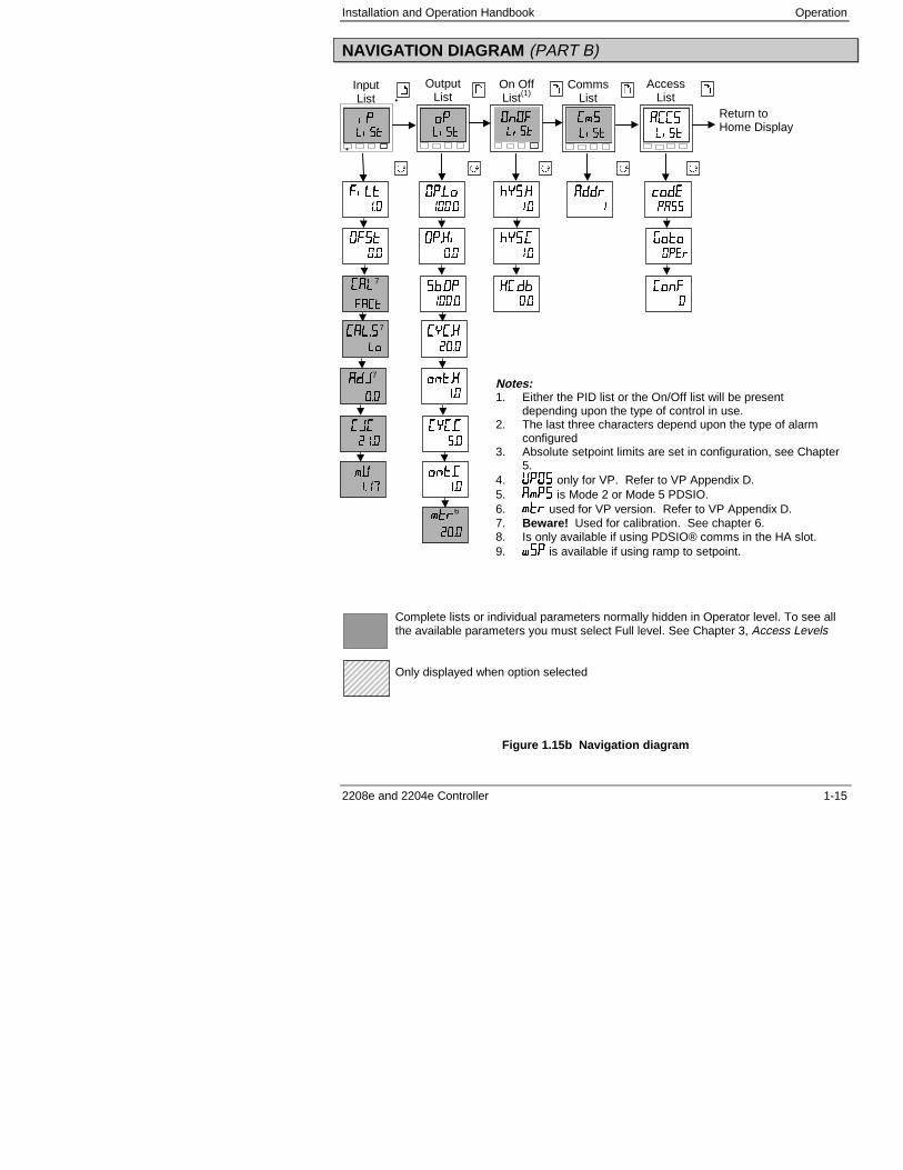
NAVIGATION DIAGRAM (PART B)
.
.
Complete lists or individual parameters normally hidden in Operator level. To see allthe available parameters you must select Full level. See Chapter 3, Access Levels
Only displayed when option selected
Figure 1.15b Navigation diagram
������
InputList
������
OutputList
�"�
����
CommsList
����
����
AccessList
$�$����
On OffList(1)
� �
��
�� 7
����
�� ��7
�
$�� �
����
$����
���
���$�
����
�����
����
Notes:1. Either the PID list or the On/Off list will be present
depending upon the type of control in use.2. The last three characters depend upon the type of alarm
configured3. Absolute setpoint limits are set in configuration, see Chapter
5.4. *�$� only for VP. Refer to VP Appendix D.5. �"#& is Mode 2 or Mode 5 PDSIO.6. "�� used for VP version. Refer to VP Appendix D.7. Beware! Used for calibration. See chapter 6.8. Is only available if using PDSIO® comms in the HA slot.9. +�� is available if using ramp to setpoint.
�����
��
�����
��
-����
��
-����
��
�����
���
����
��%�
����
!���
����
�����
��
���
�
Return toHome Display
$�)
���
���6
����
��.7
���
�.�
���
"*
��
Operation Installation and Operation Handbook
1-16 2208e and 2204e Controller
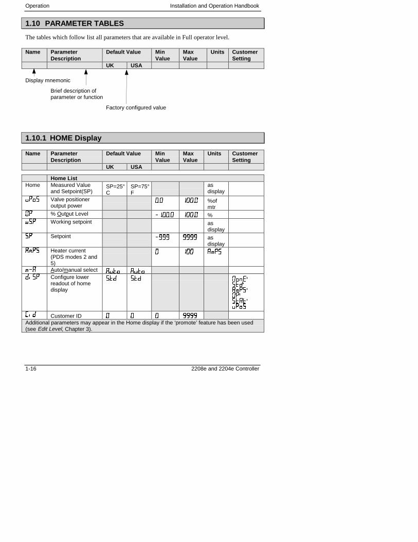
1.10 PARAMETER TABLES
The tables which follow list all parameters that are available in Full operator level.
Name ParameterDescription
Default Value MinValue
MaxValue
Units CustomerSetting
UK USA
Display mnemonic
Brief description ofparameter or function
Factory configured value
1.10.1 HOME Display
Name ParameterDescription
Default Value MinValue
MaxValue
Units CustomerSetting
UK USA
Home ListHome Measured Value
and Setpoint(SP)SP=25°C
SP=75°F
asdisplay
���� Valve positioneroutput power
��� ����� %ofmtr
$� % Output Level ������ ����� %��� Working setpoint as
display�� Setpoint �/// //// as
display�"�� Heater current
(PDS modes 2 and5)
� ��� �"#&
"�� Auto/manual select ���� �������� Configure lower
readout of homedisplay
��% ��% 0�� 1��%1�"��1$�1&���1����
��� Customer ID � � � ////Additional parameters may appear in the Home display if the ‘promote’ feature has been used(see Edit Level, Chapter 3).
Installation and Operation Handbook Operation
2208e and 2204e Controller 1-17
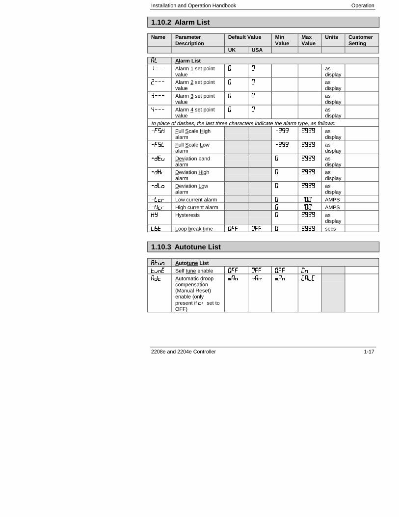
1.10.2 Alarm List
Name ParameterDescription
Default Value MinValue
MaxValue
Units CustomerSetting
UK USA
� � Alarm List
���� Alarm 1 set pointvalue
� � asdisplay
���� Alarm 2 set pointvalue
� � asdisplay
'��� Alarm 3 set pointvalue
� � asdisplay
(��� Alarm 4 set pointvalue
� � asdisplay
In place of dashes, the last three characters indicate the alarm type, as follows:
��� Full Scale Highalarm
�/// //// asdisplay
�� Full Scale Lowalarm
�/// //// asdisplay
�%�� Deviation bandalarm
� //// asdisplay
���� Deviation Highalarm
� //// asdisplay
�� � Deviation Lowalarm
� //// asdisplay
� �� Low current alarm � ��� AMPS
���� High current alarm � ��� AMPS
�2 Hysteresis � //// asdisplay
�� Loop break time $ $ � //// secs
1.10.3 Autotune List
�������� Autotune List
���� Self tune enable $ $ $ $�
��� Automatic droopcompensation(Manual Reset)enable (onlypresent if �� set toOFF)
��� ��� ��� �� �
Operation Installation and Operation Handbook
1-18 2208e and 2204e Controller
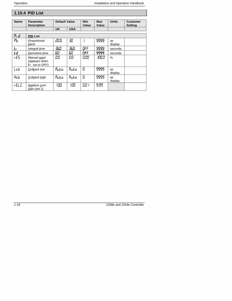
1.10.4 PID List
Name ParameterDescription
Default Value MinValue
MaxValue
Units CustomerSetting
UK USA
������ PID List
�� Proportionalband
���� '� � //// asdisplay
�� Integral time '�� '�� $ //// seconds
�� Derivative time �� �� $ //// seconds
��� Manual reset(appears when�� set to OFF)
��� ��� ���� ����� %
�� Cutback low ���� ���� � //// asdisplay
��� Cutback high ���� ���� � //// asdisplay
�� �� Relative coolgain (set 1)
���� ���� ���� /�//
Installation and Operation Handbook Operation
2208e and 2204e Controller 1-19
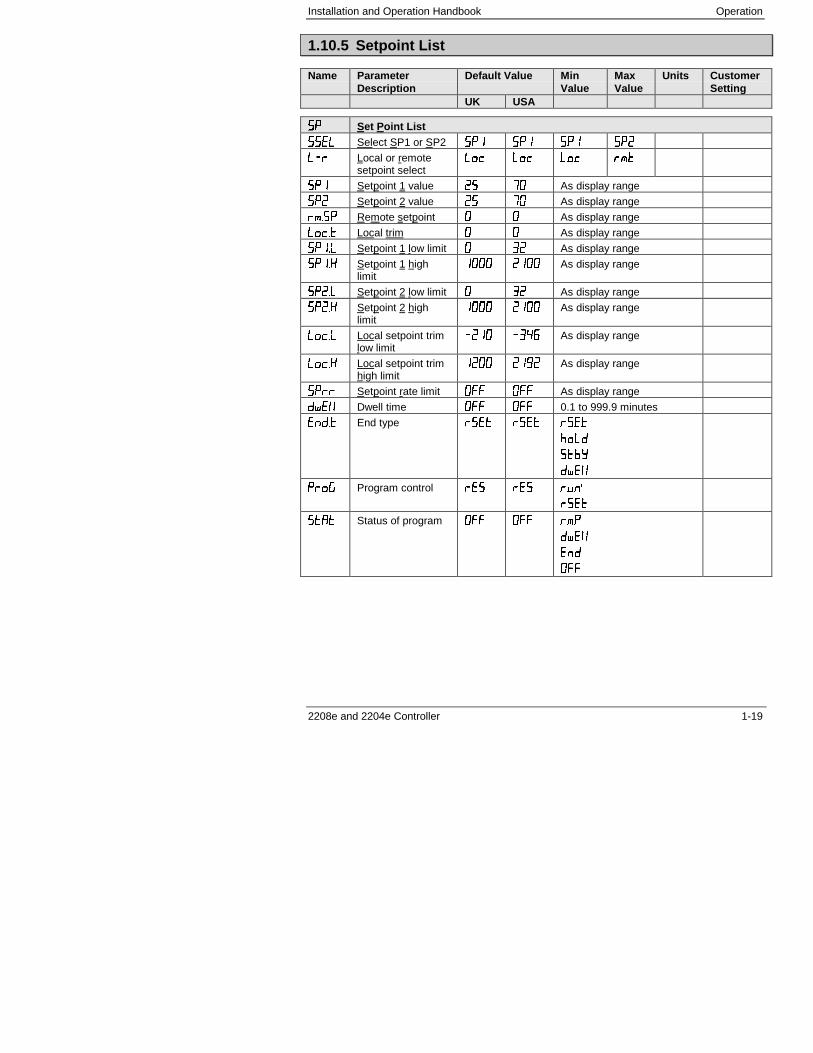
1.10.5 Setpoint List
Name ParameterDescription
Default Value MinValue
MaxValue
Units CustomerSetting
UK USA
���� Set Point List
��� Select SP1 or SP2 ��� ��� ��� ���
�� Local or remotesetpoint select
�� �� �� �"�
��� Setpoint 1 value �3 4� As display range
��� Setpoint 2 value �3 4� As display range
�"��� Remote setpoint � � As display range
���� Local trim � � As display range
���� Setpoint 1 low limit � '� As display range
����� Setpoint 1 highlimit
���� ���� As display range
���� Setpoint 2 low limit � '� As display range
����� Setpoint 2 highlimit
���� ���� As display range
��� Local setpoint trimlow limit
���� �'(� As display range
���� Local setpoint trimhigh limit
���� ��/� As display range
���� Setpoint rate limit $ $55 As display range
���� Dwell time $ $ 0.1 to 999.9 minutes
��%�� End type �& � �& � �& �
-� �
���2
�� �
���! Program control ��� ��� ���1
�& �
���� Status of program $55 $ �"#
�� �
��
$55

Operation Installation and Operation Handbook
1-20 2208e and 2204e Controller
Installation and Operation Handbook Operation
2208e and 2204e Controller 1-21
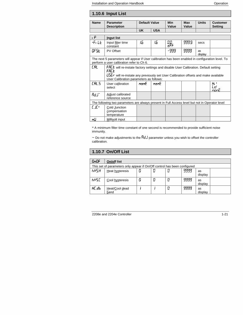
1.10.6 Input List
Name ParameterDescription
Default Value MinValue
MaxValue
Units CustomerSetting
UK USA
���� Input list
*� � Input filter timeconstant
��� ��� ����55
///�/ secs
$�� PV Offset �/// //// asdisplay
The next 5 parameters will appear if User calibration has been enabled in configuration level. Toperform a user calibration refer to Ch 6.
�� ��� will re-instate factory settings and disable User Calibration. Default setting���
6��� will re-instate any previously set User Calibration offsets and make availableUser Calibration parameters as follows:
�� �� User calibrationselect
��� ��� ��1 �1���
��7~ Adjust calibrated
reference source
The following two parameters are always present in Full Access level but not in Operator level
�.�� Cold Junctioncompensationtemperature
"* Millivolt input
* A minimum filter time constant of one second is recommended to provide sufficient noiseimmunity.
~ Do not make adjustments to the ��. parameter unless you wish to offset the controllercalibration.
1.10.7 On/Off List
$�$5$�$5 On/off listThis set of parameters only appear if On/Off control has been configured
-���� Heat hysteresis � � � //// asdisplay
-���� Cool hysteresis � � � //// asdisplay
����� Heat/Cool deadband
� � � //// asdisplay
Operation Installation and Operation Handbook
1-22 2208e and 2204e Controller
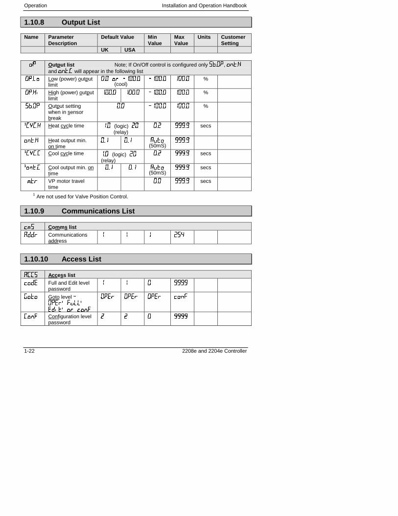
1.10.8 Output List
Name ParameterDescription
Default Value MinValue
MaxValue
Units CustomerSetting
UK USA
���� Outp ut list Note; If On/Off control is configured only ���$�, �����and ����� will appear in the following list
$�� � Low (power) outputlimit
��� �� ������(cool)
������ ����� %
$���� High (power) outputlimit
����� ����� ������ ����� %
���$� Output settingwhen in sensorbreak
��� ������ ����� %
1����� Heat cycle time ��� (logic) ��
(relay)��� ///�/ secs
����� Heat output min.on time
��� ��� ����(50mS)
///�/
1����� Cool cycle time ��� (logic) ��
(relay)��� ///�/ secs
1����� Cool output min. on
time��� ��� ����
(50mS)///�/ secs
"�� VP motor traveltime
��� ///�/ secs
1 Are not used for Valve Position Control.
1.10.9 Communications List
�"��"� Comms list
���� Communicationsaddress
� � � �3(
1.10.10 Access List
�������� Acces s list
���� Full and Edit levelpassword
� � � ////
!��� Goto level �$���1� 1
����1�� ���
$��� $��� $��� ���
��� Configuration levelpassword
� � � ////
Installation and Operation Handbook Operation
2208e and 2204e Controller 1-23
1.11 ALARMS
Alarms are used to alert an operator when a pre-set level has been exceeded. They arenormally used to switch an output (see 1.10) – usually a relay – to provide external actions tothe process.
Soft Alarms are indication only and do not operate an output.
Events are generally defined as conditions, which occur as part of the operation of the plant.They do not require operator intervention and, therefore, do not cause an alarm message to bedisplayed. They can be attached to operate an output (relay) in the same way as an alarm.
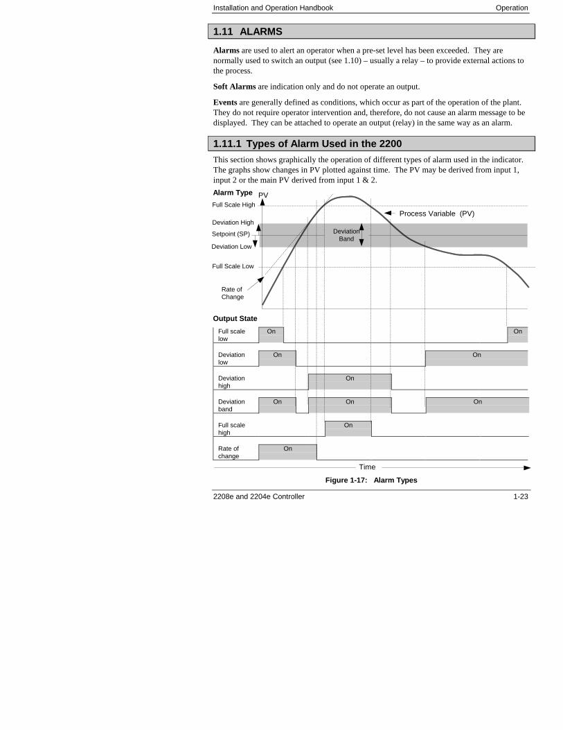
1.11.1 Types of Alarm Used in the 2200
This section shows graphically the operation of different types of alarm used in the indicator.The graphs show changes in PV plotted against time. The PV may be derived from input 1,input 2 or the main PV derived from input 1 & 2.
Full scalelow
On On
Deviationlow
On On
Deviationhigh
On
Deviationband
On On On
Full scalehigh
On
Rate ofchange
On
Figure 1-17: Alarm Types
Time
Setpoint (SP)
Full Scale High
Full Scale Low
Deviation High
Deviation Low
DeviationBand
PV
Rate ofChange
Process Variable (PV)
Alarm Type
Output State
Operation Installation and Operation Handbook
1-24 2208e and 2204e Controller
Hysteresis is the difference between the point at which the alarm switches ON and the point atwhich it switches OFF.It is used to prevent relay chatter.
Blocking Alarms only occur after the start up phase when the alarm has first entered a safestate. The alarm is only indicated the next time it is active. It is used, for example, to ignorestart up conditions which are not representative of running conditions.
Latching Alarms see 7.1.1.
Delay a settable time between an alarm occurring and it being displayed on the indicator
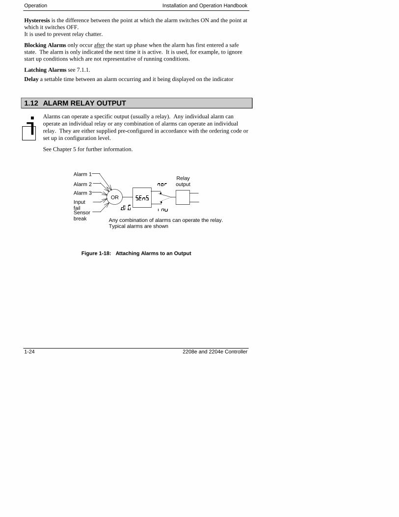
1.12 ALARM RELAY OUTPUT
Alarms can operate a specific output (usually a relay). Any individual alarm canoperate an individual relay or any combination of alarms can operate an individualrelay. They are either supplied pre-configured in accordance with the ordering code orset up in configuration level.
See Chapter 5 for further information.
Figure 1-18: Attaching Alarms to an Output
�,!
����
���
���
Relayoutput
Any combination of alarms can operate the relay.Typical alarms are shown
OR
Alarm 1
Alarm 2
Sensorbreak
Inputfail
Alarm 3
�
Installation and Operation Handbook Operation
2208e and 2204e Controller 1-25
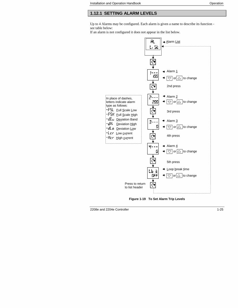
1.12.1 SETTING ALARM LEVELS
Up to 4 Alarms may be configured. Each alarm is given a name to describe its function -see table below:If an alarm is not configured it does not appear in the list below.
Figure 1-19 To Set Alarm Trip Levels
��������������
��������������
����������
��������
����
� ��� ��
�� ��� �$$
In place of dashes,letters indicate alarmtype as follows:
�� Full Scale Low
��� Full Scale High
���� Deviation Band
���� Deviation High
�� � Deviation Low
� �� Low current
���� High current
Alarm List
Alarm 1
2nd press
or to change
3rd press
4th press
5th press
Alarm 2
Alarm 3
Alarm 4
Loop break time
or to change
or to change
or to change
or to change
Press to returnto list header

Operation Installation and Operation Handbook
1-26 2208e and 2204e Controller
Installation and Operation Handbook Operation
2208e and 2204e Controller 1-27
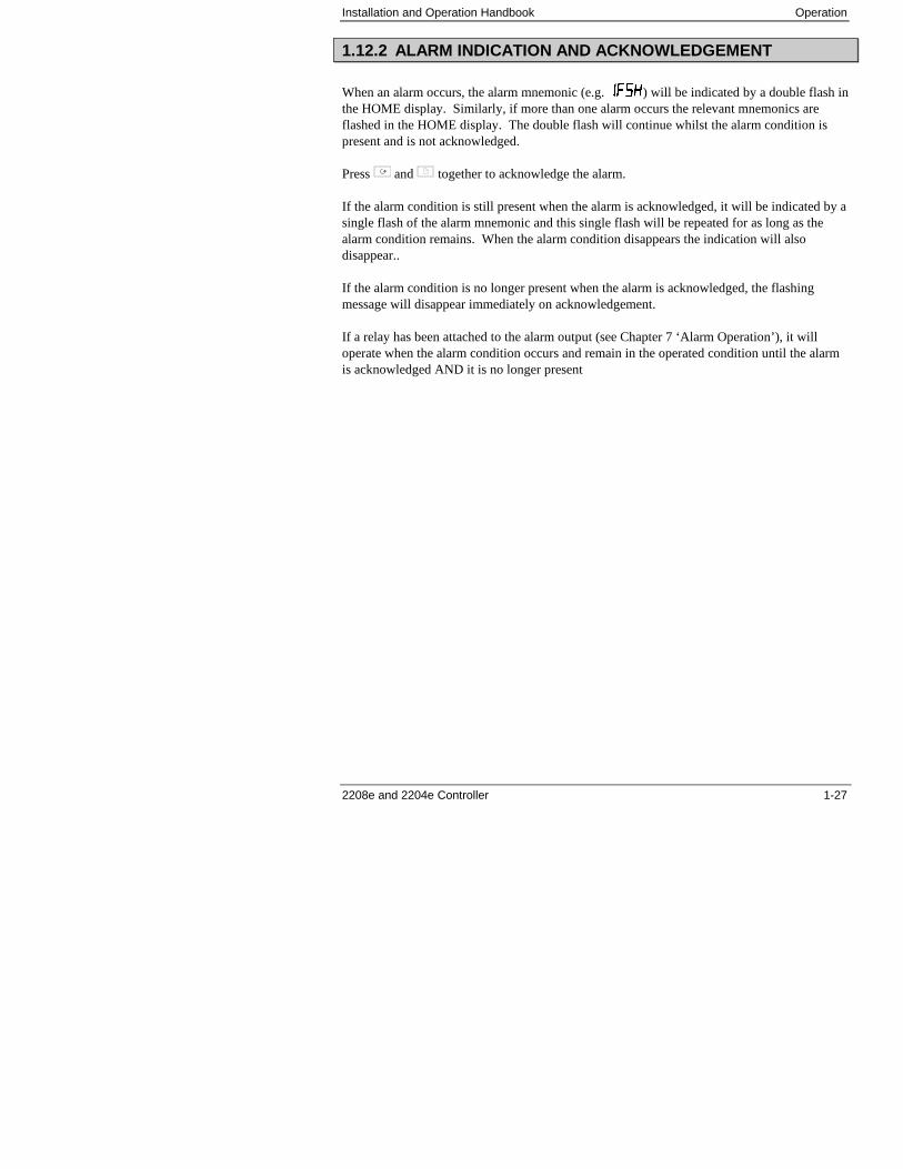
1.12.2 ALARM INDICATION AND ACKNOWLEDGEMENT
When an alarm occurs, the alarm mnemonic (e.g. � �!) will be indicated by a double flash inthe HOME display. Similarly, if more than one alarm occurs the relevant mnemonics areflashed in the HOME display. The double flash will continue whilst the alarm condition ispresent and is not acknowledged.
Press and together to acknowledge the alarm.
If the alarm condition is still present when the alarm is acknowledged, it will be indicated by asingle flash of the alarm mnemonic and this single flash will be repeated for as long as thealarm condition remains. When the alarm condition disappears the indication will alsodisappear..
If the alarm condition is no longer present when the alarm is acknowledged, the flashingmessage will disappear immediately on acknowledgement.
If a relay has been attached to the alarm output (see Chapter 7 ‘Alarm Operation’), it willoperate when the alarm condition occurs and remain in the operated condition until the alarmis acknowledged AND it is no longer present
Operation Installation and Operation Handbook
1-28 2208e and 2204e Controller
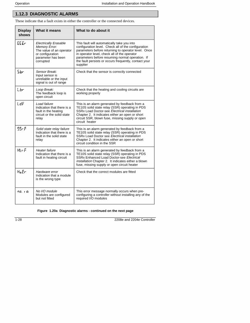
1.12.3 DIAGNOSTIC ALARMS
These indicate that a fault exists in either the controller or the connected devices.
Displayshows
What it means What to do about it
����� Electrically ErasableMemory Error:The value of an operatoror configurationparameter has beencorrupted
This fault will automatically take you intoconfiguration level. Check all of the configurationparameters before returning to operator level. Oncein operator level, check all of the operatorparameters before resuming normal operation. Ifthe fault persists or occurs frequently, contact yoursupplier
���� Sensor Break:Input sensor isunreliable or the inputsignal is out of range
Check that the sensor is correctly connected
��� Loop Break:The feedback loop isopen circuit
Check that the heating and cooling circuits areworking properly
�� Load failureIndication that there is afault in the heatingcircuit or the solid staterelay
This is an alarm generated by feedback from aTE10S solid state relay (SSR) operating in PDSSSRx Load Doctor-see Electrical installationChapter 2. It indicates either an open or shortcircuit SSR, blown fuse, missing supply or opencircuit heater
���� Solid state relay failureIndication that there is afault in the solid staterelay
This is an alarm generated by feedback from aTE10S solid state relay (SSR) operating in PDSSSRx Load Doctor see Electrical installationChapter 2. It indicates either an open or shortcircuit condition in the SSR
���� Heater failureIndication that there is afault in heating circuit
This is an alarm generated by feedback from aTE10S solid state relay (SSR) operating in PDSSSRx Enhanced Load Doctor-see Electricalinstallation Chapter 2. It indicates either a blownfuse, missing supply or open circuit heater
�+��� Hardware errorIndication that a moduleis the wrong type
Check that the correct modules are fitted
��� �� No I/O moduleModules are configuredbut not fitted
This error message normally occurs when pre-configuring a controller without installing any of therequired I/O modules
Figure 1.20a Diagnostic alarms - continued on the next page
Installation and Operation Handbook Operation
2208e and 2204e Controller 1-29
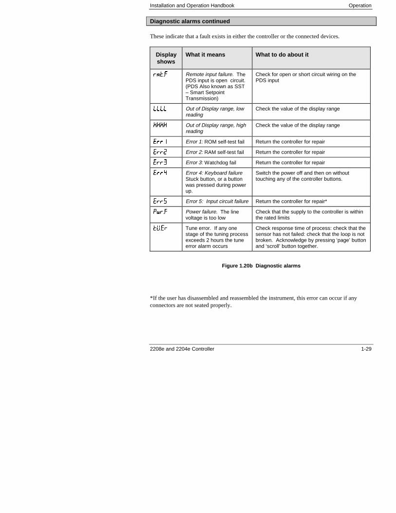
Diagnostic alarms continued
These indicate that a fault exists in either the controller or the connected devices.
Displayshows
What it means What to do about it
�"�� Remote input failure. ThePDS input is open circuit.(PDS Also known as SST– Smart SetpointTransmission)
Check for open or short circuit wiring on thePDS input
Out of Display range, lowreading
Check the value of the display range
���� Out of Display range, highreading
Check the value of the display range
���� Error 1: ROM self-test fail Return the controller for repair
���� Error 2: RAM self-test fail Return the controller for repair
���' Error 3: Watchdog fail Return the controller for repair
���( Error 4: Keyboard failureStuck button, or a buttonwas pressed during powerup.
Switch the power off and then on withouttouching any of the controller buttons.
���3 Error 5: Input circuit failure Return the controller for repair*
���� Power failure. The linevoltage is too low
Check that the supply to the controller is withinthe rated limits
)6��� Tune error. If any onestage of the tuning processexceeds 2 hours the tuneerror alarm occurs
Check response time of process: check that thesensor has not failed: check that the loop is notbroken. Acknowledge by pressing ‘page’ buttonand ‘scroll’ button together.
Figure 1.20b Diagnostic alarms
*If the user has disassembled and reassembled the instrument, this error can occur if anyconnectors are not seated properly.

Operation Installation and Operation Handbook
1-30 2208e and 2204e Controller
Installation and Operation Handbook Installation
2208e and 2204e Controller 2-1
2 Chapter 2 INSTALLATION
2 Chapter 2 INSTALLATION.................................................1
2.1 INSTRUMENT LAYOUTS.................................................................. 22.1.2 Outline Dimensions Model 2208e ...........................................................32.1.3 Outline Dimensions Model 2204e ...........................................................3
2.2 INTRODUCTION ................................................................................ 42.2.2 Controller labels ......................................................................................4
2.3 MECHANICAL INSTALLATION......................................................... 42.3.2 Unplugging and plugging-in the controller ..............................................4
2.4 WIRING .............................................................................................. 52.4.2 Wire Sizes...............................................................................................62.4.3 Wiring connections .................................................................................62.4.4 Sensor input connections .......................................................................72.4.5 Outputs 1 and 2 connections ..................................................................7
2.5 PDS MODES ...................................................................................... 8
2.6 SNUBBERS........................................................................................ 8
2.7 TYPICAL SINGLE LOOP WIRING DIAGRAM .................................. 9
2.8 RS 232/485/422 COMMUNICATION CONNECTIONS.................... 102.8.2 Wiring of EIA-485 serial communication links ......................................11
2.9 DEVICENET WIRING TO SERIES 2200E CONTROLLERS........... 122.9.2 DeviceNet Terminal Functions..............................................................122.9.3 Wiring Interconnections for DeviceNet Communications......................13
Installation Installation and Operation Handbook
2-2 2208e and 2204e Controller
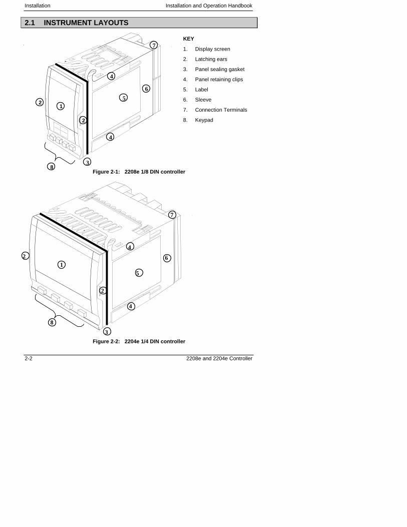
2.1 INSTRUMENT LAYOUTS
Figure 2-1: 2208e 1/8 DIN controller
Figure 2-2: 2204e 1/4 DIN controller
3
4
4
5
6
7
8
KEY
1. Display screen
2. Latching ears
3. Panel sealing gasket
4. Panel retaining clips
5. Label
6. Sleeve
7. Connection Terminals
8. Keypad
2
2
1
1
2
2
3
4
4
5
6
7
8
Installation and Operation Handbook Installation
2208e and 2204e Controller 2-3
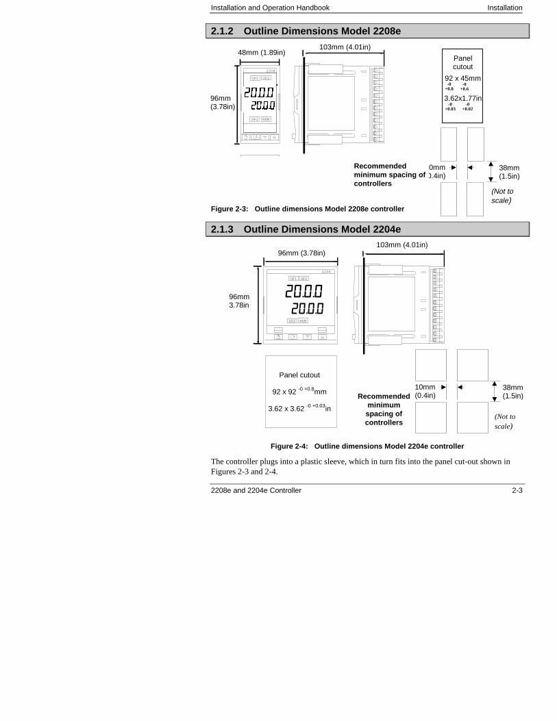
2.1.2 Outline Dimensions Model 2208e
Figure 2-3: Outline dimensions Model 2208e controller
2.1.3 Outline Dimensions Model 2204e
Figure 2-4: Outline dimensions Model 2204e controller
The controller plugs into a plastic sleeve, which in turn fits into the panel cut-out shown inFigures 2-3 and 2-4.
2208
OP1 OP2
SP2 REM
Panelcutout
92 x 45mm
3.62x1.77in
-0+0.8
-0+0.6
-0+0.03
-0+0.02
103mm (4.01in)48mm (1.89in)
96mm(3.78in)
38mm(1.5in)
10mm(0.4in)
(Not toscale)
Recommendedminimum spacing ofcontrollers
������������������
2204
OP1 OP2
SP2 REM
Panel cutout
92 x 92 -0 +0.8mm
3.62 x 3.62 -0 +0.03in
103mm (4.01in)96mm (3.78in)
96mm3.78in
Recommendedminimumspacing ofcontrollers
38mm(1.5in)
10mm(0.4in)
(Not toscale)
������
�������
Installation Installation and Operation Handbook
2-4 2208e and 2204e Controller
2.2 INTRODUCTION
The Models 2208e and 2204e are precision temperature controllers with self tuning. Theyhave a modular hardware construction which provides two control outputs, two alarm relaysand one communications port. Two logic inputs are provided as standard. In addition theModel 2204e has an optional plug-in 10A relay heating output.
2.2.2 Controller labels
The labels on the sides of the controller identify the ordering code, the serial number, and thewiring connections.
Appendix A, Understanding the Ordering Code explains the hardware and softwareconfiguration of your particular controller.
2.3 MECHANICAL INSTALLATION
To install the controller
1. Cut the panel to the relevant hole size shown in Figure 2-3 and 2.4.
2. Insert the controller through the front of this cutout.
3. Spring the upper and lower panel retaining clips into place. Secure the controller inposition by holding it level and pushing both retaining clips forward.
Note: If the panel retaining clips subsequently need removing, they can be unhooked from theside with either your fingers or a screwdriver.
2.3.2 Unplugging and plugging-in the controller
The controller can be unplugged from its sleeve by easing the latching ears outwards andpulling it forward out of the sleeve. When plugging the controller back into its sleeve, ensurethat the latching ears click into place to maintain moisture sealing protection.
Installation and Operation Handbook Installation
2208e and 2204e Controller 2-5
2.4 WIRING
Please read Appendix B, Safety and EMC information before proceeding.
WARNINGPlease ensure that the controller is correctly configured for yourapplication. Incorrect configuration could result in damage to theprocess being controlled, and/or personal injury. The controller mayeither have been configured when ordered, or may need configuringnow . See Chapter 5, Configuration.
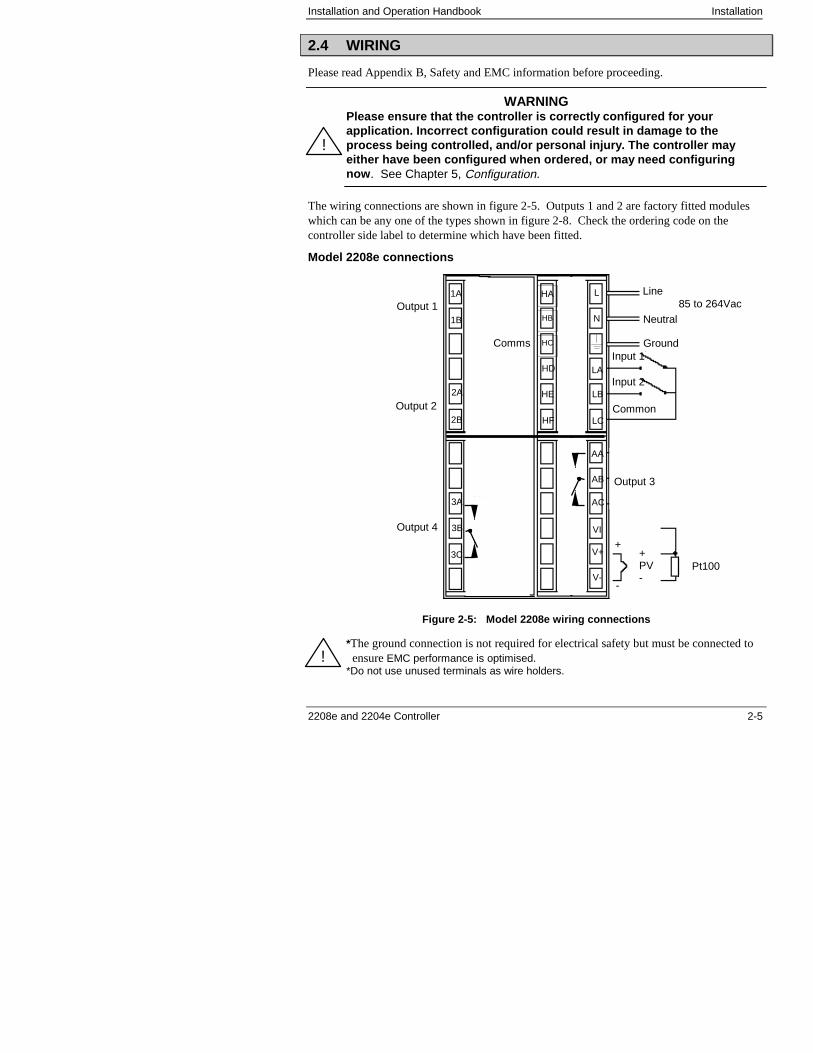
The wiring connections are shown in figure 2-5. Outputs 1 and 2 are factory fitted moduleswhich can be any one of the types shown in figure 2-8. Check the ordering code on thecontroller side label to determine which have been fitted.
Model 2208e connections
Figure 2-5: Model 2208e wiring connections
*The ground connection is not required for electrical safety but must be connected toensure EMC performance is optimised.
*Do not use unused terminals as wire holders.
Pt100
N
L
V+
VI
V-
Line
Neutral
Ground*
+
-
+PV-
2B
2A
1B
1A
HF
HD
HE
Common
Input 1
Input 2
85 to 264Vac
LC
LA
LB
AC
AB
Output 1
3B
3A
3C
Output 2
Output 4
Output 3
AA
HB
HC
HA
Comms
!
!
Installation Installation and Operation Handbook
2-6 2208e and 2204e Controller
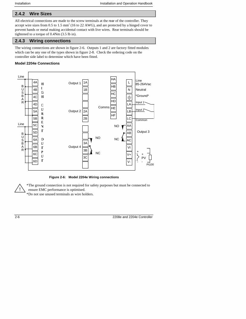
2.4.2 Wire Sizes
All electrical connections are made to the screw terminals at the rear of the controller. Theyaccept wire sizes from 0.5 to 1.5 mm2 (16 to 22 AWG), and are protected by a hinged cover toprevent hands or metal making accidental contact with live wires. Rear terminals should betightened to a torque of 0.4Nm (3.5 lb in).
2.4.3 Wiring connections
The wiring connections are shown in figure 2-6. Outputs 1 and 2 are factory fitted moduleswhich can be any one of the types shown in figure 2-8. Check the ordering code on thecontroller side label to determine which have been fitted.
Model 2204e Connections
Figure 2-6: Model 2204e Wiring connections
*The ground connection is not required for safety purposes but must be connected toensure EMC performance is optimised.
*Do not use unused terminals as wire holders.
Input 1
Neutral
*Ground*
+
-
+PV-
85-264VacHIGH
CURRENT
OUTPUT
Pt100
Output 1
Output 2
4B
4C
4D
5A
5B
5D
6A
6B
6C
6D
5C
1B
2A
2B
1A
3A
3B
3C
N
LA
LB
LC
L
AB
AC
VI
V+
V-
AA
HB
HC
HD
HE
HF
HA
Line
BUSBAR
Line
BUSBAR
Output 4
Output 3
Input 2
Common
Comms
Line4A
NO
NO
NC
NC
!
Installation and Operation Handbook Installation
2208e and 2204e Controller 2-7
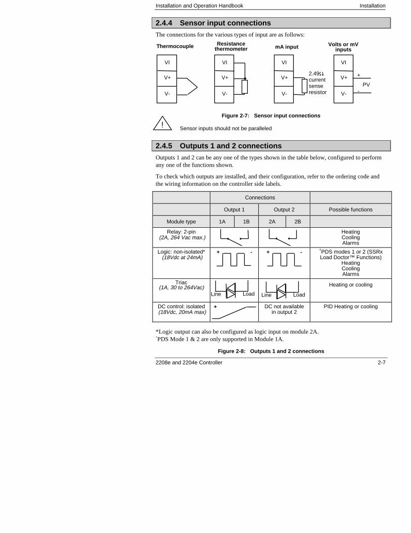
2.4.4 Sensor input connections
The connections for the various types of input are as follows:
Figure 2-7: Sensor input connections
Sensor inputs should not be paralleled
2.4.5 Outputs 1 and 2 connections
Outputs 1 and 2 can be any one of the types shown in the table below, configured to performany one of the functions shown.
To check which outputs are installed, and their configuration, refer to the ordering code andthe wiring information on the controller side labels.
Connections
Output 1 Output 2 Possible functions
Module type 1A 1B 2A 2B
Relay: 2-pin (2A, 264 Vac max.)
HeatingCoolingAlarms
Logic: non-isolated* (18Vdc at 24mA)
+ - + - +PDS modes 1 or 2 (SSRxLoad Doctor™ Functions)
HeatingCoolingAlarms
Triac(1A, 30 to 264Vac) Heating or cooling
DC control: isolated (18Vdc, 20mA max)
+ - DC not availablein output 2
PID Heating or cooling
*Logic output can also be configured as logic input on module 2A.+PDS Mode 1 & 2 are only supported in Module 1A.
Figure 2-8: Outputs 1 and 2 connections
VI
V+
V-
VI
V+
V-
VI
V+
V-
VI
V+
V-
Thermocouple Resistancethermometer mA input Volts or mV
inputs
+
-PV
2.49�currentsenseresistor
Line Load Line Load
!
Installation Installation and Operation Handbook
2-8 2208e and 2204e Controller
2.5 PDS MODES
PDS is a proprietary technique developed for bi-directional communication over a single pairof wires. There are several operating modes. In SSRx Load Doctor™ a logic output delivers a power demand signal to a TE10 solid state(SSR) relay and the SSR responds with a single load circuit failure message.In SSRx Enhanced Load Doctor™ a logic output delivers a power demand signal to an SSRand the SSR responds with the ON state rms load current, and two fault messages - SSR failureor heater circuit failure.
2.6 SNUBBERS
The controller is supplied with ‘snubbers’ (15nF +100�) which should be wired across therelay or triac outputs when switching inductive loads such as mechanical contactors andsolenoid valves. The snubbers are used to prolong contact life and to suppress interferencewhen switching such loads. Snubbers pass 0.6mA at 110Vac and 1.2mA at 240Vac, whichmay be sufficient to hold in high impedance relay coils. They should not, therefore, be used insuch installations.
WARNINGWhen a relay contact is used in an alarm circuit ensure that the current passingthrough the snubber when the relay contact is open does not hold in low powerelectrical loads and thereby interfere with the failsafe operation of the alarmcircuit.
!
Installation and Operation Handbook Installation
2208e and 2204e Controller 2-9
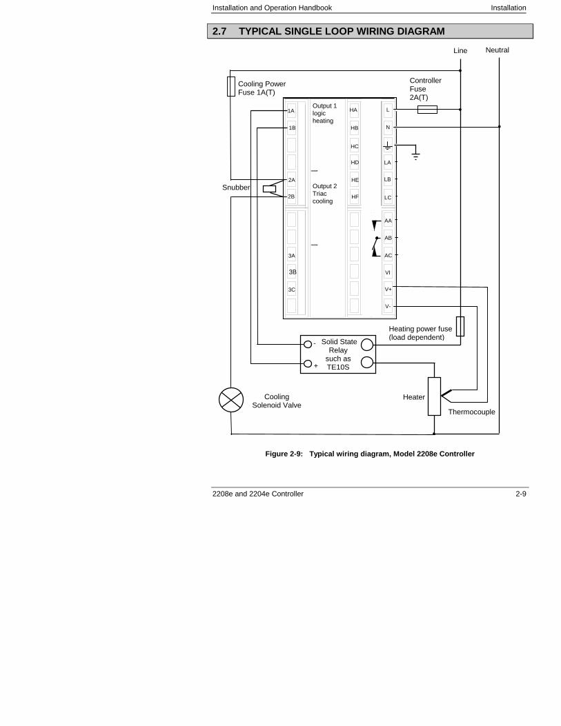
2.7 TYPICAL SINGLE LOOP WIRING DIAGRAM
Figure 2-9: Typical wiring diagram, Model 2208e Controller
Neutral
N
L
V+
VI
V-
+
-
+
PV
-
2B
2A
3B
3A
3C
1B
1A
HF
HD
HE
LC
LA
LB
AC
AA
AB
Cooling PowerFuse 1A(T)
Heating power fuse(load dependent)
CoolingSolenoid Valve
Heater
Thermocouple
-
ControllerFuse2A(T)
Solid StateRelay
such asTE10S+
-
Snubber
Output 1logicheating
Line
Output 2Triaccooling
HC
HA
HB
Installation Installation and Operation Handbook
2-10 2208e and 2204e Controller
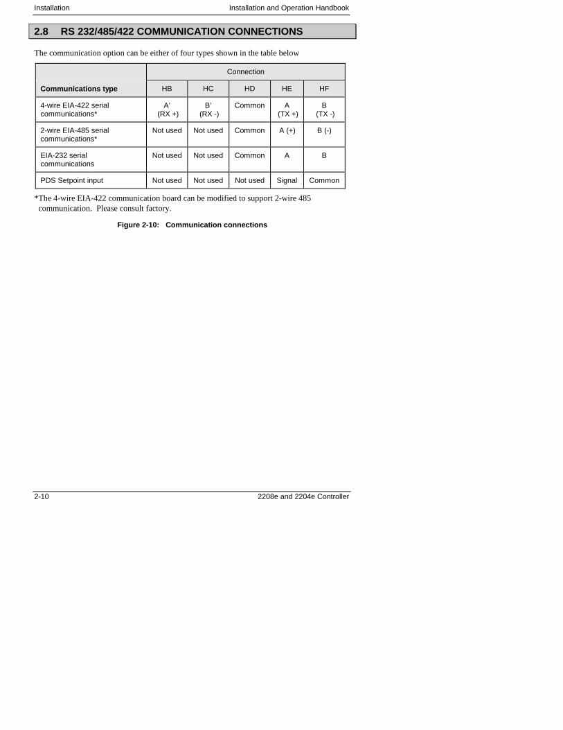
2.8 RS 232/485/422 COMMUNICATION CONNECTIONS
The communication option can be either of four types shown in the table below
Connection
Communications type HB HC HD HE HF
4-wire EIA-422 serialcommunications*
A’ (RX +)
B’ (RX -)
Common A (TX +)
B (TX -)
2-wire EIA-485 serialcommunications*
Not used Not used Common A (+) B (-)
EIA-232 serialcommunications
Not used Not used Common A B
PDS Setpoint input Not used Not used Not used Signal Common
*The 4-wire EIA-422 communication board can be modified to support 2-wire 485communication. Please consult factory.
Figure 2-10: Communication connections
Installation and Operation Handbook Installation
2208e and 2204e Controller 2-11
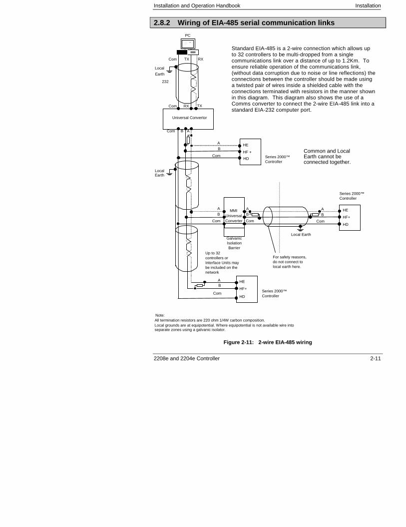
2.8.2 Wiring of EIA-485 serial communication links
Local
LocalEarth
HF +Series 2000™Controller
Com
Note:All termination resistors are 220 ohm 1/4W carbon composition.Local grounds are at equipotential. Where equipotential is not available wire intoseparate zones using a galvanic isolator.
A
B
PC
Universal Convertor
RXTXCom
Com TXRX
Up to 32controllers orInterface Units maybe included on thenetwork
232
Com B A
Com
A
B
GalvanicIsolationBarrier
Com
A
B
Com
AB
Local Earth
Com
AB
Earth
UniversalConverter
MMI
Series 2000™Controller
Series 2000™Controller
For safety reasons,do not connect tolocal earth here.
HD
HF+
HE
HD
HF+
HE
HE
HD
Figure 2-11: 2-wire EIA-485 wiring
Standard EIA-485 is a 2-wire connection which allows upto 32 controllers to be multi-dropped from a singlecommunications link over a distance of up to 1.2Km. Toensure reliable operation of the communications link,(without data corruption due to noise or line reflections) theconnections between the controller should be made usinga twisted pair of wires inside a shielded cable with theconnections terminated with resistors in the manner shownin this diagram. This diagram also shows the use of aComms converter to connect the 2-wire EIA-485 link into astandard EIA-232 computer port.
Common and LocalEarth cannot beconnected together.
Installation Installation and Operation Handbook
2-12 2208e and 2204e Controller
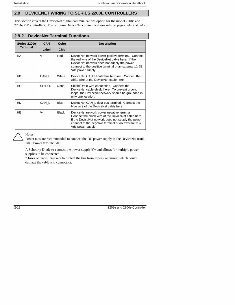
2.9 DEVICENET WIRING TO SERIES 2200E CONTROLLERS
This section covers the DeviceNet digital communications option for the model 2208e and2204e PID controllers. To configure DeviceNet communications refer to pages 5-16 and 5-17.
2.9.2 DeviceNet Terminal Functions
Series 2200eTerminal
CAN
Label
Color
Chip
Description
HA V+ Red DeviceNet network power positive terminal. Connectthe red wire of the DeviceNet cable here. If theDeviceNet network does not supply the power,connect to the positive terminal of an external 11-25Vdc power supply.
HB CAN_H White DeviceNet CAN_H data bus terminal. Connect thewhite wire of the DeviceNet cable here.
HC SHIELD None Shield/Drain wire connection. Connect theDeviceNet cable shield here. To prevent groundloops, the DeviceNet network should be grounded inonly one location.
HD CAN_L Blue DeviceNet CAN_L data bus terminal. Connect theblue wire of the DeviceNet cable here.
HE V- Black DeviceNet network power negative terminal.Connect the black wire of the DeviceNet cable here.If the DeviceNet network does not supply the power,connect to the negative terminal of an external 11-25Vdc power supply.
Notes:Power taps are recommended to connect the DC power supply to the DeviceNet trunkline. Power taps include:
A Schottky Diode to connect the power supply V+ and allows for multiple powersupplies to be connected.2 fuses or circuit breakers to protect the bus from excessive current which coulddamage the cable and connectors.
!
Installation and Operation Handbook Installation
2208e and 2204e Controller 2-13
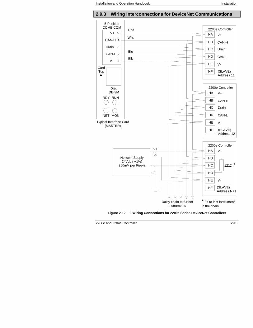
2.9.3 Wiring Interconnections for DeviceNet Communications
Figure 2-12: 2-Wiring Connections for 2200e Series DeviceNet Controllers
HA
HB
HC
HD
HE
HF
2200e Controller
(SLAVE)Address 11
V+
CAN-H
CAN-L
Drain
V-
HA
HB
HC
HD
HE
HF
2200e Controller
(SLAVE)Address 12
V+
CAN-H
CAN-L
Drain
V-
HA
HB
HC
HD
HE
HF
2200e Controller
(SLAVE)Address N+1
V+ 5
CAN-H 4
CAN-L 2
Drain 3
V- 1
5-PositionCOMBICOM
DiagDB-9M
RDY RUN
NET MON
CardTop
Red
Wht
Blu
Blk
121� *
* Fit to last instrumentin the chain
Network Supply24Vdc ( +1%)
250mV p-p Ripple
V+
V-
V-
V+
Typical Interface Card(MASTER)
Daisy chain to furtherinstruments

Installation Installation and Operation Handbook
2-14 2208e and 2204e Controller
Installation and Operation Handbook Access Levels
2208e and 2204e Controller 3-1
3 Chapter 3 ACCESS LEVELS
3 Chapter 3 ACCESS LEVELS..............................................1
3.2 THE DIFFERENT ACCESS LEVELS................................................. 2
3.3 SELECTING AN ACCESS LEVEL..................................................... 33.3.2 Returning to Operator Level....................................................................5
3.4 Edit level ............................................................................................ 53.4.2 Hiding or revealing a complete list ..........................................................63.4.3 Promoting a parameter ...........................................................................6
Access Levels Installation and Operation Handbook
3-2 2208e and 2204e Controller
3.2 THE DIFFERENT ACCESS LEVELS
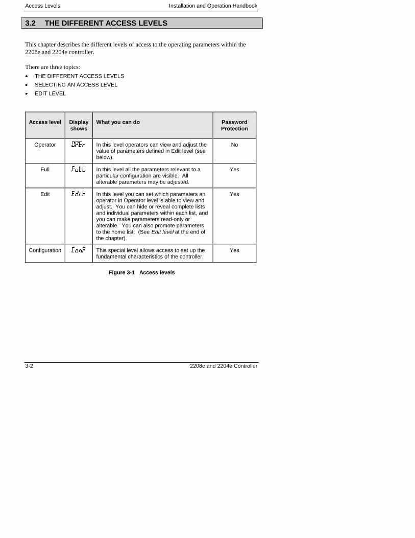
This chapter describes the different levels of access to the operating parameters within the2208e and 2204e controller.
There are three topics:
� THE DIFFERENT ACCESS LEVELS
� SELECTING AN ACCESS LEVEL
� EDIT LEVEL
Access level Displayshows
What you can do PasswordProtection
Operator ���� In this level operators can view and adjust thevalue of parameters defined in Edit level (seebelow).
No
Full ���� In this level all the parameters relevant to aparticular configuration are visible. Allalterable parameters may be adjusted.
Yes
Edit �� In this level you can set which parameters anoperator in Operator level is able to view andadjust. You can hide or reveal complete listsand individual parameters within each list, andyou can make parameters read-only oralterable. You can also promote parametersto the home list. (See Edit level at the end ofthe chapter).
Yes
Configuration �� � This special level allows access to set up thefundamental characteristics of the controller.
Yes
Figure 3-1 Access levels
Installation and Operation Handbook Access Levels
2208e and 2204e Controller 3-3
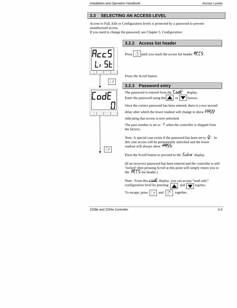
3.3 SELECTING AN ACCESS LEVEL
Access to Full, Edit or Configuration levels is protected by a password to preventunauthorised access.If you need to change the password, see Chapter 5, Configuration
����
����
3.2.2 Access list header
Press until you reach the access list header ‘����’.
Press the Scroll button
3.2.3 Password entry
The password is entered from the ‘����� display.
Enter the password using the or buttons.
Once the correct password has been entered, there is a two second
delay after which the lower readout will change to show ‘�����
indicating that access is now unlocked.
The pass number is set to ‘’ when the controller is shipped fromthe factory.
Note; A special case exists if the password has been set to ‘’. Inthis case access will be permanently unlocked and the lowerreadout will always show ‘����’
Press the Scroll button to proceed to the ‘����’ display.
(If an incorrect password has been entered and the controller is still‘locked’ then pressing Scroll at this point will simply return you tothe ���� list header.)
Note: From this ���� display, you can access “read only”configuration level by pressing and together.
To escape, press and together.
��
�
Access Levels Installation and Operation Handbook
3-4 2208e and 2204e Controller
.
.
��������
��� ����
�������
����
���
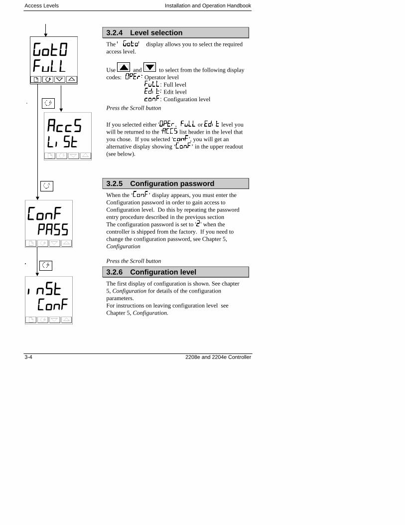
3.2.4 Level selection
The ������ display allows you to select the requiredaccess level.
Use and to select from the following displaycodes: ����� Operator level
����: Full level����� Edit level����: Configuration level
Press the Scroll button
If you selected either ‘����, ���� or ���� level youwill be returned to the ‘���� list header in the level thatyou chose. If you selected ‘����’, you will get analternative display showing ‘����’ in the upper readout(see below).
3.2.5 Configuration password
When the ‘����’ display appears, you must enter theConfiguration password in order to gain access toConfiguration level. Do this by repeating the passwordentry procedure described in the previous sectionThe configuration password is set to ‘�’ when thecontroller is shipped from the factory. If you need tochange the configuration password, see Chapter 5,Configuration
Press the Scroll button
3.2.6 Configuration level
The first display of configuration is shown. See chapter5, Configuration for details of the configurationparameters.For instructions on leaving configuration level seeChapter 5, Configuration.
Installation and Operation Handbook Access Levels
2208e and 2204e Controller 3-5
3.3.2 Returning to Operator Level
To return to operator level from either ‘����’ or ‘����’ level, repeat entry of the passwordand select ‘����’ on the ’����’ display.In ‘Edit’ level the controller will automatically return to operator level if no button is pressedfor 45 seconds.
3.4 EDIT LEVEL
Edit level is used to set which parameters you can see and adjust in Operator level. It alsogives access to the ‘Promote’ feature which allows you to select and add (‘Promote’) up totwelve parameters into the Home display list, thereby giving simple access to commonly usedparameters.
Setting operator access to a parameter
First you must select ���� level, as shown on the previous page.Once in ���� level you select a list or a parameter within a list in the same way as you wouldin Operator or Full level� �hat is, you move from list header to list header by pressing thePage button, and from parameter to parameter within each list using the Scroll button.However, in Edit level what is displayed is not the value of a selected parameter but a coderepresenting the parameter’s availability in Operator level.
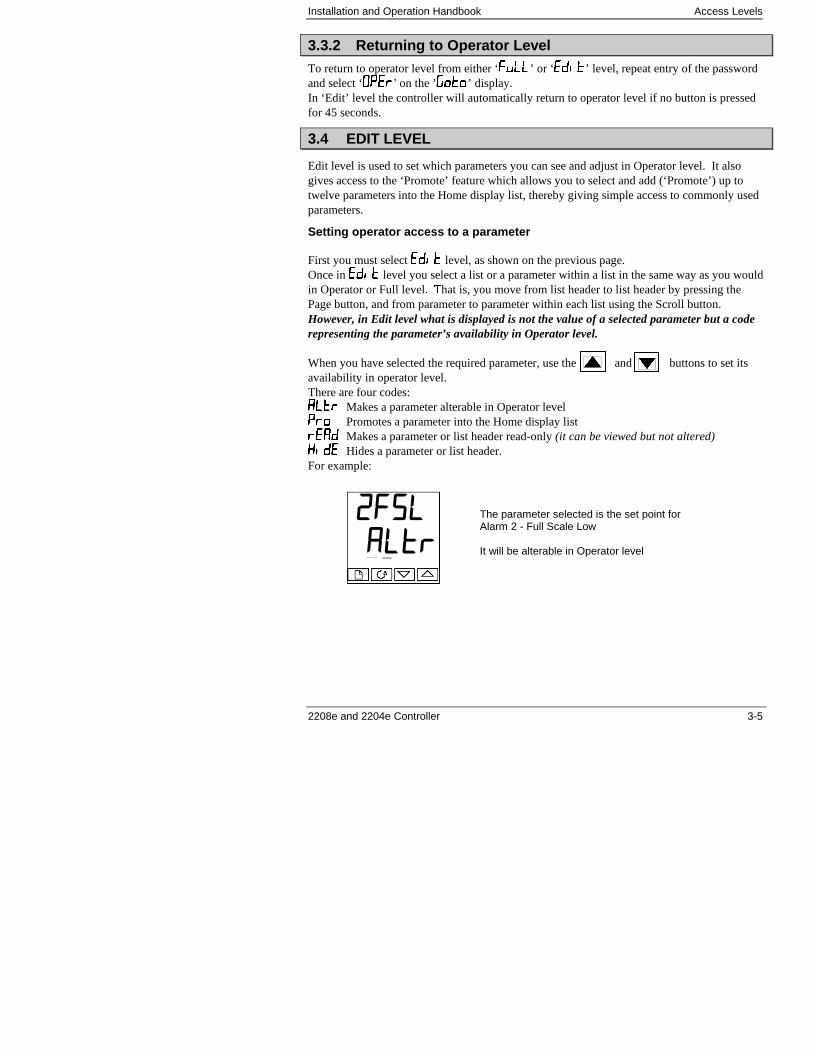
When you have selected the required parameter, use the and buttons to set itsavailability in operator level.There are four codes:�������� Makes a parameter alterable in Operator level������ Promotes a parameter into the Home display list�������� Makes a parameter or list header read-only (it can be viewed but not altered)�������� Hides a parameter or list header.For example:
The parameter selected is the set point forAlarm 2 - Full Scale Low
It will be alterable in Operator level
� ��
����
Access Levels Installation and Operation Handbook
3-6 2208e and 2204e Controller
3.4.2 Hiding or revealing a complete list
To hide a complete list of parameters, all you have to do is hide the list header. If a list headeris selected only two selections are available: ���� and ����.(It is not possible to hide the ‘����’ list which will always display the code: ‘����’.)
3.4.3 Promoting a parameter
Scroll through the lists to the required parameter and choose the ‘���’ code. The parameter isthen automatically added (promoted) into the Home display list (the parameter will also beaccessible as normal from the standard lists. a maximum of 12 parameters can be promoted.Promoted parameters are automatically ‘alterable’.
Installation and Operation Handbook Tuning
2208e and 2204e Controller 4-1
4. Chapter 4 TUNING
4. Chapter 4 TUNING.............................................................1
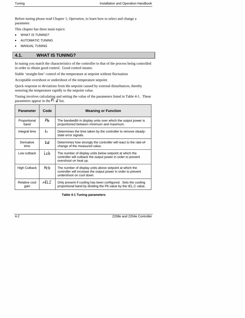
4.1. WHAT IS TUNING?............................................................................ 2
4.2. AUTOMATIC TUNING ....................................................................... 34.2.1. Heating and Cooling Output Cycle Times...............................................3
4.3. How to Tune ...................................................................................... 44.3.1. Typical automatic tuning cycle ................................................................54.3.2. Calculation of the cutback values ...........................................................5
4.4. MANUAL TUNING.............................................................................. 64.4.1. Setting the cutback values......................................................................74.4.2. Integrating action and manual reset .......................................................84.4.3. Automatic droop compensation (Adc).....................................................8
Tuning Installation and Operation Handbook
4-2 2208e and 2204e Controller
Before tuning please read Chapter 1, Operation, to learn how to select and change aparameter.
This chapter has three main topics:
� WHAT IS TUNING?
� AUTOMATIC TUNING
� MANUAL TUNING
4.1. WHAT IS TUNING?
In tuning you match the characteristics of the controller to that of the process being controlledin order to obtain good control. Good control means:
Stable ‘straight-line’ control of the temperature at setpoint without fluctuation
Acceptable overshoot or undershoot of the temperature setpoint
Quick response to deviations from the setpoint caused by external disturbances, therebyrestoring the temperature rapidly to the setpoint value.
Tuning involves calculating and setting the value of the parameters listed in Table 4-1. Theseparameters appear in the ��� list.
Parameter Code Meaning or Function
Proportionalband
�� The bandwidth in display units over which the output power isproportioned between minimum and maximum.
Integral time �� Determines the time taken by the controller to remove steady-state error signals.
Derivativetime
�� Determines how strongly the controller will react to the rate-of-change of the measured value.
Low cutback ��� The number of display units below setpoint at which thecontroller will cutback the output power in order to preventovershoot on heat up.
High Cutback ��� The number of display units above setpoint at which thecontroller will increase the output power in order to preventundershoot on cool down.
Relative coolgain
��� Only present if cooling has been configured. Sets the coolingproportional band by dividing the Pb value by the rEL.C value.
Table 4-1 Tuning parameters
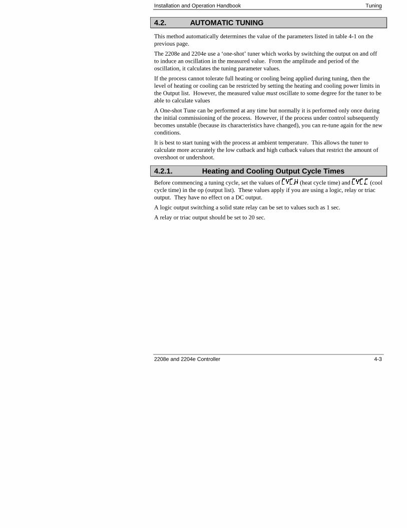
Installation and Operation Handbook Tuning
2208e and 2204e Controller 4-3
4.2. AUTOMATIC TUNING
This method automatically determines the value of the parameters listed in table 4-1 on theprevious page.
The 2208e and 2204e use a ‘one-shot’ tuner which works by switching the output on and offto induce an oscillation in the measured value. From the amplitude and period of theoscillation, it calculates the tuning parameter values.
If the process cannot tolerate full heating or cooling being applied during tuning, then thelevel of heating or cooling can be restricted by setting the heating and cooling power limits inthe Output list. However, the measured value must oscillate to some degree for the tuner to beable to calculate values
A One-shot Tune can be performed at any time but normally it is performed only once duringthe initial commissioning of the process. However, if the process under control subsequentlybecomes unstable (because its characteristics have changed), you can re-tune again for the newconditions.
It is best to start tuning with the process at ambient temperature. This allows the tuner tocalculate more accurately the low cutback and high cutback values that restrict the amount ofovershoot or undershoot.
4.2.1. Heating and Cooling Output Cycle Times
Before commencing a tuning cycle, set the values of ����� (heat cycle time) and ����� (coolcycle time) in the op (output list). These values apply if you are using a logic, relay or triacoutput. They have no effect on a DC output.
A logic output switching a solid state relay can be set to values such as 1 sec.
A relay or triac output should be set to 20 sec.
Tuning Installation and Operation Handbook
4-4 2208e and 2204e Controller
4.3. HOW TO TUNE
1. Set the setpoint to the value at which you will normally operate the process.
2. In the ‘��’ list, select ‘��’ and set it to ‘ �’
3. Press the Page and Scroll buttons together to return to the Home display. The displaywill flash ‘��’ to indicate that tuning is in progress.
4. The controller will induce an oscillation in the temperature by turning the heating on andthen off. The first cycle will not complete until the measured value has reached therequired setpoint.
5. After two cycles of oscillation the tuning will be completed and the tuner will switchitself off.
6. The controller will then calculate the tuning parameters listed in Table 4-1 and willresume normal control action.
If you want ‘Proportional only’ or ‘PD’ or ‘PI’ control, you should set the ‘�’ or ‘�’parameters to��� before commencing the tuning cycle. The tuner will leave them off andwill not calculate a value for them.
For valve position tuning and set-up, please refer to Appendix D.
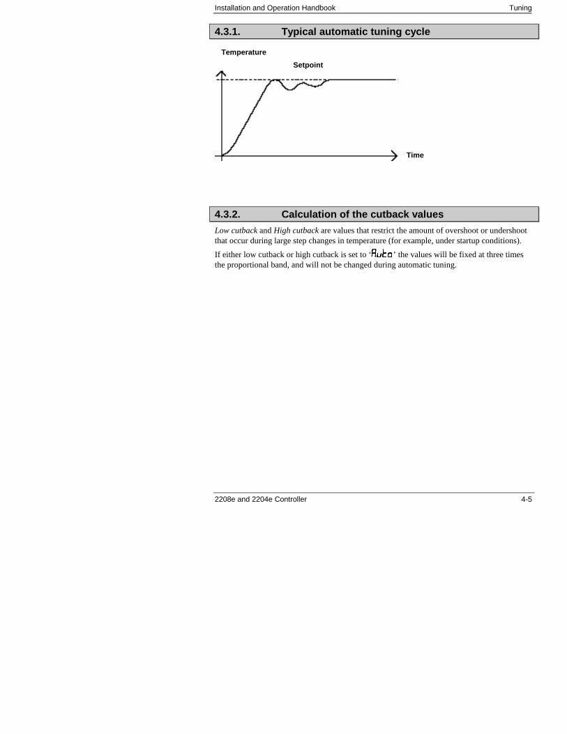
Installation and Operation Handbook Tuning
2208e and 2204e Controller 4-5
4.3.1. Typical automatic tuning cycle
4.3.2. Calculation of the cutback values
Low cutback and High cutback are values that restrict the amount of overshoot or undershootthat occur during large step changes in temperature (for example, under startup conditions).
If either low cutback or high cutback is set to ‘� ’ the values will be fixed at three timesthe proportional band, and will not be changed during automatic tuning.
Time
Setpoint
Temperature
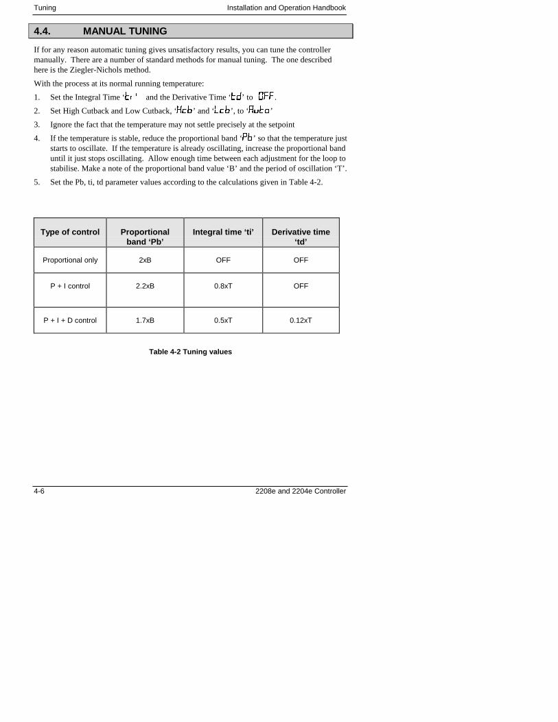
Tuning Installation and Operation Handbook
4-6 2208e and 2204e Controller
4.4. MANUAL TUNING
If for any reason automatic tuning gives unsatisfactory results, you can tune the controllermanually. There are a number of standard methods for manual tuning. The one describedhere is the Ziegler-Nichols method.
With the process at its normal running temperature:
1. Set the Integral Time ‘�� and the Derivative Time ‘�’ to ���.
2. Set High Cutback and Low Cutback, ‘���’ and ‘���’, to ‘� ’
3. Ignore the fact that the temperature may not settle precisely at the setpoint
4. If the temperature is stable, reduce the proportional band ‘��’ so that the temperature juststarts to oscillate. If the temperature is already oscillating, increase the proportional banduntil it just stops oscillating. Allow enough time between each adjustment for the loop tostabilise. Make a note of the proportional band value ‘B’ and the period of oscillation ‘T’.
5. Set the Pb, ti, td parameter values according to the calculations given in Table 4-2.
Type of control Proportionalband ‘Pb’
Integral time ‘ti’ Derivative time‘td’
Proportional only 2xB OFF OFF
P + I control 2.2xB 0.8xT OFF
P + I + D control 1.7xB 0.5xT 0.12xT
Table 4-2 Tuning values
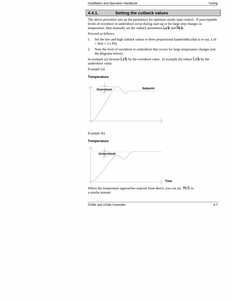
Installation and Operation Handbook Tuning
2208e and 2204e Controller 4-7
4.4.1. Setting the cutback values
The above procedure sets up the parameters for optimum steady state control. If unacceptablelevels of overshoot or undershoot occur during start-up or for large step changes intemperature, then manually set the cutback parameters ��� and ���.
Proceed as follows:
1. Set the low and high cutback values to three proportional bandwidths (that is to say, Lcb= Hcb = 3 x Pb).
2. Note the level of overshoot or undershoot that occurs for large temperature changes (seethe diagrams below).
In example (a) increase ��� by the overshoot value. In example (b) reduce ��� by theundershoot value.
Example (a)
Temperature
Example (b)
Temperature
Where the temperature approaches setpoint from above, you can set��� ina similar manner.
Time
Undershoot
SetpointOvershoot
Tuning Installation and Operation Handbook
4-8 2208e and 2204e Controller
4.4.2. Integrating action and manual reset
In a full three-term controller (that is, a PID controller), the integral term ‘ti’ automaticallyremoves steady state errors from the setpoint. If the controller is set up to work in two-termmode (that is, PD mode), the integral term will be set to ���. Under these conditions themeasured value may not settle precisely at setpoint. When the integral term is set to OFF theparameter manual reset (code ���) appears in the ��� ���� in ‘���’ Access level.This parameter represents the value of the power output that will be delivered when the erroris zero. You may set this value manually in order to remove the steady state error.
4.4.3. Automatic droop compensation (Adc)
The steady state error from the setpoint, which occurs when the integral term is set to OFF, issometimes referred to as ‘droop’. ��� automatically calculates the manual reset value inorder to remove this droop. To use this facility, you must first allow the temperature tostabilise. Then, in the autotune parameter list, you must set ��� to ‘����’. The controllerwill then calculate a new value for manual reset, and switch ��� to ‘���’.
��� can be repeated as often as you require but between each adjustment you must allow timefor the temperature to stabilise.
Installation and Operation Handbook Configuration
2208e and 2204e Controller 5-1
5 CHAPTER 5 CONFIGURATIONPAGE
Selecting Configuration Level ................................................... 5-2
Leaving Configuration ............................................................... 5-3
Steps Involved in Configuring a Controller ................................ 5-3
Navigation Diagram .................................................................. 5-4
Configuration Parameter Tables ............................................... 5-6
Configuration of Digital Communications ………………… 5-16
WARNINGConfiguration is protected and should only be carried out by an authorisedperson. Incorrect configuration could result in damage to the process beingcontrolled and/or personal injury. It is the responsibility of the personcommissioning the instrument to ensure that the configuration is correct.
Whenever the configuration menus are displayed or accessed all controller outputsare held at the power off state and control operstion is suspended until exiting fromconfiguration.
!
!
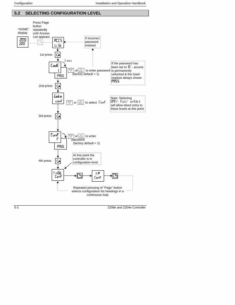
Configuration Installation and Operation Handbook
5-2 2208e and 2204e Controller
5.2 SELECTING CONFIGURATION LEVEL
��������
At this point thecontroller is inconfiguration level
��������
“HOME”display
Press Pagebuttonrepeatedlyuntil AccessList appears
��������
��������
����������
��
� ��� ��
or to enter password (factory default = 1)
If incorrectpasswordentered
or to enterpassword (factory default = 2)
Note: Selecting����������or �� �will allow direct entry tothese levels at this point
1st press
2nd press
3rd press
If the password hasbeen set to ‘�’ - accessis permanentlyunlocked & the lowerreadout always shows��
Repeated pressing of “Page” buttonselects configuration list headings in a
continuous loop
2 secs
or to select �����
�� ��
��
������
4th press
����������������
������������
Installation and Operation Handbook Configuration
2208e and 2204e Controller 5-3
Figure 5.1
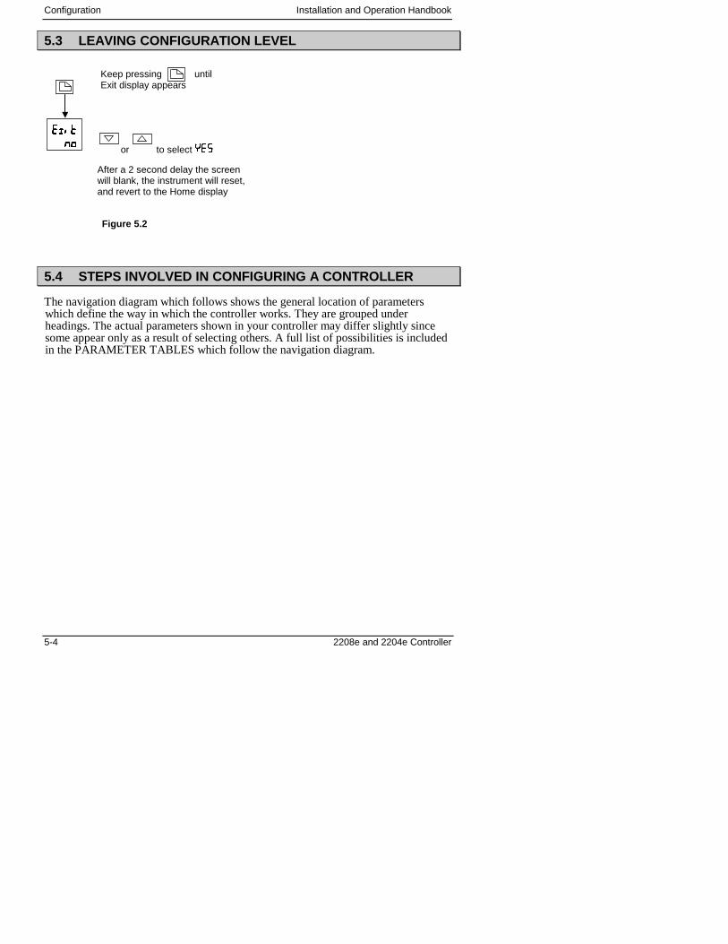
Configuration Installation and Operation Handbook
5-4 2208e and 2204e Controller
5.3 LEAVING CONFIGURATION LEVEL
5.4 STEPS INVOLVED IN CONFIGURING A CONTROLLER
The navigation diagram which follows shows the general location of parameterswhich define the way in which the controller works. They are grouped underheadings. The actual parameters shown in your controller may differ slightly sincesome appear only as a result of selecting others. A full list of possibilities is includedin the PARAMETER TABLES which follow the navigation diagram.
or to select �
��� ���
����
Keep pressing untilExit display appears
After a 2 second delay the screenwill blank, the instrument will reset,and revert to the Home display
Figure 5.2
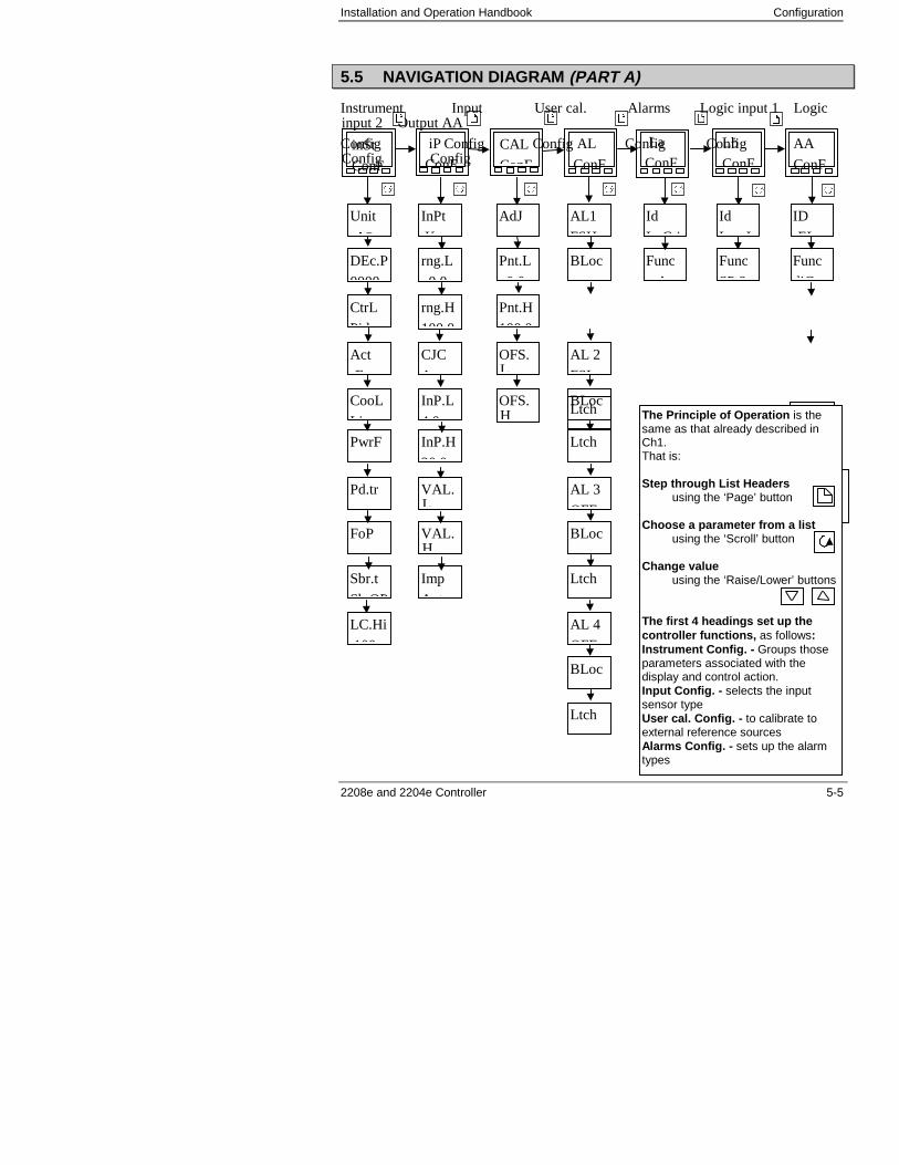
Installation and Operation Handbook Configuration
2208e and 2204e Controller 5-5
5.5 NAVIGATION DIAGRAM (PART A)
Instrument Input User cal. Alarms Logic input 1 Logicinput 2 Output AA
Config Config Config Config ConfigConfig Config
Ltch
Unit
�C
inSt
ConF
Seeparametertables
iP
ConF CAL
ConF
AL
ConF
Lb
ConF AA
ConF
DEc.P
0000
CtrL
Pid
Act
E
CooL
Li
InPt
K t
rng.L
0 0
AdJ
Pnt.L
0 0
Pnt.H
100 0
OFS.L
AL1
FSH
OFS.H
Id
L G i
Func
A
Id
L I
Func
SP 2
ID
EL
Sens
norPwrF
Pd.tr
FoP
InP.L
4 0
InP.H
20 0
VAL.L
VAL.H
CJC
A t
BLoc
AL 2
FSL
Ltch
BLoc
AL 3
OFF
Ltch
BLoc
AL 4
OFF
Ltch
BLoc
The Principle of Operation is thesame as that already described inCh1.That is:
Step through List Headers using the ‘Page’ button
Choose a parameter from a list using the ‘Scroll’ button
Change value using the ‘Raise/Lower’ buttons
The first 4 headings set up thecontroller functions, as follows:Instrument Config. - Groups thoseparameters associated with thedisplay and control action.Input Config. - selects the inputsensor typeUser cal. Config. - to calibrate toexternal reference sourcesAlarms Config. - sets up the alarmtypes
Imp
A t
Func
diG
Sbr.t
Sb OP
La
ConF
rng.H
100 0
LC.Hi
100

Configuration Installation and Operation Handbook
5-6 2208e and 2204e Controller
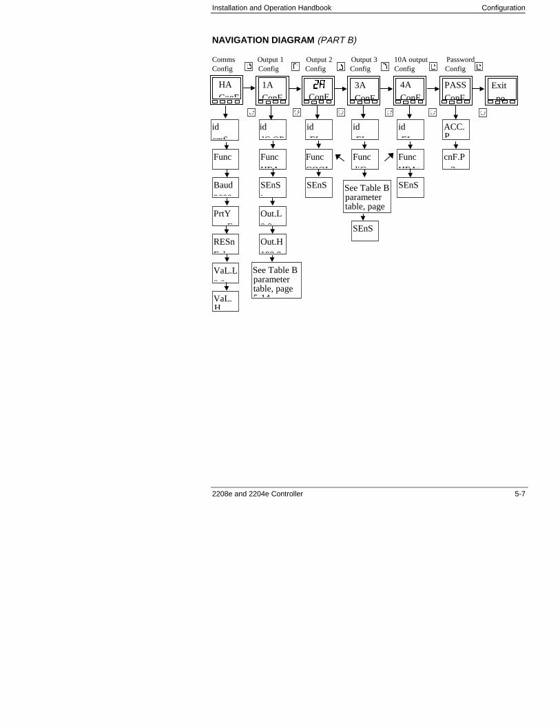
Installation and Operation Handbook Configuration
2208e and 2204e Controller 5-7
NAVIGATION DIAGRAM (PART B)
Comms Output 1 Output 2 Output 3 10A output PasswordConfig Config Config Config Config Config
id
cmS
HA
ConF
See Table Bparametertable, page5 14
See Table Bparametertable, page
1A
ConF ��ConF
3A
ConF
Exit
no
4A
ConF
PASS
ConF
id
dC OP
id
EL
id
EL
id
EL
ACC.P
Func Func
diG
SEnS
Func
HEA
Func
COOL
Baud
9600
SEnS
i
SEnS
Func
HEAt
cnF.P
2
SEnS
PrtY
E
Out.L
0 0
RESn
F l
Out.H
100 0
VaL.L
0 0
VaL.H

Configuration Installation and Operation Handbook
5-8 2208e and 2204e Controller
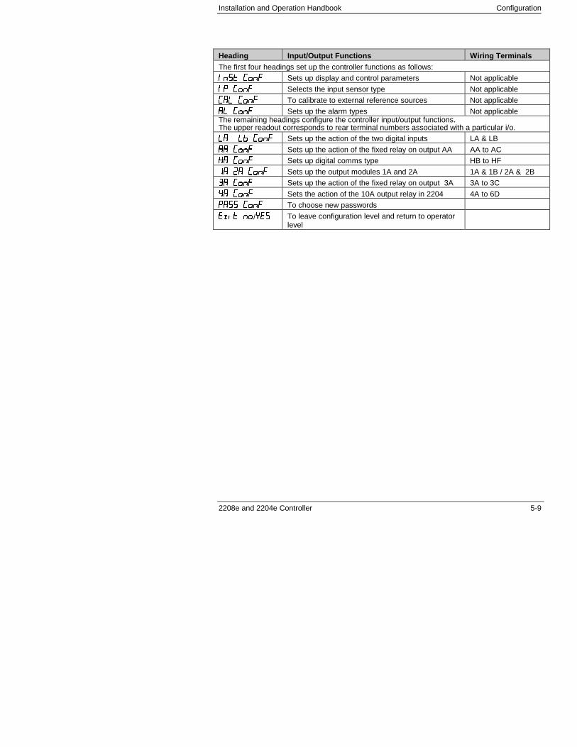
Installation and Operation Handbook Configuration
2208e and 2204e Controller 5-9
Heading Input/Output Functions Wiring TerminalsThe first four headings set up the controller functions as follows:
��� ��� Sets up display and control parameters Not applicable
�� ��� Selects the input sensor type Not applicable
�� ��� To calibrate to external reference sources Not applicable
�� ��� Sets up the alarm types Not applicableThe remaining headings configure the controller input/output functions.The upper readout corresponds to rear terminal numbers associated with a particular i/o.
�� �� ��� Sets up the action of the two digital inputs LA & LB
�� ��� Sets up the action of the fixed relay on output AA AA to AC
�� ��� Sets up digital comms type HB to HF
�� �� ��� Sets up the output modules 1A and 2A 1A & 1B / 2A & 2B
�� ��� Sets up the action of the fixed relay on output 3A 3A to 3C
�� ��� Sets the action of the 10A output relay in 2204 4A to 6D
���� ��� To choose new passwords
��� ��/��� To leave configuration level and return to operatorlevel
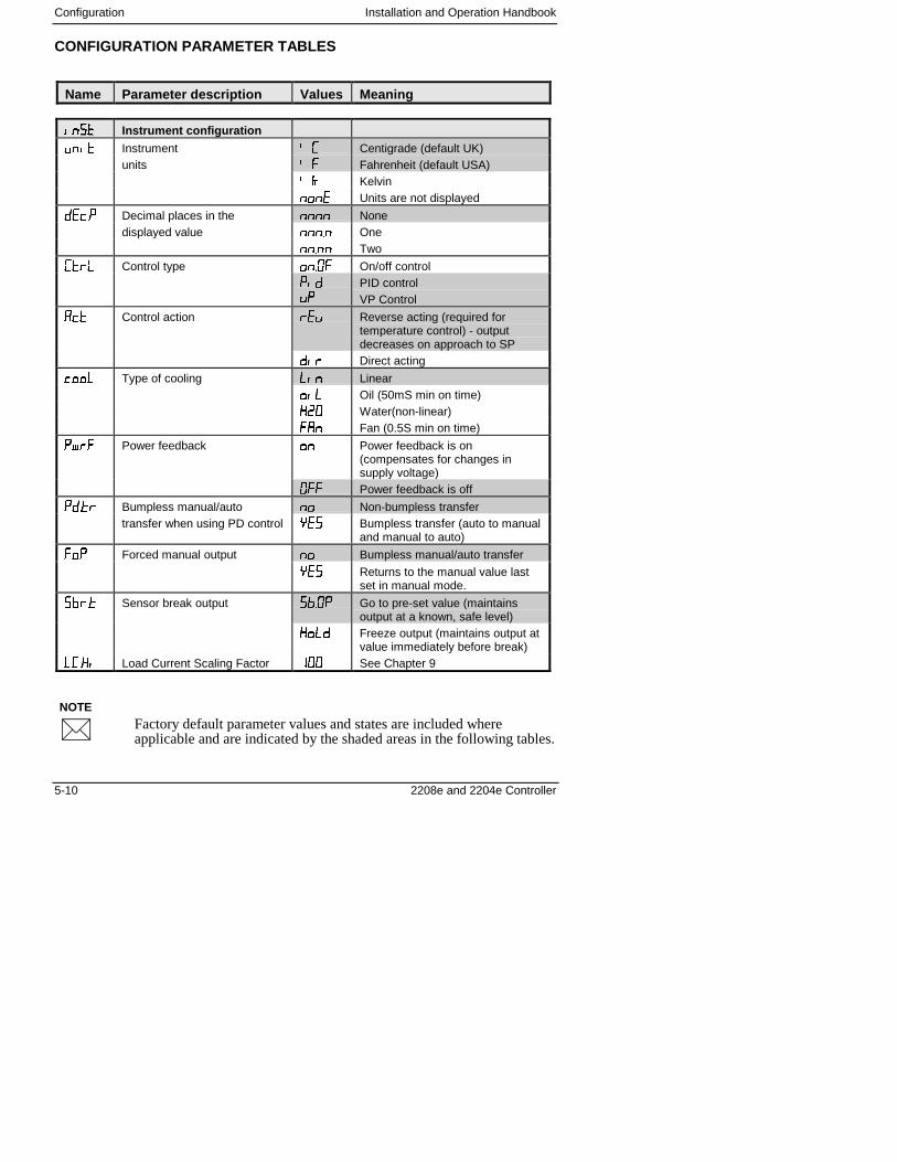
Configuration Installation and Operation Handbook
5-10 2208e and 2204e Controller
NOTE
�
CONFIGURATION PARAMETER TABLES
Name Parameter description Values Meaning
������ Instrument configuration
���� Instrument � Centigrade (default UK)units �� Fahrenheit (default USA)
� Kelvin
��� Units are not displayed
� !�� Decimal places in the ���� Nonedisplayed value ����� One
����� Two
�"� Control type ���#� On/off control
���
$%
PID controlVP Control
�!� Control action " $ Reverse acting (required fortemperature control) - outputdecreases on approach to SP
��" Direct acting
!��� Type of cooling ��� Linear
��� Oil (50mS min on time)
��# Water(non-linear)
��� Fan (0.5S min on time)
�&"� Power feedback �� Power feedback is on(compensates for changes insupply voltage)
#�� Power feedback is off
����" Bumpless manual/auto �� Non-bumpless transfertransfer when using PD control � Bumpless transfer (auto to manual
and manual to auto)
��� Forced manual output �� Bumpless manual/auto transfer
��� Returns to the manual value lastset in manual mode.
'"�� Sensor break output '�#� Go to pre-set value (maintainsoutput at a known, safe level)
���� Freeze output (maintains output atvalue immediately before break)
���� Load Current Scaling Factor ��� See Chapter 9
Factory default parameter values and states are included whereapplicable and are indicated by the shaded areas in the following tables.
Installation and Operation Handbook Configuration
2208e and 2204e Controller 5-11
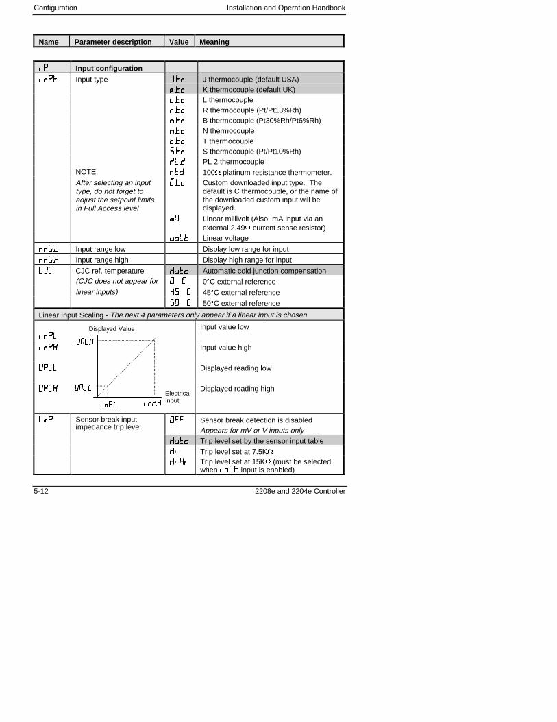
Configuration Installation and Operation Handbook
5-12 2208e and 2204e Controller
Name Parameter description Value Meaning
���� Input configuration
���� Input type (��! J thermocouple (default USA)
)��! K thermocouple (default UK)
���! L thermocouple
"��! R thermocouple (Pt/Pt13%Rh)
'��! B thermocouple (Pt30%Rh/Pt6%Rh)
���! N thermocouple
���! T thermocouple
��! S thermocouple (Pt/Pt10%Rh)
���� PL 2 thermocoupleNOTE: "�� 100� platinum resistance thermometer.After selecting an inputtype, do not forget toadjust the setpoint limitsin Full Access level
��! Custom downloaded input type. Thedefault is C thermocouple, or the name ofthe downloaded custom input will bedisplayed.
*+ Linear millivolt (Also mA input via anexternal 2.49� current sense resistor)
$��� Linear voltage
"�,�� Input range low Display low range for input
"�,�� Input range high Display high range for input
( CJC ref. temperature ���� Automatic cold junction compensation(CJC does not appear for �� 0�C external referencelinear inputs) �-� 45�C external reference
-�� 50�C external reference
Linear Input Scaling - The next 4 parameters only appear if a linear input is chosen
����
Input value low
���� Input value high
+��� Displayed reading low
+��� Displayed reading high
�*� Sensor break inputimpedance trip level
#�� Sensor break detection is disabledAppears for mV or V inputs only
���� Trip level set by the sensor input table
�� Trip level set at 7.5K�
���� Trip level set at 15K� (must be selectedwhen $��� input is enabled)
�����
�����
����� �����
Displayed Value
ElectricalInput
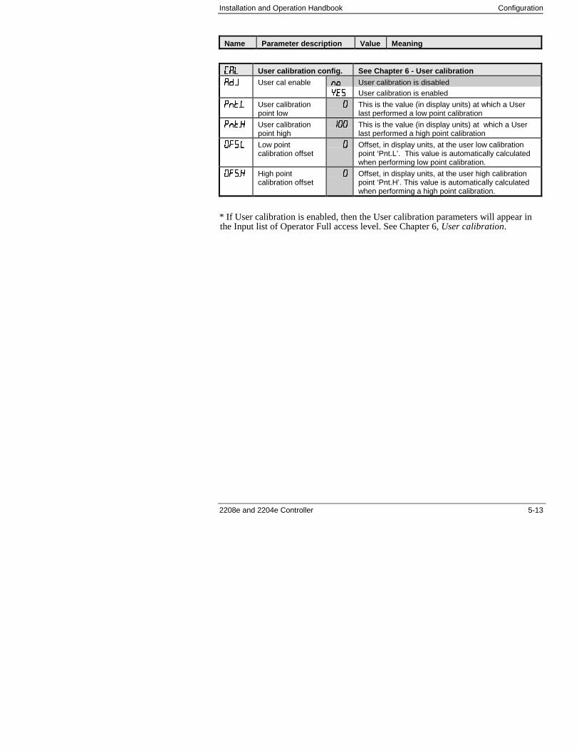
Installation and Operation Handbook Configuration
2208e and 2204e Controller 5-13
Name Parameter description Value Meaning
���� User calibration config. See Chapter 6 - User calibration
��( User cal enable �� User calibration is disabled
� User calibration is enabled
����� User calibrationpoint low
� This is the value (in display units) at which a Userlast performed a low point calibration
����� User calibrationpoint high
��� This is the value (in display units) at which a Userlast performed a high point calibration
#��� Low pointcalibration offset
� Offset, in display units, at the user low calibrationpoint ‘Pnt.L’. This value is automatically calculatedwhen performing low point calibration.
#��� High pointcalibration offset
� Offset, in display units, at the user high calibrationpoint ‘Pnt.H’. This value is automatically calculatedwhen performing a high point calibration.
* If User calibration is enabled, then the User calibration parameters will appear inthe Input list of Operator Full access level. See Chapter 6, User calibration.
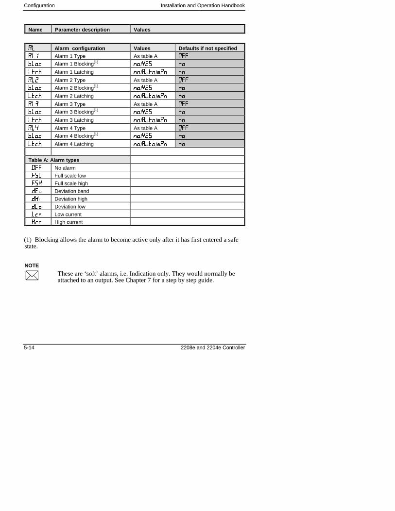
Configuration Installation and Operation Handbook
5-14 2208e and 2204e Controller
NOTE
�
Name Parameter description Values
���� Alarm configuration Values Defaults if not specified
��� Alarm 1 Type As table A #��
'��! Alarm 1 Blocking(1)��/� ��
��!. Alarm 1 Latching ��/����/*�� ��
��� Alarm 2 Type As table A #��
'��! Alarm 2 Blocking(1)��/� ��
��!. Alarm 2 Latching ��/����/*�� ��
��� Alarm 3 Type As table A #��
'��! Alarm 3 Blocking(1)��/� ��
��!. Alarm 3 Latching ��/����/*�� ��
��� Alarm 4 Type As table A #��
'��! Alarm 4 Blocking(1)��/� ��
��!. Alarm 4 Latching ��/����/*�� ��
Table A: Alarm types
#�� No alarm
�� Full scale low
�� Full scale high
� $ Deviation band
��� Deviation high
��� Deviation low
�!" Low current
�!" High current
(1) Blocking allows the alarm to become active only after it has first entered a safestate.
These are ‘soft’ alarms, i.e. Indication only. They would normally beattached to an output. See Chapter 7 for a step by step guide.
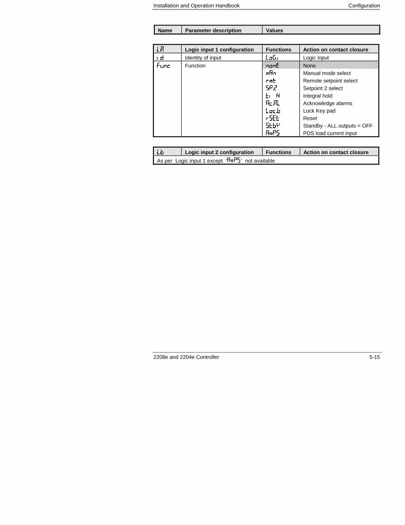
Installation and Operation Handbook Configuration
2208e and 2204e Controller 5-15
Name Parameter description Values
���� Logic input 1 configuration Functions Action on contact closure
�� Identity of input ����� Logic input
���! Function ��� None
*�� Manual mode select
"*� Remote setpoint select
��� Setpoint 2 select
�� � Integral hold
�!��� Acknowledge alarms
��!�' Lock Key pad
"��� Reset
�'� Standby - ALL outputs = OFF
�*� PDS load current input
�'�' Logic input 2 configuration Functions Action on contact closure
As per Logic input 1 except ‘�*�’ not available
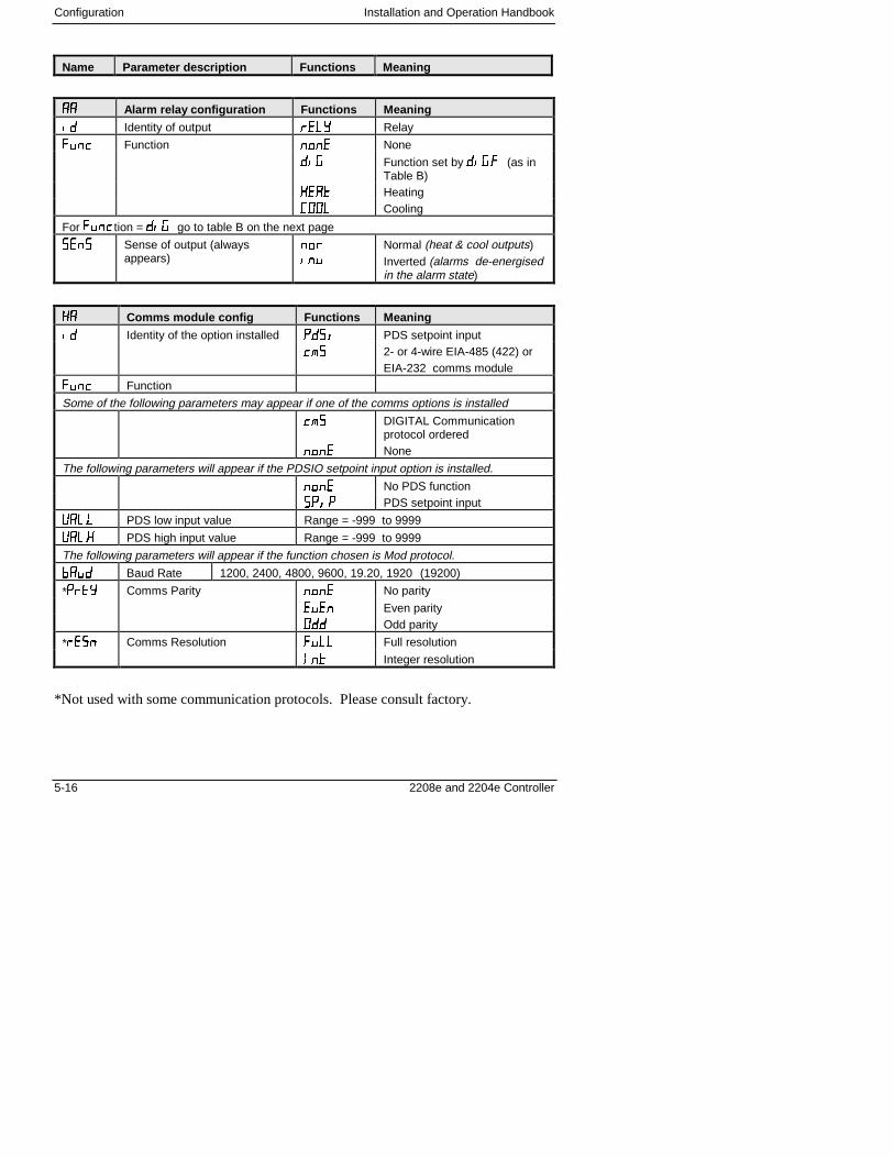
Configuration Installation and Operation Handbook
5-16 2208e and 2204e Controller
Name Parameter description Functions Meaning
���� Alarm relay configuration Functions Meaning
�� Identity of output " �/ Relay
���! Function ��� None
��� Function set by ����� (as inTable B)
� �� Heating
##� Cooling
For ���!tion = ��� go to table B on the next page
� Sense of output (alwaysappears)
��"
��$
Normal (heat & cool outputs)Inverted (alarms de-energisedin the alarm state)
���� Comms module config Functions Meaning
�� Identity of the option installed �0�� PDS setpoint input
!* 2- or 4-wire EIA-485 (422) orEIA-232 comms module
���! Function
Some of the following parameters may appear if one of the comms options is installed
!*� DIGITAL Communicationprotocol ordered
��� None
The following parameters will appear if the PDSIO setpoint input option is installed.
��� No PDS function
���� PDS setpoint input
+���� PDS low input value Range = -999 to 9999
+���� PDS high input value Range = -999 to 9999
The following parameters will appear if the function chosen is Mod protocol.
���� Baud Rate 1200, 2400, 4800, 9600, 19.20, 1920 (19200)
*�"�/ Comms Parity ��� No parity
$ � Even parity
#�� Odd parity
*" � Comms Resolution ���� Full resolution
��� Integer resolution
*Not used with some communication protocols. Please consult factory.
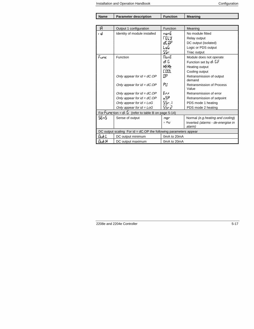
Installation and Operation Handbook Configuration
2208e and 2204e Controller 5-17
Name Parameter description Function Meaning
�� Output 1 configuration Function Meaning
�� Identity of module installed ��� No module fitted
1 �/ Relay output
��#� DC output (isolated)
��� Logic or PDS output
" Triac output
���! Function 2�� Module does not operate
0�� Function set by �����
� �� Heating output
##� Cooling outputOnly appear for id = dC.OP #� Retransmission of output
demandOnly appear for id = dC.OP �+ Retransmission of Process
ValueOnly appear for id = dC.OP "" Retransmission of errorOnly appear for id = dC.OP &� Retransmission of setpointOnly appear for id = LoG "�� PDS mode 1 heatingOnly appear for id = LoG "�� PDS mode 2 heating
For ���!tion = ��� (refer to table B on page 5-14)
� Sense of output ��"
��$
Normal (e.g.heating and cooling)Inverted (alarms - de-energise inalarm)
DC output scaling For id = dC.OP the following parameters appear
#���� DC output minimum 0mA to 20mA
#���� DC output maximum 0mA to 20mA
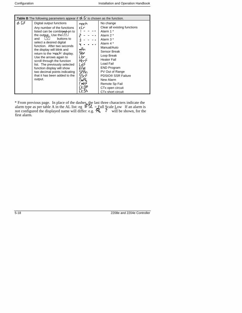
Configuration Installation and Operation Handbook
5-18 2208e and 2204e Controller
Table B The following parameters appear if ‘���’ is chosen as the function.
����� Digital output functions ��!. No changeAny number of the functionslisted can be combined on tothe output. Use the and buttons toselect a desired digitalfunction. After two secondsthe display will blink andreturn to the ‘��!.’ display.Use the arrows again toscroll through the functionlist. The previously selectedfunction display will showtwo decimal points indicatingthat it has been added to theoutput.
!�"� 3 3 3
*� 3 3 3 *� 3 3 3 *� 3 3 3 *4��'"�'"��"����� 2����"�2&��1*����#���.
Clear all existing functionsAlarm 1 *Alarm 2 *Alarm 3 *Alarm 4 *Manual/AutoSensor BreakLoop BreakHeater FailLoad FailEND ProgramPV Out of RangePDSIO® SSR FailureNew AlarmRemote Sp FailCTx open circuitCTx short circuit
* From previous page. In place of the dashes, the last three characters indicate thealarm type as per table A in the AL list: eg ���� = Full Scale Low If an alarm isnot configured the displayed name will differ: e.g. ‘�� �� will be shown, for thefirst alarm.
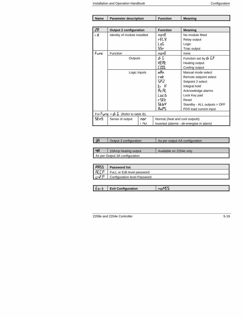
Installation and Operation Handbook Configuration
2208e and 2204e Controller 5-19
Name Parameter description Function Meaning
���� Output 2 configuration Function Meaning
�� Identity of module installed ��� No module fitted
" �/ Relay output
��� Logic
" Triac output
���! Function ��� none
Outputs ��� Function set by �����
� �� Heating output
##� Cooling output
Logic Inputs *�� Manual mode select
"*� Remote setpoint select
��� Setpoint 2 select
�� � Integral hold
�!��� Acknowledge alarms
��!�' Lock Key pad
"��� Reset
�'� Standby - ALL outputs = OFF
�*� PDS load current input
For ���! = ��� (Refer to table B).
� Sense of output ��"
��$
Normal (heat and cool outputs)Inverted (alarms - de-energise in alarm)
���� Output 3 configuration As per output AA configuration
���� 10Amp heating output Available on 2204e only.
As per Output 3A configuration
���� Password list
��� FuLL or Edit level password
!���� Configuration level Password
��� ��� Exit Configuration ����/� �
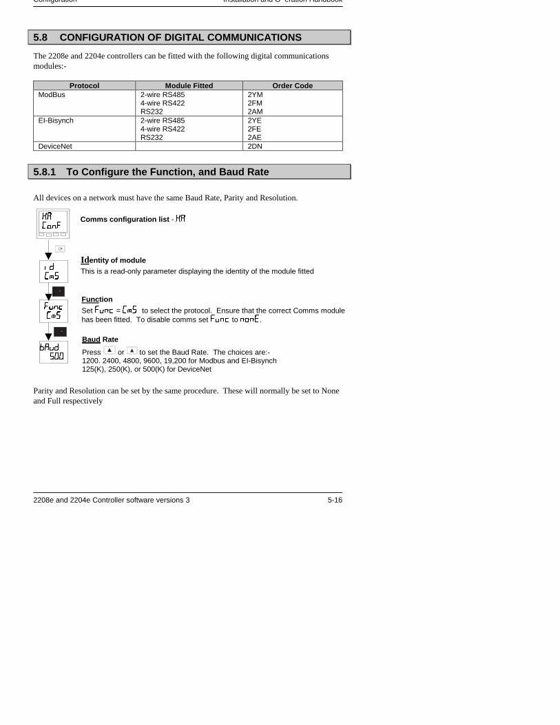
Configuration Installation and O eration Handbook
2208e and 2204e Controller software versions 3 5-16
5.8 CONFIGURATION OF DIGITAL COMMUNICATIONS
The 2208e and 2204e controllers can be fitted with the following digital communicationsmodules:-
Protocol Module Fitted Order CodeModBus 2-wire RS485
4-wire RS422RS232
2YM2FM2AM
EI-Bisynch 2-wire RS4854-wire RS422RS232
2YE2FE2AE
DeviceNet 2DN
5.8.1 To Configure the Function, and Baud Rate
All devices on a network must have the same Baud Rate, Parity and Resolution.
Parity and Resolution can be set by the same procedure. These will normally be set to Noneand Full respectively
Comms configuration list - ��
Identity of moduleThis is a read-only parameter displaying the identity of the module fitted
Function
Set ���� = �� to select the protocol. Ensure that the correct Comms modulehas been fitted. To disable comms set ���� to ����.
��
����
�
��
����
��
����
���
Baud Rate
Press or to set the Baud Rate. The choices are:-1200. 2400, 4800, 9600, 19,200 for Modbus and EI-Bisynch125(K), 250(K), or 500(K) for DeviceNet
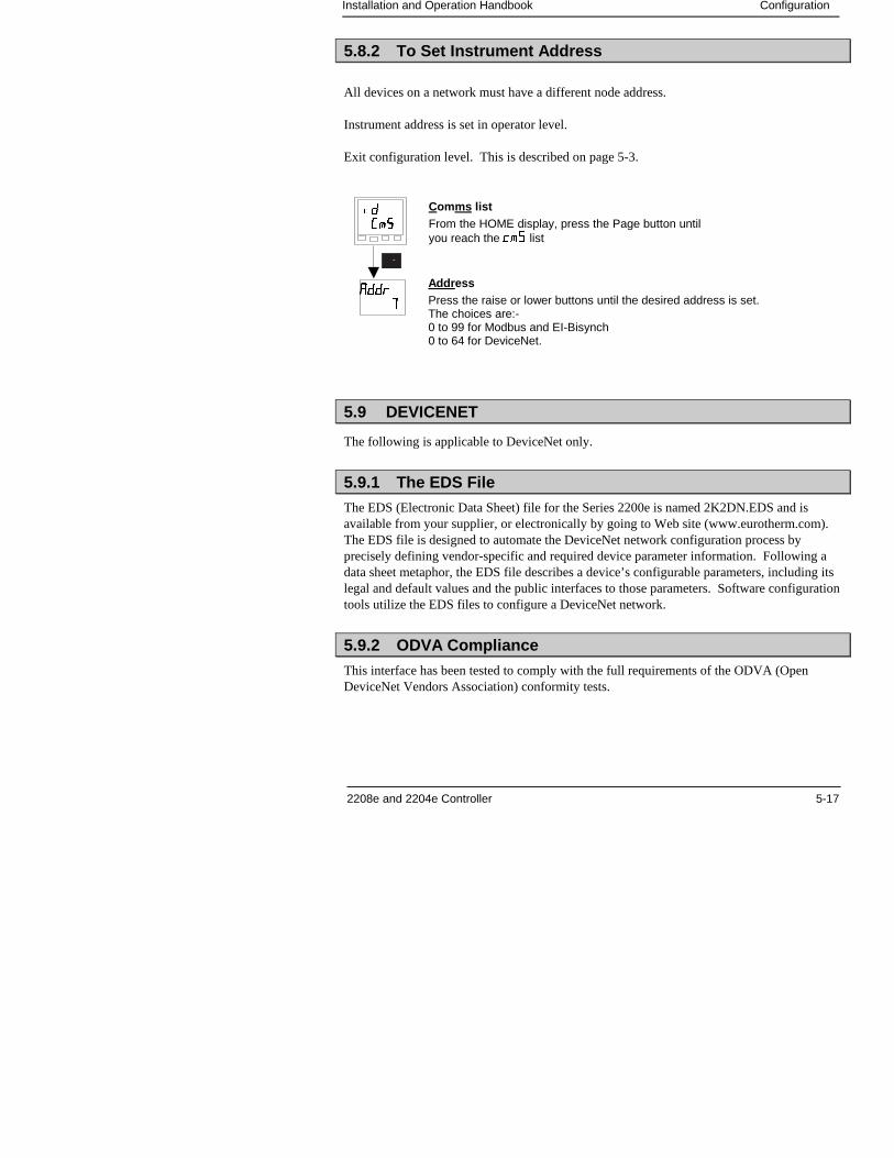
Installation and Operation Handbook Configuration
2208e and 2204e Controller 5-17
5.8.2 To Set Instrument Address
All devices on a network must have a different node address.
Instrument address is set in operator level.
Exit configuration level. This is described on page 5-3.
5.9 DEVICENET
The following is applicable to DeviceNet only.
5.9.1 The EDS File
The EDS (Electronic Data Sheet) file for the Series 2200e is named 2K2DN.EDS and isavailable from your supplier, or electronically by going to Web site (www.eurotherm.com).The EDS file is designed to automate the DeviceNet network configuration process byprecisely defining vendor-specific and required device parameter information. Following adata sheet metaphor, the EDS file describes a device’s configurable parameters, including itslegal and default values and the public interfaces to those parameters. Software configurationtools utilize the EDS files to configure a DeviceNet network.
5.9.2 ODVA Compliance
This interface has been tested to comply with the full requirements of the ODVA (OpenDeviceNet Vendors Association) conformity tests.
Comms listFrom the HOME display, press the Page button untilyou reach the �� list
AddressPress the raise or lower buttons until the desired address is set.The choices are:-0 to 99 for Modbus and EI-Bisynch0 to 64 for DeviceNet.
�
���
����
�
nstallation and O eration Handbook Configuration
5-18 2208e and 2204e Controller
Installation and Operation Handbook User Calibration
2208e and 2204e Controller 6-1
6 Chapter 6 USER CALIBRATION
6 Chapter 6 User calibration ................................................1
6.8 What is the Purpose of User Calibration?...................................... 2
6.9 User Calibration Enable ................................................................... 3
6.10 Single point calibration................................................................. 4
6.11 Two point calibration .................................................................... 5
6.12 Calibration points and Calibration offsets.................................. 6
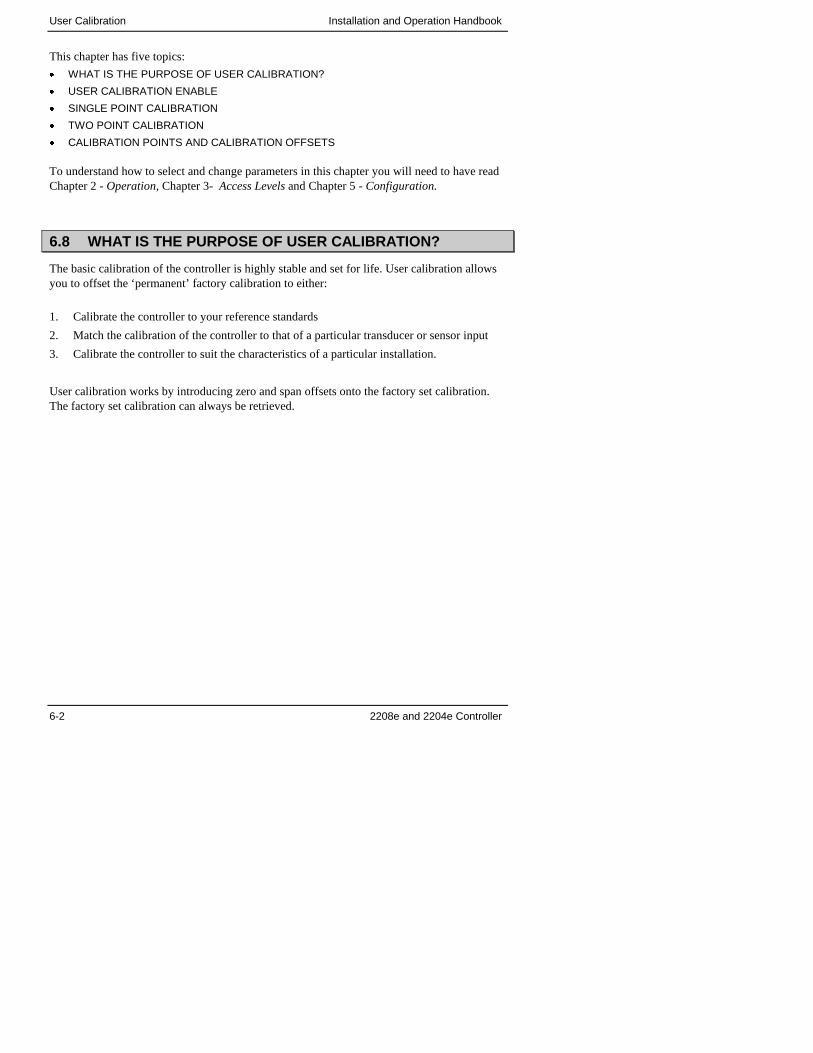
User Calibration Installation and Operation Handbook
6-2 2208e and 2204e Controller
This chapter has five topics:
� WHAT IS THE PURPOSE OF USER CALIBRATION?
� USER CALIBRATION ENABLE
� SINGLE POINT CALIBRATION
� TWO POINT CALIBRATION
� CALIBRATION POINTS AND CALIBRATION OFFSETS
To understand how to select and change parameters in this chapter you will need to have readChapter 2 - Operation, Chapter 3- Access Levels and Chapter 5 - Configuration.
6.8 WHAT IS THE PURPOSE OF USER CALIBRATION?
The basic calibration of the controller is highly stable and set for life. User calibration allowsyou to offset the ‘permanent’ factory calibration to either:
1. Calibrate the controller to your reference standards
2. Match the calibration of the controller to that of a particular transducer or sensor input
3. Calibrate the controller to suit the characteristics of a particular installation.
User calibration works by introducing zero and span offsets onto the factory set calibration.The factory set calibration can always be retrieved.
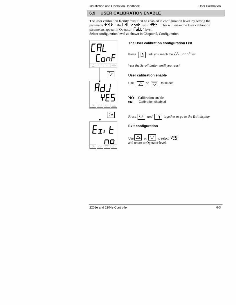
Installation and Operation Handbook User Calibration
2208e and 2204e Controller 6-3
6.9 USER CALIBRATION ENABLE
The User calibration facility must first be enabled in configuration level by setting theparameter ‘���' in the ��� �� list to '�� ' This will make the User calibrationparameters appear in Operator ‘����’ level.Select configuration level as shown in Chapter 5, Configuration
�������
����
� ���
The User calibration configuration List
Press until you reach the ‘��� ���� list
Press the Scroll button until you reach
User calibration enable
Use or to select:
�: Calibration enable��: Calibration disabled
Press and together to go to the Exit display
Exit configuration
Use or to select ‘�� ’and return to Operator level.
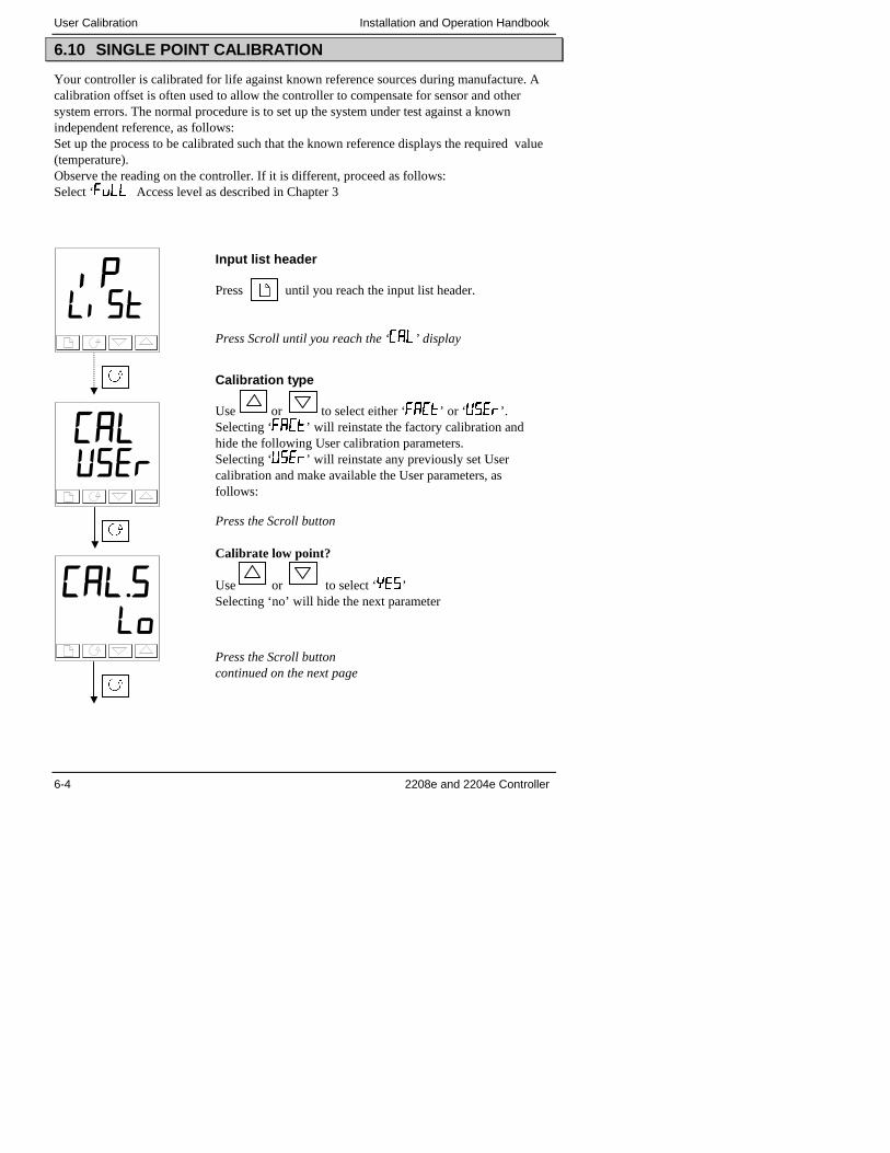
User Calibration Installation and Operation Handbook
6-4 2208e and 2204e Controller
6.10 SINGLE POINT CALIBRATION
Your controller is calibrated for life against known reference sources during manufacture. Acalibration offset is often used to allow the controller to compensate for sensor and othersystem errors. The normal procedure is to set up the system under test against a knownindependent reference, as follows:Set up the process to be calibrated such that the known reference displays the required value(temperature).Observe the reading on the controller. If it is different, proceed as follows:Select ‘���� Access level as described in Chapter 3
� �� ��
������
�������
Input list header
Press until you reach the input list header.
Press Scroll until you reach the ‘���’ display
Calibration type
Use or to select either ‘����’ or ‘� ��’.Selecting ‘����’ will reinstate the factory calibration andhide the following User calibration parameters.Selecting ‘� ��’ will reinstate any previously set Usercalibration and make available the User parameters, asfollows:
Press the Scroll button
Calibrate low point?
Use or to select ‘�� ’Selecting ‘no’ will hide the next parameter
Press the Scroll buttoncontinued on the next page
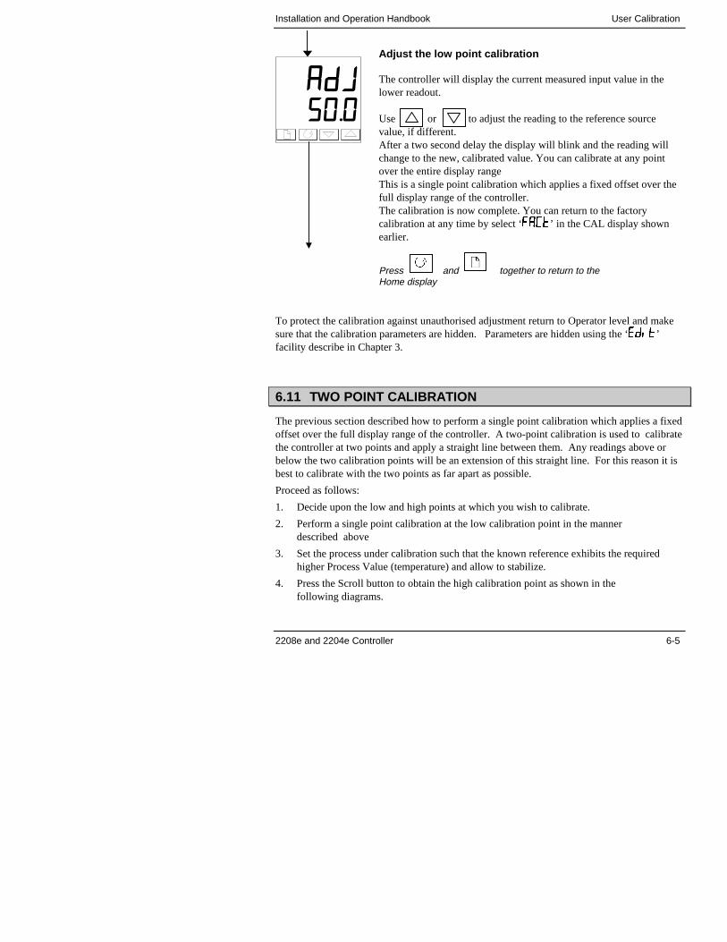
Installation and Operation Handbook User Calibration
2208e and 2204e Controller 6-5
To protect the calibration against unauthorised adjustment return to Operator level and makesure that the calibration parameters are hidden. Parameters are hidden using the ‘����’facility describe in Chapter 3.
6.11 TWO POINT CALIBRATION
The previous section described how to perform a single point calibration which applies a fixedoffset over the full display range of the controller. A two-point calibration is used to calibratethe controller at two points and apply a straight line between them. Any readings above orbelow the two calibration points will be an extension of this straight line. For this reason it isbest to calibrate with the two points as far apart as possible.
Proceed as follows:
1. Decide upon the low and high points at which you wish to calibrate.
2. Perform a single point calibration at the low calibration point in the mannerdescribed above
3. Set the process under calibration such that the known reference exhibits the requiredhigher Process Value (temperature) and allow to stabilize.
4. Press the Scroll button to obtain the high calibration point as shown in thefollowing diagrams.
�������
Adjust the low point calibration
The controller will display the current measured input value in thelower readout.
Use or to adjust the reading to the reference sourcevalue, if different.After a two second delay the display will blink and the reading willchange to the new, calibrated value. You can calibrate at any pointover the entire display rangeThis is a single point calibration which applies a fixed offset over thefull display range of the controller.The calibration is now complete. You can return to the factorycalibration at any time by select ‘����’ in the CAL display shownearlier.
Press and together to return to theHome display
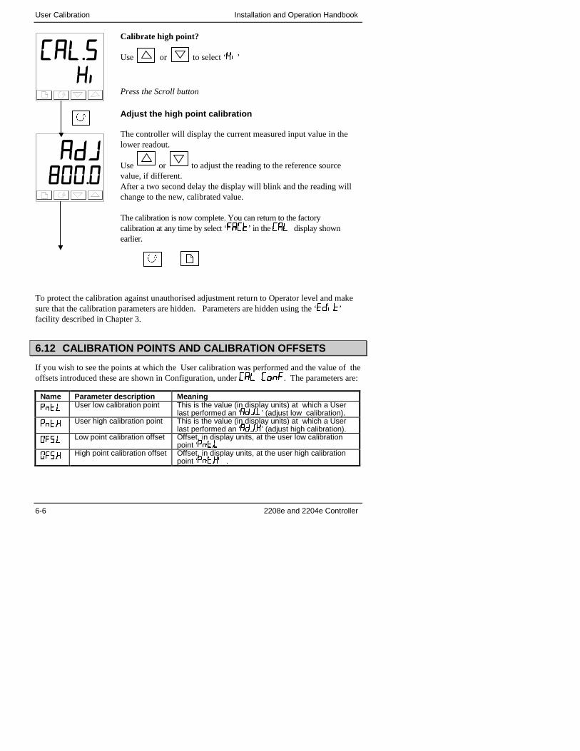
User Calibration Installation and Operation Handbook
6-6 2208e and 2204e Controller
To protect the calibration against unauthorised adjustment return to Operator level and makesure that the calibration parameters are hidden. Parameters are hidden using the ‘����’facility described in Chapter 3.
6.12 CALIBRATION POINTS AND CALIBRATION OFFSETS
If you wish to see the points at which the User calibration was performed and the value of theoffsets introduced these are shown in Configuration, under ��� ���. The parameters are:
Name Parameter description Meaning
�� �� User low calibration point This is the value (in display units) at which a Userlast performed an ‘�����’ (adjust low calibration).
�� �� User high calibration point This is the value (in display units) at which a Userlast performed an ‘�����’ (adjust high calibration).
����� Low point calibration offset Offset, in display units, at the user low calibrationpoint ‘�� ��
����� High point calibration offset Offset, in display units, at the user high calibrationpoint ‘�� ���.
������
��������
Calibrate high point?
Use or to select ‘��’
Press the Scroll button
Adjust the high point calibration
The controller will display the current measured input value in thelower readout.
Use or to adjust the reading to the reference sourcevalue, if different.After a two second delay the display will blink and the reading willchange to the new, calibrated value.
The calibration is now complete. You can return to the factorycalibration at any time by select ‘����’ in the ��� display shownearlier.

2208 and 2204 Controller 1-7
Installation and Operation Handbook Operation
Installation and Operation Handbook Alarm Operation
2208e and 2204e Controller 7-1
7 Chapter 7 ALARM CONFIGURATION
7 Chapter 7 ALARM CONFIGURATION................................1
7.1 DEFINITION OF ALARMS AND EVENTS......................................... 27.1.1 TYPES OF ALARMS...............................................................................2
7.2 DIGITAL OUTPUT FUNCTIONS ....................................................... 4
7.3 STEP1 - CONFIGURING THE FOUR ‘SOFT’ ALARMS ................... 5
7.4 STEP 2 - ATTACHING AN ALARM TO A PHYSICAL OUTPUT....... 6
7.5 STEP 3 - GROUPING ALARMS ON A SINGLE OUTPUT ................ 7
7.6 STEP 4 - REMOVING ALARMS FROM AN OUTPUT....................... 7
The 2200e series controllers are capable of very sophisticated alarm strategies and, althoughsetting up of alarms has already been covered in previous chapters, this section has beenincluded to enable operators and commissioning engineers to design their own strategies foroptimum plant operation.
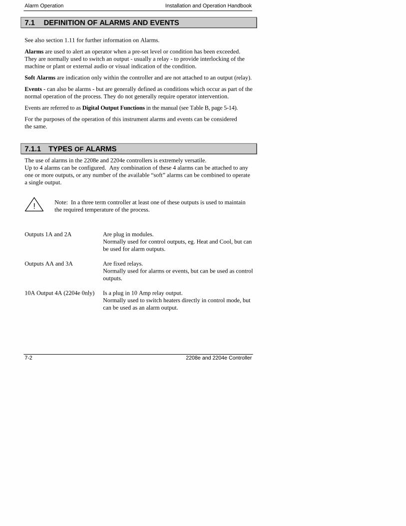
Alarm Operation Installation and Operation Handbook
7-2 2208e and 2204e Controller
7.1 DEFINITION OF ALARMS AND EVENTS
See also section 1.11 for further information on Alarms.
Alarms are used to alert an operator when a pre-set level or condition has been exceeded.They are normally used to switch an output - usually a relay - to provide interlocking of themachine or plant or external audio or visual indication of the condition.
Soft Alarms are indication only within the controller and are not attached to an output (relay).
Events - can also be alarms - but are generally defined as conditions which occur as part of thenormal operation of the process. They do not generally require operator intervention.
Events are referred to as Digital Output Functions in the manual (see Table B, page 5-14).
For the purposes of the operation of this instrument alarms and events can be consideredthe same.
7.1.1 TYPES OF ALARMS
The use of alarms in the 2208e and 2204e controllers is extremely versatile.Up to 4 alarms can be configured. Any combination of these 4 alarms can be attached to anyone or more outputs, or any number of the available “soft” alarms can be combined to operatea single output.
Note: In a three term controller at least one of these outputs is used to maintainthe required temperature of the process.
Outputs 1A and 2A Are plug in modules.Normally used for control outputs, eg. Heat and Cool, but canbe used for alarm outputs.
Outputs AA and 3A Are fixed relays.Normally used for alarms or events, but can be used as controloutputs.
10A Output 4A (2204e 0nly) Is a plug in 10 Amp relay output.Normally used to switch heaters directly in control mode, butcan be used as an alarm output.
!
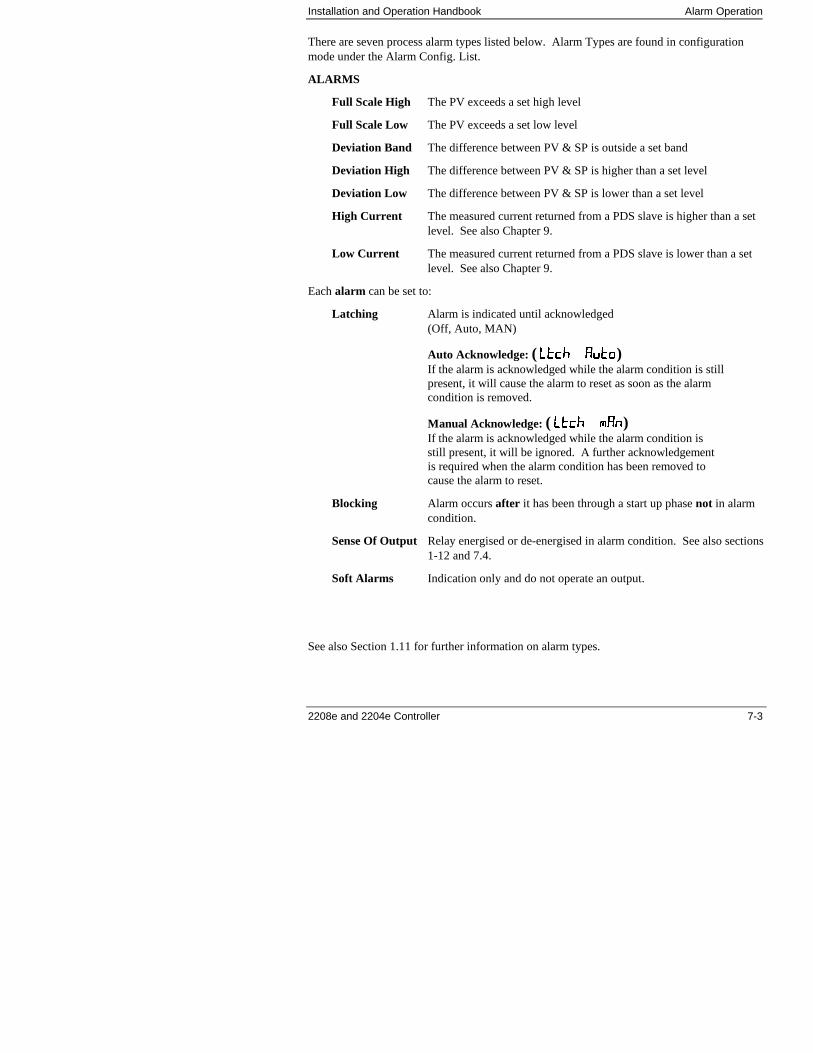
Installation and Operation Handbook Alarm Operation
2208e and 2204e Controller 7-3
There are seven process alarm types listed below. Alarm Types are found in configurationmode under the Alarm Config. List.
ALARMS
Full Scale High The PV exceeds a set high level
Full Scale Low The PV exceeds a set low level
Deviation Band The difference between PV & SP is outside a set band
Deviation High The difference between PV & SP is higher than a set level
Deviation Low The difference between PV & SP is lower than a set level
High Current The measured current returned from a PDS slave is higher than a setlevel. See also Chapter 9.
Low Current The measured current returned from a PDS slave is lower than a setlevel. See also Chapter 9.
Each alarm can be set to:
Latching Alarm is indicated until acknowledged(Off, Auto, MAN)
Auto Acknowledge: ( �������� ��������)If the alarm is acknowledged while the alarm condition is stillpresent, it will cause the alarm to reset as soon as the alarmcondition is removed.
Manual Acknowledge: ( �������� ��)If the alarm is acknowledged while the alarm condition isstill present, it will be ignored. A further acknowledgementis required when the alarm condition has been removed tocause the alarm to reset.
Blocking Alarm occurs after it has been through a start up phase not in alarmcondition.
Sense Of Output Relay energised or de-energised in alarm condition. See also sections1-12 and 7.4.
Soft Alarms Indication only and do not operate an output.
See also Section 1.11 for further information on alarm types.
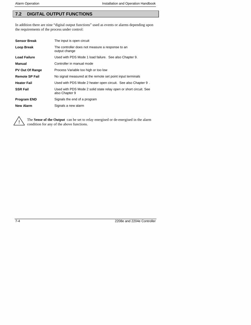
Alarm Operation Installation and Operation Handbook
7-4 2208e and 2204e Controller
7.2 DIGITAL OUTPUT FUNCTIONS
In addition there are nine “digital output functions” used as events or alarms depending uponthe requirements of the process under control:
Sensor Break The input is open circuit
Loop Break The controller does not measure a response to anoutput change
Load Failure Used with PDS Mode 1 load failure. See also Chapter 9.
Manual Controller in manual mode
PV Out Of Range Process Variable too high or too low
Remote SP Fail No signal measured at the remote set point input terminals
Heater Fail Used with PDS Mode 2 heater open circuit. See also Chapter 9 .
SSR Fail Used with PDS Mode 2 solid state relay open or short circuit. Seealso Chapter 9
Program END Signals the end of a program
New Alarm Signals a new alarm
The Sense of the Output can be set to relay energised or de-energised in the alarmcondition for any of the above functions.!
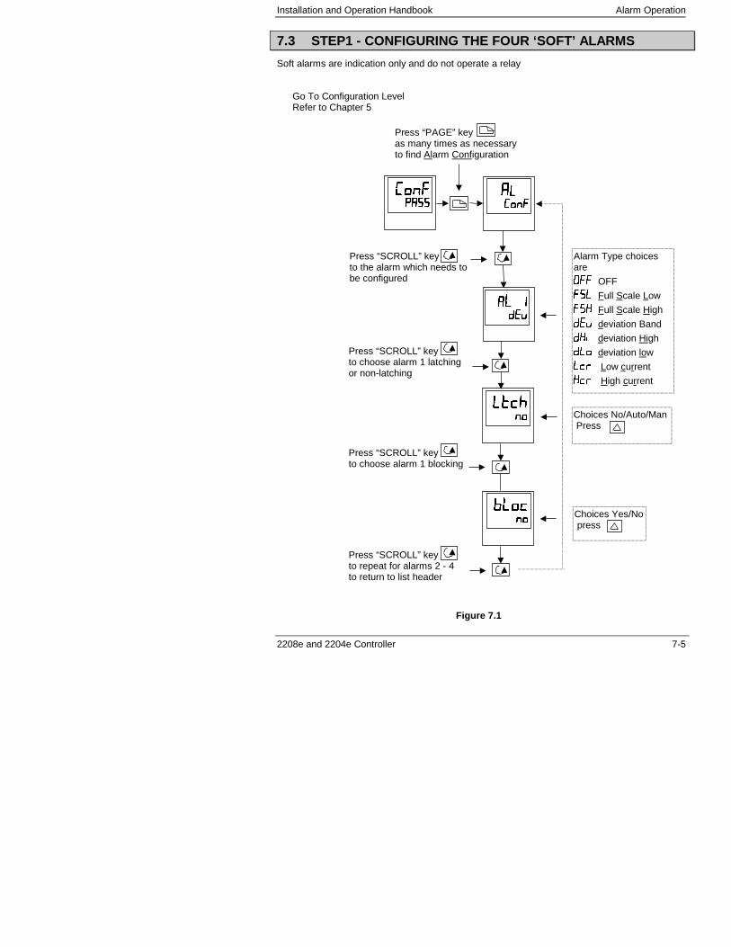
Installation and Operation Handbook Alarm Operation
2208e and 2204e Controller 7-5
7.3 STEP1 - CONFIGURING THE FOUR ‘SOFT’ ALARMS
Soft alarms are indication only and do not operate a relay
Go To Configuration LevelRefer to Chapter 5
����������������
������������
���� ����
����������
Press “PAGE” keyas many times as necessaryto find Alarm Configuration
Press “SCROLL” keyto the alarm which needs tobe configured
Alarm Type choicesare
��� OFF
�� Full Scale Low
��� Full Scale High
�� deviation Band
��� deviation High
� � deviation low
�� Low current
��� High current
Press “SCROLL” keyto choose alarm 1 latchingor non-latching
Choices No/Auto/Man Press
����������
Press “SCROLL” keyto choose alarm 1 blocking
Choices Yes/No press
Press “SCROLL” keyto repeat for alarms 2 - 4to return to list header
Figure 7.1
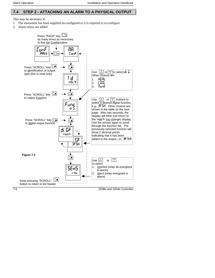
Alarm Operation Installation and Operation Handbook
7-6 2208e and 2204e Controller
7.4 STEP 2 - ATTACHING AN ALARM TO A PHYSICAL OUTPUT
This may be necessary if:1. The instrument has been supplied un-configured or it is required to re-configure2. Alarm relays are added
������������
� ��� ��� �
��������������
Press “PAGE” keyas many times as necessaryto find AA Configuration
Press “SCROLL” keyto identification of outputtype (this is read only)
Press “SCROLL” keyto output Function
����������������
������������
Use or to select ���Other choices are:
1. ���
2. ���
3. ���
Use or buttons toselect a desired digital function,e.g., ����. Other choices areshown in the table on the nextpage. After two seconds, thedisplay will blink and return tothe ‘����’ (no change) display.Use the arrows again to scrollthrough the function list. Thepreviously selected function willshow 2 decimal pointsindicating that it has beenadded to the output, i.e., ������.
Use orto select:1. inverted (relay de-energised
in alarm)2. direct (relay energised in
alarm)
Press “SCROLL” keyto digital output function
Keep pressing “SCROLL”button to return to list header
������������
����������������
Figure 7.2
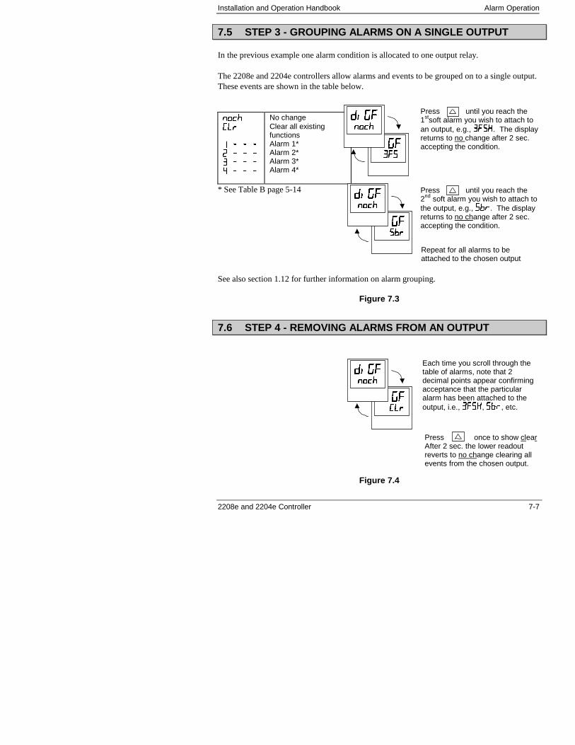
Installation and Operation Handbook Alarm Operation
2208e and 2204e Controller 7-7
7.5 STEP 3 - GROUPING ALARMS ON A SINGLE OUTPUT
In the previous example one alarm condition is allocated to one output relay.
The 2208e and 2204e controllers allow alarms and events to be grouped on to a single output.These events are shown in the table below.
���� No change� �
� � � �� � � �� � � � � � �
Clear all existingfunctionsAlarm 1*Alarm 2*Alarm 3*Alarm 4*
* See Table B page 5-14
See also section 1.12 for further information on alarm grouping.
Figure 7.3
7.6 STEP 4 - REMOVING ALARMS FROM AN OUTPUT
Figure 7.4
�����!��!�
����������
����������������
����������������
Press until you reach the1stsoft alarm you wish to attach toan output, e.g., ����. The displayreturns to no change after 2 sec.accepting the condition.
Press until you reach the2nd soft alarm you wish to attach tothe output, e.g., �!�. The displayreturns to no change after 2 sec.accepting the condition.
Repeat for all alarms to beattached to the chosen output
Press once to show clearAfter 2 sec. the lower readoutreverts to no change clearing allevents from the chosen output.
Each time you scroll through thetable of alarms, note that 2decimal points appear confirmingacceptance that the particularalarm has been attached to theoutput, i.e., ����, �!�, etc.
����� �� �
����������������

Alarm Operation Installation and Operation Handbook
7-8 2208e and 2204e Controller
Installation and Operation Handbook Valve Position
2208e and 2204e Controller 8-1
8. Chapter 8 MOTORISED VALVE CONTROL
8. Chapter 8 MOTORISED VALVE CONTROL ....................1
8.1. Parameters For Motorised Valve Control ....................................... 2
8.2. Commissioning the Motorised Valve Controller ........................... 28.2.1. Adjusting the minimum on-time ‘������ ...............................................2
8.3. MOTORISED VALVE APPLICATIONS ............................................. 38.3.1. Auto Tuning.............................................................................................38.3.2. 2200e Valve Positioner Set-up Table .....................................................3
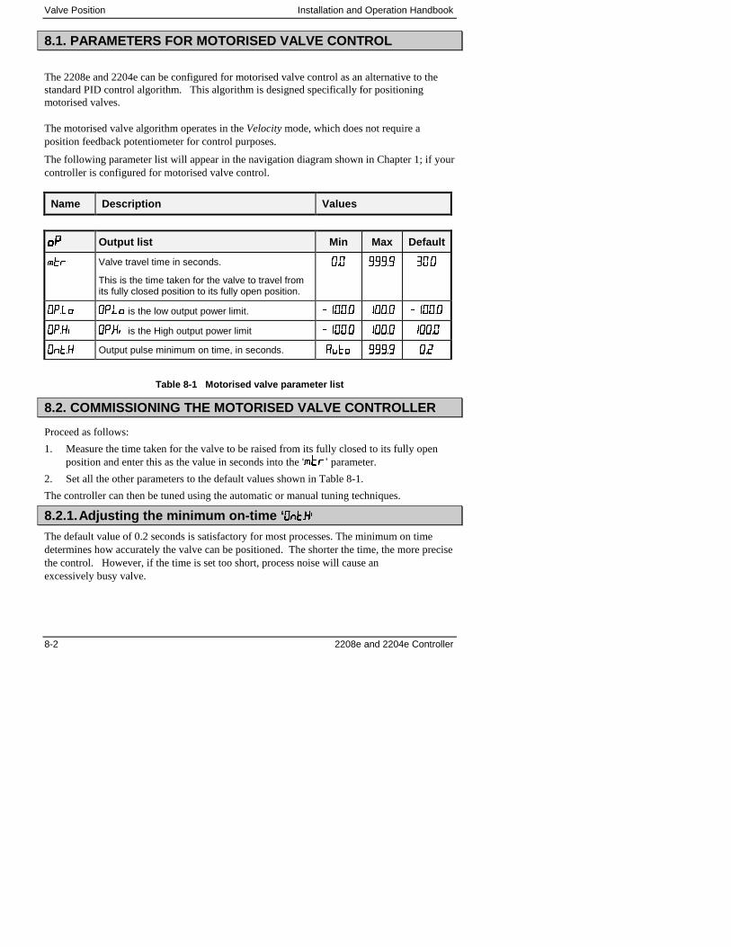
Valve Position Installation and Operation Handbook
8-2 2208e and 2204e Controller
8.1. PARAMETERS FOR MOTORISED VALVE CONTROL
The 2208e and 2204e can be configured for motorised valve control as an alternative to thestandard PID control algorithm. This algorithm is designed specifically for positioningmotorised valves.
The motorised valve algorithm operates in the Velocity mode, which does not require aposition feedback potentiometer for control purposes.
The following parameter list will appear in the navigation diagram shown in Chapter 1; if yourcontroller is configured for motorised valve control.
Name Description Values
���� Output list Min Max Default
��� Valve travel time in seconds.
This is the time taken for the valve to travel fromits fully closed position to its fully open position.
��� ����� ����
��� ��� is the low output power limit. � ���� ���� � ����
���� ���� is the High output power limit � ���� ���� ����
����� Output pulse minimum on time, in seconds. ���� ����� ���
Table 8-1 Motorised valve parameter list
8.2. COMMISSIONING THE MOTORISED VALVE CONTROLLER
Proceed as follows:
1. Measure the time taken for the valve to be raised from its fully closed to its fully openposition and enter this as the value in seconds into the ‘�’ parameter.
2. Set all the other parameters to the default values shown in Table 8-1.
The controller can then be tuned using the automatic or manual tuning techniques.
8.2.1. Adjusting the minimum on-time ‘ ������������
The default value of 0.2 seconds is satisfactory for most processes. The minimum on timedetermines how accurately the valve can be positioned. The shorter the time, the more precisethe control. However, if the time is set too short, process noise will cause anexcessively busy valve.
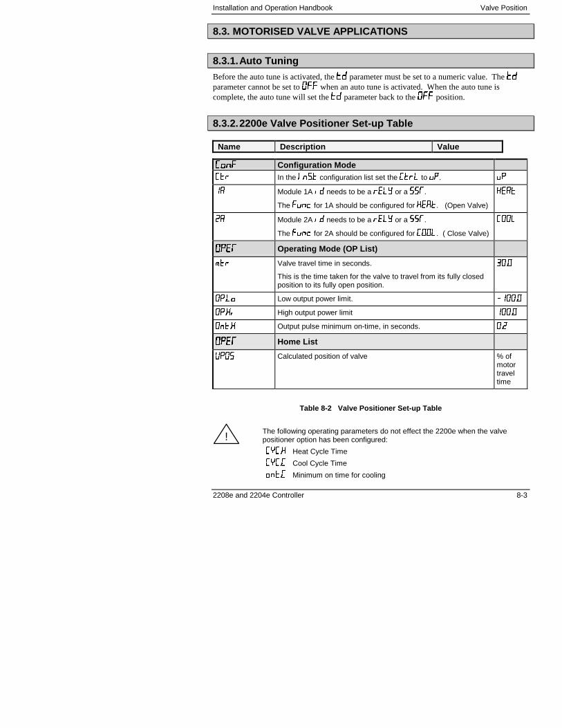
Installation and Operation Handbook Valve Position
2208e and 2204e Controller 8-3
8.3. MOTORISED VALVE APPLICATIONS
8.3.1. Auto Tuning
Before the auto tune is activated, the �� parameter must be set to a numeric value. The ��parameter cannot be set to � when an auto tune is activated. When the auto tune iscomplete, the auto tune will set the �� parameter back to the � position.
8.3.2. 2200e Valve Positioner Set-up Table
Name Description Value
��� ��� Configuration Mode��� In the ���� configuration list set the ��� to �. �
� Module 1A �� needs to be a ��� or a ���.
The ���� for 1A should be configured for � !�. (Open Valve)
����
�� Module 2A �� needs to be a ��� or a ���.
The ���� for 2A should be configured for ���. ( Close Valve)
���
�������� Operating Mode (OP List)
��� Valve travel time in seconds.
This is the time taken for the valve to travel from its fully closedposition to its fully open position.
����
��� Low output power limit. � ����
���� High output power limit ����
����� Output pulse minimum on-time, in seconds. ���
�������� Home List
"�� Calculated position of valve % ofmotortraveltime
Table 8-2 Valve Positioner Set-up Table
The following operating parameters do not effect the 2200e when the valvepositioner option has been configured:
�#��� Heat Cycle Time
�#��� Cool Cycle Time
����� Minimum on time for cooling
!

Valve Position Installation and Operation Handbook
8-4 2208e and 2204e Controller
Installation and Operation Handbook Load Current Monitoring and Diagnostics
2208e and 2204e Controller 9-1
9 Chapter 9 LOAD CURRENT MONITORING ANDDIAGNOSTICS
9 Chapter 9 LOAD CURRENT MONITORING ANDDIAGNOSTICS..........................................................................1
9.1 LOAD CURRENT MONITORING AND DIAGNOSTICS.................... 2
9.2 EXAMPLE WIRING DIAGRAM (FOR MODE 1 & 2 OPERATION)... 3
EXAMPLE WIRING DIAGRAM (FOR MODE 5 OPERATION) ................. 4
9.4 OPERATION ...................................................................................... 5To Read Load Current (modes 2 and 5 only).....................................................59.4.2 To Display Load Current Continuously in the Lower Readout (modes 2and 5 only) .........................................................................................................59.4.3 Display Modes.......................................................................................59.4.4 How Heater Alarms Are Displayed........................................................6
9.5 TO SET THE ALARM TRIP LEVELS ................................................ 7
9.6 RELAY OUTPUTS ............................................................................. 7
9.7 TO CONFIGURE PDS LOAD CURRENT DIAGNOSTICS................ 89.7.1 To configure the Logic Module for PDS modes 1 or 2 ..........................89.7.2 To configure logic input a for pds (Mode 5 only) ...................................9
TO CONFIGURE LOW AND HIGH CURRENT TRIP ALARMS.............. 10
9.9 TO ATTACH SOFT ALARMS TO A RELAY OUTPUT ................... 11
9.10 THE SCALING FACTOR ............................................................. 129.10.1 To adjust the scaling factor.............................................................12
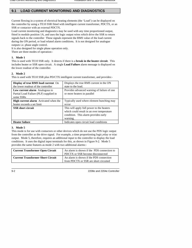
Load Current Monitoring and Diagnostics Installation and O eration Handbook
9-2 2208e and 2204e Controller
9.1 LOAD CURRENT MONITORING AND DIAGNOSTICS
Current flowing in a system of electrical heating elements (the ‘Load’) can be displayed onthe controller by using a TE10 SSR fitted with intelligent current transformer, PDCTX, or anSSR or contactor with an external PDCTX.Load current monitoring and diagnostics may be used with any time proportioned output,fitted in module position 1A, and uses the logic output wires which drive the SSR to returnsignals back to the controller These signals represent the RMS value of the load currentduring the ON period, or load related alarm conditions. It is not designed for analogueoutputs i.e. phase angle control.It is also designed for single phase operation only.There are three modes of operation:-
1. Mode 1This is used with TE10 SSR only. It detects if there is a break in the heater circuit. Thisincludes heater or SSR open circuit. A single Load Failure alarm message is displayed onthe lower readout of the controller.
2. Mode 2This is used with TE10 SSR plus PD/CTX intelligent current transformer, and provides:-
Display of true RMS load current Onthe lower readout of the controller
Displays the true RMS current in the ONstate to the load.
Low current alarm Analogous toPartial Load Failure (PLF) supplied insome SSRs
Provides advanced warning of failure of oneor more heaters in parallel
High current alarm Activated when theheater exceeds a set limit
Typically used where element bunching mayoccur
SSR short circuit This will apply full power to the heaterswhich could result in an over temperaturecondition. This alarm provides earlywarning.
Heater failure Indicates open circuit load conditions
3. Mode 5This mode is for use with contactors or other devices which do not use the PDS logic outputfrom the controller as the drive signal. For example, a time proportioning logic,relay or triacoutput. Mode 5, therefore, requires an additional input to the controller to display the loadconditions. It uses the digital input terminals for this, as shown in Figure 9-2. Mode 5provides the same features as mode 2 with two additional alarms:-
Current Transformer Open Circuit An alarm is shown if the PDS connection toPDCTX or SSR become disconnected
Current Transformer Short Circuit An alarm is shown if the PDS connectionfrom PDCTX or SSR are short circuited
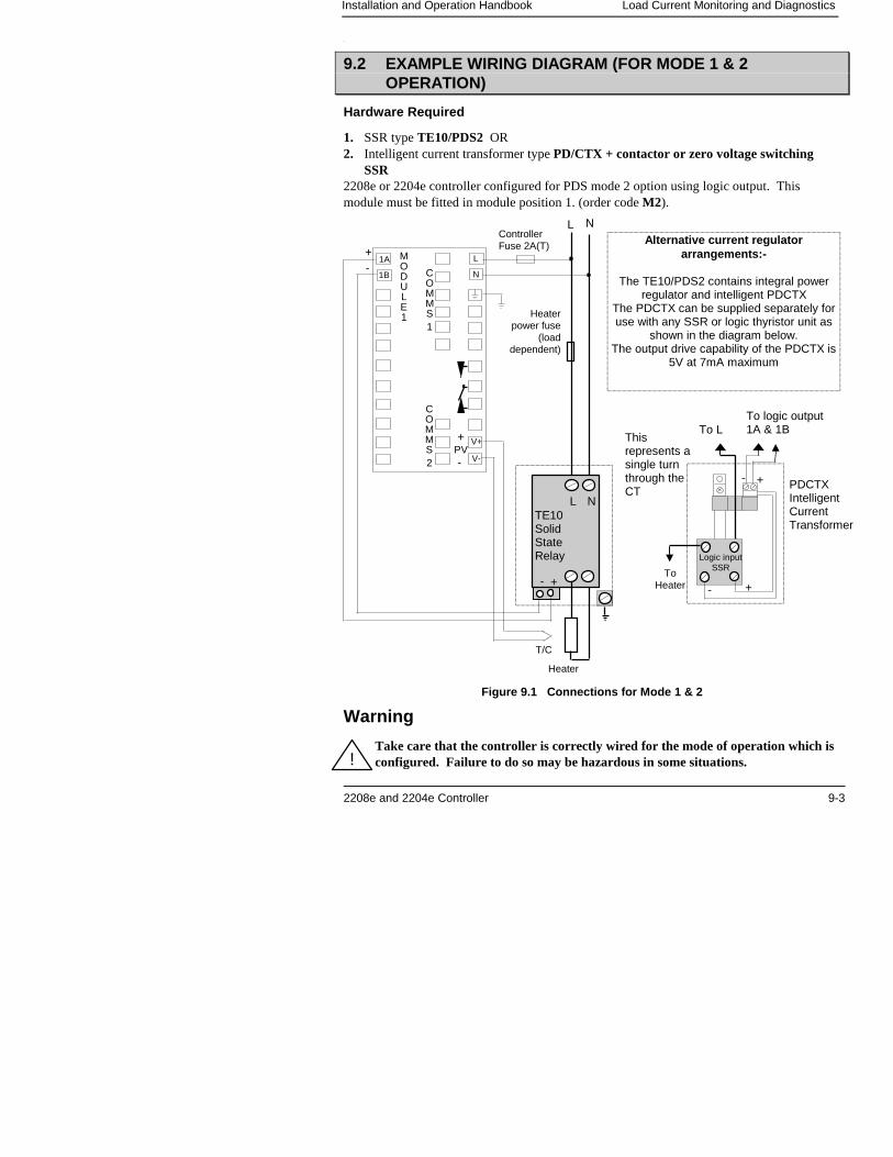
Installation and Operation Handbook Load Current Monitoring and Diagnostics
2208e and 2204e Controller 9-3
1.
9.2 EXAMPLE WIRING DIAGRAM (FOR MODE 1 & 2OPERATION)
Hardware Required
1. SSR type TE10/PDS2 OR2. Intelligent current transformer type PD/CTX + contactor or zero voltage switching
SSR2208e or 2204e controller configured for PDS mode 2 option using logic output. Thismodule must be fitted in module position 1. (order code M2).
Figure 9.1 Connections for Mode 1 & 2
Warning
Take care that the controller is correctly wired for the mode of operation which isconfigured. Failure to do so may be hazardous in some situations.
Heater
Heaterpower fuse
(loaddependent)
L NControllerFuse 2A(T)
N
L
V+
V-
1B
1A MODULE1
COMMS1
+-
+PV -
COMMS2
Alternative current regulatorarrangements:-
The TE10/PDS2 contains integral powerregulator and intelligent PDCTX
The PDCTX can be supplied separately foruse with any SSR or logic thyristor unit as
shown in the diagram below.The output drive capability of the PDCTX is
5V at 7mA maximum
PDCTXIntelligentCurrentTransformer
Logic inputSSR
+
+-
-
ToHeater
To LTo logic output1A & 1B
TE10SolidStateRelay
T/C
+-
L N
Thisrepresents asingle turnthrough theCT
!
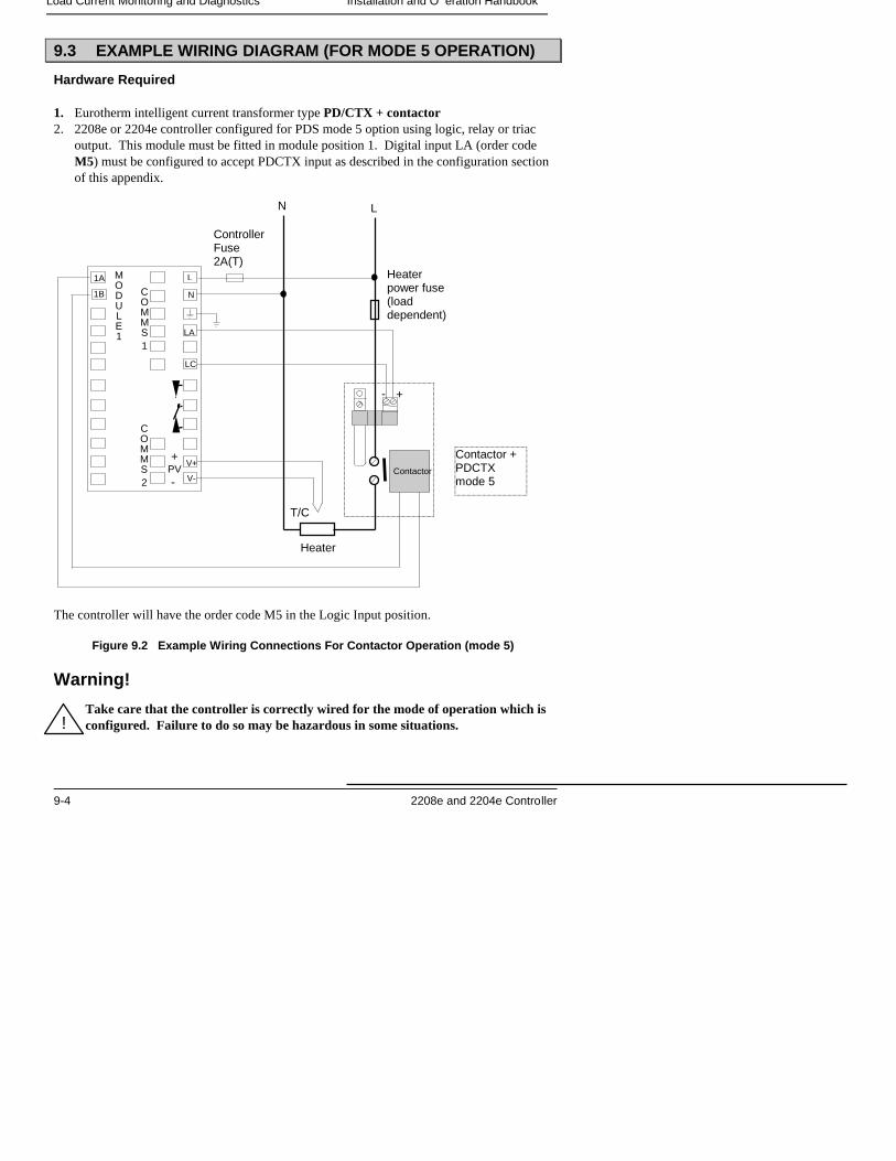
Load Current Monitoring and Diagnostics Installation and O eration Handbook
9-4 2208e and 2204e Controller
9.3 EXAMPLE WIRING DIAGRAM (FOR MODE 5 OPERATION)
Hardware Required
1. Eurotherm intelligent current transformer type PD/CTX + contactor2. 2208e or 2204e controller configured for PDS mode 5 option using logic, relay or triac
output. This module must be fitted in module position 1. Digital input LA (order codeM5) must be configured to accept PDCTX input as described in the configuration sectionof this appendix.
The controller will have the order code M5 in the Logic Input position.
Figure 9.2 Example Wiring Connections For Contactor Operation (mode 5)
Warning!
Take care that the controller is correctly wired for the mode of operation which isconfigured. Failure to do so may be hazardous in some situations.
Contactor +PDCTXmode 5
+-
Contactor
Heaterpower fuse(loaddependent)
LN
ControllerFuse2A(T)
N
L
V+
V-
1B
1A MODULE1
COMMS1
+PV -
COMMS2
Heater
T/C
LA
LC
!
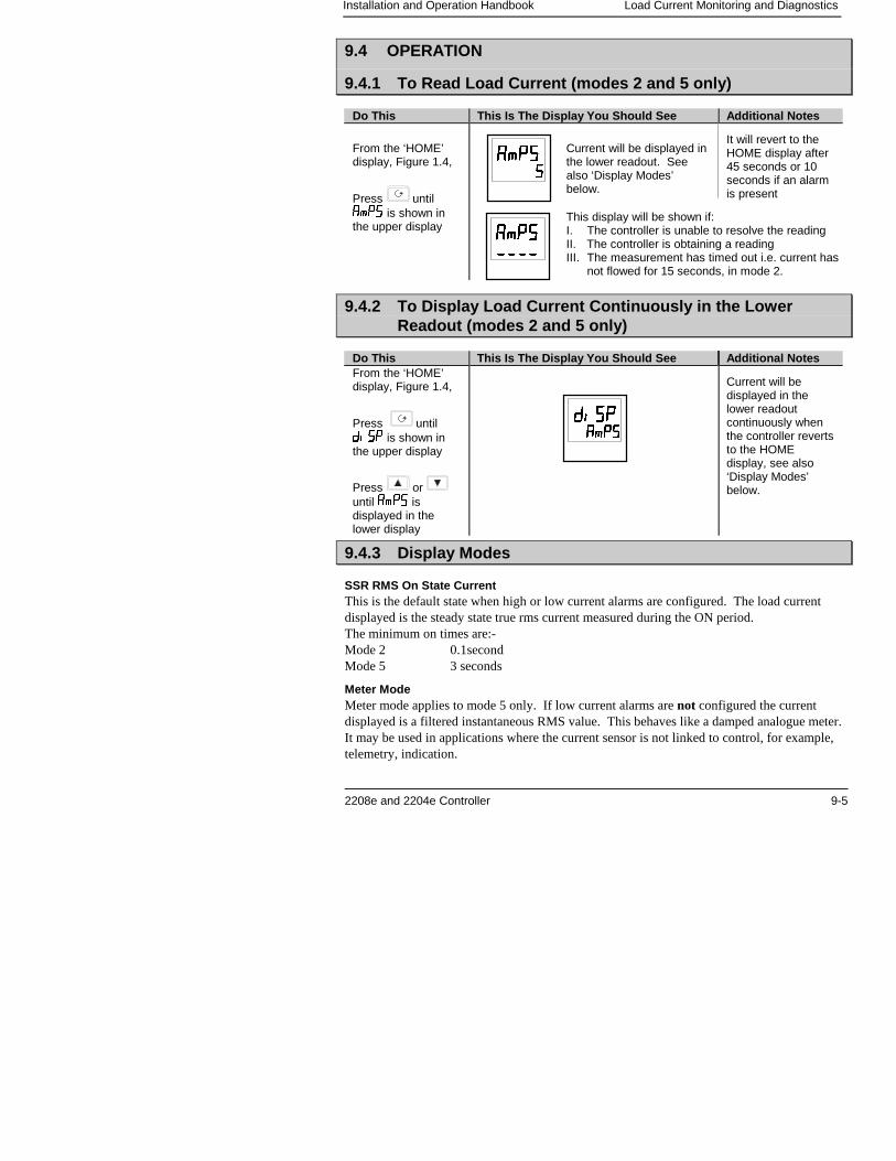
Installation and Operation Handbook Load Current Monitoring and Diagnostics
2208e and 2204e Controller 9-5
9.4 OPERATION
9.4.1 To Read Load Current (modes 2 and 5 only)
Do This This Is The Display You Should See Additional Notes
From the ‘HOME’display, Figure 1.4,
Press until���� is shown inthe upper display
It will revert to theHOME display after45 seconds or 10seconds if an alarmis present
9.4.2 To Display Load Current Continuously in the LowerReadout (modes 2 and 5 only)
Do This This Is The Display You Should See Additional NotesFrom the ‘HOME’display, Figure 1.4,
Press until���� is shown inthe upper display
Press or until ���� isdisplayed in thelower display
Current will bedisplayed in thelower readoutcontinuously whenthe controller revertsto the HOMEdisplay, see also‘Display Modes’below.
9.4.3 Display Modes
SSR RMS On State CurrentThis is the default state when high or low current alarms are configured. The load currentdisplayed is the steady state true rms current measured during the ON period.The minimum on times are:-Mode 2 0.1secondMode 5 3 seconds
Meter ModeMeter mode applies to mode 5 only. If low current alarms are not configured the currentdisplayed is a filtered instantaneous RMS value. This behaves like a damped analogue meter.It may be used in applications where the current sensor is not linked to control, for example,telemetry, indication.
����������
��������
��������
����������������
This display will be shown if:I. The controller is unable to resolve the readingII. The controller is obtaining a readingIII. The measurement has timed out i.e. current has
not flowed for 15 seconds, in mode 2.
Current will be displayed inthe lower readout. Seealso ‘Display Modes’below.
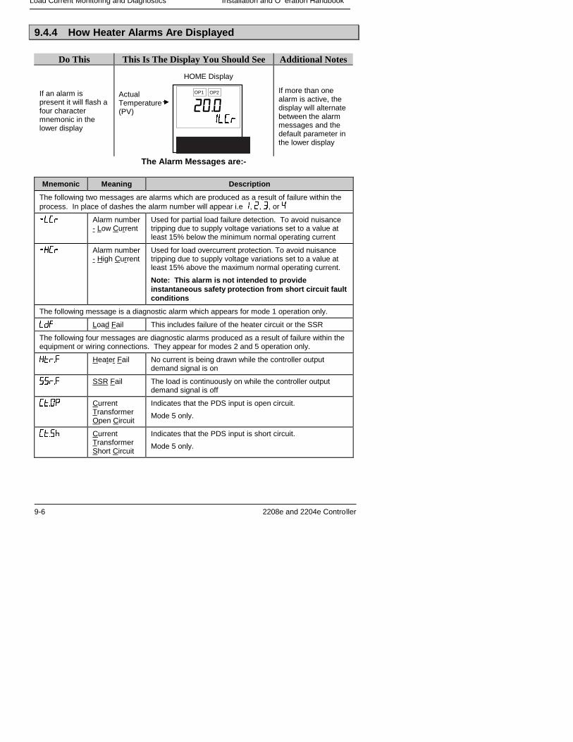
Load Current Monitoring and Diagnostics Installation and O eration Handbook
9-6 2208e and 2204e Controller
9.4.4 How Heater Alarms Are Displayed
Do This This Is The Display You Should See Additional Notes
If an alarm ispresent it will flash afour charactermnemonic in thelower display
If more than onealarm is active, thedisplay will alternatebetween the alarmmessages and thedefault parameter inthe lower display
The Alarm Messages are:-
Mnemonic Meaning Description
The following two messages are alarms which are produced as a result of failure within theprocess. In place of dashes the alarm number will appear i.e �, �, , or
�� � Alarm number- Low Current
Used for partial load failure detection. To avoid nuisancetripping due to supply voltage variations set to a value atleast 15% below the minimum normal operating current
�� � Alarm number- High Current
Used for load overcurrent protection. To avoid nuisancetripping due to supply voltage variations set to a value atleast 15% above the maximum normal operating current.
Note: This alarm is not intended to provideinstantaneous safety protection from short circuit faultconditions
The following message is a diagnostic alarm which appears for mode 1 operation only.
��� Load Fail This includes failure of the heater circuit or the SSR
The following four messages are diagnostic alarms produced as a result of failure within theequipment or wiring connections. They appear for modes 2 and 5 operation only.
����� Heater Fail No current is being drawn while the controller outputdemand signal is on
����� SSR Fail The load is continuously on while the controller outputdemand signal is off
���� CurrentTransformerOpen Circuit
Indicates that the PDS input is open circuit.
Mode 5 only.
���� CurrentTransformerShort Circuit
Indicates that the PDS input is short circuit.
Mode 5 only.
ActualTemperature(PV)
HOME Display
��������
OP1 OP2
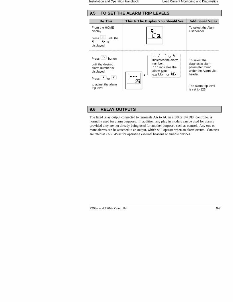
Installation and Operation Handbook Load Current Monitoring and Diagnostics
2208e and 2204e Controller 9-7
9.5 TO SET THE ALARM TRIP LEVELS
Do This This Is The Display You Should See Additional Notes
From the HOMEdisplay
press until the�� ������ ���� isdisplayed
Press button
until the desiredalarm number isdisplayed
Press or
to adjust the alarmtrip level
To select the AlarmList header
To select thediagnostic alarmparameter foundunder the Alarm Listheader
The alarm trip levelis set to 123
9.6 RELAY OUTPUTS
The fixed relay output connected to terminals AA to AC in a 1/8 or 1/4 DIN controller isnormally used for alarm purposes. In addition, any plug in module can be used for alarmsprovided they are not already being used for another purpose , such as control. Any one ormore alarms can be attached to an output, which will operate when an alarm occurs. Contactsare rated at 2A 264Vac for operating external beacons or audible devices.
��������
����������
� � or indicates the alarmnumber;��� indicates thealarm type:-e.g. � � or � �
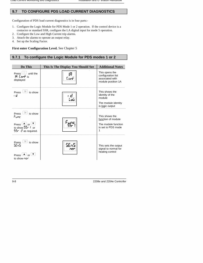
Load Current Monitoring and Diagnostics Installation and O eration Handbook
9-8 2208e and 2204e Controller
9.7 TO CONFIGURE PDS LOAD CURRENT DIAGNOSTICS
Configuration of PDS load current diagnostics is in four parts:-
1. Configure the Logic Module for PDS Mode 1 or 2 operation. If the control device is acontactor or standard SSR, configure the LA digital input for mode 5 operation.
2. Configure the Low and High Current trip alarms.3. Attach the alarms to operate an output relay.4. Set up the Scaling Factor.
First enter Configuration Level. See Chapter 5
9.7.1 To configure the Logic Module for PDS modes 1 or 2
Do This This Is The Display You Should See Additional Notes
Press until the�� ��� isdisplayed
Press to show��
Press to show����
Press or to show ���� or��� � as required.
Press to show����
Press or to show ���
This opens theconfiguration listassociated withmodule position 1A
This shows theidentity of themodule
The module identityis logic output
This shows thefunction of module
The module functionis set to PDS mode1
This sets the outputsignal to normal forheating control
�� ��� ���
����������
�� ��� �������
�� ��� �������
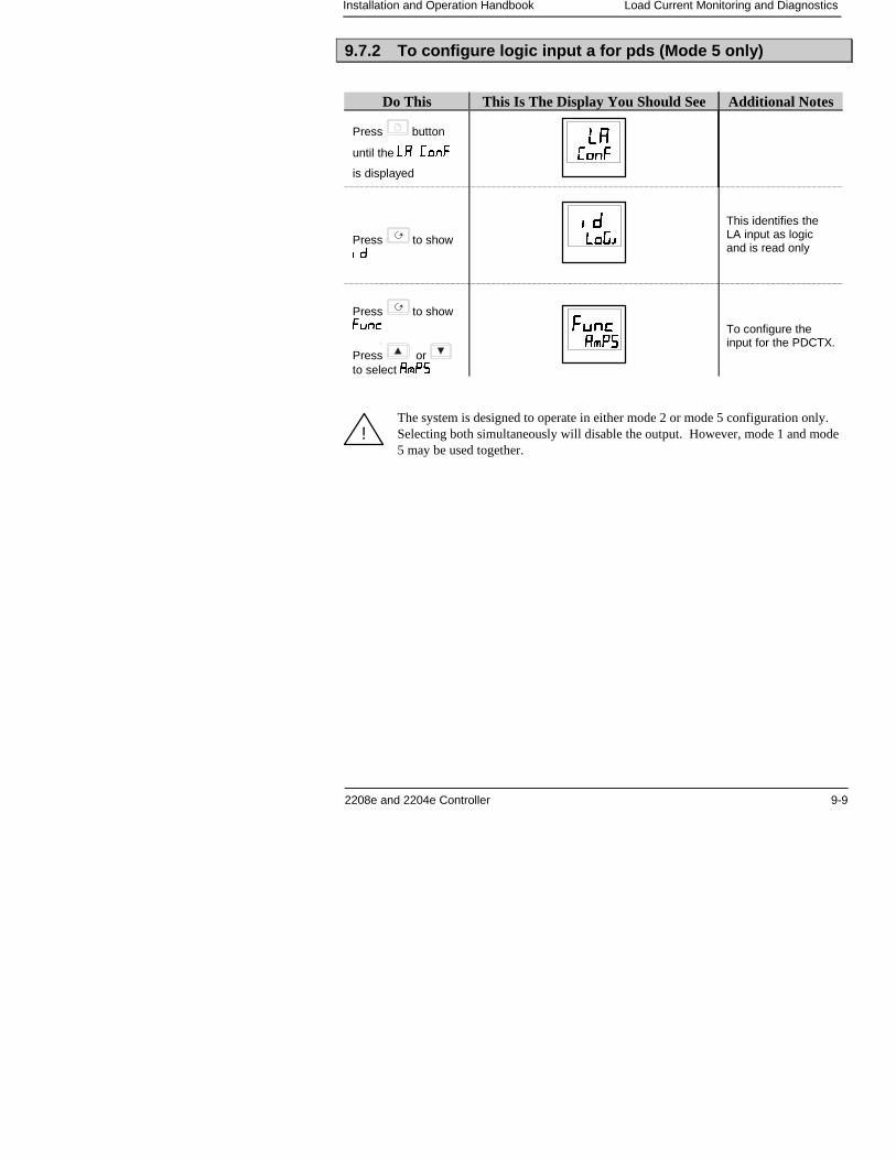
Installation and Operation Handbook Load Current Monitoring and Diagnostics
2208e and 2204e Controller 9-9
9.7.2 To configure logic input a for pds (Mode 5 only)
Do This This Is The Display You Should See Additional Notes
Press button
until the �� ���
is displayed
Press to show��
Press to show����
Press or to select ����
This identifies theLA input as logicand is read only
To configure theinput for the PDCTX.
The system is designed to operate in either mode 2 or mode 5 configuration only.Selecting both simultaneously will disable the output. However, mode 1 and mode5 may be used together.
�� ��� ���
��������������
�� ��� ���������
!
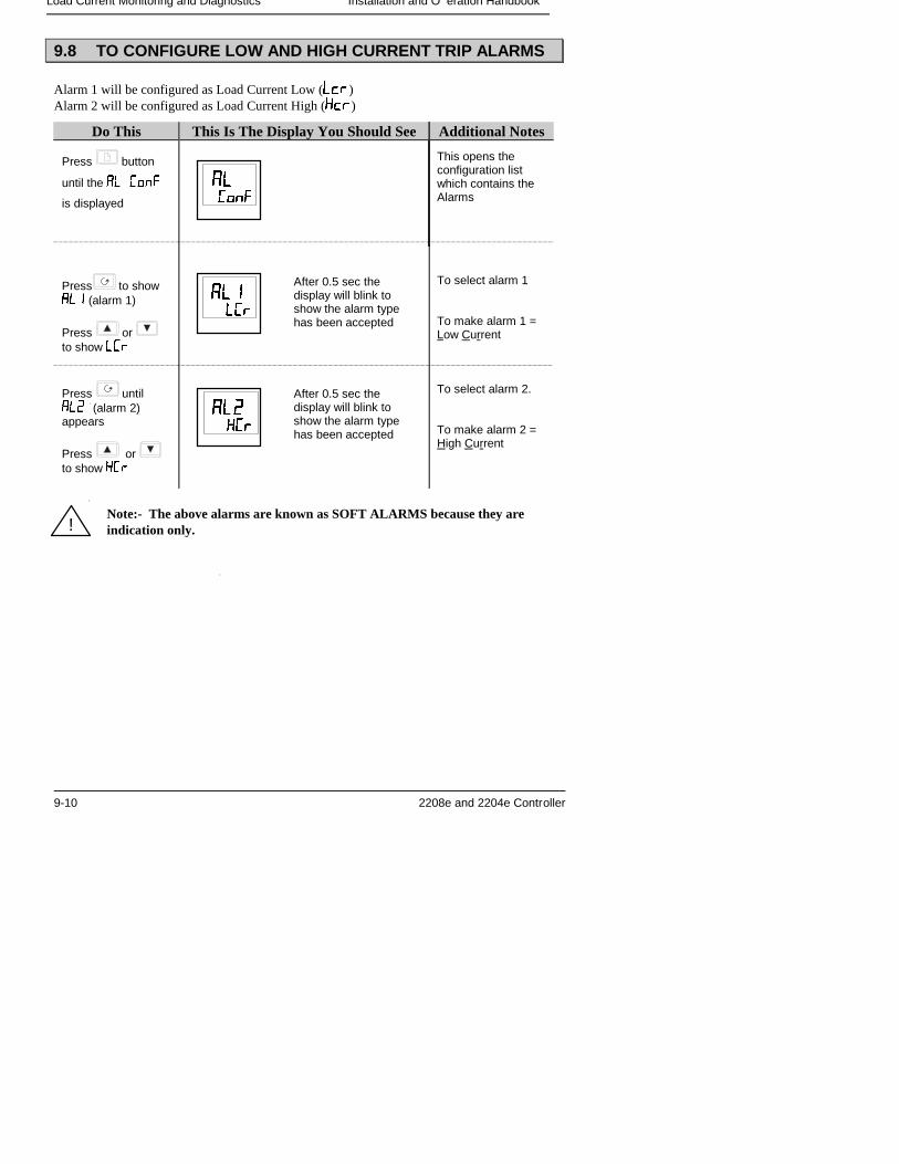
Load Current Monitoring and Diagnostics Installation and O eration Handbook
9-10 2208e and 2204e Controller
9.8 TO CONFIGURE LOW AND HIGH CURRENT TRIP ALARMS
Alarm 1 will be configured as Load Current Low (���)Alarm 2 will be configured as Load Current High (���)
Do This This Is The Display You Should See Additional Notes
Press button
until the �� ���
is displayed
This opens theconfiguration listwhich contains theAlarms
Press to show��� (alarm 1)
Press or to show � �
Press until��� (alarm 2)appears
Press or to show � �
To select alarm 1
To make alarm 1 =Low Current
To select alarm 2.
To make alarm 2 =High Current
Note:- The above alarms are known as SOFT ALARMS because they areindication only.
�� ��� ���
��� �� �
After 0.5 sec thedisplay will blink toshow the alarm typehas been accepted
����� �� �
After 0.5 sec thedisplay will blink toshow the alarm typehas been accepted
!
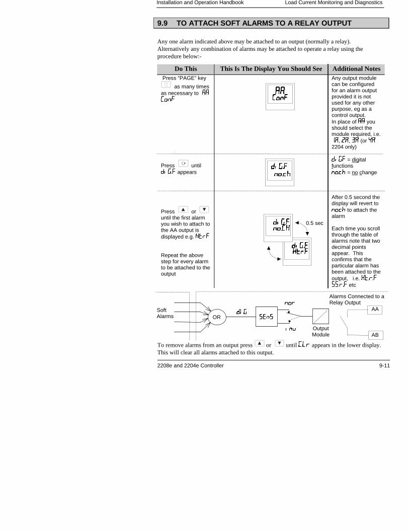
Installation and Operation Handbook Load Current Monitoring and Diagnostics
2208e and 2204e Controller 9-11
9.9 TO ATTACH SOFT ALARMS TO A RELAY OUTPUT
Any one alarm indicated above may be attached to an output (normally a relay).Alternatively any combination of alarms may be attached to operate a relay using theprocedure below:-
Do This This Is The Display You Should See Additional Notes Press “PAGE” key
as many timesas necessary to �� ���
Press until����� appears
Press or until the first alarmyou wish to attach tothe AA output isdisplayed e.g. ����
Repeat the abovestep for every alarmto be attached to theoutput
Any output modulecan be configuredfor an alarm outputprovided it is notused for any otherpurpose, eg as acontrol output.In place of �� youshould select themodule required, i.e.��, ��, � (or �2204 only)
�� � = digitalfunctions���� = no change
After 0.5 second thedisplay will revert to���� to attach thealarm
Each time you scrollthrough the table ofalarms note that twodecimal pointsappear. Thisconfirms that theparticular alarm hasbeen attached to theoutput, i.e. ������������ etc
To remove alarms from an output press or until �� appears in the lower display.This will clear all alarms attached to this output.
��������������������
���� ��� ���
����������������
������������� ���� �
0.5 sec
Alarms Connected to aRelay Output
�! ����
���
��" OutputModule
SoftAlarms OR
AA
AB
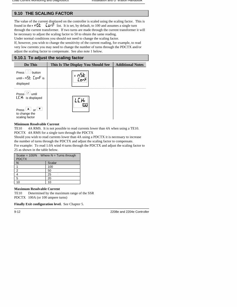
Load Current Monitoring and Diagnostics Installation and O eration Handbook
9-12 2208e and 2204e Controller
9.10 THE SCALING FACTOR
The value of the current displayed on the controller is scaled using the scaling factor. This isfound in the ��� ��� list. It is set, by default, to 100 and assumes a single turnthrough the current transformer. If two turns are made through the current transformer it willbe necessary to adjust the scaling factor to 50 to obtain the same reading.Under normal conditions you should not need to change the scaling factor.If, however, you wish to change the sensitivity of the current reading, for example, to readvery low currents you may need to change the number of turns through the PDCTX and/oradjust the scaling factor to compensate. See also note 1 below.
9.10.1 To adjust the scaling factor
Do This This Is The Display You Should See Additional Notes
Press button
until ���� ��� is
displayed
Press until� ��� is displayed
Press or to change thescaling factor
Minimum Resolvable CurrentTE10 4A RMS. It is not possible to read currents lower than 4A when using a TE10.PDCTX 4A RMS for a single turn through the PDCTXShould you wish to read currents lower than 4A using a PDCTX it is necessary to increasethe number of turns through the PDCTX and adjust the scaling factor to compensate.For example: To read 1.0A wind 4 turns through the PDCTX and adjust the scaling factor to25 as shown in the table below.
Scalar = 100/N Where N = Turns throughPDCTXN Scalar1 1002 504 255 2010 10
Maximum Resolvable CurrentTE10 Determined by the maximum range of the SSRPDCTX 100A (or 100 ampere turns)
Finally Exit configuration level. See Chapter 5.
� ��� �� ��� ���
������������
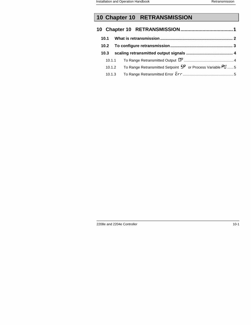
Installation and Operation Handbook Retransmission
2208e and 2204e Controller 10-1
10 Chapter 10 RETRANSMISSION
10 Chapter 10 RETRANSMISSION......................................1
10.1 What is retransmission ................................................................ 2
10.2 To configure retransmission....................................................... 3
10.3 scaling retransmitted output signals ......................................... 4
10.1.1 To Range Retransmitted Output �� ................................................4
10.1.2 To Range Retransmitted Setpoint �� or Process Variable �� ......5
10.1.3 To Range Retransmitted Error ���.................................................5
Retransmission Installation and O eration Handbook
10-2 2208e and 2204e Controller
10.1 WHAT IS RETRANSMISSION
The controller can be configured to generate an analogue output signal which represents aselected parameter.The parameters which can be configured for retransmission are:-
1. Process Variable2. Setpoint3. Error4. Control Output
The retransmission signal is available as 0-20mA, 4-20mA, 0-5V, 1-5V or 0-10V and isconnected to terminals 1A and 1B when module 1A is fitted as a DC module.
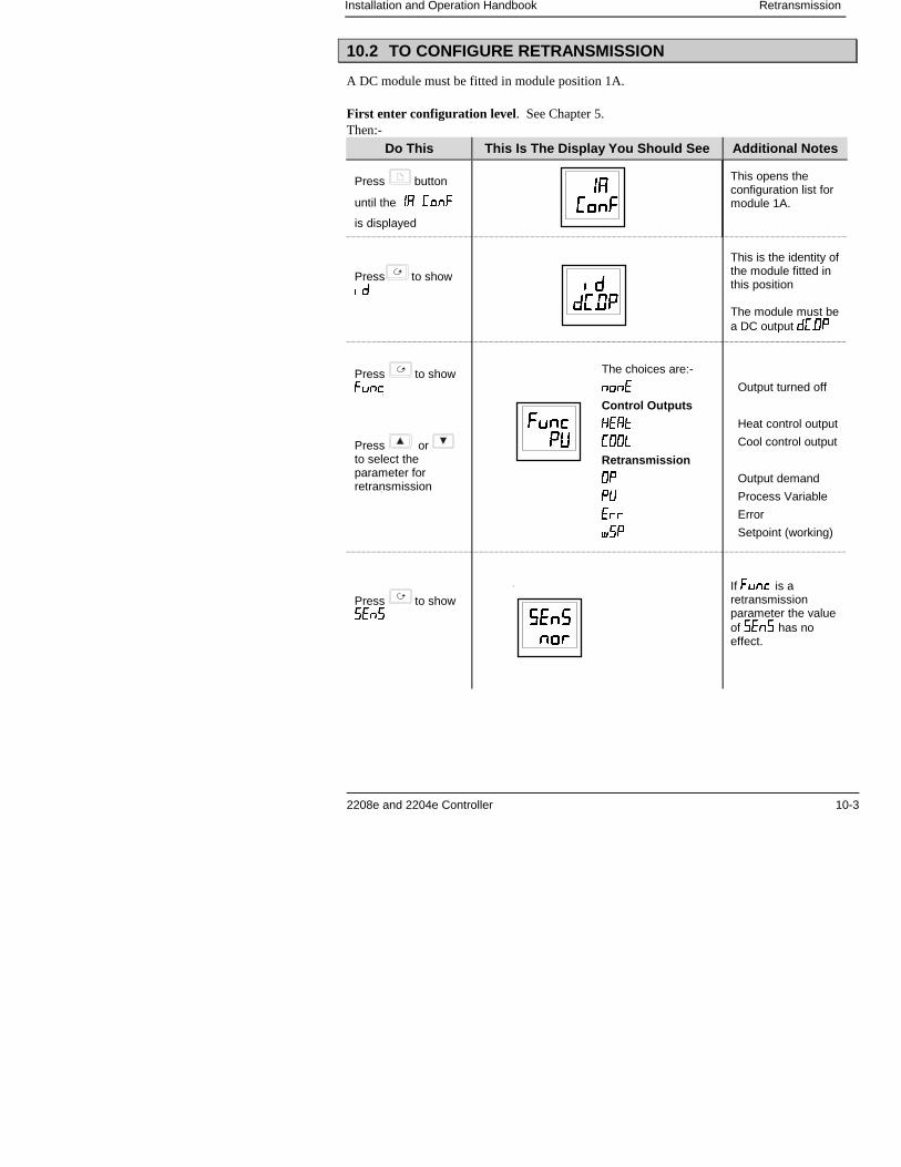
Installation and Operation Handbook Retransmission
2208e and 2204e Controller 10-3
10.2 TO CONFIGURE RETRANSMISSION
A DC module must be fitted in module position 1A.
First enter configuration level. See Chapter 5.Then:-
Do This This Is The Display You Should See Additional Notes
Press button
until the �� ����
is displayed
This opens theconfiguration list formodule 1A.
Press to show�
Press to show���
Press or to select theparameter forretransmission
Press to show ���
This is the identity ofthe module fitted inthis position
The module must bea DC output ����
If ��� is aretransmissionparameter the valueof ��� has noeffect.
������������
��������
��� �������
��������������
The choices are:-
���� Output turned off
Control Outputs
���� Heat control output
���� Cool control output
Retransmission
�� Output demand
�� Process Variable
��� Error
� � Setpoint (working)
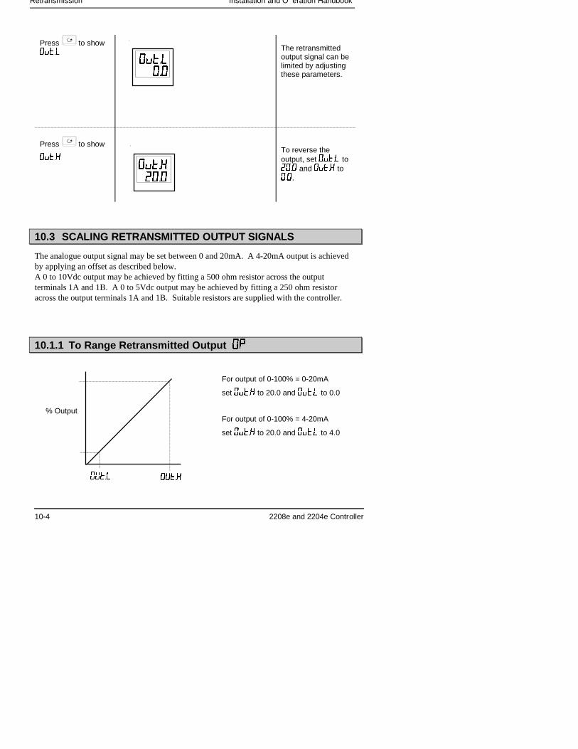
Retransmission Installation and O eration Handbook
10-4 2208e and 2204e Controller
Press to show�����
Press to show
�����
The retransmittedoutput signal can belimited by adjustingthese parameters.
To reverse theoutput, set ����� to���� and ����� to���.
10.3 SCALING RETRANSMITTED OUTPUT SIGNALS
The analogue output signal may be set between 0 and 20mA. A 4-20mA output is achievedby applying an offset as described below.A 0 to 10Vdc output may be achieved by fitting a 500 ohm resistor across the outputterminals 1A and 1B. A 0 to 5Vdc output may be achieved by fitting a 250 ohm resistoracross the output terminals 1A and 1B. Suitable resistors are supplied with the controller.
10.1.1 To Range Retransmitted Output ����
������������
��������������
����������
% Output
For output of 0-100% = 0-20mA
set ����� to 20.0 and ����� to 0.0
For output of 0-100% = 4-20mA
set ����� to 20.0 and ����� to 4.0
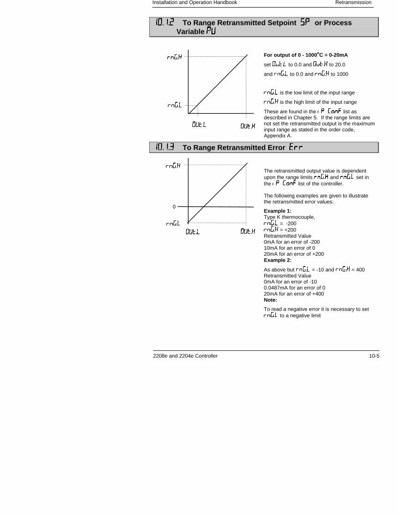
Installation and Operation Handbook Retransmission
2208e and 2204e Controller 10-5
�������� To Range Retransmitted Setpoint ���� or ProcessVariable ����
�������� To Range Retransmitted Error ������
For output of 0 - 1000 oC = 0-20mA
set ����� to 0.0 and ����� to 20.0
and ����� to 0.0 and ����� to 1000
����� is the low limit of the input range
����� is the high limit of the input range
These are found in the �� ��� list asdescribed in Chapter 5. If the range limits arenot set the retransmitted output is the maximuminput range as stated in the order code,Appendix A.
����������
�����
�����
The retransmitted output value is dependentupon the range limits ����� and ����� set inthe �� ��� list of the controller.
The following examples are given to illustratethe retransmitted error values:
Example 1:Type K thermocouple,����� = -200����� = +200Retransmitted Value0mA for an error of -20010mA for an error of 020mA for an error of +200Example 2:
As above but ����� = -10 and ����� = 400Retransmitted Value0mA for an error of -100.0487mA for an error of 020mA for an error of +400Note:
To read a negative error it is necessary to set����� to a negative limit
����������
�����
�����
0

Retransmission Installation and O eration Handbook
10-6 2208e and 2204e Controller
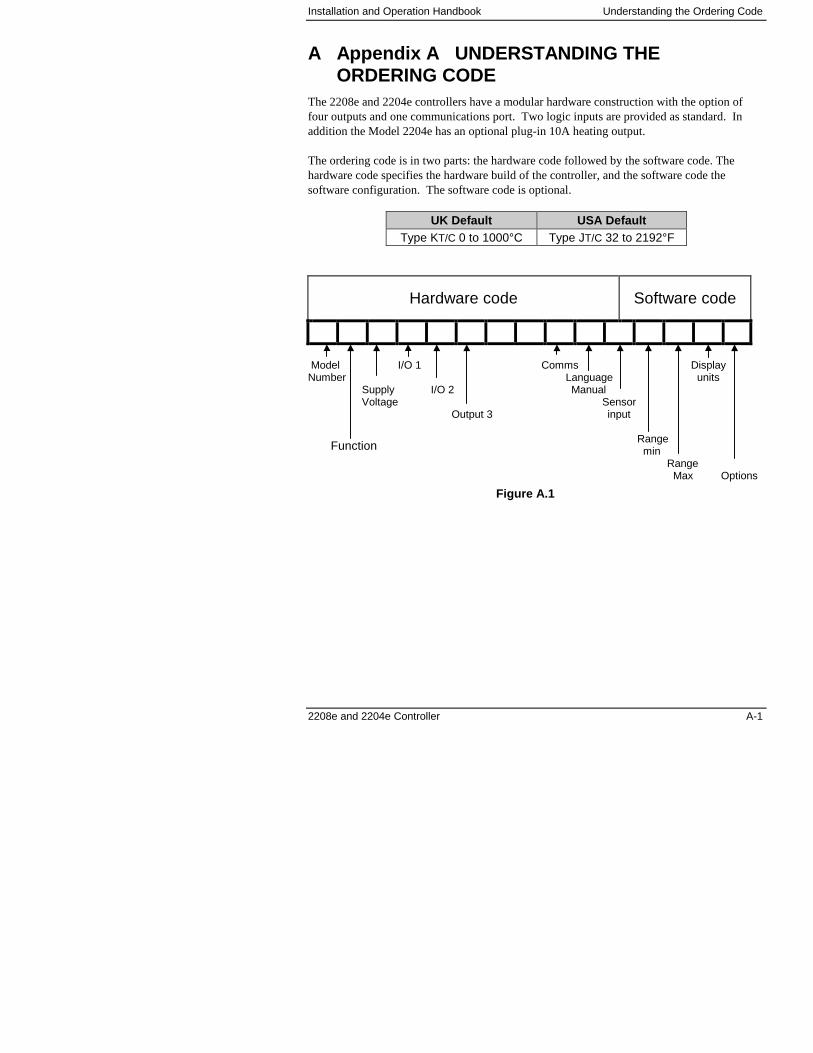
Installation and Operation Handbook Understanding the Ordering Code
2208e and 2204e Controller A-1
A Appendix A UNDERSTANDING THEORDERING CODE
The 2208e and 2204e controllers have a modular hardware construction with the option offour outputs and one communications port. Two logic inputs are provided as standard. Inaddition the Model 2204e has an optional plug-in 10A heating output.
The ordering code is in two parts: the hardware code followed by the software code. Thehardware code specifies the hardware build of the controller, and the software code thesoftware configuration. The software code is optional.
UK Default USA DefaultType KT/C 0 to 1000°C Type JT/C 32 to 2192°F
Hardware code Software code
Model I/O 1 Comms DisplayNumber Language units
Supply I/O 2 ManualVoltage Sensor
Output 3 input
Rangemin
RangeMax Options
Function
Figure A.1
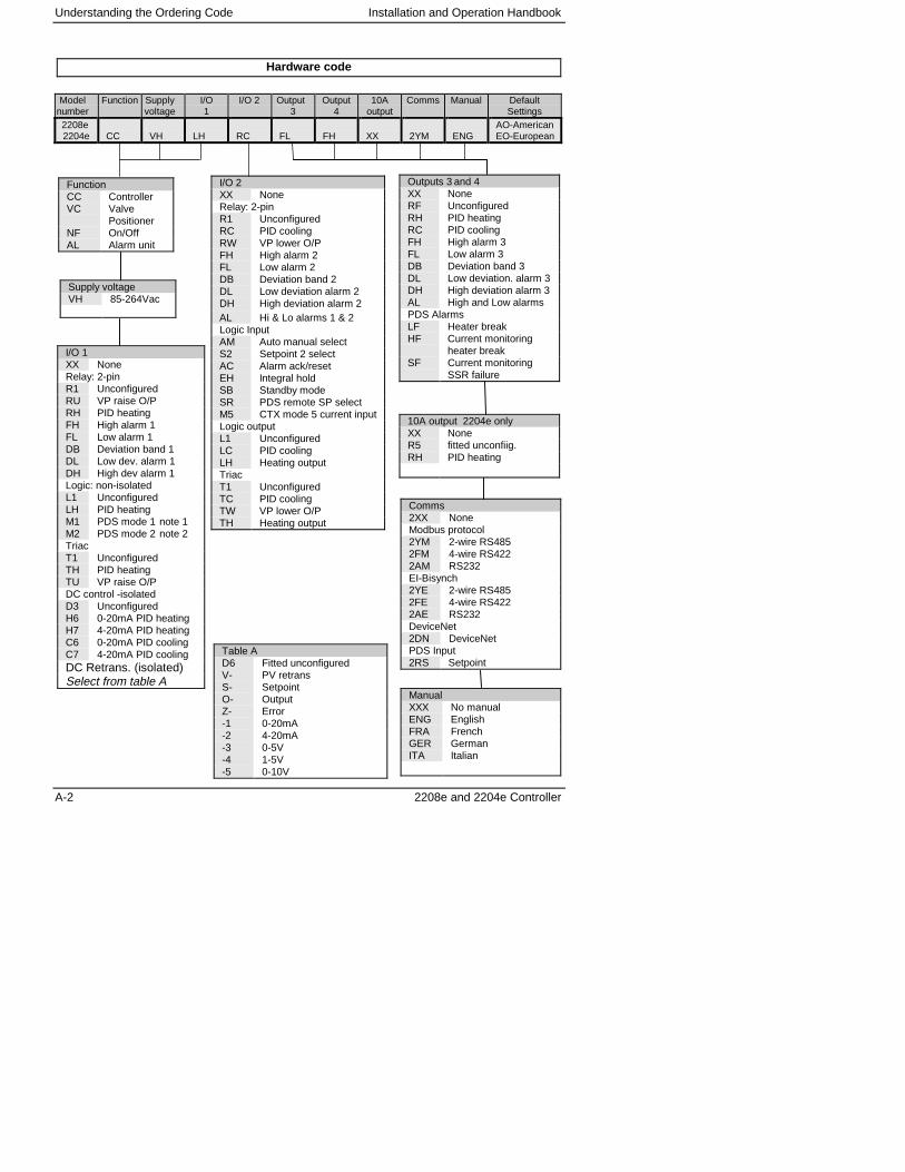
Understanding the Ordering Code Installation and Operation Handbook
A-2 2208e and 2204e Controller
Hardware code
Modelnumber
Function Supplyvoltage
I/O1
I/O 2 Output3
Output4
10Aoutput
Comms Manual DefaultSettings
2208e2204e CC VH LH RC FL FH XX 2YM ENG
AO-AmericanEO-European
Supply voltageVH 85-264Vac
FunctionCC ControllerVC Valve
PositionerNF On/OffAL Alarm unit
10A output 2204e onlyXX NoneR5 fitted unconfiig.RH PID heating
ManualXXX No manualENG EnglishFRA FrenchGER GermanITA Italian
I/O 1XX NoneRelay: 2-pinR1 UnconfiguredRU VP raise O/PRH PID heatingFH High alarm 1FL Low alarm 1DB Deviation band 1DL Low dev. alarm 1DH High dev alarm 1Logic: non-isolatedL1 UnconfiguredLH PID heatingM1 PDS mode 1 note 1M2 PDS mode 2 note 2TriacT1 UnconfiguredTH PID heatingTU VP raise O/PDC control -isolatedD3 UnconfiguredH6 0-20mA PID heatingH7 4-20mA PID heatingC6 0-20mA PID coolingC7 4-20mA PID coolingDC Retrans. (isolated)Select from table A
Table AD6 Fitted unconfiguredV- PV retransS- SetpointO- OutputZ- Error-1 0-20mA-2 4-20mA-3 0-5V-4 1-5V-5 0-10V
I/O 2XX NoneRelay: 2-pinR1 UnconfiguredRC PID coolingRW VP lower O/PFH High alarm 2FL Low alarm 2DB Deviation band 2DL Low deviation alarm 2DH High deviation alarm 2AL Hi & Lo alarms 1 & 2Logic InputAM Auto manual selectS2 Setpoint 2 selectAC Alarm ack/resetEH Integral holdSB Standby modeSR PDS remote SP selectM5 CTX mode 5 current inputLogic outputL1 UnconfiguredLC PID coolingLH Heating outputTriacT1 UnconfiguredTC PID coolingTW VP lower O/PTH Heating output
Outputs 3 and 4XX NoneRF UnconfiguredRH PID heatingRC PID coolingFH High alarm 3FL Low alarm 3DB Deviation band 3DL Low deviation. alarm 3DH High deviation alarm 3AL High and Low alarmsPDS AlarmsLF Heater breakHF Current monitoring
heater breakSF Current monitoring
SSR failure
Comms2XX NoneModbus protocol2YM 2-wire RS4852FM 4-wire RS4222AM RS232EI-Bisynch2YE 2-wire RS4852FE 4-wire RS4222AE RS232DeviceNet2DN DeviceNetPDS Input2RS Setpoint
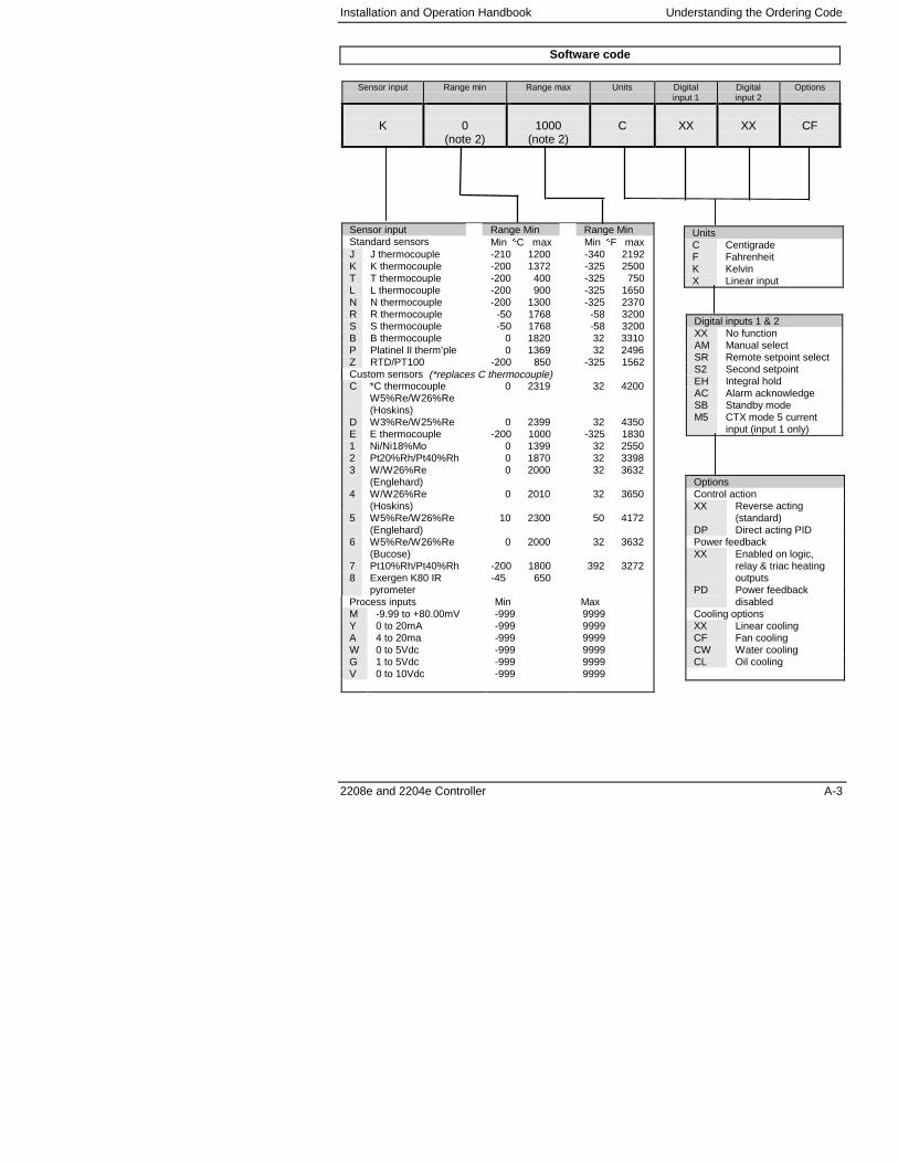
Installation and Operation Handbook Understanding the Ordering Code
2208e and 2204e Controller A-3
Software code
Sensor input Range min Range max Units Digitalinput 1
Digitalinput 2
Options
K 0(note 2)
1000(note 2)
C XX XX CF
Sensor input Range Min Range MinStandard sensors Min �C max Min �F maxJ J thermocouple -210 1200 -340 2192K K thermocouple -200 1372 -325 2500T T thermocouple -200 400 -325 750L L thermocouple -200 900 -325 1650N N thermocouple -200 1300 -325 2370R R thermocouple -50 1768 -58 3200S S thermocouple -50 1768 -58 3200B B thermocouple 0 1820 32 3310P Platinel II therm’ple 0 1369 32 2496Z RTD/PT100 -200 850 -325 1562Custom sensors (*replaces C thermocouple)C *C thermocouple
W5%Re/W26%Re(Hoskins)
0 2319 32 4200
D W3%Re/W25%Re 0 2399 32 4350E E thermocouple -200 1000 -325 18301 Ni/Ni18%Mo 0 1399 32 25502 Pt20%Rh/Pt40%Rh 0 1870 32 33983 W/W26%Re
(Englehard) 0 2000 32 3632
4 W/W26%Re(Hoskins)
0 2010 32 3650
5 W5%Re/W26%Re(Englehard)
10 2300 50 4172
6 W5%Re/W26%Re(Bucose)
0 2000 32 3632
7 Pt10%Rh/Pt40%Rh -200 1800 392 32728 Exergen K80 IR
pyrometer-45 650
Process inputs Min MaxM -9.99 to +80.00mV -999 9999Y 0 to 20mA -999 9999A 4 to 20ma -999 9999W 0 to 5Vdc -999 9999G 1 to 5Vdc -999 9999V 0 to 10Vdc -999 9999
OptionsControl actionXX Reverse acting
(standard)DP Direct acting PIDPower feedbackXX Enabled on logic,
relay & triac heatingoutputs
PD Power feedbackdisabled
Cooling optionsXX Linear coolingCF Fan coolingCW Water coolingCL Oil cooling
Digital inputs 1 & 2XX No functionAM Manual selectSR Remote setpoint selectS2 Second setpointEH Integral holdAC Alarm acknowledgeSB Standby modeM5 CTX mode 5 current
input (input 1 only)
UnitsC CentigradeF FahrenheitK KelvinX Linear input
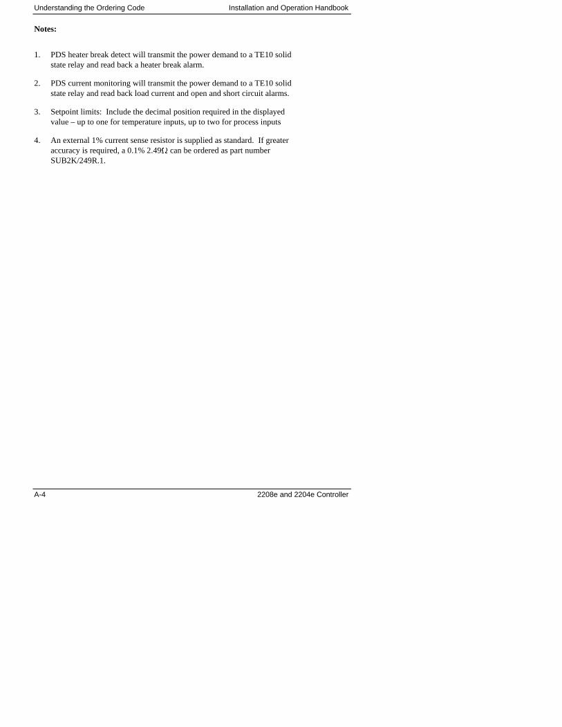
Understanding the Ordering Code Installation and Operation Handbook
A-4 2208e and 2204e Controller
Notes:
1. PDS heater break detect will transmit the power demand to a TE10 solidstate relay and read back a heater break alarm.
2. PDS current monitoring will transmit the power demand to a TE10 solidstate relay and read back load current and open and short circuit alarms.
3. Setpoint limits: Include the decimal position required in the displayedvalue – up to one for temperature inputs, up to two for process inputs
4. An external 1% current sense resistor is supplied as standard. If greateraccuracy is required, a 0.1% 2.49� can be ordered as part numberSUB2K/249R.1.
Installation and Operation Handbook Safety Information
2208e and 2204e Controller B-1
B Appendix B SAFETY and EMC INFORMATIONThis controller is intended for industrial temperature and process control applications when itwill meet the requirements of the European Directives on Safety and EMC. Use in otherapplications, or failure to observe the installation instructions of this handbook may impairsafety or EMC. The installer must ensure the safety and EMC of any particular installation.
Safety
This controller complies with the European Low Voltage Directive 73/23/EEC, amended by93/68/EEC, by the application of the safety standard EN 61010.
Electromagnetic compatibility
This controller conforms with the essential protection requirements of the EMC Directive89/336/EEC, amended by 93/68/EEC, by the application of a Technical Construction File.This instrument satisfies the general requirements of the industrial environment defined in EN50081-2 and EN 50082-2. For more information on product compliance refer to the TechnicalConstruction File.
GENERAL
The information contained in this manual is subject to change without notice. While everyeffort has been made to ensure the accuracy of the information, your supplier shall not be heldliable for errors contained herein.
Unpacking and storage
The packaging should contain an instrument mounted in its sleeve, two mounting brackets forpanel installation and this operating book. Certain ranges are supplied with an input adapter.If on receipt, the packaging or the instrument are damaged, do not install the product butcontact your supplier.If the instrument is to be stored before use, protect from humidity and dust in an ambienttemperature range of -30oC to +75oC.
SERVICE AND REPAIR
This controller has no user serviceable parts. Contact your supplier for repair.
Caution: Charged capacitors
Before removing an instrument from its sleeve, disconnect the supply and wait at least twominutes to allow capacitors to discharge. It may be convenient to partially withdraw theinstrument from the sleeve, then pause before completing the removal. In any case, avoidtouching the exposed electronics of an instrument when withdrawing it from the sleeve.Failure to observe these precautions may cause damage to components of the instrument orsome discomfort to the user.
Safety Information Installation and Operation Handbook
B-2 2208e and 2204e Controller
Electrostatic discharge precautions
When the controller is removed from its sleeve, some of the exposed electronic componentsare vulnerable to damage by electrostatic discharge from someone handling the controller. Toavoid this, before handling the unplugged controller discharge yourself to ground.
Cleaning
Do not use water or water based products to clean labels or they will become illegible.Isopropyl alcohol may be used to clean labels. A mild soap solution may be used to cleanother exterior surfaces of the product.
INSTALLATION SAFETY REQUIREMENTS
Safety Symbols
Various symbols are used on the instrument, they have the following meaning:
Caution, (refer to theaccompanying documents)
Functional earth(ground) terminal!
The functional earth connection is not required for safety purposes but is used to ground RFIfilters.
Personnel
Installation must only be carried out by qualified personnel.
Enclosure of live parts
To prevent hands or metal tools touching parts that may be electrically live, the controllermust be installed in an enclosure.
Caution: Live sensors
The logic and PDS outputs are electrically connected to the main PV input, (thermocoupleetc.). If the temperature sensor is connected directly to an electrical heating element then thesenon-isolated inputs and outputs will also be live. The controller is designed to operate underthese conditions. However you must ensure that this will not damage other equipmentconnected to these inputs and outputs and that service personnel do not touch connections tothese I/O while they are live. With a live sensor, all cables, connectors and switches forconnecting the sensor and non-isolated inputs and outputs must be mains rated.
Installation and Operation Handbook Safety Information
2208e and 2204e Controller B-3
Wiring
It is important to connect the controller in accordance with the wiring data given in thishandbook. Take particular care not to connect AC supplies to the low voltage sensor input orother low level inputs and outputs. Only use copper conductors for connections, (exceptthermocouple). Ensure that the wiring of installations comply with all local wiringregulations. For example in the UK, use the latest version of the IEE wiring regulations,(BS7671). In the USA, use NEC Class 1 wiring methods.
Power Isolation
The installation must include a power isolating switch or circuit breaker that disconnects allcurrent carrying conductors. The device should be mounted in close proximity to the controller,within easy reach of the operator and marked as the disconnecting device for the instrument.
Earth leakage current
Due to RFI Filtering there is an earth leakage current of less than 0.5mA. This may affect thedesign of an installation of multiple controllers protected by Residual Current Device, (RCD)or Ground Fault Detector, (GFD) type circuit breakers.
Overcurrent protection
To protect the internal PCB tracking within the controller against excess currents, the ACpower supply to the controller and power outputs must be wired through the fuse or circuitbreaker specified in the technical specification.
Voltage rating
The maximum continuous voltage applied between any connection to ground must not exceed264Vac.
The controller should not be wired to a three phase supply with an unearthed star connection.Under fault conditions such a supply could rise above 264Vac with respect to ground and theproduct would not be safe.
Voltage transients across the power supply connections, and between the power supply andground, must not exceed 2.5kV. Where occasional voltage transients over 2.5kV are expectedor measured, the power installation to both the instrument supply and load circuits shouldinclude a transient limiting device.
These units will typically include gas discharge tubes and metal oxide varistors that limit andcontrol voltage transients on the supply line due to lightning strikes or inductive loadswitching. Devices are available in a range of energy ratings and should be selected to suitconditions at the installation.
Safety Information Installation and Operation Handbook
B-4 2208e and 2204e Controller
Conductive pollution
Electrically conductive pollution must be excluded from the cabinet in which the controller ismounted. For example, carbon dust is a form of electrically conductive pollution. To secure asuitable atmosphere, install an air filter to the air intake of the cabinet. Where condensation is likely,for example at low temperatures, include a thermostatically controlled heater in the cabinet.
Grounding of the temperature sensor shield
In some installations it is common practice to replace the temperature sensor while thecontroller is still powered up. Under these conditions, as additional protection against electricshock, we recommend that the shield of the temperature sensor is grounded. Do not rely ongrounding through the framework of the machine.
Over-temperature protection
When designing any control system it is essential to consider what will happen if any part ofthe system should fail. In temperature control applications the primary danger is that theheating will remain constantly on. Apart from spoiling the product, this could damage anyprocess machinery being controlled, or even cause a fire.
Reasons why the heating might remain constantly on include:
� the temperature sensor becoming detached from the process
� thermocouple wiring becoming short circuit;
� the controller failing with its heating output constantly on
� an external valve or contactor sticking in the heating condition
� the controller setpoint set too high.
Where damage or injury is possible, we recommend fitting a separate over-temperatureprotection unit, with an independent temperature sensor, which will isolate the heating circuit.
Please note that the alarm relays within the controller will not give protection under all failureconditions.
Installation and Operation Handbook Safety Information
2208e and 2204e Controller B-5
INSTALLATION REQUIREMENTS FOR EMC
To ensure compliance with the European EMC directive certain installation precautions arenecessary as follows:
� For general guidance refer to EMC Installation Guide, HA025464.
� When using relay or triac outputs it may be necessary to fit a filter suitable for suppressingthe conducted emissions. The filter requirements will depend on the type of load. Fortypical applications we recommend Schaffner FN321 or FN612.
� If the unit is used in table top equipment which is plugged into a standard power socket,then it is likely that compliance to the commercial and light industrial emissions standardis required. In this case to meet the conducted emissions requirement, a suitable mainsfilter should be installed. We recommend Schaffner types FN321 and FN612.
Routing of wires
To minimise the pick-up of electrical noise, the low voltage DC connections and the sensorinput wiring should be routed away from high-current power cables. Where it is impracticalto do this, use shielded cables with the shield grounded at both ends. In general keep cablelengths to a minimum.
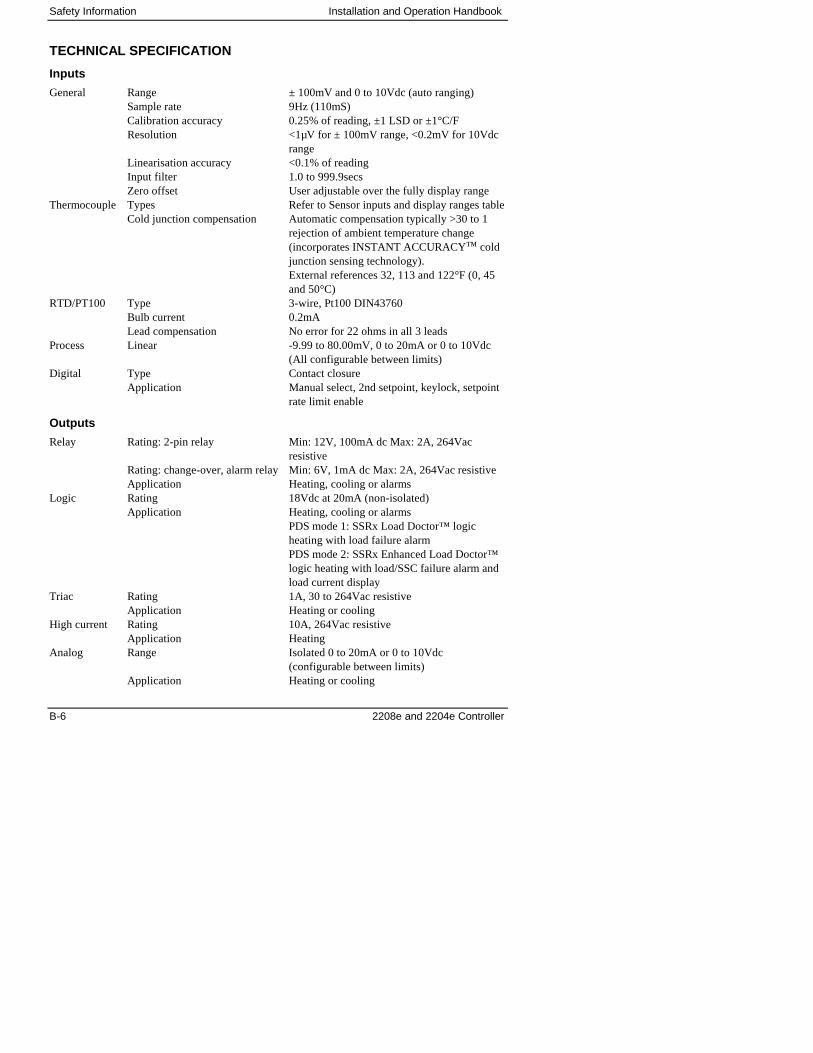
Safety Information Installation and Operation Handbook
B-6 2208e and 2204e Controller
TECHNICAL SPECIFICATION
Inputs
General Range ± 100mV and 0 to 10Vdc (auto ranging)Sample rate 9Hz (110mS)Calibration accuracy 0.25% of reading, ±1 LSD or ±1°C/FResolution <1µV for ± 100mV range, <0.2mV for 10Vdc
rangeLinearisation accuracy <0.1% of readingInput filter 1.0 to 999.9secsZero offset User adjustable over the fully display range
Thermocouple Types Refer to Sensor inputs and display ranges tableCold junction compensation Automatic compensation typically >30 to 1
rejection of ambient temperature change(incorporates INSTANT ACCURACY™ coldjunction sensing technology).External references 32, 113 and 122°F (0, 45and 50°C)
RTD/PT100 Type 3-wire, Pt100 DIN43760Bulb current 0.2mALead compensation No error for 22 ohms in all 3 leads
Process Linear -9.99 to 80.00mV, 0 to 20mA or 0 to 10Vdc(All configurable between limits)
Digital Type Contact closureApplication Manual select, 2nd setpoint, keylock, setpoint
rate limit enable
Outputs
Relay Rating: 2-pin relay Min: 12V, 100mA dc Max: 2A, 264Vacresistive
Rating: change-over, alarm relay Min: 6V, 1mA dc Max: 2A, 264Vac resistiveApplication Heating, cooling or alarms
Logic Rating 18Vdc at 20mA (non-isolated)Application Heating, cooling or alarms
PDS mode 1: SSRx Load Doctor™ logicheating with load failure alarmPDS mode 2: SSRx Enhanced Load Doctor™logic heating with load/SSC failure alarm andload current display
Triac Rating 1A, 30 to 264Vac resistiveApplication Heating or cooling
High current Rating 10A, 264Vac resistiveApplication Heating
Analog Range Isolated 0 to 20mA or 0 to 10Vdc(configurable between limits)
Application Heating or cooling
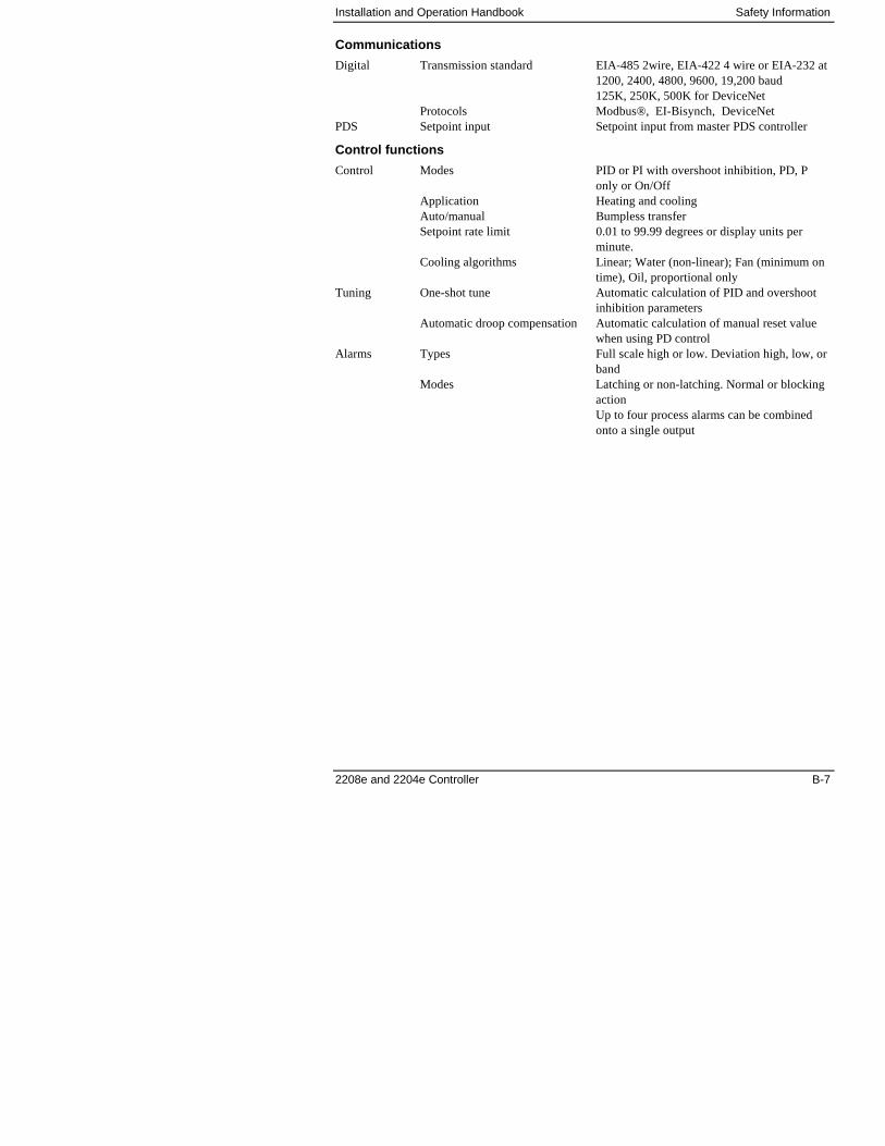
Installation and Operation Handbook Safety Information
2208e and 2204e Controller B-7
Communications
Digital Transmission standard EIA-485 2wire, EIA-422 4 wire or EIA-232 at1200, 2400, 4800, 9600, 19,200 baud125K, 250K, 500K for DeviceNet
Protocols Modbus®, EI-Bisynch, DeviceNetPDS Setpoint input Setpoint input from master PDS controller
Control functions
Control Modes PID or PI with overshoot inhibition, PD, Ponly or On/Off
Application Heating and coolingAuto/manual Bumpless transferSetpoint rate limit 0.01 to 99.99 degrees or display units per
minute.Cooling algorithms Linear; Water (non-linear); Fan (minimum on
time), Oil, proportional onlyTuning One-shot tune Automatic calculation of PID and overshoot
inhibition parametersAutomatic droop compensation Automatic calculation of manual reset value
when using PD controlAlarms Types Full scale high or low. Deviation high, low, or
bandModes Latching or non-latching. Normal or blocking
actionUp to four process alarms can be combinedonto a single output
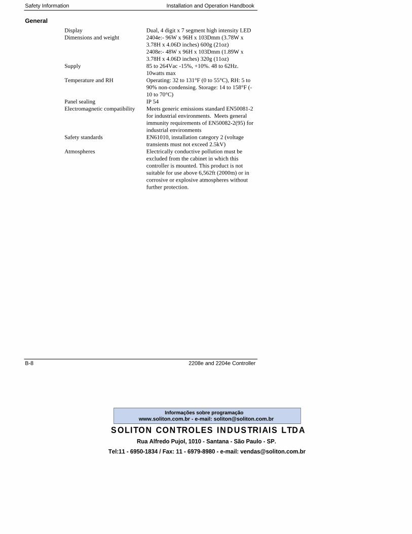
Safety Information Installation and Operation Handbook
B-8 2208e and 2204e Controller
General
Display Dual, 4 digit x 7 segment high intensity LEDDimensions and weight 2404e:- 96W x 96H x 103Dmm (3.78W x
3.78H x 4.06D inches) 600g (21oz)2408e:- 48W x 96H x 103Dmm (1.89W x3.78H x 4.06D inches) 320g (11oz)
Supply 85 to 264Vac -15%, +10%. 48 to 62Hz.10watts max
Temperature and RH Operating: 32 to 131°F (0 to 55°C), RH: 5 to90% non-condensing. Storage: 14 to 158°F (-10 to 70°C)
Panel sealing IP 54Electromagnetic compatibility Meets generic emissions standard EN50081-2
for industrial environments. Meets generalimmunity requirements of EN50082-2(95) forindustrial environments
Safety standards EN61010, installation category 2 (voltagetransients must not exceed 2.5kV)
Atmospheres Electrically conductive pollution must beexcluded from the cabinet in which thiscontroller is mounted. This product is notsuitable for use above 6,562ft (2000m) or incorrosive or explosive atmospheres withoutfurther protection.
Rua Alfredo Pujol, 1010 - Santana - São Paulo - SP.
SOLITON CONTROLES INDUSTRIAIS LTDA
Tel:11 - 6950-1834 / Fax: 11 - 6979-8980 - e-mail: [email protected]
www.soliton.com.br - e-mail: [email protected]ções sobre programação