MODELLING OF EXCAVATIONS USING PLAXIS · PLAXIS FINITE ELEMENT CODE FOR SOIL AND ROCK ANALYSES...
28
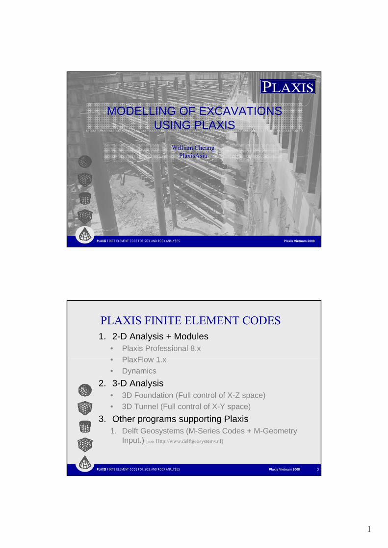
1 MODELLING OF EXCAVATIONS USING PLAXIS William Cheang PlaxisAsia PLAXIS FINITE ELEMENT CODE FOR SOIL AND ROCK ANALYSES Plaxis Vietnam 2008 PLAXIS FINITE ELEMENT CODES 1. 2-D Analysis + Modules • Plaxis Professional 8.x • PlaxFlow 1 x • PlaxFlow 1.x • Dynamics 2. 3-D Analysis • 3D Foundation (Full control of X-Z space) • 3D Tunnel (Full control of X-Y space) 3 Other programs supporting Plaxis PLAXIS FINITE ELEMENT CODE FOR SOIL AND ROCK ANALYSES Plaxis Vietnam 2008 2 3. Other programs supporting Plaxis 1. Delft Geosystems (M-Series Codes + M-Geometry Input.) [see Http://www.delftgeosystems.nl]
Transcript of MODELLING OF EXCAVATIONS USING PLAXIS · PLAXIS FINITE ELEMENT CODE FOR SOIL AND ROCK ANALYSES...
1
MODELLING OF EXCAVATIONSUSING PLAXIS
William CheangPlaxisAsia
PLAXIS FINITE ELEMENT CODE FOR SOIL AND ROCK ANALYSES Plaxis Vietnam 2008
PLAXIS FINITE ELEMENT CODES1. 2-D Analysis + Modules
• Plaxis Professional 8.x• PlaxFlow 1 x• PlaxFlow 1.x• Dynamics
2. 3-D Analysis• 3D Foundation (Full control of X-Z space)• 3D Tunnel (Full control of X-Y space)
3 Other programs supporting Plaxis
PLAXIS FINITE ELEMENT CODE FOR SOIL AND ROCK ANALYSES Plaxis Vietnam 2008 2
3. Other programs supporting Plaxis1. Delft Geosystems (M-Series Codes + M-Geometry
Input.) [see Http://www.delftgeosystems.nl]
2
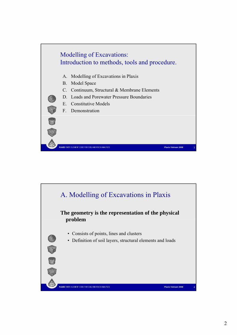
Modelling of Excavations: Introduction to methods, tools and procedure.
A. Modelling of Excavations in PlaxisB. Model SpaceC. Continuum, Structural & Membrane ElementsD. Loads and Porewater Pressure BoundariesE. Constitutive ModelsF. Demonstration
PLAXIS FINITE ELEMENT CODE FOR SOIL AND ROCK ANALYSES Plaxis Vietnam 2008 3
A. Modelling of Excavations in Plaxis
The geometry is the representation of the physical problemproblem
• Consists of points, lines and clusters• Definition of soil layers, structural elements and loads
PLAXIS FINITE ELEMENT CODE FOR SOIL AND ROCK ANALYSES Plaxis Vietnam 2008 4
3
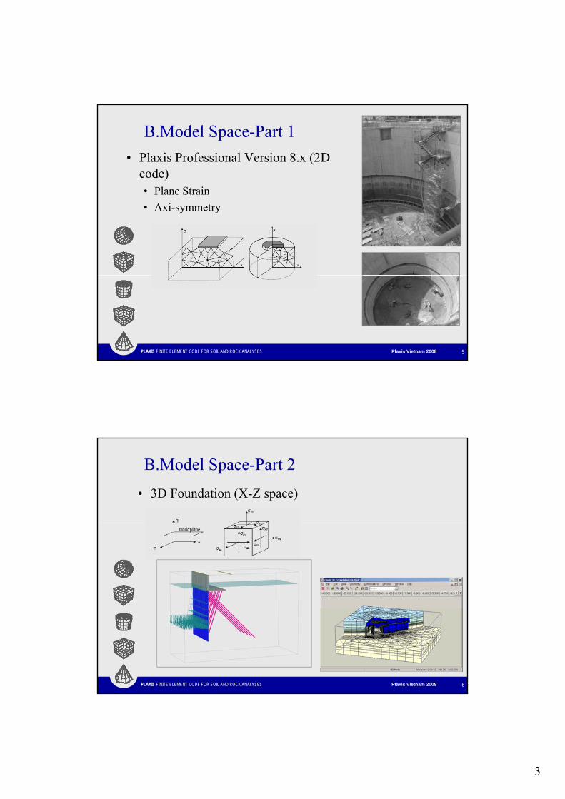
B.Model Space-Part 1• Plaxis Professional Version 8.x (2D
code)• Plane Strain• Plane Strain• Axi-symmetry
PLAXIS FINITE ELEMENT CODE FOR SOIL AND ROCK ANALYSES Plaxis Vietnam 2008 5
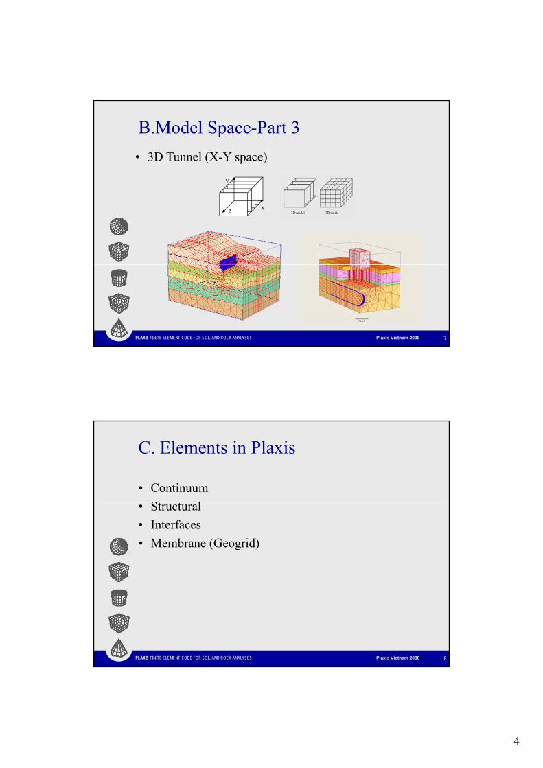
B.Model Space-Part 2• 3D Foundation (X-Z space)
PLAXIS FINITE ELEMENT CODE FOR SOIL AND ROCK ANALYSES Plaxis Vietnam 2008 6
4
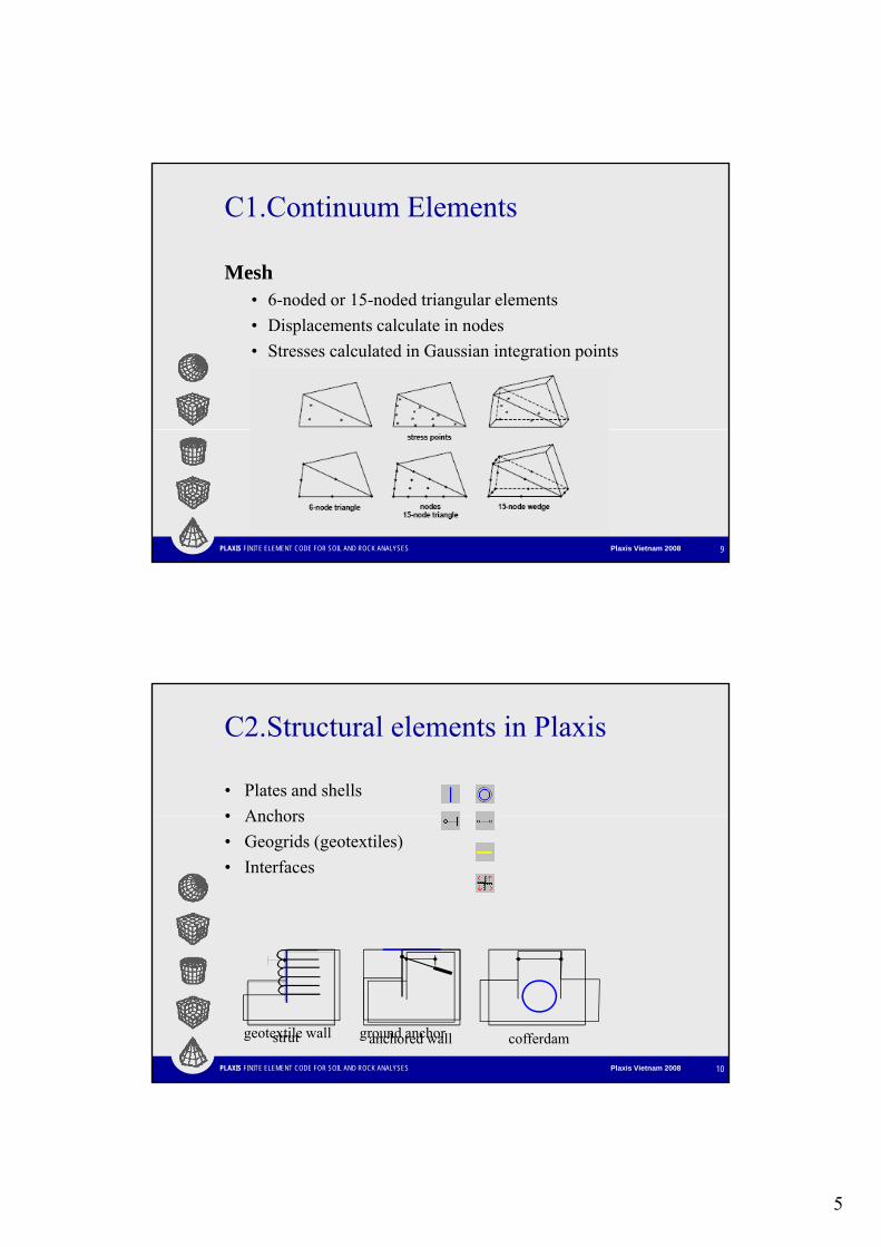
B.Model Space-Part 3• 3D Tunnel (X-Y space)
yy
xz
PLAXIS FINITE ELEMENT CODE FOR SOIL AND ROCK ANALYSES Plaxis Vietnam 2008 7
C. Elements in Plaxis
• ContinuumS l• Structural
• Interfaces• Membrane (Geogrid)
PLAXIS FINITE ELEMENT CODE FOR SOIL AND ROCK ANALYSES Plaxis Vietnam 2008 8
5
C1.Continuum Elements
Mesh6 d d 15 d d t i l l t• 6-noded or 15-noded triangular elements
• Displacements calculate in nodes• Stresses calculated in Gaussian integration points
PLAXIS FINITE ELEMENT CODE FOR SOIL AND ROCK ANALYSES Plaxis Vietnam 2008 9
C2.Structural elements in Plaxis
• Plates and shells • Anchors• Anchors• Geogrids (geotextiles)• Interfaces
PLAXIS FINITE ELEMENT CODE FOR SOIL AND ROCK ANALYSES Plaxis Vietnam 2008 10
strut anchored wall cofferdamgeotextile wall ground anchor
6
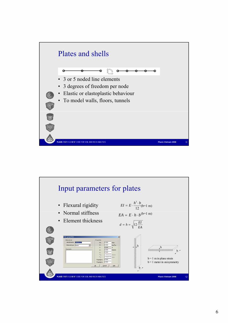
Plates and shells
• 3 or 5 noded line elements• 3 degrees of freedom per node• Elastic or elastoplastic behaviour• To model walls, floors, tunnels
PLAXIS FINITE ELEMENT CODE FOR SOIL AND ROCK ANALYSES Plaxis Vietnam 2008 11
Input parameters for plates
• Flexural rigidity (b=1 m)
N l iff12
3 bhEEI ⋅⋅=
• Normal stiffness (b=1 m)
• Element thicknessbhEEA ⋅⋅=
EAEIhd 12==
h
PLAXIS FINITE ELEMENT CODE FOR SOIL AND ROCK ANALYSES Plaxis Vietnam 2008 12
b
h hb
b = 1 m in plane strainb = 1 meter in axisymmetry
7
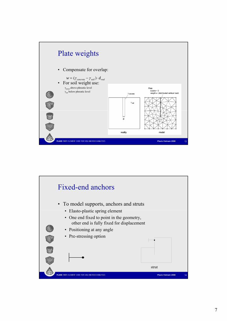
Plate weights
• Compensate for overlap:
• For soil weight use:γunsat above phreatic levelγsat below phreatic level
realsoilconcrete dw ⋅−= )( γγ
PLAXIS FINITE ELEMENT CODE FOR SOIL AND ROCK ANALYSES Plaxis Vietnam 2008 13
Fixed-end anchors
• To model supports, anchors and strutsEl t l ti i l t• Elasto-plastic spring element
• One end fixed to point in the geometry,other end is fully fixed for displacement
• Positioning at any angle• Pre-stressing option
PLAXIS FINITE ELEMENT CODE FOR SOIL AND ROCK ANALYSES Plaxis Vietnam 2008 14
strut
8
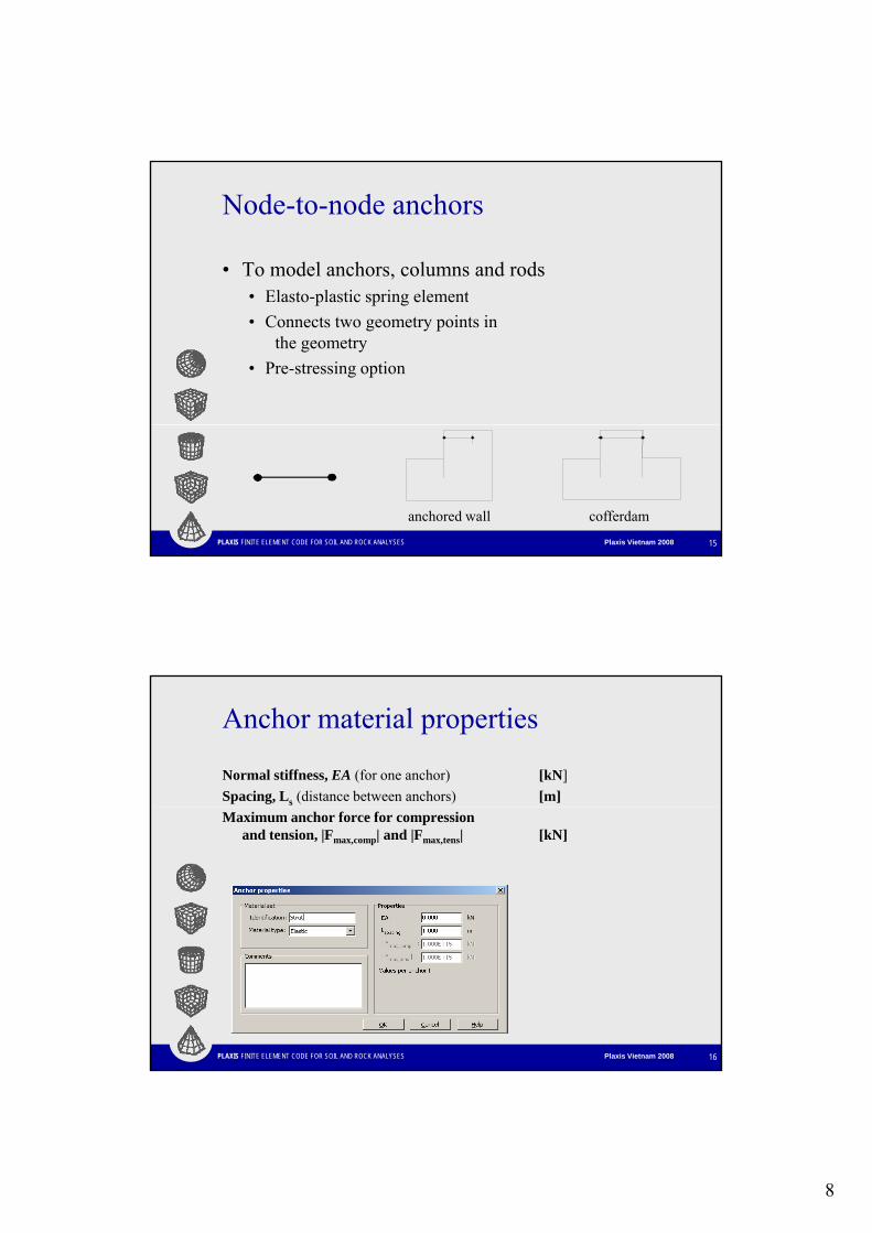
Node-to-node anchors
• To model anchors, columns and rodsEl t l ti i l t• Elasto-plastic spring element
• Connects two geometry points in the geometry
• Pre-stressing option
PLAXIS FINITE ELEMENT CODE FOR SOIL AND ROCK ANALYSES Plaxis Vietnam 2008 15
anchored wall cofferdam
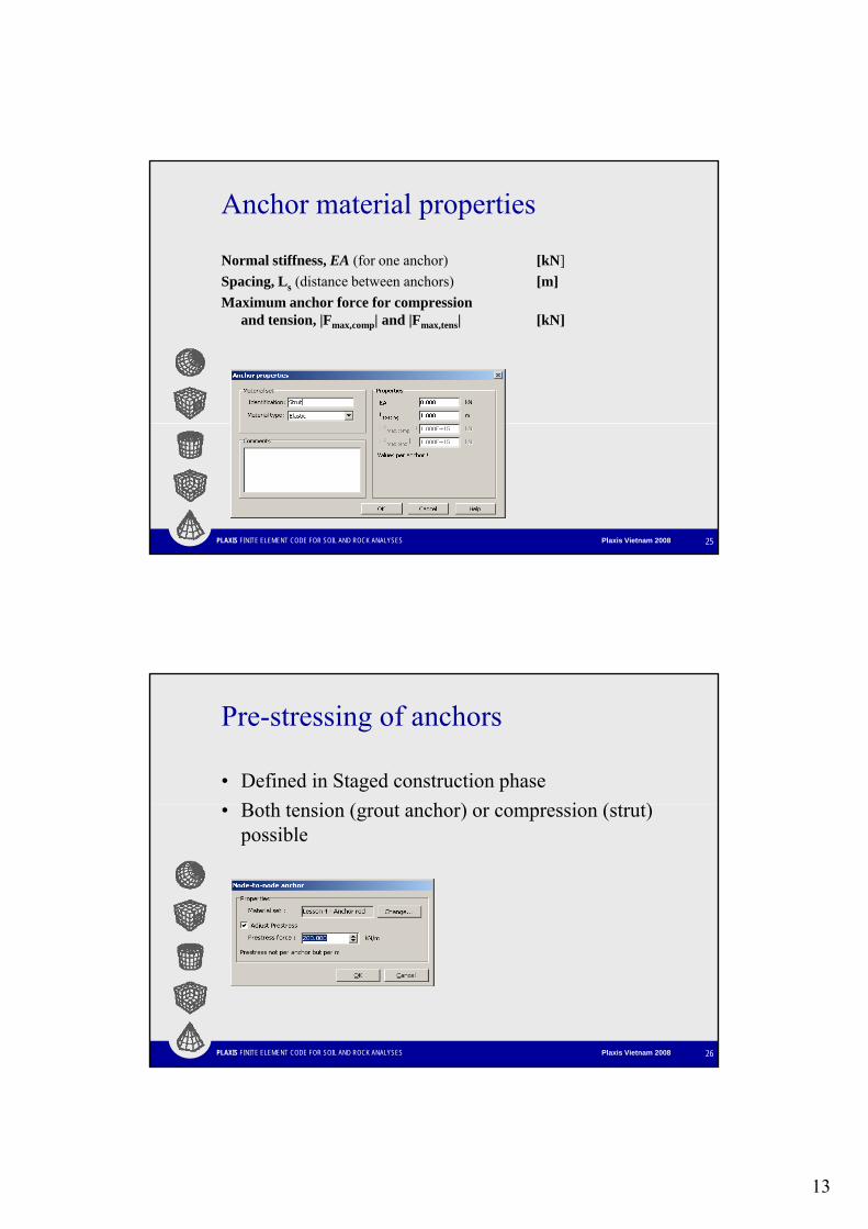
Anchor material properties
Normal stiffness, EA (for one anchor) [kN]Spacing, Ls (distance between anchors) [m]Maximum anchor force for compression
and tension, |Fmax,comp| and |Fmax,tens| [kN]
PLAXIS FINITE ELEMENT CODE FOR SOIL AND ROCK ANALYSES Plaxis Vietnam 2008 16
9
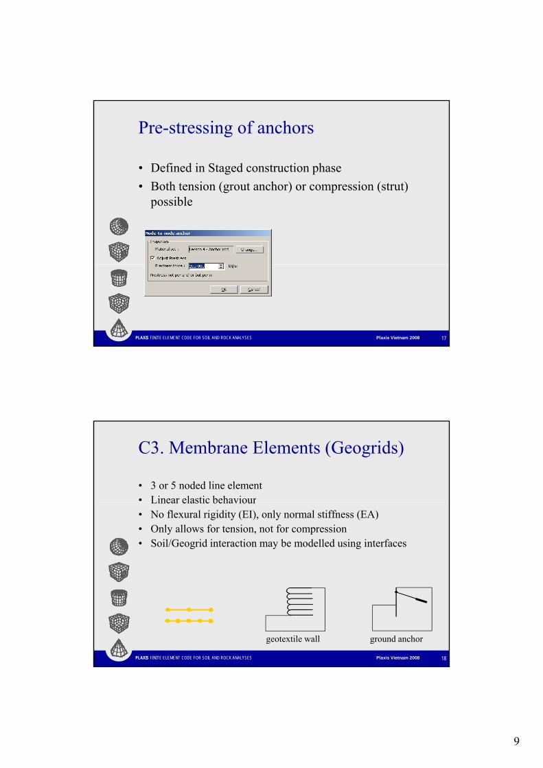
Pre-stressing of anchors
• Defined in Staged construction phaseB h i ( h ) i ( )• Both tension (grout anchor) or compression (strut) possible
PLAXIS FINITE ELEMENT CODE FOR SOIL AND ROCK ANALYSES Plaxis Vietnam 2008 17
C3. Membrane Elements (Geogrids)
• 3 or 5 noded line element• Linear elastic behaviourLinear elastic behaviour• No flexural rigidity (EI), only normal stiffness (EA)• Only allows for tension, not for compression• Soil/Geogrid interaction may be modelled using interfaces
PLAXIS FINITE ELEMENT CODE FOR SOIL AND ROCK ANALYSES Plaxis Vietnam 2008 18
geotextile wall ground anchor
10
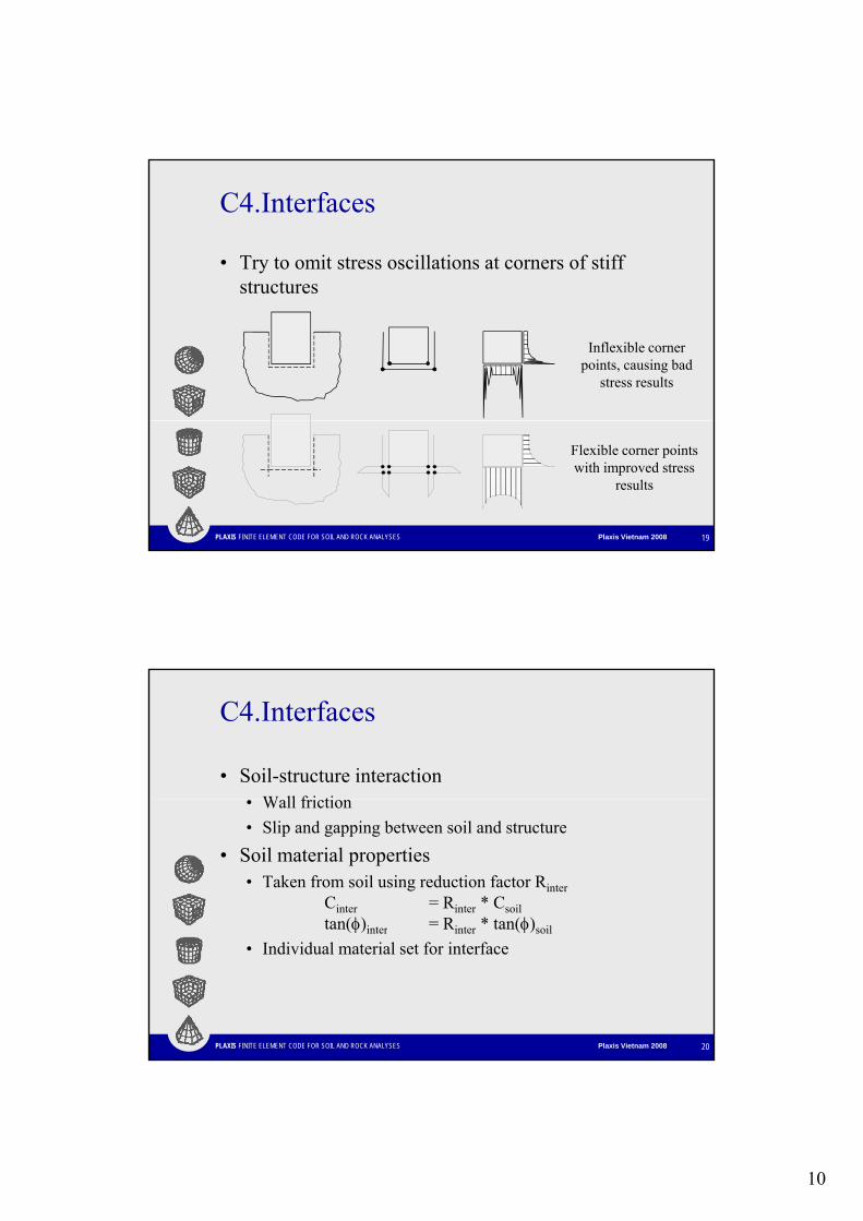
C4.Interfaces
• Try to omit stress oscillations at corners of stiff structuresstructures
Inflexible corner points, causing bad
stress results
PLAXIS FINITE ELEMENT CODE FOR SOIL AND ROCK ANALYSES Plaxis Vietnam 2008 19
Flexible corner points with improved stress
results
C4.Interfaces
• Soil-structure interactionW ll f i ti• Wall friction
• Slip and gapping between soil and structure• Soil material properties
• Taken from soil using reduction factor RinterCinter = Rinter * Csoiltan(φ)inter = Rinter * tan(φ)soil
PLAXIS FINITE ELEMENT CODE FOR SOIL AND ROCK ANALYSES Plaxis Vietnam 2008 20
(φ)inter inter (φ)soil
• Individual material set for interface
11
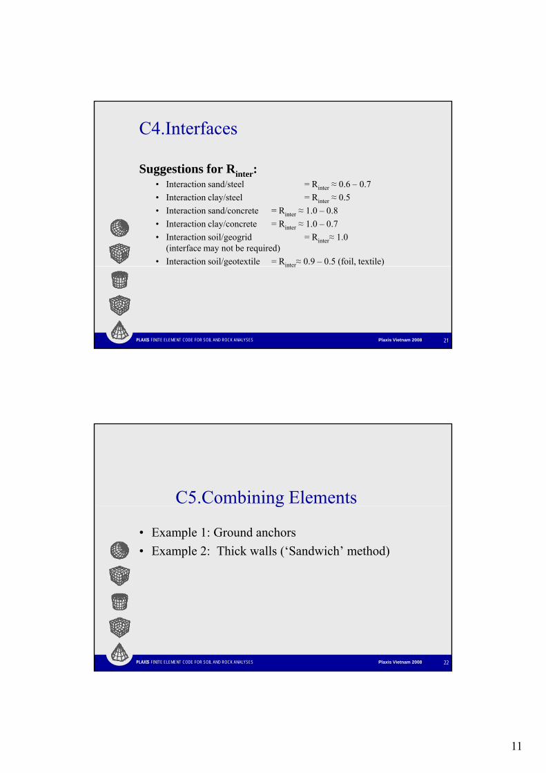
C4.Interfaces
Suggestions for Rinter:• Interaction sand/steel = R ≈ 0 6 0 7• Interaction sand/steel = Rinter ≈ 0.6 – 0.7• Interaction clay/steel = Rinter ≈ 0.5• Interaction sand/concrete = Rinter ≈ 1.0 – 0.8• Interaction clay/concrete = Rinter ≈ 1.0 – 0.7• Interaction soil/geogrid = Rinter≈ 1.0
(interface may not be required)• Interaction soil/geotextile = Rinter≈ 0.9 – 0.5 (foil, textile)
PLAXIS FINITE ELEMENT CODE FOR SOIL AND ROCK ANALYSES Plaxis Vietnam 2008 21
inter
C5.Combining Elementsg
• Example 1: Ground anchors• Example 2: Thick walls (‘Sandwich’ method)
PLAXIS FINITE ELEMENT CODE FOR SOIL AND ROCK ANALYSES Plaxis Vietnam 2008 22
12
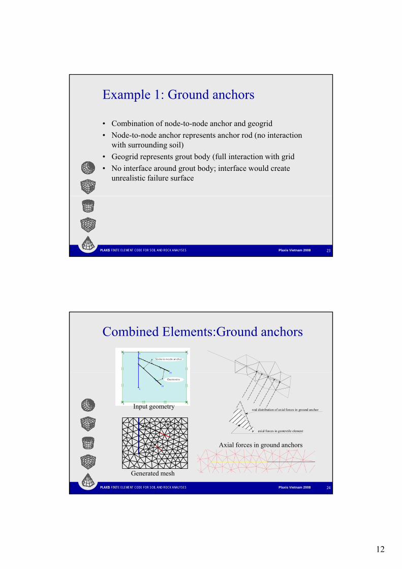
Example 1: Ground anchors
• Combination of node-to-node anchor and geogrid• Node to node anchor represents anchor rod (no interaction• Node-to-node anchor represents anchor rod (no interaction
with surrounding soil)• Geogrid represents grout body (full interaction with grid• No interface around grout body; interface would create
unrealistic failure surface
PLAXIS FINITE ELEMENT CODE FOR SOIL AND ROCK ANALYSES Plaxis Vietnam 2008 23
Combined Elements:Ground anchors
axial forces in geotextile element
real distribution of axial forces in ground anchorInput geometry
PLAXIS FINITE ELEMENT CODE FOR SOIL AND ROCK ANALYSES Plaxis Vietnam 2008 24
Generated mesh
Axial forces in ground anchors
13
Anchor material properties
Normal stiffness, EA (for one anchor) [kN]Spacing, Ls (distance between anchors) [m]Maximum anchor force for compression
and tension, |Fmax,comp| and |Fmax,tens| [kN]
PLAXIS FINITE ELEMENT CODE FOR SOIL AND ROCK ANALYSES Plaxis Vietnam 2008 25
Pre-stressing of anchors
• Defined in Staged construction phaseB h i ( h ) i ( )• Both tension (grout anchor) or compression (strut) possible
PLAXIS FINITE ELEMENT CODE FOR SOIL AND ROCK ANALYSES Plaxis Vietnam 2008 26
14
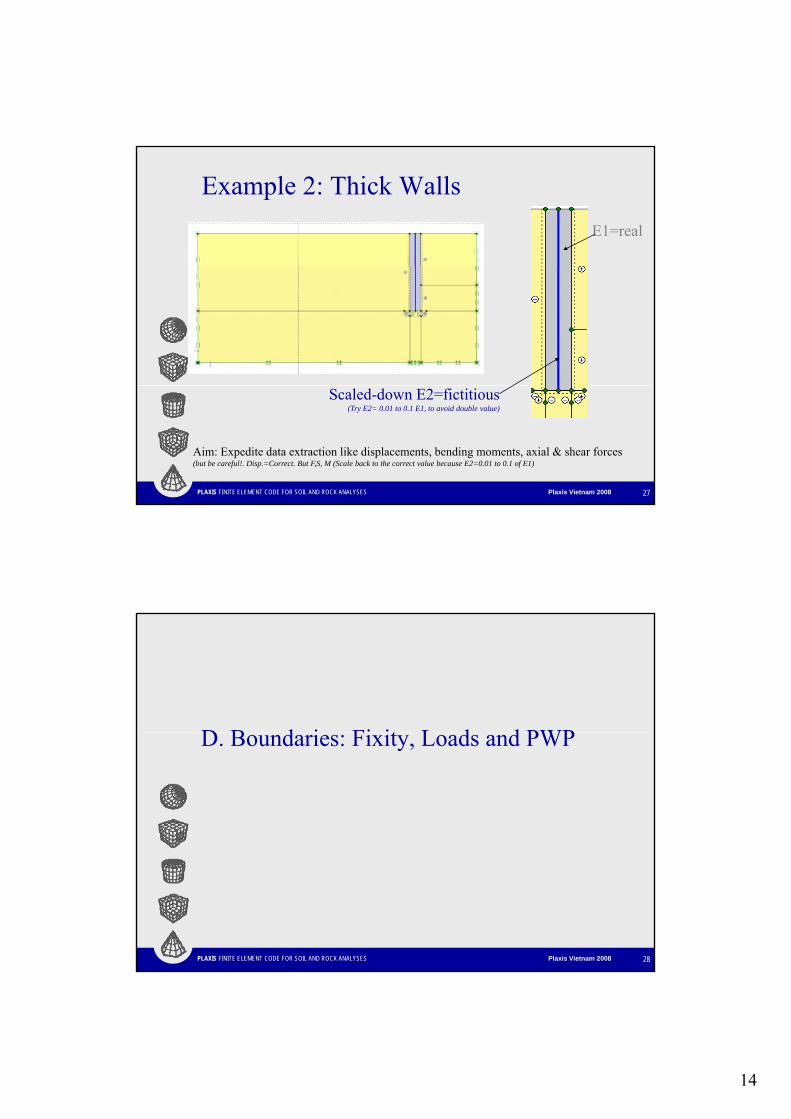
Example 2: Thick WallsE1=real
PLAXIS FINITE ELEMENT CODE FOR SOIL AND ROCK ANALYSES Plaxis Vietnam 2008 27
Scaled-down E2=fictitious(Try E2= 0.01 to 0.1 E1, to avoid double value)
Aim: Expedite data extraction like displacements, bending moments, axial & shear forces(but be careful!. Disp.=Correct. But F,S, M (Scale back to the correct value because E2=0.01 to 0.1 of E1)
D B d i Fi it L d d PWPD. Boundaries: Fixity, Loads and PWP
PLAXIS FINITE ELEMENT CODE FOR SOIL AND ROCK ANALYSES Plaxis Vietnam 2008 28
15
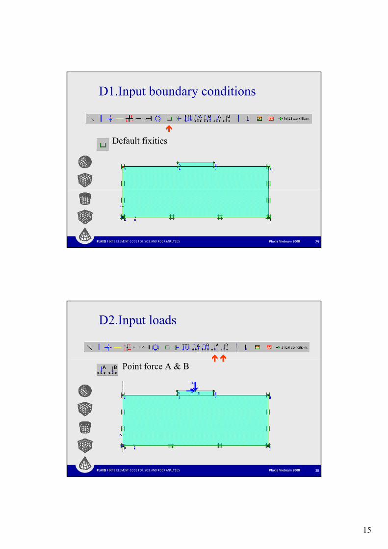
D1.Input boundary conditions
Default fixities
PLAXIS FINITE ELEMENT CODE FOR SOIL AND ROCK ANALYSES Plaxis Vietnam 2008 29
D2.Input loads
Point force A & B
PLAXIS FINITE ELEMENT CODE FOR SOIL AND ROCK ANALYSES Plaxis Vietnam 2008 30
16
D3.Porewater Generation
• Wet excavationI bl ( t ) ti fl• Impermeable (concrete) excavation floor
• Dry excavation• Undisturbed water table outside excavation• Drawdown outside excavation
PLAXIS FINITE ELEMENT CODE FOR SOIL AND ROCK ANALYSES Plaxis Vietnam 2008 31
D4.Options
• General phreatic levelApplies to all clusters that have not been separately defined.
L li d / Cl h i l l
A. Steady-state condition (Default)
• Localised / Cluster phreatic levelApplies to one specific cluster.
• Localised / Cluster dryMakes a specific cluster dry.
• InterpolateInterpolate pore pressures between clusters above and below.
• User-defined pore pressureS if t l l d i t i di ti
PLAXIS FINITE ELEMENT CODE FOR SOIL AND ROCK ANALYSES Plaxis Vietnam 2008 32
Specify pressure pref at level yref and increase pinc per meter in y-direction.
B. Transient-state condition (Plaxis + Plaxflow Integration)• Same input procedure
17
D5.Wet excavation
• Excavate without changing water conditions (in stages or at once)stages or at once)
• Pore pressures outside excavated area remain unchanged
PLAXIS FINITE ELEMENT CODE FOR SOIL AND ROCK ANALYSES Plaxis Vietnam 2008 33
D6.Dry excavationUndisturbed water table outside excavation• For every excavation phase do
• Excavate soil• Set excavated area dry• Define area just below excavation floor as interpolate between
lines or clusters
Suitable for short-term excavations in lowbili il
PLAXIS FINITE ELEMENT CODE FOR SOIL AND ROCK ANALYSES Plaxis Vietnam 2008 34
permeability soils
18
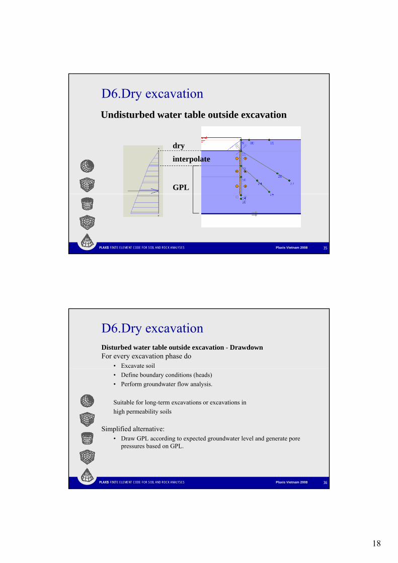
D6.Dry excavationUndisturbed water table outside excavation
dry
interpolate
GPL
PLAXIS FINITE ELEMENT CODE FOR SOIL AND ROCK ANALYSES Plaxis Vietnam 2008 35
D6.Dry excavationDisturbed water table outside excavation - DrawdownFor every excavation phase do
• Excavate soil• Define boundary conditions (heads)• Perform groundwater flow analysis.
Suitable for long-term excavations or excavations inhigh permeability soils
Simplified alternative:
PLAXIS FINITE ELEMENT CODE FOR SOIL AND ROCK ANALYSES Plaxis Vietnam 2008 36
Simplified alternative:• Draw GPL according to expected groundwater level and generate pore
pressures based on GPL.
19
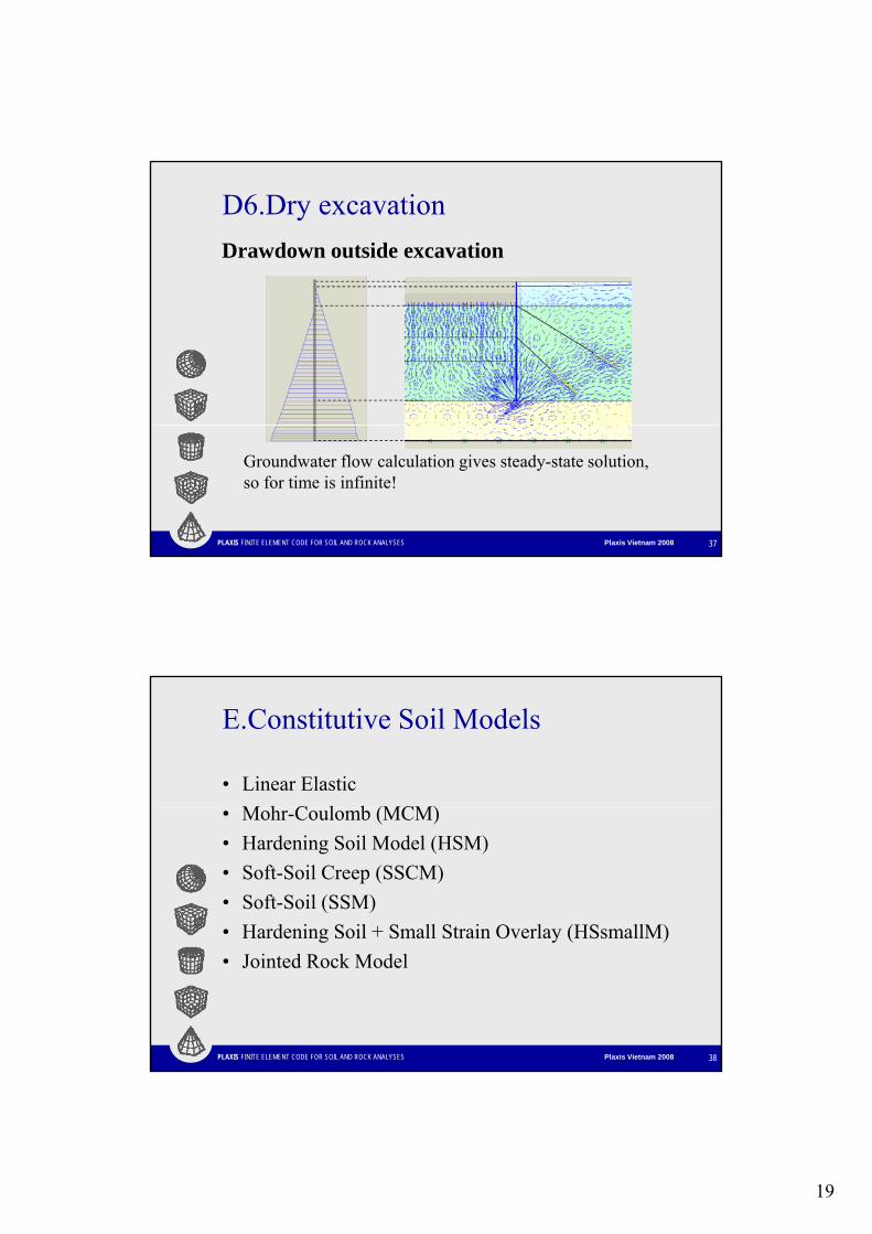
D6.Dry excavationDrawdown outside excavation
PLAXIS FINITE ELEMENT CODE FOR SOIL AND ROCK ANALYSES Plaxis Vietnam 2008 37
Groundwater flow calculation gives steady-state solution,so for time is infinite!
E.Constitutive Soil Models
• Linear ElasticM h C l b (MCM)• Mohr-Coulomb (MCM)
• Hardening Soil Model (HSM)• Soft-Soil Creep (SSCM)• Soft-Soil (SSM)• Hardening Soil + Small Strain Overlay (HSsmallM)
PLAXIS FINITE ELEMENT CODE FOR SOIL AND ROCK ANALYSES Plaxis Vietnam 2008 38
g y ( )• Jointed Rock Model
20
Excavation Modelling: Workflowg
PLAXIS FINITE ELEMENT CODE FOR SOIL AND ROCK ANALYSES Plaxis Vietnam 2008 39
Model: PointsPoints
• Start and end of lines. • Positioning of anchors• Point forces• Point forces, • Point fixities
• Local refinements of the finite element mesh.
Model: LinesLines
fi h h i l b d i f h
PLAXIS FINITE ELEMENT CODE FOR SOIL AND ROCK ANALYSES Plaxis Vietnam 2008 40
• Define the physical boundaries of the geometry• Define discontinuities in the geometry:
• Sheet pile walls, distributed loads• Separations of distinct soil layers or construction stages.
• A line can have several functions or properties
21
General modelling aspects
ClustersA t ti ll t d l d• Automatically generated enclosed areas
• Homogeneous soil properties.
PLAXIS FINITE ELEMENT CODE FOR SOIL AND ROCK ANALYSES Plaxis Vietnam 2008 41
Input
C i d l• Composing a geometry model• Creating and assigning data sets• Generating a finite element mesh• Generating initial conditions
PLAXIS FINITE ELEMENT CODE FOR SOIL AND ROCK ANALYSES Plaxis Vietnam 2008 42
22
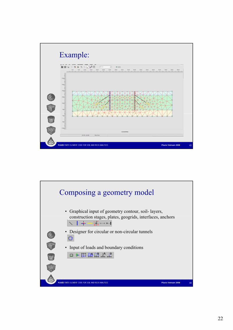
Example:
PLAXIS FINITE ELEMENT CODE FOR SOIL AND ROCK ANALYSES Plaxis Vietnam 2008 43
Composing a geometry model
• Graphical input of geometry contour, soil- layers, t ti t l t id i t f hconstruction stages, plates, geogrids, interfaces, anchors
• Designer for circular or non-circular tunnels
• Input of loads and boundary conditions
PLAXIS FINITE ELEMENT CODE FOR SOIL AND ROCK ANALYSES Plaxis Vietnam 2008 44
23
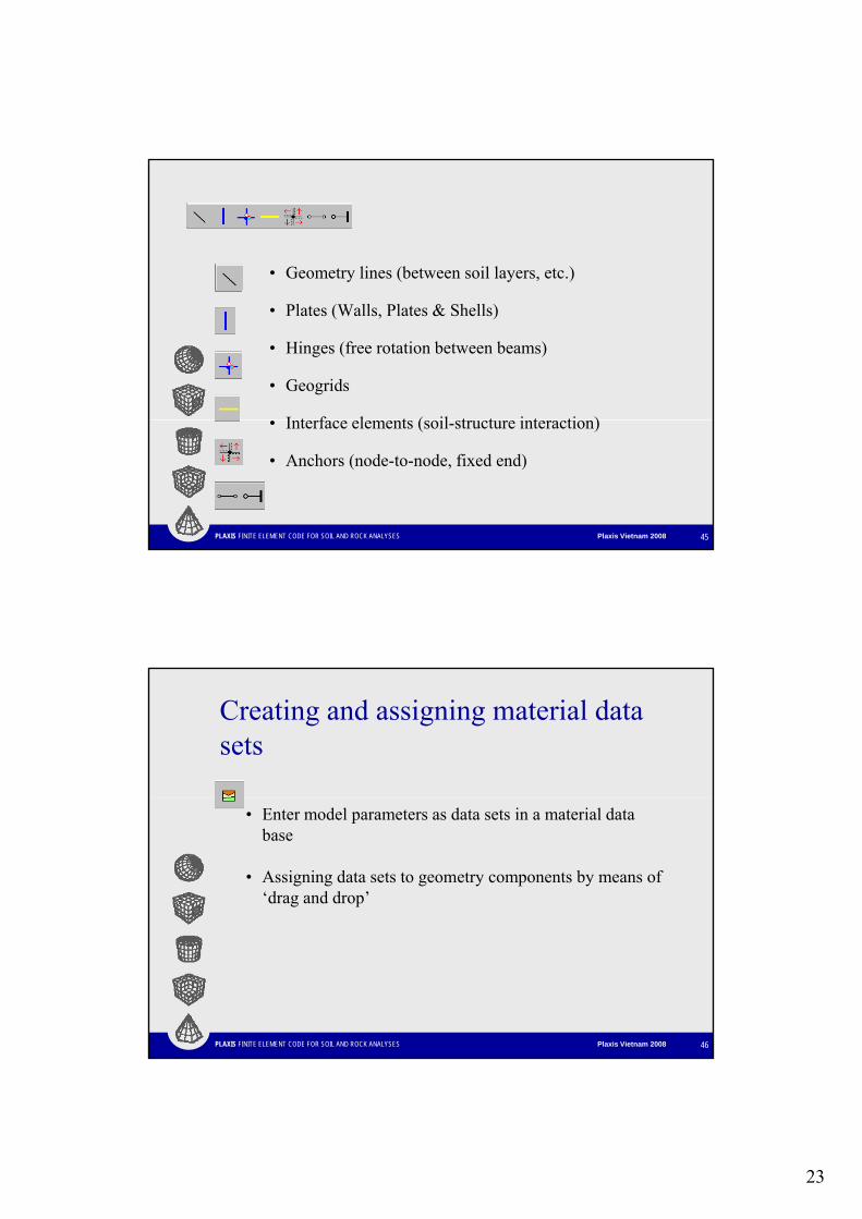
• Geometry lines (between soil layers, etc.)
• Plates (Walls, Plates & Shells)
• Hinges (free rotation between beams)
• Geogrids
I t f l t ( il t t i t ti )
PLAXIS FINITE ELEMENT CODE FOR SOIL AND ROCK ANALYSES Plaxis Vietnam 2008 45
• Interface elements (soil-structure interaction)
• Anchors (node-to-node, fixed end)
Creating and assigning material data sets
• Enter model parameters as data sets in a material data base
• Assigning data sets to geometry components by means of ‘drag and drop’
PLAXIS FINITE ELEMENT CODE FOR SOIL AND ROCK ANALYSES Plaxis Vietnam 2008 46
24
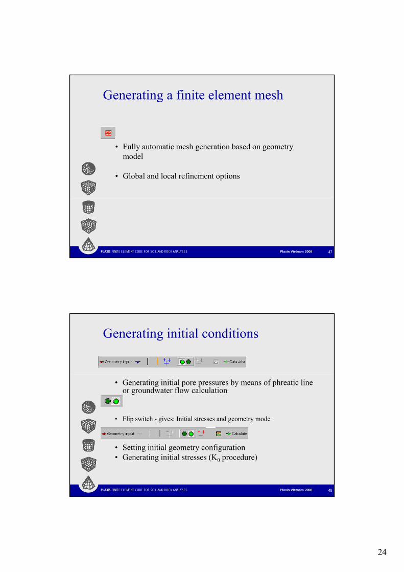
Generating a finite element mesh
• Fully automatic mesh generation based on geometry model
• Global and local refinement options
PLAXIS FINITE ELEMENT CODE FOR SOIL AND ROCK ANALYSES Plaxis Vietnam 2008 47
Generating initial conditions
• Generating initial pore pressures by means of phreatic line or groundwater flow calculation
• Flip switch - gives: Initial stresses and geometry mode
PLAXIS FINITE ELEMENT CODE FOR SOIL AND ROCK ANALYSES Plaxis Vietnam 2008 48
• Setting initial geometry configuration• Generating initial stresses (K0 procedure)
25
Defining calculation phases
• Plastic calculation, Consolidation, Phi/c reduction and Dynamic analysis.Dynamic analysis.
• Updated mesh.• Loading input: Multipliers or Staged Construction.• Changing water conditions• Multiple calculation phases can be pre-defined and executed
at once.
PLAXIS FINITE ELEMENT CODE FOR SOIL AND ROCK ANALYSES Plaxis Vietnam 2008 49
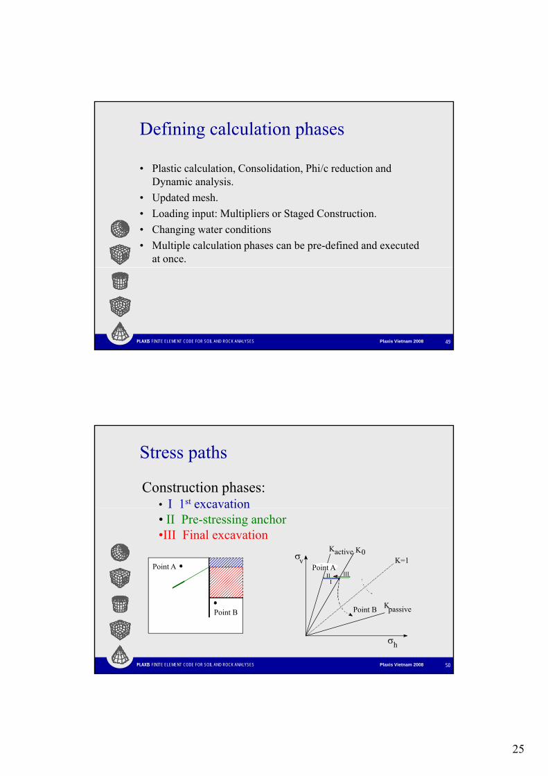
Stress paths
Construction phases:• I 1st excavation
σK
K=1v0Kactive
III III
Point APoint A
I 1 excavation• II Pre-stressing anchor•III Final excavation
PLAXIS FINITE ELEMENT CODE FOR SOIL AND ROCK ANALYSES Plaxis Vietnam 2008 50
passivePoint B K
σh
Point B
26
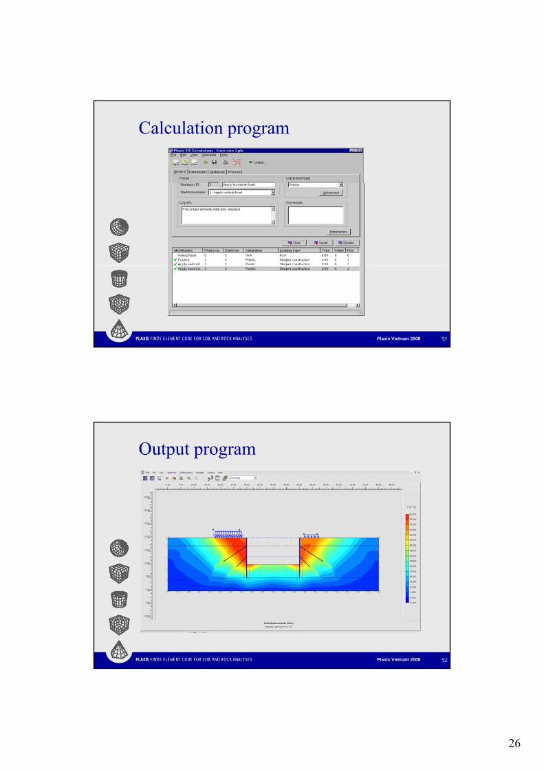
Calculation program
PLAXIS FINITE ELEMENT CODE FOR SOIL AND ROCK ANALYSES Plaxis Vietnam 2008 51
Output program
PLAXIS FINITE ELEMENT CODE FOR SOIL AND ROCK ANALYSES Plaxis Vietnam 2008 52
27
View results
• Graphical and tabulated output of displacements, stresses and structural forcesstresses and structural forces
• Output in cross sections• Multiple output windows can be opened
simultaneously (comparison of results)
PLAXIS FINITE ELEMENT CODE FOR SOIL AND ROCK ANALYSES Plaxis Vietnam 2008 53
Demonstration : Anchored Sheet-pile Wall
• See demonstration
PLAXIS FINITE ELEMENT CODE FOR SOIL AND ROCK ANALYSES Plaxis Vietnam 2008 54
28
Thank You!
PLAXIS FINITE ELEMENT CODE FOR SOIL AND ROCK ANALYSES Plaxis Vietnam 2008 55