Decadal Survey Mission Planning Presentation to CLARREO Workshop Steve Volz October 21, 2008.
Upload
trinhtuyenCategory
view
239download
0
Modeling polarized radiation for CLARREO inter-calibration applications
Wenbo Sun, Bruce Wielicki, Constantine Lukashin, and David Young
• Introduction
• Polarization fundamentals
• Correction of measurement errors caused by polarization
• The polarized radiative transfer model
• Modeling polarized radiation for clear ocean
• Modeling polarized radiation for clouds
• Summary

Introduction
1. Radiation climatology requires highly accurate radiation data.
2. Instruments whose sensors are not totally depolarized may have
significant errors in measured radiance due to the polarized
incident radiation.
3. Accurate inter-calibration of CLARREO and other instruments
requires the measurement errors due to polarization to be
corrected in advance.
4. Satellite measurements of the polarization of radiation are limited
by incidence and viewing geometries and working wavelengths.
5. To make high-spectral lookup tables of polarization dependence
model (PDM), modeling of the polarization of radiation is needed.
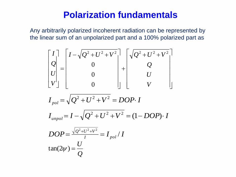
Any arbitrarily polarized incoherent radiation can be represented by
the linear sum of an unpolarized part and a 100% polarized part as
V
U
Q
VUQVUQI
V
U
Q
I 222222
0
0
0
IDOPVUQI pol 222
IDOPVUQIIunpol )1(222
IIDOP polI
VUQ/
222
Q
U)2tan(
Polarization fundamentals

Angle of linear polarization (ALP) physically is
the angle between direction and the linearly
polarized electric field vector. Zero-ALP is
always along the local meridian line. 90-degree-
ALP is ensured at a direction horizontal to the
reflecting surface on the principal plane.
Sensor
e
//e
e
*
////
* EEEEQ
*
////
* EEEEI
*
//
*
// EEEEU
E
Local meridian line
E
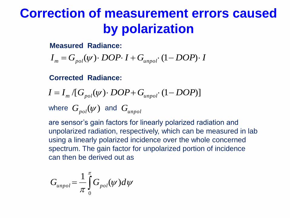
IDOPGIDOPGI unpolpolm )1()(
)]1()(/[ DOPGDOPGII unpolpolm
Measured Radiance:
Corrected Radiance:
where )(polG unpolGand
are sensor’s gain factors for linearly polarized radiation and
unpolarized radiation, respectively, which can be measured in lab
using a linearly polarized incidence over the whole concerned
spectrum. The gain factor for unpolarized portion of incidence
can then be derived out as
0
)(1
dGG polunpol
Correction of measurement errors caused
by polarization
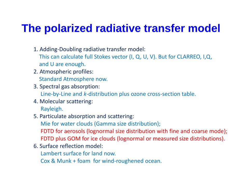
1. Adding-Doubling radiative transfer model:This can calculate full Stokes vector (I, Q, U, V). But for CLARREO, I,Q, and U are enough.
2. Atmospheric profiles: Standard Atmosphere now.
3. Spectral gas absorption: Line-by-Line and k-distribution plus ozone cross-section table.
4. Molecular scattering: Rayleigh.
5. Particulate absorption and scattering: Mie for water clouds (Gamma size distribution); FDTD for aerosols (lognormal size distribution with fine and coarse mode);FDTD plus GOM for ice clouds (lognormal or measured size distributions).
6. Surface reflection model: Lambert surface for land now.Cox & Munk + foam for wind-roughened ocean.
The polarized radiative transfer model

0 10 20 30 40 50 60 70 80 90
0.0
0.1
0.2
0.3
0.4
0.5
0.6
0.7
RAZ = 180o
VZA (o)
Re
fle
cta
nce
90 80 70 60 50 40 30 20 10 0
0.0
0.1
0.2
0.3
0.4
0.5
0.6
0.7
Ocean Wind:
2.5 m/s
5.0 m/s
7.5 m/s
10.0 m/s
15.0 m/s
VZA (o)
WL = 670 nm
SZA = 30o
RAZ = 0o
Re
fle
cta
nce
90 80 70 60 50 40 30 20 10 0
0.0
0.1
0.2
0.3
0.4
0.5
0.6
0.7
0.8
0.9
1.0
Ocean Wind:
2.5 m/s
5.0 m/s
7.5 m/s
10.0 m/s
15.0 m/s
WL = 670 nm
SZA = 30o
RAZ = 0o
DO
P
VZA (o)
0 10 20 30 40 50 60 70 80 90
0.0
0.1
0.2
0.3
0.4
0.5
0.6
0.7
0.8
0.9
1.0
RAZ = 180o
DO
P
VZA (o)
Sea-Salt AOT = 0.075
Sensitivity of clear ocean total reflectance and DOP to wind speed

10 20 30 40 50 60
5
10
15
20
25
30
35
Wind = 12.5 m/s
DO
P
RAZ ( x 3o )
VZ
A (
1.9
o...8
8.7
o in
Ga
ussia
n Q
ua
dra
ture
)
0.0
0.1
0.2
0.3
0.4
0.5
0.6
0.7
0.8
0.9
1.010 20 30 40 50 60
5
10
15
20
25
30
35
Wind = 7.5 m/s
DO
P
RAZ ( x 3o )
VZ
A (
1.9
o...8
8.7
o in
Ga
ussia
n Q
ua
dra
ture
)
0.0
0.1
0.2
0.3
0.4
0.5
0.6
0.7
0.8
0.9
1.010 20 30 40 50 60
5
10
15
20
25
30
35
WL = 670 nm
SZA = 30o
RAZ = 0o
Wind = 2.5 m/s
DO
PRAZ ( x 3
o )
VZ
A (
1.9
o...8
8.7
o in
Ga
ussia
n Q
ua
dra
ture
)
0.0
0.1
0.2
0.3
0.4
0.5
0.6
0.7
0.8
0.9
1.0
10 20 30 40 50 60
5
10
15
20
25
30
35
Wind = 2.5 m/s
WL = 670 nm
SZA = 30o
RAZ = 0o
AL
P
RAZ ( x 3o )
VZ
A (
1.9
o...8
8.7
o in
Ga
ussia
n Q
ua
dra
ture
)
0
15
30
45
60
75
90
105
120
135
150
165
18010 20 30 40 50 60
5
10
15
20
25
30
35
AL
P
Wind = 7.5 m/s
RAZ ( x 3o )
VZ
A (
1.9
o...8
8.7
o in
Ga
ussia
n Q
ua
dra
ture
)
0
15
30
45
60
75
90
105
120
135
150
165
18010 20 30 40 50 60
5
10
15
20
25
30
35
Wind = 12.5 m/s
AL
P
RAZ ( x 3o )
VZ
A (
1.9
o...8
8.7
o in
Ga
ussia
n Q
ua
dra
ture
)
0
15
30
45
60
75
90
105
120
135
150
165
180
(Sea-salt AOT = 0.075)
Wind = 2.5 m/s Wind = 7.5 m/s Wind = 12.5 m/s
Sensitivity of clear ocean DOP and ALP to wind
speed

90 80 70 60 50 40 30 20 10 0
0.0
0.1
0.2
0.3
0.4
0.5
0.6
0.7
0.8
0.9
1.0
AOT = 0.00
AOT = 0.075
AOT = 0.075 x 2
WL = 670 nm
SZA = 30o
RAZ = 0o
Wind = 7.5 m/s
DO
P
VZA (o)
0 10 20 30 40 50 60 70 80 90
0.0
0.1
0.2
0.3
0.4
0.5
0.6
0.7
0.8
0.9
1.0
RAZ = 180o
DO
P
VZA (o)
Sensitivity of clear ocean DOP and ALP to aerosol
90 80 70 60 50 40 30 20 10 0
0.00
0.05
0.10
0.15
0.20
0.25
0.30
0.35
AOT = 0.00
AOT = 0.075
AOT = 0.075 x 2
WL = 670 nm
SZA = 30o
RAZ = 0o
Wind = 7.5 m/s
VZA ( o )
Re
fle
cta
nce
0 10 20 30 40 50 60 70 80 90
0.00
0.05
0.10
0.15
0.20
0.25
0.30
0.35
Re
fle
cta
nce
RAZ = 180o
VZA ( o )

90 80 70 60 50 40 30 20 10 0
0.0
0.1
0.2
0.3
0.4
0.5
0.6
0.7
0.8
0.9
1.0
SZA = 60o
SZA = 30o
WL = 670 nm
Wind = 7.5 m/s
RAZ = 0o
VZA ( o )
DO
P
0 10 20 30 40 50 60 70 80 90
0.0
0.1
0.2
0.3
0.4
0.5
0.6
0.7
0.8
0.9
1.0
RAZ = 180o
DO
P
VZA ( o )
Sensitivity of clear ocean total reflectance and DOP to solar zenith angle
90 80 70 60 50 40 30 20 10 0
0.0
0.5
1.0
1.5
2.0
2.5
3.0
SZA = 60o
SZA = 30o
WL = 670 nm
Wind = 7.5 m/s
RAZ = 0o
Re
fle
cta
nce
VZA (o)
0 10 20 30 40 50 60 70 80 90
0.0
0.5
1.0
1.5
2.0
2.5
3.0
RAZ = 180o
VZA (o)
Re
fle
cta
nce

DO
P
SZA = 60o
WL = 670 nm
Wind = 7.5 m/s
AOT = 0.075
X Axis Title
Y A
xis
Title
0.0
0.1
0.2
0.3
0.4
0.5
0.6
0.7
0.8
0.9
1.0
Sensitivity of clear ocean DOP to solar
zenith angle
SZA = 30o
WL = 670 nm
Wind = 7.5 m/s
AOT = 0.075
DO
P
X Axis Title
Y A
xis
Title
0.0
0.1
0.2
0.3
0.4
0.5
0.6
0.7
0.8
0.9
1.0
Radiance in the blue
angle range has ~0
degree of polarization.
These neutral-
polarization VZAs are
suitable for calibrating
polarized sensors such
as the instruments on
PARASOL or Glory.
0 10 20 30 40 50 60 70 80 90
0.0
0.1
0.2
0.3
0.4
0.5
0.6
0.7
0.8
0.9
1.0
RAZ = 180o
DO
P
VZA (o)
90 80 70 60 50 40 30 20 10 0
0.0
0.1
0.2
0.3
0.4
0.5
0.6
0.7
0.8
0.9
1.0
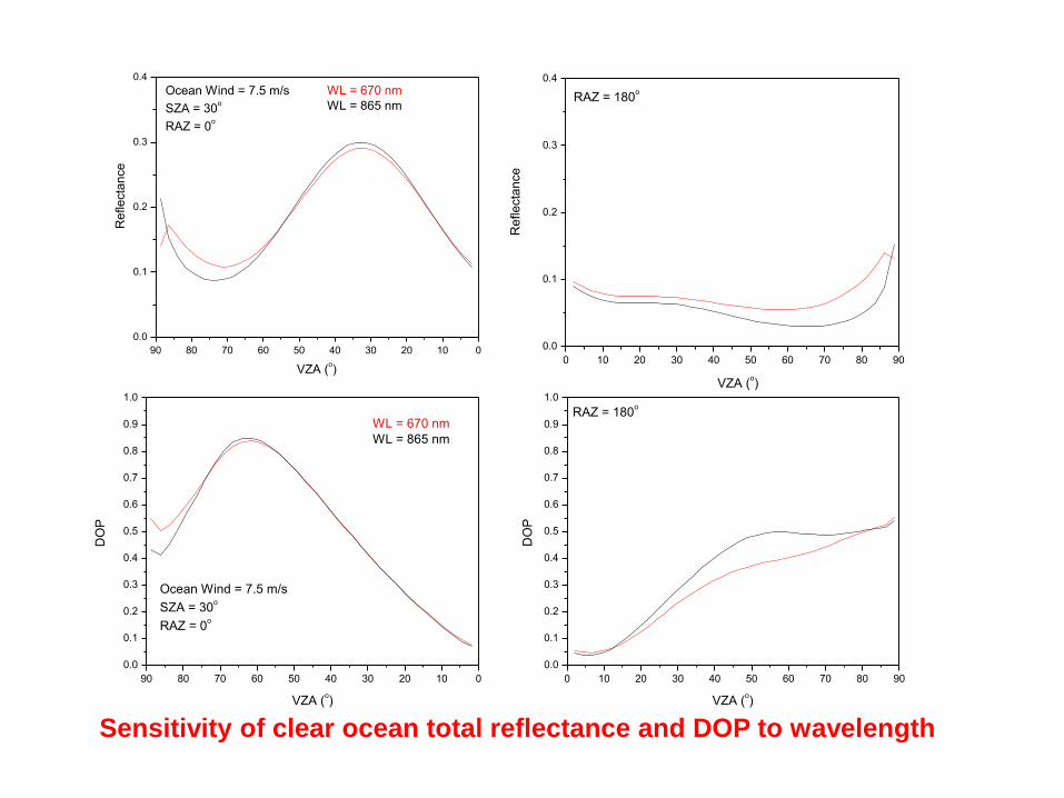
WL = 670 nm
WL = 865 nm
Ocean Wind = 7.5 m/s
SZA = 30o
RAZ = 0o
DO
P
VZA (o)
Sensitivity of clear ocean total reflectance and DOP to wavelength
0 10 20 30 40 50 60 70 80 90
0.0
0.1
0.2
0.3
0.4
RAZ = 180o
VZA (o)
Re
fle
cta
nce
90 80 70 60 50 40 30 20 10 0
0.0
0.1
0.2
0.3
0.4
Ocean Wind = 7.5 m/s
SZA = 30o
RAZ = 0o
VZA (o)
WL = 670 nm
WL = 865 nm
Re
fle
cta
nce

0 10 20 30 40 50 60 70 80 90
0.0
0.1
0.2
0.3
0.4
0.5
0.6
0.7
0.8
0.9
1.0
RAZ = 180o
DO
P
VZA (o)
90 80 70 60 50 40 30 20 10 0
0.0
0.1
0.2
0.3
0.4
0.5
0.6
0.7
0.8
0.9
1.0
WL = 670 nm
SZA = 30o
RAZ = 0o
Wind = 7.5 m/s
AOT = 0.075
DO
P
VZA (o)
MLS gas absorption
MLS gas absorption x 20
Atmospheric gas absorption does NOT affect DOP
90 80 70 60 50 40 30 20 10 0
0.0
0.1
0.2
0.3
0.4
VZA (o)
MLS gas absorption
MLS gas absorption x 20
WL = 670 nm
SZA = 30o
RAZ = 0o
Wind = 7.5 m/s
AOT = 0.075
Re
fle
cta
nce
0 10 20 30 40 50 60 70 80 90
0.0
0.1
0.2
0.3
0.4
VZA (o)
RAZ = 180o
Re
fle
cta
nce

0 10 20 30 40 50 60 70 80 90 100110120130140150160170180
0.01
0.1
1
10
100
1000
10000
f is the fraction of the scattered
energy adjusted off
Slope of truncation line is determined
by the 2 neighboring points near the
Delta angle limit
P1
1
Scattering Angle (deg)
Delta-adjustment to cloud phase functions is done to avoid too many Legendre terms and streams in the RT calculation.
Other elements of phase matrix are adjusted with conserving their ratio values to the phase function.
0 30 60 90 120 150 180
-1.0
-0.8
-0.6
-0.4
-0.2
0.0
0.2
0.4
0.6
0.8
1.0
Scattering Angle (deg)
-P1
2 / P
11
0 30 60 90 120 150 180
0.0
0.2
0.4
0.6
0.8
1.0
1.2
1.4
1.6
1.8
2.0
Scattering Angle (deg)
P2
2 / P
11
0 30 60 90 120 150 180
-1.0
-0.8
-0.6
-0.4
-0.2
0.0
0.2
0.4
0.6
0.8
1.0
Scattering Angle (deg)
P3
3 / P
11
0 30 60 90 120 150 180
-1.0
-0.8
-0.6
-0.4
-0.2
0.0
0.2
0.4
0.6
0.8
1.0
P4
4 / P
11
Scattering Angle (deg)
0 30 60 90 120 150 180
-1.0
-0.8
-0.6
-0.4
-0.2
0.0
0.2
0.4
0.6
0.8
1.0
P3
4 / P
11
Scattering Angle (deg)
Delta-adjustment to cloud optical properties
''
sa
ss f )1('
''' / s
Modeling polarized radiation for clouds

0 10 20 30 40 50 60 70 80 90 100110120130140150160170180
0.01
0.1
1
10
100
1000
10000
f = 0.426
Delta-adjusted Phase Function
P1
1
Scattering Angle (deg)
Original Phase Function
0 10 20 30 40 50 60 70 80 90 100110120130140150160170180
0.01
0.1
1
10
100
1000
10000
f = 0.493
Delta-adjusted Normalized Phase Function
P1
1Scattering Angle (deg)
Original Phase Function
Water Cloud Ice Cloud
Delta-adjusted phase functions of water and ice clouds used in this calculation

90 80 70 60 50 40 30 20 10 0
0.2
0.3
0.4
0.5
0.6
0.7
RAZ = 0o
Re
fle
cta
nce
VZA (o)
0 10 20 30 40 50 60 70 80 90
0.0
0.1
0.2
0.3
0.4
RAZ = 180o
VZA (o)
DO
P
90 80 70 60 50 40 30 20 10 0
0.0
0.1
0.2
0.3
0.4
RAZ = 0o
WL = 670 nm
Optical Thickness = 2 x 7.07
Optical Thickness = 7.07
DO
P
VZA (o)
Water cloud
Sensitivity of TOA reflectance and DOP to water cloud optical thickness
0 10 20 30 40 50 60 70 80 90
0.2
0.3
0.4
0.5
0.6
0.7
RAZ = 180o
Re
fle
cta
nce
VZA (o)

0 30 60 90
90 60 30 0
0.4
0.5
0.6
0.7
0.8
0.9
Ice Cloud
Water Cloud
SZA = 30 deg
WL = 865 nmTo
tal R
efle
cta
nce
Loeb et al (2005)
CERES SW anisotropic factors in the principal plane
Water Clouds Ice Clouds
Model results have excellent
agreement with CERES data in
total radiance angular anisotropy,
except the ice cloud specular
reflection, since we assume pure
randomly oriented ice crystals
in the model.

Sensitivity of DOP and ALP to water cloud optical thickness
10 20 30 40 50 60
5
10
15
20
25
30
35
WL = 670 nm
SZA = 30o
Water Cloud
OD = 7.07
DO
P
RAZ ( x 3o )
VZ
A (
1.9
o...8
8.7
o in
Ga
ussia
n Q
ua
dra
ture
)
0.00
0.05
0.10
0.15
0.20
0.25
0.30
0.35
0.40
0.45
0.50 10 20 30 40 50 60
5
10
15
20
25
30
35
DO
P
WL = 670 nm
SZA = 30o
Water Cloud
OD = 2 x 7.07
VZ
A (
1.9
o...8
8.7
o in
Ga
ussia
n Q
ua
dra
ture
)
RAZ ( x 3o )
0.00
0.05
0.10
0.15
0.20
0.25
0.30
0.35
0.40
0.45
0.50
10 20 30 40 50 60
5
10
15
20
25
30
35
RAZ ( x 3o )
AL
P
VZ
A (
1.9
o...8
8.7
o in
Ga
ussia
n Q
ua
dra
ture
)
0
15
30
45
60
75
90
105
120
135
150
165
180
WL = 670 nm
SZA = 30o
Water Cloud
OD = 7.07
10 20 30 40 50 60
5
10
15
20
25
30
35
AL
P
WL = 670 nm
SZA = 30o
Water Cloud
OD = 2 x 7.07
RAZ ( x 3o )
VZ
A (
1.9
o...8
8.7
o in
Ga
ussia
n Q
ua
dra
ture
)
0
15
30
45
60
75
90
105
120
135
150
165
180

90 80 70 60 50 40 30 20 10 0
0.2
0.3
0.4
0.5
0.6
Ocean Wind = 7.5 m/s
SZA = 30o
RAZ = 0o
VZA (o)
WL = 670 nm Water cloud OD = 7.07
WL = 865 nm Water cloud OD = 7.16
Re
fle
cta
nce
0 10 20 30 40 50 60 70 80 90
0.2
0.3
0.4
0.5
0.6
RAZ = 180o
VZA (o)
Re
fle
cta
nce
90 80 70 60 50 40 30 20 10 0
0.0
0.1
0.2
0.3
0.4
WL = 670 nm Water cloud OD = 7.07
WL = 865 nm Water cloud OD = 7.16
Ocean Wind = 7.5 m/s
SZA = 30o
RAZ = 0o
DO
P
VZA (o)
0 10 20 30 40 50 60 70 80 90
0.0
0.1
0.2
0.3
0.4
RAZ = 180o
DO
P
VZA (o)
Sensitivity of water cloud total reflectance and DOP to wavelength

10 20 30 40 50 60
5
10
15
20
25
30
35
AL
P
WL = 670 nm
Wind = 7.5 m/s
SZA = 30o
Water Cloud
OD = 7.07
RAZ ( x 3o )
VZ
A (
1.9
o...8
8.7
o in
Ga
ussia
n Q
ua
dra
ture
)
0
15
30
45
60
75
90
105
120
135
150
165
18010 20 30 40 50 60
5
10
15
20
25
30
35
AL
P
WL = 865 nm
Wind = 7.5 m/s
SZA = 30o
Water Cloud
OD = 7.16
RAZ ( x 3o )
VZ
A (
1.9
o...8
8.7
o in
Ga
ussia
n Q
ua
dra
ture
)
0
15
30
45
60
75
90
105
120
135
150
165
180
Sensitivity of water cloud ALP to wavelength

Summary
1. The polarized radiative transfer model for CLARREO inter-
calibration applications is developed and runs well.
2. Sensitivity of polarization to wavelength, atmospheric gas
absorption, ocean wind speed, aerosol, cloud optical thickness,
and incidence angle are studied.
3. Further work:
(1) modeling land surface BPDF to replace the current Lambert
land surface model;
(2) studying spectral response of the polarized radiance over both
ocean and land;
(3) calculating aerosol and ice cloud single-scattering properties;
(4) defining CLARREO PDM algorithm and data structure.