Modeling in MAYA MEL 6 - École Polytechnique Fédérale ... in maya_mel... · please use the...
21
Modeling in MAYA 6 Russell Loveridge: [email protected] ETH Z | Department Architekture | Computer Aided Architectural Manufacturing | Russell Loveridge | F56.1
Transcript of Modeling in MAYA MEL 6 - École Polytechnique Fédérale ... in maya_mel... · please use the...

Modeling in MAYA 6
Russell Loveridge: [email protected] ETH Z | Department Architekture | Computer Aided Architectural Manufacturing | Russell Loveridge | F56.1
1
Modeling in MAYA This brief handout gives a short introduction to MAYA. Only the most important and basic commands are listed here. MAYA is a very robust and complicated software package. For a full overview of all of the capabilities of MAYA please visit the ALIAS/WAVEFRONT website: www.aliaswavefront.com Included in the MAYA package are on-line tutorials, for further learning please use the tutorials and other web based tutorial resources. In this introduction mouse button abbreviations are used:
LMB – Left mouse button MMB – middle mouse button RMB – Right mouse button Maya file types : .mb – default: MAYA binary
.ma – MAYA ascii (for exchange with other MAYA versions)
.mel – MAYA programming (scripting) language file
.dxf (not recommended) polygon format for AutoCAd etc.
.iges or .igs – IGES File for data exchange with Surfcam, Rhino, FromZ….etc. supports nurbs geometries.
2
Modeling in MAYA
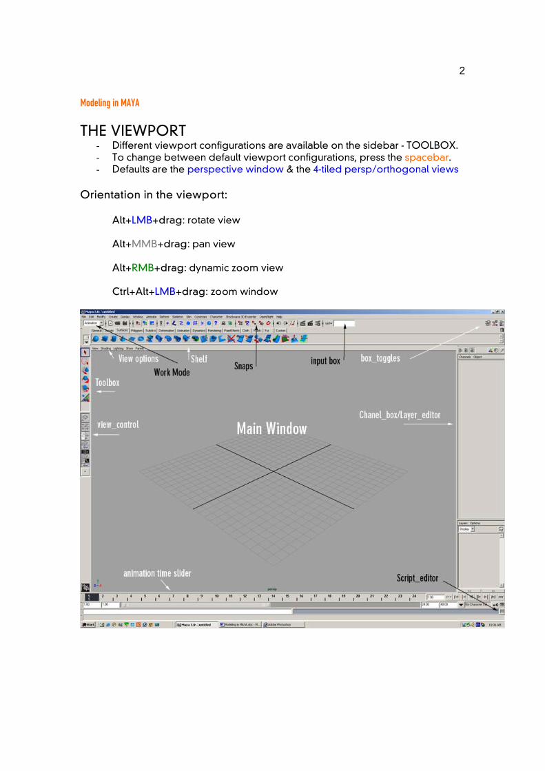
THE VIEWPORT - Different viewport configurations are available on the sidebar - TOOLBOX. - To change between default viewport configurations, press the spacebar. - Defaults are the perspective window & the 4-tiled persp/orthogonal views
Orientation in the viewport:
Alt+LMB+drag: rotate view Alt+MMB+drag: pan view Alt+RMB+drag: dynamic zoom view Ctrl+Alt+LMB+drag: zoom window
3
Modeling in MAYA Display properties:
Select object and hit “1” for rough display – (very fast graphic reaction time) “2” for medium display “3” for fine display – (slow graphic reaction time)
note: this only effects the display - not the object!!!
Select viewport and press “4” for wireframe display “5” for shaded view with default lighting “6” for shaded view, hardware texture mapping, & default lighting “7” for shaded view with scene lighting
Problems with the viewport: ? - Lost in Space: - Center view on selected object:
viewport menu>view>frame selection (SHORTCUT F) - Default view (center of grid): viewport menu>view>default home
- If the viewport navigation is behaving strange, probably the world up vector is the wrong direction.
? - Rotation and placement is incorrect : - Make sure that the z-direction is the world up axis. (Orientation of the mill) Change it with window>settings/preferences>preferences>settings
? – Want to change the view to a preset axonometric or perspective - Changing the view setup:
Spacebar – toggles between default view and last chosen view Customization of single viewports: TOOLBOX or spacebar+LMB X-ray mode: viewport menu>shading>shade options>Xray Display mapping: viewport menu>shading>enable hardware texturing
? - IF YOU LOOSE ANY OF THE TOOLBOXES OR GUI ITEMS << Display > UI Elements > “TOOLBOX” – toggles off and on. GUI = Graphical User Interface Expert Mode – NO MENU MODE! You can display ALL of the commands for MAYA by depressing and holding the space bar. If you wish to change views, depress the spacebar and click the LMB in the centre of the command field.
4
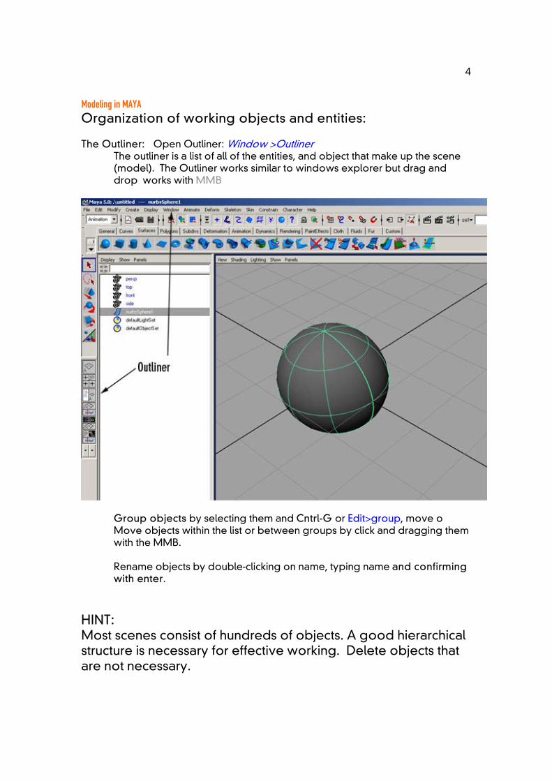
Modeling in MAYA Organization of working objects and entities: The Outliner: Open Outliner: Window >Outliner
The outliner is a list of all of the entities, and object that make up the scene (model). The Outliner works similar to windows explorer but drag and drop works with MMB
Group objects by selecting them and Cntrl-G or Edit>group, move o Move objects within the list or between groups by click and dragging them with the MMB. Rename objects by double-clicking on name, typing name and confirming with enter.
HINT: Most scenes consist of hundreds of objects. A good hierarchical structure is necessary for effective working. Delete objects that are not necessary.
5
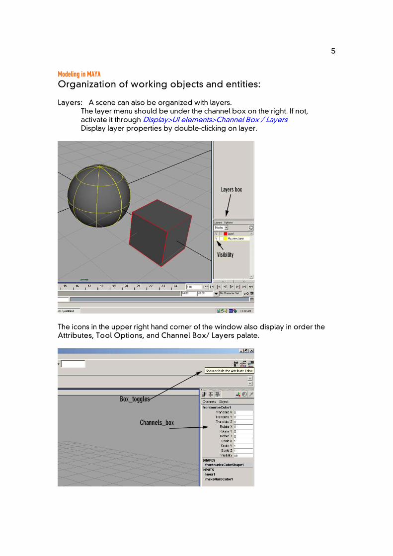
Modeling in MAYA Organization of working objects and entities: Layers: A scene can also be organized with layers.
The layer menu should be under the channel box on the right. If not, activate it through Display>UI elements>Channel Box / Layers Display layer properties by double-clicking on layer.
The icons in the upper right hand corner of the window also display in order the Attributes, Tool Options, and Channel Box/ Layers palate.
6
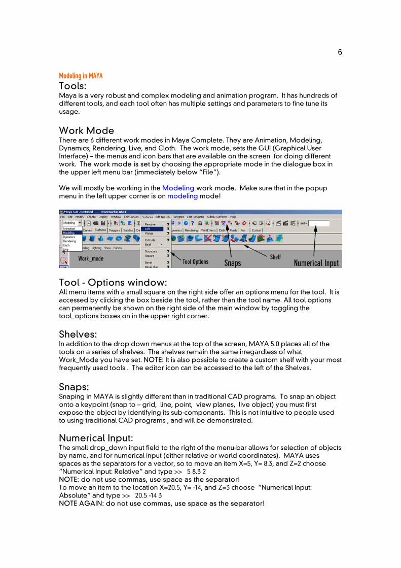
Modeling in MAYA Tools: Maya is a very robust and complex modeling and animation program. It has hundreds of different tools, and each tool often has multiple settings and parameters to fine tune its usage. Work Mode There are 6 different work modes in Maya Complete. They are Animation, Modeling, Dynamics, Rendering, Live, and Cloth. The work mode, sets the GUI (Graphical User Interface) – the menus and icon bars that are available on the screen for doing different work. The work mode is set by choosing the appropriate mode in the dialogue box in the upper left menu bar (immediately below “File”). We will mostly be working in the Modeling work mode. Make sure that in the popup menu in the left upper corner is on modeling mode!
Tool - Options window: All menu items with a small square on the right side offer an options menu for the tool. It is accessed by clicking the box beside the tool, rather than the tool name. All tool options can permanently be shown on the right side of the main window by toggling the tool_options boxes on in the upper right corner. Shelves: In addition to the drop down menus at the top of the screen, MAYA 5.0 places all of the tools on a series of shelves. The shelves remain the same irregardless of what Work_Mode you have set. NOTE: It is also possible to create a custom shelf with your most frequently used tools . The editor icon can be accessed to the left of the Shelves. Snaps: Snaping in MAYA is slightly different than in traditional CAD programs. To snap an object onto a keypoint (snap to – grid, line, point, view planes, live object) you must first expose the object by identifying its sub-componants. This is not intuitive to people used to using traditional CAD programs , and will be demonstrated.
Numerical Input: The small drop_down input field to the right of the menu-bar allows for selection of objects by name, and for numerical input (either relative or world coordinates). MAYA uses spaces as the separators for a vector, so to move an item X=5, Y= 8.3, and Z=2 choose “Numerical Input: Relative” and type >> 5 8.3 2 NOTE: do not use commas, use space as the separator! To move an item to the location X=20.5, Y= -14, and Z=3 choose “Numerical Input: Absolute” and type >> 20.5 -14 3 NOTE AGAIN: do not use commas, use space as the separator!

7
Modeling in MAYA Object transformation and manipulation tools: All objects can be manipulated at the component and sub-component level. Manual transformation of the object can be achieved by manipulating the “control handles”, by using the Transformation Tools. The transformation tools are in the toolbox on the left side. If not activate in the menu: Window>Settings/preferences>Interface>UI elements>Tool Box Manipulators -
Selection tool: used to select objects or components (SHORTCUT Q) Move tool: perpendicular to the viewport or axis wise (SHORTCUT W) Rotate tool: axis based (SHORTCUT E) Scale tool: uniform or axis wise (SHORTCUT R) Soft Modification tool: gradated sculpting tool ( no SHORTCUT)
The options for the manipulators are available by double clicking their icons in the Tool Box. All of these tool can also be found in: Modify>Transformation Tools
Selecting an object then clicking a manipulator tool, the pivot handle (x,y,z) appears. The manipulator handle appears at the center of the object (or at 0,0,0 if set to default). The manipulator has a different appearance for each of the transformation tools. The handle can be repositioned in the scene by pressing INSERT. Deactivate the “change pivot_mode” with insert key a second time.
For changing the pivot to the center of an object: Modify>center pivot
8
Modeling in MAYA Modifications with the channel box (see image pg.6) (Toggle on and off with the icon in the upper right corner) The channels box allows the user to type in numerical modifications to a selection.
- White boxes are modifiable. - Orange boxes are transformations that are locked by another command or
association - Grayed out boxes are not available for this type of object
Editors: Object can be manipulated at the unit level by using the Edit menu
Delete: Delete and Delete by type Select: Select all, Select inverse, Select by Type Duplicate: Duplicate, Duplicate with Transform Group: Create a a single group from selected objects Parent: link and manipulate multiple items based on a single item
Modifiers: The properties of an object can be modified at the attribute level by
using the Modify menu. Transformations: as seen before & also special transformation tools. Reset Transformations: resets the entity to its “zero” state. Freeze Transformations: Sets the current position as the new “zero” state. Center Pivot: Resets the Transformation pivot handle to the entity’s centre.
CONVERT: Allows you to convert one type of modeling into another type, HOWEVER!!!! It is NOT possible to convert Polygons to NURBS, only NURBS > Polygons.
Attribute Editor The attribute editor is displayed using the toggle button in the upper right corner, OR with SHORTCUT cntr-A. The attribute editor allows you to view, modify, and control all of the MANY attributes associated with each type of entity. The attricbute editor will most often be used for controlling cameras, lights, and for use in scripting different custom modifications to a particular scene.
Shortcuts – Hotkeys Any command may be given a shortcut. Many shortcuts are preset in MAYA, however to improve the efficiency of work methodology it is easy to customize new shortcuts. Window > Settings/Preferences > Hotkeys
9
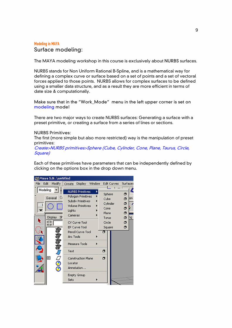
Modeling in MAYA Surface modeling: The MAYA modeling workshop in this course is exclusively about NURBS surfaces. NURBS stands for Non Uniform Rational B-Spline, and is a mathematical way for defining a complex curve or surface based on a set of points and a set of vectoral forces applied to those points. NURBS allows for complex surfaces to be defined using a smaller data structure, and as a result they are more efficient in terms of date size & computationally. Make sure that in the “Work_Mode” menu in the left upper corner is set on modeling mode! There are two major ways to create NURBS surfaces: Generating a surface with a preset primitive, or creating a surface from a series of lines or sections. NURBS Primitives: The first (more simple but also more restricted) way is the manipulation of preset primitives: Create>NURBS primitives>Sphere (Cube, Cylinder, Cone, Plane, Taurus, Circle, Square) Each of these primitives have parameters that can be independently defined by clicking on the options box in the drop down menu.
10
Modeling in MAYA NURBS lines and generating surfaces: First you must understand the issues of the DEGREE of a line. Degree of curvature:
1 (polygon – straight segments between points) 3 cubic (curved line interpolation 3 Control Points) 5 (curved line interpolation over 5 Control Points = smoother) 7 (curved line interpolation over 7 Control Points = much smoother)
The spline (or NURBS curve) degree is the average curvature between the degree number of points. A 7 degree spline will pass through the 1st, 4th and 7th point, and will be averaged over three points on either side of any given point (above a 7 point line). This is why a 7 degree spline will be “smoother” than a 5 degree spline (2 points on either side of a central point above 5 points).
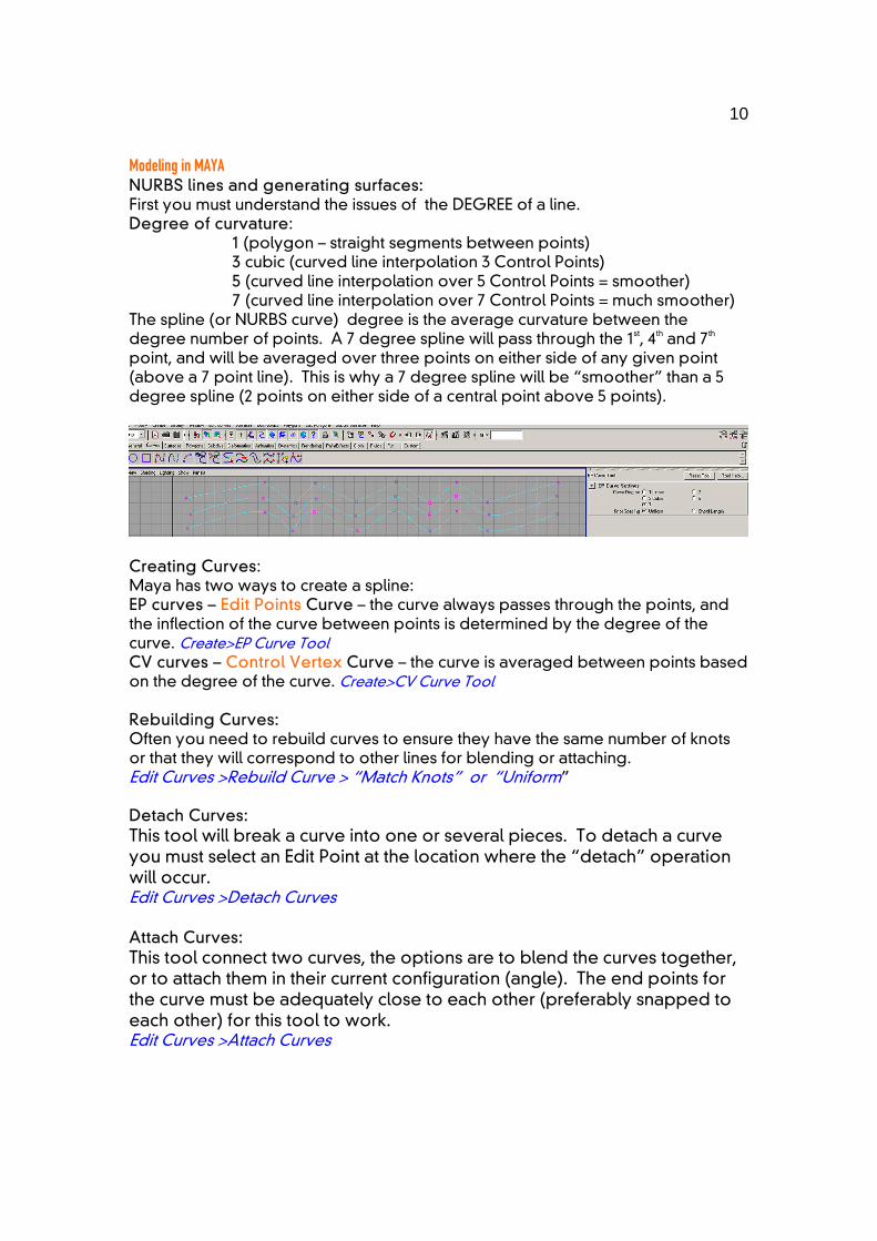
Creating Curves: Maya has two ways to create a spline: EP curves – Edit Points Curve – the curve always passes through the points, and the inflection of the curve between points is determined by the degree of the curve. Create>EP Curve Tool CV curves – Control Vertex Curve – the curve is averaged between points based on the degree of the curve. Create>CV Curve Tool Rebuilding Curves: Often you need to rebuild curves to ensure they have the same number of knots or that they will correspond to other lines for blending or attaching. Edit Curves >Rebuild Curve > “Match Knots” or “Uniform” Detach Curves: This tool will break a curve into one or several pieces. To detach a curve you must select an Edit Point at the location where the “detach” operation will occur. Edit Curves >Detach Curves Attach Curves: This tool connect two curves, the options are to blend the curves together, or to attach them in their current configuration (angle). The end points for the curve must be adequately close to each other (preferably snapped to each other) for this tool to work. Edit Curves >Attach Curves
11
Modeling in MAYA Creating a surface with lines: For creating surfaces through lines it is advantageous to have lines with the same amount of control points. The simplest way is to be always conscious about this during creating lines and afterwards use the rebuild curves command in Edit Curves. Here you can either rebuild uniform with a certain number of subdivisions or simply activate multiple curves and click match knots.
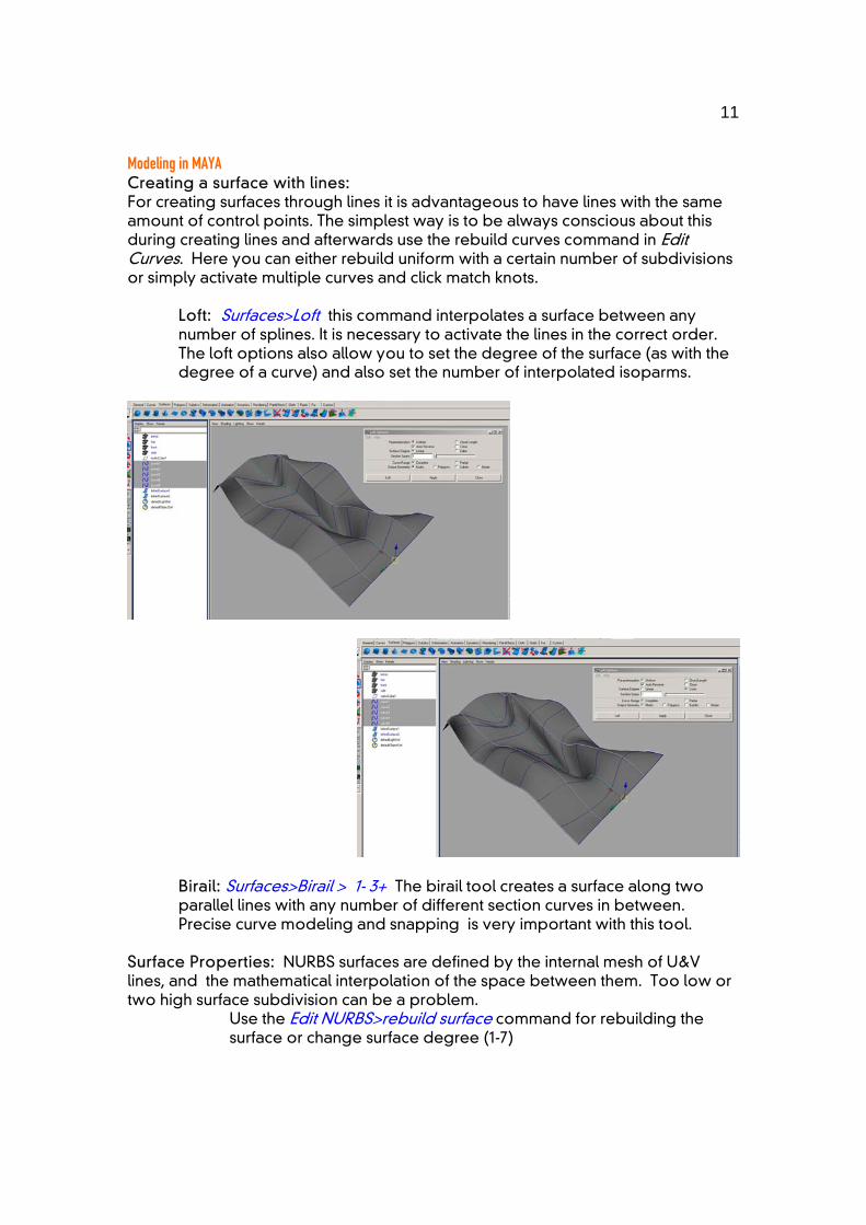
Loft: Surfaces>Loft this command interpolates a surface between any number of splines. It is necessary to activate the lines in the correct order. The loft options also allow you to set the degree of the surface (as with the degree of a curve) and also set the number of interpolated isoparms.
Birail: Surfaces>Birail > 1- 3+ The birail tool creates a surface along two parallel lines with any number of different section curves in between. Precise curve modeling and snapping is very important with this tool.
Surface Properties: NURBS surfaces are defined by the internal mesh of U&V lines, and the mathematical interpolation of the space between them. Too low or two high surface subdivision can be a problem.
Use the Edit NURBS>rebuild surface command for rebuilding the surface or change surface degree (1-7)
12
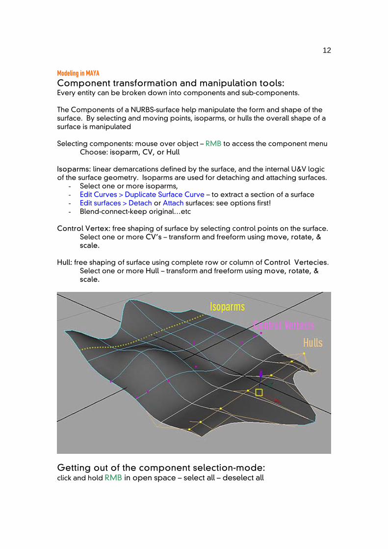
Modeling in MAYA Component transformation and manipulation tools: Every entity can be broken down into components and sub-components. The Components of a NURBS-surface help manipulate the form and shape of the surface. By selecting and moving points, isoparms, or hulls the overall shape of a surface is manipulated
Selecting components: mouse over object – RMB to access the component menu
Choose: isoparm, CV, or Hull Isoparms: linear demarcations defined by the surface, and the internal U&V logic of the surface geometry. Isoparms are used for detaching and attaching surfaces.
- Select one or more isoparms, - Edit Curves > Duplicate Surface Curve – to extract a section of a surface - Edit surfaces > Detach or Attach surfaces: see options first! - Blend-connect-keep original…etc
Control Vertex: free shaping of surface by selecting control points on the surface.
Select one or more CV’s – transform and freeform using move, rotate, & scale.
Hull: free shaping of surface using complete row or column of Control Vertecies. Select one or more Hull – transform and freeform using move, rotate, & scale.
Getting out of the component selection-mode: click and hold RMB in open space – select all – deselect all
13
Modeling in MAYA Suggested Further Personal Research:
- All the tools in the “Edit Curves” menu - all the tools in the “Surfaces” and “Edit Nurbs” menus
- Advanced surface manipulation:
Edit Nurbs>Sculpt Surfaces Tool - Surface qualities and materials:
Window>Rendering Editors>Hypershader
- Lights and Cameras: Create>Light (and then set its attributes) Create>Camera
(and then view the scene by toggling to it with Panel>Perspective)
- Output for print and animation: Window>Rendering Editors>Render View ++Render Globals (button)
- Animations: 1. The time slider bar and setting key frames 2. Programming expressions
- Deformation - using lattice box and manipulators - Dynamics: 1. Ridged and soft-body deformation 2. Particles and particle motion 3. Forces and fields
And above all: Review the Help > Learning Tutorials
14
Programming in MEL for MAYA MEL = MAYA Embedded Language This brief handout gives a short introduction to PROGRAMMING in MAYA. By using MEL to create, modify, and process geometry the users is capable of creating PARAMETRIC SCRIPTS to define a design. These scripts can then be called again and again with different numerical parameters to create different INSTANCES of a design. This guide is intended as a very basic introduction. Programming in MAYA is greatly assisted by the fact that all actions are recorded as MEL script while using the regular GUI interface. As a result it is a simple to begin the programming process. To develop more advanced programming skills, the basic concepts and structures of programming should be learned and experimented with. For a more complete overview of how MEL can be used within MAYA please visit the ALIAS/WAVEFRONT website: www.aliaswavefront.com
HELP ON MEL – working examples The “Help on MEL” MENU-drop down in the SCRIPT EDITOR accesses an off-line html based help session. This session is an excellent starting point for learning the basics of MEL and how to structure MEL scripts. MEL file types : .txt – for the basic editing and creation of MEL files
.mel – MAYA programming (scripting) language file - really only a text file.
.mb – default: MAYA binary
.ma – MAYA ascii (for exchange with other MAYA versions)
15
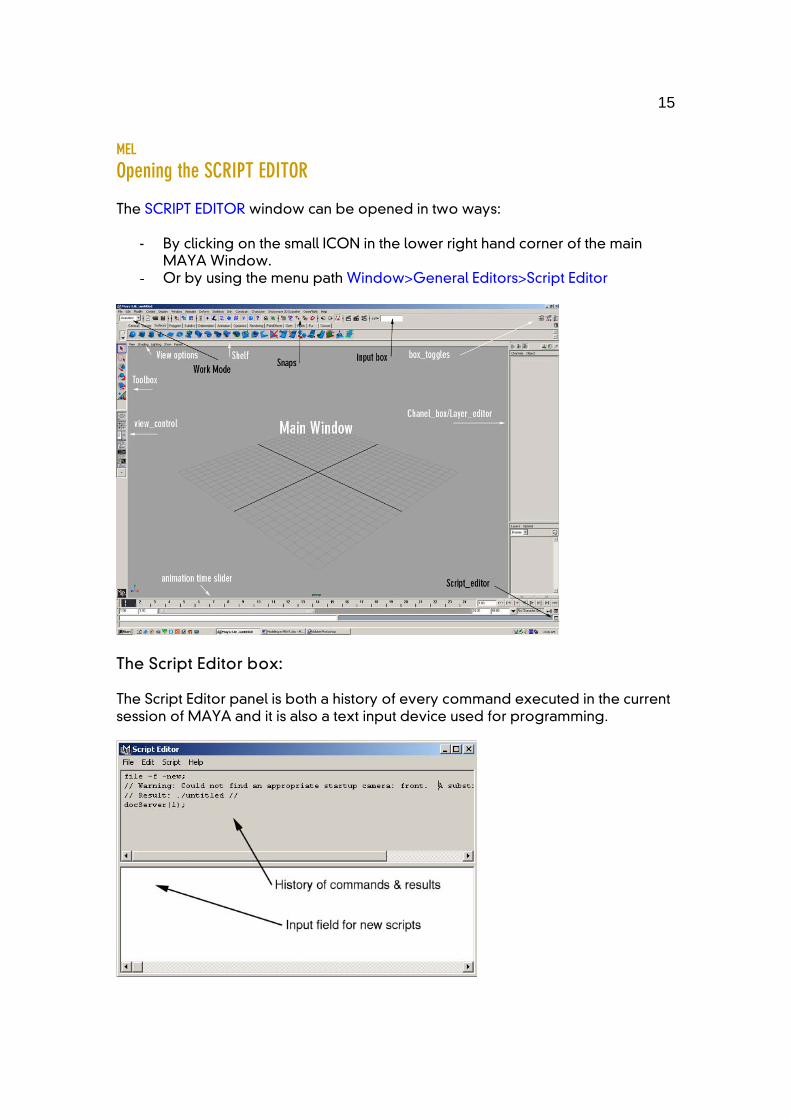
MEL Opening the SCRIPT EDITOR The SCRIPT EDITOR window can be opened in two ways:
- By clicking on the small ICON in the lower right hand corner of the main
MAYA Window. - Or by using the menu path Window>General Editors>Script Editor
The Script Editor box: The Script Editor panel is both a history of every command executed in the current session of MAYA and it is also a text input device used for programming.
16
MEL
Using the Script Editor The Script editor is a record of every command that has been actively executed in the current session of MAYA. The “history” panel displays the executed commands and the Input field allows for manual input of new commands. Whenever a command is called from the GUI the related script including the parametric variables is written into the history field. This fact makes programming in MEL as simple as “CUT – EDIT - PASTE”. - File Open Script: Loads the contents of a text file into the script editor. Source Script: Executes the contents of a text file. When you source a MEL script, local procedures are not declared or executed. If you change a script after sourcing it, the change is not automatically picked up by Maya. You need to re-run the script with File > Source Script. Save Selected: Saves the selected text to a text file. Save to Shelf: Adds a button to the current shelf which executes the script. - Edit Clear History: Clears the top pane of the script editor. Clear Input: Clears the bottom pane of the script editor. Clear All: Clears both the top and bottom panes of the script editor. - Script Execute: Runs the text in the bottom pane of the script editor. You can also press Enter on the numeric keypad. Shortcut > ctrl+ENTER Show Stack Trace: Opens another window which lists errors and their line numbers in external script files. This is very useful for debugging scripts in external files. - Help Help on MEL: A searchable guide on the use of MEL that includes examples of expressions and programming structures MEL command reference: A searchable dictionary of all the commands available in MEL, all of their programming parameters, and some examples. Finally if you want to find out anything about any MEL command all you need to do is type in the input field.: help “command name” (ctrl+enter) The script editor will then show the syntax structure for the command and all of the different parameters and flags that may be set for it. Ex: help nurbsCube; This gives all the parameters that can be set to create a NURBS cube.
17
MEL
Scripting Reading computer programming is not intuitive or clear for most users. However it become s much easier with practice and experimentation.
Basic Workflow Use the GUI to create the basics for a script,
- copy and paste the MEL code into a script editor, & - edit the script. - paste the script back into the MAYA script editor - execute it.
Semi-colon The first rule of organization is that every statement in MEL must end with a semi-colon (;), even at the end of a block. if ($a > $b) {print("Hello"); }; // Both semicolons are required! The organization and the liberal use of COMMENTS assists greatly in the readability of scripts and computer code.
Comments Comments are used within a script as guides to help both yourself and others understand your script. Comments and organizational spacing are the best methods for making your scripts legible. MEL uses C++ style single-line comments identified with two backslashes ( // )at the head of the text string. Ex: //this is a comment Freeform comments surrounded by /* and */. Ex: /*this is a freeform comment That extends over several lines and Doesn’t end until the user Types in the closing indicator */ Comments are a very helpful tool while DE-BUGGING,
- They can be used to help the user keep track and understand what is going on,
- They can be used to tell the script to disregard a line of code. - They can be used to mark specific points in the script - They can be used in combination with the print command to make sure that
any variable output from a particular line is as expected.
18
MEL Variables VARIABLES in computer programming are undefined placeholders in equations that are given value based on prior calculations or input parameters. Variable names in MEL start with a $, followed by a letter, then any combination of letters, numbers, and underscores. MEL has 5 different variable types: Integer: int $a = 5; (Any whole number) floating point: float $b = 3.456; (Any number including fractions) vector: vector $v = <<1.2, 3.4, 6.5>>; (An array of 3 related float values) array: float $ar[] = {1.2, 3.4, 4.5}; (An array of specified number of float values) matrix: matrix $mtx[3][2]; (A multi dimensional matrix of float values) Variables can be defined or assigned a value at the head of a script, they can be defined by an algorithm, or they can be changed using special programming MEL nomenclature. Ex1: int $a = 5; Ex2: float $b = (5+9); Ex3: int $a = 0++;
Organizational structure Scripts that are written with well organized structure are much easier to read and debug. By using “tabs” to space out a hierarchical structure and make single or multiple-nested block of code easier to identify the structure of the script is revealed. Ex:
for ($i=0; $i<30; $i++) {
DO THIS SET OF COMMANDS if($x1>$x2)
{ THEN ALSO DO THIS; }; THEN ALSO DO THIS
}; THEN GO BACK TO THE BEGINNING AND CHECK AGAIN….
Different TEXT EDITORS (such as Ultra_Edit) can help with the proper organization of a script. Most editors will allow you to turn on “line numbering” so as to help with debugging. Also many editors automatically will space and tab blocks of code, and others will identify code with different colours.
19
MEL Looping and logical statements Looping statements use logical operators to control the flow of equations. Logical operators are functions that happen if a condition is met, or if it is not met. For loops For a logical conditions do this and then return to check the condition again. For loops are the most common way to control repetitive operations. If - Else: If something is true then do this,… Else do that. A multiple condition statement can be compared by using If,…. Else If,…. Else If,…. Else…. While clause While “something is true” do this, otherwise disregard the statement and continue below.
Random Number Generators Random numbers are PROBABILITY values that are generated by the computer:
- between 0 and a value - or between two given values. - The return from a “rand” is always a float variable. -
Ex: rand(100) //This command will return a value somewhere between 0 and 100. Ex: rand(50,100) //This command will return a value somewhere between 50 and 100. The sphere-rand command will generate a random vector value (x,y,z). Ex: sphrand(1) this will return a vector value -
// Result: <<0.59872, 0.35843, 0.2859, >> // Often when scripting it is interesting to use RANDOM numbers, so as to add a degree of uncertainty to the code. Random numbers can add to the “look” of complexity and can create unexpected instances and results within geometry….. HOWEVER… Care should be taken when using random numbers in design. Any good, complex, design solution should be under the control of the designer. Random numbers are never predictable or “designed”. An arbitrary value in a code should be justifiable within the logic of the overall designed solution. Scripting is a tool that allows designers to create precise parametric instances of a single set of rules, & the introduction of random values into a code often detracts from the precision & logic of the solution, as well as the design.
20
MEL
Procedures User defined FUNCTIONS are called PROCEDURES. To make workflow more efficient it is advisable to use procedures to combine a series of commands into a single command. In other programming languages procedures are sometimes called SUBROUTINES. Like any function in MEL, a procedure can take any number of parameters (including no parameters), perform calculations, and return a value or geometry. Procedures can be defines as:
- LOCAL PROCEDURES (only available within that script) or - GLOBAL PROCEDURES (available for the duration of that MAYA session).
The ability to set up a procedure that includes user input variables is the first step to programming parametric geometrical output. The ability to call the same procedure again and again, each time inputting different values for the parameters, is the basis or MASS CUSTOMIZATION.
This ability to program a PARAMETRIC design solution for a given problem, and then output a infinite series of design solutions, is the basic design goal of the course. Please Remember: This document is simply a starting guide to assist students to get into MEL and MAYA programming quickly. The ONLY way to become proficient in any software is to use it and work with it regularly.
HELP on MAYA & MEL The HELP files and instructions are especially good in MEL and MAYA, please consult them regularly. This guide begins the learning path for MEL, follow up by reading the HELP ON MEL section of instructions in MAYA.
Problem solving hierarchy:
- Look at your problem again and try to find any “bugs”, spelling errors, or problems with your logic.
- Ask a classmate to look over your script. - Ask a different classmate to look at your script. - Consult the help files on MEL - Consult the on-line MAYA help at www.aliaswavefront.com - If all else fails ask your Teaching Assistant or Tutor
Good Programming!!!