Model YD Dual Centrifugal Compressor Liquid ChillersModel YD Dual Centrifugal Compressor Liquid...
58
Model YD Dual Centrifugal Compressor Liquid Chillers Design Level C FORM 160.69 EG3 (1111) 1500 THROUGH 6000 TONS (5265 through 21096 kW) Utilizing HFC-134a
Transcript of Model YD Dual Centrifugal Compressor Liquid ChillersModel YD Dual Centrifugal Compressor Liquid...

Model YD Dual Centrifugal Compressor Liquid Chillers Design Level C
FORM 160.69 EG3 (1111)
1500 THROUGH 6000 TONS(5265 through 21096 kW)
Utilizing HFC-134a

JOHNSON CONTROLS2
FORM 160.69 EG3 (1111)
FORM 160.69 EG3 (1111) ...................................................................................................................................................................................... 1Introduction ........................................................................................................................................................................................................... 3Sustainability Focus............................................................................................................................................................................................. 5OptiView Control Center ...................................................................................................................................................................................... 7Mechanical Speci cations ................................................................................................................................................................................. 14
ccessories and Modi cations ......................................................................................................................................................................... 17Application Data ................................................................................................................................................................................................. 20Unit Dimensions - English ................................................................................................................................................................................. 30Nozzle Arrangements Dimensions - English ................................................................................................................................................... 32Weights - English ............................................................................................................................................................................................... 38Unit Dimensions - SI ........................................................................................................................................................................................... 40Nozzle Arrangements Dimensions - SI ............................................................................................................................................................. 42Weights - SI ......................................................................................................................................................................................................... 48Component Dimensions .................................................................................................................................................................................... 49Guide Speci cations .......................................................................................................................................................................................... 52SI Metric Conversions ........................................................................................................................................................................................ 57
–
Table of Contents

FORM 160.69 EG3 (1111)
3JOHNSON CONTROLS
The YORK® YDTM chillers offer a complete combination of features for total owner satisfaction. The YD line of chillers utilize two York centrifugal compressors operating in par-allel on a common set of heat exchanger shells to obtain
MATCHED COMPONENTS MAXIMIZE EFFICIENCY
-pressor, and motor performance to achieve the lowest
conditions.
REAL WORLD ENERGY PERFORMANCE
-
on chiller performance during off design conditions. Off
with reduced entering condenser water temperatures
and where operating costs add up.
-
--
sor. The two compressors share a common refrigerant -
able for part load single compressor operation.
-
OPEN DRIVE DESIGN
Hermetic-motor burnout can cause catastrophic dam age to a chiller. The entire chiller must be cleaned, and the re-frigerant replaced. YORK YD centrifugal chillers eliminate
comes in contact with the motor, preventing contamination of the rest of the chiller.
-
tioning equipment often consider air-cooled mo tors a sig-
of a motor used on an equivalent size single compressor
in-rush current of each smaller motor is less. This provides
of two smaller motors allows low voltage compressor drive motors to be applied on larger chillers. This can be an advantage for applications where medium voltage power sources are not available.
HIGH-EFFICIENCY HEAT EXCHANGERS
-
and tube fouling.
SINGLE-STAGE COMPRESSOR DESIGN AND EFFICIENCY PROVEN IN THE MOST DEMANDING APPLICATIONS
Designed to be the most reliable chillers we’ve ever made, YORK YD centrifugal chillers incorporate single
and in other applications where minimal downtime is a crucial concern.
-
-
operation in air conditioning applications.
PRECISION CONTROL OF COMPRESSOR OIL PRESSURE
of the pump rather than at the compressor, and allows
feature two variable speed drive oil pumps, monitoring and
on a continuous basis. This design also provides sophisti-cated electronic monitoring and protection of the oil pump
Introduction

JOHNSON CONTROLS4
FORM 160.69 EG3 (1111)
speed required, rather than at full head with a pressure
FACTORY PACKAGING REDUCES FIELD LABOR COSTS
YORK YD centrifugal chillers are designed to keep in-
-
to K7 compressor size units are disassembled into four
-ing connections are simple plug connections to ensure a simple chiller commissioning process on site.
TAKE ADVANTAGE OF COLDER COOLING TOWER WATER TEMPERATURES
YORK YD centrifugal chillers have been de signed to take full advantage of colder cooling tower water temperatures,
chillers require.
U.L. ACCEPTANCE – YOUR ASSURANCE OF RELIABILITY
YORK YD centrifugal chillers are approved for listing
-
operation.
COMPUTERIZED PERFORMANCE RATINGS
heat exchanger tube bundle sizes and pass arrangements are available to provide the best possible match.
pass arrangement. Computerized ratings are available
OFF DESIGN PERFORMANCE
at off-design conditions, a chiller should be chosen not
-
to an owner’s operating budget, this informa tion has now
-vide a more accurate indication of chiller performance than
Introduction
FORM 160.69 EG3 (1111)
5JOHNSON CONTROLS
Sustainability Focus
OZONE-DEPLETION POTENTIAL (ODP)
-
presence is nevertheless vital to human well-being. Most ozone resides in the upper part of the atmosphere. This
which shields us from harmful ultraviolet radiation from
-
focused on gaining a better understanding of this threat
Monitoring stations showed that ozone-depleting chemi-
trends were linked to growing production and use of
and air conditioning, foam blowing, and industrial clean-
characterized the chemical reactions that were involved
information could predict how much ozone depletion was occurring and how much more could occur in the future.
was indeed occurring. The most severe and most surpris-ing ozone loss was discovered to be recurring in spring-
has been observed over other regions of the globe, such as the Arctic and northern middle latitudes. The work of
most important, we know that if ozone-depleting gases were to continue to accumulate in the atmosphere, the
response to the prospect of increasing ozone depletion,
this global issue. As a result of the broad compliance with
total global accumulation of ozone-depleting gases has slowed and begun to decrease. This has reduced the risk of further ozone depletion.
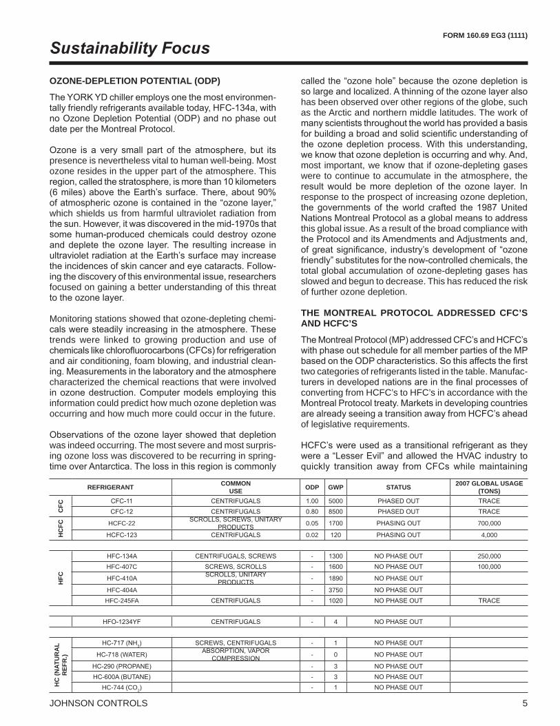
THE MONTREAL PROTOCOL ADDRESSED CFC’S AND HCFC’S
two categories of refrigerants listed in the table. Manufac-
converting from HCFC’s to HFC’s in accordance with the
of legislative requirements.
REFRIGERANT COMMONUSE ODP GWP STATUS 2007 GLOBAL USAGE
(TONS)
CFC
5000
HC
FC HCFC-22 0.05 700,000
0.02 4,000
HFC
- 250,000HFC-407C -
-
HFC-404A - 3750HFC-245FA -
- 4
HC
(NAT
UR
AL
REF
R.)
3 -
- 0
- 3- 3
HC-744 (CO2 -

JOHNSON CONTROLS6
FORM 160.69 EG3 (1111)
out.
for the same reason.
-ant in tons is shown in the table on pg 5.
until the phase-out of HCFC’s. GLOBAL WARMING POTENTIAL (GWP)
However, when we talk about the direct impact our YORK YD Centrifugal Chiller has on the environment we can make strides forward, like ensuring leak tight designs are created, and manufacturers are working to reduce refrigerant charges as much as possible.
DIRECT & INDIRECT GLOBAL WARMING POTENTIAL
is from the indirect effect or the greenhouse gases pro-
gases into the atmosphere.
Minimizing the total climatic impact (direct and indirect
choice.
������
�������
�
�������
�
�������
������
��������
�
�������
�
��������
�
�������
�
������
������
��������
�
�������
�
��������
�
������
��������
�
�������
�
�������
������
�������
�
� ����������
�
�������
������
������
�������
�������
������
� ���������
���
��
��
�
���
��
���������� ���
��
����������������
�� �!� "� �#$����%��! �&�!'�������� �$��(!�"�!����)����*���� ����*��
+ )���������������
,)-! ��)$�!(���()� ��%.
������"! ��
/!� �� ! ����!�������-���0*�1"� �&���
,)-! ��)�.�(�������� �.! )2��3 �(�%.�3����

FORM 160.69 EG3 (1111)
7JOHNSON CONTROLS
YD OPTIVIEW CONTROL CENTER
The YORK OptiView Control Center, furnished as stan-
monitoring, data recording, chiller protection and operating
animated illustration of the appropriate component, which
development makes chiller operation quicker and easier
The use of on-screen animation enables operators to more -
operation of the chiller as well as the present operation.
-
changes of setpoints. This is accomplished with three different levels of access and passwords for each level.
-mable setpoints and manual controls not shown that are
Advanced Diagnostics and troubleshooting information for the chiller and the panel.
-
standard.
The panel is fused through a 2 KVA transformer in the -
dividual over current protected power for all controls.
of each transducer is a DC voltage that is analogous to the pressure input. The output of each thermistor is a DC voltage that is analogous to the temperature it is sensing.
-
which can be mounted inside the Control Center.
OptiView Control Center

JOHNSON CONTROLS
FORM 160.69 EG3 (1111)
This printed circuit board requests the required data from the Microboard and makes it available for the Johnson
-
group. The operating program is stored in non volatile
-ticated program and sensor will monitor the chiller water
countdown timer messages so the operator knows when
point has a pop up screen with the allowable ranges, so that the chiller can not be programmed to operate outside of its design limits.
HOME screen
of the chiller and a collection of data detailing important
shades of color moving in and out of the pipe nozzles. The
Display Only
are the SYSTEM, EVAPORATOR, CONDENSER, COM-PRESSOR, OIL SUMP, MOTOR, SETPOINTS and the HISTORY. Log IN, Log Out and Print.
The SYSTEM screen gives a general overview of common chiller parameters for both shells. This is an end view of
Display Only
The EVAPORATORchiller evaporator. All setpoints relating to the evaporator side of the chiller are maintained on this screen. Animation of the evaporation process indicates whether the chiller is
RUN
interrupted shutdown will occur after a minimum of two
Display Only
Restart
OptiView Control Center - continued

FORM 160.69 EG3 (1111)
JOHNSON CONTROLS
Programmable
-down
The CONDENSER
condenser side of the chiller are maintained on this screen.
Display Only
The COMPRESSORboth compressors; this reveals the impellers and shows
the compressor impeller is spinning, this indicates that the
-
Display Only
The OIL SUMPchiller oil sump and provides access to each individual oil
Display Only
ProgrammableManual Pump -tailed view of each oil pump and provides the setpoints
The MOTOR-
The ELECTRO MECHANICAL STARTER – (E M) screen
Display Only
Programmable
The SETPOINTS screen provides a convenient location for programming the most common setpoints involved in the chiller control. The setpoints are shown on other individual
-
JOHNSON CONTROLS
FORM 160.69 EG3 (1111)
Display Only
Restart
Programmable
Restart
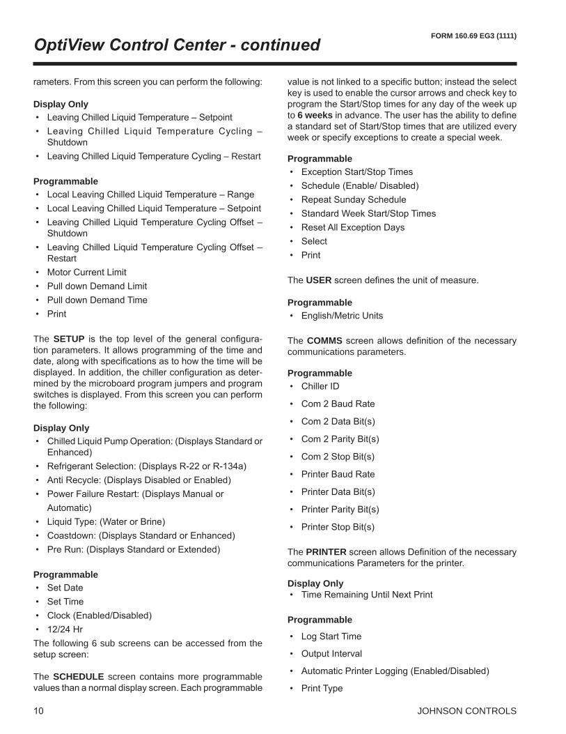
The SETUP -
-
Display Only
Programmable
The following 6 sub screens can be accessed from the
The SCHEDULE screen contains more programmable
to 6 weeks
Programmable
The USER
Programmable
The COMMScommunications parameters.
Programmable
The PRINTER
Display Only
Programmable
OptiView Control Center - continued

FORM 160.69 EG3 (1111)
JOHNSON CONTROLS
The SALES ORDER
Display Only
The OPERATIONS
Remote.
Programmable
The HISTORY screen allows the user to browse through
the conditions while the chiller is running or stopped. The
at a glance, recording the date, time and description.
Display Only
Programmable
VIEW DETAILSHISTORY DETAILS
-eters at the time of the selected shutdown.
Display Only
Programmable
Also under the History screen is the TRENDING screen,
up to 6 operator selected parameters selected from a list
The single screen collects data for one screen width (450
screen keeps collecting the data but the oldest data drops off the graph from left to right at the next data collection
title and associated Y axis labeling is color coordinated.Display Only
to the graph setup screens.
Programmable
The TREND SETUP -ing screen. The parameters to be trended are selected
in the operating manual. The interval at which all the parameters are sampled is selected under the Collection
viewing resolution.Programmable

JOHNSON CONTROLS
FORM 160.69 EG3 (1111)
The TREND COMMON SLOTS
Display Only
Programmable
DISPLAY MESSAGES
-
a message describing the operating state of the chiller; whether it is stopped, running, starting or shutting down.
include a countdown timer indicating the time remaining.
-
Status Messages include:
Run Messages include:
Start Inhibit Messages include:
Warning Messages include:
Routine Shutdown Messages include:
Cycling Shutdown Messages include:
for both oil pumps
Safety Shutdown Messages include:
contacts
OptiView Control Center - continued

FORM 160.69 EG3 (1111)
JOHNSON CONTROLS
both sensors
probes
both probes
probes

JOHNSON CONTROLS
FORM 160.69 EG3 (1111)
GENERAL
--
center, and all interconnecting unit piping and
disassembled for shipment.
The initial charge of refrigerant and oil is supplied for each chiller. Actual shipping procedures will depend on
service representative are incurred to supervise or perform
concurrent operator instructions.
COMPRESSOR
is removable from the compressor and scroll housing.
drive shaft and impeller shaft with a high strength, cast
-anced and overspeed tested for smooth, vibra tion free operation.
with crowned teeth are designed so that more than one tooth is in contact at all times to provide even distribu-
impeller and motor forces.
CAPACITY CONTROL
vane position to maintain a constant leaving chilled liquid tempera ture. Rugged airfoil shaped cast manganese
-ages connected to the electric actuator.
-
LUBRICATION SYSTEM
--
the top of each compressor to provide lubrication during coast down in the event of a power failure.
A common oil reservoir is mounted below the dual com-
removable cover, one at each end of the reservoir.
-
controlled from the sump oil temperature sensor.
A refrigerant cooled oil cooler is provided after each
MOTOR DRIVELINE
The compressor motors are open drip-proof, squirrel cage,
60 hertz motors operate at 3570 rpm. 50 hertz motors
mounted to a cast iron adaptor mounted on the compres-
of motor and compressor shafts.
construction with no wearing parts to assure long life, and no lubrication requirements to provide low maintenance.A large, steel terminal box with gas keted front access
-
brought through the motor casing into the terminal box. -
transformers are furnished with all units.
Mechanical Speci cations

FORM 160.69 EG3 (1111)
JOHNSON CONTROLS
HEAT EXCHANGERS
Shells
rolled carbon steel plates with fusion welded seams. Carbon steel tube sheets, drilled and reamed to accom-modate the tubes, are welded to the end of each shell.
steel plates, drilled and reamed to eliminate sharp edges, and spaced no more than four feet apart. The refrigerant side of each shell is designed, tested, and stamped in
as appropriate.
Tubes
-timum performance. Tubes in both the evaporator and
surface at each intermediate tube support. This provides
hardened copper at the support location, extending the
into the tube sheets providing a leak proof seal, and is
Evaporator-
changer. A distributor trough provides uniform distri bution
heat transfer. Mesh eliminators are located above the
-termining proper refrigerant charge. The evaporator shell
Condenser
is located at the bottom of the condenser shell providing
Water BoxesThe removable water boxes are fabricated of steel. The
-plings grooves are welded to the water boxes. These
-
in each water box.
WATER FLOW SWITCHES
wired to the OptiView control panel. These solid state
high working pressures.
REFRIGERANT FLOW CONTROL
-
subcooler, condenser and evaporator performance. The -
COMPRESSOR DISCHARGE VALVES
Automated valves are provided in the discharge of each compressor. The discharge valve ensures that there is no backspin of the non running compressor when the chiller is in single compressor operating mode. These valves
sequence of the lag (2nd
CODES AND STANDARDS
Refrigeration-
nated Refrigerants in Refrigeration and Air Condition-

JOHNSON CONTROLS
FORM 160.69 EG3 (1111)Mechanical Speci cations - continued
ISOLATION MOUNTING
The unit is provided with four vibration isolation mounts
on the tube sheets.
REFRIGERANT CONTAINMENT
The standard unit has been designed as a complete and
-
to shipment. The YORK chiller includes service valves
condenser isolation valves allow storage of the charge in the condenser.
PAINT
paint.
SHIPMENT
-sembled for shipment. The two drivelines are removed and skidded. The evaporator and condenser shells are split. The control center, oil pump panel and wire remain mounted on the evaporator shell. The oil sump housing re-mains attached to the condenser. Connections are closed and the heat exchanger refrigerant sides are charged with
covered with shrink wrap plastic.

FORM 160.69 EG3 (1111)
JOHNSON CONTROLS
BAS REMOTE CONTROL
A communication interface permitting a exchange of chiller
® ® -
commands to the chiller to control operation.
FACTORY INSULATION OF EVAPORATOR
va por-proof cement to the evaporator shell, tube sheets,
tubing. Not included is the insulation of waterboxes and
-
WATER FLANGES
not included.
SPRING ISOLATION MOUNTING
isolation mounting pads when desired. Four level-ad-
ELECTRO-MECHANICAL STARTER - (FIELD-INSTALLED)
the two compressor motors per chiller.
A. Characteristics For comparison purposes, here is a description of some of the general characteristics of electromechanical start-
all centrifugal chillers required the use of starters using electro-mechanical contactors, which are limited to oper-
starting, regardless of variations in line voltage or motor
with the addition of transformers, reactors, resistors and
electro-mechanical compressor motor starter is available,
The most common failure mode of mechanical contactors is OFF. This occurs due to the coil open-circuiting or failure of a pole to make an electrical contact when it closes. How-
Accessories and Modi cations
TABLE 1STARTER OPTIONS LOW VOLTAGE / FREQUENCY
LV ACROSS THE LINE (DOL)
(FLOOR MOUNTED)
60HZ 50HZ200V 230V 240V 440V 460V 575V 600V 346V 400V 440V
LV STAR-DELTA CLOSED
(FLOOR MOUNTED)
60HZ 50HZ200V 230V 240V 440V 460V 575V 600V 346V 400V 440V
STARTER OPTIONS MV ACROSS THE
LINE (DOL)(FLOOR MOUNTED)
60HZ 50HZ2300 3300 4000 6600 2300 3000 3300 6600
Y Y Y Y Y Y
MV AUTOTRANS-FORMER 65%
(FLOOR MOUNTED)
60HZ 50HZ2300 3300 4000 6600 2300 3000 3300 6600
Y Y Y Y Y Y
MV AUTOTRANS-FORMER 80%
(FLOOR MOUNTED)
60HZ 50HZ2300 3300 4000 6600 2300 3000 3300 6600
Y Y Y Y Y Y

JOHNSON CONTROLS
FORM 160.69 EG3 (1111)
this failure mode exists at the same time that equipment
maximum value from zero, but when contacts are sepa-
and causes an arc. This arcing depends upon the voltage between the separating contacts. For medium voltage the use of vacuum contactors mitigates this problem
-
if one contact has zero current when opened, the other
broken, the voltage is increased at the contacts due to
rises from zero to the maximum of the circuit, or higher
B. Types YORK chillers are designed for use with the following
scribed.
Across-the-Line (ACL)
-
starter for chiller-size motors because of their large cur-rent draw on startup.
Auto-Transformer (AT)voltage starters. Transformers are used to step down the voltage to the motor during startup. The result is reduced
-
torque requirements are low enough to allow the motor
SPECIAL MOTORS ENCLOSURES
comfort cooling plants, and process applications, where -
Weather-Protected Type I Motors (WP-I) -
tilating passages constructed to prevent the passage of
grime is present.
Weather-Protected Type II Motors (WP-II)
passages at both intake and exhaust so arranged that
motor, can be discharged without entering the internal
Totally Enclosed Fan-Cooled Motors (TEFC)
fan-cooled unit is enclosed to prevent the free exchange of air between the inside and outside of the case but not suf-
on the motor shaft.
Totally Enclosed Air-to-Air Cooled (TEAAC)-
exchanger.
Totally Enclosed Water-to-Air Cooled (TEWAC)
corrosive, in hazardous areas, or where minimum noise
an internal water-cooled heat exchanger for cooling the internal air and fans, integral with the rotor shaft for circulating the internal air.

FORM 160.69 EG3 (1111)
JOHNSON CONTROLS
FIGURE 1
MARINE WATER BOXES
Marine water boxes allow service access for cleaning of the heat exchanger tubes without the need to break the water piping. Bolted-on covers are arranged for conven-
-
KNOCK-DOWN SHIPMENT
convenient for existing buildings where equipment room
REFRIGERANT ISOLATION VALVES
of the refrigerant charge in the chiller condenser during servicing, eliminating time consuming transfers to remote storage vessels. Both valves are positive shut off, assuring
REFRIGERANT STORAGE/RECYCLING SYSTEM
package consisting of a refrigerant compressor with oil
OPTISOUND™ CONTROL
of centrifugal chiller hardware and software that reduces operational sound levels, expands the chiller operating
of the compressor discharge gas and optimizes the dif-
sound levels of the chiller an average of 7 dBA, and up
-
combined with little or no condenser water relief. The elimination of the gas stall condition can also result in
for chiller applications with elevated entering condenser
low load operation with constant condenser temperature. At high head conditions, improved chiller operation is vis-ible at all load points.
OptiSound Control AvailabilityStandard
��������
�����������
������
����������������
������������������

JOHNSON CONTROLS20
FORM 160.69 EG3 (1111)
The following discussion is a user’s guide in the applica-tion and installation of YD chillers to ensure the reliable, trouble-free life for which this equipment was designed.
applications, the Johnson Controls sales repre sentative
of applications.
LOCATION
YD
-porting the operating weight of the unit.
tenance work should be provided all around and above the unit. Additional space should be provided at one end of the unit to permit cleaning of evaporator and condenser
The chiller should be installed in an indoor location where
The dew point temperature in the equipment room must be below the entering condenser water temperature to prevent condensing water vapor inside of the low
cooling sources other than evaporative or closed loop air
temperature control valve to prevent condensation inside
to water vapor condensate are outside of the condenser
include when the condenser water comes from chilled
WATER CIRCUITS
Flow Rate –
-plications are possible, and initial chiller selections should
the rate of fouling in the condenser will increase at lower
Temperature Ranges –
Water Quality – The practical and economical applica-
of heat-resistant scale, sedimentation or organic growth. These will degrade chiller performance and increase
General Piping – All chilled water and condenser water piping should be designed and installed in accordance with accepted piping practice. Chilled water and con-denser water pumps should be located to discharge
water from the evaporator and condenser when the pumps
-tion of strain on chiller components. Hangers must allow
vibration control.
Convenience Considerations – To facilitate the perfor-mance of routine maintenance work, some or all of the
and condenser water boxes are equipped with plugged
and chilled water line as close as possible to the chiller.
servicing.
Connections –
chilled water and condenser water circuits. The connec-
Application Data

FORM 160.69 EG3 (1111)
JOHNSON CONTROLS
TABLE 2
COMP LENGTH (FT)
SHELL CODE
EVAPORATOR FLOW RATE (GPM) SHELL CODE
CONDENSER FLOW RATE (GPM)1 PASS 2 PASS 3 PASS 1 PASS 2 PASS 3 PASS
MIN MAX MIN MAX MIN MAX MIN MAX MIN MAX MIN MAX
K1 18
BB 3770 15080 1885 5345 1257 3510 LB 4983 17957 2492 7091 1661 4762BC 4605 18418 2302 6457 1535 4247 LC 5466 19696 2733 7717 1822 5203BD 5405 21621 2703 7487 1802 4933 LD 5828 21003 2914 8177 1943 5530
B2 3870 15482 1935 6975 1290 4588 L2 4303 15508 2152 7645 1434 5143B3 4603 18413 2302 8166 1534 5384 L3 5072 18278 2536 8886 1691 6031B4 5241 20965 2621 9157 1747 6050 L4 5989 21584 2995 10278 1996 7057
K2
22
MB 3770 15080 1885 4798 1257 3150 MB 4992 17991 2496 6472 1664 4281MC 4605 18418 2302 5809 1535 3818 MC 5466 19696 2733 7056 1822 4672MD 5405 21621 2703 6751 1802 4444 MD 5828 21003 2914 7498M2 3870 15482 1935 6288 1290 4133 M2 4303 15508 2152 7002 1434 4629M3 4603 18413 2302 7383 1534 4862 M3 5072 18278 2536 8205 1691 5438M4 5241 20965 2621 8302 1747 5477 M4 5989 21584 2995 9591
18
NB 4769 19076 2385 6756 1590 4448 BB 6213 22389 3107 8841 2071 5944NC 5272 21087 2636 7430 1757 4897 BC 6740 24287 3370 9524 2247 6426ND 5740 22961 2870 8049 1913 5312 BD 7115 25640 3557 10002 2372 6767
BE 7449 26844 3725 10422N2 4769 19074 2384 8600 1590 5678 B2 5772 20802 2886 10240 1924 6928N3 5637 22549 2819 10018 1879 6637 B3 6380 22991 3190 11206 2127 7627N4 6281 25125 3141 11028 2094 7327 B4 6981 25157 3491 12129 2327 8307
B5 7713 27793 3856 13204
K3
22
EB 6218 24872 3109 7808 2073 5151 CB 6241 22491 3121 7996 2080 5356EC 7006 28025 3503 8725 2335 5768 CC 6967 25105 3483 8855 2322 5956ED 7769 31078 3885 9591 2590 6353 CD 7900 28470 3950 9930 2633 6718
E2 6287 25149 3144 9998 2096 6626 C2 4969 17905 2484 8003 1656 5352E3 6961 27843 3480 10944 2320 7272 C3 6487 23378 3244 10280 2162 6959E4 7670 30680 3835 11905 2557 7933 C4 8099 29185 4049 12516 2700 8601
18
FB 7825 31301 3913 10675 2608 7217 DB 7569 27276 3785 10902 2523 7247FC 8756 35025 4378 11776 2919 8018 DC 8440 30413 4220 12073 2813 8045FD 9699 38798 4850 12843 3233 8813 DD 9326 33607 4663 13240 3109 8847
DE 9714 35004 4857 13742F2 7871 31483 3935 13358 2624 9199 D2 7206 25969 3603 12967 2402 8647F3 8745 34981 4373 14540 2915 10112 D3 7944 28627 3972 14196 2648 9496F4 9703 38811 4851 15751 3234 11079 D4 8756 31553 4378 15512 2919 10414
D5 9909 35708 4954 17309
K4
22
GB 7825 31301 3913 9653 2608 6488 EB 7708 27776 3854 9967 2569 6616GC 8756 35025 4378 10675 2919 7218 EC 8578 30913 4289 11030 2859 7337GD 9699 38798 4850 11673 3233 7945 ED 9465 34107 4732 12094 3155 8062
EE 9853 35505 4926 12553G2 7871 31483 3935 12170 2624 8308 E2 7345 26469 3673 11870 2448 7898G3 8745 34981 4373 13291 2915 9151 E3 8083 29127 4041 12997 2694 8671G4 9703 38811 4851 14453 3234 10048 E4 8895 32053 4447 14208 2965 9508
E5 10048 36208 5024 15874
18
HB 8961 35844 4480 12012 2987 8192 FB 9121 32868 4560 12972 3040 8662HC 9855 39418 4927 13013 3285 8941 FC 10098 36391 5049 14235 3366 9535HD 11009 44035 5504 14241 3670 9884 FD 10865 39153 5432 15201 3622 10209
FE 11281 40000 5641 15716H2 8804 35218 4402 14617 2935 10173 F2 8721 31428 4361 15405 2907 10337H3 9785 39141 4893 15852 3262 11160 F3 9620 34666 4810 16817 3207 11333H4 10873 43490 5436 17118 3624 12210 F4 10605 38218 5303 18307 3535 12397
K7 22
F5 11703 40000 5851 19890KB 8961 35844 4480 10895 2987 7377 KB 10767 38800 5384 13620 3589 9112KC 9855 39418 4927 11834 3285 8063 KC 11969 40000 5984 14985 3990 10061KD 11009 44035 5504 12995 3670 8930 KD 12647 40000 6323 15737 4216 10588
KE 13303 40000 6651 16451K2 8804 35218 4402 13365 2935 9207 K2 9944 35834 4972 15693 3315 10544K3 9785 39141 4893 14550 3262 10124 K3 10961 39497 5480 17114 3654 11549K4 10873 43490 5436 15779 3624 11105 K4 12082 40000 6041 18619 4027 12627
K5 13682 40000 6841 20649

JOHNSON CONTROLS22
FORM 160.69 EG3 (1111)Application Data - continued
TABLE 2A
COMP LENGTH (FT)
SHELL CODE
EVAPORATOR FLOW RATE (LPS) SHELL CODE
CONDENSER FLOW RATE (LPS)1 PASS 2 PASS 3 PASS 1 PASS 2 PASS 3 PASS
MIN MAX MIN MAX MIN MAX MIN MAX MIN MAX MIN MAX
K1 18
BB 238 952 119 337 79 221 LB 314 1133 157 447 105 301BC 291 1162 145 407 97 268 LC 345 1243 172 487 115 328BD 341 1364 171 472 114 311 LD 368 1325 184 516 123 349
N/A N/A N/A N/A N/A N/AB2 244 977 122 440 81 290 L2 272 979 136 482 91 325B3 290 1162 145 515 97 340 L3 320 1153 160 561 107 381B4 331 1323 165 578 110 382 L4 378 1362 189 649 126 445
K2
22
MB 238 952 119 303 79 199 MB 315 1135 158 408 105 270MC 291 1162 145 367 97 241 MC 345 1243 172 445 115 295MD 341 1364 171 426 114 280 MD 368 1325 184 473M2 244 977 122 397 81 261 M2 272 979 136 442 91 292M3 290 1162 145 466 97 307 M3 320 1153 160 518 107 343M4 331 1323 165 524 110 346 M4 378 1362 189 605
18
NB 301 1204 150 426 100 281 BB 392 1413 196 558 131 375NC 333 1331 166 469 111 309 BC 425 1533 213 601 142 406ND 362 1449 181 508 121 335 BD 449 1618 224 631 150 427
BE 470 1694 235 658N2 301 1204 150 543 100 358 B2 364 1313 182 646 121 437N3 356 1423 178 632 119 419 B3 403 1451 201 707 134 481N4 396 1585 198 696 132 462 B4 441 1587 220 765 147 524
B5 487 1754 243 833
K3
22
EB 392 1569 196 493 131 325 CB 394 1419 197 505 131 338EC 442 1768 221 551 147 364 CC 440 1584 220 559 147 376ED 490 1961 245 605 163 401 CD 499 1796 249 627 166 424
E2 397 1587 198 631 132 418 C2 314 1130 157 505 105 338E3 439 1757 220 691 146 459 C3 409 1475 205 649 136 439E4 484 1936 242 751 161 501 C4 511 1842 256 790 170 543
18
FB 494 1975 247 674 165 455 DB 478 1721 239 688 159 457FC 553 2210 276 743 184 506 DC 533 1919 266 762 178 508FD 612 2448 306 810 204 556 DD 588 2121 294 835 196 558
DE 613 2209 306 867F2 497 1987 248 843 166 580 D2 455 1639 227 818 152 546F3 552 2207 276 917 184 638 D3 501 1806 251 896 167 599F4 612 2449 306 994 204 699 D4 552 1991 276 979 184 657
D5 625 2253 313 1092
K4
22
GB 494 1975 247 609 165 409 EB 486 1753 243 629 162 417GC 553 2210 276 674 184 455 EC 541 1951 271 696 180 463GD 612 2448 306 737 204 501 ED 597 2152 299 763 199 509
EE 622 2240 311 792G2 497 1987 248 768 166 524 E2 463 1670 232 749 154 498G3 552 2207 276 839 184 577 E3 510 1838 255 820 170 547G4 612 2449 306 912 204 634 E4 561 2023 281 897 187 600
E5 634 2285 317 1002
18
HB 565 2262 283 758 188 517 FB 576 2074 288 819 192 547HC 622 2487 311 821 207 564 FC 637 2296 319 898 212 602HD 695 2779 347 899 232 624 FD 686 2471 343 959 229 644
FE 712 2524 356 992H2 556 2222 278 922 185 642 F2 550 1983 275 972 183 652H3 617 2470 309 1000 206 704 F3 607 2187 304 1061 202 715H4 686 2744 343 1080 229 770 F4 669 2412 335 1155 223 782
F5 738 2524 369 1255
K7 22
KB 565 2262 283 687 188 465 KB 679 2448 340 859 226 575KC 622 2487 311 747 207 509 KC 755 2524 378 946 252 635KD 695 2779 347 820 232 563 KD 798 2524 399 993 266 668
KE 839 2524 420 1038K2 556 2222 278 843 185 581 K2 627 2261 314 990 209 665K3 617 2470 309 918 206 639 K3 692 2492 346 1080 231 729K4 686 2744 343 996 229 701 K4 762 2524 381 1175 254 797
K5 863 2524 432 1303

FORM 160.69 EG3 (1111)
23JOHNSON CONTROLS
����4�
����4�
�5,�4�
�5,�4�
�
��
��
FIG. 2 – FIG. 3 –
S
T
����4� ����4�
�5,�4� �5,�4�
� �� ��
S
T
COND. 1 COND. 2
EVAP. 1 EVAP. 2
T S1 S2
Chilled Water – A water strainer with perforated holes
located close enough to the chiller, the chilled water pump
-
connected to the OptiView panel, which assures adequate
Condenser Water – The chiller is engineered for maxi-
months. Appreciable power savings are realized from these reduced heads.
The minimum entering condenser water temperature for -
at the given load condition.
At initial startup, entering condensing water temperature
chilled water temperature as long as it is above the mini-
BRINE APPLICATIONS
and condenser in lieu of water. The OptiView panel is pro-
to the appropriate value depending on the percentage
FIG. 4

JOHNSON CONTROLS24
FORM 160.69 EG3 (1111)Application Data - continued
-cations, the condenser pump control will close when the
and the pump will shut off when the temperature increases
pump control.
MULTIPLE UNITS
Selection –
equipment shutdown. There are several common unit ar-YD chiller has
of these various arrangements.
Parallel Arrangement – Chillers
water circuits connected in parallel between the units. Fig. 2 represents a parallel arrangement with two chillers.
full load for the chiller.
Depending on the number of units and operating char-acteristics of the units, loading and unloading schemes
-
Series Arrangement (Refer – Chill-
connected in series and condenser water circuits con-
customer selected load value, one of the units will be shut
through the operating unit, that unit will cool the water to the desired temperature.
(Refer to Fig. 4, pg
circuits connected in series and with the condenser water
both condensers. The water ranges are split, which allows
than multiple units in parallel. For equal chillers, the
-tors and gear codes on the two chillers are often matched, such that the high temperature machine can operate at
off at part loads (as compared to series parallel chillers
have chilled and condenser water temperature ranges
REFRIGERANT RELIEF PIPING
condenser and a single relief valve on the evaporator. The dual relief valves on the condenser are redundant and al-
pressure of the refrigerant charge to the atmosphere, as
noted on the pressure vessel data plate, and are provided
or applicable pressure vessel code.
must run from the relief device to the outside of the build-ing. This refrigerant relief piping must include a cleanable, vertical-leg dirt trap to catch vent-stack con densation. Vent piping must be arranged to avoid im posing a strain on the relief connection and should include at least one
SOUND AND VIBRATION CONSIDERATIONS
A YDvibration in normal air conditioning applica tions. Neoprene isolation mounts are furnished as standard with each
from Johnson Controls.
YD chiller sound pressure level ratings will be furnished on request.
Control of sound and vibration transmission must be taken into account in the equipment room construction as well as in the selection and installation of the equip ment.
THERMAL INSULATION
surfaces should be insulated with a vapor barrier insulation

FORM 160.69 EG3 (1111)
25JOHNSON CONTROLS
for a chiller installed indoors and, therefore, no protective -
be removable to permit access to the tubes for routine maintenance.
VENTILATION
or more power-driven fans. This standard, plus National
ventilation should allow for the removal of heat from the motors.
-
is to be located in an area where refrigerant from a leak
and the mechanical ventilation started at a value no great-
ELECTRICAL CONSIDERATIONS
Motor Voltage –are furnished with six leads. Medium voltage (2300 volts
-
for the last several feet to the chiller in order to provide
vibration isolation. Table 3 lists the allowable variation in voltage supplied to the chiller motor. The unit name plate
for the appropri ate motor.
Starterselectro mechanical starters, one connected to each of
-nished as a package with the two incoming feeds bussed or cabled together. These electro mechanical starters
-ponents, controls, circuits, and terminal markings will be
Controls –
control transformer, included in the 3 phase variable speed
Oil Pump Power Supply
This panel operates the two oil pump motors, powers the 3 phase oil reservoir heater, and includes the control power transformer for the chiller control panel. A common incoming disconnect is provided at the panel. Component
Copper Conductors – Only copper conductors should be connected to compressor motors and starters. Aluminum conductors have proven to be un-
copper and aluminum cannot guarantee the re quired tight connection over a long period of time.
Power Factor Correction Capacitors – Capacitors can be applied to a chiller for the purpose of power factor cor-rection. For remote mounted electro mechanical starters, the ca pacitors should be located on the load-side of the starter. The capacitors must be sized and installed to meet
Controls.
Ampacity on Load Side of Starter – wire size to each chiller motor is based on the minimum
be supplied with the submittal drawings.
TABLE 3 –
FREQ. RATED VOLTAGE
NAME PLATE
VOLTAGE*
OPERATING VOLTAGE
MIN. MAX.
60 HZ
342375 457
460575 520 6352300 2300 2070 25303300 3300 36304000 3600 4576
50 HZ
346 346342 423374 440
3300 3300 3630

JOHNSON CONTROLS26
FORM 160.69 EG3 (1111)Application Data - continued
-
Ampacity on Line-Side of Starter – The YD chiller -
ers are connected together to the line side, the individual
obtain the total. the chiller would be the control transformer and oil pump
Branch Circuit Overcurrent Protection – The branch
calculations for each application.
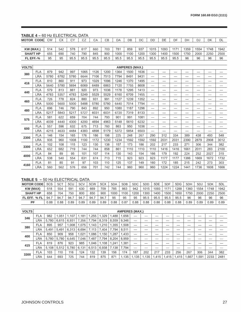
MOTOR ELECTRICAL DATAThe smallest motor available which equals or exceeds
listed in the tables are maximum values and correspond
reduced per the following equation
Tables 4 and 5
voltage and is independent of
starter applied. The in-rush can be calculated using a
FORM 160.69 EG3 (1111)
27JOHNSON CONTROLS
TABLE 4 – MOTOR CODE CY CZ CA CB DA DB DC DD DF DH DJ DK
KW (MAX.) 542 660 703SHAFT HP 655 740 2000 2250 2500FL EFF.-%
VOLTS AMPERES (MAX.)
380— — — — — — —
6644 — — — — — — —
416— — — — — — —
5640 7755 — — — — — — —
440— — — — — — —
5357 7455 — — — — — — —
460726 — — — — — — —5000 5600 5000 6440 — — — — — — —
480746 — — — — — — —
5727 6720 — — — — — — —
575622 704 744 — — — — — — —4440 4300 4200 6232 — — — — — — —
600557 632 675 760 — — — — — — —
4633 5372 6503 — — — — — — —
2300225 267 334
3300202 233 306 344
652 744 744
4000224 252 2027
540 554 674
4160242 273 303
560 562 576 656 742 744
TABLE 5 – MOTOR CODE 5CT 5CV 5DA 5DB 5DC 5DD 5DF 5DH 5DJ 5DK
KW (MAX) 554 630 SHAFT HP 704 750 2000 2250 2500
FL EFF. % FL PF
VOLTS AMPERES (MAX.)
346— — — — — — — — —
7,356 — — — — — — — — —
380— — — — — — — — —
7,404 — — — — — — — — —
400— — — — — — — — —
6,645 7,046 — — — — — — — — —
415— — — — — — — — —— — — — — — — — —
3300202 233 256 267 306 344
644 725 744 2233

JOHNSON CONTROLS
FORM 160.69 EG3 (1111)
NOTE:
Application Data - continued
TABLE 6 – TYPE
STARTERSTAR
DELTA AUTO TRANSFORMER ACROSS THE LINE PRIMARY REACTOR
VOLTAGE60 HZ50 HZ
TRANSITION% TAP
IN-RUSHAS A % OF LRA
—33
57.733
6542.3 64
—— 65
65
TABLE 7 COMPRESSOR CODE EVAPORATOR CODE CONDENSER CODE
MOTOR CODES60 HZ 50 HZ
BB, BC, BD, B2, B3, B4
K2MB, MC, MD, M2, M3, M4 MB, MC, MD, M2, M3, M4
NB, NC, ND, N2, N3, N4
K3CB, CC, CD, C2, C3, C4
DA-DJ 5DA-5DJFB, FC, FD, F2, F3, F4
K4 DA-DJ 5DA-5DJHB, HC, HD, H2, H3, H4
K7 KB, KC, KD, K2, K3, K4

FORM 160.69 EG3 (1111)
JOHNSON CONTROLS
INTENTIONALLY LEFT BLANK

JOHNSON CONTROLS30
FORM 160.69 EG3 (1111)Unit Dimensions - English
K COMPRESSOR UNITS
6.6 " B 4,5
L D C C L C L
0.4 " 9"
5.9 in A
M
SHIPPING WIDTH
CONDENSER
EVAPORATOR
FLOOR LINE

FORM 160.69 EG3 (1111)
JOHNSON CONTROLS
NOTES:
see pages 32-35.
EVAPORATOR - CONDENSER SHELL CODESDIM. B-L M-M N-B E-C F-D G-E H-F K-K
ABCDEFGHJL
NOTE:
ADDITIONAL OPERATING HEIGHT CLEARANCE TO FLOORTYPE OF CHILLER MOUNTING M

JOHNSON CONTROLS32
FORM 160.69 EG3 (1111)Nozzle Arrangements Dimensions - English
EVAPORATORS – COMPACT WATER BOXES
NOTES:
4. Connected piping should allow for removal of compact water boxes for tube access and cleaning.
� � �
�
�
� �
��
����������
B, M, N SHELLS E, F, G, H, K SHELLS
NOZZLE ARRANGEMENTS
NO. OF PASSES
EVAPORATORIN OUT
1A HH A
NOZZLE ARANGEMENTS
EVAP CODESB, M, N E, F,
G, H, KIN OUT IN OUTB C – –C B E BJ K – –K J M J
NOZZLE ARRANGEMENTS
NO. OF PASSES
EVAPORATORIN OUT
3F NN F
EVAP. SHELL CODE
EVAPORATORNOZZLE PIPE SIZE
NO. OF PASSES NOZZLE DIMENSIONS
1 PASS 2 PASS 3 PASS 1-PASS 2-PASS 3-PASS1 2 3 AA2 FF AA BB2 EE FF BB2 EE FF
B,M — —N — —E
F,GH,K

FORM 160.69 EG3 (1111)
33JOHNSON CONTROLS
CONDENSERS – COMPACT WATER BOXES
CONDENSER NOZZLE ARRANGEMENTSNO. OF PASSES
COND.IN OUT
CONDENSER NOZZLE ARRANGEMENTSNO. OF PASSES
COND.IN OUT
2RT
CONDENSER NOZZLE ARRANGEMENTSNO. OF PASSES
COND.IN OUTV Y
COND.SHELL CODE
CONDENSERNOZZLE PIPE SIZE
NO. OF PASSES NOZZLE DIMENSIONS
1 PASS 2 PASS 3 PASS 1 PASS 2 PASS 3 PASS1 2 3 CC2 GG BB2 DD2 GG BB2 DD GG
L, MBC
D, EFK

JOHNSON CONTROLS34
FORM 160.69 EG3 (1111)
�� ����������� ����
��� � �����������
� �
�
EVAPORATORS – MARINE WATER BOXES
Nozzle Arrangements Dimensions - English
EVAP. SHELL CODE
EVAPORATOR NOZZLE DIMENSIONS1 PASS 2 PASS 3 PASS
A5 D A5 B5 C D A5 B5 C DB, M
N E
F, GH, K

FORM 160.69 EG3 (1111)
35JOHNSON CONTROLS
NOTES (see table on page 32):
pipe size, furnished as welding stub outs with grooves, allowing the on, forged carbon steel with
the other heat exchanger.ater must enter the water box through the bottom connection to achieve rated performance.
EVAPORATOR1 PASS
IN OUT6
6
EVAPORATOR2 PASS
IN OUT2 37
EVAPORATOR3 PASS
IN OUT5
4
EVAPORATOR SHELL CODE
NOZZLE PIPE SIZENO. OF PASSES
1 2 3B,MNE
F.GH, K
EVAPORATOR SHELL CODE
DESIGN WORKING
PRESSURE (PSIG)
EVAPORATOR NOZZLE DIMENSIONS (1-PASS)
G H
B,M300
N300
E300
F,G300
H,K300
EVAPORATOR SHELL CODE
DESIGN WORKING
PRESSURE (PSIG)
EVAPORATOR NOZZLE DIMENSIONS (2-PASS)
G H K
B,M300
N300
E300
F,G300
H,K300
EVAPORATOR SHELL CODE
DESIGN WORKING
PRESSURE (PSIG)
EVAPORATOR NOZZLE DIMENSIONS (3-PASS)
G H
B,M300
N300
300
300
H,K300

JOHNSON CONTROLS36
FORM 160.69 EG3 (1111)
CONDENSERS – MARINE WATER BOXES
Nozzle Arrangements Dimensions - English
COND. SHELL CODE
CONDENSER NOZZLE DIMENSIONS1 PASS 2 PASS 3 PASS
A5 D A5 B5 C D A5 B5 C DL, M
BC
D, EFK

FORM 160.69 EG3 (1111)
37JOHNSON CONTROLS
NOTES (see table on page 34):
the other heat exchanger. 4. Condenser water must enter the water box through the bottom connection for proper operation of the sub cooler to achieve rated performance.
CONDENSER1 PASS
IN OUT
CONDENSER2 PASS
IN OUT
CONDENSER3 PASS
IN OUT20
COND. SHELL CODE
NOZZLE PIPE SIZENO. OF PASSES
1 2 3L, M
BC
D, EF, K
CONDENSER SHELL CODE
DESIGN WORKING
PRESSURE (PSIG)
CONDENSER NOZZLE DIMENSIONS (1-PASS)
G H
L,M300
B300
C300
D,E300
F300
K300
CONDENSER SHELL CODE
DESIGN WORKING
PRESSURE (PSIG)
CONDENSER NOZZLE DIMENSIONS (2-PASS)
G H K
L,M300
B300
C300
D,E300
F300
K300
CONDENSER SHELL CODE
DESIGN WORKING
PRESSURE (PSIG)
CONDENSER NOZZLE DIMENSIONS (3-PASS)
G H
L,M300
B300
C300
D,E300
F300
K300

JOHNSON CONTROLS
FORM 160.69 EG3 (1111)Weights - English
TABLE 8 –
SHELLS COMPRESSOR SHIPPING WEIGHT (LBS) **
OPERATION WEIGHT (LBS)
EST. REFRIGERANT CHARGE (LBS) ***
B-L 6,000M-M K2 7,300N-B K2 7,200E-C K3F-D K3G-E K4H-F K4K-K K7 222,200
TABLE 9 –
EVAP CODE
SHIPPING WEIGHT IN-CREASE (LBS)
OPERATING WEIGHT IN-CREASE (LBS) COND.
CODE
SHIPPING WEIGHT IN-CREASE (LBS)
OPERATING WEIGHT IN-CREASE (LBS)
1-PASS 2-PASS 3-PASS 1-PASS 2-PASS 3-PASS 1-PASS 2-PASS 3-PASS 1-PASS 2-PASS 3-PASSB 5520 L 5256M 5520 M 5256N 3604 7244 B 5060E 6554 C F D 6333G E 6333H 22366 20267 F 4643K 22366 20267 K 5520

FORM 160.69 EG3 (1111)
JOHNSON CONTROLS
INTENTIONALLY LEFT BLANK

JOHNSON CONTROLS40
FORM 160.69 EG3 (1111)Unit Dimensions - SI
6.6 " B 4,5
L D C C L C L
0.4 " 9"
5.9 in A
M
SHIPPING WIDTH
CONDENSER
EVAPORATOR
FLOOR LINE

FORM 160.69 EG3 (1111)
JOHNSON CONTROLS
NOTES:1 A C2 F F M B 41 443 A 134 A M 395 U A 150 5DJ
EVAPORATOR - CONDENSER SHELL CODESDIM. B-L M-M N-B E-C F-D G-E H-F K-K
A 3505 3505 3632 4064 4420 4420 4572
BCDE 6706 6706 6706 6706
F 660 635
G 445 464 464
H 305 305
J 660 635
L 2235
NOTE:
ADDITIONAL OPERATING HEIGHT CLEARANCE TO FLOORTYPE OF CHILLER MOUNTING M
4425

JOHNSON CONTROLS42
FORM 160.69 EG3 (1111)
EVAPORATORS – COMPACT WATER BOXES
NOTES:
4. Connected piping should allow for removal of compact water boxes for tube access and cleaning.
� � �
�
�
� �
��
����������
B, M, N SHELLS E, F, G, H, K SHELLS
Nozzle Arrangements Dimensions - SI
NOZZLE ARRANGEMENTS
NO. OF PASSES
EVAPORATORIN OUT
1A HH A
NOZZLE ARANGEMENTS
EVAP CODESB, M, N E, F,
G, H, KIN OUT IN OUTB C – –C B E BJ K – –K J M J
NOZZLE ARRANGEMENTS
NO. OF PASSES
EVAPORATORIN OUT
3F NN F
EVAP. SHELL CODE
EVAPORATORNOZZLE PIPE SIZE
NO. OF PASSES NOZZLE DIMENSIONS
1 PASS 2 PASS 3 PASS 1-PASS 2-PASS 3-PASS1 2 3 AA2 FF AA BB2 EE FF BB2 EE FF
B,M — —N — —E 330 406
F,G 330 406H,K 330 406

FORM 160.69 EG3 (1111)
43JOHNSON CONTROLS
CONDENSERS – COMPACT WATER BOXES
CONDENSER NOZZLE ARRANGEMENTSNO. OF PASSES
COND.IN OUT
CONDENSER NOZZLE ARRANGEMENTSNO. OF PASSES
COND.IN OUT
2RT
CONDENSER NOZZLE ARRANGEMENTSNO. OF PASSES
COND.IN OUTV Y
COND.SHELL CODE
CONDENSERNOZZLE PIPE SIZE
NO. OF PASSES NOZZLE DIMENSIONS
1 PASS 2 PASS 3 PASS 1 PASS 2 PASS 3 PASS1 2 3 CC2 GG BB2 DD2 GG BB2 DD GG
L, M 737 737B 724C
D, E 762FK

JOHNSON CONTROLS44
FORM 160.69 EG3 (1111)
EVAPORATORS – MARINE WATER BOXES
�� ����������� ����
��� � �����������
� �
�
Nozzle Arrangements Dimensions - SI
EVAP. SHELL CODE
EVAPORATOR NOZZLE DIMENSIONS1 PASS 2 PASS 3 PASS
A5 D A5 B5 C D A5 B5 C DB, M 400 400
N 540 540E 2350 2350 2350
F, GH, K

FORM 160.69 EG3 (1111)
45JOHNSON CONTROLS
NOTES (see Table on page 42):
2. pipe size, furnished as welding stub outs with grooves, allowing on, forged carbon steel
furnished.
the other heat exchanger.ater must enter the water box through the bottom connection to achieve rated performance.
EVAPORATOR1 PASS
IN OUT6
6
EVAPORATOR2 PASS
IN OUT2 37
EVAPORATOR3 PASS
IN OUT5
4
EVAPORATOR SHELL CODE
NOZZLE PIPE SIZENO. OF PASSES
1 2 3B,MNE
F.GH, K
EVAPORATOR SHELL CODE
DESIGN WORKING
PRESSURE (KPA)
EVAPORATOR NOZZLE DIMENSIONS (1-PASS)
G H
B,M400
N
E470552
F,G
H,K470546
EVAPORATOR SHELL CODE
DESIGN WORKING
PRESSURE (KPA)
EVAPORATOR NOZZLE DIMENSIONS (2-PASS)
G H K
B,M 343 762375
N343 762
E406445
F,G464
H,K476
EVAPORATOR SHELL CODE
DESIGN WORKING
PRESSURE (KPA)
EVAPORATOR NOZZLE DIMENSIONS (3-PASS)
G H
B,M343 762375
N343 762
362
457
H,K445

JOHNSON CONTROLS46
FORM 160.69 EG3 (1111)
CONDENSERS – MARINE WATER BOXES
Nozzle Arrangements Dimensions - SI
COND. SHELL CODE
CONDENSER NOZZLE DIMENSIONS (mm)1 PASS 2 PASS 3 PASS
A5 D A5 B5 C D A5 B5 C DL, M 660 660
BC 762 762
D,E 2235 2235 2235 737
FK 2477 2477 2477

FORM 160.69 EG3 (1111)
47JOHNSON CONTROLS
NOTES (see Table on page 44):
furnished.
the other heat exchanger. 4. Condenser water must enter the water box through the bottom connection for proper operation of the sub cooler to achieve rated performance.
CONDENSER1 PASS
IN OUT
CONDENSER2 PASS
IN OUT
CONDENSER3 PASS
IN OUT20
COND. SHELL CODE
NOZZLE PIPE SIZENO. OF PASSES
1 2 3L, M
BC
D, EF, K
CONDENSER SHELL CODE
DESIGN WORKING
PRESSURE (KPA)
CONDENSER NOZZLE DIMENSIONS (1-PASS)
G H
L,M
B
C445
D,E476552
F
K470552
CONDENSER SHELL CODE
DESIGN WORKING
PRESSURE (KPA)
CONDENSER NOZZLE DIMENSIONS (2-PASS)
G H K
L,M343 743
305
B343362 343
C400
D,E445
F
K470552 445
CONDENSER SHELL CODE
DESIGN WORKING
PRESSURE (KPA)
CONDENSER NOZZLE DIMENSIONS (3-PASS)
G H
L,M343 743
B343362
C400
D,E
F425502
K

JOHNSON CONTROLS
FORM 160.69 EG3 (1111)Weights - SI
TABLE 10
SHELLS COMPRESSOR SHIPPING WEIGHT (KGS) **
OPERATION WEIGHT (KGS)
EST. REFRIGERANT CHARGE (KGS) ***
B-LM-M K2 37735N-B K2 3266E-C K3F-D K3 4445G-E K4 5533H-F K4 63043K-K K7
TABLE 11 –
EVAP CODE
SHIPPING WEIGHT INCREASE (KGS)
OPERATING WEIGHT INCREASE (KGS) COND.
CODE
SHIPPING WEIGHT INCREASE (KGS)
OPERATING WEIGHT INCREASE (KGS)
1-PASS 2-PASS 3-PASS 1-PASS 2-PASS 3-PASS 1-PASS 2-PASS 3-PASS 1-PASS 2-PASS 3-PASSB 4067 2504 L 2676
M 4067 2504 M 2676
N 4227 4227 B 3222 3007
E C 2642 2206 3570
F D 3354 3443 4652
G E 3354 3443 4652
H F 5327
K K 2504 6263

FORM 160.69 EG3 (1111)
JOHNSON CONTROLS
Component Dimensions
CONDENSER SECTION DIMENSIONSUNIT MODEL
COMPR/SHELLSDIMENSIONS (FT. IN.) DIMENSIONS (MM)
LENGTH HEIGHT WIDTH LENGTH HEIGHT WIDTHK1/L SHELLS 2356K2/M SHELLS 2356K2/B SHELLS 2,457K3/C SHELLS 2,623K3/D SHELLS 2,775K4/E SHELLS 2775K4/F SHELLS 2032K7/K SHELLS

JOHNSON CONTROLS50
FORM 160.69 EG3 (1111)Component Dimensions - continued
EVAPORATOR SECTION DIMENSIONSUNIT MODEL
COMPR/SHELLSDIMENSIONS (FT. IN.) DIMENSIONS (MM)
LENGTH HEIGHT WIDTH LENGTH HEIGHT WIDTHK1/B SHELLSK2/M SHELLS 6706K2/N SHELLS 2540K3/E SHELLS 6706 2743K3/F SHELLSK4/G SHELLS 6706K4/H SHELLSK7/K SHELLS 6706 3073

FORM 160.69 EG3 (1111)
JOHNSON CONTROLS
DRIVELINE SECTION (TWO) UNIT MODEL
COMPR./ SHELLS DIMENSIONS (FT./IN.) DIMENSIONS (MM)
LENGTH *HEIGHT WIDTH LENGTH *HEIGHT WIDTH K1 3277 2337K2 3277 2337K3 2337K4 2337K7

JOHNSON CONTROLS52
FORM 160.69 EG3 (1111)
GENERAL
Furnish and install where indicated on the drawings____
be selected for ____ fouling factor and a maximum liquid
selected for ____ fouling factor and maximum liquid pres-
Furnish and install where indicated on the drawings ___
-tor shall be selected for ____m2
condenser shall be selected for ____ fouling factor and
shall be supplied to the compressor drive motors at ____
pump motors and controls shall be supplied at ___ volts
evaporator, condenser, sub cooler, compressors, open
all interconnecting unit piping and wiring. The chiller shall -
drivelines removed and skidded and the evaporator and condenser split. The initial charge of oil and refrigerant
COMPRESSORS
Two centrifugal compressors shall be provided, operat-ing in parallel and utilizing a common Refrigerant circuit
-
compressor, to allow either compressor to be turned off at low chiller loads.
compressor and scroll housing. Compressor castings -
overspeed tested for smooth, vibration free operation.
designed so that more than one tooth is in contact at all times to provide even load distribution and quiet operation.
and thrust bearings to isolate it from impeller and motor
be built into the top of the compressor to provide lubrica-tion during coast down in the event of a power failure.
for adverse operating conditions, such as fouled tubes,
conditions.
The unit shall be capable of continuous, reliable operation
equipment schedule. An external electric actuator shall
compressor.
LUBRICATION SYSTEM
-
pumps mounted in a common pump housing or oil reser-
adequate lubrication at all times. The oil pump shall operate prior to start up, during compressor operation
coast down in the event of a power failure.
A common oil reservoir mounted below the dual centrifugal
removable cover, one at each end of the reservoir. The
Guide Speci cations

FORM 160.69 EG3 (1111)
53JOHNSON CONTROLS
controlled to remove refrigerant from the oil.
Oil cooling shall be done via a refrigerant cooled oil cooler
controlled expansion valve shall maintain the required oil
-
have migrated to the evaporator shall be provided. Oil
MOTOR DRIVELINE
-
to a cast iron adaptor mounted on the compressor to al-
-pling shall have all metal construction with no wearing parts to assure long life, and no lubrication requirements to provide low maintenance. For units utilizing remote electromechanical starters, a large steel terminal box with
shall be furnished with all units.
EVAPORATOR
from rolled carbon steel plates with fusion welded seams, carbon steel tube sheets, drilled and reamed to accom-modate the tubes, and intermediate tube supports spaced no more than four feet apart. The refrigerant side of each shell is designed, tested and stamped in accordance with
surface at each intermediate tube support. This provides extra wall thickness and non work hardened copper at the support location, extending the life of the heat exchangers.
-
expanded into the tube sheets providing a leak proof seal,
liquid level sight glass shall be provided on the side of the shell to aid in determining proper refrigerant charge and to check condition of the refrigerant charge. Aluminum
mesh eliminators shall be located above the tube bundle
The evaporator shall have a refrigerant relief device sized
for Mechanical Refrigeration.
the water nozzle connection and wired to the chiller panel.
CONDENSER
carbon steel plates with fusion welded seams. Carbon steel tube sheets, drilled and reamed to accommodate the
tube supports are drilled and reamed to eliminate sharp edges, fabricated from carbon steel plates. The refriger-ant side of each shell is designed, tested and stamped
code as appropriate.
surface at each intermediate tube support. This provides extra wall thickness and non work hardened copper at the support location, extending the life of the heat ex-
be roller expanded into the tube sheets providing a leak -
side of the shell to aid in determining proper refrigerant charge and to check condition of the refrigerant charge. The condenser shall have dual refrigerant relief devices;
shall allow either valve to be isolated and replaced without removing the unit refrigerant charge.
The condenser shall be provided with positive shutoff valves in each compressor discharge line to the con-denser. Additional tight closing valves shall be included in the liquid line leaving the condenser and the refrigerant liquid line to the oil coolers. This will allow pump down and storage of the refrigerant charge in the condenser. Due

JOHNSON CONTROLS54
FORM 160.69 EG3 (1111)
used, a positive shutoff valve must be provided in series with the check valve.
mounted in the water nozzle connection and wired to the chiller control panel.
REFRIGERANT FLOW CONTROL
level in the condenser and evaporator. This shall be
condenser, assuring optimal subcooler performance.
OPTIVIEW CONTROL CENTER
General – -processor based control center. The chiller control panel shall provide control of chiller operation and monitoring
compressors in response to load requirements.
Control Panel
The screen shall detail all operations and parameters, us-
nuisance trips on low water temperature. The sophisti-cated program and sensor shall monitor the chiller water
countdown timer messages so the operator knows when
point shall have a pop up screen with the allowable ranges, so that the chiller can not be programmed to operate outside of its design limits.
a. Return and leaving chilled water temperatureb. Return and leaving condenser water temperature
f. Compressor discharge temperature (both com-
g. Oil reservoir temperatureh. Compressor thrust bearing positioning (both
i. Chiller operating hours, and operating hours of each compressor
compressor
2. Digital programming of setpoints through the universal
chiller, pumps and towere. Remote reset temperature range
-
green for normal messages.
5
Guide Speci cations - continued

FORM 160.69 EG3 (1111)
55JOHNSON CONTROLS
setpoints, to allow local or remote control of the chiller, and to allow manual operation of the pre rota-
and service.
shall trend up to 6 different parameters from a list of
on the variable speed oil pump panel shall provide individual over current protected power for all controls.
wiring.
printer. Data logs to a printer at a set programmable interval. This data can be preprogrammed to print
a. Remote chiller start and stop
g. Run contacts
JOHNSON CONTROLS56
FORM 160.69 EG3 (1111)
REMOTE ELECTRO MECHANICAL COMPRESSOR MOTOR STARTER (OPTION)
A remote mounted electro mechanical starter shall be furnished for each compressor motor. The starter shall be furnished in accordance with the chiller manufacturer’s
PORTABLE REFRIGERANT STORAGE / RECYCLING SYSTEM (OPTION)
-
pressor with oil separator, storage receiver, water cooled
Guide Speci cations - continued

FORM 160.69 EG3 (1111)
57JOHNSON CONTROLS
SI Metric Conversions
TEMPERATURE
or 0.5556.
EFFICIENCY
tons refrigerant effect
FOULING FACTOR
ENGLISH l-P2 °F hr/Btu)
EQUIVALENT Sl METRIC(m2 k/kW)
0.00025 .0440.0005
0.00075
MEASUREMENT MULTIPLY THISENGLISH VALUE BY TO OBTAIN THIS
METRIC VALUECAPACITY TON EF IGE ANT EFFECT TON 3.516 KILO ATT K
POWERKILO ATT K NO CHANGE KILO ATT K
HO E O E H 0.7457 KILO ATT KFLOW RATE GALLON / MINUTE G M 0.0631 LITE / ECOND L/
LENGTHFEET FT 304.8 MILLIMETE MM
INCHE IN 25.4 MILLIMETE MMWEIGHT OUND LB 0.4536 KILOG AM KG
VELOCITY FEET / ECOND F 0.3048 METE / ECOND M/
PRESSURE DROPFEET OF ATE FT 2.989 KILO A CAL K A
OUND / . INCH I 6.895 KILO A CAL K A

���� �� ���� ��� �!"��� #$ %��&'
�(�)����*��������*�+
������, �� -.�
������, �� ��*�*��, �����