
Pin Gages & Plug Gages | Deltronic Gage Guide | Effective 2014-07 ...

INSTRUCTION MANUALModel SUPB Tension Transducers
DOC 801-0906

217 Pickering Road
Rochester, NH 03867 U.S.A.
For assistance, please call:
TECHNICAL SERVICE - Installations, Start-Up, Troubleshooting, Repairs, FieldService, Returns.
CUSTOMER SERVICE - Replacement Parts, Individual Products, Questionsabout Orders, Manuals.
SALES - Product Information, Systems Application Questions,Placing orders for standard products and specialsystems.
Telephone: 603-332-6150Fax: 603-332-3758
E-mail: [email protected] Internet: www.dfe.com
©2001 Dover Flexo Electronics, Inc. All rights reserved.
Dover Flexo Electronics has made reasonable effort to ensure accuracy of this document. However NO WARRANTY, whether expressed orimplied, is given regarding the completeness or correctness of information in this document. Dover Flexo Electronics shall not be liable fordamages of any kind arising from the use or misuse of this document. Dover Flexo Electronics reserves the right to make changes, additions,and deletions to this document without notice and without obligation.

-i-
TABLE OF CONTENTS
SECTION ONE DESCRIPTION AND OPERATION PAGE1.1 General Description . . . . . . . . . . . . . . . . . . . . . . . . . . . . . . . . . . 11.2 Construction and Mechanical Operation . . . . . . . . . . . . . . . . . . 11.3 Electrical Operation . . . . . . . . . . . . . . . . . . . . . . . . . . . . . . . . . . 21.4 Specifications . . . . . . . . . . . . . . . . . . . . . . . . . . . . . . . . . . . . . . 31.4 Standard Features . . . . . . . . . . . . . . . . . . . . . . . . . . . . . . . . . . . 31.5 Options . . . . . . . . . . . . . . . . . . . . . . . . . . . . . . . . . . . . . . . . . . . 3
SECTION TWO INSTALLATION2.1 Dimensions . . . . . . . . . . . . . . . . . . . . . . . . . . . . . . . . . . . . . . . . . 42.2 Pre-Installation Requirements . . . . . . . . . . . . . . . . . . . . . . . . . . 52.3 Selection of Load Rating . . . . . . . . . . . . . . . . . . . . . . . . . . . . . . 62.4 Installing the Transducers . . . . . . . . . . . . . . . . . . . . . . . . . . . . . 9
SECTION THREE CALIBRATION AND SETUP3.1 Introduction . . . . . . . . . . . . . . . . . . . . . . . . . . . . . . . . . . . . . . . . 113.2 Connection to the Electronics . . . . . . . . . . . . . . . . . . . . . . . . . . 113.3 Zero the Tension Meter . . . . . . . . . . . . . . . . . . . . . . . . . . . . . . . 123.4 Calibrate the Tension Meter . . . . . . . . . . . . . . . . . . . . . . . . . . . . 12
SECTION FOUR CARE AND MAINTENANCE . . . . . . . . . . . . . . . . . . . . . . . . . 13
SECTION FIVE TROUBLESHOOTING GUIDE . . . . . . . . . . . . . . . . . . . . . . . 14
SECTION SIX REPLACEMENT PARTS . . . . . . . . . . . . . . . . . . . . . . . . . . . . 16
APPENDIX A: Transducer Electrical Connections . . . . . . . . . . . . . . . . . . . . . . 17APPENDIX B: Typical Tensions . . . . . . . . . . . . . . . . . . . . . . . . . . . . . . . . . . . . 18
Terms and Conditions of Sale . . . . . . . . . . . . . . . . . . . . . . . . . . 19Declaration of Conformity . . . . . . . . . . . . . . . . . . . . . . . . . . . . . 20Index . . . . . . . . . . . . . . . . . . . . . . . . . . . . . . . . . . . . . . . . . . . . . 23
FIGURES
FIGURE 1. Cut-away View of Transducer . . . . . . . . . . . . . . . . . . . . . . . . . . 12. Strain Gage Connections . . . . . . . . . . . . . . . . . . . . . . . . . . . . . . 23. Dimensions . . . . . . . . . . . . . . . . . . . . . . . . . . . . . . . . . . . . . . . . 34. Tension Zones . . . . . . . . . . . . . . . . . . . . . . . . . . . . . . . . . . . . . . 55. Formulas for Net Force from Roll Weight . . . . . . . . . . . . . . . . . 76. Formulas for Net Force from Tension . . . . . . . . . . . . . . . . . . . . 87. Example of a Standard Transducer Orientation . . . . . . . . . . . . 98. Bearing Mounting Bolt Length . . . . . . . . . . . . . . . . . . . . . . . . . . 109. Connection to the Electronics . . . . . . . . . . . . . . . . . . . . . . . . . . 11
10. Web Path . . . . . . . . . . . . . . . . . . . . . . . . . . . . . . . . . . . . . . . . . . 1211. Model UPB Transducer Connections . . . . . . . . . . . . . . . . . . . . . 17

-ii-

1
SECTION 1 PRODUCT DESCRIPTION
1.1 GENERAL DESCRIPTION
The Model SUPB Tension Transducer is an electro-mechanical device that converts web tension into a dcvoltage which is proportional to tension. The voltage is amplified in external electronic circuitry anddisplayed on an analog or digital meter which is calibrated to indicate actual web tension, expressed inpounds, ounces, grams, kilograms, newtons or any other desirable units. It can also be supplied to aregulator circuit to control tension automatically.
The information in this Section will help give a clear understanding of the Model SUPB Transducer, how itworks and how it is used.
1.2 CONSTRUCTION AND MECHANICAL OPERATION (see Figure 1)
In a typical installation, a transducer is mounted on each end of a standard idler roll. The roll shaft issecured to the transducer using a pillow block bearing or a shaft hanger, depending whether the shaft isrotating (live) or non-rotating (dead).
Figure 1 - CUT-AWAY VIEW OF MODEL SUPB TRANSDUCER
The SUPB Transducer can be installed in any position. But, when installed at a 45° angle so the roll weightis directed through the pivot end, the idler roll weight does not affect the output.
Inside the pivot block is a parallel web sensing beam with strain gages mounted on the outside surfaces. Load from the top plate pivots about the pivot end of the pivot block onto the bearing block. The alignmentbearing is free to slide on the precision ground and hardened steel bearing rod so that the sensing beam isonly sensing perpendicular force. All components of non-perpendicular applied loads pivot about the pivotend and result in additional perpendicular force to the sensing beam.
A very small deflection of the sensing beam causes a consistent repeatable voltage difference across thetwo gages which are powered in the half Wheatstone Bridge configuration.
The base of the sensing beam is mounted in a high precision bore in the pivot block and has a stop diameterbore at the bearing end which stops deflection and prevents beam damage from accidental overloads.

2
1.3 ELECTRICAL OPERATION (see Figure 2)
The Model SUPB Transducer is used in pairs, one on each end of an idler roll shaft. Web tension exerts aforce on the roll which is transmitted to the beam by the top plate. Two semiconductor strain gages aremounted on the beam, on the outside surfaces. As force is applied and the beam deflects, one gage isstretched and the other gage is compressed. This increases the electrical resistance of the stretched gageand decreases the resistance of the compressed gage. The gages in both transducers are electricallyconnected together in a Wheatstone bridge configuration. The bridge produces double the output of asingle transducer and averages the outputs so web position, width and loose or tight edges do not affect theaccuracy of the tension signal.
Figure 2 - STRAIN GAGE CONNECTIONS
The physical location of the strain gages, isolated within the mass of the pivot base (end stamped “P”),ensures that each gage experiences the same temperature variations. This, and the Wheatstone bridgeconfiguration, provides automatic temperature compensation and a stable output.
The strain gages are high output semiconductor devices which typically have an output sixteen timesgreater than the inexpensive foil gages used in some transducers. Therefore, the signal amplifier used withthese Model SUPB transducers is a very stable low-gain design. The inherent benefit of the high outputgages is immunity to electrical noise.
One transducer can be used alone if its sensing beam is made with four gages wired in a full Wheatstonebridge configuration.
3
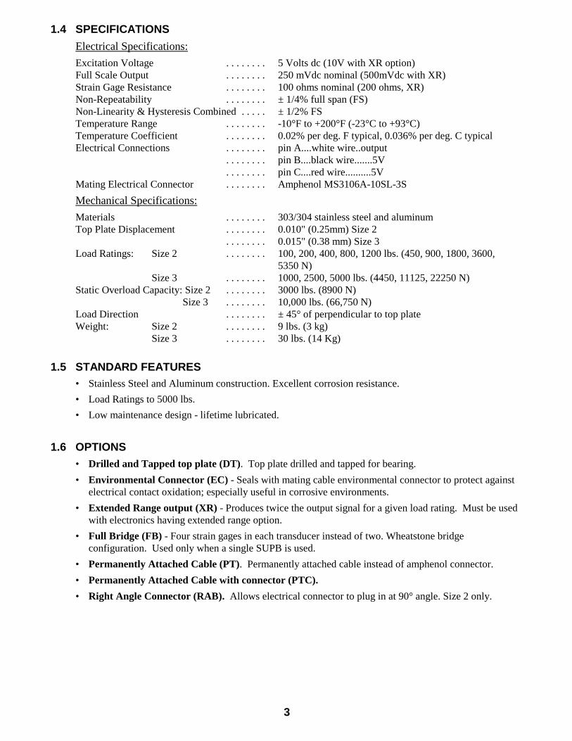
1.4 SPECIFICATIONS
Electrical Specifications:
Excitation Voltage . . . . . . . . 5 Volts dc (10V with XR option)Full Scale Output . . . . . . . . 250 mVdc nominal (500mVdc with XR)Strain Gage Resistance . . . . . . . . 100 ohms nominal (200 ohms, XR)Non-Repeatability . . . . . . . . ± 1/4% full span (FS)Non-Linearity & Hysteresis Combined . . . . . ± 1/2% FSTemperature Range . . . . . . . . -10°F to +200°F (-23°C to +93°C)Temperature Coefficient . . . . . . . . 0.02% per deg. F typical, 0.036% per deg. C typicalElectrical Connections . . . . . . . . pin A....white wire..output
. . . . . . . . pin B....black wire.......5V
. . . . . . . . pin C....red wire..........5VMating Electrical Connector . . . . . . . . Amphenol MS3106A-10SL-3S
Mechanical Specifications:
Materials . . . . . . . . 303/304 stainless steel and aluminumTop Plate Displacement . . . . . . . . 0.010" (0.25mm) Size 2
. . . . . . . . 0.015" (0.38 mm) Size 3Load Ratings: Size 2 . . . . . . . . 100, 200, 400, 800, 1200 lbs. (450, 900, 1800, 3600,
5350 N)Size 3 . . . . . . . . 1000, 2500, 5000 lbs. (4450, 11125, 22250 N)
Static Overload Capacity: Size 2 . . . . . . . . 3000 lbs. (8900 N) Size 3 . . . . . . . . 10,000 lbs. (66,750 N)
Load Direction . . . . . . . . ± 45° of perpendicular to top plateWeight: Size 2 . . . . . . . . 9 lbs. (3 kg)
Size 3 . . . . . . . . 30 lbs. (14 Kg)
1.5 STANDARD FEATURES
• Stainless Steel and Aluminum construction. Excellent corrosion resistance.
• Load Ratings to 5000 lbs.
• Low maintenance design - lifetime lubricated.
1.6 OPTIONS
• Drilled and Tapped top plate (DT). Top plate drilled and tapped for bearing.
• Environmental Connector (EC) - Seals with mating cable environmental connector to protect againstelectrical contact oxidation; especially useful in corrosive environments.
• Extended Range output (XR) - Produces twice the output signal for a given load rating. Must be usedwith electronics having extended range option.
• Full Bridge (FB) - Four strain gages in each transducer instead of two. Wheatstone bridgeconfiguration. Used only when a single SUPB is used.
• Permanently Attached Cable (PT). Permanently attached cable instead of amphenol connector.
• Permanently Attached Cable with connector (PTC).
• Right Angle Connector (RAB). Allows electrical connector to plug in at 90° angle. Size 2 only.

4
SECTION 2 INSTALLATION
2.1 DIMENSIONS
SIZE A B C D E F H K L M N O P R S
2
in. 2.62 9.00 2.88 2.62 3.80 0.45 8.00 8.00 --- 0.53 1.36 0.95 4.54 1.31 0.56
mm. 67 229 73 67 96 11 203 203 --- 14 34 24 115 33 14
3 in 4.50 13.50 5.74 4.12 --- 0.94 12.25 11.25 2.75 0.53 2.97 1.65 6.82 --- 0.94
mm. 114 343 146 105 --- 24 311 286 70 14 75 42 173 --- 24
Figure 3 - DIMENSIONS
5
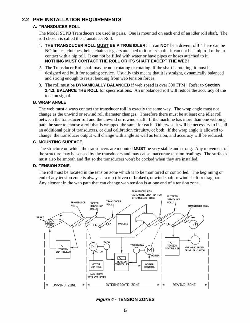
2.2 PRE-INSTALLATION REQUIREMENTSA. TRANSDUCER ROLL
The Model SUPB Transducers are used in pairs. One is mounted on each end of an idler roll shaft. Theroll chosen is called the Transducer Roll.
1. THE TRANSDUCER ROLL MUST BE A TRUE IDLER! It can NOT be a driven roll! There can beNO brakes, clutches, belts, chains or gears attached to it or its shaft. It can not be a nip roll or be incontact with a nip roll. It can not be filled with water or have pipes or hoses attached to it. NOTHING MUST CONTACT THE ROLL OR ITS SHAFT EXCEPT THE WEB!
2. The Transducer Roll shaft may be non-rotating or rotating. If the shaft is rotating, it must bedesigned and built for rotating service. Usually this means that it is straight, dynamically balancedand strong enough to resist bending from web tension forces.
3. The roll must be DYNAMICALLY BALANCED if web speed is over 300 FPM! Refer to Section2.4.3: BALANCE THE ROLL for specifications. An unbalanced roll will reduce the accuracy of thetension signal.
B. WRAP ANGLE
The web must always contact the transducer roll in exactly the same way. The wrap angle must notchange as the unwind or rewind roll diameter changes. Therefore there must be at least one idler rollbetween the transducer roll and the unwind or rewind shaft. If the machine has more than one webbingpath, be sure to choose a roll that is wrapped the same for each. Otherwise it will be necessary to installan additional pair of transducers, or dual calibration circuitry, or both. If the wrap angle is allowed tochange, the transducer output will change with angle as well as tension, and accuracy will be reduced.
C. MOUNTING SURFACE.
The structure on which the transducers are mounted MUST be very stable and strong. Any movement ofthe structure may be sensed by the transducers and may cause inaccurate tension readings. The surfacesmust also be smooth and flat so the transducers won't be cocked when they are installed.
D. TENSION ZONE.
The roll must be located in the tension zone which is to be monitored or controlled. The beginning orend of any tension zone is always at a nip (driven or braked), unwind shaft, rewind shaft or drag bar. Any element in the web path that can change web tension is at one end of a tension zone.
Figure 4 - TENSION ZONES

6
2.3 SELECTION OF LOAD RATINGA. FACTORS AFFECTING LOAD RATING SELECTION
The SUPB transducer is designed to measure forces which are mostly perpendicular to the top plate. It isavailable in eight load ratings: 100, 200, 400, 800, and 1200 for Size 2, and 1000, 2500, and 5000 lbs forSize 3. The load rating appropriate for a particular web application depends on the transducer’smounting orientation, roll weight, web tension, wrap angle, and direction of tension force.
The transducer can be mounted in any angular orientation about the roll axis. It is designed for sensing tension force with direction ‘FT’ within +\ - 45o of the line ‘V’ which is perpendicular to the transducertop plate (see Figure 6). It will function accurately outside of this +/-45° range, but the following loadrating equations are not as accurate for prediction outside of this range. Outside of this angular range,DFE’s model UPBH transducer should be used. The UPBH transducer is used to measure tension withthe applied force directed mostly parallel to the top-plate.
When looking at the SUPB transducer orientation sketches on the next page, note that the side view ofeach transducer shows one end as the pivot end (stamped ‘P’). This designation distinguishes this end ofthe transducer’s internal pivot end from the other end, which is the sensing-beam end. The pair of transducers are supporting a shaft and must have the pivot end to the same side of the shaft. Because ofits asymmetric internal design, the transducer is significantly more sensitive to non-perpendicularapplied force directed through the sensing-beam end than through the pivot end.
As a result, calculating net force and selecting a load rating are not as straightforward as with othertransducers. We strongly recommend that you ask your sales representative or one of DFE’s applicationsengineers to select a load-rating for your application.
If you wish to calculate the correct total net force for an application yourself, follow the Load RatingSelection instructions on the next page. Note that total net force is the sum of two components: net forcefrom roll weight and net force from web tension.
The correct load rating for a SUPB transducer pair can then be selected by matching your calculatedtotal net force to the range of values from the corresponding Max. Net Force list.
B. SELECTING THE LOAD RATING
To select the correct load rating for an SUPB transducer (to be used in a pair), look at Figures 5 & 6. You will need to calculate Net Force from Roll Weight and Net Force from Tension being sure tomaintain their current algebraic sign (+,-). The sum of these net force components equals the Total NetForce used to select the correct load rating.
FT = direction of force midway between two tensions
V = line ‘V’, perpendicular to mount surface and top plate
1. Enter values from your application for the equation variables below.
T = max. tension in web _____________
W = weight of roll and support bearings _____________
A = angle between weight ‘W’ direction and line V_______
B = web wrap angle (=180° - C in diagram 2) __________
D = angle between tension force direction FT and line V_____.
Dimensional Constants inches (mm)
Size 2 Size 3 L = 2.4 (61) 4.5 (114) H = 1.5 (38) + a* 3.0 (76) + a*
*a = 1.0 (25.4) to 2.5 (63.5) 1.5 (38.1) to 3.0 (76.2)*Where “ a ” is the idler roll shaft center height from the top plate surface. If the tension force FT isdirected through the pivot end of the transducer at D = 45°, then when the pillow block height is morethan the minimum height specified above, the output signal polarity will be reversed.
7
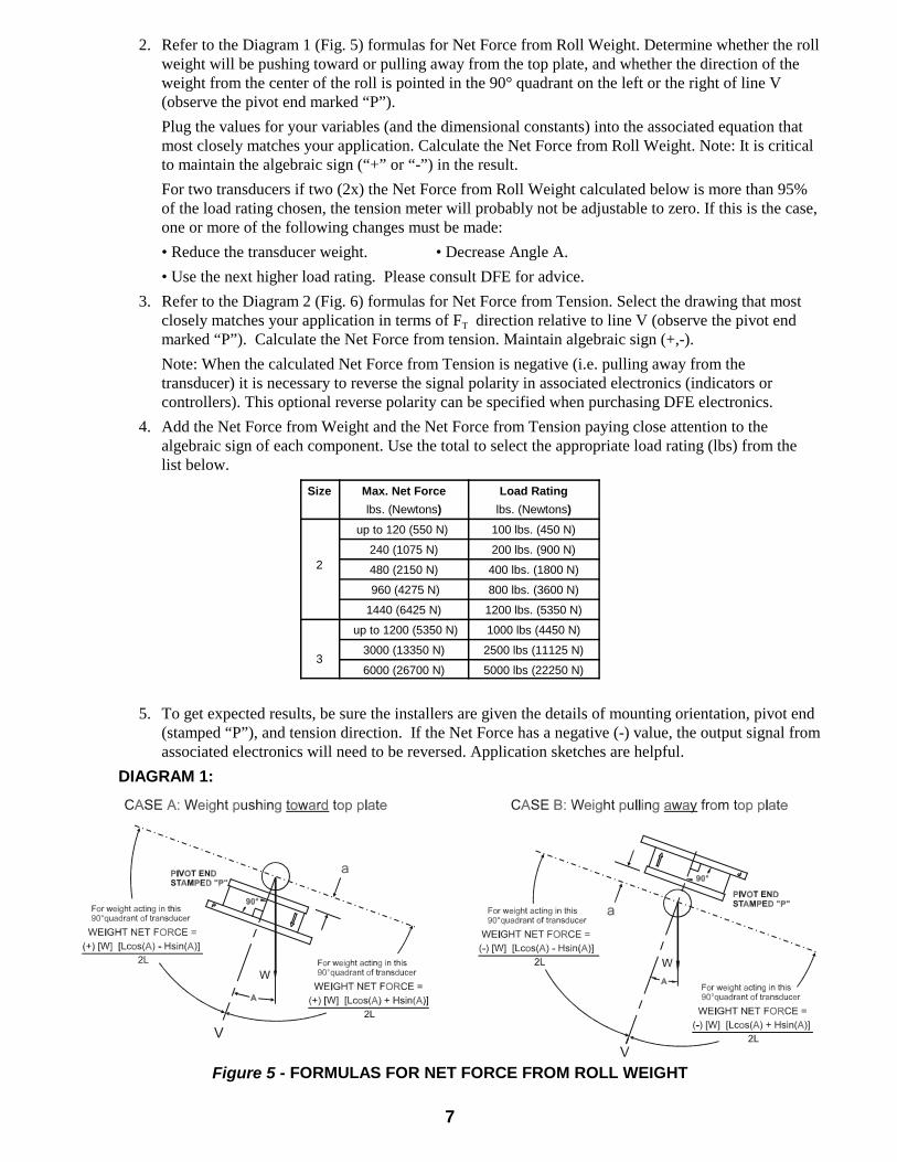
2. Refer to the Diagram 1 (Fig. 5) formulas for Net Force from Roll Weight. Determine whether the rollweight will be pushing toward or pulling away from the top plate, and whether the direction of theweight from the center of the roll is pointed in the 90° quadrant on the left or the right of line V(observe the pivot end marked “P”).
Plug the values for your variables (and the dimensional constants) into the associated equation thatmost closely matches your application. Calculate the Net Force from Roll Weight. Note: It is criticalto maintain the algebraic sign (“+” or “-”) in the result.
For two transducers if two (2x) the Net Force from Roll Weight calculated below is more than 95%of the load rating chosen, the tension meter will probably not be adjustable to zero. If this is the case,one or more of the following changes must be made:
• Reduce the transducer weight. • Decrease Angle A.
• Use the next higher load rating. Please consult DFE for advice.
3. Refer to the Diagram 2 (Fig. 6) formulas for Net Force from Tension. Select the drawing that mostclosely matches your application in terms of FT direction relative to line V (observe the pivot endmarked “P”). Calculate the Net Force from tension. Maintain algebraic sign (+,-).
Note: When the calculated Net Force from Tension is negative (i.e. pulling away from thetransducer) it is necessary to reverse the signal polarity in associated electronics (indicators orcontrollers). This optional reverse polarity can be specified when purchasing DFE electronics.
4. Add the Net Force from Weight and the Net Force from Tension paying close attention to thealgebraic sign of each component. Use the total to select the appropriate load rating (lbs) from thelist below.
Size Max. Net Force
lbs. (Newtons)
Load Rating
lbs. (Newtons)
2
up to 120 (550 N) 100 lbs. (450 N)
240 (1075 N) 200 lbs. (900 N)
480 (2150 N) 400 lbs. (1800 N)
960 (4275 N) 800 lbs. (3600 N)
1440 (6425 N) 1200 lbs. (5350 N)
3
up to 1200 (5350 N) 1000 lbs (4450 N)
3000 (13350 N) 2500 lbs (11125 N)
6000 (26700 N) 5000 lbs (22250 N)
5. To get expected results, be sure the installers are given the details of mounting orientation, pivot end(stamped “P”), and tension direction. If the Net Force has a negative (-) value, the output signal fromassociated electronics will need to be reversed. Application sketches are helpful.
DIAGRAM 1:
Figure 5 - FORMULAS FOR NET FORCE FROM ROLL WEIGHT

8
DIAGRAM 2:
NOTES:
1. If FT is perpendicular (Angle D = 0°) and toward the top plate, either of thetwo drawing/formulas on the left can be simplified to +2T sin(B/2).
If FT is perpendicular (Angle D = 0°) and pulling away from the top plate,either of the two drawing/formulas on the right can be simplified to -2Tsin(B/2).
2. These tension force equations have an oversizing factor of two (2) for tensionsurges.
Figure 6 - FORMULAS FOR NET FORCE FROM TENSION

9
2.4 INSTALLING THE TRANSDUCERS
Model SUPB Transducers are very easy to install. Normally, both transducers are mounted on the machineand the roll is then installed on them. Follow the simple steps below.
1. MOUNT THE TRANSDUCERS ON THE MACHINE
Mount the transducers on the machine making sure that the transducer force direction and mount surfaceis the same as that used when the transducer load rating was sized for this application, and that thestamped pivot ends of both transducers are on the same side of the roll. Differences may result insignificant unsatisfactory performance.
Figure 7 - EXAMPLE OF A STANDARD TRANSDUCER ORIENTATION
2. DETERMINE SHAFT LENGTH
Measure the center to center distance between the transducer bases, (call this DT ). Use the followingformula to determine the minimum shaft length.
SHAFT LENGTH = DT + width of one pillow block bearing
3. BALANCE THE ROLL
The roll must be dynamically balanced if web speed is 300 FPM or more. Balance the roll to QualityGrade G-2.5 as described in ISO 1940 and ANSI S2.19-75 standards. If these standards are notavailable, please contact DOVER FLEXO ELECTRONICS and we will provide the appropriate data.
4. SELECTION OF PILLOW BLOCK BEARING
The bearing should have self-aligning and floating capabilities. The self-aligning feature will avoidunnecessary stress on the transducers caused by misalignment during installation and by roll deflectionduring operation. The floating feature will avoid forces caused by temperature variations of the shaft.These factors could cause inaccurate output from the transducers. Normally, only one bearing needs tofloat (move axially a small amount). The other can be fixed. A 100° F temperature change causesapproximately 1/8" change in length of a 10 ft. long piece of steel.
10
5. REMOVE THE TOP PLATE TO DRILL FOR THE PILLOW BLOCK BEARING
1. Remove the eight screws holding the top plate to the transducer.
2. Remove the top plate and drill and tap the holes for the pillow block bearing being used.
3. Replace the top plate and secure with the eight screws. Tighten the screws to 6 ft.-lbs. of torque forSize 2, and 30 ft.-lbs of torque for Size 3.
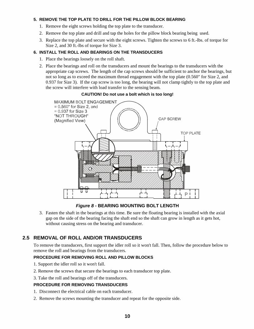
6. INSTALL THE ROLL AND BEARINGS ON THE TRANSDUCERS
1. Place the bearings loosely on the roll shaft.
2. Place the bearings and roll on the transducers and mount the bearings to the transducers with theappropriate cap screws. The length of the cap screws should be sufficient to anchor the bearings, butnot so long as to exceed the maximum thread engagement with the top plate (0.560" for Size 2, and0.937 for Size 3). If the cap screw is too long, the bearing will not clamp tightly to the top plate andthe screw will interfere with load transfer to the sensing beam.
CAUTION! Do not use a bolt which is too long!
Figure 8 - BEARING MOUNTING BOLT LENGTH
3. Fasten the shaft in the bearings at this time. Be sure the floating bearing is installed with the axialgap on the side of the bearing facing the shaft end so the shaft can grow in length as it gets hot,without causing stress on the bearing and transducer.
2.5 REMOVAL OF ROLL AND/OR TRANSDUCERS
To remove the transducers, first support the idler roll so it won't fall. Then, follow the procedure below toremove the roll and bearings from the transducers.
PROCEDURE FOR REMOVING ROLL AND PILLOW BLOCKS
1. Support the idler roll so it won't fall.
2. Remove the screws that secure the bearings to each transducer top plate.
3. Take the roll and bearings off of the transducers.
PROCEDURE FOR REMOVING TRANSDUCERS
1. Disconnect the electrical cable on each transducer.
2. Remove the screws mounting the transducer and repeat for the opposite side.
11
SECTION 3 CALIBRATION AND SETUP
3.1 INTRODUCTION
There are no calibration adjustments on the Model SUPB Transducer itself. The instructions below are forthe electronics which the transducers are connected to. All of the following terminology and procedures,assume that the transducers are connected to a DOVER FLEXO ELECTRONICS tension controller ortension indicator. If some other electronics are being used, you should follow the instructions furnishedwith them.
These are general instructions which are correct for most DFE controllers and indicators, and are placedhere for your convenience. If you have any difficulty calibrating or if there is any discrepancy betweenthese instructions and those in the Instruction Manual for the indicator or controller, you should disregardthese instructions and follow the instructions in the Manual for the indicator or controller.
The transducers must be properly installed and orientated as directed in SECTION 2.4.
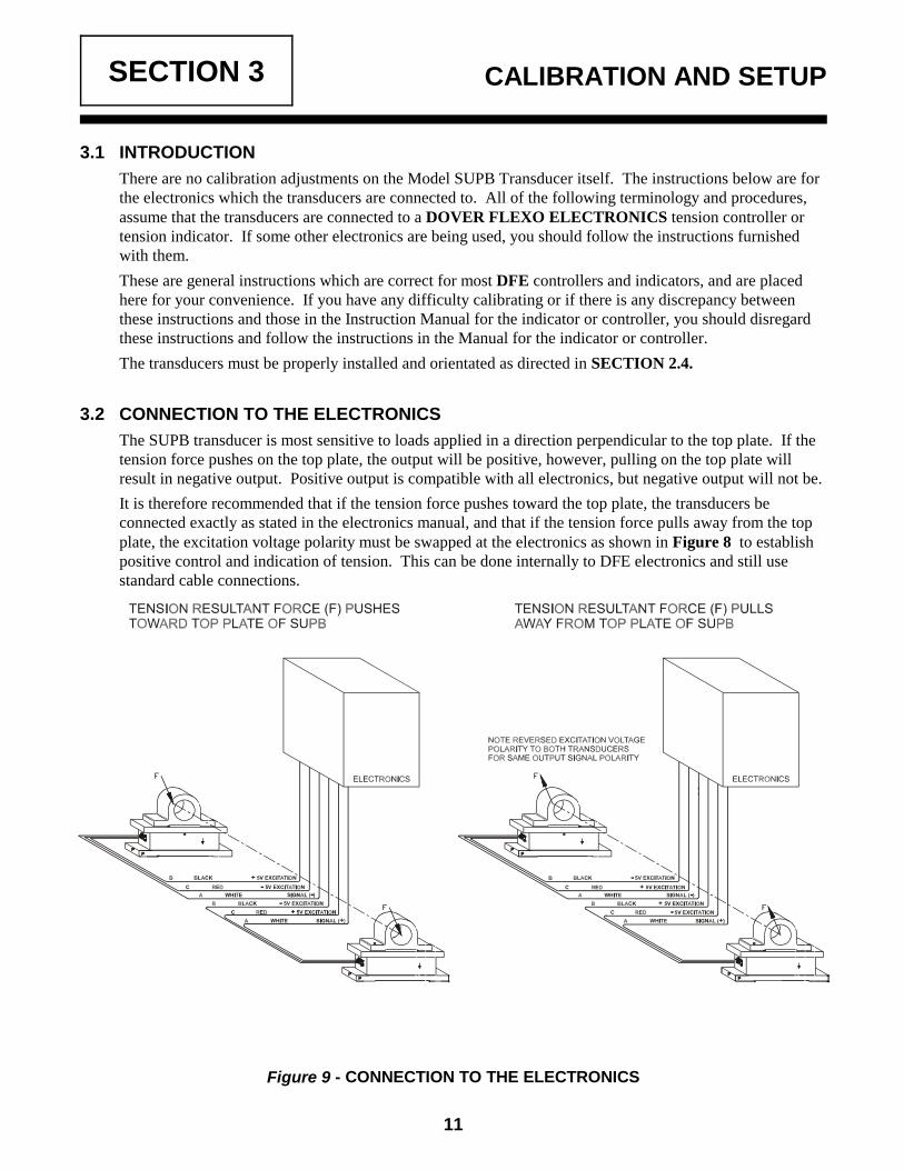
3.2 CONNECTION TO THE ELECTRONICS
The SUPB transducer is most sensitive to loads applied in a direction perpendicular to the top plate. If thetension force pushes on the top plate, the output will be positive, however, pulling on the top plate willresult in negative output. Positive output is compatible with all electronics, but negative output will not be.
It is therefore recommended that if the tension force pushes toward the top plate, the transducers beconnected exactly as stated in the electronics manual, and that if the tension force pulls away from the topplate, the excitation voltage polarity must be swapped at the electronics as shown in Figure 8 to establishpositive control and indication of tension. This can be done internally to DFE electronics and still usestandard cable connections.
Figure 9 - CONNECTION TO THE ELECTRONICS

12
3.3 ZERO THE TENSION METER
1. Turn the "POWER" switch off. If the meter does not read zero, turn the mechanical adjustment screwon the meter face so the needle indicates zero tension.
2. Find an object that weighs at least 25% of the maximum value on the tension meter scale. (Be sure youknow the exact weight).
3. Find a rope, tape, or wire that will support the weight in 2. above.
4. Verify that there is no web contacting the Transducer Roll. Turn the "POWER" switch on. Wait a fewseconds for the tension meter to settle. Turn the "CALIBRATE" pot. to approximately 75%. Then, turnthe "ZERO" pot. so the tension meter reads zero tension.
3.4 CALIBRATE THE TENSION METER
See Figure 9. Pass the rope over the Transducer Roll in exactly the same path as the web follows. Tie theend in the machine at least one idler roll beyond the Transducer Roll. Pass the other end by at least oneidler roll before the Transducer Roll. Be sure the rope does not pass over any driven rolls, braked rolls ordead bars. (This will cause inaccurate calibration). Attach the weight to the free end of the rope and let ithang without touching anything. Turn the "CALIBRATE" pot. so the tension meter reads the same as theweight. Remove the weight and rope. This concludes the calibration procedure.
Rope follows web path exactly. All rolls must be free turning idlers.
Figure 10 - WEB PATH

13
SECTION 4 CARE AND MAINTENANCE
Your Dover Flexo Model SUPB Tension Transducers have been manufactured of quality materials. Themodel SUPB bearing rod is hardened to Rockwell 60C, then ground to size with close tolerances. For thehighest beam rating, the spherical alignment bearing is oversized by more than a factor of 6 for static load. For worst case dynamic load with an unbalanced machine roll, there is and oversizing factor of more than 2. The bearing is coated with a Molybdenum Disulfide lube and contained in s sealed bearing block which ispacked with grease.
With proper application and installation your transducers will be relatively maintenance free and longlasting. Any changes in your application which affect the dynamics of your equipment such as web speed, net force, material, etc. could possibly require upgrading of load rating or roll change. Contact Dover forspecific information and engineering approval.

14
SECTION 5 TROUBLESHOOTING GUIDE
This is a list of problems which could occur during initial start-up or afterwards. The probable causes arelisted with the most likely one first and the least likely one last.
1. TRANSDUCER ROLL SHAKES, VIBRATES or BOUNCES
a. Roll is not balanced. See Section 2.4.3 and Section 2.2.A.3.
b. Shaft is not clamped tightly in bearings. Mounting screws are loose or shaft diameter is undersize.
c. Transducer mounting bolts are not tight.
d. Shaft is too weak or there is too much shaft extension between the ends roll and the transducers.
e. Shaft is bent or too weak. (This refers to live shaft idler rolls, only)
f. Roll is turning at its natural frequency. Call DFE for analysis of conditions and solution to problem.
2. CAN NOT ADJUST TENSION METER TO READ ZERO WHEN WEB IS SLACK
a. Transducer roll is too heavy. See Section 2.3.B.2.
b. Transducers are pre-loaded. See Sections 2.4.2 and 2.4.4.
3. TENSION METER READS BACKWARDS
a. Transducers are installed backwards with force arrow pointing in opposite direction. See Section2.4.1.
b. Transducer cables are connected wrong at controller/indicator terminal strip. Signal wires arereversed.
4. TENSION METER NEEDLE PEGS HIGH OR LOW
a. Meter is not electrically adjusted to zero. See Section 3.3.
b. Transducers are pre-loaded. See Sections 2.4.2 and 2.4.4.
c. Transducer cable has broken wire, poor connection or short circuit.
d. A strain gage has failed. To verify: Unplug the transducer cable and use an ohm-meter to measurethe resistance of the gages at the connector on the transducer. Measure between pins A,B, and A,C. In each case, the resistance should be about 100 ohms. Measure the resistance between any pin andthe outside of the transducer. The meter should read infinite resistance. Apply a force to the roll byhand or by using a rope and a weight, in the direction of the tension force and maintain it while againmeasuring between pins A,B and A,C. The resistance should be only a few ohms different frombefore.
e. Failure in the tension amplifier circuit of the controller/indicator.
5. TENSION METER DOES NOT READ ZERO WHEN WEB IS SLACK AND READING DRIFTS WITHTIME.
a. Meter is not calibrated. See Section 3.4.
b. Transducers are pre-loaded. See Sections 2.4.2 and 2.4.4.
c. The structure the transducers are mounted on is weak. See Section 2.2.C.
d. Transducer cable has a broken wire, poor connection or short circuit.
e. A strain gage is cracked. Perform the test in 4d above.
15
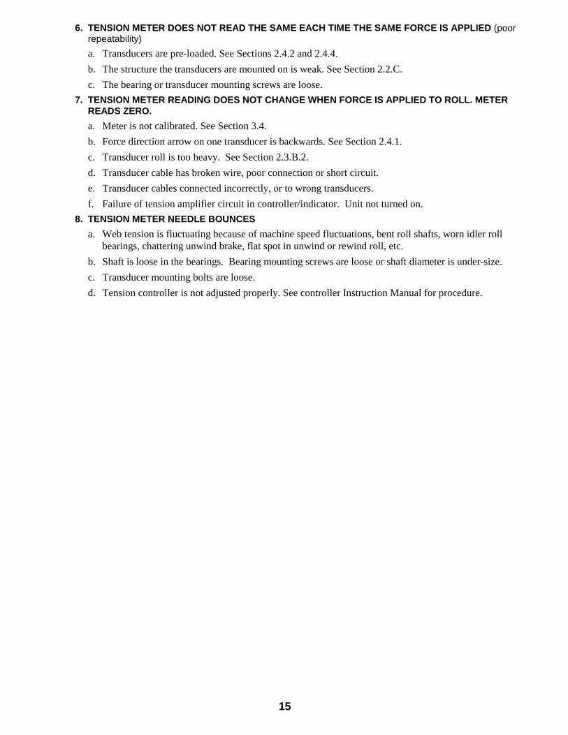
6. TENSION METER DOES NOT READ THE SAME EACH TIME THE SAME FORCE IS APPLIED (poorrepeatability)
a. Transducers are pre-loaded. See Sections 2.4.2 and 2.4.4.
b. The structure the transducers are mounted on is weak. See Section 2.2.C.
c. The bearing or transducer mounting screws are loose.
7. TENSION METER READING DOES NOT CHANGE WHEN FORCE IS APPLIED TO ROLL. METERREADS ZERO.
a. Meter is not calibrated. See Section 3.4.
b. Force direction arrow on one transducer is backwards. See Section 2.4.1.
c. Transducer roll is too heavy. See Section 2.3.B.2.
d. Transducer cable has broken wire, poor connection or short circuit.
e. Transducer cables connected incorrectly, or to wrong transducers.
f. Failure of tension amplifier circuit in controller/indicator. Unit not turned on.
8. TENSION METER NEEDLE BOUNCES
a. Web tension is fluctuating because of machine speed fluctuations, bent roll shafts, worn idler rollbearings, chattering unwind brake, flat spot in unwind or rewind roll, etc.
b. Shaft is loose in the bearings. Bearing mounting screws are loose or shaft diameter is under-size.
c. Transducer mounting bolts are loose.
d. Tension controller is not adjusted properly. See controller Instruction Manual for procedure.

16
SECTION 6 REPLACEMENT PARTS
6.1 REPLACEMENT PARTS FOR THE SUPB TRANSDUCERS
TOP PLATE:
Size 2: 203-1843
Size 3: 203-1584
CONNECTORS:
Sizes 2 & 3: MS3102A-10SL
CABLES: 15 FT. 20 FT. 25 FT. 30 FT.
C - C: 721-1554 721-1539 721-1540 721-1541
w/ Rt. Angle Conn 721-0083
C - N: 721-1555 721-1542 721-1542 721-1544
w/Rt. Angle Conn 721-1555
INSTRUCTION MANUAL: DOC 801-0906

17
Appendix A: Transducer Electrical Connections
Figure 11 - MODEL UPB TRANSDUCER WIRING
18
Appendix B: Typical Tensions for Various Materials
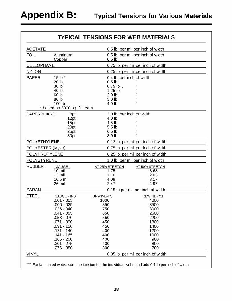
TYPICAL TENSIONS FOR WEB MATERIALS
ACETATE 0.5 lb. per mil per inch of width
FOIL Aluminum 0.5 lb. per mil per inch of widthCopper 0.5 lb. "
CELLOPHANE 0.75 lb. per mil per inch of width
NYLON 0.25 lb. per mil per inch of width
PAPER 15 lb * 0.4 lb. per inch of width20 lb 0.5 lb. " 30 lb 0.75 lb . "40 lb 1.25 lb. "60 lb 2.0 lb. "80 lb 3.0 lb. "100 lb 4.0 lb. "
* based on 3000 sq. ft. ream
PAPERBOARD 8pt 3.0 lb. per inch of width12pt 4.0 lb. "15pt 4.5 lb. "20pt 5.5 lb. "25pt 6.5 lb. "30pt 8.0 lb. "
POLYETHYLENE 0.12 lb. per mil per inch of width
POLYESTER (Mylar) 0.75 lb. per mil per inch of width
POLYPROPYLENE 0.25 lb. per mil per inch of width
POLYSTYRENE 1.0 lb. per mil per inch of width
RUBBER GAUGE AT 25% STRETCH AT 50% STRETCH10 mil 1.75 3.6812 mil 1.10 2.0316.5 mil 4.09 8.1726 mil 2.47 4.97
SARAN 0.15 lb per mil per inch of width
STEEL GAUGE - INS UNWIND-PSI REWIND-PSI.001 -.005 1000 4000.006 -.025 850 3500.026 -.040 750 3000.041 -.055 650 2600.058 -.070 550 2200.071 -.090 450 1800.091 -.120 450 1400.121 -.140 400 1200.141 -.165 400 1000.166 -.200 400 900.201 -.275 400 800.276 -.380 300 700
VINYL 0.05 lb. per mil per inch of width
*** For laminated webs, sum the tension for the individual webs and add 0.1 lb per inch of width.

19
TERMS AND CONDITIONS OF SALE AND SHIPMENT
1. THE COMPANY 5/1/00Dover Flexo Electronics, Inc. is hereinafter referred to as the Company.
2. CONFLICTING OR MODIFYING TERMS No modification of, additions to or conflicting provisions to theseterms and conditions of sale and shipment, whether oral orwritten, incorporated into Buyer's order or other communicationsare binding upon the Company unless specifically agreed to bythe Company in writing and signed by an officer of the Company.Failure of the Company to object to such additions, conflicts ormodifications shall not be construed as a waiver of these termsand conditions nor an acceptance of any such provisions.
3. GOVERNING LAWThis contract shall be governed by and construed according to thelaws of the state of New Hampshire, U.S.A. The parties agree thatany and all legal proceedings pursuant to this contract shall takeplace under the jurisdiction of the courts of the State of NewHampshire in the judicial district of Strafford County.
4. PENALTY CLAUSESPenalty clauses of any kind contained in orders, agreements orany other type of communication are not binding on the Companyunless agreed to by an officer of the Company in writing.
5. WARRANTYDover Flexo Electronics, Inc. warrants its' products to be free ofdefects in material and workmanship for five years from date oforiginal shipment. Warranty is valid on products purchased on orafter April 2, 1999. During the warranty period the Company willrepair or replace defective products free of charge if suchproducts are returned with all shipping charges prepaid and if,upon examination, the product is shown to be defective. Thiswarranty shall not apply to products damaged by abuse, neglect,accident, modification, alteration or mis-use. Normal wear is notwarranteed. All repairs and replacements under the provisions ofthis warranty shall be made at Dover Flexo Electronics or at anauthorized repair facility. The Company shall not be liable forexpenses incurred to repair or replace defective products at anyother location or by unauthorized persons or agents. This warrantycontains all of the obligations and warranties of the Company.There are no other warranties, either expressed or implied. Nowarranty is given regarding merchantability or suitability for anyparticular purpose. The Company shall not be liable in eitherequity or law for consequential damages, losses or expensesincurred by use of or inability to use its' products or for claimsarising from same. No warranty is given for products of othermanufacturers even though the Company may provide theseproducts with its' own or by themselves. The provisions of thiswarranty can not be changed in any way by any agent oremployee of the Company. Notice of defects must be receivedwithin the warranty period or the warranty is void.
6. PAYMENTSStandard terms of credit are net 30 days from date of shipment,providing satisfactory credit is established with the Company.Amounts past due are subject to a service charge of 1.5% permonth or portion thereof or 18% per annum. The Companyreserves the right to submit any unpaid late invoices to a thirdparty for collection and Buyer shall pay all reasonable costs ofsuch collection in addition to the invoice amount. All quoted pricesand payments shall be in U.S. Dollars.If the Company judges that the financial condition or paymentpractices of the Buyer does not justify shipment under thestandard terms or the terms originally specified, the Company mayrequire full or partial payment in advance or upon delivery. TheCompany reserves the right to make collection on any termsapproved in writing by the Company's Finance Department. Eachshipment shall be considered a separate and independenttransaction and payment therefore shall be made accordingly. If
the work covered by the purchase order is delayed by the Buyer,upon demand by Company payments shall be made on thepurchase price based upon percentage of completion.
7. TAXESAny tax, duty, custom, fee or any other charge of any naturewhatsoever imposed by any governmental authority on ormeasured by any transaction between the Company and theBuyer shall be paid by the Buyer in addition to the prices quoted orinvoiced.
8. RETURNSWritten authorization must be obtained from the Company'sfactory before returning any material for which the Buyer expectscredit, exchange, or repairs under the Warranty. Returnedmaterial (except exchanges or repairs under the Warranty) shallbe subject to a minimum re-stocking charge of 15%. Non-standardmaterial or other material provided specially to the Buyer'sspecification shall not be returnable for any reason. All material re-turned, for whatever reason, shall be sent with all freight chargesprepaid by the Buyer.
9. SHIPPING METHOD AND CHARGESAll prices quoted are F.O.B. the Company's factory. The Companyshall select the freight carrier, method and routing. Shippingcharges are prepaid and added to the invoice of Buyers withapproved credit, however the Company reserves the right to shipfreight-collect if it prefers. Shipping charges will include a chargefor packaging. Company will pay standard ground freight chargesfor items being returned to Buyer which are repaired or replacedunder the Warranty.
10. CANCELLATION, CHANGES, RESCHEDULINGBuyer shall reimburse Company for costs incurred for any item onorder with the Company which is canceled by the Buyer. Costsshall be determined by common and accepted accounting prac-tices. A one-time hold on any item ordered from the Company shall beallowed for a maximum of 30 days. After 30 days, or upon noticeof a second hold, Company shall have the right to cancel theorder and issue the appropriate cancellation charges which shallbe paid by Buyer. Items held for the Buyer shall be at the risk andexpense of the Buyer unless otherwise agreed upon in writing.Company reserves the right to dispose of canceled material as itsees fit without any obligation to Buyer.If Buyer makes, or causes to make, any change to an order theCompany reserves the right to change the price accordingly.
11. PRICESPrices published in price lists, catalogs or elsewhere are subjectto change without notice and without obligation. Written quotedprices are valid for thirty days only.
12. EXPORT SHIPMENTSPayment for shipments to countries other than the U.S.A. andCanada or to authorized distributors shall be secured by cash inadvance or an irrevocable credit instrument approved by an officerof the Company. An additional charge of 10% will apply to anyletter of credit. There will be an extra charge for packaging anddocumentation.
13. CONDITION OF EQUIPMENTBuyer shall keep products in good repair and shall be responsiblefor same until the full purchase price has been paid.
14. OWNERSHIPProducts sold are to remain the property of the Company until fullpayment of the purchase price is made.

20
DECLARATION OF CONFORMITY
We,
Dover Flexo Electronics
217 Pickering Road
Rochester, NH 03867 USA
Tel: (603) 332-6150
Fax: (603) 332-3758
declare under our sole responsibility that the product:
Model SUPB Web Tension Transducer,
manufactured after the date 1 May 1997, and to which this declaration relates, is in conformity with the followingstandards or other normative documents:
EN 55011: Radiated and Conducted Emissions
EN 50082-2: Electromagnetic compatibility - Generic immunity standard,
Part 2. Industrial Environment, to include:
ENV 50140: Radio Frequency Immunity - AM
ENV 50141: Conducted Radio Frequency Interference
ENV 50204: Radio Frequency Immunity - Pulse Modulated
ENV 61000-4-2: Electrostatic Discharge
EN 61000-4-4: Electrical Fast Transient Bursts
following the provisions of Council Directive 89/336/EEC of 3 May 1989 on the approximation of the laws of themember states relating to electromagnetic compatibility (the "EMC Directive").
The Technical Construction File is maintained at:
Dover Flexo Electronics
217 Pickering Road
Rochester, NH 03867 USA
Per Annex II R of the Machinery Directive (89/392/EEC):
The machinery, product, assembly, or sub-assembly covered by this Declaration of Conformity mustnot be put into service until the machinery into which it is to be incorporated has been declared in conformitywith the provisions of the applicable Directive(s).
Date of issue: 5 May, 1997
Place of issue: Rochester, NH USA
Signed:_____________________________________________
Alan H. Wysocki, Engineering Manager8010717a.doc

21
NOTES

22
NOTES
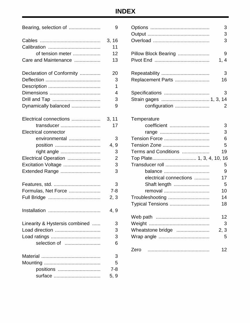
INDEX
Bearing, selection of ....................... 9
Cables ............................................ 3, 16Calibration ...................................... 11
of tension meter .................... 12Care and Maintenance ................... 13
Declaration of Conformity ............... 20Deflection ........................................ 3Description ...................................... 1Dimensions ..................................... 4Drill and Tap ................................... 3Dynamically balanced ..................... 9
Electrical connections ..................... 3, 11transducer ............................. 17
Electrical connector environmental ....................... 3position ................................. 4, 9right angle ............................. 3
Electrical Operation ........................ 2Excitation Voltage ........................... 3Extended Range ............................. 3
Features, std. .................................. 3Formulas, Net Force ....................... 7-8Full Bridge ...................................... 2, 3
Installation ...................................... 4, 9
Linearity & Hystersis combined ...... 3Load direction ................................. 3Load ratings .................................... 3
selection of .......................... 6
Material ........................................... 3Mounting ......................................... 5
positions ............................... 7-8surface .................................. 5, 9
Options ........................................... 3Output ............................................. 3Overload ......................................... 3
Pillow Block Bearing ....................... 9Pivot End ........................................ 1, 4
Repeatability ................................... 3Replacement Parts ......................... 16
Specifications ................................. 3Strain gages ................................... 1, 3, 14
configuration ......................... 2
Temperature coefficient ............................. 3range .................................... 3
Tension Force ................................. 6Tension Zone .................................. 5Terms and Conditions .................... 19Top Plate................................ 1, 3, 4, 10, 16Transducer roll ................................ 5
balance ................................. 9electrical connections ........... 17Shaft length .......................... 5removal ................................. 10
Troubleshooting .............................. 14Typical Tensions ............................. 18
Web path ....................................... 12Weight ............................................ 3Wheatstone bridge ........................ 2, 3Wrap angle ..................................... 5
Zero ............................................. 12

217 PICKERING ROADROCHESTER, NEW HAMPSHIRE 03867-4630 U.S.A
TEL: 603-332-6150FAX: 603-332-3758
E-mail: [email protected] Internet: www.dfe.com
CANADA
MEXICO
UNITED KINGDOM
EUROPE
TAIWAN
KOREA
AUSTRALIA
COLOMBIA
INDIA
CHILE
©2001 DOVER FLEXO ELECTRONICS, INC. DOC 801-0906ALL RIGHTS RESERVED F & C 0801 PRINTED IN USA