Model # SC-UN INS # Universal Source Controller...Universal Source Controller The hinged cover must...
17
Installation Instructions Model # SC-UN Universal Source Controller
Transcript of Model # SC-UN INS # Universal Source Controller...Universal Source Controller The hinged cover must...
INS #Installation Instructions Model # SC-UN
Universal Source Controller
2
Contents
Universal Source Controller
Contents
Description Page
Introduction . . . . . . . . . . . . . . . . . . . . . . . . . . . . . . . . . . . . . . . . . . . . . . . . . . . . . . . . . . . . . . . . . . . 3Welcome . . . . . . . . . . . . . . . . . . . . . . . . . . . . . . . . . . . . . . . . . . . . . . . . . . . . . . . . . . . . . . . . . . . 3Range Overview . . . . . . . . . . . . . . . . . . . . . . . . . . . . . . . . . . . . . . . . . . . . . . . . . . . . . . . . . . . . . . 3
Cabinet Dimensions . . . . . . . . . . . . . . . . . . . . . . . . . . . . . . . . . . . . . . . . . . . . . . . . . . . . . . . . . 3Specifications . . . . . . . . . . . . . . . . . . . . . . . . . . . . . . . . . . . . . . . . . . . . . . . . . . . . . . . . . . . . . . . . 5
Safety . . . . . . . . . . . . . . . . . . . . . . . . . . . . . . . . . . . . . . . . . . . . . . . . . . . . . . . . . . . . . . . . . . . . . . . 5Please Read this First. . . . . . . . . . . . . . . . . . . . . . . . . . . . . . . . . . . . . . . . . . . . . . . . . . . . . . . . . . 5Important Points for Consideration . . . . . . . . . . . . . . . . . . . . . . . . . . . . . . . . . . . . . . . . . . . . . . . 5
Ambient Atmosphere Requirements . . . . . . . . . . . . . . . . . . . . . . . . . . . . . . . . . . . . . . . . . . . . 6Mounting . . . . . . . . . . . . . . . . . . . . . . . . . . . . . . . . . . . . . . . . . . . . . . . . . . . . . . . . . . . . . . . . . . . . . 6
Location and Spacing . . . . . . . . . . . . . . . . . . . . . . . . . . . . . . . . . . . . . . . . . . . . . . . . . . . . . . . . . . 6Mounting Holes . . . . . . . . . . . . . . . . . . . . . . . . . . . . . . . . . . . . . . . . . . . . . . . . . . . . . . . . . . . . . . 7
Standard Weights . . . . . . . . . . . . . . . . . . . . . . . . . . . . . . . . . . . . . . . . . . . . . . . . . . . . . . . . . . . 7Accessing the Mounting Holes . . . . . . . . . . . . . . . . . . . . . . . . . . . . . . . . . . . . . . . . . . . . . . . . . 8
Supply Wiring . . . . . . . . . . . . . . . . . . . . . . . . . . . . . . . . . . . . . . . . . . . . . . . . . . . . . . . . . . . . . . . . . 8Wiring Flow . . . . . . . . . . . . . . . . . . . . . . . . . . . . . . . . . . . . . . . . . . . . . . . . . . . . . . . . . . . . . . . . . 8Single Phase Supply . . . . . . . . . . . . . . . . . . . . . . . . . . . . . . . . . . . . . . . . . . . . . . . . . . . . . . . . . . . 9
Connecting the Supply . . . . . . . . . . . . . . . . . . . . . . . . . . . . . . . . . . . . . . . . . . . . . . . . . . . . . . . 9Max. Wire Gauge for Input Lugs (1 Phase) . . . . . . . . . . . . . . . . . . . . . . . . . . . . . . . . . . . . . . . 9
Three Phase Supply . . . . . . . . . . . . . . . . . . . . . . . . . . . . . . . . . . . . . . . . . . . . . . . . . . . . . . . . . . . 9Connecting the Supply . . . . . . . . . . . . . . . . . . . . . . . . . . . . . . . . . . . . . . . . . . . . . . . . . . . . . . . 9Max. Wire Gauge for Input Lugs (3 Phase) . . . . . . . . . . . . . . . . . . . . . . . . . . . . . . . . . . . . . . . 9Phase Distribution to Circuits . . . . . . . . . . . . . . . . . . . . . . . . . . . . . . . . . . . . . . . . . . . . . . . . . 10Supply to Internal Circuitry . . . . . . . . . . . . . . . . . . . . . . . . . . . . . . . . . . . . . . . . . . . . . . . . . . . 10
Load Wiring . . . . . . . . . . . . . . . . . . . . . . . . . . . . . . . . . . . . . . . . . . . . . . . . . . . . . . . . . . . . . . . . . . 10High Voltage Load Wiring . . . . . . . . . . . . . . . . . . . . . . . . . . . . . . . . . . . . . . . . . . . . . . . . . . . . . . 10
Total Load Per Channel . . . . . . . . . . . . . . . . . . . . . . . . . . . . . . . . . . . . . . . . . . . . . . . . . . . . . . 11Load Wire Gauges . . . . . . . . . . . . . . . . . . . . . . . . . . . . . . . . . . . . . . . . . . . . . . . . . . . . . . . . . 11Earth Connections . . . . . . . . . . . . . . . . . . . . . . . . . . . . . . . . . . . . . . . . . . . . . . . . . . . . . . . . . . 11
High Voltage Load Wiring Flows . . . . . . . . . . . . . . . . . . . . . . . . . . . . . . . . . . . . . . . . . . . . . . . . . 11Typical Load Connections . . . . . . . . . . . . . . . . . . . . . . . . . . . . . . . . . . . . . . . . . . . . . . . . . . . . 11
Low Voltage Load Wiring . . . . . . . . . . . . . . . . . . . . . . . . . . . . . . . . . . . . . . . . . . . . . . . . . . . . . . 12Low Voltage Load Wiring Flows . . . . . . . . . . . . . . . . . . . . . . . . . . . . . . . . . . . . . . . . . . . . . . . 12Indicators . . . . . . . . . . . . . . . . . . . . . . . . . . . . . . . . . . . . . . . . . . . . . . . . . . . . . . . . . . . . . . . . . 12
Control Wiring . . . . . . . . . . . . . . . . . . . . . . . . . . . . . . . . . . . . . . . . . . . . . . . . . . . . . . . . . . . . . . . . 13Multiple Control Protocols . . . . . . . . . . . . . . . . . . . . . . . . . . . . . . . . . . . . . . . . . . . . . . . . . . . . . 13
Termination . . . . . . . . . . . . . . . . . . . . . . . . . . . . . . . . . . . . . . . . . . . . . . . . . . . . . . . . . . . . . . . 13Control Panel Operation . . . . . . . . . . . . . . . . . . . . . . . . . . . . . . . . . . . . . . . . . . . . . . . . . . . . . . . . 14
Using The Control Panel . . . . . . . . . . . . . . . . . . . . . . . . . . . . . . . . . . . . . . . . . . . . . . . . . . . . . . . 14Accessing the Operation Menu . . . . . . . . . . . . . . . . . . . . . . . . . . . . . . . . . . . . . . . . . . . . . . . 15Menu Navigation . . . . . . . . . . . . . . . . . . . . . . . . . . . . . . . . . . . . . . . . . . . . . . . . . . . . . . . . . . . 15Overriding Channels . . . . . . . . . . . . . . . . . . . . . . . . . . . . . . . . . . . . . . . . . . . . . . . . . . . . . . . . 15Setting the Time and Date . . . . . . . . . . . . . . . . . . . . . . . . . . . . . . . . . . . . . . . . . . . . . . . . . . . 15Viewing Power Data Readings . . . . . . . . . . . . . . . . . . . . . . . . . . . . . . . . . . . . . . . . . . . . . . . . 16Setting Communications Options . . . . . . . . . . . . . . . . . . . . . . . . . . . . . . . . . . . . . . . . . . . . . . 16Changing the Operation Menu Password . . . . . . . . . . . . . . . . . . . . . . . . . . . . . . . . . . . . . . . . 16
3
Introduction
Universal Source Controller
Introduction
WelcomeThe iLumin Universal Source Controller range from Eaton’s Cooper Controls Business has been designed to provide maximum flexibility in both installation and operation. Every model in the range can accept a variety of industry standard control options, from iCANbus to DMX, from ethernet to RS-485. Similarly, every model can drive a wide range of lighting loads, from incandescents to dimmable fluorescents, from non-dim apparatus to DALI digital modules.
Much care and attention has been applied to the installation and maintenance of the Universal Source Controllers. Each model provides clear, logical cable routing and every high voltage channel is controlled by an individual, easy to replace circuit.
Range OverviewEach model is specified using a part number in the following format:
Model Number Supply Voltage
Supply Type Circuits Feed Maximum
Load
SC120-06-UN-1P-ML-20
120 VAC
1 Phase6
Main Lugs 16A per Channel
SC120-12-UN-1P-ML-20 12
SC120-06-UN-3P-ML-20
3 Phase
6
SC120-12-UN-3P-ML-20 12
SC120-24-UN-3P-ML-20 24
SC277-06-UN-1P-ML-20
277 VAC
1 Phase 6
SC277-06-UN-3P-ML-20
3 Phase
6
SC277-12-UN-3P-ML-20 12
SC277-24-UN-3P-ML-20 24
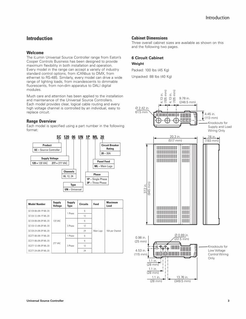
Cabinet DimensionsThree overall cabinet sizes are available as shown on this and the following two pages.
6 Circuit CabinetWeight
Packed: 100 lbs (45 Kg)
Unpacked: 88 lbs (40 Kg)
4.13
in.
(105
mm
)
37.2
in.
(945
mm
)
4.13
in.
(105
mm
)
9.78 in. (248.5 mm)
4.45 in. (113 mm)
7.6 in. (193 mm)
20.3 in. (517 mm)
Ø 0.89 in. (22.5 mm)0.98 in.
(25 mm)
4.53 in. (115 mm)
1.1 in. (28 mm)
1.1 in. (28 mm)
1.1 in. (28 mm)
13.76 in. (349.5 mm)
Knockouts for Supply and Load Wiring Only
Knockouts for Low Voltage Control Wiring Only
Ø 2.42 in.61.5 mm
SC 120 06 UN 1P ML 20
Product
SC = Source Controller
Supply Voltage
120 = 120 VAC 277 = 277 VAC
Type
UN = Universal
Circuit Breaker Rating
20 = 20A
Channels
06, 12, 24Phase
1P = Single Phase3P = Three Phase
Panel Feed
ML = Main Lugs

4
Introduction
Universal Source Controller
12 Circuit CabinetWeight
Packed: 160 lbs (72 Kg)
Unpacked: 132 lbs (60 Kg)
24 Circuit CabinetWeight
Packed (24): 220 lbs (100 Kg)
Unpacked (24): 200 lbs (90 Kg)
4.13
in.
(105
mm
)
4.13
in.
(105
mm
)
56.7
in.
(144
0 m
m)
56.7
in.
(144
0 m
m)
4.13
in.
(105
mm
)
4.13
in.
(105
mm
)
9.78 in. (248.5 mm) 9.78 in.
(248.5 mm)
4.45 in. (113 mm) 4.45 in. (113 mm)
7.6 in. (193 mm)
7.6 in. (193 mm)
20.3 in. (517 mm)
27.8 in. (707 mm)
Ø 0.89 in. (22.5 mm)
Ø 0.89 in. (22.5 mm)
0.98 in. (25 mm)
0.98 in. (25 mm)
4.53 in. (115 mm)
4.53 in. (115 mm)
1.1 in. (28 mm)
1.1 in. (28 mm)
1.1 in. (28 mm)
1.1 in. (28 mm)
1.1 in. (28 mm)
1.1 in. (28 mm)
13.76 in. (349.5 mm)
13.76 in. (349.5 mm)
Knockouts for Supply and Load Wiring Only
Knockouts for Supply and Load Wiring Only
Knockouts for Low Voltage Control Wiring Only
Knockouts for Low Voltage Control Wiring Only
Ø 2.42 in. Ø 2.42 in.61.5 mm 61.5 mm
5
Safety
Universal Source Controller
SpecificationsThe numerous models within the Universal Source Controller range share the following key specifications. Information specific to each cabinet model are provided elsewhere throughout this guide.
●● All channels provide switched (non-dim) and dimmed high voltage load control as standard
●● Leading-edge triac dimmer engines capable of withstanding repetitive inrush currents of 50 times operating current without impacting lifetime
●● All dimming and switching circuitry for every channel located on individual boards for quick and easy swap out, if necessary
●● Voltage and frequency compensation to maintain light level during supply fluctuations
●● All channels protected by thermal magnetic circuit breakers
●● Power monitoring for each circuit, phase and the total panel
●● Bypass jumpering fitted as standard to protect circuits and allow work lighting during installation
●● Selectable low voltage load control available per channel for dimmable ballast control
●● Low maintenance and quiet operation thanks to fanless, convection cooled operation
●● Support for multiple control protocols: iCAN for links to multiple control sources; DMX512A for links with entertainment systems; RS-485 for integration with building management schemes and ethernet for connection to a variety of systems
●● Dual volt-free switch inputs, with programmable responses, for integration with emergency control devices, building management systems, etc
●● Compact wall mounted design with easy access to all internal items and lockable front panel door for added security
●● Intuitive control panel provides straightforward programming and configuration of the system. The control panel allows a base level installation to be configured without the use of separate PC programming
Safety
Please Read This FirstThe Universal Source Controllers are designed, built and tested to strict safety regulations. By following the steps listed below and elsewhere within this guide, you can ensure safe installation and operation of these controller units.
●● The Universal Source Controllers must be installed only by a qualified electrician
●● The installation must comply with the appropriate electrical codes and regulations in force in your area
●● The Universal Source Controllers are designed for indoor installation and use only. The units can, however, be used to control appropriately certified exterior lighting fixtures
●● Ensure that all wiring used conforms fully to local specifications and is sufficiently rated for the installation
●● All new wiring must be fully verified before applying power
●● The high voltage supply should be fed to the Universal Source Controller via an external isolation breaker with sufficient capacity for the planned installation
●● All Universal Source Controllers exceed the weight limit for one person lifting - always use at least two people when lifting and mounting the units
●● Do not mix load types within a single channel (e.g. 120V tungsten and low voltage ballast control)
●● Ensure that the supply is fully isolated at an external breaker before removing the chassis covers. Test that power has been removed before starting to handle conductors
●● Ensure that high voltage and low voltage wiring remains separate
Important Points For Consideration●● The Universal Source Controllers must be mounted flush
with the wall, do not recess the controller chassis
●● Upper and lower raceways must not be located within 8 inches (200 mm) of the upper and lower panels of the Universal Source Controller. Use suitable conduits and couplers to link the raceways to the controller chassis
●● Allow adequate space for future maintenance of the unit. Do not install in a location that will later be difficult to access
●● The Universal Source Controllers are designed to be mounted vertically
●● During operation, the Universal Source Controllers will produce audible noise caused by electrical noise suppression circuitry and also the circuit relays within the unit. The noise is a low level buzz that varies with the level of dimming and also clicks when relays are energised. Take these matters into consideration when deciding on a suitable mounting position.
6
Safety
Universal Source Controller
●● The hinged cover must be unscrewed and removed from the front cover when the Universal Source Controller operates at full load in a high ambient environment
Ambient Atmosphere RequirementsTemperature 320 F to 1040 F (00 C to +400 C)
Humidity 0 to 95% non-condensing
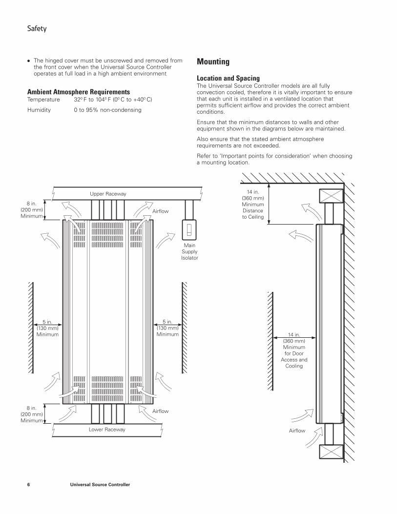
Mounting
Location and SpacingThe Universal Source Controller models are all fully convection cooled, therefore it is vitally important to ensure that each unit is installed in a ventilated location that permits sufficient airflow and provides the correct ambient conditions.
Ensure that the minimum distances to walls and other equipment shown in the diagrams below are maintained.
Also ensure that the stated ambient atmosphere requirements are not exceeded.
Refer to ‘Important points for consideration’ when choosing a mounting location.
Upper Raceway
Lower Raceway
Airflow
Airflow
Airflow
Main Supply Isolator
8 in. (200 mm) Minimum
8 in. (200 mm) Minimum
5 in. (130 mm) Minimum
14 in. (360 mm) Minimum Distance to Ceiling
14 in. (360 mm) Minimum for Door
Access and Cooling
5 in. (130 mm) Minimum
7
Mounting
Universal Source Controller
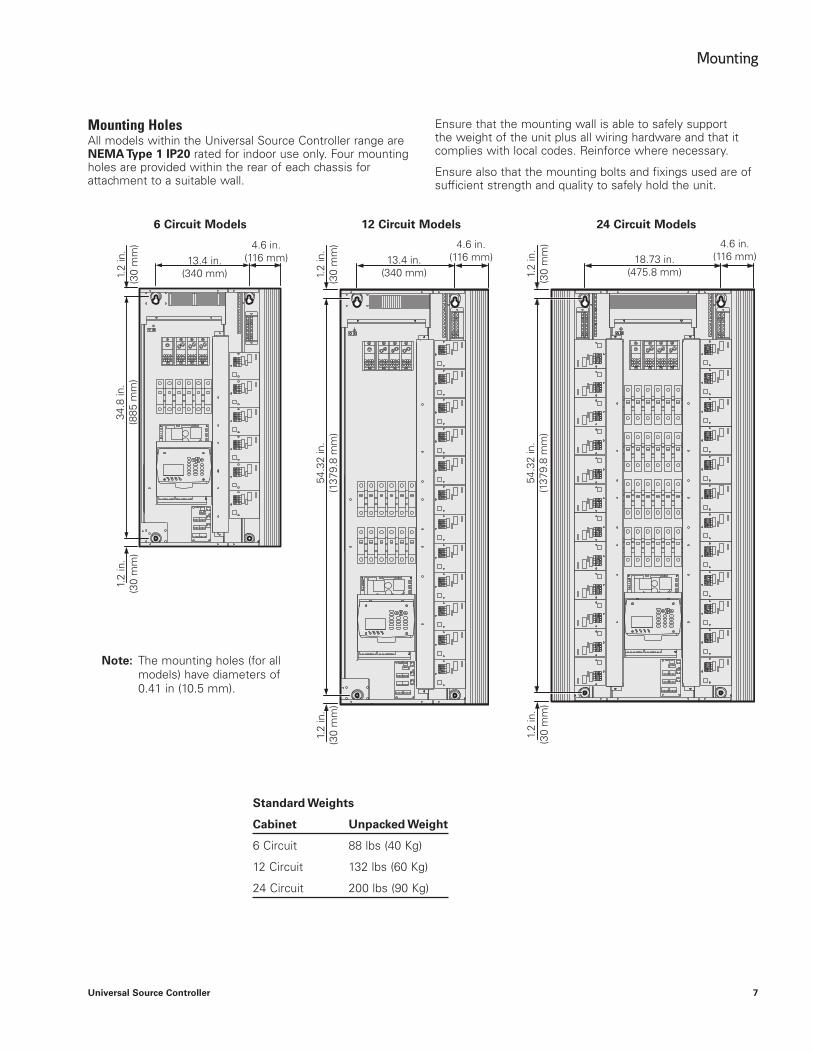
Mounting HolesAll models within the Universal Source Controller range are NEMA Type 1 IP20 rated for indoor use only. Four mounting holes are provided within the rear of each chassis for attachment to a suitable wall.
Ensure that the mounting wall is able to safely support the weight of the unit plus all wiring hardware and that it complies with local codes. Reinforce where necessary.
Ensure also that the mounting bolts and fixings used are of sufficient strength and quality to safely hold the unit.
ES C
1 2
0 EN T
3
4 5 6
7 8 9
#
1.2
in.
(30
mm
)
1.2
in.
(30
mm
)
1.2
in.
(30
mm
)
34.8
in.
(885
mm
)
54.3
2 in
. (1
379.
8 m
m)
54.3
2 in
. (1
379.
8 m
m)
13.4 in. (340 mm)
13.4 in. (340 mm)
18.73 in. (475.8 mm)
4.6 in. (116 mm)
4.6 in. (116 mm)
4.6 in. (116 mm)
1.2
in.
(30
mm
)
1.2
in.
(30
mm
)
1.2
in.
(30
mm
)
ote:N The mounting holes (for all models) have diameters of 0.41 in (10.5 mm).
Standard Weights
Cabinet Unpacked Weight
6 Circuit 88 lbs (40 Kg)
12 Circuit 132 lbs (60 Kg)
24 Circuit 200 lbs (90 Kg)
6 Circuit Models 12 Circuit Models 24 Circuit Models

8
Supply Wiring
Universal Source Controller
Accessing the Mounting HolesThe mounting holes are located within the rear panel of the Source Controller. To access the mounting holes (and circuit wiring terminals) it is necessary to remove the front panels.
To Remove the Front Panels
CAUTION: If removing panels on a previously installed Source Controller, ensure that all power inputs are isolated first.
1. Open the main panel door.
2. Remove the two upper and two lower screws that hold the main panel in place and carefully lift off the complete panel.
3. Now remove the single upper and single lower screw holding the right side panel in place. Carefully lift off the panel.
4. For 24 circuit models, repeat step 3 for the left side panel.
To Replace the Front Panels1. Replace the side panel(s) first. Place the right side
panel onto the chassis and replace the upper and lower fixing screws.
2. For 24 circuit models, repeat step 1 for the left side panel.
3. Place the main panel onto the chassis and open the door. Replace the two upper and two lower fixing screws.
Supply Wiring
Wiring FlowThe Universal Source Controller range has been designed to provide a clear layout and logical progression for all power circuits.
The main supply conductors enter at the top panel and connect directly to the input lugs. Input power is then fed to a central bank of breakers and distributed from there to each of the individual circuit cards.
Two vertical wireways (one for 6 and 12 circuit models) provide clear routes from the circuit card outputs up to the earth terminals and the exit knockouts within the top panel of the chassis.
The diagram shown below indicates a typical wiring flow with the high voltage load wiring from the various channels (and their earth connections) exiting from the top panel.
1
2
3
4
5
6
7
8
9
10
11
12
24
23
22
21
20
19
18
17
16
15
14
13
1 2 3 4 5 6
13 14 15 16 17 18
19 20 21 22 23 24
7 8 9 10 11 12
ESC
1 2
0 EN T
3
4 5 6
7 8 9
#
SUPPLY
Lower Screw for Right Side Panel
Earth Terminal Earth Terminal
Vertical Wireways
Lower Screws for Central Panel
Load Wiring
9
Supply Wiring
Universal Source Controller
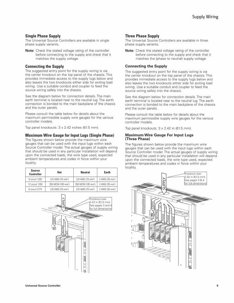
Single Phase SupplyThe Universal Source Controllers are available in single phase supply variants.
ote:N Check the stated voltage rating of the controller before connecting to the supply and check that it matches the supply voltage.
Connecting the SupplyThe suggested entry point for the supply wiring is via the center knockout on the top panel of the chassis. This provides immediate access to the supply lugs below and also leaves the two knockouts either side for exiting load wiring. Use a suitable conduit and coupler to feed the source wiring safely into the chassis.
See the diagram below for connection details. The main earth terminal is located near to the neutral lug. The earth connection is bonded to the main backplane of the chassis and the outer panels.
Please consult the table below for details about the maximum permissible supply wire gauges for the various controller models.
Top panel knockouts: 3 x 2.42 inches (61.5 mm).
Maximum Wire Gauge for Input Lugs (Single Phase) The figures shown below provide the maximum wire gauges that can be used with the input lugs within each Source Controller model. The actual gauges of supply wiring that should be used in any particular installation will depend upon the connected loads, the wire type used, expected ambient temperatures and codes in force within your locality.
Source Controller Hot Neutral Earth
6 circuit 120V 2/0 AWG (70 mm2) 2/0 AWG (70 mm2) 2 AWG (35 mm2)
12 circuit 120V 350 MCM (185 mm2) 350 MCM (185 mm2) 2 AWG (35 mm2)
6 circuit 277V 2/0 AWG (70 mm2) 2/0 AWG (70 mm2) 2 AWG (35 mm2)
SUPP
LY
EART
H
HOT
NEU
TRAL
Three Phase SupplyThe Universal Source Controllers are available in three phase supply variants.
ote:N Check the stated voltage rating of the controller before connecting to the supply and check that it matches the (phase to neutral) supply voltage.
Connecting the SupplyThe suggested entry point for the supply wiring is via the center knockout on the top panel of the chassis. This provides immediate access to the supply lugs below and also leaves the two knockouts either side for exiting load wiring. Use a suitable conduit and coupler to feed the source wiring safely into the chassis.
See the diagram below for connection details. The main earth terminal is located near to the neutral lug. The earth connection is bonded to the main backplane of the chassis and the outer panels.
Please consult the table below for details about the maximum permissible supply wire gauges for the various controller models.
Top panel knockouts: 3 x 2.42 in (61.5 mm).
Maximum Wire Gauge For Input Lugs (Three Phase) The figures shown below provide the maximum wire gauges that can be used with the input lugs within each Source Controller model. The actual gauges of supply wiring that should be used in any particular installation will depend upon the connected loads, the wire type used, expected ambient temperatures and codes in force within your locality.
SUPP
LY
EART
HNEU
TRAL
PHAS
E3
PHAS
E2
PHAS
E1
Knockout size: 2.42 in (61.5 mm) See pages 3 and 4 for full dimensions
Knockout size: 2.42 in (61.5 mm) See pages 3 & 4 for full dimensions

10
Load Wiring
Universal Source Controller
Source Controller Hot Neutral Earth
6 circuit 120V 2/0 AWG (70 mm2) 2/0 AWG (70 mm2) 2 AWG (35 mm2)
12 circuit 120V 2/0 AWG (70 mm2) 2/0 AWG (70 mm2) 2 AWG (35 mm2)
24 circuit 120V 4/0 AWG (120 mm2) 350 MCM (185 mm2) 2 AWG (35 mm2)
6 circuit 277V 2/0 AWG (70 mm2) 2/0 AWG (70 mm2) 2 AWG (35 mm2)
12 circuit 277V 2/0 AWG (70 mm2) 2/0 AWG (70 mm2) 2 AWG (35 mm2)
24 circuit 277V 4/0 AWG (120 mm2) 350 MCM (185 mm2) 2 AWG (35 mm2)
Phase Distribution to CircuitsThe available circuits within each Universal Source Controller are evenly distributed between the three phases, as listed here:
6 Circuit Controllers
Phase 1: Circuits 1, 4
Phase 2: Circuits 2, 5
Phase 3: Circuits 3, 6
12 Circuit Controllers
Phase 1: Circuits 1, 4, 7, 10
Phase 2: Circuits 2, 5, 8, 11
Phase 3: Circuits 3, 6, 9, 12
24 Circuit Controllers
Phase 1: Circuits 1, 4, 7, 10, 13, 16, 19, 22
Phase 2: Circuits 2, 5, 8, 11, 14, 17, 20, 23
Phase 3: Circuits 3, 6, 9, 12, 15, 18, 21, 24
Supply to Internal CircuitryThe internal power supply that feeds the control panel and associated circuitry can draw its power from any and all phases so that it will still operate in the event that not all supply phases are available.
Load Wiring
High Voltage Load WiringEach load channel is served by a dedicated control card fed from a designated circuit breaker. For each card, load connections are made using a four-way rapid connection block.
Available at the connection block are a permanent Hot (subject to circuit breaker status), Switched hot (via relay control), Dimmed hot (via triac control) and Neutral - see diagram below.
ote:N Earth connections for each channel are made using the connector blocks located at the top of each wireway.
When supplied, a red 3-way bypass jumper is installed within each connection block to serve three purposes:
●● To bind the three outputs in order to protect each channel card from load faults during installation
●● To energize each channel output (subject to the status of the associated circuit breaker) for use as work lighting control during installation and
●● To assist with circuit testing during commissioning
IMPORTANT: The bypass jumper must remain in place on each channel until the commissioning process is complete.
Dimmed Hot NeutralSwitched
HotHot (Live)
Bypass Jumper
Maximum Wire GaugesSolid Wire: 10 AWG (6 mm2)Stranded Wire: 12 AWG (4 mm2)
11
Load Wiring
Universal Source Controller
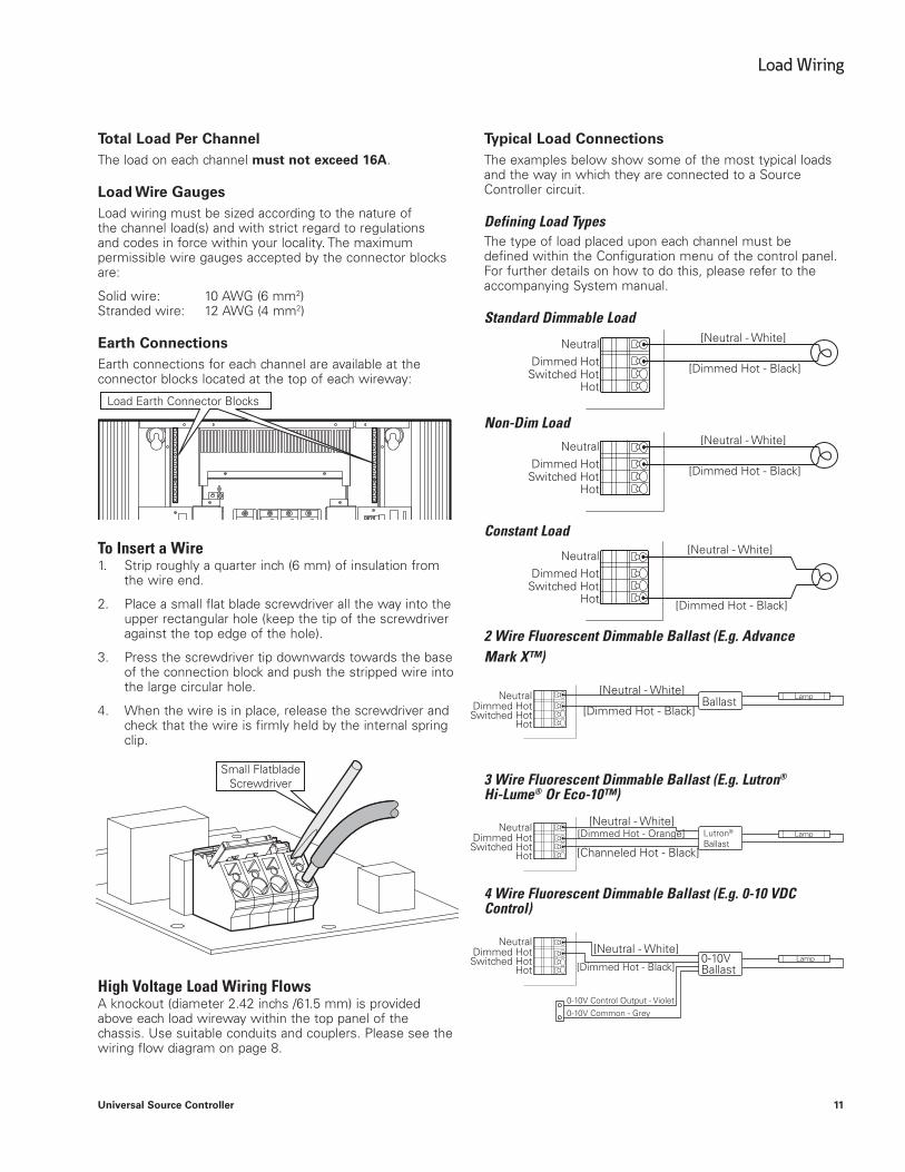
Total Load Per ChannelThe load on each channel must not exceed 16A.
Load Wire Gauges Load wiring must be sized according to the nature of the channel load(s) and with strict regard to regulations and codes in force within your locality. The maximum permissible wire gauges accepted by the connector blocks are:
Solid wire: 10 AWG (6 mm2) Stranded wire: 12 AWG (4 mm2)
Earth ConnectionsEarth connections for each channel are available at the connector blocks located at the top of each wireway:
To Insert a Wire 1. Strip roughly a quarter inch (6 mm) of insulation from
the wire end.
2. Place a small flat blade screwdriver all the way into the upper rectangular hole (keep the tip of the screwdriver against the top edge of the hole).
3. Press the screwdriver tip downwards towards the base of the connection block and push the stripped wire into the large circular hole.
4. When the wire is in place, release the screwdriver and check that the wire is firmly held by the internal spring clip.
High Voltage Load Wiring FlowsA knockout (diameter 2.42 inchs /61.5 mm) is provided above each load wireway within the top panel of the chassis. Use suitable conduits and couplers. Please see the wiring flow diagram on page 8.
Typical Load ConnectionsThe examples below show some of the most typical loads and the way in which they are connected to a Source Controller circuit.
Defining Load TypesThe type of load placed upon each channel must be defined within the Configuration menu of the control panel. For further details on how to do this, please refer to the accompanying System manual.
Standard Dimmable Load
Non-Dim Load
Constant Load
2 Wire Fluorescent Dimmable Ballast (E.g. Advance Mark X™)
3 Wire Fluorescent Dimmable Ballast (E.g. Lutron® Hi-Lume® Or Eco-10™)
4 Wire Fluorescent Dimmable Ballast (E.g. 0-10 VDC Control)
Load Earth Connector Blocks
[Neutral - White]
[Neutral - White]
[Neutral - White]
[Neutral - White]
[Neutral - White]
[Neutral - White]
Ballast
Lutron®
Ballast
0-10V Ballast
Lamp
Lamp
Lamp
[Dimmed Hot - Black]
[Dimmed Hot - Black]
[Dimmed Hot - Black]
[Dimmed Hot - Black]
[Channeled Hot - Black]
0-10V Control Output - Violet0-10V Common - Grey
[Dimmed Hot - Orange]
[Dimmed Hot - Black]
Neutral
Neutral
Neutral
Neutral
Neutral
Neutral
Dimmed Hot
Dimmed Hot
Dimmed Hot
Dimmed Hot
Dimmed Hot
Dimmed Hot
Switched Hot
Switched Hot
Switched Hot
Switched Hot
Switched Hot
Switched Hot
Hot
Hot
Hot
Hot
Hot
Hot
Small Flatblade Screwdriver

12
Load Wiring
Universal Source Controller
Low Voltage Load WiringEach channel can be individually configured to support any of the following low voltage load control standards: 0-10V, DSI or broadcast DALI (DSI and DALI - Canada and Mexico Only). The high voltage sections for each channel continue to provide switched hot outputs to power the controlled loads.
ote:N Support for multiple low voltage load control standards may not be permissible in certain countries. In such cases, the required control standard must be stated when ordering.
The low voltage load wiring circuits are located just below the control panel, accessible either through a removable mini panel or when the complete casing is removed.
Connections are made easy by using removable plug blocks which snap into terminals mounted on the circuit boards shown below:
sign
al
sign
al
sign
al
sign
al
1 7
13 19
2 8
14 20
3 9
15 21
4 10
16 22
5 11
17 23
6 12
18 24
0V 0V
0V 0V
sign
al
sign
al
sign
al
sign
al
0V 0V
0V 0V
sign
al
sign
al
sign
al
sign
al
0V 0V
0V 0V
sign
al
sign
al
sign
al
sign
al
0V 0V
0V 0V
sign
al
sign
al
sign
al
sign
al
0V 0V
0V 0V
sign
al
sign
al
sign
al
sign
al
0V 0V
0V 0V
For each circuit, the low voltage control protocol to be used is selected using the configuration menu on the control panel. The programming of the Source Controller channels is covered within the accompanying System Manual.
ote:N DALI signals for each channel are output in broadcast mode only - it is not possible to individually address multiple DALI luminaires on the same control wire.
The low voltage load control circuits are PELV (Protected Extra Low Voltage).
Low Voltage Load Wiring FlowsThe casing provides four knockouts on the base panel for use by exiting low voltage load cables as well as control wiring. Each knockout is 0.89 inches (22.5 mm) in diameter.
Use appropriate conduits and couplers to link with raceways or cable runs, as necessary.
IMPORTANT: Low voltage load wiring should be installed with a suitable separation to parallel high voltage cables, according to local and national codes.
IndicatorsAn indicator is assigned to each low voltage output channel to provide quick visual feedback. In each case, the indicator (located next to the output connectors) will mimic the dimmed status of the associated channel, from zero to full brightness.
Indicators

13
Control Wiring
Universal Source Controller
Control Wiring
Multiple Control ProtocolsTo ensure maximum versatility, the Universal Source Controllers provide full compatibility with a range of control protocols, including:
●● iCAN bus
●● DMX512A
●● RS-485
●● Ethernet
Connections for the iCAN bus, DMX512A and RS-485 protocols are made using removable plug blocks which snap into terminals mounted on the control circuit board. A standard RJ45 socket is provided for the ethernet connection.
In addition, a separate connector block (labeled ‘Contact closure’) allows two volt-free switch inputs from external systems. Subject to configuration menu settings, these inputs can be used to affect selected channels.
The control connections are located just below the control panel, accessible either through a removable mini panel or when the complete casing is removed.
TerminationThe iCAN, DMX and RS-485 are ‘daisy-chain’ protocols that all require termination on the devices located at either end of the chain.
The Switched Relay Controller provide jumper links adjacent to the iCAN, DMX and RS-485 connectors. As standard, all of these interfaces are terminated. To remove termination for a particular bus, move the associated termination jumper from the upper two pins to the lower two pins.
DMX+
RS-485- RS-485+
DMX- OV
OV
Shield
Shield
Ethernet Link
+12V (Red)
CAN-H (White)
Drain (Gray)
CAN-L (Blue)
0V (Black)
DMX
Contact Closure
iCAN
Switch Input 1
Switch Input 2
RS-485
TERM
Termination ON
Device Device Device Universal Source
Controller
T
T
Termination OFF
TERM
14
Control Panel Operation
Universal Source Controller
Control Panel Operation
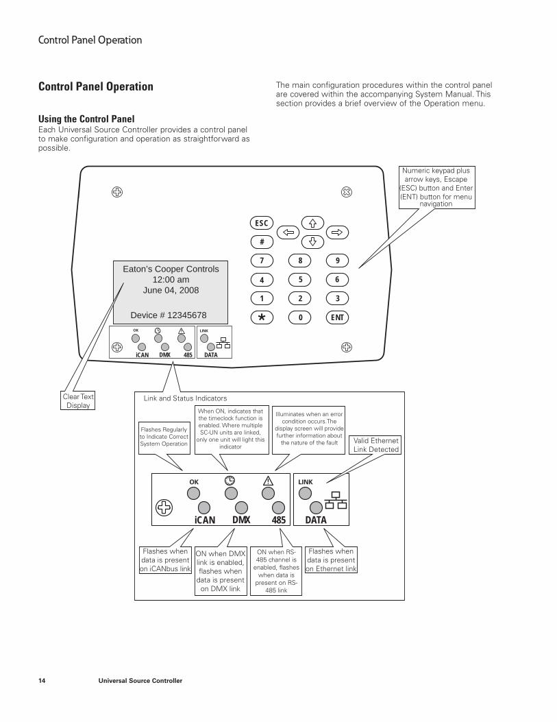
Using the Control PanelEach Universal Source Controller provides a control panel to make configuration and operation as straightforward as possible.
iCAN DMX 485
ESC
ENT
#
1
4
7 8 9
5 6
2
0
3
DATA
Eaton’s Cooper Controls12:00 am
June 04, 2008
Device # 12345678
iCAN DMX 485 DATA
The main configuration procedures within the control panel are covered within the accompanying System Manual. This section provides a brief overview of the Operation menu.
OK
OK LINK
LINK
Numeric keypad plus arrow keys, Escape
(ESC) button and Enter (ENT) button for menu
navigation
Clear Text Display
Link and Status Indicators
Flashes Regularly to Indicate Correct System Operation
When ON, indicates that the timeclock function is enabled. Where multiple SC-UN units are linked,
only one unit will light this indicator
Illuminates when an error condition occurs.The
display screen will provide further information about
the nature of the fault Valid Ethernet Link Detected
Flashes when data is present on Ethernet link
Flashes when data is present on iCANbus link
ON when RS-485 channel is
enabled, flashes when data is
present on RS-485 link
ON when DMX link is enabled, flashes when
data is present on DMX link
15
Control Panel Operation
Universal Source Controller
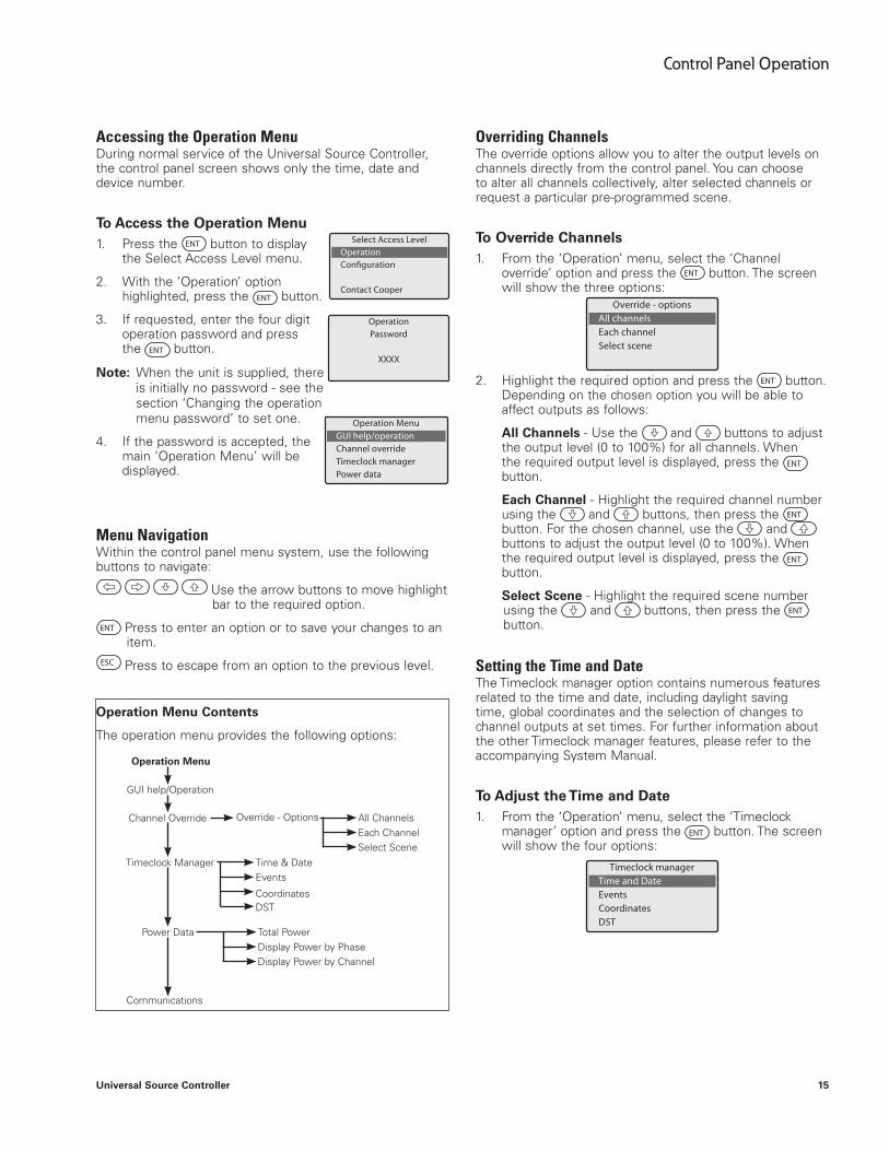
Accessing the Operation MenuDuring normal service of the Universal Source Controller, the control panel screen shows only the time, date and device number.
To Access the Operation Menu1. Press the ENT button to display
the Select Access Level menu.
2. With the ‘Operation’ option highlighted, press the ENT button.
3. If requested, enter the four digit operation password and press the ENT button.
ote:N When the unit is supplied, there is initially no password - see the section ‘Changing the operation menu password’ to set one.
4. If the password is accepted, the main ‘Operation Menu’ will be displayed.
Menu NavigationWithin the control panel menu system, use the following buttons to navigate:
Use the arrow buttons to move highlight bar to the required option.
ENT Press to enter an option or to save your changes to an item.
ESC Press to escape from an option to the previous level.
Operation Menu Contents
The operation menu provides the following options:
Overriding ChannelsThe override options allow you to alter the output levels on channels directly from the control panel. You can choose to alter all channels collectively, alter selected channels or request a particular pre-programmed scene.
To Override Channels1. From the ‘Operation’ menu, select the ‘Channel
override’ option and press the ENT button. The screen will show the three options:
Override - options All channels Each channel Select scene
2. Highlight the required option and press the ENT button. Depending on the chosen option you will be able to affect outputs as follows:
All Channels - Use the and buttons to adjust the output level (0 to 100%) for all channels. When the required output level is displayed, press the ENT button.
Each Channel - Highlight the required channel number using the and buttons, then press the ENT button. For the chosen channel, use the and buttons to adjust the output level (0 to 100%). When the required output level is displayed, press the ENT button.
Select Scene - Highlight the required scene number using the and buttons, then press the ENT button.
Setting the Time and DateThe Timeclock manager option contains numerous features related to the time and date, including daylight saving time, global coordinates and the selection of changes to channel outputs at set times. For further information about the other Timeclock manager features, please refer to the accompanying System Manual.
To Adjust the Time and Date1. From the ‘Operation’ menu, select the ‘Timeclock
manager’ option and press the ENT button. The screen will show the four options:
Timeclock manager Time and Date Events Coordinates DST
GUI help/Operation
Operation Menu
Channel Override Override - Options All Channels
Total Power
Time & Date
CoordinatesDST
Events
Each Channel
Display Power by Phase
Select Scene
Display Power by Channel
Timeclock Manager
Power Data
Communications
Operation Menu GUI help/operation Channel override Timeclock manager Power data
Select Access Level Operation
Contact Cooper
Operation Password
XXXX
16
Control Panel Operation
Universal Source Controller
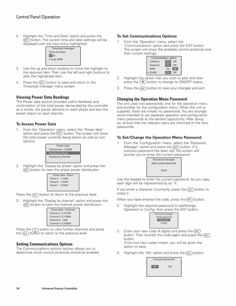
2. Highlight the ‘Time and Date’ option and press the ENT button. The current time and date settings will be
displayed with the hour entry highlighted:Timeclock manager
Time and Date 13:26 2 June 2008
3. Use the up and down buttons to move the highlight to the required item. Then use the left and right buttons to alter the highlighted item.
4. Press the ENT button to save and return to the Timeclock manager menu screen.
Viewing Power Data ReadingsThe Power data section provides useful feedback and confirmation of the total power demanded by the controller as a whole, the power demand on each phase and also the power drawn on each channel.
To Access Power Data1. From the ‘Operation’ menu, select the ‘Power data’
option and press the ENT button. The screen will show the total power currently being drawn as well as two options:
Power data Total power 2.39kW Display by phase Display by channel
2. Highlight the ‘Display by phase’ option and press the ENT button to view the phase power distribution:
Power data - Phase Phase A 1.75kW Phase B 1.65kW Phase C 0.95kW
Press the ESC button to return to the previous level.
3. Highlight the ‘Display by channel’ option and press the ENT button to view the channel power distribution:
Power data - Channels Channel 1: 0.101kW Channel 2: 0.130kW Channel 3: 0kW Channel 4: 0.500kW
Press the button to view further channels and press the ESC button to return to the previous level.
Setting Communications OptionsThe Communications options section allows you to determine which control protocols should be enabled.
To Set Communications Options1. From the ‘Operation’ menu, select the
‘Communications’ option and press the ENT button. The screen will show the available control protocols and their current settings:
v
Communications - options iCANnet On Ethernet On DMX On RS485 On
2. Highlight the option that you wish to alter and then press the button to change its ON/OFF status.
3. Press the ENT button to save your changes and exit.
Changing the Operation Menu PasswordThe unit uses two passwords, one for the operation menu and another for the configuration menu. When the unit is supplied, there are initially no passwords. You are strongly recommended to set separate operation and configuration menu passwords at the earliest opportunity. After doing so, ensure that the relevant users are informed of the new passwords.
To Set/Change the Operation Menu Password1. From the ‘Configuration’ menu, select the ‘Password
Manager’ option and press the ENT button. If a previous password has been set, the screen will prompt you to enter the current password:
Password managerEnter current password
XXXX
Use the keypad to enter the current password. As you type, each digit will be represented by an ‘X’.
If you enter a character incorrectly, press the ESC button to erase it.
When you have entered the code, press the ENT button.
2. Highlight the required password to set/change: Operation or Config, then press the ENT button.
Password managerChoose password
OperationConfig
3. Enter your new code (4 digits) and press the ENT button. Then re-enter the code again and press the ENT button. If the two new codes match, you will be given the option to save.
4. Highlight the ‘Yes’ option and press the ENT button.
Change password?
Yes No

Eaton1000 Eaton BoulevardCleveland, OH 44122United StatesEaton.com
Eaton’s Cooper Controls Business203 Cooper CirclePeachtree City, GA 30269CooperControl.com
© 2014 EatonAll Rights ReservedPrinted in USAP/N: 9850-000020-01
Eaton is a registered trademark.
All trademarks are property of their respective owners.
WARRANTIES AND LIMITATION OF LIABILITY
Please refer to www.coopercontrol.com under the Legal section for our terms and conditions.