Model PB¼ Type 3 - John Brooks
15
pb025nmdl3sm-rev0316 Table of Contents Engineering Data and Temperature Limitations .................... 1 Performance Curve ............................................................... 1 Explanation of Pump Nomenclature ...................................... 2 Dimensions ............................................................................ 3 Metric Dimensions ................................................................. 4 Principle of Pump Operation.................................................. 5 Check Valve Servicing ........................................................... 5 Diaphragm Servicing ............................................................. 5 Troubleshooting ..................................................................... 6 Warranty ................................................................................ 6 Material Codes ...................................................................... 7 Installation Guide ................................................................... 7 Composite Repair Parts Drawing .......................................... 8 Available Service and Conversion Kits .................................. 8 Composite Repair Parts List .................................................. 9 Grounding the Pump ............................................................. 9 Solenoid Shifted Option Drawing......................................... 10 Solenoid Shifted Air Valve Parts List ................................... 10 Solenoid Shifted Options ..................................................... 11 Solenoid Connector Drawing ............................................... 11 CE Declaration of Conformity - Machinery .......................... 12 CE Declaration of Conformity - ATEX .................................. 13 Warren Rupp, Inc., • A Unit of IDEX Corporation • 800 N. Main St., Mansfield, Ohio 44902 USA Telephone (419) 524-8388 • Fax (419) 522-7867 • warrenrupp.com Model PB¼ Type 3 Air-Operated Double Diaphragm Pump SERVICE & OPERATING MANUAL Original Instructions See pages 2, 13 and for ATEX ratings.
Transcript of Model PB¼ Type 3 - John Brooks

pb025nmdl3sm-rev0316
Table of ContentsEngineering Data and Temperature Limitations ....................1Performance Curve ...............................................................1Explanation of Pump Nomenclature ......................................2Dimensions ............................................................................3Metric Dimensions .................................................................4Principle of Pump Operation..................................................5Check Valve Servicing ...........................................................5Diaphragm Servicing .............................................................5Troubleshooting .....................................................................6Warranty ................................................................................6Material Codes ......................................................................7Installation Guide ...................................................................7Composite Repair Parts Drawing ..........................................8Available Service and Conversion Kits ..................................8Composite Repair Parts List ..................................................9Grounding the Pump .............................................................9Solenoid Shifted Option Drawing.........................................10Solenoid Shifted Air Valve Parts List ...................................10Solenoid Shifted Options .....................................................11Solenoid Connector Drawing ...............................................11CE Declaration of Conformity - Machinery ..........................12CE Declaration of Conformity - ATEX ..................................13
Warren Rupp, Inc., • A Unit of IDEX Corporation • 800 N. Main St., Mansfield, Ohio 44902 USA Telephone (419) 524-8388 • Fax (419) 522-7867 • warrenrupp.com
Model PB¼Type 3Air-Operated Double Diaphragm Pump
SERVICE & OPERATING MANUALOriginal Instructions
See page 2 for ATEX ratings.
See pages 2, 13 and for ATEX ratings.

IMPORTANT
Read the safety warnings and instructions in this manual before pump installation and start-up. Failure to comply with the recommendations stated in this manual could damage the pump and void factory warranty.
When used for toxic or aggressive fluids, the pump should always be flushed clean prior to disassembly.
Airborne particles and loud noise hazards. Wear eye and ear protection.
Before maintenance or repair, shut off the compressed air line, bleed the pressure, and disconnect the air line from the pump. Be certain that approved eye protection and protective clothing are worn at all times. Failure to follow these recommendations may result in serious injury or death.
ATEX compliant pumps are suitable for use in explosive atmospheres when the equipment is properly grounded in accordance with local electrical codes. Pumps equipped with electrically conductive diaphragms are suitable for the transfer of conductive or non-conductive fluids of any explosion group. When operating pumps equipped with non-conductive diaphragms that exceed the maximum permissible projected area, as defined in EN 13461-1: 2009 section 6.7.5 table 9, the following protection methods must be applied:
• Equipment is always used to transfer electrically conductive fluids or• Explosive environment is prevented from entering the internal portions of the pump, i.e. dry running
For further guidance on ATEX applications, please consult the factory.
When the pump is used for materials that tend to settle out or solidify, the pump should be flushed after each use to prevent damage. In freezing temperatures the pump should be completely drained between uses.
Before pump operation, inspect all fasteners for loosening caused by gasket creep. Retighten loose fasteners to prevent leakage. Follow recommended torques stated in this manual.
CAUTION
WARNING
Nonmetallic pumps and plastic components are not UV stabilized. Ultraviolet radiation can damage these parts and negatively affect material properties. Do not expose to UV light for extended periods of time.
In the event of diaphragm rupture, pumped material may enter the air end of the pump, and be discharged into the atmosphere. If pumping a product that is hazardous or toxic, the air exhaust must be piped to an appropriate area for safe containment.
This pump is pressurized internally with air pressure during operation. Make certain that all fasteners are in good condition and are reinstalled properly during reassembly.
Take action to prevent static sparking. Fire or explosion can result, especially when handling flammable liquids. The pump, piping, valves, containers and other miscellaneous equipment must be properly grounded.
Safety Information
Grounding ATEX Pumps
Use safe practices when liftingkg
RECYCLING Many components of SANDPIPER® AODD pumps are made of recyclable materials. We encourage pump users to recycle worn out parts and pumps whenever possible, after any hazardous pumped fluids are thoroughly flushed.
pb025nmdl3sm-rev0316 Page 1
Model PB¼ Type 3
Air-Operated Double Diaphragm Pump
Engineering, Performance & Construction Data
Quality SystemISO 9001 Certified
Environmental Man-agement System ISO
14001 Certified
Materials
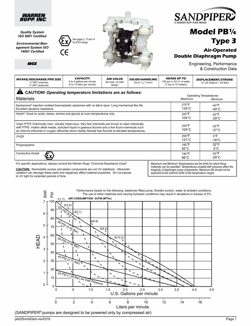
INTAKE/DISCHARGE PIPE SIZE¼" NPT (internal)½" NPT (external)
CAPACITY0 to 4 gallons per minute(0 to 15 liters per minute)
AIR VALVENo-lube, no-stall
design
SOLIDS-HANDLINGUp to 1/32" (1mm)
HEADS UP TO100 psi or 231 ft. of water
(7 bar or 70 meters)
DISPLACEMENT/STROKE.01 US Gallons / .04 liters
MaximumOperating Temperatures
Minimum
Santoprene® Injection molded thermoplastic elastomer with no fabric layer. Long mechanical flex life. Excellent abrasion resistance.
Hytrel®: Good on acids, bases, amines and glycols at room temperatures only.
Polypropylene
PVDF
Virgin PTFE Chemically inert, virtually impervious. Very few chemicals are known to react chemically with PTFE: molten alkali metals, turbulent liquid or gaseous fluorine and a few fluoro-chemicals such as chlorine trifluoride or oxygen difluoride which readily liberate free fluorine at elevated temperatures.
Conductive Acetal
275°F 135°C
-40°F -40°C
220°F 104°C
220°F 104°C
250°F 121°C180°F 82°C190°F 88°C
-35°F -37°C
-20°F -29°C
0°F -18°C
CAUTION! Operating temperature limitations are as follows:
-20°F -29°C
32°F 0°C
II 2GD T5
100
90
80
70
60
50
40
30
20
10
0 .5 1.0 2.5 3.0 3.5 4.0 4.51.5 2.0
1
2
3
4
5
6
7
0
0 2 4 6 8 10 12 14 16
0
1(1.7)
2(3.4)
3(5.1)
4(6.8)
5(8.5)
6(10.2)
CAPACITYLiters per minute
U.S. Gallons per minute
BAR
PSI
HEA
D
100 PSI (6.8 Bar)80 PSI (5.44 Bar)
60 PSI (4.08 Bar)
40 PSI (2.72 Bar)
20 PSI (1.36 Bar) Air Inlet Pressure
AIR CONSUMPTION SCFM (M3/hr)
MODEL PB¼-A Performance CurvePerformance based on the following: elastomer fitted pump, flooded suction, water at ambient conditions.
The use of other materials and varying hydraulic conditions may result in deviations in excess of 5%.
(SANDPIPER® pumps are designed to be powered only by compressed air)
CAUTION: Nonmetallic pumps and plastic components are not UV stabilized. Ultraviolet radiation can damage these parts and negatively affect material properties. Do not expose to UV light for extended periods of time.
See page 2 for ATEX ratings.
See pages 2, 13 and 14 for ATEX ratings.
Maximum and Minimum Temperatures are the limits for which these materials can be operated. Temperatures coupled with pressure affect the longevity of diaphragm pump components. Maximum life should not be expected at the extreme limits of the temperature ranges.
For specific applications, always consult the Warren Rupp “Chemical Resistance Chart”

pb025nmdl3sm-rev0316 Page 2
Explanation of Pump Nomenclature
ATEX Detail
Your Serial #: (fill in from pump nameplate) _____________________________________
__ __ _____ __ ___ __ __
Pump Pump Pump Size Discharge Diaphragm/ Design Construction Series Design and Options Porting Valve Level
XX X XXXXXX, XX XXX X XXModel #:
(fill in from pump nameplate)
Your Model #:
Discharge Porting Position T Top H Horizontal Suction and Discharge V Vertical Discharge VV Vertical Suction and Discharge
Diaphragm Check Valve Materials S Santoprene T Virgin PTFE U Santoprene Diaphragms/PTF E Ball
Design Level 3
Construction P Polypropylene Wet End and Center K PVDF Wet End and Polypropylene Center CA Conductive Acetal Wet End and Center
Pump Series P Plastic
Pump Design B Soilid Ball
Pump Size and Options 1/4 1/4" NPT P1 Intrinsically Safe ATEX Compliant Pulse Output P0 10-30VDC Pulse Output Option P2 110/120 or 220/240VAC Pulse Output Option E0 Integral Solenoid 24VDC Coil E1 Integral Solenoid 24VDC Explosion-Proof Coil E2 Integral Solenoid 24VAC/12VDC Coil E3 Integral Solenoid 12VDC Explosion-Proof Coil E4 Integral Solenoid 110VAC Coil E5 Integral Solenoid 110VAC Explosion-Proof Coil E6 Integral Solenoid 220VAC Coil E7 Integral Solenoid 220VAC Explosion-Proof Coil E8 Integral Solenoid 115VAC, 50Hz Explosion- Proof Coil E9 Integral Solenoid 230VAC, 50Hz, Explosion- Proof Coil
ATEX Detail Construction Muffler Options OptionsII 1G c T5 II 1D c T100°C I M1 c I M2 c
CA Metal 00
II 2G c T5 II 2D c T100°C CA Integral 00
II 2G Ex ia c II T5 II 2D Ex c iaD 20 IP67 T100°C
CA Integral P1
II 2GD T5

pb025nmdl3sm-rev0316 Page 3
Dimensions: PB¼ Non-Metallic
Dimension
Standard
Pulse Output Kit
A B C
7" 3 1/8" 5 1/2"
7" 3 1/8" 5 1/2"

pb025nmdl3sm-rev0316 Page 4
Metric Dimensions: PB¼ Non-Metallic
Dimension
Standard
Pulse Output Kit
A B C
178 79 140
178 79 140

pb025nmdl3sm-rev0316 Page 5
PRINCIPLE OF PUMP OPERATIONThis ball type check valve pump is
powered by compressed air and is a 1:1 ratio design. The inner side of one diaphragm chamber is alternately pressurized whi le simultaneously exhausting the other inner chamber. This causes the diaphragms, which are connected by a common rod secured by plates to the centres of the diaphragms, to move in a reciprocating action. (As one diaphragm performs the discharge stroke the other diaphragm is pulled to perform the suction stroke in the opposite chamber.) Air pressure is applied over the entire inner surface of the diaphragm while liquid is dis-charged from the opposite side of the diaphragm. The diaphragm operates in a balanced condition during the discharge stroke which allows the pump to be operated at discharge heads over 200 feet (61 meters) of water.
For maximum diaphragm life, keep the pump as close to the liquid being pumped as possible. Positive suction head in excess of 10 feet of liquid (3.048 meters) may require a back pressure regulating device to maximize diaphragm life.
Alternate pressurizing and exhausting of the diaphragm chamber is performed by an externally mounted, pilot operated, four way spool type air distribution valve. When the spool shifts to one end of the valve body, inlet pressure is applied to one diaphragm chamber and the other diaphragm chamber exhausts. When the spool shifts to the opposite end of the valve body, the pressure to the chambers is reversed. The air distribution valve spool is moved by a internal pilot valve which alternately pressurizes one end of the air distribution valve spool while exhausting the other end. The pilot valve is shifted at each end of the dia-
phragm stroke when a actuator plunger is contacted by the diaphragm plate. This actuator plunger then pushes the end of the pilot valve spool into position to activate the air distribution valve.
The chambers are connected with manifolds with a suction and discharge check valve for each chamber, maintaining flow in one direction through the pump.
INSTALLATION AND START-UPLocate the pump as close to the
product being pumped as possible. Keep the suction line length and number of fittings to a minimum. Do not reduce the suction line diameter.
For installations of rigid piping, short sections of flexible hose should be installed between the pump and the piping. The f lexible hose reduces vibration and strain to the pumping sys tem. A su rge suppresso r i s recommended to fu r ther reduce pulsation in flow.
AIR SUPPLYAir supply pressure cannot exceed
100 psi (7 bar). Connect the pump air inlet to an air supply of sufficient capacity and pressure required for desired performance. When the air supply line is solid piping, use a short length of flexible hose not less than 1/2" (13mm) in diameter between the pump and the piping to reduce strain to the piping. The weight of the air supply line, regulators and filters must be supported by some means other than the air inlet cap. Failure to provide support for the piping may result in damage to the pump. A pres-sure regulating valve should be installed to insure air supply pressure does not exceed recommended limits.
AIR VALVE LUBRICATIONThe air distribution valve and the
pilot valve are designed to operate WITHOUT lubrication. This is the pre-ferred mode of operation. There may be instances of personal preference or poor quality air supplies when lubrication of the compressed air supply is required. The pump air system will operate with properly lubricated compressed air supply. Proper lubrication requires the use of an air line lubricator (available from Warren Rupp) set to deliver one drop of SAE 10 non-detergent oil for every 20 SCFM (9.4 liters/sec.) of air the pump consumes at the point of operation. Consult the pump’s published Performance Curve to determine this.
AIR LINE MOISTUREWater in the compressed air supply
can create problems such as icing or freezing of the exhaust air, causing the pump to cycle erratically or stop operating. Water in the air supply can be reduced by using a point-of-use air dryer to supplement the user ’s air drying equipment. This device removes water from the compressed air supply and alleviates the icing or freezing problems.
AIR INLET AND PRIMINGTo start the pump, open the air valve
approximately ½ to ¾ turn. After the pump primes, the air valve can be opened to increase air flow as desired. If opening the valve increases cycling rate, but does not increase the rate of flow, cavitation has occurred. The valve should be closed slightly to obtain the most efficient air flow to pump flow ratio.
BETWEEN USESWhen the pump is used for materials
that tend to settle out or solidify when not in motion, the pump should be flushed after each use to prevent damage. (Product remaining in the pump be-tween uses could dry out or settle out. This could cause problems with the diaphragms and check valves at restart.) In freezing temperatures the pump must be completely drained between uses in all cases.
Figure 1
Figure 2
Figure 3
CHECK VALVE SERVICINGNeed for inspection or service is
usually indicated by poor priming, unstable cycling, reduced performance or the pump's cycling but not pumping.
Remove the sixteen machine screws securing the manifold assemblies to the outer chambers. Inspect the surfaces of both check valve and seat for wear or damage that could prevent proper sealing. If pump is to prime properly, valves must seat air tight.
DIAPHRAGM SERVICINGRemove the two V-Band clamps
securing the outer chambers to the intermediate housing. Remove the diaphragm assembly (outer plate, diaphragm, inner plate) by turning the assembly counterclockwise using a 1/2" (1.27 cm) wrench on the outer plate lugs. (If a socket is used, it must be a six point socket.) The interior components consisting of the shaft seal and pilot valve assembly are now accessible for service.
Procedures for reassembling the diaphragms are the reverse of the above. Install the diaphragm with the natural bulge outward.
Install the outer diaphragm plate on the outside of the diaphragm and make certain that the large radius side of the inner plate is toward the diaphragm. Tighten the outer diaphragm plate to approximately 30 in./lbs. (3.39 Newton meters).
Torque while allowing the diaphragm to turn freely with plates. Use a wrench on the outer diaphragm plate of the
Figure 4
opposite side to keep rod from rotating. If the opposite chamber is assembled, the rod need not be held.
EXTERNALLY SERVICEABLE MAIN AIR DISTRIBUTION VALVE
To service the main air distribution, first shut-off and disconnect the air supply to the pump. Remove the four long hex cap screws and hex nuts (on opposite side of pump) which fasten the main air valve body (item 1), gaskets (item 8 and 11), muffler (item 14), and caps (item 6 and 15) to the pump.
Once the main air valve body is off the pump remove the retaining rings (items 7) that hold the end caps in place. Remove the end caps (items 6) to inspect the spool and sleeve. Remove the main air spool (part of item 2) and inspect for damage or wear. Inspect the inside diameter of the main air valve (item 2) for dirt, scratches, or other contaminants. Remove and replace the sleeve if needed. When reinstalling the sleeve, apply a light coating of grease to the six o-rings (item 3) before inserting the sleeve into the main air valve body. Align the holes in the sleeve with the slots in main valve body, making sure the sleeve is centered in the bore. Clean the main air valve spool, lightly grease the o-rings, and insert into the sleeve flush to one end. Reinstall the end caps and retaining rings. The main air valve body is now ready to put back on the pump.
Assemble the air inlet cap (item 9), valve body gasket (item 8), to the main air valve body (making sure the five rect-angular slots face the air inlet cap), and the intermediate gasket onto the four hex
capscrews and install onto the pump. Slide the muffler (item 14) and the exhaust cap (item 15) over the capscrews. Re-install the washers (item 10) and hex nuts (items 16) onto the four hex capscrews and torque to 30 in/lbs. (3.39 Newton meters).
SERVICING THE PILOT VALVETo remove the pilot valve spool (item
23) first remove the end o-ring (item 24) from one end of spool. Slide the spool out of the sleeve and inspect the five remaining o-rings (items 24) for damage or wear. If necessary, replace damaged o-rings. Inspect the inner diameter of pilot valve sleeve (item 20) for scratches, dirt, or other contaminants. Replace the sleeve if necessary. To remove the sleeve first remove the retaining ring from one end. When installing a pilot valve sleeve first lightly grease the six o-rings (items 21). Insert the sleeve into the chamfered end of bore on the intermediate bracket (item 13). Push the sleeve in until the shoulder is flush to intermediate bracket surface and install the retaining ring (item 22). To install the pilot valve spool first lightly grease the four interior o-rings and insert into the pilot valve sleeve. After insert-ing the spool into the sleeve install the remaining loose o-rings onto spool.
SERVICING DIAPHRAGM ROD SEALSTo service the rod seals (item 18)
first remove pilot valve, then remove the inserts on each of the intermediate brackets (item 17) by prying them out with a small flat screwdriver. After removing the inserts take the K-R rod seals out of the inserts and replace. When reinstalling the seals, make sure
the open side of the seals face into the counterbore in the inserts. To install the inserts into intermediate bracket, simply press the insert into the counterbore in each of the intermediate bracket, making sure that the closed side of insert faces out. The inserts should be flush to the surface of the intermediate bracket or slightly below the surface when fully installed.

pb025nmdl3sm-rev0316 Page 6
TROUBLESHOOTINGPossible Symptoms:• Pump will not cycle.• Pump cycles, but produces no
flow.• Pump cycles, but flow rate is
unsatisfactory.• Pump cycle seems unbalanced.• Pump cycle seems to produce
excessive vibration.
What to Check: Excessive suction lift in system.C o r r e c t i v e A c t i o n : F o r l i f t s exceeding 20 feet (6 meters), filling the pumping chambers with liquid will prime the pump in most cases.
What to Check: Excessive flooded suction in system.Corrective Action: For flooded cond i t i ons exceed ing 10 fee t (3 meters) of liquid, install a back pressure device.
What to Check: System head exceeds air supply pressure.Corrective Action: Increase the inlet air pressure to the pump. Most diaphragm pumps are designed for 1:1 pressure ratio at zero flow.
What to Check: Air supply pressure or volume exceeds system head.Corrective Action: Decrease in-let air pressure and volume to the pump as calculated on the published PERFORMANCE CURVE. Pump is cavitating the fluid by fast cycling.
What to Check: Undersized suction line.Corrective Action: Meet or exceed pump connection recommenda-tions shown on the DIMENSIONAL DRAWING.
What to Check: Restr ic ted or undersized air line.Corrective Action: Install a larger air line and connection. Refer to air inlet recommendations shown in your pump’s SERVICE MANUAL.
What to Check: Check ESADS, the Externally Serviceable Air Distribution System of the pump.Corrective Action: Disassemble and inspect the main air distribution valve, pilot valve and pilot valve actuators. Refer to the parts drawing and air valve section of the SERVICE MANUAL. Check for clogged discharge or closed valve before reassembly.
W h a t t o C h e c k : R i g i d p i p e connections to pump.Corrective Action: Install flexible connectors and a Warren Rupp® Tranquilizer® surge suppressor.
What to Check: Blocked air exhaust muffler.Corrective Action: Remove muffler screen, clean or de-ice and reinstall. Refer to the Air Exhaust section of your pump SERVICE MANUAL.
What to Check: Pumped fluid in air exhaust muffler.Corrective Action: Disassemble p u m p c h a m b e r s . I n s p e c t f o r diaphragm rupture or loose dia-phragm plate assembly. Refer to the Diaphragm Replacement section of your pump SERVICE MANUAL.
What to Check: Suction side air leakage or air in product.Corrective Action: Visually inspect all suction side gaskets and pipe connections.
What to Check: Obstructed check valve.Corrective Action: Disassemble the wet end of the pump and manually dislodge obstruction in the check valve pocket. Refer to the Check Valve section of the pump SERVICE MANUAL for disassembly instructions.
What to Check: Worn or misaligned check valve or check valve seat.Corrective Action: Inspect check valves and seats for wear and proper seating. Replace if necessary. Refer to Check Valve section of the pump SERVICE MANUAL for disassembly instructions.
What to Check: Blocked suction line.Corrective Action: Remove or flush obstruction. Check and clear all suction screens and strainers.
What to Check: Blocked discharge line.Correct ive Act ion: Check for obstruction or closed discharge line valves.
What to Check: Blocked pumping chamber.Corrective Action: Disassemble and inspect the wetted chambers of the pump. Remove or flush any obstructions.
What to Check: Entrained air or vapor lock in one or both pumping chambers.Corrective Action: Purge chambers through tapped chamber vent plugs. PURGING THE CHAMBERS OF AIR CAN BE DANGEROUS! Contact the Warren Rupp Technical Services Department before performing this procedure. Any model with top-ported discharge will reduce or eliminate problems with entrained air. If your pump continues to perform below your expectations, contact your local Warren Rupp Distributor o r fac to ry Techn ica l Serv ices Group for a service evaluation. WARRANTYThis pump is warranted for a period of five years against defective material and workmanship. Failure to comply with the recommendations stated in this manual voids all factory warranty.

pb025nmdl3sm-rev0316 Page 7
1
3
1
2
3
DA05 Non-Metallic Surge Dampener
020-049-000 Filter/Regulator
Air Dryer
Available from Warren Rupp
CAUTIONThe air exhaust should be piped to an area for safe disposition of the product being pumped, in the event of a diaphragm failure.
INSTALLATION GUIDETop Discharge Ball Valve Unit
2
SurgeDampenerLimited to
100 psi
Material CodesThe Last 3 Digits of Part Number000 Assembly, sub-assembly;
and some purchased items010 Cast Iron012 Powered Metal015 Ductile Iron020 Ferritic Malleable Iron025 Music Wire080 Carbon Steel, AISI B-1112100 Alloy 20110 Alloy Type 316 Stainless Steel111 Alloy Type 316 Stainless Steel
(Electro Polished)112 Alloy C113 Alloy Type 316 Stainless Steel
(Hand Polished)114 303 Stainless Steel115 302/304 Stainless Steel117 440-C Stainless Steel (Martensitic)120 416 Stainless Steel
(Wrought Martensitic)123 410 Stainless Steel (Wrought Martensitic)148 Hardcoat Anodized Aluminium149 2024-T4 Aluminium150 6061-T6 Aluminium151 6063-T6 Aluminium152 2024-T4 Aluminium (2023-T351)154 Almag 35 Aluminium155 356-T6 Aluminium156 356-T6 Aluminium157 Die Cast Aluminium Alloy #380158 Aluminium Alloy SR-319159 Anodized Aluminium162 Brass, Yellow, Screw Machine Stock165 Cast Bronze, 85-5-5-5166 Bronze, SAE 660170 Bronze, Bearing Type,
Oil Impregnated175 Die Cast Zinc180 Copper Alloy305 Carbon Steel, Gray Epoxy Coated306 Carbon Steel, Black PTFE Coated307 Aluminium, Gray Epoxy Coated308 Stainless Steel, Black PTFE Coated309 Aluminium, Black PTFE Coated310 PVDF Coated330 Zinc Plated Steel331 Chrome Plated Steel332 Aluminium, Electroless Nickel Plated
333 Carbon Steel, Electroless Nickel Plated
335 Galvanized Steel336 Zinc Plated Yellow Brass337 Silver Plated Steel340 Nickel Plated342 Filled Nylon353 Geolast; Color: Black354 Injection Molded #203-40 Santoprene- Duro 40D +/-5;
Color: RED355 Thermal Plastic356 Hytrel357 Injection Molded Polyurethane358 (Urethane Rubber) (Compression Mold)359 Urethane Rubber360 Nitrile Rubber. Color coded: RED361 Nitrile363 FKM (Fluorocarbon). Color coded: YELLOW364 EPDM Rubber. Color coded: BLUE365 Neoprene Rubber.
Color coded: GREEN366 Food Grade Nitrile368 Food Grade EPDM370 Butyl Rubber. Color coded: BROWN371 Philthane (Tuftane)374 Carboxylated Nitrile375 Fluorinated Nitrile378 High Density Polypropylene379 Conductive Nitrile405 Cellulose Fibre408 Cork and Neoprene425 Compressed Fibre426 Blue Gard440 Vegetable Fibre465 Fibre500 Delrin 500501 Delrin 570502 Conductive Acetal, ESD-800503 Conductive Acetal, Glass-Filled505 Acrylic Resin Plastic506 Delrin 150520 Injection Molded PVDF Natural color540 Nylon541 Nylon542 Nylon544 Nylon Injection Molded550 Polyethylene551 Glass Filled Polypropylene552 Unfilled Polypropylene
553 Unfilled Polypropylene555 Polyvinyl Chloride556 Black Vinyl557 Unfilled Conductive Polypropylene559 Glass Filled - Conductive Polypropylene570 Rulon II580 Ryton590 Valox591 Nylatron G-S592 Nylatron NSB600 PTFE (virgin material)
Tetrafluorocarbon (TFE)601 PTFE (Bronze and moly filled)602 Filled PTFE603 Blue Gylon604 PTFE607 Envelon606 PTFE610 PTFE Encapsulated Silicon611 PTFE Encapsulated FKM632 Neoprene/Hytrel633 FKM/PTFE634 EPDM/PTFE635 Neoprene/PTFE637 PTFE, FKM/PTFE638 PTFE, Hytrel/PTFE639 Nitrile/TFE643 Santoprene®/EPDM644 Santoprene®/PTFE656 Santoprene Diaphragm and
Check Balls/EPDM Seats
Delrin and Hytrel are registered tradenames of E.I. DuPont.Gylon is a registered tradename of Garlock, Inc.Nylatron is a registered tradename of Polymer Corp.Santoprene is a registered tradename of Exxon Mobil Corp.Rulon II is a registered tradename of Dixion Industries Corp.Ryton is a registered tradename of Phillips Chemical Co.Valox is a registered tradename of General Electric Co.Rupplon, SANDPIPER, PortaPump, Tranquilizer and SludgeMaster are registered tradenames of Warren Rupp, Inc.

pb025nmdl3sm-rev0316 Page 8
37
33 3338
32374040
24
2122
20
1918
18
1314
15
10
18
1729
43
2530
28
26
37
35
3333
32323937
3434
31 27
1617
17
25
42
41
1110
129
8
3
376
2
13 7
638
39
32
31
40
40
27
2630
28
2943
41
38
34 34
35 37
Serv
ice
& A
cces
sory
Kits
031-
107-
551
Mai
n A
ir Va
lve
Bod
y A
ssem
bly
031-
107-
503
Mai
n A
ir Va
lve
Bod
y A
ssem
bly
(C
ondu
ctiv
e A
ceta
l onl
y)
031-
101-
000
Pilo
t Val
ve A
ssem
bly
475-
145-
000
Air
Exh
aust
Con
vers
ion
Kit
475-
154-
000
Air
Exh
aust
Con
vers
ion
Kit
(Con
duct
ive
Ace
tal o
nly)
47
5-14
9-52
0 P
ail T
rans
fer K
it in
PV
DF
475-
149-
552
Pai
l Tra
nsfe
r Kit
in
Pol
ypro
pyle
ne
476-
117-
354
Wet
ted
End
Kit
San
topr
ene
476.
117.
356
Wet
ted
End
Kit
Hyt
rel
Dia
phra
gms
& B
alls
47
6-11
7-60
0 W
ette
d E
nd K
it P
TFE
D
iaph
ragm
s &
Bal
ls
476-
117-
644
Wet
ted
End
Kit
San
topr
ene
Dia
phra
gms
& B
alls
47
6-12
9-00
0 A
ir E
nd K
it

pb025nmdl3sm-rev0316 Page 9
ITEM PART NO. DESCRIPTION QTY 1 095-077-551 Body, Main Air Valve 1 095-077-503 Body, Main Air Valve 1 2 031-106-000 Sleeve & Spool Set 1 3 560-101-360 O-Rings 8 6 165-074-551 Cap, End with O-Ring 2 165-074-503 Cap, End with O-Ring 2 7 675-051-115 Ring, Retaining 2 8 360-085-360 Gasket, Valve Body 1 360-085-379 Gasket, Valve Body (Conductive Acetal Only) 1 9 165-072-551 Cap, Air Inlet 1 165-072-503 Cap, Air Inlet 1 10 901-037-115 Washer, Flat 1/4" 8 11 170-103-115 Capscrew, Hex Head 1/4-20 5" Long 4 12 360-084-360 Gasket, Intermediate Bracket 1 360-084-379 Gasket, Intermediate Bracket 1 (Conductive Acetal Only) 13 114-019-551 Intermediate, Bracket 1 114-019-503 Intermediate, Bracket 1 14 530-022-550 Muffler 1 15 165-073-551 Cap, Air Exhaust 1 165-073-503 Cap, Air Exhaust 1 16 545-003-115 Nut, Hex 1/4-20UNC 4 17 449-021-551 Insert, Gland 2 449-021-503 Insert, Gland 2 18 720-031-359 Seal, K-R 2 19 685-046-120 Rod, Diaphragm 1 20 755-038-000 Sleeve, Pilot Valve with O-rings 1 21 560-066-360 O-rings 6 22 675-047-115 Ring, Retaining - Pilot Valve Sleeve 1 23 775-038-000 Spool, Pilot Valve with O-rings 1 24 560-029-374 O-rings 6 25 612-147-150 Plate, Inner Diaphragm 2 26 286-069-354 Diaphragm 2 286-069-356 Diaphragm 2 286-070-600 Diaphragm 2
Composite Repair Parts ListITEM PART NO. DESCRIPTION QTY 27 612-146-520 Plate, Outer Diaphragm 2 612-146-502 Plate, Outer Diaphragm 2| 612-146-552 Plate, Outer Diaphragm 2 28 200-057-115 Clamp, V-Band 2 29 100-002-115 T-Bolt 2 30 545-027-337 Nut, Hex 1/4-28UNF 2 31 196-145-520 Chamber, Outer 2 196-145-502 Chamber, Outer 2 196-145-552 Chamber, Outer 2 32 720-032-600 Seal, Check Valve 8 33 722-073-520 Seat, Check Valve 4 722-073-506 Seat, Check Valve 4 722-073-552 Seat, Check Valve 4 34 050-033-354 Ball, Check 4 050-033-356 Ball, Check 4 050-034-600 Ball, Check 4 35 312-095-520 Elbow, Suction 2 312-095-502 Elbow, Suction 2 312-095-552 Elbow, Suction 2 37 706-023-115 Screw, Machine 10-32UNF x 1" Long 32 38 544-004-115 Nut, Hex Flange 10-32UNF 16 39 312-096-520 Elbow, Discharge 2 312-096-502 Elbow, Discharge 2 312-096-552 Elbow, Discharge 2 40 720-033-600 Seal, Manifold 4 41 518-127-520 Manifold, Horizontal (Optional Discharge) ½ 518-127-502 Manifold, Horizontal (Optional Discharge) ½ 518-127-552 Manifold, Horizontal (Optional Discharge) ½ 42 518-128-520 Manifold, Vertical 1 518-128-502 Manifold, Vertical 1 518-128-552 Manifold, Vertical 1 43 360-086-360 Gasket, Sealing 2 54 920-025-000 Grounding Cable (Conductive Acetal Units Only) 1
Item not shown:
**706-025-115 Screw, Machine 10-32UNF x .88" Long
This 8 foot long (244 centimeters) Grounding Cable (Item 54) is shipped with the eyelet fastened to the pump hardware.
To reduce the risk of static electrical sparking, this pump must be grounded. Check the local electrical code for detailed grounding instruction and the type of equipment required.
Grounding The Pump (for Conductive Acetal Pumps only)
** (use in place of four 706-023-115 machine screws with horizontal manifold (item 41) on port side only when a pipe couple is installed on external 1/2" NPT porting threads.
One eyelet end is fastened to the pump hardware.
One eyelet is installed to a true earth ground.(Requires a 5/16 or 8mm maximum diameter bolt)
To be fully groundable, the pumps must be ATEX Compliant. Refer to pump data sheet for ordering.
Take action to prevent static sparking. Fire or explosion can result, especially when handling flammable liquids. The pump, piping, valves, containers or other miscellaneous equipment must be grounded.
WARNING WARNING
II 2GD T5

pb025nmdl3sm-rev0316 Page 10
Solenoid Shifted Option DrawingSOLENOID SHIFTED AIR VALVE PARTS LIST(Includes all items used on Composite Repair Parts List except as shown)ITEM PART NUMBER DESCRIPTION QTY22 675-047-115 Ring, Retaining - Pilot Plug Sleeve 2 44 755-037-000 Pilot Plug Sleeve with O-rings 145 360-106-360 Gasket, Intermediate Bracket 146 241-001-000 Connector, conduit 147 893-095-000 Solenoid Valve, NEMA 4 148 219-001-000 Solenoid Coil, 24 VDC 1 219-004-000 Solenoid Coil, 24 VAC/12 VDC 1 219-002-000 Solenoid Coil, 120 VAC 1 219-003-000 Solenoid Coil, 240 VAC 149 866-068-000 Tube Fitting 150 538-083-555 Nipple 1 51 835-009-555 Tee, Pipe 152 860-062-540 Tubing 1 53 866-069-000 Tube Fitting 1
FOR EXPLOSION PROOF SOLENOID VALVE48 219-009-001 Solenoid Coil, 120VAC 60 Hz 1 219-009-002 Solenoid Coil, 240VAC 60 Hz 1 219-009-003 Solenoid Coil, 12VDC 1 219-009-004 Solenoid Coil, 24VDC 1 219-009-005 Solenoid Coil, 110VAC 50 Hz 1 219-009-006 Solenoid Coil, 230VAC 50 Hz 1
ASSEMBLY INSTRUCTIONS: Must Be Performed Prior To Start-Up. The tee (item 51), nipple (item 50), fitting (item 53) and tubing (item 52) have been pre-assembled at the factory. Thread this assembly into the air inlet cap (item 9). Be careful not to over tighten. Push the free end of the tubing into the fitting (item 49) which is attached to the valve.

pb025nmdl3sm-rev0316 Page 11
SOLENOID SHIFTED AIR DISTRIBUTION VALVE OPTIONWarren Rupp’s solenoid shifted, air distribution valve option utilizes electrical signals to precisely control your SANDPIPER’s speed. The solenoid coil is connected to a customer - supplied control. Compressed air provides the pumping power, while electrical signals control pump speed (pumping rate).
OPERATIONThe Solenoid Shifted SANDPIPER has a solenoid operated, air distribution valve in place of the standard SANDPIPER’s pilot operated, air distribution valve. Where a pilot valve is normally utilized to cycle the pump’s air distribution valve, an electric solenoid is utilized. As the solenoid is powered, one of the pump’s air chambers is pressurized while the other chamber is exhausted. When electric power is turned off, the solenoid shifts and the pressurized chamber is exhausted while the other chamber is pressurized. By alternately applying and removing power to the solenoid, the pump cycles much like a standard SANDPIPER pump, with one exception. This option provides a way to precisely control and monitor pump speed.
BEFORE INSTALLATIONBefore wiring the solenoid, make certain it is compatible with your system voltage.
Solenoid ConnectorBefore wiring, remove terminal block from conduit connector.
Wiring Diagram
#2 Terminal Neutral (Negative)
#1 Terminal Power (Positive)
3rd Terminal for ground.

Declaration of Conformity
Signature of authorized person Date of issue
Printed name of authorized person
Revision Level: F
TitleDavid Roseberry Engineering Manager
October 20, 2005
Date of revisionAugust 23, 2012
Manufacturer: Warren Rupp, Inc., 800 N. Main StreetMansfield, Ohio, 44902 USA
Certifies that Air-Operated Double Diaphragm Pump Series: HDB, HDF, M Non-Metallic, S Non-Metallic, M Metallic, S Metallic, T Series, G Series, U Series, EH and SH High Pressure,
RS Series, W Series, SMA and SPA Submersibles, and Tranquilizer® Surge Suppressors comply with the European Community Directive 2006/42/EC on Machinery, according to Annex VIII.
This product has used Harmonized Standard EN809:1998+A1:2009, Pumps and Pump Units for Liquids - Common Safety Requirements, to verify conformance.
5 - YEAR Limited Product WarrantyWarren Rupp, Inc. (“Warren Rupp”) warrants to the original end-use purchaser that no product sold by
Warren Rupp that bears a Warren Rupp brand shall fail under normal use and service due to a defect in materialor workmanship within five years from the date of shipment from Warren Rupp’s factory. Warren Rupp brands
include Warren Rupp®,SANDPIPER®, MARATHON®, PortaPump®, SludgeMaster™ and Tranquilizer ®.
~ See sandpiperpump.com/content/warranty-certifications for complete warranty, including terms and conditions, limitations and exclusions. ~

Manufacturer:Warren Rupp, Inc.A Unit of IDEX Corportion800 North Main StreetP.O. Box 1568Mansfield, OH 44902 USA
EC / EU Declaration of ConformityThe objective of the declaration described is in conformity with the relevant Union harmonisation
legislation: Directive 94/9/EC (until April 19, 2016) and Directive 2014/34/EU (from April 20, 2016).
The harmonised standards have been compared to the applicable standards used for certification purposes and no changes in the state of the art technical knowledge apply to the listed equipment.
AODD Pumps and Surge SuppressorsTechnical File No.: 203104000-1410/MER
AODD (Air-Operated Double Diaphragm) PumpsEC Type Examination Certificate No. Pumps: KEMA 09ATEX0071 X
DEKRA Certification B.V. (0344)Meander 10516825 MJ ArnhemThe Netherlands
Applicable Standard:EN13463-1: 2001EN13463-5: 2003EN60079-25: 2004Harmonised Standard:EN13463-1: 2009EN13463-5: 2011EN60079-25:2010
David Roseberry, Director of EngineeringDATE/APPROVAL/TITLE:18 March 2016
Hazardous Locations Applied:I M1 c II 2 G Ex ia c IIC T5II 2 D Ex c iaD 20 IP67 T100°CII 2 G Eex m c II T5II 2 D c IP65 T100°C
II 1 G c T5II 1 D c T100°CII 2 G c T5II 2 D c T100°C