Model JH Manual - Nortek Control
15
MODEL JH JACKSHAFT INDUSTRIAL DOOR OPERATOR INSTALLATION MANUAL Revised 6-6-95 OPERATOR SPECIALTY COMPANY, INC. P.O. Box 128 • Casnovia, MI 49318 OSCO requires the use of a reversing edge or photoelectric control for pedestrian protection on all automatic or remotely controlled gate or door operators.
Transcript of Model JH Manual - Nortek Control

MODEL JHJACKSHAFT INDUSTRIAL DOOR OPERATOR
INSTALLATION MANUAL
Revised 6-6-95
OPERATOR SPECIALTY COMPANY, INC.P.O. Box 128 • Casnovia, MI 49318
OSCO requires the use of a reversing edge orphotoelectric control for pedestrian protection onall automatic or remotely controlled gate or dooroperators.
GENERAL PRODUCT INFORMATION
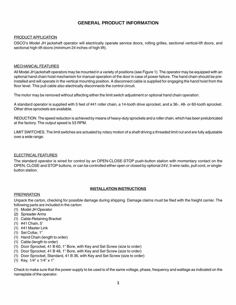
PRODUCT APPLICATION
OSCO’s Model JH jackshaft operator will electrically operate service doors, rolling grilles, sectional vertical-lift doors, andsectional high-lift doors (minimum 24 inches of high lift).
MECHANICAL FEATURES
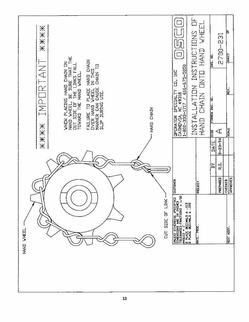
All Model JH jackshaft operators may be mounted in a variety of positions (see Figure 1). The operator may be equipped with anoptional hand chain hoist mechanism for manual operation of the door in case of power failure. The hand chain should be pre-installed and will operate in the vertical mounting position. A disconnect cable is supplied for engaging the hand hoist from thefloor level. This pull cable also electrically disconnects the control circuit.
The motor may be removed without affecting either the limit switch adjustment or optional hand chain operation.
A standard operator is supplied with 5 feet of #41 roller chain, a 14-tooth drive sprocket, and a 36-, 48- or 60-tooth sprocket.Other drive sprockets are available.
REDUCTION. The speed reduction is achieved by means of heavy-duty sprockets and a roller chain, which has been prelubricatedat the factory. The output speed is 53 RPM.
LIMIT SWITCHES. The limit switches are actuated by rotary motion of a shaft driving a threaded limit nut and are fully adjustableover a wide range.
ELECTRICAL FEATURES
The standard operator is wired for control by an OPEN-CLOSE-STOP push-button station with momentary contact on theOPEN, CLOSE and STOP buttons, or can be controlled either open or closed by optional 24V, 3-wire radio, pull cord, or single-button station.
INSTALLATION INSTRUCTIONS
PREPARATION
Unpack the carton, checking for possible damage during shipping. Damage claims must be filed with the freight carrier. Thefollowing parts are included in the carton:(1) Model JH Operator(2) Spreader Arms(1) Cable-Retaining Bracket(1) #41 Chain, 5’(1) #41 Master Link(1) Set Collar, 1”(1) Hand Chain (length to order)(1) Cable (length to order)(1) Door Sprocket, 41 B 60, 1” Bore, with Key and Set Screw (size to order)(1) Door Sprocket, 41 B 48, 1” Bore, with Key and Set Screw (size to order)(1) Door Sprocket, Standard, 41 B 36, with Key and Set Screw (size to order)(1) Key, 1/4” x 1/4” x 1”
Check to make sure that the power supply to be used is of the same voltage, phase, frequency and wattage as indicated on thenameplate of the operator.
1

2
LEFT-HAND INSTALLATION RIGHT-HAND INSTALLATION
FIGURE 1
FIGURE 2 INSTRUCTIONS FOR ATTACHMENT OFSPREADER ARM AND DOOR SPROCKET
SHAFT SPROCKET
DOORSHAFT
ROLLER CHAINAND
MASTER LINK
DRIVE SPROCKET JH OPERATORDRIVE SHAFT
SHAFTCOLLAR
SPREADER ARMASSEMBLY
SHAFT COLLAR1. Remove drive sprocket from JH operator drive
shaft.
2. Slide proper door shaft sprocket onto doorshaft, with key inserted into key way.
3. Slide spreader arm assembly onto the doorshaft.
4. Make any necessary adjustments in spreaderarm so lower end will slide onto operator driveshaft.
5. Slide drive sprocket onto drive shaft and tightenset screw securely.
6. Now position door shaft sprocket so it isexactly in line with the drive sprocket andtighten set screw securely.
7. Slide 1” shaft collar onto door shaft and tighten.
8. Place roller chain around sprockets and attachmaster link.
9. Attach wall retainer bracket onto wall forsecuring disconnect cable.
KEY

3
FIGURE 3 - OPERATOR MOUNTING
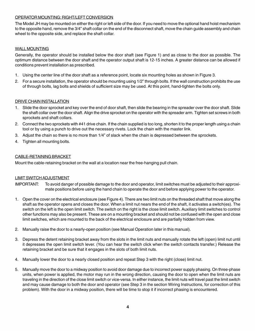
OPERATOR MOUNTING: RIGHT/LEFT CONVERSION
The Model JH may be mounted on either the right or left side of the door. If you need to move the optional hand hoist mechanismto the opposite hand, remove the 3/4” shaft collar on the end of the disconnect shaft, move the chain guide assembly and chainwheel to the opposite side, and replace the shaft collar.
WALL MOUNTING
Generally, the operator should be installed below the door shaft (see Figure 1) and as close to the door as possible. Theoptimum distance between the door shaft and the operator output shaft is 12-15 inches. A greater distance can be allowed ifconditions prevent installation as prescribed.
1. Using the center line of the door shaft as a reference point, locate six mounting holes as shown in Figure 3.
2. For a secure installation, the operator should be mounting using 1/2” through bolts. If the wall construction prohibits the useof through bolts, lag bolts and shields of sufficient size may be used. At this point, hand-tighten the bolts only.
DRIVE CHAIN INSTALLATION
1. Slide the door sprocket and key over the end of door shaft, then slide the bearing in the spreader over the door shaft. Slidethe shaft collar over the door shaft. Align the drive sprocket on the operator with the spreader arm. Tighten set screws in bothsprockets and shaft collars.
2. Connect the two sprockets with #41 drive chain. If the chain supplied is too long, shorten it to the proper length using a chaintool or by using a punch to drive out the necessary rivets. Lock the chain with the master link.
3. Adjust the chain so there is no more than 1/4” of slack when the chain is depressed between the sprockets.
4. Tighten all mounting bolts.
CABLE-RETAINING BRACKET
Mount the cable-retaining bracket on the wall at a location near the free-hanging pull chain.
LIMIT SWITCH ADJUSTMENT
IMPORTANT: To avoid danger of possible damage to the door and operator, limit switches must be adjusted to their approxi-mate positions before using the hand chain to operate the door and before applying power to the operator.
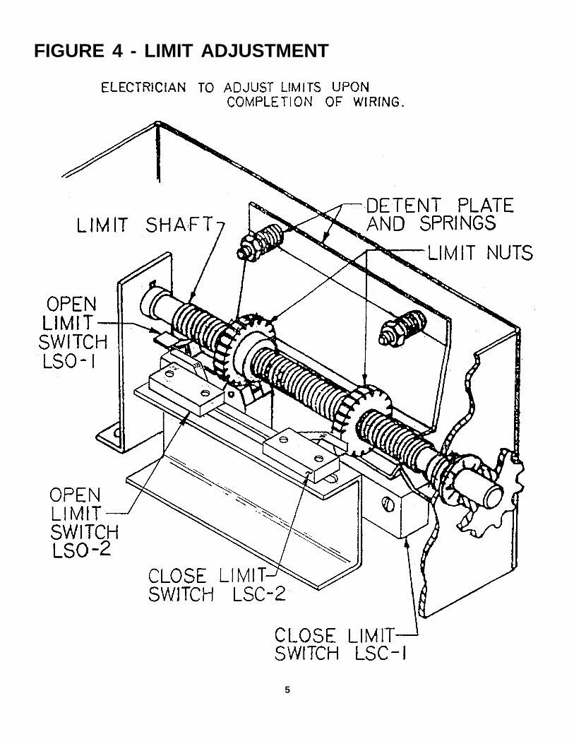
1. Open the cover on the electrical enclosure (see Figure 4). There are two limit nuts on the threaded shaft that move along theshaft as the operator opens and closes the door. When a limit nut nears the end of the shaft, it activates a switch(es). Theswitch on the left is the open limit switch. The switch on the right is the close limit switch. Auxiliary limit switches to controlother functions may also be present. These are on a mounting bracket and should not be confused with the open and closelimit switches, which are mounted to the back of the electrical enclosure and are partially hidden from view.
2. Manually raise the door to a nearly-open position (see Manual Operation later in this manual).
3. Depress the detent retaining bracket away from the slots in the limit nuts and manually rotate the left (open) limit nut untilit depresses the open limit switch lever. (You can hear the switch click when the switch contacts transfer.) Release theretaining bracket and be sure that it engages in the slots of both limit nuts.
4. Manually lower the door to a nearly closed position and repeat Step 3 with the right (close) limit nut.
5. Manually move the door to a midway position to avoid door damage due to incorrect power supply phasing. On three-phaseunits, when power is applied, the motor may run in the wrong direction, causing the door to open when the limit nuts aretraveling in the direction of the close limit switch or vice-versa. In either instance, the limit nuts will travel past the limit switchand may cause damage to both the door and operator (see Step 3 in the section Wiring Instructions, for correction of thisproblem). With the door in a midway position, there will be time to stop it if incorrect phasing is encountered.
4
5
FIGURE 4 - LIMIT ADJUSTMENT
6
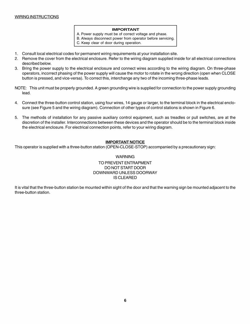
WIRING INSTRUCTIONS
1. Consult local electrical codes for permanent wiring requirements at your installation site.2. Remove the cover from the electrical enclosure. Refer to the wiring diagram supplied inside for all electrical connections
described below.3. Bring the power supply to the electrical enclosure and connect wires according to the wiring diagram. On three-phase
operators, incorrect phasing of the power supply will cause the motor to rotate in the wrong direction (open when CLOSEbutton is pressed, and vice-versa). To correct this, interchange any two of the incoming three-phase leads.
NOTE: This unit must be properly grounded. A green grounding wire is supplied for connection to the power supply groundinglead.
4. Connect the three-button control station, using four wires, 14 gauge or larger, to the terminal block in the electrical enclo-sure (see Figure 5 and the wiring diagram). Connection of other types of control stations is shown in Figure 6.
5. The methods of installation for any passive auxiliary control equipment, such as treadles or pull switches, are at thediscretion of the installer. Interconnections between these devices and the operator should be to the terminal block insidethe electrical enclosure. For electrical connection points, refer to your wiring diagram.
IMPORTANT NOTICEThis operator is supplied with a three-button station (OPEN-CLOSE-STOP) accompanied by a precautionary sign:
WARNING
TO PREVENT ENTRAPMENTDO NOT START DOOR
DOWNWARD UNLESS DOORWAYIS CLEARED
It is vital that the three-button station be mounted within sight of the door and that the warning sign be mounted adjacent to thethree-button station.
IMPORTANTA. Power supply must be of correct voltage and phase.B. Always disconnect power from operator before servicing.C. Keep clear of door during operation.
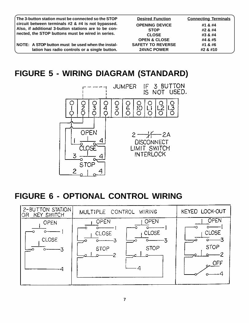
The 3-button station must be connected so the STOPcircuit between terminals #2 & #4 is not bypassed.Also, if additional 3-button stations are to be con-nected, the STOP buttons must be wired in series.
NOTE: A STOP button must be used when the instal-lation has radio controls or a single button.
Desired Function Connecting Terminals
OPENING DEVICE #1 & #4STOP #2 & #4
CLOSE #3 & #4OPEN & CLOSE #4 & #5
SAFETY TO REVERSE #1 & #624VAC POWER #2 & #10
7
FIGURE 5 - WIRING DIAGRAM (STANDARD)
FIGURE 6 - OPTIONAL CONTROL WIRING
8
CONNECTION OF AN EXTERNAL INTERLOCK DEVICE
Circuitry is provided on all standard Model JH operators for the connection of a two-wire external interlock device that, whenactuated, prevents the door from being electrically operated. This should be wired into the terminal block in the electricalenclosure (see Figure 5 and the wiring diagram).
NON-STANDARD WIRING
If your operator is supplied with a non-standard wiring type (see Wiring Specifications), for your particular application, refer toyour wiring diagram for connection of all control equipment. If the wiring diagram is missing or has been lost, call the factory forreplacement. Do not install any wiring or attempt to run this operator without consulting the wiring diagram.
OPERATING INSTRUCTIONSELECTRICAL OPERATION
The Model JH is designed to provide years of trouble-free electrical operation of your door. The door can be operated by meansof the three-button control station or by other controls, when provided. If a reversing edge is wired into the operator, the door willreverse to the fully-open position when it hits an obstruction during downward travel.
The motor is protected by an automatic-reset thermal overload protector which will trip when the motor temperature is too hot orwhen the motor is overloaded. DO NOT ATTEMPT TO BYPASS THIS UNIT! The overload protector will trip only under abnormalconditions. An out-of-balance door or one that is binding in the tracks can produce such a condition. An incorrect installationmay also cause such a problem. If a protector continues to trip, consult a serviceman or the factory.
MANUAL OPERATION (optional)
The Model JH may be used to operate the door manually if necessary. An electrical interlock will disable the motor when theoperator is used in such a fashion. To manually operate the door:
1. Pull the small disconnect cable to disengage the motor. This cable may be locked in position by slipping the end throughthe cable-retaining bracket mounted on the wall.
2. Operate the door by hand.3. The cable must be released from the retaining bracket before the door will operate electrically.
SERVICE AND TROUBLESHOOTING
A properly-installed Model JH will operate for many years with minimal service and maintenance. It is important to note, however,that an improperly-balance or defective door can severely reduce the life of the operator. The door should be checked andlubricated periodically as recommended by the manufacturer. All bearings are oil impregnated or lifetime sealed anti-frictionbearings. The motor is factory lubricated and requires no additional lubrication.
A few drops of oil should be applied periodically to the moving parts of the manual disconnect mechanisms.
Should electrical malfunction occur, consult the Troubleshooting Chart on the following page.

9
TROUBLESHOOTING CHART
SYMPTOM POSSIBLE CAUSE REMEDYMotor does not run when OPEN or 1. Building fuse blown or circuit 1. Replace fuse or reset breakerCLOSE button is pressed. breaker tripped. and check for cause.
2. Overload protector tripped. 2. Reset and check for cause.
3. Disconnect lever in position for 3. Return lever to position formanual operations. electrical operation.
4. Check transformer secondaryvoltage. Check contactor coilsfor possible burnout. Checklimit switches and interlockswitch. Inspect control stationand all field wiring.
Door closes when OPEN button 1. Three-phase power supply is 1. Interchange any twopressed and limit switches do connected out of phase. incoming power supply leads.not function.
2. Operator is mounted upside-down. 2. Consult factory.
Operator does not shut off at 1. Limit nuts not properly adjusted. 1. See “Limit Switchfully-opened or fully-closed position. Adjustment.”
2. Limit drive chain broken orinoperative. 2. Replace chain, check
mechanism.3. Limit switch damaged.
3. Check limit switch operationand replace if necessary.
10
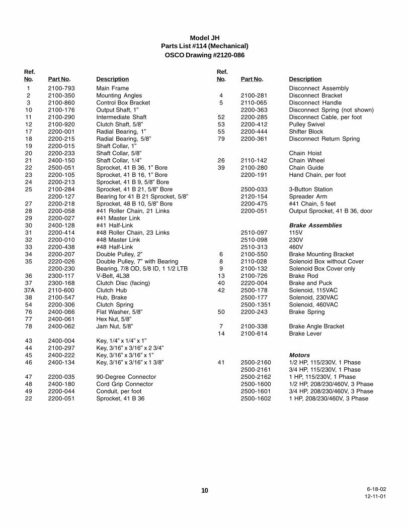
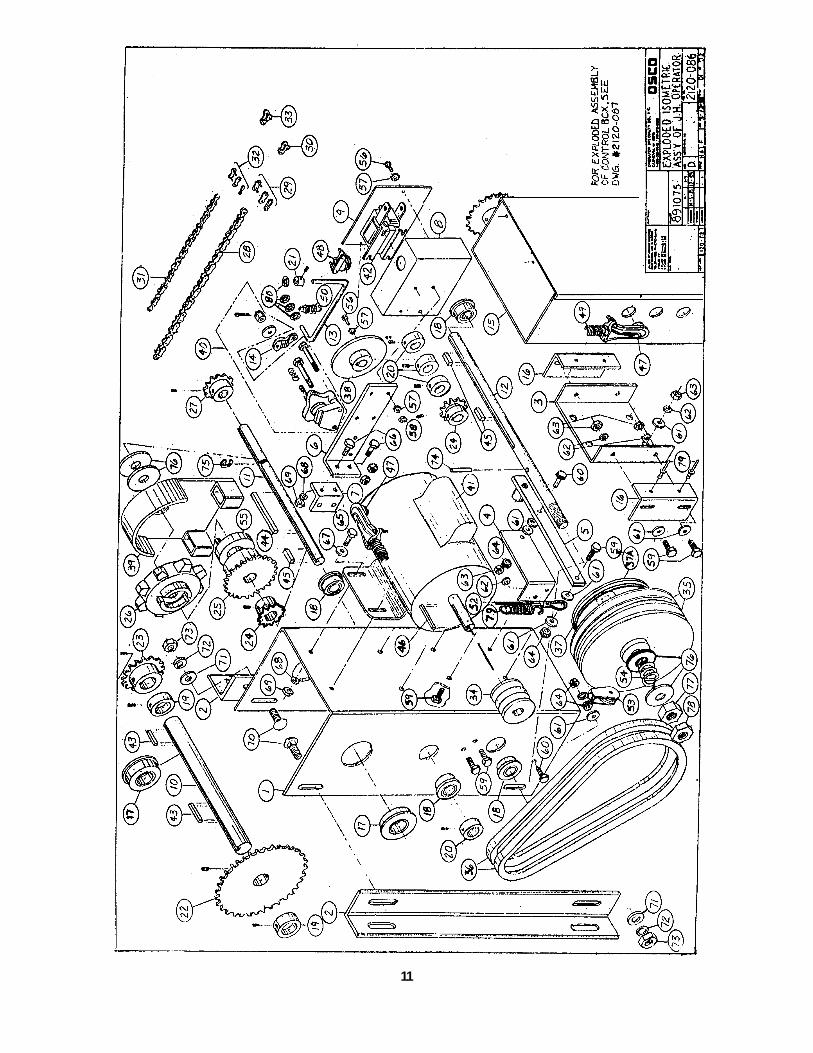
Model JHParts List #114 (Mechanical)
OSCO Drawing #2120-086
Ref.No. Part No. Description
1 2100-793 Main Frame2 2100-350 Mounting Angles3 2100-860 Control Box Bracket
10 2100-176 Output Shaft, 1”11 2100-290 Intermediate Shaft12 2100-920 Clutch Shaft, 5/8”17 2200-001 Radial Bearing, 1”18 2200-215 Radial Bearing, 5/8”19 2200-015 Shaft Collar, 1”20 2200-233 Shaft Collar, 5/8”21 2400-150 Shaft Collar, 1/4”22 2500-051 Sprocket, 41 B 36, 1” Bore23 2200-105 Sprocket, 41 B 16, 1” Bore24 2200-213 Sprocket, 41 B 9, 5/8” Bore25 2100-284 Sprocket, 41 B 21, 5/8” Bore
2200-127 Bearing for 41 B 21 Sprocket, 5/8”27 2200-218 Sprocket, 48 B 10, 5/8” Bore28 2200-058 #41 Roller Chain, 21 Links29 2200-027 #41 Master Link30 2400-128 #41 Half-Link31 2200-414 #48 Roller Chain, 23 Links32 2200-010 #48 Master Link33 2200-438 #48 Half-Link34 2200-207 Double Pulley, 2”35 2220-026 Double Pulley, 7” with Bearing
2200-230 Bearing, 7/8 OD, 5/8 ID, 1 1/2 LTB36 2300-117 V-Belt, 4L3837 2300-168 Clutch Disc (facing)37A 2110-600 Clutch Hub38 2100-547 Hub, Brake54 2200-306 Clutch Spring76 2400-066 Flat Washer, 5/8”77 2400-061 Hex Nut, 5/8”78 2400-062 Jam Nut, 5/8”
43 2400-004 Key, 1/4” x 1/4” x 1”44 2100-297 Key, 3/16” x 3/16” x 2 3/4”45 2400-222 Key, 3/16” x 3/16” x 1”46 2400-134 Key, 3/16” x 3/16” x 1 3/8”
47 2200-035 90-Degree Connector48 2400-180 Cord Grip Connector49 2200-044 Conduit, per foot22 2200-051 Sprocket, 41 B 36
Ref.No. Part No. Description
Disconnect Assembly4 2100-281 Disconnect Bracket5 2110-065 Disconnect Handle
2200-363 Disconnect Spring (not shown)52 2200-285 Disconnect Cable, per foot53 2200-412 Pulley Swivel55 2200-444 Shifter Block79 2200-361 Disconnect Return Spring
Chain Hoist26 2110-142 Chain Wheel39 2100-280 Chain Guide
2200-191 Hand Chain, per foot
2500-033 3-Button Station2120-154 Spreader Arm2200-475 #41 Chain, 5 feet2200-051 Output Sprocket, 41 B 36, door
Brake Assemblies2510-097 115V2510-098 230V2510-313 460V
6 2100-550 Brake Mounting Bracket8 2110-028 Solenoid Box without Cover9 2100-132 Solenoid Box Cover only
13 2100-726 Brake Rod40 2220-004 Brake and Puck42 2500-178 Solenoid, 115VAC
2500-177 Solenoid, 230VAC2500-1351 Solenoid, 460VAC
50 2200-243 Brake Spring
7 2100-338 Brake Angle Bracket14 2100-614 Brake Lever
Motors41 2500-2160 1/2 HP, 115/230V, 1 Phase
2500-2161 3/4 HP, 115/230V, 1 Phase2500-2162 1 HP, 115/230V, 1 Phase2500-1600 1/2 HP, 208/230/460V, 3 Phase2500-1601 3/4 HP, 208/230/460V, 3 Phase2500-1602 1 HP, 208/230/460V, 3 Phase
12-11-016-18-02
11
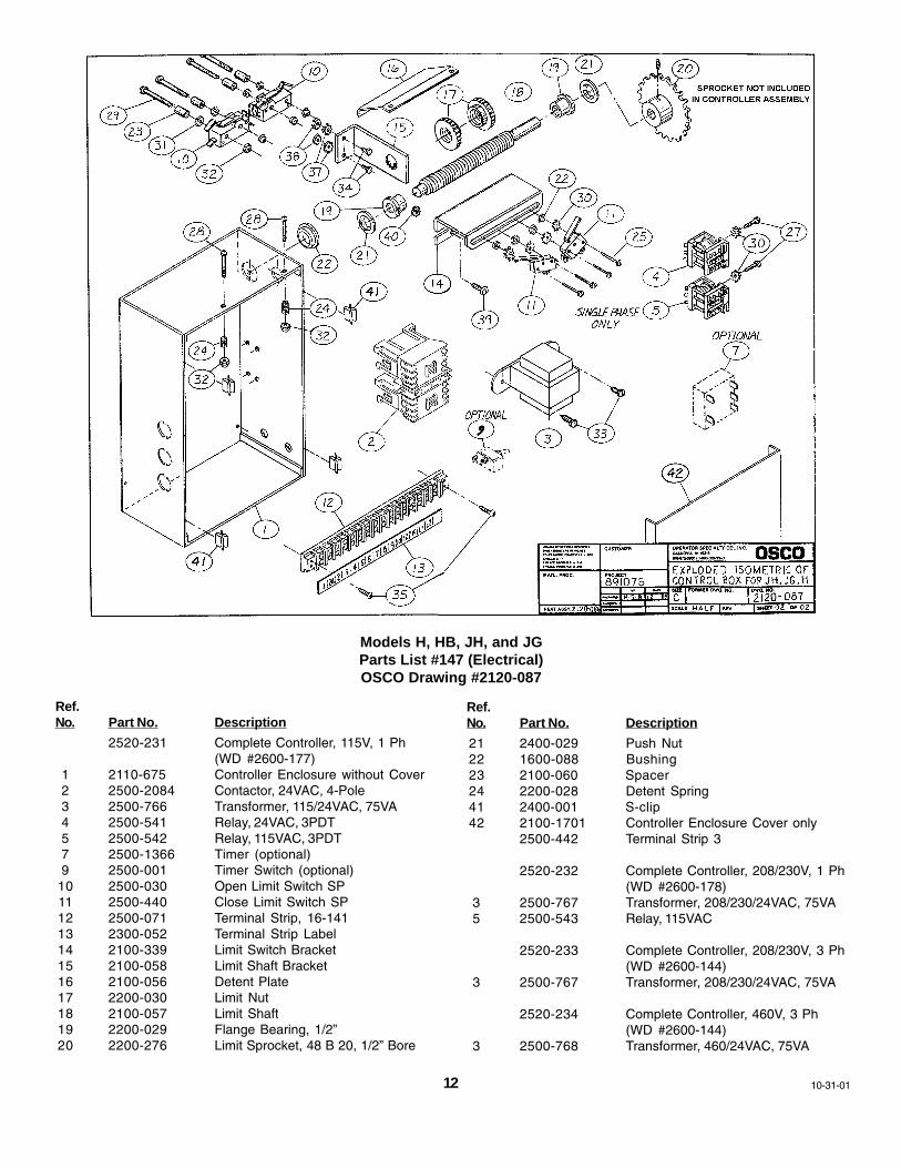
Models H, HB, JH, and JGParts List #147 (Electrical)OSCO Drawing #2120-087
Ref.No. Part No. Description
2520-231 Complete Controller, 115V, 1 Ph(WD #2600-177)
1 2110-675 Controller Enclosure without Cover2 2500-2084 Contactor, 24VAC, 4-Pole3 2500-766 Transformer, 115/24VAC, 75VA4 2500-541 Relay, 24VAC, 3PDT5 2500-542 Relay, 115VAC, 3PDT7 2500-1366 Timer (optional)9 2500-001 Timer Switch (optional)
10 2500-030 Open Limit Switch SP11 2500-440 Close Limit Switch SP12 2500-071 Terminal Strip, 16-14113 2300-052 Terminal Strip Label14 2100-339 Limit Switch Bracket15 2100-058 Limit Shaft Bracket16 2100-056 Detent Plate17 2200-030 Limit Nut18 2100-057 Limit Shaft19 2200-029 Flange Bearing, 1/2”20 2200-276 Limit Sprocket, 48 B 20, 1/2” Bore
Ref.No. Part No. Description
21 2400-029 Push Nut22 1600-088 Bushing23 2100-060 Spacer24 2200-028 Detent Spring41 2400-001 S-clip42 2100-1701 Controller Enclosure Cover only
2500-442 Terminal Strip 3
2520-232 Complete Controller, 208/230V, 1 Ph(WD #2600-178)
3 2500-767 Transformer, 208/230/24VAC, 75VA5 2500-543 Relay, 115VAC
2520-233 Complete Controller, 208/230V, 3 Ph(WD #2600-144)
3 2500-767 Transformer, 208/230/24VAC, 75VA
2520-234 Complete Controller, 460V, 3 Ph(WD #2600-144)
3 2500-768 Transformer, 460/24VAC, 75VA
12 10-31-01
13
14
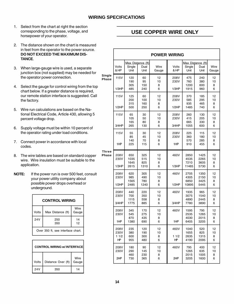
1. Select from the chart at right the sectioncorresponding to the phase, voltage, andhorsepower of your operator.
2. The distance shown on the chart is measuredin feet from the operator to the power source.DO NOT EXCEED THE MAXIMUM DIS-TANCE.
3. When large-gauge wire is used, a separatejunction box (not supplied) may be needed forthe operator power connection.
4. Select the gauge for control wiring from the topchart below. If a greater distance is required,our remote station interface is suggested. Callthe factory.
5. Wire run calculations are based on the Na-tional Electrical Code, Article 430, allowing 5percent voltage drop.
6. Supply voltage must be within 10 percent ofthe operator rating under load conditions.
7. Connect power in accordance with localcodes.
8. The wire tables are based on standard copperwire. Wire insulation must be suitable to theapplication.
NOTE: If the power run is over 500 feet, consultyour power utility company aboutpossible power drops overhead orunderground.
WIRING SPECIFICATIONS
USE COPPER WIRE ONLY
POWER WIRING
Max Distance (ft) Max Distance (ft)Volts Single Dual Wire Volts Single Dual Wire& HP Unit Unit Gauge & HP Unit Unit Gauge
115V 120 60 12 208V 475 240 12190 95 10 230V 760 380 10305 150 8 1200 600 8
1/3HP 485 240 6 1/3HP 1915 960 6
115V 125 60 12 208V 370 185 12200 100 10 230V 585 295 10315 160 8 935 465 8
1/2HP 500 250 6 1/2HP 1485 740 6
115V 65 30 12 208V 260 130 12105 50 10 230V 415 205 10165 80 8 665 330 8
3/4HP 265 130 6 3/4HP 1055 600 6
115V 55 30 12 208V 225 115 1285 45 10 230V 360 180 10
140 70 8 570 285 81HP 225 115 6 1HP 910 455 6
208V 650 325 12 460V 2850 1425 12230V 1035 515 10 4535 2265 10
1645 825 8 7210 3605 81/3HP 2615 1310 6 1/3HP 11465 5730 6
208V 620 305 12 460V 2705 1350 12230V 985 490 10 4305 2150 10
1565 780 8 6850 3425 81/2HP 2485 1240 6 1/2HP 10895 5445 6
208V 440 220 12 460V 1935 965 12230V 700 350 10 3075 1540 10
1115 558 8 4890 2445 83/4HP 1775 885 6 3/4HP 7780 3890 6
208V 345 170 12 460V 1595 795 12230V 545 275 10 2535 1265 10
870 435 8 4030 2015 81HP 1380 690 6 1HP 6405 3205 6
208V 235 120 12 460V 1040 520 12230V 380 190 10 1655 825 101 1/2 600 300 8 1 1/2 2635 1315 8HP 955 480 6 HP 4190 2095 6
208V 180 90 12 460V 795 400 12230V 290 145 10 1265 635 10
460 230 8 2015 1005 82HP 730 365 6 2HP 3205 1600 6
SinglePhase
ThreePhase
CONTROL WIRING
WireVolts Max Distance (ft) Gauge
24V 250 14350 12
Over 350 ft, see interface chart.
CONTROL WIRING w/ INTERFACE
WireVolts Distance Over (ft) Gauge
24V 350 14