MODEL F3 F5 INSTALLATION MANUALbostonheatingsupply.com/Riello/Riello F3 - F5 installation.pdf ·...
21
MODEL F3 & F5 INSTALLATION MANUAL RIELLO 40 SERIES RESIDENTIAL OIL BURNERS NOTE: The settings in this manual are for retrofit applications. If this burner is being installed on a packaged unit (burner comes with the boiler or furnace), then follow the settings on the OEM page, as settings may differ. Burner is set for a single line system. C6501010 STANDARD F3-5 MANUAL Rev. 3 - 08/03/2005 1
Transcript of MODEL F3 F5 INSTALLATION MANUALbostonheatingsupply.com/Riello/Riello F3 - F5 installation.pdf ·...

MODEL F3 & F5INSTALLATION
MANUAL
RIELLO 40SERIES
RESIDENTIAL
OIL BURNERS
NOTE: The settings in this manual are for retrofit applications. If this burner is being installed on a packagedunit (burner comes with the boiler or furnace), then follow the settings on the OEM page, as settings maydiffer. Burner is set for a single line system.
C6501010 STANDARD F3-5 MANUAL Rev. 3 - 08/03/2005 1

TABLE OF CONTECT
TECHNICAL DATA - Model F3 ..................................................................................... 3TECHNICAL DATA - Model F5 ..................................................................................... 4
OIL BURNER COMPONENT IDENTIFICATION ......................................................... 5
Burner Components ....................................................................................................... 5Serial Number Identification .......................................................................................... 5
INITIAL SET-UP .............................................................................................................. 5ASSEMBLY OF AIR TUBE TO BURNER CHASSIS .................................................... 6
MOIJNTING BURNER TO BOILER OR FURNACE ................................................ 6 - 8
Method 1-Universal Mounting Flange ........................................................................... 7Method 2-Semi-flange Collar ........................................................................................ 8Method 3-Pedestal Mount .............................................................................................. 8
ELECTRICAL CONNECTIONS ...................................................................................... 8
APPLICATION FIELD WIR1NG ..................................................................................... 9
NOZZLE PLACEMENT ................................................................................................. 10INSERTION / REMOVAL OF DRAWER ASSEMBLY ............................................... 10
ELECTRODE SETTING ................................................................................................. 11TURBULATOR SETT1NG ............................................................................................. 11
OIL LINE CONNECTIONS ..................................................................................... 11 - 13
Single Line (Gravity Feed) .......................................................................................... 12Two Line (Lift System) ......................................................................................... 12 - 13
PUMP PURGE .......................................................................................................... 13 - 14
Single Line (Gravity System) ...................................................................................... 13Two Line (Lift System) ................................................................................................ 14
SETTING THE AIR ADJUSTMENT PLATE ................................................................ 14
BURNER ADJUSTMENT TABLES .............................................................................. 15
AMULET INSTALLATION INSTRUCTIONS ............................................................. 16INSTALLATION PRECAUTIONS ................................................................................ 17
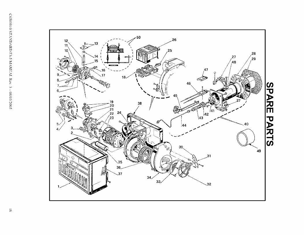
EXPLODED SPARE PARTS LIST ................................................................................ 18
SPARE PARTS LIST ...................................................................................................... 19
PACKAGE LIST
Your Riello 40 burner should include the following parts. Please check to make sure all parts are present before
beginning the installation_
QTY. DESCRIPTION (parts bag)
_
2-4-
2-
l-
l-
l-l-
l-
Mounting flange bolts (short)
Semi-flange bolts (long)Nuts
Chrome nuts
Oil pump connector (supply)
Oil pump connector (return)
Female ¼" NPT adapterMale 3/8" NPT adapter
2.5 mm Allen key* OEM burners shipped with combustion head mounted
QTY. DESCRIPTION (carton)
_
1-2-
1-
1-
1-
Burner chassis with cover
Universal Mounting FlangeSemi- flanges
Mounting gasketInstallation Manual
By-pass plug
* (Separate carton)1 - Combustion Head
C6501010 STANDARD F3-5 MANUAL Rev. 3 - 08/03/2005 2

RIELLO 40 F3 TECHNICAL DATA
TA
1
B,
0
1111111111111¢
E
E1F=
DIMENSIONS
Inches 8 15/32 9 59/64 6 15/32
1rim 215 252 164
El: 10-inch long (254iron) tubes are also available.
3 1/2 6 8 29/32
89 152 226
SPECIFICATIONSFUEL:
FIRING RATE:
EFFECTIVE OUTPUT:
VOLTAGE (Single Phase):
ABSORBED ELECTRICAL POWER:
MOTOR (rated):
CAPACITOR:
PUWIP PRESSURE:
PRIMARY CONTROL:
IGNITION TRANSFORMER:
I, No. 2 Fuel Oil-!
-0.50 to 0.95 US GPH
', 70,000 to 133,000 BTU/h
I 120V 60Hz (+ 10% - 15%)
-_-564 Watts', 3250 rpm Run Current 2.2 AMP
-!
_" 12.5 Microl_arads
', 130 to 200 psigI RIELLO 530 SE/C
' 8kV 16mAI
MOUNTING FLANGE DIMENSIONS
Inch 1 1/4 1/4 7/16 2 3/16
in_n 32 6 11 56
60°_ _B
! ', IE/ . i _k \ DoE
"...... • ....... __.......... 1"ii " co
7 _19 _ "I Q_mm
C6501010 STANDARD F3-5 MANUAL Rev. 3 - 08/03/2005 3
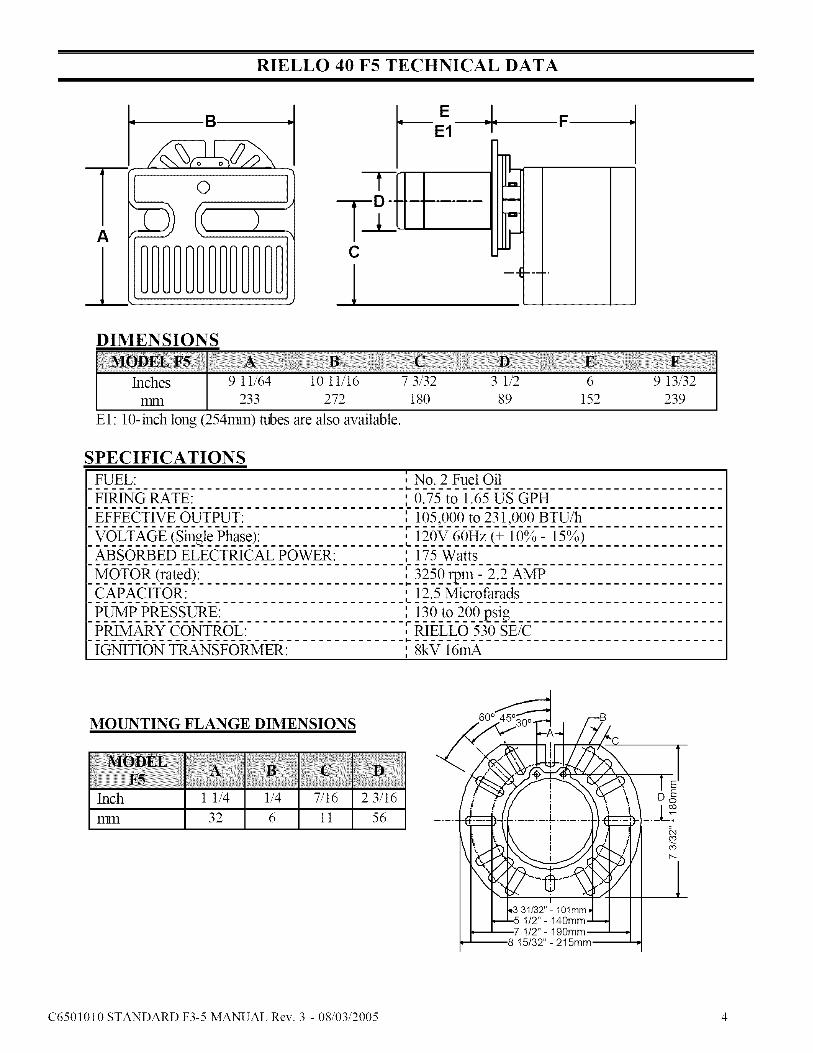
RIELLO 40 F5 TECHNICAL DATA
A
l
a.
©B
C
1
EF
E1 P9
DIMENSIONS
Inches 9 11/64 10 11/16 7 3/32 3 1/2 6 9 13/32
1rim 233 272 180 89 152 239
El: 10-inch long (254mm) tubes are also available.
SPECIFICATIONSFUEL:
FIRING RATE:
EFFECTIVE OUTPUT:
VOLTAGE (Single Phase):ABSORBED ELECTRICAL POWER:
MOTOR (rated):
CAPACITOR:
PUWfP PRESSURE:
PRIMARY CONTROL:
IGNITION TRANSFORMER:
i
, No. 2 Fuel Oil-i.--
', 0.75 to 1.65 US GPH
', 105,000 to 231,000 BTU/h-1
, 120V 60Hz (+ 10% - 15%)-L-
' 175 WattsI
I
, 3250 rpm - 2.2 AMP
_i. 12.5 Microfiarads
I 130 to 200 psig-I RIELLO 530 SE/C
' 8kV 16mAI
C6501010 STANDARD F3-5 MANUAL Rev. 3 - 08/03/2005 4

OIL BURNER COMPONENTS IDENTIFICATIONRIELLO 40 SERIES
Q-
G-I
F3 & F5 BURNER COMPONENTS
1. Lockout indicator lamp and reset button
2. Primary control
3. Primary control sub-base4. Pump pressure regulator5. Motor
6. Air adjustment fixing screws
7. Hydraulic air shutter
8. Capacitor
9. Hydraulic Jack (optional)10. Combustion Head
11. Semi Flange
12. Turbulator adjustment screw13. Air tube cover
14. Coil
15. Vacuum gauge port16. Pressure gauge and bleeder port
17. Return fuel line port
18. Supply fuel line port
19. Capillary tube
20. Mounting flange with gasket
SERIAL NUMBER IDENTIFICATION
The Riello 15 character serial number, exmnple, 99 A 8511111 00025, is identified as follows:
99 = last two digits of the year of manufacture; A = BI-week of manufacture; 8511111 = burner product code;00025 = increment of 1 for each burner produced - specific to product code - reset to zero each January 1_t.
(99) (A) (811111) (00025)
Ye ofm uf c elIBIweekofm uf c eIBurnerprod c codeIIIncremen IINITIAL SET-UP
A) Remove burner and air tube from cartons. Check parts list (inside cover) to ensure all parts are present.
B) Remove burner cover by loosing the three screws securing it. Remove control box and air tube cover (seepage 8).
C) Remove drawer assembly from air tube, insert nozzle and set Turbulator adjustment for specific inputrequired (see pages 8 & 9), then set aside.
D) Mount air tube to burner chassis (see next page).
C6501010 STANDARD F3-5 MANUAL Rev. 3 - 08/03/2005 5

ASSEMBLY OF AIR TUBE TO BURNER CHASSIS
The air tube and drawer assembly are shipped in a carton separate from the burner chassis. Choose the properair tube length to obtain the tube insertion for the specific installation.
A) Remove the AIR TU33E and BUNNER CHASSIS from their respective cartons.
B) Remove the DRAWER ASSEMBLY (1) from inside the MR TUBE by loosening the screw (2). Carefully
pull the DRAWER ASSEMBLY out of the MR TUBE, install the required nozzle (see page 8) and setaside.
C) Remove the two BOLTS (3) from FRONT PLATE (4) of the BURNER CHASSIS. Align the two holes on
the AIR TUBE HOLD1NG PATE (5) with the two holes on the BURNER CHASSIS FRONT PLATE with
the BOLTS (3) removed. Replace the BOLTS and fingers tighten only. Re-install DRAWER ASSEMBLYinto AIR TU33E. Tighten SCREW (2) securely (see page 8).
D) Tighten the two bolts (3) securely.
)!Tl ..............................
I
I
|
MOUNTING THE BURNER TO THE BOILER OR FURNACE
There are three possible methods to mount the burner, depending on the individual application. These are:
1) Universal flange bolted to BoilerFFumace unit.
2) Semi-flange collar bolted to BoilerFFurnace unit.
3) Universal flange mounted to optional Pedestal mount, where flange mounting direct to appliance is not
possible. Pedestal kit must be ordered separately.
C6501010 STANDARD F3-5 MANUAL Rev. 3 - 08/03/2005 6

METHOD 1 - UNIVERSAL MOUNTING FLANGE
A) Insert the two BOLTS (1) into the UNIVERSAL MOUWHNG FLANGE (10) from the flat side, ensuringthe bolt heads are flush with the flat surface. Secure in place using two special CHROME NUTS (2)provided.
COMBUSTIONCHAMBER
.J
---,,b
DRYBASE
BOILER
B) Position the MOU2qT1NG GASKET (3) between the flat surface of the UNIVERSAL MOU2qT1NG
FLANGE (10) and the appliance. Line up the holes in the UNIVERSAL MOUNTING FLANGE with the
STUDS (4) on the appliance mounting plate and securely bolt the UNIVERSAL MOU2qT1NG FLANGE tothe plate.
C) Secure the two semi-flanges of the ADJUSTABLE COLLAR (9) to the AIR TU'I3E using the two longBOLTS (6). Be sure that the ADJUSTABLE (Z)LLAR (9) is properly positioned so the outside edge of the
END CONE will be at least */4 inch (6.51ran) back from the inside wall of the refractory of the combustionchamber (see dimension B above). The measured length (A) is to include MOU2qT1NG GASKET andFLANGE, if used.
D) The burner may now be attached to the heating unit by insetting the AIR TU'I3E through the BUNNERACCESS HOLE (8) and into the appliance, making sure the BOLTS (1) line up with the two HOLES (5) in
the ADJUSTABLE COLLAR (9). Secure the burner in place using two NUTS (7).A visual verification of the air tube insertion into the combustion chmnber of the heating unit is suggested.Dimension B should be at least */4"(see drawing).
NOTE: A suggested method for creating mounting bolt holes in the mounting gasket: Hold the gasket against
the appliance mounting bolts using the mounting flange for proper positioning. Lightly tap the flange with ahalraner to form the holes.
C6501010 STANDARD F3-5 MANUAL Rev. 3 - 08/03/2005 7

METHOD 2 - SEMI-FLANGE COLLAR
A) Follow item C from METHOD 1.
B) Align the air tube and attached adjustable collar so air tube is centered in the bumer access hole of the
boiler/furnace unit. Mark the center of the two holes in the ADJUSTABLE COLLAR on to the front plate ofthe heating unit. Then drill */4inch (6.5ram) holes through the fror_ plate of the unit, using marks as a guide.
C) Install two short BOLTS (1) through the front plate of the heating unit from the inside, and secure on the
outside using the two special CHROME NUTS (2).D) Follow item D from METHOD 1.
METHOD 3 - PEDESTAL MOUNT
Secure the MOU2qTING FLANGE to MOU2qT1NG PEDESTAL using the hardware provided with the pedestal.Secure burner to MOU2qT1NG FLANGE as in METHOD 1, item A, C and D.
NOTE: It is suggested that the pedestal be anchored in position on the floor by installing brackets over the
)edestal tube and securing brackets to the floor.
WARNING: WHEN THE COMBUSTION CHAMBER IS LINED WITH A REFRACTORY
MATERIAL, IT IS IMPERATIVE THAT THE END CONE NOT PROTRUDE INTO THE
CHAMBER AREA, AS EXCESSIVE HEAT AT BURNER SHUT DOWN WILL DAMAGE THEEND CONE.
ELECTRICAL CONNECTIONS
It is advisable to leave the control box offthe sub-base while completing the electrical connection to the burner.
1) Wire access hole (Use BX electrical
connector)
2) Earth ground conductor tetlninal (Greenwire)
3) Hot conductor terminal (Black wire)
4) Neutral conductor terminal (White wire)
5) Strain relief clamp
WARNING: The hot (black) wire must beconnected to the L terminal and the neutral
(white) wire must be connected to the Nterminal or the primary safety control will
be damaged. Do not connect wither wire to
the terminal marked
The burner may be controlled using either a DIRECT L1NE VOLTAGE control circuit (120V AC 60 cycle) ORa LOW VOLTAGE control switching relay.
Using the appropriate diagram below, make elecNcal connections to bumer. All wiring must be done inaccordance with existing electrical codes, both national and local. When all electrical connections have beenmade, the control box may be put back in place on the sub-base.
WARNING: DO NOT activate burner until proper oil line connections have been made, or failure of thepump shaft seal may occur.
C6501010 STANDARD F3-5 MANUAL Rev. 3 - 08/03/2005 8

APPLICATION FIELD WIRING
DIRECT LINEVOLTAGE LOW VOLTAGE
DiI;I III
W_RED SUB
CAPACITOR
I(
REMOTE SENS1NG OF SAFETY LOCKOUT: The SAFETY SWITCH in the 530SE CONTROL BOX is
equipped with a contact allowing remote sensing of burner lockout. The electrical connection is made at
terminal 4 (-) on the SU33-BASE. Should lockout occur the 530SE CONTROL BOX will supply a power source
of 120Vac to the connection terminal. The maximum allowable current draw on this terminal (4) is 1 Amp.
WARNING: If a neutral or ground lead is attached to this terminal, the CONTROL BOX on
the burner will be damaged shouhl lockout occur.
C6501010 STANDARD F3-5 MANUAL Rev. 3 - 08/03/2005 9

NOZZLE PLACEMENT
A) Determine the proper firing rate for the boiler or furnace units, considering the specific application, and then
use the Burner Setup charts on page 15 to select the proper nozzle and pump pressure to obtain the required
input from the burner.B) Remove the NOZZLE ADAPTER (2) from the DRAWER
ASSEMBLY by loosening the SCREW (1).C) Insert the proper NOZZLE into the NOZZLE ADAPTER
and tighten securely (Do not over tighten).D) Replace adapter, with nozzle installed, into drawer
assembly and secure with screw (1).
INSTALLATION/REMOVAL OF DRAWER ASSEMBLY
Removal:
A) Loosen off oil delivery tube nut from pump.
B) Loosen SCREW (3), and then unplug CONTROL BOX (1) by carefully pulling it back and then up.C) Remove the AIR TUBE COVER PLATE (5) by loosening the retaining SCREW (4) (Two SCREWS -
Model F5).
D) Loosen SCREW (2), and then slide the complete drawer assembly out of the combustion head as shown.E) To insert drawer assembly, reverse the procedure in items A to D above.
C6501010 STANDARD F3-5 MANUAL Rev. 3 - 08/03/2005 10

ELECTRODE SETTING
IMPORTANT: THIS DIMENSIONS MUST BE OBSERVED AND VERIFIED.
t._l- .....; f'i';,
\ _x +1_'_'¢_--.,
.f"
-{-._k_.
/ 1_--5/32" - 4mm
rr ,:_.,.,! 1.4,-;":i÷__ •..liz s'I"tL%,q-"
nJ,,
• 1-, 14.-4. -.,L. I
I
'IL .......
.......................... t-.--.'-":--._., 13/64'
........................ .I '_', 5mm'%___L.
7" _--%. ['ml:--
.......................... .-.[ • °
I5/64'+ to 7/64" or 2 to2.5n'm_----_l
TURBULATOR SETTING
A) Loosen NUT (1), and then turn SCREW (2) until the INDEX MARKER (3) is aligned with the correct
index number as per the Burner Setup charts, or OEM specifications given with the appliance.B) Retighten the RETAINING NUT (1).
NOTE: OEM specifications take priority over retrofit
specifications shown in this manual.
MODEL F3 NOTE: Zero and four are scale indicators onlyFrom left to right the first line is 4 and the last line 0.
MODEL F5: Same as above, except, scale indicators are 0and 3.
OIL LINE CONNECTIONS
This burner is shipped with the oil pump set to operate cn a single line system. To operate on a two-line system the by-
pass plug must be installed.WARNING: Do not operate a single line system with the by-pass plug installed. Operating a single line system with the
by-pass plug installed will result in damage to the pump shaft seal.
NOTE: Pump pressure must be set at time of burner start-up. A pressure gauge is attached to the PRESSURE PORT (8)
for pressure readings. Two PIPE CONNECTORS (6) are supplied with the burner tbr connection to either a single ortwo-line system. Also supplied are two ADAPTORS (3), two tEmale 1/4" NPT, to adapt oil lines to burner pipe
connectors. All pump port threads are British Parallel Thread design. Direct connection of NPT threads to the pump willdamage fl_e pump body.
Riello manometers and vacuum gauges do not require any adapters, and can be satEly connected to the pump ports. An
NPT 0netric) adapter must be used when connecting other gauge models.
!
I
- ,i,., .,_'i_)_ Es'.
"-/ "'-_ _ €--_ J'4 _.
', . -'-m t'--r--*, i. ! II
C6501010 STANDARD F3-5 MANUAL Rev. 3 - 08/03/2005 11

SINGLE LINE (GRAVITY FEED SYSTEM)
A) The burner is shipped configured for use in single line applications. No changes to the oil pump are requiredfor use in single line applications.
NOTE: If the pump cover (1) is removed for any reason, be sure the O-ring (2), is properly seated in the pumpcover (1) before re-attaching the pump cover to the pump housing.
SINGLE LINE SYSTEM-PIPE LENGTHS
H 3/8" OD 1/2" OD
FT M FT M FT M
1.5 0.5 33 l0 65 20
3.0 1.0 65 20 130 40
5.0 1.5 130 40 260 80
6.5 2.0 195 60 325 100
B) Connect the pipe connector to the SUPPLY PORT(5)of the pump. Attach the NPT adapter to the pipe
connector. Attach the required piping to this pipe
adapter. Be sure that the plug in the RETURN PORT
(7) is tightened securely.
P
H o
NOTE: Do not exceed pipe lengths indicated inchart.
TWO LINE (LIFT SYSTEM)
2 LINE (LIFT) SYSTEM-PIPELENGTHS
H 3/8" OD 1/2" OD
FT M FT M FT M
0.0 0.0 ll5 35 330 100
1.5 0.5 100 30 330 100
3.0 1.0 80 25 330 100
5.0 1.5 65 20 295 90
6.5 2.0 50 15 230 70
9.5 3.0 25 8 100 30
A) Ifa two-line system is required, install the By-pass plugprovided. The by-pass plug is installed in the return pol_
of the pump. A 2.5-1rnn hexagonal key provided withthe by-pass plug is to be used to install the plug. DO
NOT use an inch size hexagonal key; damage to the by-
pass plug may result. When operating on a two-linesystem, supply and return lines should be the same
diameter and both should extend to the same depthinside the fuel tank. Be sure there are no air leaks or
blockages in the piping system. Any obstructions in the
return line will cause failure of the pump shaft seal. Do notexceed the pipe lengths indicated in the tables on page 10.
NOTE: Do not exceed pipe lengths indicated inchart.
C6501010 STANDARD F3-5 MANUAL Rev. 3 - 08/03/2005 12

2,0.jn.s.t.a.!L..m..e..by:_.a..s.s._J.u.g;,
1) Remove the return plug (7)2) Install the by-pass plug (4) using the 2.5 1ran hexagonal key
B) Attach the two PIPE CONNECTORS (6) to the pump SUPPLY and pump RETURN tORTS (5 and 7).Attach the required piping to these two pipe connectors using the NPT/ METRIC ADAPTERS that aresupplied with the burner.
I- .................................................................................................................................................................................... m
i
i WARNING: Pipe dope or Teflon tapes are NOT to be used on any direct oil connection to the fuel pump.i i
I. 1
[...w..3..._jiE_-.>_..h.÷j.g..h.._.j..e;..tn..ei..p.e..}_n.g..th....C..h._._._o._1£not.._.x_st.,j..}2..r._._...(.4..,.._.).:....................................................]r* .................................................................................................................................................................................... m
L.W_...mS.1Eq'.>_.v._u.u.m..¢.°u!O.n.°J._x_._.O.._.!.'_.!nc.h_.._..°.r..'.._S_g:........................................................................i
i"i'_"i5"ii'_XSi¥-_ 3xi&iU_pp;gp_[_]_iy[i_{_,]iga _3ar_3ao]i_ ii_;7guT'i,Tpia_3a]n_3_T]'i'n'e"_;3g_en']L..th...e._!._._.k.._..'!..m._..b.u,m.._...P.u.m..P."................................................................................................................................i
=:=:=: =: =: =:=:=:=: =: =: =:=:=:=: =: =: =:=:=:=: =: =: =:=:=:=: =: =: =:=:=:=: =: =: =:=:=:=: =: =: =:=:=:=: =: =: =:=:=:=: =: =: =:=:=:=: =: =: =:=:=:=: =: =: =:=:=:=: =: =: =:=:=:=: =: =: =:=:=:=: =: =: =:=:=:=: =: =: =:=:
PUMP PURGE
NOTE: To protect the pump gears, it is advisable to lubricate the pump prior to purging a lift system. Apply oilthrough the VACUquWIPORT (C).
A) SINGLE LINE (GRAVITY FEED SYSTEM)
I.
II.
Loosen the bleeder valve (A) until oil flows out.Tighten the bleeder
valve securely and startburner.
When bleeding the pump by pressure:1) Loosen the bleeder valve (A).
2) Disconnect nozzle oil supply line at the pump nozzleport (B).3) Attach a flexible plastic tube to the pump nozzle, polt directing
the oil flow into a bucket.
4) Loosen the screw(s) securing the air tube cover, allowing it to beremoved freely.
5) Holding the air tube cover in its proper location start the burner.6) When the solenoid valve is engaged approximately 10 seconds
lnllltMlm
after starting, remove the air tube cover and shine a light source on the photocell, allowing it to see Paiselight.
7) Run the burner until the fuel pump has been purged of air, then tighten the bleeder valve andimlnediately shut down the burner.
8) Reinstall the air tube cover and nozzle line
9) The burner can now be started normally.
r 1
i WARNING: Omitting steps 2 and 3 will result in a collection of unburned oil in the combustion chamberI I
i creating a hazardous situation upon burner startup.I I
i i
L l
C6501010 STANDARD F3-5 MANUAL Rev. 3 - 08/03/2005 13

B) TWO LINE (LIFT SYSTEM)
Turn off the main power source to the burner and remove the air tube cover. Shines a light source on the
photocell (now visible where the air tube cover was removed), return power to the burner and activate thebumer. With the light source in place, the burner will operate in prepurge only. When the pump is sufficiently
purged, the hydraulic air shutter will open. Once the bumer is purged, turn off the power source and replace the
air robe cover. Return power to the burner. The burner is now ready to operate.
ATTENTION: It is ilnpol_ant that the fuel line be completely sealed and free from air leaks or any internal
blockages.
WARNING! WHEN THE BYPASS PLUG IS INSTALLED, A TWO-PIPE SYSTEM MUST BE USED ORFAILURE OF THE PUMP SHAFT WILL OCCUR.
SETTING THE AIR ADJUSTMENT PLATE
A) The hydraulic AIR SHUTTER (1) is operated by the HYDRAULIC JACK (6), assuring complete openingof the combustion air intake. Regulation of the combustion airflow is made by adjustment of the manual
AIR ADJUSTMENT PLATE (4) after loosening he FIXING SCREWS (3 & 5). The initial setting of the air
adjustment plate should be made according to Column 5 in the Burner Setup Charts on page 13.
B) The proper number on the manual AIR ADJUSTMENT
PLATE (4) should line up with the SETT1NG
INDICATOR (2) on the Pan housing cover. Once set, theair adjustment plate should be secured in place by
tightening SCREW 3 and 5. Manually open and release
the hydraulic shutter to ensure it has free movement.
C) The final position of the air adjustment plate willvary on each installation. Use instruments to establish
the proper setting for maximum CO2 and a smoke reading ofzero.
NOTE: Variations in flue gas, smoke, CO2 and temperature readings may be experienced when burner cover is
put in place. Therefore, the burner cover must be in place when making final combustion instmment readings,
to ensure proper test results.
C6501010 STANDARD F3-5 MANUAL Rev. 3 - 08/03/2005 14

BURNER ADJUSTMENT TABLES
NON-RETROFIT APPLICATIONS
If this burner is being installed in a packaged unit (i.e. Burner comes with a boiler or furnace), follow the
installation and set-up instructions supplied with the heating appliance, as settings will differ from those
shown in this manual.
MODEL F3 BURNER SETUP CHART
1
ACTUAL FIRING
RATE 5% ±
US GPH
0.50
0.60
0.75
0.80
0.95
2
NOZZLE
SIZE
GPH
.40 x 60°/80 °
.50 x 60°/80 °
.60 x 60°/80 °
.65 x 60°/80 °
.75 x 60°/80 °
3
PUMP
PRESSURE
PSI BAR
160 11.0
150 10.4
150 10.4
150 10.4
160 11.0
TURBULATOR
SETTING
0.0
0.5
1.5
2.0
3.0
AIR DAMPER
SETTING
2.3
2.7
3.4
3.6
4.3
MODEL F5 BURNER SETUP CHART
1
ACTUAL FIRING
RATE 5% ±
US GPH
2
NOZZLE
SIZE
GPH
3
PUMP
PRESSURE
PSI BAR
4
TURBULATOR
SETTING
0.75 .60 x 60/80 ° 145 10 0.0
0.85 .65 x 60/80 ° 145 10 0.5
1.00 .85 x 60/80 ° 145 10 1.0
1.10 1.00 X 60/80 ° 145 10 2.0
1.25 1.10 x 60/80 ° 145 10 2.5
1.50 1.25 x 60/80 ° 145 10 3.0
1.65 1.35 X 60/80 ° 145 10 4.0
AIR DAMPER
SETTING
2.25
2.5
2.75
3.0
3.5
4.25
6.0
NOTE: The above set up charts are a starting point only. The burner and appliance must be properly set
up using proper combustion testing equipment.
Note: any approved oil burner nozzle type, angle and manufacturer maybe used, as long as inputis corresponding the correct BTU/hr. or US gph input rating of the appliance.
COMBUSTION CHAMBER
Follow the instructions furnished by the boiler/furnace manufacturer. Size retrofit application according to the
appropriate installation codes (e.g. CSA B139 or NFPA #31).
C6501010 STANDARD F3-5 MANUAL Rev. 3 - 08/03/2005 15

AMULET INSTALLATION INSTRUCTIONS
(Required on some models)
The amulets provided have been selected by Riello to protect the combustion tube from hot exhaust gases and
flame. This protection may be needed in applications where the combustion robe opening in the combustion
chmnber refractory is larger than the tube outside diameter.
The mnulet has been sized to fit Riello Model 40 sizes F3 and F5 plus the Riello Model R35.
When installing this amulet, handle it carefully. Do not exert undue pressure when pushing the amulet over thecombustion tube. Excessive force can result in a broken mnulet!
If the amulet will not fit easily onto the tube, remove a small amount of the inner diameter with a sharp knife toprovide the necessary clearance.
The diagrmn below shows the proper position of the mnulet after installation.
Amulet shown in
the,lush\
mounted position _
Head Receeded "f_---t
1/4 inch max. ""_'2_#'
--4--
NO AMULET AMULET
LOW PRESSURE ]
air tube
increase in
pressuredown airtube due to
increase incombustion
chamber pressure
flue
gases
tapered combustionchamber causes
increase in pressureinside
increase in pressure down airtube due to increase in
combustion chamber
pressure
LOW PRESSURE l
air tube
AMULET HELPS
PREVENT HOTGASES FROMTRAVELLING
DOWN AIRTUBE
gases
tapered combustionchamber causes
increase in pressureinside
heat
i H'GHPRESSUREIheat
ncrease ill pressure do,eraairtube due to increase incombustion chamber
pressure
C6501010 STANDARD F3-5 MANUAL Rev. 3 - 08/03/2005 16

INSTALLLATION PRECAUTIONS
AIR FOR COMBUSTION
Do not install bumer in room with insufficient air for combustion. Be sure there is an adequate air supply for
combustion if the boiler/furnace room is enclosed. It may be necessary to create a window to permit sufficientair to enter the boiler/furnace room. The installer must follow local ordinances in this regard.
CANADA: It is suggested that the installer follow CSA standard B139.
USA: It is suggested that the installer follow NFPA manual #31.
CHIMNEY
Be sure chimney is sufficient to handle the exhaust gases. It is recowanended thatonly the burner be connected
to the chimney. Be sure that it is clean and clear of obstructions.
OIL FILTER
An external oil filter is REQUIRED, even though there is an internal strainer in the pump. The filter should be
replaced at least once a year, and the filter container should be thoroughly cleaned prior to installing a new filtercartridge.
DRAFT
Follow the instructions furnished with the heating appliance.
The pressure in the combustion area should be kept as close to zero as possible. The burner will operate with a
slight draft or pressure in the chamber.
ELECTRICAL CONNECTIONS
CANADA
All electrical connections should be done in accordance with the C.E.C. Part 1, and all local codes. The system
should be grounded.USA
All electrical connections should be done in accordance with the National Electrical Code, and all local
ordinances, The system should be grounded.
CONTROL BURNER OPERATION
Check out the burner and explain its operation to the homeowner. Be sure to leave the Owner's Instruction sheetwith the homeowner.
FIRE EXTINGUSHER
If required by local codes, install an approved fire extinguisher.
ELECTRICAL CONNECTIONS
In most localities, a number 14 wire should be used inside a metal conduit. The system should be grounded. Aservice switch should be placed close to the burner on a fireproof wall in an easily accessible location.
C6501010 STANDARD F3-5 MANUAL Rev. 3 - 08/03/2005 17
>Z
>
c/1
>
b_
12
11
10
5,
4,
.2021
23 24_
26
25
27
\\
\%
46
49
11

!i!N_!;iiiiiiiiiiiCODEi'i'i'i'i'i'i'i'i'i
1 30072322 3007233
3006992 •3
3006571 •4 3006993 •5 3005847 •6 3007077 •7 3007568 •8 3007028 •g 3007202 •
10 C7010002 •11 3005719 •
12 3006925 •13 3007203 •14 3007029 •15 3007156 •16 3007268 •17 3007087 •18 3002278 •
19 3006553 •20 3002279 •21 3007802 •22 3000443 •
23 3005843 •3007315 •
243007316
25 3002280 •
_!i!iiii
RIELLO SPARE PARTS LIST F3 & F5
/iV
3948876 •40
39489763006968 •
413006977
42 3006966 •
43 3006965 •
3008627 •44
3008629
3008633 •45
3008634
3008630 •46
300863147 3005869 •
3008623 •48
3008626
8
3948877 •40
3948975
3006968 •41
3006977
42 3006966 •
43 3006965 •3008790 •
443008628
3008846 •45
3008635
3008789 •46
3008632
47 3005869 •
3008788 •48
3008625
F5
BTi
• Indicates applicable model for each part.R
Burner Back CoverBurner Back Cover
Pipe Connector Supply
3/8" NPT/Metric Adapter- Male
Pipe Connector Return
%" NPT/Metric Adapter- FemaleCrushable Metal Washer 3/8" ID
Bleeder
O-Ring - Pump Pressure Regulator
Regulator Screw
O-Ring - Pump Cover (3007162)
Pump ScreenValve Stem
Valve Stem Plate
O-Ring - Valve Stem Upper
O-Ring - Valve Stem Lower
Nozzle Outlet FittingCrushable Metal Washer 5/8" ID
Primary Control Sub-BaseCoil U-Bracket and Knurled Nut
Coil
Pump
Pump Drive KeyMotor 120VOLT 60Hz
Air Tube Cover
Air Tube Cover
Photocell
VSBT Combustion Head 3"
VSBT Combustion Head 3"Turbulator Disc
Turbulator Disc
Electrode Support
Nozzle AdapterNozzle Oil Tube
Nozzle Oil Tube
Regulator As sembly
Regulator Assembly
Electrode Assembly
Electrode AssemblyElectrode Porcelain
Air Tube only
Air Tube only
Combustion Head 8 7/8"
Combustion Head 8 7/8"
Turbulator Disc
Turbulator Disc
Electrode Support
Nozzle AdapterNozzle Oil Tube
Nozzle Oil Tube
Regulator Assembly
Regulator Assembly
Electrode AssemblyElectrode AssemblyElectrode Porcelain
Air Tube only
Air Tube only
262728
29
3O
313233
34
35
36
37
38
C7001029 •3005854 •3005855 •
3005856 •C7001058 •C70010593006911 •3000878 •3007204 •3007207 •
30072083005844 •
3005708 •C6950050 •30073203007221 •3007222
C7001033 •C7001063 •C5830005 •C7001064 •
05830006 •05320003 •2623141 •3000932 •
RT ¸
394887340
3948973 •3006968
413006977 •
42 3006966 •
42 3006965 •
300696944
3006973 •
300632445
3006323 •
30063304E
3006329 •47 3005869 •
30075924_
3007594 •
Primary ControlSemi Flange (2 Required)
Universal Mounting Flange
Mounting Gasket
Capillary Tube (if used)
Capillary Tube (if used)Hydraulic Jack (if used)
Hydraulic Air Shutter (if used)Manual Air Shutter
Air intake Housing
Air intake Housing
Capacitor 12.5pFFan
Acoustic Liner
Acoustic Liner
Chassis Front Plate
Chassis Front Plate
Amulet - Cerafelt Sleeve Kit
LT1 24V Switching relay kit completeLT1 24V Switching relay device only
K7R BFOD device kit complete
K7R BFOD device onlyWire harness for K7R
Capillary port plug
Adjustable Steel Flange
Short Combustion Head 6" (271T1)
Short Combustion Head 6" (271T1)Turbulator Disc
Turbulator Disc
Electrode Support
Nozzle AdapterNozzle Oil Tube- Short
Nozzle Oil Tube- Short
Regulator Assembly - Short
Regulator Assembly - Short
Electrode Assembly - Short
Electrode Assembly- ShortElectrode Porcelain
Air Tube only
Air Tube only
4C
41
4242
44
45
4E
47
4_
3948874394897430069683006977
300696630069653006970
30069743005867300587830058703005880300586930075933007595
Long Combustion Head 10" (271T2)
Long Combustion Head 10" (271T2)Turbulator Disc
Turbulator Disc
Electrode Support
Nozzle AdapterNozzle Oil Tube- Long
Nozzle Oil Tube - Long
Regulator Assembly - Long
Regulator Assembly - Long
Electrode Assembly - LongElectrode Assembly - Long
Electrode Porcelain
Air Tube only
Air Tube only
C6501010 STANDARD F3-5 MANUAL Rev. 3 - 08/03/2005 19

35 Pond Park Rd.Hingham, MA 02043Phone: 781-749-8292
Toll Free: 800-992-7637Fax: 781-740-2069
PJElL8
BJRNE£5
2165 Meadowpine Blvd.Mississauga,On L5H 3R2
Phone: 905-542-0303Toll Free: 800-387-3898
Fax: 905-542-1525
BURNER START- UP FORM *
Burner S/N. orModel:
Installer name:
Appliance:
Installationdate:Company:
Address:
Phone: Fax:
Owner Name:
Address:
Phone: E-mail:
Burner Start-up Info (OIL)
Nozzle Info:
Pump Pressure:
Turbulator
Air Setting: setting:
Draftbreech:Draft Overfire:
CO2:
Burner Start-up Info (GAS)
Gas Supply Pressure:
Pumppressure:
Air Setting: Head Setting:
Draft Overfire:
002:
Draftbreech:
CO: 02:
Manifold pressure:
Ionization Reading Input(pAd.c.): BTU/Hr:
CO: 02:
Smoke density: (Bacharach)
Single [_ Two [_Line: [_1 Lines: [_1
..........................................................................................................................................................................................................................................................................................................................................................................................................ii!
This form was designed and provided in the installation manual for reference and also for providing
technical information which can be faxed or mailed to our technical hot-line coordinator when technical
assistance is required. Please complete this form, fax it or mail it at the address/fax above, or send an e-
mail with the information listed below to: [email protected]
C650 l0 l0 STANDARD F3-5 MANRYAL Rev. 3 - 08/03/2005 20

mELLO
35 Pond Park Road
Hingham, MA 02043Phone 781-749-8292
Toll Free 800-992-7637Fax 781-740-2069
www.riellousa.com
BURNERS2165 Meadowpine BlvdMississauga, ON L5N 6H6Phone 905-542-0303Toll Free 800-387-3898Fax 905-542-1525
www.riellocanada.com
Technical Support Hotline1-800-4-RIELLO
1-800-474-3556
C6501010 STANDARD F3-5 MANUAL Rev. 3 - 08/03/2005 21