Model 475 Power Unit - APE€¦ · Air Filter, Inner CAT C-13 61-2510 1 each ... Changing Hydraulic...
55
Page 5-1 OPERATION AND MAINTENANCE MANUAL Model 475 Power Unit
Transcript of Model 475 Power Unit - APE€¦ · Air Filter, Inner CAT C-13 61-2510 1 each ... Changing Hydraulic...

Page 5-1
OPERATION ANDMAINTENANCE MANUALModel 475 Power Unit

OPERATION / MAINTENANCE MANUAL
7032 SOUTH 196th - KENT, WA. 98032 - (253) 872-0141 / FAX (253) 872-8710
MODEL 475 POWER UNIT
V-7A. Power Unit - Filters, Fluid Types and Capacities. (Table 5-A.)
FILTERSLOCATION ENGINE FILTER TYPE QUANTITYEngine Oil: CAT C-13 1R-1808 1 eachEngine Fuel/Water Sep CAT C-13 1R-0771 1 eachEngine Fuel Filter CAT C-13 1R-0751 1 eachAir Filter, Outer: CAT C-13 132-7167 1 eachAir Filter, Inner CAT C-13 61-2510 1 each
Hydraulic Oil Filters: Zinga ZLE-10 2 each
Hand Pump Filter: Zinga AE-25 1 each
ENGINE OIL TYPES ANDCAPACITIES
LOCATION ENGINE OIL TYPE CAPACITYHydraulic Oil-Main: ------------- Mobil EAL 224 Veg. 300 gal/1150 LHyd Oil-Reserve: ------------- Mobil EAL 224 Veg. 55 gal/208 LEngine Oil: CAT C13 DEO or APICH-4 40 quarts/38 LEngine Water: ------------- 50/50 Water/Gyicol 27 gal/103 LFan Drive: ------------- Multi-Purpose GreaseGovernor Control: ------------- Multi-Purpose GreaseGearBox: ------------- 84 ounces 9OW or Synthetic Mobil SHC 629Pump pad 8 ounces of 90W or Mobil SHC 629Pump flange (between engine and drive) 8 ounces of 90W or Mobil SHC 629
V. MAINTENANCE (Continued...)
Page 5-3See page 5-7B for details on lubrication of the pump drive and its components.
Check water level in radiatorCheck battery levelCheck fuel levelCheck oil level in pump driveCheck hydraulic oil level
Check engine oilCheck hydraulic return filter indicatorCheck fan belts on engineCheck entire unit for hydraulic leaksCheck condition of jaws before operating

OPERATION / MAINTENANCE MANUAL
7032 SOUTH 196th - KENT, WA. 98032 - (253) 872-0141 / FAX (253) 872-8710
MODEL 475 POWER UNIT
V. MAINTENANCE (Continued...)
V7-B. Power Unit - Hydraulic Fluid.
When adding or changing hydraulic fluid APE uses only Mobil 224 Hydraulic Vegetable oil which isnon-toxic and will not harm oil or water and is biodegradable. Consult your local oil supplier forrecommendations on mixing hydraulic oils. Change hydraulic oil if it looks milky. This includes allhydraulic lines leading to and from the vibro. Milky oil indicates that water is in the oil.
V7-C. Power Unit - Draining and Filling Hydraulic Fluid Tank
1. Remove plug located on bottom of tank
2. Refill by manually pumping with hand crank.
3. Prime both the clamp and the main pump before restarting.
4. Take extreme caution that no dirt or other unwanted particles enters the system.
V7-D. Power Unit - Cleaning Hydraulic Tank Suction Filter. (No suctions on 1993 and newer)
1. Located inside the hydraulic tank or reservoir, is a suction filter.
2. Drain tank.
3. Remove side cover.
4. Reach into to and unscrew filter from pipe fitting.
5. Clean with solvent and re-install. If damaged then replace.
6. Re-install filter.
7. Re-install tank cover.
8. Add new oil to tank.
9. Prime pumps.
Page 5-4

OPERATION / MAINTENANCE MANUAL
7032 SOUTH 196th - KENT, WA. 98032 - (253) 872-0141 / FAX (253) 872-8710
MODEL 475 POWER UNIT
V. MAINTENANCE (Continued...)
V-7E. Power Unit - Changing Hydraulic Return Filter Element.
The hydraulic return filter is mounted on the hydraulic tank inside the power unit. It is mounted high onthe tank so that when the filter element is removed the oil will not drain from the hydraulic tank. The filterhas a manual pop-up type indicator to tell when the filter is dirty. The pop-up indicator turns red whenit is in the dirty position or when the return filter gauge reads 50 PSI and when the hydraulic oil is up totemp.
V-7F. Power Unit - Steps to Remove the Element.
1. Shut down power unit by turning off the diesel engine.
2. Place warning tag on control panel so that no one mistakenly starts the unit whilefilters are being changed.
3. Clean area around filter so that when it is removed there is no chance of introducing dirt intothe hydraulic system.
4. Using a filter wrench, turn the filter counter clockwise and spin the filter off the filterhousing.
5. Install new clean filter making sure the o-ring is in place.
6. Depress filter indicator to re-set to "clean position".
Page 5-5

OPERATION / MAINTENANCE MANUAL
7032 SOUTH 196th - KENT, WA. 98032 - (253) 872-0141 / FAX (253) 872-8710
MODEL 475 POWER UNIT
VII. MODEL 475 POWER UNITVII-1. Hydraulic Circuitry.The following are descriptions of the components that make up the Hydraulic Circuitry of the APE Model475 power unit.
VII-1A. Clamp Circuitry. (Used for extending and retracting jaw cylinder)Oil for the clamp circuit is provided by item the clamp pump. This pump is a l.5 cu.in/rev 5000 psi pistonpump. All oil to the inlet of this pump is filtered through a suction strainer located in the tank. Clamp oilis then directed from the pump to the clamp directional control valve. When the clamp switch is in the"off" position, the oil flows thought the clamp directional control valve and back to the oil tank. Whenthe clamp switch is moved to open, solenoid "A" on the clamp directional control valve is energized theoil will flow out to the clamp cylinder and retract or open the jaws. The clamp open pressure can be seenon the clamp pressure gage located on the panel. When the clamp switch is moved to the closedposition, solenoid "B" will be energized and oil flow will be directed to the clamp cylinder. The clampcylinder will then extend or close the jaws. A Clamp pressure switch item will de-energize solenoid "B",directing pump oil flow back to oil tank. Clamp pressure is maintained in clamp cylinder by a pilotoperated check valve. At any time should the clamp pressure fall below 3500 psi. the clamp pressureswitch will re-energize solenoid "B" on the clamp control valve, and direct pump flow to the clampcylinder. Maximum clamp pressure is limited by the clamp pressure relief valve set at 4300 psi. Thequick disconnect couplers permit decoupling of clamp hoses.
VII-1B. Drive Circuit. (Used for operating APE vibrator, APE drill or any other unit)There are two gear pumps that direct oil to the drive circuit (Vibro Motors). The maximum drive pressureis controlled by the drive pressure relief valve, to 4800 psi. max. When the drive switch is moved to theforward position, solenoid "A" of the drive directional control valve is energized. Oil flow is directed tothe vibro motors to rotate the eccentrics. When the drive switch is moved to the off position, oil flow isdirected back to the tank through the drive directional control valve and solenoid "A" is de-energized.Because of the high oil flow in the drive circuit, APE, Inc. has developed a circuit that eliminates highshock loads. Small internal components located in the drive manifold provide a soft shift feature for thedrive directional control valve. A small adjustable snubber valve controls a small shuttle valve throughsmall fixed orifices. The orifices are used to dampen the shifting of spool valve. This provides a softstart/stop of the drive directional control valve preventing hydraulic shock to the drive system. The shuttlevalve is used to send a hydraulic signal to the drive pressure relief valve when the drive directional controlvalve is centered or de-energized. This hydraulic signal tells the drive pressure control valve to open andallow any high flow, high pressure back to tank. The snubber valve simply controls how fast this signalis received by the drive pressure relief valve. The drive pressure can be read on the drive pressure gageitem.
The quick-disconnect couplings permit de-coupling of the drive and case drain hoses at the power unit.
Page 7-1Page 7-1

OPERATION / MAINTENANCE MANUAL
7032 SOUTH 196th - KENT, WA. 98032 - (253) 872-0141 / FAX (253) 872-8710
MODEL 475 POWER UNIT
VII. MODEL 475 POWER UNIT (Continued...)
VII-1C. Cooling and Flushing Filter.The cooling circuit pumps oil through the oil cooler and then through the return filters. This system is called the "KidneyLoop" and is designed to cool the oil and clean the oil in the hydraulic tank. This independent system isolates the returnfiliters from shock associated with the other two circuits, main drive, and clamp.
VII-1D. Oil Cooler.The oil cooler cools the hydraulic fluid.
VII-1E. Manual Pump.A manual pump is provided to fill the hydraulic reservoir. A hand valve prevents loss of fluid from the reservoir back throughthe manual pump.
VII-1F. Hydraulic Oil Temperature.A temperature gaugeindicates hydraulic oil temperature. The sending unit is mounted on the main tank.
Page 7-2 Page 7-2
Hydraulic Panel
Suction Ball Valves 555001
Drive Clamp Drive / Re-circ Tank DrainDrive Manifold
SO Cords
See hose list
Clamp Manifold

OPERATION / MAINTENANCE MANUAL
7032 SOUTH 196th - KENT, WA. 98032 - (253) 872-0141 / FAX (253) 872-8710
MODEL 475 POWER UNIT
VII. MODEL 475 POWER UNIT (Continued...)
1 Filter Element AE-252 Breather Element3 6" Sight Gage L/D G607-06-A-1-44 30" Sight Gage L/D G607-30-A-1-45 Level Switch L120 (513033)6 Filter Head 25 psi ZAF-10-25-1-3
ITEM DESCRIPTION1
23
4
5
Page 7-3
1
6

OPERATION / MAINTENANCE MANUAL
7032 SOUTH 196th - KENT, WA. 98032 - (253) 872-0141 / FAX (253) 872-8710
MODEL 475 POWER UNIT
VII. MODEL 475 POWER UNIT (Continued...)
Page 7-4Page 7-3
VII-1E. Hydraulic Schematic.

OPERATION / MAINTENANCE MANUAL
7032 SOUTH 196th - KENT, WA. 98032 - (253) 872-0141 / FAX (253) 872-8710
MODEL 475 POWER UNIT
475 POWER UNIT (Continued...)VII-1G. Hydraulic Components (Continued...)
Page 7-5 Page 7-4
Hydraulic Components - Clamp / Drill Manifold 523002A
Clamp ClosedClamp Open
Clamp CloseClamp Open
Drain
Drill
Clamp / Drill Manifold - Rear Panel View Clamp / Drill Manifold - Front Panel View

OPERATION / MAINTENANCE MANUAL
7032 SOUTH 196th - KENT, WA. 98032 - (253) 872-0141 / FAX (253) 872-8710
MODEL 475 POWER UNIT
VII-1G. Hydraulic Components (Continued...)
Item Qty Description Manufacturer1 1 Manifold - Machined Hydra Power D9078A2 1 Directional Control Valve Hytos REP3-10311/02400E13 2 Coil for D05 Hytos 936-46274 3 Lighted DIN Connector Hytos 936-99075 1 PO Check Valve Sun CKEB-XCN BBA/S6 1 Relief Valve - Clamp (Set at 4500 psi) Sun RPEC-KWN7 1 Relief Valve - Drill (Set at 400 psi) Sun RPEC-FEN8 1 Pressure Switch Oildyne OE4-SBHS-8K9 1 90 Degree Turn Block Hydra Power WD02280510 1 Priority Flow Control (Set at 1.2 GPM) SunFRDA-XAN11 1 Solenoid Valve - Drill Shift Hydraforce SV08-40N-0-24-DG12 1 Coil - Drill Shift Hydraforce 6306024
1
33
44
8
11
Hydraulic Components - Clamp / Drill Manifold 523002A (Continued...)
10
7
2
5
Clamp / Drill Manifold - Rear View Clamp / Drill Manifold - Front View
6
9
4
Page 7-6

OPERATION / MAINTENANCE MANUAL
7032 SOUTH 196th - KENT, WA. 98032 - (253) 872-0141 / FAX (253) 872-8710
MODEL 475 POWER UNIT
Page 7-6
VII. MODEL 475 POWER UNIT (Continued...)
Page 7-7
Hydraulic Components - Drive Manifold 513028A
Dr. Fwd.Dr. Rev.
ForwardRev.
Drive Manifold - Rear View Drive Manifold - Front Panel View

OPERATION / MAINTENANCE MANUAL
7032 SOUTH 196th - KENT, WA. 98032 - (253) 872-0141 / FAX (253) 872-8710
MODEL 475 POWER UNIT
Item Qty Description Manufacturer1 1 Drive Manifold - Machined Pacific Power Tech2 1 Main Control Valve Rexroth H4WEH25H64/6EG24NEK4/B083 1 D03 Solenoid Control Valve Rexroth 4WE6M60/EG24NK4/B084 2 Coil for D03 Rexroth R002218845 1 Relief Valve Rexroth DB20-1-52/350X/126 1 Needle Valve Sun NFCC-LCN7 1 Check Valve Sun CKDA-XCN8 2 Lighted DIN Connector Rexroth RR00057453 Z55L PLG AB BLK
Drive Manifold - Rear View Drive Manifold - Front View
3
1
2
4 4
6 75
8 8
Hydraulic Components - Drive Manifold 513028A (Continued...)
VII. MODEL 475 POWER UNIT (Continued...)
Page 7-8

OPERATION / MAINTENANCE MANUAL
7032 SOUTH 196th - KENT, WA. 98032 - (253) 872-0141 / FAX (253) 872-8710
MODEL 475 POWER UNIT
Page 7-9 Page 7-5
VII. MODEL 475 POWER UNIT (Continued...)
1 DURD12463 2-PAD GEARBOX 5320512 REXROTH CLAMP PUMP 5330123 COMM. SHEARING DRIVE PUMP 5230134 COMM. SHEARING DRV/RE-CIRC PUMP 5230135 CHECK VALVE 1.25 555003
1
2
34
Hydraulic Components - Pump Drive and Pumps
ITEM DESCRIPTION APE P/N
5

OPERATION / MAINTENANCE MANUAL
7032 SOUTH 196th - KENT, WA. 98032 - (253) 872-0141 / FAX (253) 872-8710
MODEL 475 POWER UNIT
PUMP DRIVE (GEARBOX) LUBRICATION
Main fill plug (1)84 ounces
Adapter plug (3)8 ounces
Pump pad plugsitem (2) 8 ounces
The pump drive used on the APE power units has three areas that require lubrication. Themain gearbox takes about 84 ounces of oil. A gallon of oil is 128 ounces, so 88 ounces is justunder 3/4 gallon. Check the level using the dip stick. See item 1 for main pump drive reser-voir.
The space between the hydraulic pump and the geardrive is not lubricated by the main reser-voir. There is a small pipe plug (see item 2 & 3 above) mounted above each pump driveoutput. Remove this plug and fill this area with 8 ounces of oil. Remember that both pumpdrive output areas must be filled with 8 ounces of oil. The purpose of this oil is to lubricate thepump shaft and the gear splines on the pump and gear.
The engine adapter must also be lubricated with 8 ounces of oil. This lubricates the mainengine shaft and adapter components.
Oil changes are suggested every six months or 1000 hours, which ever occurs first.
Fill with Mobil SHC 629. Before operating the unit, check the oil level dip stick.
Dip stick

OPERATION / MAINTENANCE MANUAL
7032 SOUTH 196th - KENT, WA. 98032 - (253) 872-0141 / FAX (253) 872-8710
MODEL 475 POWER UNIT
VII. MODEL 475 POWER UNIT (Continued...)
VII-1G. Hydraulic Components - Hose List
QTY DESCRIPTION USED FOR1 F471TC0606-4-4-4-139 1/2 DRIVE FWD AND REV GAUGE1 F471TC0606-4-4-4-231 RETURN FILTER GAUGE1 F471TC0606-4-4-4-123 1/2 CLAMP OPEN GAUGE1 F471TC0606-4-4-4-121 1/2 CLAMP CLOSE GAUGE1 F471TC0606-4-4-4-114 DRILL SHIFT1 9190606-4-4-4-86 ENGINE OIL PRESSURE1 F8110606-16-16-16-42 HAND PUMP PRESSURE1 F8110606-20-20-20-103 HAND PUMP SUCTION1 F782TC0606-20-20-20-68 1/2 DRIVE PUMP PSI BOTTOM FTG TO RH PUMP1 F782TC0606-20-20-20-79 DRIVE PUMP PSI TOP FTG TO LEFT PUMP1 F811-32 23 1/2 DRIVE AND RECIRCULATION SUCTION LEFT1 F811-32 17 1/2 DRIVE AND RECIRCULATION SUCTION RIGHT1 F3010606-20-20-20-92 1/2 RECIRCULATION PUMP PRESSURE TO COOLER1 F3010606-20-20-20-42 1/2 RECIRCULATION PUMP CHECK TO FILTER1 F3010606-20-20-20-125 COOLER TO RETURN FILTER1 F8110606-20-20-20-29 1/2 HYDRAULIC TANK TRANSFER1 F471TC0606-12-12-12-78 CLAMP/DRILL MANIFOLD RETURN1 F471TC0606-8-8-8-25 1/2 FUEL TANK TO FILTER1 F471TC0606-6-6-6-67 FUEL RETURN1 F811-16 36 CLAMP PUMP SUCTION1 F471TC0606-8-8-8-41 1/2 CLAMP PUMP PRESSURE TO CLAMP MANIFOLD1 F471TC0606-12-12-12-27 1/2 DRIVE MANIFOLD DRAIN1 F471TC0606-12-12-12-30 VIBRO CASE DRAIN1 F3010606-24-24-24-31 DRIVE MANIFOLD RETURN62" 6" SILICONE AIR HOSE 6" DIA. AIR INTAKE HOSE2 HSS-64 6" HOSE CLAMP
Page 7-10

OPERATION / MAINTENANCE MANUAL
7032 SOUTH 196th - KENT, WA. 98032 - (253) 872-0141 / FAX (253) 872-8710
MODEL 475 POWER UNIT
Page 7-10Page 7-11
VII. MODEL 475 POWER UNIT (Continued...)
VII-1G. Hydraulic Components - Fittings List
ITEM QTY P/N DESCRIPTION
FUEL TANK AND FUEL INLET FITTINGS1 1 16 HHP-S 1" HOLLOW HEX PLUG2 1 6-8-FTX-S FUEL RETURN3 1 6-12-CTX-S FUE L INLET4 1 STREET ELBOW 1/4 MALLEABLE FUEL VENT ELBOW5 1 DC604-4 FUEL VENT VALVE
HYDRAULIC TANK DRAIN FITTINGS6 1 16-16-CR-S7 1 16-16-VTX-S8 1 16-FNTX-S9 1 16-V500P BRASS BALL VALVE
HYDRAULIC TANK FITTINGS10 1 20-20 CR-S TANK TRANSFER FTG11 1 20-VP500P LOCKING BALL VALVE TANK TRANSFER12 2 20-20 CTX-S TANK TRANSFER FTG13 3 12-12 CTX-S14 1 24-24-VTX-S MANIFOLD RETURN15 3 24-HHPS PLUGS16 2 12-HHPS PLUGS17 1 32-16-F50G5-S CLAMP PUMP SUCTION18 1 0588-16-16-S CLAMP PUMP SUCTION19 1 L/D G607-06-A-1-4 6" SIGHT GAUGE20 1 L/D G607-30-A-1-4 30" SIGHT GAUGE21 1 16-16-FF-S FILTER HEAD FTG22 1 16-16-VTX-S FILTER HEAD FTG23 1 ZAF-10-25-1-3 FILTER HEAD 25 PSI BYPASS24 2 AE-25 FILTER ELEMENT25 1 TB-075 TANK BREATHER ADAPTOR26 1 12-12-FTX-S CASE DRAIN COUPLER PANEL
GAUGE AND FITTINGS27 3 0-7500PSI GAUGE 25.310.7500/25-3 CFF28 1 0-100PSI GUAGE 25.310.100/25 CFF29 1 4-2 DTX-S CLAMP DRILL GAUGE30 4 4-4 DTX-S DRIVE, CLAMP PRESSURE GAUGE31 1 150F-4-2 OIL PRESSURE GAUGE BRASS
OPERATION / MAINTENANCE MANUAL
7032 SOUTH 196th - KENT, WA. 98032 - (253) 872-0141 / FAX (253) 872-8710
MODEL 475 POWER UNIT
ITEM QTY P/N DESCRIPTION
DRIVE MANIFOLD 513028A32 2 W48-32-32-U ALLENS33 2 32-24-F50G5-S34 2 24-24-F50F-S35 2 W48-24-24-U ALLENS36 2 20-24-C50X-S37 1 4-4-C50X-S38 1 12-8-C50X-S39 1 24-24-C50X-S40 1 24-HP50N-S41 1 4-HP50N-S42 1 24-FOPX-S43 1 HFHFHK-24
CLAMP/DRILL MANIFOLD 523002A, AND CASE DRAIN44 1 8-12-F50X-S45 1 12-12-F50X-S46 3 4-4-C50X-S47 1 4-HP50N-S48 1 8-6-F50G-S49 2 8-6-F50F-S50 1 S35-3 FEMALE51 1 S31-3 MALE52 1 3005-3 PLUG53 1 3009-3 CAP54 1 H3-63 NIPPLE55 1 H3-66 ALUM CAP56 1 12-12-FF-S57 1 12-612558 1 12-6109
RETURN FILTER59 1 RETURN FILTER HOUSING ZDF-2215-50-1-0060 2 FILTER ELEMENT ZLE-1061 1 20-20-C6X-S62 1 4-2-CTX-S GAUGE FTG63 1 20-20-20-RTX-S64 1 20-24-PTR-S
COOLER65 2 20-24-F50X-S
VII. MODEL 475 POWER UNIT (Continued...)
VII-1G. Hydraulic Components - Fittings List
Page 7-12

OPERATION / MAINTENANCE MANUAL
7032 SOUTH 196th - KENT, WA. 98032 - (253) 872-0141 / FAX (253) 872-8710
MODEL 475 POWER UNIT
VII. MODEL 475 POWER UNIT (Continued...)
VII-1G. Hydraulic Components - Fittings List
ITEM QTY P/N DESCRIPTION
HAND PUMP66 1 20-20-GTX-S67 2 SCH 40 1 1/4 X 4LG68 1 16-20-CTX-S69 1 SPX414 HAND PUMP70 1 BR22114 GATE CHECK
CLAMP PUMP71 2 HC-10072 1 8-12-C50X-S73 1 0588-16-16-S
ENGINE FITTING74 1 4-4-4-R6X-S75 1 6-6-C6X-S76 1 8-3/8-F50G-S MOD 1/4
DRIVE AND RECIRCULATION PUMPS77 3 W46-24-24-U ALLEN78 2 20-24-C50X-S79 1 24-20-F50G5-S80 1 20-20-20-R50X-S81 1 20-20-F6X82 1 20-20-VTX-S83 2 1988-32-3284 2 5151HK-3285 4 HC-200
DRILL OPERATOR GAUGE,HOSE,AND FITTING IF ORDERED112 1 0-6000PSI BOTTOM MTG GUAGE113 1 4-4 GTX-S114 1 F471TC0606-4-4-4-660115 1 4-4-4-S5OX-S
Page 7-13

OPERATION / MAINTENANCE MANUAL
7032 SOUTH 196th - KENT, WA. 98032 - (253) 872-0141 / FAX (253) 872-8710
MODEL 475 POWER UNIT
VII-2. Electrical Controls
VII. MODEL 475 POWER UNIT (Continued...)
HYDRAULICSYSTEMGAUGES
ELECTRICAL CONTROL & GAUGES
PENDANTCONTROL MAIN CONTROL
PANEL
Page 7-14

OPERATION / MAINTENANCE MANUAL
7032 SOUTH 196th - KENT, WA. 98032 - (253) 872-0141 / FAX (253) 872-8710
MODEL 475 POWER UNIT
VII. MODEL 475 POWER UNIT (Continued...)
Page 7-15

OPERATION / MAINTENANCE MANUAL
7032 SOUTH 196th - KENT, WA. 98032 - (253) 872-0141 / FAX (253) 872-8710
MODEL 475 POWER UNIT
VII. MODEL 475 POWER UNIT (Continued...)
Page 7-11
VII-2. Electrical Controls: (Understanding How They Work)The Main Control Panel(located behind one of the doors on the left side of the Power Unit) contains allof the equipment necessary to Start, Control, and Monitor the Engine, as well as control the Vibrofunctions. Remote control of the Vibro functions can be achieved by plugging either a Remote PendantSwitch, or a Radio Receiver into the 12 pin receptacle, located on the bottom of the panel. The PendantSwitch will allow the operator to move about in approx. a 50 ft radius of the Power Unit. The Radio willallow the operator to move about in approx. a 400 ft radius of the Power Unit.
VII-2A. Main Circuit BreakerA circuit breaker is provided to protect the control wiring in the event of an electrical overload or ashorted circuit. If the circuit breaker should trip, find and repair the fault, then reset the breaker bypressing the circuit breaker reset button on the face of the Control Panel.
VII-2B. TachometerA digital tachometer, located on the front of the control panel, is provided to monitor the engine RPM. Amagnetic sensor picks up a signal from the flywheel, and sends it to the tachometer. If there is reasonto doubt the accuracy of the tachometer, check the engine RPM with a phototach, then calibrate thetachometer gage. The factory should be consulted for proper setting of the tach switches.
VII-2C. HourmetersTwo hourmeters are on the Control Panel, one on the face of the panel, and one inside the panel. Thehourmeter on the face of the panel monitors the time that the engine is running. The hourmeter insidethe panel monitors the time that the “Forward Drive” is operating.
VII-2D. Engine Safety Shutdown Switch (Murphy Magnetic Switch)Mounted to the back side of the Control Panel Door, is a Murphy Magnetic switch with a manual resetbutton protruding through the front of the Panel Door. When the contact on the switch is closed, poweris supplied to the fuel valve solenoid, the hourmeter, and the “System OK” light. When the contact isopen, the above items will be de-energized, and the engine will not run. The contact can be manuallyclosed by pressing the “Reset” button on the face of the control panel. The contact will remain latchedclosed, unless the coil on the switch is energized. Each time the coil is energized, the contact will beunlatched, and the contact will open, to stop the engine. There are five switches that can energize thecoil on the Murphy magnetic Switch, to stop the engine, (Engine Oil Pressure Gage, Engine CoolantTemperature Gage, Hydraulic Oil Temperature Gage, Hydraulic Oil Level Switch, and Emergency StopButton on either the Pendant Switch, or the Radio).
VII-2E. Murphy “Engine Oil Press” gageThe Engine Oil Pressure Gage is located on the door of the Main Control Panel. A low cutoff switch islocated inside the Murphy “Engine Oil Press” gage. When the engine oil pressure is too low, the switchwill close to energize the coil in the Murphy Mag Switch. The cutoff pressure has been set at the factory.If the setting should need to be changed, use the adjustment screw provided in the front of the gage. A1/16” allen wrench is required. Each time the engine is to be started, the Murphy Mag Switch coil will beenergized by the switch in this gage. To start the engine, one must press and hold the manual resetbutton on the Murphy Mag Switch until sufficient engine oil pressure is achieved. Sufficient oil pressurehas been achieved when the “Oil Press” light on the face of the Control Panel goes out.)
Page 7-16

OPERATION / MAINTENANCE MANUAL
7032 SOUTH 196th - KENT, WA. 98032 - (253) 872-0141 / FAX (253) 872-8710
MODEL 475 POWER UNIT
VII. MODEL 475 POWER UNIT (Continued...)
Page 7-12
VII-2F. Murphy “Engine Coolant Temp” gageThe Engine Coolant Temperature Gage is located on the door of the Main Control Panel. A high cutoffswitch is located in the Murphy “Engine Coolant Temp” gage. When the engine temperature is toohigh, the switch will close to energize the coil in the Murphy Mag Switch. The cutoff pressure has beenset at the factory. If the setting should need to be changed, use the adjustment screw provided in thefront of the gage. A 1/16” allen wrench is required. (Do not set the cutoff temperature above 220 degF. without factory permission)
VII-2G. Murphy “Hyd Oil Temp” gageThe Hydraulic Oil Temperature Gage is located in the Gage Assembly on the left of the Control Panel.A high cutoff switch is located in the Murphy “Hyd Oil Temp” gage. When the hydraulic oil temperatureis too high, the switch will close to energize the coil in the Murphy Mag Switch. The cutoff pressure hasbeen set at the factory. If the setting should need to be changed, use the adjustment screw providedin the front of the gage. A 1/16” allen wrench is required.
VII-2H. Hydraulic Oil Level Float SwitchThe “Hyd Oil Level” float switch is located in the hydraulic oil reservoir, next to the sight gage. A glasswindow is provided in the switch so that the float and oil level can be observed. If the oil level gets toolow, the switch will close to energize the coil in the Murphy Mag Switch.
VII-2I. Pendant “Emergency Stop” buttonTo stop the engine in an emergency, press the “Emergency Stop” button on the hand held PendantSwitch. This “Emergency Stop” switch will work, regardless of the position of the “Local-Pendant”selector Switch.
VII-2J. Radio “Emergency Stop” ButtonTo stop the engine in an emergency, press the red “Emergency Stop” button located near the antennaon the radio transmitter. This switch will work, regardless of the position of the “Local-Pendant” selec-tor switch. NOTE: In order for the radio “Emergency Stop” button to work, both the Radio Receiver andthe Radio Transmitter have to have been on, and operational.
VII-2K. Pilot lightsThere are five pilot lights on the face of the control panel that are associated with the Safety ShutdownSwitch discussed above.
1. “System OK” light. A lit “System OK” light is an indication that the Engine Oil Pressure,Engine Coolant Temperature, Hydraulic Oil Temperature, and the Hydraulic Oil Level are allokay. When the “System OK” light is not lit, the engine will have been automatically stopped.The problem can be detected by observing the following lights.2. “Engine Oil Press” light. Any time the engine oil pressure is too low, this light will be on, (withthe following exception). If the "Engine Coolant Temperature Gage", the Hydraulic Oil Temperature Gage, or the Hydraulic Oil Level Switch has stopped the engine, the “Engine Oil Press”light will not be on; but, one of the following lights will be on.3. “Engine Coolant Temp” light. If the Engine Coolant Temp is too high, this light will be on.4. “Hydraulic Oil Temp” light. If the Hydraulic Oil Temperature is too high, this light will be on.5. “Hydraulic Oil Level” light. Any time the Hydraulic Oil Level is too low, this light will be on.
In addition to the above, there is a pilot light in each of the terminal connectors on the solenoid valves.By observing these lights, one can tell which solenoids are energized.
Page 7-17

OPERATION / MAINTENANCE MANUAL
7032 SOUTH 196th - KENT, WA. 98032 - (253) 872-0141 / FAX (253) 872-8710
MODEL 475 POWER UNIT
VII. MODEL 475 POWER UNIT (Continued...)
Page 7-13
VII-2L. Engine Control Switch “OFF-ON-START”The Engine Control Switch is located on the front of the control panel, and is used to start and stop thediesel engine, as well as control power to all other electrical equipment on the power unit. This switchmust be in the “on” position before the engine or any of the other electrical components will operate.The “off” and “on” positions are detented, but the “start” position is spring loaded to the “on” position.Turning the switch to the “start” position will energize the starter motor on the engine.
VII-2M. “LOCAL— PENDANT” SwitchThis switch is also located on the main control panel, and determines the location from which the vibrocan be operated. The vibro can not be operated from more than one location at a time. When thisswitch is turned to the “local” position, the vibro can be operated only by the switches on the power unitcontrol panel. In the “pendant” position, operation of the vibro is controlled by either the Hand HeldPendant Switch, or the Radio (depending on which one is plugged into the bottom of the ControlPanel).
CAUTION should be used when changing the position of this switch. Check to make sure that all of theDrive “Forward/Reverse” switches, and “Clamp” switches (including the Radio) are turned “off” beforeturning this switch. If any one of the above switches are “on”, the vibro eccentrics or clamp could beaccidentally activated, causing mechanical damage or personal injury.
If neither the Hand Held Pendant nor the Radio is plugged into the Receptacle on the bottom of theControl Panel, this switch must be in the “local” position before the engine can be started.
VII-2N. Governor Control Switches “RAISE-off-LOWER”Governor Control switches can be found on the Main Control Panel, the Held Pendant, and/or theRadio Transmitter. The “Local-Pendant” switch determines which one is operable. To increase theengine rpm, turn the appropriate governor control switch to the “Raise” position. To decrease theengine rpm, turn the switch to the “Lower” position. On power units equipped with Caterpillar engines,the switches are connected directly to the engine governor. On power units equipped with Cumminsengines, the switches control a Murphy Actuator, which in turn, operates a control arm on the enginegovernor. On both the Caterpillar and Cummins models, there is a manual throttle control, which canoverride the electric control. The electric control cannot lower the engine rpm below that set by themanual throttle control.
VII-2O. Clamp Control Switches (“OPEN-off-CLOSE”)A Clamp Control Switch can be found on the Main Control Panel, the Hand Held Pendant, and/orthe Radio Transmitter. The “Local-Pendant” switch determines which one is operable.
The Clamp Control Switches on the Control Panel and the Hand Held Pendant are detented in the“off” and ”close” positions. The “open” position is spring loaded back to the “off” position. When the ‘active’ Clamp Control Switch is in the “off” position, oil from the Clamp Pump is routedthrough the Clamp Solenoid Valve back to tank.
Page 7-18

OPERATION / MAINTENANCE MANUAL
7032 SOUTH 196th - KENT, WA. 98032 - (253) 872-0141 / FAX (253) 872-8710
MODEL 475 POWER UNIT
VII. MODEL 475 POWER UNIT (Continued...)
Page 7-14
VII-2O. Clamp Control Switches (“OPEN-off-CLOSE”) (Continued...).When the ‘active’ Clamp Control Switch is turned to the “open” position, The “open” solenoid on theClamp Valve is energized, causing oil to be directed to the rod end of the Clamp Cylinder, providedthe drive “Forward/Reverse” Switch is in the “off” position. (The clamp “open” solenoid cannot beenergized when the “Drive Forward” switch is activated.) If the Clamp Control Switch is held in the“open” position after the clamp is fully open, oil pressure will build in the system until oil is flowing overa pressure relief valve, creating heat.
When the ‘active’ Clamp Control Switch is turned to the detented “Close” position, the ”close” solenoidon the Clamp valve is energized, causing oil to be directed to the blind end of the Clamp Cylinder.Once the Clamp is closed, and sufficient oil pressure (4000psi) has built in the system, a pressureswitch will open the circuit to the solenoid valve, and energize a pilot light located in the Clamp ControlSwitch Operator. A lit pilot light in the Clamp Control Switch Operator is an indication that there isenough oil pressure in the clamp circuit to safely run the vibro eccentrics.
If oil pressure in the Clamp circuit should bleed off to a predetermined level(3300psi), the pressureswitch will de-energize the pilot light, and re-energize the “close” solenoid on the Clamp valve untilpressure in the clamp circuit reaches 4000psi again. This cycle will continue until the Clamp switch isturned to the “off “ position.
Operation of the Clamp “open/close” switch on the radio transmitter is similar, but slightly different, inthat the switch on the Radio Transmitter is not detented in the “close” position.
The first time the Clamp switch on the transmitter is moved to the “close” position, the radio outputsignal to the “close” solenoid on the Clamp valve will be latched on. The oil pressure switch willfunction the same as above, but the operator will have to look on the control panel or the hand heldpendant switch to observe the pilot light.
The next time the Clamp switch on the transmitter is moved to the “close” position, the radio outputsignal to the “close” solenoid on the Clamp valve will be turned “off”. Each time the switch is moved tothe “close” position, the radio output will be alternately turned “on”, or “off”. The radio’s Clamp “close”output signal can also be turned “off” by moving the switch to the “open” position.
As long as the Clamp switch on the radio transmitter is held in the “open” position, the radio will sendan output signal to the “open” solenoid on the Clamp valve, provided both the “Drive Forward” and“Drive Reverse” outputs are turned off. (The clamp “open” solenoid cannot be energized when the“Drive Forward” output is activated.) If the Clamp Control Switch is held in the “open” position afterthe clamp is fully open, oil pressure will build in the system until oil is flowing over a pressure reliefvalve, creating heat.
Page 7-19

OPERATION / MAINTENANCE MANUAL
7032 SOUTH 196th - KENT, WA. 98032 - (253) 872-0141 / FAX (253) 872-8710
MODEL 475 POWER UNIT
VII. MODEL 475 POWER UNIT (Continued...)
Page 7-15
VII-2P. Drive Control Switches (“FORWARD/off/REVERSE”)Drive Control Switches can be found on the Main Control Panel, the Hand Held Pendant, and/or theRadio Transmitter. The “Local-Pendant” Selector Switch determines which one is operable.
The Drive Control Switches on the Control Panel and the Hand Held Pendant are detented in all threepositions. They must be in the “off” position, before the engine can be started.
When operating a Drill, both the “Forward” and “Reverse” positions can be used. The “Forward”position would be used to drive the drill forward. The “Reverse” position would be used to drive thedrill backwards.
When operating the eccentrics on a vibro, only the “Forward” drive should be used. If the “Reverse”drive is used, the majority of the oil will pass through the anti-cavitation valves located in the vibrosuppresser housing, and the vibro eccentrics will not run properly.
The operation of the switches on the Radio Transmitter are similar to the Control Panel and Pendantoperation, with the following exception. There are two switches on the transmitter, one for “Forward”,and one for “Reverse”. Neither is detented. When the “Drive Forward” switch on the transmitter ismoved to the “on” position, the “Drive Forward” output signal from the radio is latched “on”. To turn the“Drive Forward” output signal “off”, move the “Drive Forward” switch on the transmitter to the “off”position. The “Reverse” output works the same way.
It is possible to plug reverse the drive motor by alternately moving the “Forward” and “Reverse” switcheson the transmitter to the “on” position, without using the “off” positions. This is hard on the equipment,and should be avoided. If a drive is turned “on”, it should always be turned “off”, and the equipmentallowed to stop, before the opposite drive is turned “on”.
VII-2Q. Preparing the Electrical System for Engine Startup.The following prodedure should be followed at Engine Startup:
1.The Circuit Breaker must be closed (Pushed in and locked).2.Turn the Clamp Switches on both the Control Panel and the Pendant to the ‘Off’ position.3.Turn the Drive Switch on both the control panel and the Pendant to the ‘Off’ position.4.If neither a Hand Held Pendant, nor a Radio is plugged into the receptacle on the bottom of the Control Panel, this switch must be in the ‘Local’ position.5.Check to make sure that both the Manual Throttle Control, and the Governor Control is prop erly set.6.Turn the Engine Control Switch to the ‘On’ position.7.Check the Pilot Lights on the face of the Control Panel. If any of the lights, other than the “Engine Oil Pressure’ light is on, correct the problem before proceeding. If the ‘Engine Oil Pressure’ light is on, proceed to step #8.8.Depress and hold the button on the Engine Safety Shutdown Switch (Murphy Switch). This button must be depressed until Engine Oil Pressure is present.9.Turn the Engine Control Switch to the ‘Start’ Position to engage the Starter Motor.10.Once Engine Oil Pressure is present, release the Emergency Shutdown Switch.
Page 7-20

OPERATION / MAINTENANCE MANUAL
7032 SOUTH 196th - KENT, WA. 98032 - (253) 872-0141 / FAX (253) 872-8710
MODEL 475 POWER UNIT
VII. MODEL 475 POWER UNIT (Continued...)
This page intentionally left blank.

OPERATION / MAINTENANCE MANUAL
7032 SOUTH 196th - KENT, WA. 98032 - (253) 872-0141 / FAX (253) 872-8710
MODEL 475 POWER UNIT
Page 7-19
VII. MODEL 475 POWER UNIT (Continued...)
Page 7-22

OPERATION / MAINTENANCE MANUAL
7032 SOUTH 196th - KENT, WA. 98032 - (253) 872-0141 / FAX (253) 872-8710
MODEL 475 POWER UNIT
VII. MODEL 475 POWER UNIT (Continued...)
VII-2R. Electrical Schematic with Pendant Control
Page 7-23 Page 7-20
OPERATION / MAINTENANCE MANUAL
7032 SOUTH 196th - KENT, WA. 98032 - (253) 872-0141 / FAX (253) 872-8710
MODEL 475 POWER UNIT
VII. MODEL 475 POWER UNIT (Continued...)
Page 7-24
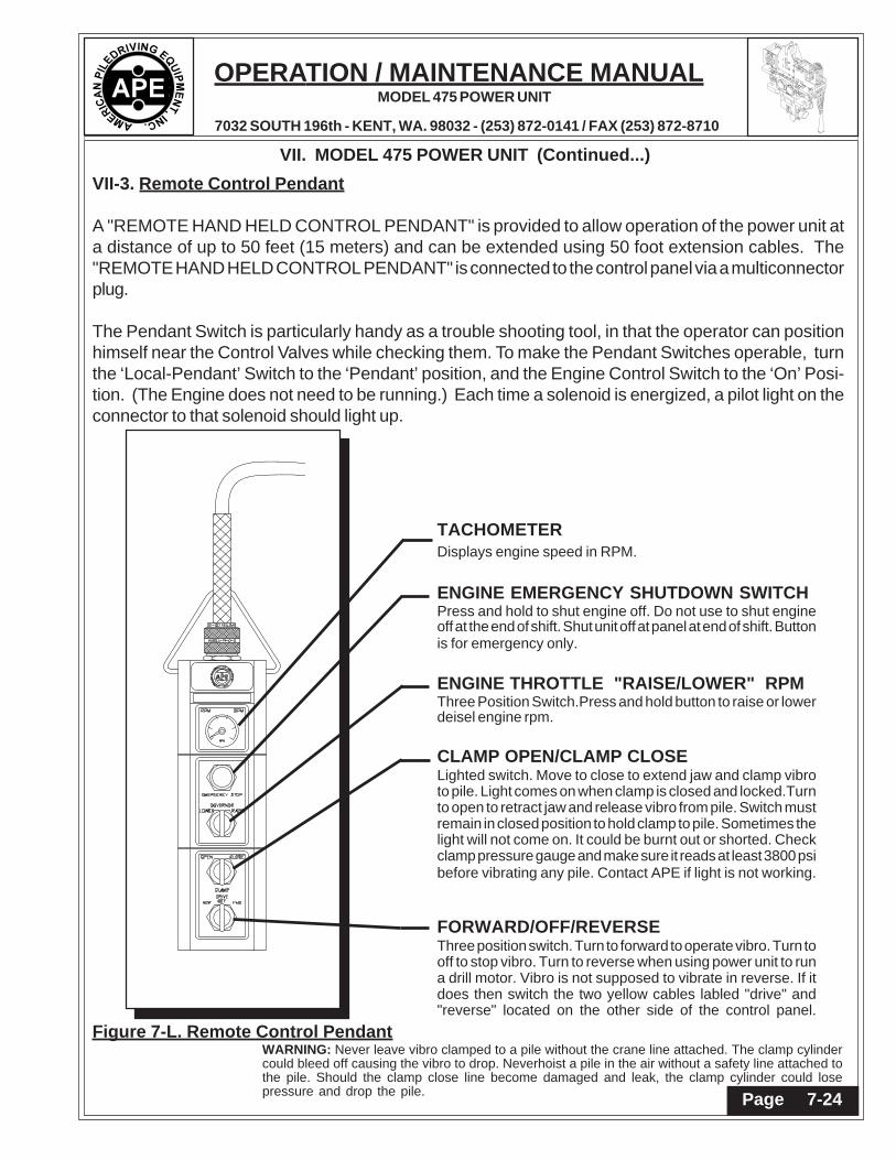
VII-3. Remote Control Pendant
A "REMOTE HAND HELD CONTROL PENDANT" is provided to allow operation of the power unit ata distance of up to 50 feet (15 meters) and can be extended using 50 foot extension cables. The"REMOTE HAND HELD CONTROL PENDANT" is connected to the control panel via a multiconnectorplug.
The Pendant Switch is particularly handy as a trouble shooting tool, in that the operator can positionhimself near the Control Valves while checking them. To make the Pendant Switches operable, turnthe ‘Local-Pendant’ Switch to the ‘Pendant’ position, and the Engine Control Switch to the ‘On’ Posi-tion. (The Engine does not need to be running.) Each time a solenoid is energized, a pilot light on theconnector to that solenoid should light up.
Figure 7-L. Remote Control PendantWARNING: Never leave vibro clamped to a pile without the crane line attached. The clamp cylindercould bleed off causing the vibro to drop. Neverhoist a pile in the air without a safety line attached tothe pile. Should the clamp close line become damaged and leak, the clamp cylinder could losepressure and drop the pile.
TACHOMETERDisplays engine speed in RPM.
ENGINE EMERGENCY SHUTDOWN SWITCHPress and hold to shut engine off. Do not use to shut engineoff at the end of shift. Shut unit off at panel at end of shift. Buttonis for emergency only.
ENGINE THROTTLE "RAISE/LOWER" RPMThree Position Switch.Press and hold button to raise or lowerdeisel engine rpm.
CLAMP OPEN/CLAMP CLOSELighted switch. Move to close to extend jaw and clamp vibroto pile. Light comes on when clamp is closed and locked.Turnto open to retract jaw and release vibro from pile. Switch mustremain in closed position to hold clamp to pile. Sometimes thelight will not come on. It could be burnt out or shorted. Checkclamp pressure gauge and make sure it reads at least 3800 psibefore vibrating any pile. Contact APE if light is not working.
FORWARD/OFF/REVERSEThree position switch. Turn to forward to operate vibro. Turn tooff to stop vibro. Turn to reverse when using power unit to runa drill motor. Vibro is not supposed to vibrate in reverse. If itdoes then switch the two yellow cables labled "drive" and"reverse" located on the other side of the control panel.
Page 7-21

OPERATION / MAINTENANCE MANUAL
7032 SOUTH 196th - KENT, WA. 98032 - (253) 872-0141 / FAX (253) 872-8710
MODEL 475 POWER UNIT
VII. MODEL 475 POWER UNIT (Continued...)
Page 7-25
VII-3A. Remote Pendant Wiring DiagramThe following is the pin wiring configuration and the wire colors of the amphenol connectors for theremote control pendant cable.
Figure 7-M. Remote Pendant Wiring Diagram
Page 7-22

OPERATION / MAINTENANCE MANUAL
7032 SOUTH 196th - KENT, WA. 98032 - (253) 872-0141 / FAX (253) 872-8710
MODEL 475 POWER UNIT
VII. MODEL 475 POWER UNIT (Continued...)
Engine Connector Wiring
Page 7-26Page 7-23

OPERATION / MAINTENANCE MANUAL
7032 SOUTH 196th - KENT, WA. 98032 - (253) 872-0141 / FAX (253) 872-8710
MODEL 475 POWER UNIT
- APPENDIX A -CAT C13 ENGINE
A-1. ENGINE OPERATION INSTRUCTIONSThe following sections are basic instructions for maintenance and operation of the APE Model475Power Unit Engines. All maintenance should be performed by qualified personnel who are familiarwith the equipment. (Consult the factory for additional information.)
A-1A. PRE-START INSPECTION AND PROCEDURES
1. Make a "walk-around" inspection of the engine and components for the oil, water or fuelleaks and general appearance. Correct minor adjustments before they develop into majorrepair jobs.
2.Check the crankcase oil level. Maintain the oil level between the ADD and FULL marks onthe dipstick. See OIL SPECIFICATIONS for type of oil to use.
3. Check oil level(s) on driven equipment.
WARNING: Check the engine coolant level when the engine is cool. If the engine is warm,steam may spray outward under high pressure and cause personal injury.
4. Check the engine jacket coolant level. Slowly turn the pressure cap until the cap isremoved. Maintain coolant level to the base of the fill pipe.
5. Check the fuel supply. Keep fuel tanks full, as partially filled tanks will collect moisture.See the FUEL SPECIFICATIONS for type of fuel.
KEEP THE FUEL SUPPLY CLEAN
6. Open the raw water valve on the engine jacket heat exchanger system (if so equipped).Prime the raw water pump if the raw water system has been drained.
7. Reset shutoff devices. See the topic, ATTACHMENTS, Emergency Shutoff Devices andAlarms. If the engine is equipped with an air safety shutoff control, and was tripped to theshutoff position, reset the latch to the run position.
8. Open the fuel supply valve. If the engine has not run for some time it may be necessaryto prime the system. See the topic, PRIMING THE FUEL SYSTEM.
9. Disconnect any battery charger which is not protected against starting motor drain.
10. Disengage the clutch, or open the circuit breaker on a generator set.
Page A-1Page A-1

OPERATION / MAINTENANCE MANUAL
7032 SOUTH 196th - KENT, WA. 98032 - (253) 872-0141 / FAX (253) 872-8710
MODEL 475 POWER UNIT
- APPENDIX A -CAT C13 ENGINE
A-1B. STARTING THE ENGINE.
CAUTION: Do not engage the starter when the flywheel is moving.
Electric Starting1. Move the governor control lever to approximate half engine speed position.
2. Use starting aids if required.
3. Push the START button; or turn the HEAT START switch to the START position, dependingupon the control the engine has. Release the control as soon as the engine starts.
For generator sets, place the AUTO-MAN switch in the MAN position to crank the engine. Assoon as the engine starts, and the engine speed reaches 600 rpm and oil pressure isapproximately 22 psi (1.5 kg /CM2), the starter motor will disconnect from the circuit. (TheSTOP position is used to stop the diesel engine.)
If the engine fails to start within 10 seconds, move the governor control lever to the fuel offposition, then continue to crank for 10 seconds. This will clear the cylinders of unburned fuel.
If the engine fails to start after 30 seconds of cranking, allow the engine to cool for 2 minutesbefore repeating the starting procedure.
CAUTION: Prolonged cranking at low oil pressure can activate the mechanical safety shut-off. If the reset lever is in the shut-off position, reset the mechanical shut-off control.
CAUTION: NEVER use starting aids when the engine Is warm and running.
Air Starting1. Open and close the bleed valve on the bottom of the air tank to drain condensation and oilcarryover.
2. Check the air supply pressure. The air start must have 100 PSI (7 kg/cm2) to operateproperly.
3. Keep oil level, in the oiler jar, at least half full. Add oil if necessary.
4. Push the air valve control in to crank the engine. As soon as the engine starts, release thevalve.
Page A-2 Page A-2

OPERATION / MAINTENANCE MANUAL
7032 SOUTH 196th - KENT, WA. 98032 - (253) 872-0141 / FAX (253) 872-8710
MODEL 475 POWER UNIT
- APPENDIX A -CAT C13 ENGINE
A-1. OPERATION INSTRUCTIONS. (Continued...)
A-1C. ENGINE OPERATION.After the engine starts, and at frequent intervals while the engine is operating, the gaugesshould be observed. Determine the normal reading for each gauge. Investigate the causewhenever there is a significant change in the reading.
TachometerThe tachometer indicates engine RPM. The high idle RPM and the full load RPM are stampedon the engine's information plate. The engine can be operated between these two speed limitsfor long periods of time without shortening engine life. Prolonged operation at high idle withlittle or no load can cause adverse engine operation.
Engine Oil PressureIf the gauge reading fluctuates after the load is stable:
1. Remove the load.
2. Reduce engine speed to low idle.
3. Observe the oil level. Maintain the oil level between the ADD and FULL mark on thedipstick. If the reading continues to fluctuate when the oil level is correct, stop engine and callyour Caterpillar dealer.
Engine Jacket Water TemperatureThe engine should operate within the NORMAL (green) range. If the engine is operating inthe (red) range and steam becomes apparent:
1. Reduce the load and engine RPM.
2. Inspect for coolant leaks.
3. Determine if the engine must be shut down immediately; or if the engine can be safelycooled by reducing the load. (See COOLING SPECIFICATION INSTRUCTIONS.)
CAUTION: Do not add cold water to a hot engine: Cracking of engine components mayoccur. Allow the engine to cool, then add coolant.
Page A-3Page A-3

OPERATION / MAINTENANCE MANUAL
7032 SOUTH 196th - KENT, WA. 98032 - (253) 872-0141 / FAX (253) 872-8710
MODEL 475 POWER UNIT
- APPENDIX A -CAT C13 ENGINE
A-1C. ENGINE OPERATION (Continued...)
-Water Temperature GaugeIf the temperature gauge reading registers in or near the cold range (white) while operatingunder load:
1. Check the water temperature gauge for accuracy.
2. Check the temperature regulators for proper temperature range. Replace regulators ifnecessary.
Fuel pressureIf the fuel filter gauge registers in the OUT range, clean the primary fuel filter, if so equipped.Install new secondary or final fuel filter elements if gauge still registers OUT. See the FUELMAINTENANCE INSTRUCTIONS and FUEL SPECIFICATIONS.
Ammeter:The ammeter reading is normal when the indicator is at or on the (+) side of zero, when theengine is running at rated speed. If indicator is to the left (-) side of zero, investigate andcorrect cause.
Air Cleaner Service IndicatorWhen the gauge indicator locks in the red range, service the air cleaner. With the enginestopped.
Calibrated GaugesCalibrated gauges are used on some engines to monitor the engine systems. If an abnormalengine condition develops, determine and analyze and correct the cause before a failure anddowntime occurs.
If any of the gauges register at or outside the operating limits, investigate and correct any malfunction.See TROUBLESHOOTING for guidance.
WARNING: Shut the engine down if work on or around the engine is required. DO NOT OPERATE THE ENGINE WITH THE GAUGES REGISTERING AT OR OUTSIDE
THE LIMITS.
Page A-4 Page A-4

OPERATION / MAINTENANCE MANUAL
7032 SOUTH 196th - KENT, WA. 98032 - (253) 872-0141 / FAX (253) 872-8710
MODEL 475 POWER UNIT
A-1C. ENGINE OPERATION (Continued...)
Altitude OperationThe fuel system settings and altitude limits are stamped on the engine information plate.When an engine is moved to a higher altitude, these settings must be changed by yourCaterpillar dealer in order to prevent damaging the turbocharger, and to provide maximumengine efficiency. If the engine is moved to a lower altitude than that which is stamped on theengine information plate, the engine can be operated safely; however, it will deliver less thanrated horsepower, and the fuel settings should be changed by your Caterpillar dealer to obtainrated horsepower.
Stopping1. Flywheel clutch operation: Quickly pull the clutch lever to the released position.
2. Reduce engine speed to half speed. Run for 5-10 minutes to cool engine.
3. Reduce engine speed to low idle.
4. Observe the crankcase oil level while the engine is idling. Maintain the oil level between the ADD and FULL marks on the side of the dipstick stamped, CHECK WITH ENGINE
RUNNING. See the LUBRICATION AND MAINTENANCE SECTION.
5. Stop the engine.
After Stopping Checks And Procedures
1. Fill the fuel tank. See the LUBRICATION AND MAINTENANCE SECTION: Fuel Tank Maintenance.
2. Drain the raw water system if below freezing temperatures are expected; see: Draining Raw Water System.
3. If below freezing temperatures are expected, allow the engine jacket water expansion tank to cool, then cheek the coolant for proper antifreeze protection. Add permanent-type antifreeze, if required.
4. Repair any leaks, make major adjustments, tighten loose bolts, etc.
5. Observe the Service Meter reading. Perform the periodic maintenance as instructed in the LUBRICATION AND MAINTENANCE CHART.
- APPENDIX A -CAT C13 ENGINE
Page A-5Page A-5

OPERATION / MAINTENANCE MANUAL
7032 SOUTH 196th - KENT, WA. 98032 - (253) 872-0141 / FAX (253) 872-8710
MODEL 475 POWER UNIT
Starting The Engine1. Perform all prestart checks outlined previously.
2. Place the CONTROL switch in the MANUAL position to crank the engine.
3. When the engine starts and engine rpm reaches 600 rpm and the oil pressure registers 22 psi (1.5 kg/cm2) the starting motor will automatically disconnect from the start circuit.
4. Start the load.
5. Regulate the engine speed with the RAISE LOWER switch to the required instrument panel gauge readings.
Stopping The Engine1. Remove the load.
2. Reduce engine speed to low idle: Push down and hold the RAISE-LOWER switch until the engine low idle speed is reached.
3. While the engine is idling, check the engine oil level. Oil level must be maintained between the ADD and FULL marks on the side of the dipstick marked "CHECK WITH ENGINE RUNNING".
4. Stop the engine.
(Solenoid Shutoff)a. Move the control switch to the STOP or OFF positions. (Do not confuse this with the "RAISE-LOWER" switch.)
(PSG Governor:)b. Move the shutoff lever forward, or hold the lever up, depending upon installation. Hold the lever in this position until the engine stops.
5. Fill the fuel tank. See the LUBRICATION AND MAINTENANCE section.
6. Drain the raw water system if below freezing temperatures are expected.
Observe the Service Meter reading. Perform the periodic maintenance as instructed in theLUBRICATION AND MAINTENANCE CHART.
- APPENDIX A -CAT C13 ENGINE
A-1C. ENGINE OPERATION (Continued...)
Page A-6 Page A-6

OPERATION / MAINTENANCE MANUAL
7032 SOUTH 196th - KENT, WA. 98032 - (253) 872-0141 / FAX (253) 872-8710
MODEL 475 POWER UNIT
A-1D. Determining Cause Of Shutdown
CAUTION: If the engine has been shutdown by a safety device, don't start the engine andplace it into service without having the cause of the shutdown investigated and corrected
Low Oil Pressure ChecksIf the low oil pressure shutoff control has stopped the engine, make the following checks:
1. Check the water temperature gauge. Determine if the engine was overheated. Check for external water leaks.
WARNING: Beware of steam or scalding water. Do not attempt to loosen the radiator capuntil the temperature gauge indicates the coolant has sufficiently cooled. Then, loosen
the cap slowly.
2. Check the oil level. Oil level must be between the ADD and FULL marks on the side of the dipstick stamped CHECK WITH ENGINE STOPPED.
3. If the oil level is below the ADD mark, check for oil spray and/or oil accumulations. If any are found, have the necessary repairs made. Before starting, add oil to the FULL mark.
4. Reset the shutoff control.
5. Remove the load and start the engine at its slowest speed. Be prepared to shut the engine down manually.
6. Be alert for unusual sounds or noises. If the engine knocks, stop the engine immediately and call your engine dealer.
7. If the engine blows excessive black exhaust or has excessive crankcase blow-by, the en gine may need reconditioning. Stop the engine and call your engine dealer.
8. If the engine runs satisfactorily, observe the oil pressure gauge. If satisfactory pressure is not indicated, shut the engine down; call your engine dealer.
9. If proper oil pressure is registered, check to see if the reset knob has moved to the run position. If the knob does not move, stop the engine. Check the shutoff control, the oil line, and the oil pressure gauge. Have necessary repairs made.
10. If the oil pressure gauge registers normal oil pressure, if the knob on the shutoff control moves to the run position, and if the engine operation is otherwise satisfactory, determine if the high water temperature shutoff may have shut down the engine.
- APPENDIX A -CAT C13 ENGINE
Page A-7Page A-7

OPERATION / MAINTENANCE MANUAL
7032 SOUTH 196th - KENT, WA. 98032 - (253) 872-0141 / FAX (253) 872-8710
MODEL 475 POWER UNIT
A-1D. Determining Cause Of Shutdown (Continued...)
High Water Temperature Checks-Engine Running
1. Determine if the load was too great for the engine - Reduce the load and allow the engine to cool while running.
2. If pressure steam or water leaks are visible, remove the load and stop the engine. Have necessary repairs made.
3. Check for collapsing or deteriorated water hoses. Have repairs made.
4. Check for noisy water pump operation. Have necessary repairs made.
5. Refill the cooling system with a solution of water and permanent-type antifreeze if below freezing temperatures are expected; or with a solution of approved water and Corrosion Inhibitor. Follow the instructions on the container.
WARNING: DO NOT remove the pressure cap on an overheated engine. The coolant isunder pressure and relieving the pressure will cause the coolant to flash into steam.
NOTE: If there is adequate coolant in the cooling system, gradual a I cooling is preferred by runningthe engine a half speed. This eliminates hot spots in the engine, and possible failure.
High Water Temperature Checks-Engine Stopped and Cold
1. Check coolant level. Determine if the coolant has proper antifreeze protection. A 50-50 solution of permanent-type antifreeze and approved water will give protection below -200F (-290C).
2. Check to be sure the raw water valve has been opened.
3. Check engine room vents and/or louvers. Be sure the engine is receiving sufficient air.
4. Be sure temperature regulators are operating at proper temperature range.
5. Inspect all water hoses carefully for collapsing, external and internal failures. Replace hoses as required.
6. Have the cooling system cleaned.
CAUTION: If severe or prolonged overheating has occurred, contact your engine dealer tohave your engine checked for possible damage.
- APPENDIX A -CAT C13 ENGINE
Page A-8 Page A-8

OPERATION / MAINTENANCE MANUAL
7032 SOUTH 196th - KENT, WA. 98032 - (253) 872-0141 / FAX (253) 872-8710
MODEL 475 POWER UNIT
A-2. MAINTENANCE RECOMMENDATIONSCAUTION: Never add coolant to an overheated engine; allow the engine to cool first.
CoolingCheck specific gravity of antifreeze solution frequently in cold weather to assure adequate protection.Coolant should be drained and replaced "Every 2000 Service Meter Units." With additions of CoolingSystem Inhibitor or the use of Coolant Conditioner Elements as recommended, the drain period canbe extended to "Every 4000 Service Meter Units."
All water is corrosive at engine operating temperature. The cooling system should be protected withinhibitor at all times regardless of concentration of antifreeze. This can be done by maintaining a 3%concentration of liquid Cooling System Inhibitor or by using Coolant Conditioner Elements.
Never use both the liquid cooling system inhibitor and coolant elements at the same time.
Do not use Cooling System Inhibitor or Coolant Conditioner Elements with Dowtherm 209 Full-FillCoolant.
Whenever draining and refilling cooling system, always recheck the coolant level when the enginereaches normal operating temperature.
Filling at over 5 U.S. gallons (1 9 liters) per minute can cause air pockets in the cooling system.
Premix antifreeze solution to provide protection to the lowest expected ambient temperature. Pureundiluted antifreeze will freeze at -10OF (-23,)C).
Operate with a thermostat in the cooling system all year-round. Cooling system problems can arisewithout a thermostat.
ElectricalCAUTION: When using jumper cables to start the engine, be sure to connect in parallel:
POSITIVE (+) to POSITIVE (+) and NEGATIVE (-) to NEGATIVE
Scheduled Oil SamplingUse scheduled Oil sampling to monitor the engine's condition and maintenance requirements. Eachoil sample should be taken when the oil is hot, and well mixed, to insure a sample which is representative of the oil in the compartment.
Consult your engine dealer for complete information, and assistance in establishing a Scheduled OilSampling program for your equipment.
- APPENDIX A -CAT C13 ENGINE
Page A-9Page A-9

OPERATION / MAINTENANCE MANUAL
7032 SOUTH 196th - KENT, WA. 98032 - (253) 872-0141 / FAX (253) 872-8710
MODEL 475 POWER UNIT
FuelCAUTION: Fill fuel tank at the end of each day of operation to drive out moisture laden airand to prevent condensation. Do not fill the tank to the brim. The fuel expands when it
gets warm and may overflow.
Water and sediment should be drained from the fuel tank at the start of each shift or after the fueltank has been filled and allowed to stand for 5 to 10 minutes.
Drain fuel tank of moisture and sediment as required by prevailing conditions.
After changing fuel filters, always bleed fuel system to remove air bubbles from system.
Air intakeService air cleaners when RED band in indicator locks in visible position.
A-2. MAINTENANCE RECOMMENDATIONS (Continued...)
A-2A. LUBRICATION SPECIFICATIONS
Crankcase Lubricating OilsUse oils which meet Engine Service Classification (MIL-L-2104D) or CD/TO-2. These areadditive-type oils that have been approved for use in Diesel Engines.
Consult the "EMA Lubricating Oils Data Book," Form SEBU5939, for a listing of CD oil brands.
The proper SAE grade of oil to select is determined by the ambient temperature at which theengine is started and the maximum ambient temperature in which the engine will be operating.
To determine if the oil in the crankcase will flow in cold weather, remove the oil dipstick beforestarting. If the oil will flow off, the oil is fluid enough to circulate properly.
Lubricating GreaseUse Multipurpose-type Grease (MPGM) which contains3-5% molybdenum disulfide conforming to MIL-M-7866, and a suitable corrosion inhibitor. NLGI No.2 Grade is suitable for mosttemperatures. Use NLGI No. 0 or No. 1 Grade for extremely low temperatures.
- APPENDIX A -CAT C13 ENGINE
Page A-10 Page A-10

OPERATION / MAINTENANCE MANUAL
7032 SOUTH 196th - KENT, WA. 98032 - (253) 872-0141 / FAX (253) 872-8710
MODEL 475 POWER UNIT
- APPENDIX A -CAT C13 ENGINE
A-2. MAINTENANCE RECOMMENDATIONS (Continued...)
A-2B. FUEL SPECIFICATIONSNo. 2 fuel oil and No. 2D diesel fuel are recommended for use in Diesel Engines. In extremecold temperatures use No. 1 fuel oil or No.1 D diesel fuel.
In selecting a fuel, note that distillate fuels are especially desirable because the fuel is heatedto a vaporous state and condensed, thus eliminating all sediment and residue.
A-2C. COOLANT SPECIFICATIONSWater used in the jacket water cooling system should be clean, and as free as possible fromscale forming minerals or corrosive chemicals. Artificially softened water should not be used.Treating the water with Coolant Inhibitor, or equivalent will help prevent the formation of rustand pitting. It will also retard, and in some cases completely eliminate, mineral deposits in theengine.
The most efficient and satisfactory corrosion protection for the cooling system is to maintainproper level of coolant inhibitor and antifreeze solution. The use of auxiliary water filters is notrecommended.
During freezing weather use the proper permanent type antifreeze and water solution toprevent freezing.
Before placing the engine in operation, make sure a 3% concentration of Corrosion Inhibitorhas been added to the cooling system. This 3% concentration must be maintained in coolingsystems which are filled with water and systems protected with ethylene glycol antifreezemixture, regardless of antifreeze concentration.
WARNING: Inhibitors contain alkali. Avoid contact with eyes. To prevent personal in-jury, avoid pro-longed or repeated contact with skin.
Page A-11Page A-11

OPERATION / MAINTENANCE MANUAL
7032 SOUTH 196th - KENT, WA. 98032 - (253) 872-0141 / FAX (253) 872-8710
MODEL 475 POWER UNIT
1234567890123456789012345678901212345678901234567890123456789012123456789012345678901234567890121212345678901234567890123456789012123456789012345678901234567890121234567890123456789012345678901212123456789012345678901234567890121234567890123456789012345678901212345678901234567890123456789012121234567890123456789012345678901212345678901234567890123456789012123456789012345678901234567890121212345678901234567890123456789012123456789012345678901234567890121234567890123456789012345678901212123456789012345678901234567890121234567890123456789012345678901212345678901234567890123456789012121234567890123456789012345678901212345678901234567890123456789012123456789012345678901234567890121212345678901234567890123456789012123456789012345678901234567890121234567890123456789012345678901212
A-2D. LUBRICATION AND MAINTENANCEThe LUBRICATION AND MAINTENANCE CHART lists all serviceable items commonly ordered on this engine.The maintenance tune intervals are expressed in "Operating Hours".
CAT C13 ENGINE
A-2. MAINTENANCE RECOMMENDATIONS (Continued...)
Daily 1500 Hoursor 1 Year
250 Hoursor 6 months
6000 Hoursor 3 Years
6000 Hoursor 2 Years
Weekly
Repeat DailyCheck
Repeat Daily andWeekly Check
Repeat PreviousIntervals Which
Are Due
Repeat PreviousIntervals
Repeat PreviousIntervals
Check operator'sreportCheck and bringto correct level- Engine Oil- CoolantVisually inspectfan.Visually inspectengine fordamage, leaks,loose or frayedbelts and corrector record forfuture action.Drain fuel-waterseparator.
11
1
Check air intakesystem for wearpoints or damageto piping, looseclamps, andleaks.Check air cleanerrestriction.Check and cleanair cleanerelement.Drain moisturefrom air tanks.
11 Change Lubricating
Oil.Change Lubricating OilFilters.Change Fuel Filter.Change Coolant Filter.Clean CrankcaseBreather.Check engine coolantconcentration level.Add make-up ifrequired.Replace final FuelFilter/Clean primaryFuel Filter. Drain waterfrom fuel tank.Inspect/ReplaceAlternator, Fan andAccessory Drive Belts.Inspect/Replace Hosesand Clamps.Lubricate Fan DriveBearings.Clean/Check Batteryelectrolyte level.
1212
12
1212
12
1212
Adjust valves andinjectors.Steam clean engine.Check torque onturbocharger mountingnuts.Check torque onengine mounting bolts.Replace hoses asrequired.Check/Adjust enginevalve lash.Check/Adjust low idlespeed.Test/Exchange fuelinjection nozzles.Inspect coolant pump.Clean cooling system.(Internal)Inspect/RebuildAlternator.
Clean coolingsystem and changecoolant andantifreeze.Inspect temperatureregulator.Inspect/Rebuildturbocharger.Inspect/Rebuildstarter.Check and adjustclutch.
1212
12
12
12
Clean and calibrate thefollowing:(Rebuild or exchange ifrequired.)- Injectors.- Fuel pump.- Air compressor.- Fan clutch.- Water pump.- Fan hub.- Fan idler pulleyassembly.- Vibration damper.
11
Follow the manufacturer's recommended maintenance procedures for the starter, alternator, generator, batteries, electrical components, enginebrake, exhaust brake, air compressor, freon compressor, and fan clutch.At each scheduled maintenance interval, perform all previous maintenance checks which are due for scheduled maintenance.
1212
1212
12
1212
11
1
1
1
11
12
1 1
11
1
1
11
1
11
121
11
11
1212
Page A-12 Page A-12

OPERATION / MAINTENANCE MANUAL
7032 SOUTH 196th - KENT, WA. 98032 - (253) 872-0141 / FAX (253) 872-8710
MODEL 475 POWER UNIT
12345678901234567891234567890123456789123456789012345678912345678901234567891234567890123456789
123456789012345123456789012345123456789012345123456789012345123456789012345123456789012345123456789012345123456789012345123456789012345123456789012345123456789012345123456789012345123456789012345123456789012345
12345678901234561234567890123456123456789012345612345678901234561234567890123456123456789012345612345678901234561234567890123456123456789012345612345678901234561234567890123456123456789012345612345678901234561234567890123456
A-2E. ELECTRICAL SYSTEMThe following topics describe care and maintenance of the electrical system components.These components functioning together produce the energy needed for operating theelectrical equipment on the engine and each is dependent upon the others for satisfactoryoperation. In the event of failure or improper operation, it is essential to check the entireelectrical system as a defect in one component can cause damage to another. Many electrical
` system problems can be traced to loose or corroded connections. Keep connections tight andmake sure the wiring insulation is in satisfactory condition. Most of the electrical systemtesting can be performed while the components are on the engine. It should be remembered,if a malfunction is found on test, the component must be removed for further testing, repairor replacement.
BatteryEvery 250 hours check the electrolyte level of each cell and the general condition of thebattery. Maintain the electrolyte level to the base of each vent well. The make-up water mustbe one of the following (in order of preference):1. Distilled water.2. Odorless, tasteless drinking water-3. Iron free water.
WARNING: Never add acid or electrolyte.
Cleaning BatteryMix a weak solution of baking soda and water. Apply the solution with a soft bristle brush.Be careful not to get cleaning solution into the battery. Thoroughly rinse the battery and batterytray with clean water. Apply grease to battery cable clamps and terminals and to all threads.
-Installing Battery1. Be sure the battery tray is clean and free of foreign objects.2. Be sure terminal posts and cable clamps are clean.3. Place the battery in the tray. Tighten the hold down clamps evenly until the battery is snug. Do not over tighten.4. Connect the "hot" terminal first. Be sure the top of the cable terminal is pushed down even with the top of the terminal post. Tighten the clamp firmly.
WARNING: Always connect the "hot" terminal first to minimize arcing. Otherwise injuryor damage could result.
5. Connect the "grounded" terminal last. Be sure the top of the cable terminal is pushed down even with the top of the terminal post. Tighten the clamp firmly.6. Apply a thin coating of grease over the cable clamps. terminals and hold down fasteners.
- APPENDIX A -CAT C13 ENGINE
Page A-13Page A-13

OPERATION / MAINTENANCE MANUAL
7032 SOUTH 196th - KENT, WA. 98032 - (253) 872-0141 / FAX (253) 872-8710
MODEL 475 POWER UNIT
12345678901234561234567890123456123456789012345612345678901234561234567890123456123456789012345612345678901234561234567890123456123456789012345612345678901234561234567890123456123456789012345612345678901234561234567890123456
123456789012345123456789012345123456789012345123456789012345123456789012345123456789012345123456789012345123456789012345123456789012345123456789012345123456789012345123456789012345123456789012345123456789012345
123456789012345678123456789012345678123456789012345678123456789012345678123456789012345678
Charging the Battery
WARNING: Never smoke in the area where batteries are being charged. Hydrogen gas isgiven off at each vent cap during charging. Hydrogen mixed with air is highly explosive.
1. Connect positive charger clamp to positive battery terminal.2. Connect negative charger clamp to negative battery terminal.3. Connect charger power cord to proper outlet.4. Allow battery to charge slowly.
CAUTION: If battery is charged too rapidly, the battery will be damaged.
5. After the battery is charged, disconnect charger power cord from outlet; remove chargerclamp from negative battery terminal; remove charger clamp from positive battery terminal.
- APPENDIX A -CAT C13 ENGINE
A-2E. ELECTRICAL SYSTEM (Continued...)
A-3. Engine Troubleshooting.
-TROUBLESHOOTING INDEX-
ITEM PROBLEM ITEM PROBLEM
1. Engine Fails to Start 16. Valve Lash Close-up2. Misfiring 17. Premature Engine Wear3. Stalls at Low Speed 18. Coolant in Engine Lubricating Oil4. Erratic Engine Speed 19. Excessive Black or Gray Smoke5. Low Power 20. Excessive White or Blue Smoke6. Excessive Vibration 21. Low Engine Oil Pressure7. Heavy Combustion Knock 22. High Lubricating Oil Consumption8. Valve Train Clicking Knock 23. Abnormal Engine Coolant Temperature9. Oil in Coolant 24. Starting Motor Fails to Crank10. Mechanical Knock 25. Alternator Fails to Charge11. Excessive Fuel Consumption 26. Alternator Charging Rate Low or Unsteady12. Loud Valve Train Noise 27. Alternator Charging Rate High13. Excessive Valve Lash 28. Alternator Noisy14. Valve Spring Retainer Free15. Slobber
Page A-14 Page A-14

OPERATION / MAINTENANCE MANUAL
7032 SOUTH 196th - KENT, WA. 98032 - (253) 872-0141 / FAX (253) 872-8710
MODEL 475 POWER UNIT
12345678901234567891234567890123456789123456789012345678912345678901234567891234567890123456789
123456789012345123456789012345123456789012345123456789012345123456789012345123456789012345123456789012345123456789012345123456789012345123456789012345123456789012345123456789012345123456789012345123456789012345
12345678901234561234567890123456123456789012345612345678901234561234567890123456123456789012345612345678901234561234567890123456123456789012345612345678901234561234567890123456123456789012345612345678901234561234567890123456
- APPENDIX A -CAT C13 ENGINE
A-3. Engine Troubleshooting. (Continued...)
Possible Causes
1. ENGINE FAILS TO START
No Fuel to Engine
Shutoff Solenoid Sticking*
Fuel Transfer Pump
Engine Improperly Timed
Glow Plug Failure
Automatic and Safety Shutoff Controls
*Optional Equipment
2. MISFIRING
Defective Fuel Injection Nozzleor Fuel Pump
Improper Valve Lash
Incorrect Fuel Injection Timing
Low Fuel Supply Pressure
Broken or Leaking High PressureFuel Line
Air in Fuel System
Bent or Broken Push Rod
Remedy
Check for empty fuel tank, plugged fuel tank connections, obstructed orkinked fuel suction lines, fuel transfer pump failure, or plugged fuel filters.
Solenoid must be energized to shut off engine. Actuate the control thatoperates the shutoff solenoid and listen for a clicking sound. If clickingsound is not evident and engine will not start, remove the solenoid. Againtry to start the engine. If the engine starts, the solenoid is bad. Replace thesolenoid.
At cranking speed, the fuel transfer pump should supply fuel to the engineat 3 PSI (20 kPa). If fuel pressure is less than 3 PSI (20 kPa), replace thefuel filter. Check for air in fuel system, sticking, binding or defective fuelbypass valve. If pressure is still low, replace the fuel transfer pump.
See your authorized dealer.
Check glow plugs.
Check shutoff controls to ensure they are set properly. See StartingProcedures.
Run the engine at the speed where the defect is most pronounced.Momentarily loosen the fuel line nut on the injection pump to "cut out" thatcylinder. Check each cylinder in this manner. If one is found whereloosening makes no difference in irregular operation, the pump and nozzlefor only that cylinder need be treated.
Set to specified clearance.
See your authorized dealer.
Checkfuel supply line for leaks or kinks, air in fuel system, sticking, binding,or defective fuel bypass valve. Repiace fuel filter. Check fuel pressure.Fuel transfer pump should supply fuel at 2O to 3OPSI (l.4to2.1kg/CM2) tothe engine when the engine is fully loaded.
Replace the line.
Find source of air entry and correct. Bleed system.
Replace push rod.
Page A-15Page A-15

OPERATION / MAINTENANCE MANUAL
7032 SOUTH 196th - KENT, WA. 98032 - (253) 872-0141 / FAX (253) 872-8710
MODEL 475 POWER UNIT
12345678901234561234567890123456123456789012345612345678901234561234567890123456123456789012345612345678901234561234567890123456123456789012345612345678901234561234567890123456123456789012345612345678901234561234567890123456
123456789012345123456789012345123456789012345123456789012345123456789012345123456789012345123456789012345123456789012345123456789012345123456789012345123456789012345123456789012345123456789012345123456789012345
123456789012345678123456789012345678123456789012345678123456789012345678123456789012345678
- APPENDIX A -CAT C13 ENGINE
A-3. Engine Troubleshooting. (Continued...)Possible Causes Remedy
4. ERRATIC ENGINE SPEED
Governor Control Linkage
Governor Failure
Adjust external linkage to obtain sufficient travel. Replace if damaged,bent, or linkage is too short.
Look for damaged or broken springs, linkage, or other components.Determine if the rack can be moved manually. If any distress is noted inany of these components, replace as necessary.*
5. LOW POWER
Fuel Nozzle Failure
Poor Quality Fuel
Turbocharger Carboned or OtherwiseDragging
Leaks in Air Induction System
Incorrect Fuel Injection Timing
Excessive Valve Lash
Low Fuel Supply Pressure
Run the engine at the speed where the defect is most pronounced.Momentarily loosen the fuel line nut on the injection pump to "cut out" thatcylinder. Check each cylinder in this manner. If one is found whereloosening makes no difference in irregular operation, the pump and nozzlefor only that cylinder need be tested.
Drain, clean and bleed fuel system. Replace fuel filter. Fill fuel tank withproper grade of fuel.
lnspect and repair or replace turbo charger as necessary.*
Check inlet manifold pressure. Check air cleaner for restriction.
See your authorized dealer.
Set to specified clearance.
Check fuel supply line for leaks or kinks, air in fuel system, sticking, bindingor defective fuel bypass valve. Replace fuel filter. Check fuel pressure.Fuel transfer pump should supply fuel to 2O to 3O PSI(l.4 to 2.1kg/CM2)tothe engine when the engine is fully loaded.
Re tighten.
6. EXCESSIVE VIBRATION
Loose, Worn or Defective Engine Mounts Tighten all mounting bolts securely. Replace componentsas necessary.
Loose Pulley and Damper
Loose or Worn Coupling on Inspect, align and tighten coupling to driven equipment.Driven Equipment
Defective Damper or Pulley Replace damper or pulley.
Misfiring See ITEM 2.
Page A-16 Page A-16

OPERATION / MAINTENANCE MANUAL
7032 SOUTH 196th - KENT, WA. 98032 - (253) 872-0141 / FAX (253) 872-8710
MODEL 475 POWER UNIT
12345678901234567891234567890123456789123456789012345678912345678901234567891234567890123456789
123456789012345123456789012345123456789012345123456789012345123456789012345123456789012345123456789012345123456789012345123456789012345123456789012345123456789012345123456789012345123456789012345123456789012345
12345678901234561234567890123456123456789012345612345678901234561234567890123456123456789012345612345678901234561234567890123456123456789012345612345678901234561234567890123456123456789012345612345678901234561234567890123456
- APPENDIX A -CAT C13 ENGINE
A-3. Engine Troubleshooting. (Continued...)
Possible Causes Remedy
7. HEAVY COMBUSTION KNOCK
Air in Fuel System Bleed air from system.
Defective Fuel Injection Pump Plunger Replace.*and Barrel Assembly
Defective Fuel Injection Nozzle Replace.
Incorrect Fuel Injection Timing See your authorized dealer.*
8. VALVE TRAIN CLICKING NOISE
Excessive Valve Lash Set to specified clearance.
Broken Valve Spring(s) Replace valve spring(s) and all other damaged components.*
Insufficient Lubrication Check lubrication in valve compartment. Should be very wet at all speeds.Oil passages should be cleaned, especially those leading to the cylinderhead.
9. OIL IN COOLANT
Failed Oil Cooler Core Replace oil cooler core.
Failed Head or Spacer Plate Gaskets Replace head and spacer plate gaskets.
Cracked or Defective Cylinder Block Replace cylinder block.*
Cracked or Defective Head Replace cylinder head.
10. MECHANICAL KNOCK
Engine Connecting Rod Bearing Replace the bearing. Check the connecting rod andFailure crankshaft. Replace if necessary.*
Main Bearing Failure Replace bearings.*
Damaged Timing Gear Train Replace components as necessary.*
Broken Crankshaft Replace crankshaft.*
Fuel Dilution of Crankcase Oil Correct fuel leakage into crankcase oil.
*Authorized dealers are equipped with the necessary tools and personnel familiar with disassembly procedures toperform these services.
Page A-17Page A-17

OPERATION / MAINTENANCE MANUAL
7032 SOUTH 196th - KENT, WA. 98032 - (253) 872-0141 / FAX (253) 872-8710
MODEL 475 POWER UNIT
12345678901234561234567890123456123456789012345612345678901234561234567890123456123456789012345612345678901234561234567890123456123456789012345612345678901234561234567890123456123456789012345612345678901234561234567890123456
123456789012345123456789012345123456789012345123456789012345123456789012345123456789012345123456789012345123456789012345123456789012345123456789012345123456789012345123456789012345123456789012345123456789012345
123456789012345678123456789012345678123456789012345678123456789012345678123456789012345678
- APPENDIX A -CAT C13 ENGINE
Possible Causes Remedy
11. EXCESSIVE FUEL CONSUMPTION
Fuel System Leaks Large changes in fuel consumption may result. Internal leaks willprobably be accompanied by low engine oil pressure and increased oillevel in the engine oil sump. Replace leaking components.
Fuel and Combustion Knock Small but measurable increases in fuel consumption maybe the result ofdefective fuel nozzles, misfiring or factors contributing to loss of power.See ITEM 2 and ITEM 5.
Incorrect Fuel Injection Timing See your authorized dealer.
12. LOUD VALVE TRAIN NOISE
Bent or Broken Valves Replace damaged parts.*
Broken Camshaft Replace all damaged parts. Clean engine thoroughly.
Broken or Severely Worn Valve Lifters Replace camshaft and valve lifters. Check for sticking valves and bentvalve stems. Clean engine thoroughly. Set valve lash to specified clearance.
13. EXCESSIVE VALVE LASH
Severely Worn Cam Lobes Check valve lash. Replace camshaft and followers. Clean enginethoroughly. Set valve lash to specified clearance.
Broken or Severely Worn Valve Lifters Replace valve lifters. Check camshaft for wear. Check for sticking valvesand bent valve stems. Clean engine thoroughly. Set valve lash to speci-fied clearance.
Valve Tip Wear Set valve lash to specif ied clearance. If wear is excessive, replace valve.
Moderate Valve Lifter Face Wear Set valve lash to specified clearance. Ifwear is excessive, replace valve lifter.
Push Rod Wear Set valve lash to specified clearance. If wear is excessive, replace pushrod.
Rocker Arm Anvil Wear Set valve lash to specified clearance. If wear is excessive, replace rockerarm.
Insufficient Lubrication Check lubrication in valve should be very wet at high idle speeds, but onlydamp at low idle. Oil passages should be cleaned, especially thoseleading to the cylinder head.
A-3. Engine Troubleshooting. (Continued...)
Page A-18 Page A-18

OPERATION / MAINTENANCE MANUAL
7032 SOUTH 196th - KENT, WA. 98032 - (253) 872-0141 / FAX (253) 872-8710
MODEL 475 POWER UNIT
12345678901234567891234567890123456789123456789012345678912345678901234567891234567890123456789
123456789012345123456789012345123456789012345123456789012345123456789012345123456789012345123456789012345123456789012345123456789012345123456789012345123456789012345123456789012345123456789012345123456789012345
12345678901234561234567890123456123456789012345612345678901234561234567890123456123456789012345612345678901234561234567890123456123456789012345612345678901234561234567890123456123456789012345612345678901234561234567890123456
- APPENDIX A -CAT C13 ENGINE
A-3. Engine Troubleshooting. (Continued...)
Possible Causes Remedy
14. VALVE SPRING RETAINER FREE
Broken Keepers Extensive engine damage may result from dropped valve.Replace all damaged parts.*
Broken Valve Spring Replace valve spring.*
Broken Valve Replace valve and any other damaged parts.*
15. SLOBBER
Excessive Valve Guide Wear Recondition cylinder head assembly.*
Excessive Lubricating Oil in Valve Check rocker arm shaft and plugs to assure that they areCompartment in place.
Worn Piston Rings and/or Liners Inspect and replace components as necessary.*
16. VALVE LASH CLOSE-UP
Valve Face and/or Seat Wear Adjust valves to specified clearance.Recondition cylinder head.
17. PREMATURE ENGINE WEAR
Intake Piping Failure (Air Cleaner) Inspect all gaskets and piping for leaks. Repair all leaks.
Excessive Fuel Dilution of Replace leaking components. This will probably be ac-Lubricating Oil companied by high fuel consumption and low engine oil pressure.
Tighten fuel injection line fittings under valve cover.
Dirt in Lubricating Oil Locate and correct source of dirt entry, Change lubricating oil.Change oil filter.
18. COOLANT IN ENGINE LUBRICATING OIL
Oil Cooler Failure Replace oil cooler core.
Cylinder Head Gasket Failure Replace gasket. Maintain proper torque on cylinder head bolts.
Cracked or Defective Cylinder Head Replace cylinder head.*
Cracked or Defective Cylinder Block Replace cylinder block.*
*Authorized dealers are equipped with the necessary tools and personnel familiar with disassembly and assemblyprocedures to perform these serviced.
Page A-19Page A-19

OPERATION / MAINTENANCE MANUAL
7032 SOUTH 196th - KENT, WA. 98032 - (253) 872-0141 / FAX (253) 872-8710
MODEL 475 POWER UNIT
12345678901234561234567890123456123456789012345612345678901234561234567890123456123456789012345612345678901234561234567890123456123456789012345612345678901234561234567890123456123456789012345612345678901234561234567890123456
123456789012345123456789012345123456789012345123456789012345123456789012345123456789012345123456789012345123456789012345123456789012345123456789012345123456789012345123456789012345123456789012345123456789012345
123456789012345678123456789012345678123456789012345678123456789012345678123456789012345678
- APPENDIX A -CAT C13 ENGINE
Possible Causes Remedy
18. COOLANT IN ENGINE LUBRICATING OIL (Cont'd)
Cylinder Liner Seal Leaking Replace seals.*
Cracked or Defective Cylinder Liners Replace cylinder liners.'
19. EXCESSIVE BLACK OR GRAY SMOKE
Insufficient Combustion Air Check air cleaner for restriction. Check inlet manifoldpressure. Inspect turbocharger for proper operation.
Fuel Nozzle Plugged or Leaking Replace nozzle.
Incorrect Fuel Injection Timing See your authorized dealer.
Fuel Ratio Control Improperly Adjusted Adjust fuel ratio control.*
20. EXCESSIVE WHITE OR BLUE SMOKE
Valve Guides Worn Recondition cylinder head assembly.*
Piston Rings Worn, Stuck or Broken Replace.*
High Crankcase Oil Level Avoid overfilling. Determine cause and drain excess oil.
Misfiring See ITEM 2.
Fuel Injection Pump Timing Wrong See your authorized dealer.
Air in Fuel System Bleed fuel system.
21. LOW ENGINE OIL PRESSURE
Engine Oil Diluted with Fuel Oil Check lip-type seal on fuel transfer pump driveshaft. Drain crankcase and refill with clean lubricant.
Excessive Crankshaft Bearing Replace bearings and/or crankshaft.* Check oil filterClearance operation.
Excessive Timing Gear Bearing Inspect bearings and replace components asClearances necessary.
Excessive Rocker Arm Bore or Check lubrication. Replace components as necessary.Rocker Arm Shaft Wear
Defective Oil Pump Repair or replace.*
Defective Suction Bell Replace.
A-3. Engine Troubleshooting. (Continued...)
Page A-20 Page A-20

OPERATION / MAINTENANCE MANUAL
7032 SOUTH 196th - KENT, WA. 98032 - (253) 872-0141 / FAX (253) 872-8710
MODEL 475 POWER UNIT
12345678901234567891234567890123456789123456789012345678912345678901234567891234567890123456789
123456789012345123456789012345123456789012345123456789012345123456789012345123456789012345123456789012345123456789012345123456789012345123456789012345123456789012345123456789012345123456789012345123456789012345
12345678901234561234567890123456123456789012345612345678901234561234567890123456123456789012345612345678901234561234567890123456123456789012345612345678901234561234567890123456123456789012345612345678901234561234567890123456
- APPENDIX A -CAT C13 ENGINE
A-3. Engine Troubleshooting. (Continued...)
Possible Causes Remedy
21. LOW ENGINE OIL PRESSURE (Cont'd)
Clogged Oil Filter or Cooler Repair or replace as necessary.
Oil Pump Relief Valve Stuck Clean valve and housing. Replace if necessary.
22. HIGH LUBRICATING OIL CONSUMPTION
Oil Leaks Replace gaskets or seals and tighten all connections.
Excessive Oil to Intake See ITEM 15. Valve Guides.
Excessive Valve Guide Wear See ITEM 15.
Crankcase Oil Level Too High Avoid overfilling. Determine cause and drain excessoil.
High Oil Temperature Check oil cooler bypass valve. Replace if defective.Clean oil cooler core.
Worn Piston Rings and/or Liner Replace components as necessary.*
23. ABNORMAL ENGINE COOLANT TEMPERATURE
Combustion Gases in Coolant Determine point at which gases enter the system.Repair or replace components as necessary.
Defective Water Temperature Regulator Check temperature regulator for proper openingor Temperature Gauge temperature and correct installation. Check
temperature gauge. Replace if necessary.
Coolant Level Low Determine cause-replace leaking gaskets andhoses. Tighten connections. Add coolant.
Air Flow Through Radiator Restricted Remove all debris from outer surface of radiator.
Defective Water Pump Check water pump impeller. Repair water pump asnecessary.
Radiator Small for Engine Application Install correct size radiator.
Fan Improperly Positioned in Shroud Position fan correctly.*or Not Shrouded
*Authorized dealers are equipped with the necessary tools and personnel familiar with disassembly and assemblyprocedures to perform these serviced.
Page A-21Page A-21

OPERATION / MAINTENANCE MANUAL
7032 SOUTH 196th - KENT, WA. 98032 - (253) 872-0141 / FAX (253) 872-8710
MODEL 475 POWER UNIT
12345678901234561234567890123456123456789012345612345678901234561234567890123456123456789012345612345678901234561234567890123456123456789012345612345678901234561234567890123456123456789012345612345678901234561234567890123456
123456789012345123456789012345123456789012345123456789012345123456789012345123456789012345123456789012345123456789012345123456789012345123456789012345123456789012345123456789012345123456789012345123456789012345
123456789012345678123456789012345678123456789012345678123456789012345678123456789012345678
- APPENDIX A -CAT C13 ENGINE
Possible Causes Remedy
23. ABNORMAL ENGINE COOLANT TEMPERATURE
Incorrect Fuel Injection Timing See your authorized dealer.
Incorrect Water Piping Connections Check shunt line (if equipped) andfrom Engine to Radiator vent line for correct installation.
24. STARTING MOTOR FAILS TO CRANK
Low Output from Battery Check battery and charge or replace.
Defective Wiring or Switch Repair or replace.
Defective Solenoid Replace.
Defective Starting Motor Repair.
25. ALTERNATOR FAILS TO CHARGE
Drive Belt Loose Adjust belt.
Open or High Resistance in Inspect all cables and connectors.Charging or Ground Return Clean, re tighten or replace defectiveCircuits or Battery Connections parts.
Excessively Worn, Open or Replace brush assembly.*Defective Brushes
Open Rotor Field Coil Replace rotor assembly.*
26. ALTERNATOR CHARGING RATE LOW OR UNSTEADY
Drive Belt Loose Adjust belt.
Intermittent or High Resistance in Inspect all cables and connectors.Charging or Ground Return Circuits Clean, re tighten or replace defectiveor Battery Connections parts.
Excessively Worn, Sticky, or Replace brush assembly.*Defective Brushes
Faulty Regulator Replace regulator.*
Shorted or Open Rectifier Diodes Replace defective rectifier diodeassembly in alternator.*
Grounded or Shorted Rotor Replace rotor assembly.*
A-3. Engine Troubleshooting. (Continued...)
Page A-22 Page A-22

OPERATION / MAINTENANCE MANUAL
7032 SOUTH 196th - KENT, WA. 98032 - (253) 872-0141 / FAX (253) 872-8710
MODEL 475 POWER UNIT
12345678901234567891234567890123456789123456789012345678912345678901234567891234567890123456789
123456789012345123456789012345123456789012345123456789012345123456789012345123456789012345123456789012345123456789012345123456789012345123456789012345123456789012345123456789012345123456789012345123456789012345
12345678901234561234567890123456123456789012345612345678901234561234567890123456123456789012345612345678901234561234567890123456123456789012345612345678901234561234567890123456123456789012345612345678901234561234567890123456
- APPENDIX A -CAT C13 ENGINE
A-3. Engine Troubleshooting. (Continued...)
Possible Causes Remedy
27. ALTERNATOR CHARGING RATE HIGH
Loose Connections Tighten connections to alternator and regulator.
Defective Regulator Replace regulator.
28. ALTERNATOR NOISY
Defective Drive Belt Replace belt.
Misaligned Belt or Pulley Align drive pulley, alternator pulley and belt.
Loose Pulley Tighten pulley nut. If keyway is worn, install a new pulley.
Worn Bearings Replace bearings.
Shorted Rectifiers in Alternator Replace diode assembly.*
Armature or Rotor Shaft Bent Replace component.*
*Authorized dealers are equipped with the necessary tools and personnel familiar with disassembly and assemblyprocedures to perform these serviced.
Page A-23Page A-23

OPERATION / MAINTENANCE MANUAL
7032 SOUTH 196th - KENT, WA. 98032 - (253) 872-0141 / FAX (253) 872-8710
MODEL 475 POWER UNIT
12345678901234561234567890123456123456789012345612345678901234561234567890123456123456789012345612345678901234561234567890123456123456789012345612345678901234561234567890123456123456789012345612345678901234561234567890123456
123456789012345123456789012345123456789012345123456789012345123456789012345123456789012345123456789012345123456789012345123456789012345123456789012345123456789012345123456789012345123456789012345123456789012345
123456789012345678123456789012345678123456789012345678123456789012345678123456789012345678
123456789012345678123456789012345678123456789012345678123456789012345678123456789012345678123456789012345678123456789012345678123456789012345678123456789012345678123456789012345678123456789012345678
80 dB @ 50 feet15 meters
58 dB @ 100 feet33 meters
APE Model 475Power Unit
Maximum rpm
NOISE LEVEL OF APE MODEL 475 POWER UNIT
Note: Decibel level can be further reduced by operating at a lower engine rpm.The above chart is based on the power unit at full rpm. In most cases, in is notnecessary to run the engine at full rpm to drive or extract piles or when using thepower unit for drilling operations.
50 100
Page 64
Page A-3Page A-3
Page A-24