MODEL 2231P (P,T,G) DIGITAL FLOW COMPUTER file_____ MODEL 2231P DIGITAL FLOW COMPUTER WARRANTY...
154
MODEL 2231P (P,T,G) DIGITAL FLOW COMPUTER __________________________________________ DANIEL MEASUREMENT AND CONTROL HOUSTON, TEXAS Part Number: 3-9000-321 Revision B MAY 1996
Transcript of MODEL 2231P (P,T,G) DIGITAL FLOW COMPUTER file_____ MODEL 2231P DIGITAL FLOW COMPUTER WARRANTY...

MODEL 2231P (P,T,G)DIGITALFLOW COMPUTER__________________________________________
DANIEL MEASUREMENT AND CONTROLHOUSTON, TEXAS
Part Number: 3-9000-321Revision B
MAY 1996


MODEL 2231P DIGITAL FLOW COMPUTER ___________________________
DANIEL INDUSTRIES, INC.MODEL 2231P (P,T,G)
DIGITAL FLOW COMPUTERFOR DIFFERENTIAL HEAD METERS
GROSS METHOD 2 IMPLEMENTATION
NOTICE
DANIEL INDUSTRIES, INC. AND DANIEL MEASUREMENT AND CONTROL ("DANIEL")SHALL NOT BE LIABLE FOR TECHNICAL OR EDITORIAL ERRORS IN THIS MANUALOR OMISSIONS FROM THIS MANUAL.DANIEL MAKES NO WARRANTIES, EXPRESSOR IMPLIED, INCLUDING THE IMPLIED WARRANTIES OF MERCHANTABILITYAND FITNESS FOR A PARTICULAR PURPOSE WITH RESPECT TO THIS MANUALAND, IN NO EVENT, SHALL DANIEL BE LIABLE FOR ANY SPECIAL ORCONSEQUENTIAL DAMAGES INCLUDING, BUT NOT LIMITED TO, LOSS OFPRODUCTION, LOSS OF PROFITS, ETC.
PRODUCT NAMES USED HEREIN ARE FOR MANUFACTURER OR SUPPLIERIDENTIFICATION ONLY AND MAY BE TRADEMARKS/REGISTERED TRADEMARKS OFTHESE COMPANIES.
COPYRIGHT © 1995BY DANIEL MEASUREMENT AND CONTROL
HOUSTON, TEXAS, U.S.A.
All rights reserved. No part of this work may be reproduced orcopied in any form or by any means - graphic, electronic ormechanical - without first receiving the written permission ofDaniel Measurement and Control, Houston, Texas, U.S.A.
____________________________________________________________________
PREFACE i

___________________________MODEL 2231P DIGITAL FLOW COMPUTER
WARRANTY
Daniel Measurement and Control ("Daniel") warrants all equipment manufactured by it to be freefrom defects in workmanship and material, provided that such equipment was properly selectedfor the service intended, properly installed, and not misused. Equipment which is returned,transportation prepaid to Daniel within twelve (12) months of the date of shipment (eighteen (18)months from date of shipment for destinations outside of the United States), which is found afterinspection by Daniel to be defective in workmanship or material, will be repaired or replaced atDaniel’s sole option, free of charge, and return-shipped at lowest cost transportation. Alltransportation charges and export fees will be billed to the customer. Warranties on devicespurchased from third party manufacturers not bearing a Daniel label shall have the warrantyprovided by the third party manufacturer.
Extended warranty -Models 2470, 2480 and 2500 are warranted for a maximum of twenty-four(24) months. The Danalyzer valves are warranted for the life of the instrument and the columnsfor five years.
The warranties specified herein are in lieu of any and all other warranties, express or implied,including any warranty of merchantability or fitness for a particular purpose.
Daniel shall be liable only for loss or damage directly caused by its sole negligence. Daniel’sliability for any loss or damage arising out of, connected with, or resulting from any breachhereof shall in no case exceed the price allocable to the equipment or unit thereof which givesrise to the claim. Daniel’s liability shall terminate one year after the delivery of the equipmentexcept for overseas deliveries and extended warranty products as noted above.
In no event, whether as a result of breach of warranty or alleged negligence, shall Daniel beliable for special or consequential damages, including, but not limited to, loss of profits orrevenue; loss of equipment or any associated equipment; cost of capital; cost of substituteequipment, facilities or services; downtime costs; or claims of customers of the purchaser forsuch damages.
____________________________________________________________________
PREFACEii

MODEL 2231P DIGITAL FLOW COMPUTER ___________________________
TABLE OF CONTENTS
1.0 INTRODUCTION . . . . . . . . . . . . . . . . . . . . . . . . . . . . . . . . . . . . 1-1
1.1 GENERAL . . . . . . . . . . . . . . . . . . . . . . . . . . . . . . . . . . . . 1-1
1.1.1 HARDWARE . . . . . . . . . . . . . . . . . . . . . . . . . . . . . . 1-2
1.2 SPECIFICATIONS. . . . . . . . . . . . . . . . . . . . . . . . . . . . . . . 1-3
1.2.1 INPUTS. . . . . . . . . . . . . . . . . . . . . . . . . . . . . . . . . . 1-3
1.2.2 OUTPUTS. . . . . . . . . . . . . . . . . . . . . . . . . . . . . . . . 1-4
1.2.3 DISPLAYS. . . . . . . . . . . . . . . . . . . . . . . . . . . . . . . . 1-7
1.2.4 CONTROLS. . . . . . . . . . . . . . . . . . . . . . . . . . . . . . . 1-9
1.2.5 ACCURACY . . . . . . . . . . . . . . . . . . . . . . . . . . . . . .1-11
1.2.6 OTHER . . . . . . . . . . . . . . . . . . . . . . . . . . . . . . . . . .1-12
2.0 INSTALLATION AND INITIAL STARTUP . . . . . . . . . . . . . . . . . 2-1
2.1 GENERAL . . . . . . . . . . . . . . . . . . . . . . . . . . . . . . . . . . . . 2-1
2.2 UNPACKING . . . . . . . . . . . . . . . . . . . . . . . . . . . . . . . . . . 2-1
2.3 DAMAGE IN SHIPMENT . . . . . . . . . . . . . . . . . . . . . . . . . 2-1
2.4 SHIPPING INSTRUCTIONS . . . . . . . . . . . . . . . . . . . . . . . 2-2
___________________________________________________________________
TABLE OF CONTENTS iii

___________________________MODEL 2231P DIGITAL FLOW COMPUTER
2.5 INSTALLATION . . . . . . . . . . . . . . . . . . . . . . . . . . . . . . . . 2-2
2.5.1 DETERMINING OPTIONS. . . . . . . . . . . . . . . . . . . . 2-2
2.5.2 CASE MOUNTING . . . . . . . . . . . . . . . . . . . . . . . . . 2-4
2.5.3 ACCESS TO PLUG-IN PRINTED CIRCUIT BOARDS 2-4
2.5.4 WIRING THE MODEL 2231P. . . . . . . . . . . . . . . . . . 2-5
2.5.5 CONTROLLING EXTERNAL INDUCTIVE
CIRCUITS . . . . . . . . . . . . . . . . . . . . . . . . . . . . . . . . 2-6
2.6 START UP . . . . . . . . . . . . . . . . . . . . . . . . . . . . . . . . . . . . 2-8
2.6.1 GENERAL . . . . . . . . . . . . . . . . . . . . . . . . . . . . . . . . 2-8
2.6.2 START UP PROMPTING SEQUENCE. . . . . . . . . . . .2-10
2.6.3 SUPPLEMENTARY START UP INSTRUCTIONS . . . 2-26
3.0 OPERATION . . . . . . . . . . . . . . . . . . . . . . . . . . . . . . . . . . . . . . . 3-1
3.1 GENERAL . . . . . . . . . . . . . . . . . . . . . . . . . . . . . . . . . . . . 3-1
3.2 CALCULATIONS - PER STATION . . . . . . . . . . . . . . . . . . 3-1
3.3 OPERATIONAL OVERVIEW . . . . . . . . . . . . . . . . . . . . . .3-12
3.4 BASIC KEYBOARD/DISPLAY FUNCTIONS . . . . . . . . . . .3-19
3.4.1 SELECTING TEMPORARY OR PERMANENT
___________________________________________________________________
TABLE OF CONTENTSiv

MODEL 2231P DIGITAL FLOW COMPUTER ___________________________
DISPLAY . . . . . . . . . . . . . . . . . . . . . . . . . . . . . . . .3-19
3.4.2 VALIDITY CHECKS OF DATA ENTRIES. . . . . . . . . 3-19
3.4.3 FUNCTIONS OF SPECIFIC KEYS. . . . . . . . . . . . . .3-20
3.4.4 INDICATORS . . . . . . . . . . . . . . . . . . . . . . . . . . . . .3-22
3.5 DATA INPUT AND OVERRIDING CONTROLS. . . . . . . . . 3-23
3.5.1 ENTERING AN OPERATOR - SELECTED VALUE . . 3-24
3.5.2 SWITCHING MEASURED AND OPERATOR
ENTERED VALUES . . . . . . . . . . . . . . . . . . . . . . . . .3-25
3.6 DATA ACCESS . . . . . . . . . . . . . . . . . . . . . . . . . . . . . . . .3-29
3.6.1 TRANSDUCER SCALING . . . . . . . . . . . . . . . . . . . .3-30
3.6.2 MEASUREMENTS. . . . . . . . . . . . . . . . . . . . . . . . . .3-31
3.6.3 OPERATOR-ENTERED DATA CONSTANTS. . . . . . 3-32
3.6.4 COMPUTER CALCULATED VARIABLES . . . . . . . . 3-39
3.6.5 OUTPUT SCALING . . . . . . . . . . . . . . . . . . . . . . . . .3-46
3.7 COMPUTER ACTION REQUESTS. . . . . . . . . . . . . . . . . . .3-48
3.7.1 OPERATIONAL ACTIONS. . . . . . . . . . . . . . . . . . . .3-49
3.7.2 DIAGNOSTIC AID ACTIONS. . . . . . . . . . . . . . . . . .3-50
3.7.3 PARAMETER DISPLAY ACTIONS. . . . . . . . . . . . . .3-53
___________________________________________________________________
TABLE OF CONTENTS v

___________________________MODEL 2231P DIGITAL FLOW COMPUTER
3.7.4 CLEARING ACTIONS . . . . . . . . . . . . . . . . . . . . . . .3-54
3.8 SERIAL OUTPUT FOR PRINTING . . . . . . . . . . . . . . . . . .3-56
3.8.1 READ CODE USAGE. . . . . . . . . . . . . . . . . . . . . . . .3-58
3.8.2 DELAY (DLY) - READ CODE 44 . . . . . . . . . . . . . . .3-58
3.8.3 DATE (DTE) - READ CODE 45 . . . . . . . . . . . . . . . .3-58
3.8.4 REAL TIME CLOCK (TIM) - READ CODE 46 . . . . . 3-59
3.8.5 DAILY PRING TIME (DPT) - READ CODE 47. . . . . 3-59
3.8.6 PRINT INTERVAL (INT) - READ CODE 48 . . . . . . . 3-59
3.8.7 IDENTIFICATION (ID) - READ CODE 49. . . . . . . . . 3-60
3.8.8 BAUD RATE (BUD) - READ CODE 50. . . . . . . . . . .3-60
3.8.9 PRINT TABLE (P01 - P32) - READ CODES 51 - 82 . . 3-60
3.8.10 PRINT FORMAT. . . . . . . . . . . . . . . . . . . . . . .3-61
4.0 BENCH CALIBRATION . . . . . . . . . . . . . . . . . . . . . . . . . . . . . . . 4-1
4.1 GENERAL . . . . . . . . . . . . . . . . . . . . . . . . . . . . . . . . . . . . 4-1
4.1.1 CIRCUIT BOARD REVISIONS. . . . . . . . . . . . . . . . . 4-1
4.2 BENCH CALIBRATION PROCEDURE . . . . . . . . . . . . . . . 4-3
4.2.1 DETERMINE THE INSTRUMENT OPTIONS. . . . . . . 4-3
___________________________________________________________________
TABLE OF CONTENTSvi

MODEL 2231P DIGITAL FLOW COMPUTER ___________________________
4.2.2 PROCEDURE. . . . . . . . . . . . . . . . . . . . . . . . . . . . . . 4-3
4.2.3 TEST EQUIPMENT . . . . . . . . . . . . . . . . . . . . . . . . . 4-4
4.2.4 POWER SUPPLY ADJUSTMENTS. . . . . . . . . . . . . . 4-4
4.3 FIELD CALIBRATION . . . . . . . . . . . . . . . . . . . . . . . . . . . 4-5
4.3.1 RATE VOLTAGE CALIBRATION . . . . . . . . . . . . . . 4-5
4.3.2 RATE CURRENT CALIBRATION. . . . . . . . . . . . . . . 4-5
4.3.3 REFERENCE VOLTAGE CALIBRATION. . . . . . . . . 4-6
5.0 MAINTENANCE . . . . . . . . . . . . . . . . . . . . . . . . . . . . . . . . . . . . 5-1
5.1 GENERAL . . . . . . . . . . . . . . . . . . . . . . . . . . . . . . . . . . . . 5-1
5.2 PREVENTIVE MAINTENANCE . . . . . . . . . . . . . . . . . . . . 5-1
5.3 RECOMMENDED SPARE PARTS. . . . . . . . . . . . . . . . . . . 5-1
5.4 FACTORY SERVICE FAILURE REPORT . . . . . . . . . . . . . . 5-1
5.5 SHIPPING INSTRUCTIONS . . . . . . . . . . . . . . . . . . . . . . . 5-1
6.0 DRAWINGS AND PARTS LIST . . . . . . . . . . . . . . . . . . . . . . . . . 6-1
___________________________________________________________________
TABLE OF CONTENTS vii

___________________________MODEL 2231P DIGITAL FLOW COMPUTER
This page intentionally left blank.
___________________________________________________________________
TABLE OF CONTENTSviii

MODEL 2231P DIGITAL FLOW COMPUTER ___________________________
1.0 INTRODUCTION
1.1 GENERAL
The Model 2231P (P,T,G) Flowmaster Digital flow computer is a microprocessor basedinstrument which is used with differential head meters to measure and display flow rate and totalflow. FPV is calculated either from the 1992 AGA-8 gross method or from matrix densitypoints. Premium base flow totals for base level 1 and level 2 are calculated from operator-entered setpoints.
This manual covers the standard Daniel Model 2231P Flow Computer and resulting softwarerevisions.
The Software revisions include:
A. Delete flow calculations and all operator access (read codes, command codes, error codes)associated with 1969 revision of standard AGA-3.
B. Add flow calculations for volume flow in accordance with the 1992 revision of MPMSChapter 14.3 (ANSI/API 2530, AGA-3). This includes all read codes, command codes,and error codes.
C. Delete computation of supercompressibility for NX-19 and replace with densitycalculation per Gross Method 2 of 1992 Edition of AGA-8.
___________________________________________________________________
SECTION 1 1-1

___________________________MODEL 2231P DIGITAL FLOW COMPUTER
1.1.1 HARDWARE
The computer is contained in a standard Daniel Industries, Inc. industrial housing which is 4inches wide by 8 1/16 inches high by 21 5/16 inches long. These dimensions include anexternally mounted 24 Vdc or 115/230 Vac power supply at the rear of the unit. Internally, thecomputer contains either one or two plug-in printed circuit boards, depending upon the optionsselected by the customer.
___________________________________________________________________
INTRODUCTION1-2

MODEL 2231P DIGITAL FLOW COMPUTER ___________________________
1.2 SPECIFICATIONS
1.2.1 INPUTS
Pressure, Differential Pressure and Temperature
1. Number of Inputs -
One - Static Pressure, scaled in PSIAFive - Differential Pressure, scaled in inches of water.One - Gravity, scaled in SGU.One - Temperature, scaled in F.
2. Type Input - Differential for 4 - 20 mAsignal from any range transducer within the rangeof:
0 - 5000 PSIA for Static Pressure (0 - 1750 PSIA for AGA-8)0 - 1000 inches of water for Differential Pressure.0001 minimum SGU for Gravity-400oF minimum for Temperature (17.0 - 143.0 for AGA-8)
3. Differential Input Range - 3 to 21 mA.4. Differential Input Resistance - 250 Ohms. ±0.05%.5. Differential Input Filter - -52 db @ 60 Hz.6. Common Mode Input Range - 0 V to +15 Vwith respect to "common".7. Common Mode Input Resistance - Greater than 10 meg Ohms.8. Common Mode Rejection Ratio - Greater than 2000: 1.
___________________________________________________________________
SECTION 1 1-3

___________________________MODEL 2231P DIGITAL FLOW COMPUTER
1.2.2 OUTPUTS
A. 0 - 10 Volts Flow Rate
1. Range - Zero to +10.00 V signal, scalable by keyboard entry to represent from0.00 to N standard cubic feet per hour. Absolute maximum range is 0.00 to 10.62volts.
2. Maximum Load - 5 mA (2 K Ohms, minimum).3. Response Time - Differential pressure input to flow rate output - 2 seconds,
typical.
B. 4 - 20 mA Flow Rate
1. Range - 4 to 20 mAsignal scalable by keyboard entry to represent from 0.00 toN standard cubic feet per hour. Absolute maximum range is 4 to 21 mA.
2. Maximum Load Resistance - 900 Ohms (18V) to common.3. Response Time - Differential Pressure Input to Rate Output - 2 seconds typical.
C. Contact Closure Outputs
1. Number of contact closure outputs - Four
Volume Total· Premium Base Total· Premium Level 1 Total· Premium Level 2 Total
2. Rating - Form A contact, 30 Vdc or ac, 0.75A, 10 VA resistive, 3.5 VA inductive.
NOTE: For inductive loads, the user is responsible for providing arc suppression for thecontact closure.
3. Scaling - One closure per least significant digit advance of the displayed value.4. Maximum Rate - 25 closures per second.5. Duration - 20 ms, nominal.
___________________________________________________________________
INTRODUCTION1-4

MODEL 2231P DIGITAL FLOW COMPUTER ___________________________
D. Contact Closure Outputs - Status
1. Number of contact closure outputs - twoPremium Level 1 StatusPremium Level 2 Status
2. Contacts close when station flow exceeds operator-entered setpoint for respectivepremium level.
3. Rating - Form A contact, 30 Vdc or ac, 0.75, VA resistive, 3.5 VA inductive.
NOTE: For inductive leads, the user is responsible for providing arc suppression for thecontact closure.
E. Alarm Contact Closure
1. Rating - Form C contact, 30 Vdc or ac, 0.75 Amp, 10 VA resistive, 3.5 VAinductive.
NOTE: For inductive loads, the user is responsible for providing resistive/capacitivesuppression for the contact.
2. Function - Changes state to indicate power failure, processor failure, or otheralarm condition. The operation isfail safe. The relay is held in a normallyenergized state. Upon any fault, including loss of power, the relay is de-energized.
___________________________________________________________________
SECTION 1 1-5

___________________________MODEL 2231P DIGITAL FLOW COMPUTER
F. Serial Output
1. Baud Rate - Operator selectable. Standard rates from 150 to 2400 baud.2. Type - Ten bits in ASCII serial form.3. Voltage Levels - RS232C. +12V to -12V
Logic 0 - +3 Volts minimum.Logic 1 - -3 Volts minimum.
4. Character Frequency - Maximum 1 character per 20 msec., regardless of baud rate.
G. Transducer Power - Regulated +24 Vdc, 300 mA. Ripple, 100 mV maximum for 300 mAresistive load.
___________________________________________________________________
INTRODUCTION1-6

MODEL 2231P DIGITAL FLOW COMPUTER ___________________________
1.2.3 DISPLAYS (Refer to Figure 1-1)
A. Eight-digit alpha/numeric
1. Sixteen-segment LED.2. Full 64-character ASCII Code.
B. Six-digit mechanical counter without reset, for Station Net totals (See option diagram).
C. Status indicators
1. Red LED - indicates a current error or alarm condition. This LED is ON if eitherthe Watch-dog Timer has timed out or another condition exists.
2. Yellow LED - Indicates that an error condition has occurred since all errors werelast cleared via the keyboard even though the error condition no longer exists.
3. Green LED - Indicates that the operator may enter or change data in the computervia the keyboard. The enter/change capability is enabled by placing theenable/disable switch in PC board No.1 in the ENABLE position.
___________________________________________________________________
SECTION 1 1-7

___________________________MODEL 2231P DIGITAL FLOW COMPUTER
Figure 1-1. Model 2231 Display
___________________________________________________________________
INTRODUCTION1-8

MODEL 2231P DIGITAL FLOW COMPUTER ___________________________
1.2.4 CONTROLS
A. Enable/Disable Switch - Located on PC Board No.1 (Figure 1-2)
1. ENABLE position - Permits the operator to enter or change critical constants orscaling. NOTE - Does not stop computer calculation.
2. DISABLE position - Prevents using the keyboard to enter or change criticalconstants or scaling.
Figure 1-2. PC Board No. 1 (Revised version P/N DE-10421)
NOTE: Although there are two versions of PC Board No. 1 (Originalversion P/N DE-8992 and Revised version P/N DE-10421), thelocation and function of switch S1 is the same for both.
___________________________________________________________________
SECTION 1 1-9

___________________________MODEL 2231P DIGITAL FLOW COMPUTER
B. Keyboard - 24 Keys (Refer to Figure 1-1)
1. Enter (ENTR) - Inputs into memory any valid data shown on the Alpha/Numericdisplay.
2. Display (DSPY) - Recalls blanked data to the display when operation is in"display timeout" (see Subsection 3.7.1).
3. Numerals, period (.), and minus sign (-) - For entering numerical data or functioncodes.
4. Read (READ) - Entering a one- two- or three-digit function numerical code anddepressing READ displays the data being used or calculated by the computer (seeTable 3-1).
5. Fixed (FXD) - Depressing FXD displays data stored in the computer by theoperator (e.g., pressure, temperature, gravity, etc.). An asterisk displayed with thedata identifier indicates that the computer isnot currently using the data value forits computations.
6. Variable (VAR) - Depressing VAR displays data from a transducer or a computercalculation. An asterisk displayed with the data identifier indicates that thecomputer isnot currently using the data for its computations.
7. Clear (CLR) - Depressing CLR removes entered data values from the data codedisplayed and displays "0.0".
___________________________________________________________________
INTRODUCTION1-10

MODEL 2231P DIGITAL FLOW COMPUTER ___________________________
8. Command (CMD) - Entering a one- two- or three-digit numerical code anddepressing CMD causes the computer to execute the specified command (seeTable 3-1). These commands include the display of errors and the resetting oftotals. (Totals can be reset only when the green LED is lighted).
9. Up Arrow (↑) - Depressing↑ results in the following actions by the computer:
a. Reading data -↑ causes the computer to backstep to the previous datacode. For example, if the data corresponding to Read Code 2 is beingviewed, depressing↑ causes the computer to display the datacorresponding to Read Code 1.
b. Entering data -↑ indicates to the computer that the data to follow is anexponent (e.g., 2↑ 5= 2 x 105=200,000).
10. Down Arrow (↓) - Depressing↓ reverses the action in 9 (a).
11. Print (PRNT) - Depressing PRNT initiates operator selectable data output to anexternal printer.
1.2.5 ACCURACY
A. Rate Determination - is ±0.1% of full scale.
B. Temperature Coefficient for Totals - is 0.005%/F.
___________________________________________________________________
SECTION 1 1-11

___________________________MODEL 2231P DIGITAL FLOW COMPUTER
1.2.6 OTHER
A. Power
· Voltage options -
1. 115 Vac ±10%, 47 to 63 Hz.2. 230 Vac ±10%, 47 to 63 Hz.3. 21 Vdc to 29 Vdc.
· Power required - (without transducers, current rate outputs and mechanicalcounter) 10 VA typical, for basic instrument.
B. Operating Temperature
· 0oF to 140oF· 20oF to 140oF with mechanical counter
C. Storage Temperature-40oF to 140oF
D. Humidity0 - 95%. Non-condensing.
E. Physical CharacteristicsDimensions-Industrial Housing, 4" wide x 21 - 5/16" long x 8 - 1/16" high.
F. WeightApproximately 17 pounds.
___________________________________________________________________
INTRODUCTION1-12

MODEL 2231P DIGITAL FLOW COMPUTER ___________________________
2.0 INSTALLATION AND INITIAL STARTUP
2.1 GENERAL
This section contains instructions for unpacking and inspecting the computer, handling damageclaims, and shipping instructions in the event the computer is to be returned to the factory. Inaddition, this section contains installation instructions and computer start up procedures.
2.2 UNPACKING
Carefully unpack the computer. Retain all packing materials. Thoroughly inspect the Model2231P for visual damage. Inspect the power supply at the rear of the chassis, the printed circuitboards and the front panel which contains the push-button controls and the LED display monitor.Keep the packing materials until after the computer is put on-line and its operation is checked.
2.3 DAMAGE IN SHIPMENT
If the Model 2231P has been damaged in shipment, first file a claim with the carrier. Next,complete a full report of the damage (its nature and extent) and forward immediately to thefactory for further instructions. Include complete model number information. Dispositioninstructions will be returned immediately by the factory.
___________________________________________________________________
SECTION 2 2-1

___________________________MODEL 2231P DIGITAL FLOW COMPUTER
2.4 SHIPPING INSTRUCTIONS
The factory may request that the computer be returned for repair or parts replacement. If so, theModel 2231P must be well packed for the return shipment to prevent further damage to parts andassemblies. Surround the computer with two to three inches of shock absorbing material. Packit in its original packing materials (if still available) or in a sturdy carton or box. Ship prepaidvia the most suitable method.
2.5 INSTALLATION
2.5.1 DETERMINING OPTIONS
The model number and option code for the Model 2231P are located on the rear of theinstrument when removed from the housing, and on the back of the title page of theaccompanying manual. To determine the options of the instrument, compare the model numberand option codes to those in Figure 2-1.
NOTE: Make certain of the options contained in the instrument before wiring theequipment. Otherwise, damage to the instrument or inaccurate data may result.
___________________________________________________________________
INSTALLATION AND INITIAL START UP2-2

MODEL 2231P DIGITAL FLOW COMPUTER ___________________________
Model Number and Option Codes
___________________________________________________________________
SECTION 2 2-3

___________________________MODEL 2231P DIGITAL FLOW COMPUTER
2.5.2 CASE MOUNTING
The Model 2231P Flow Computer is designed primarily to be mounted in an industrial panelcutout. The case is held in place in the panel by jack bars provided with the computer. Thepanel mounting bezel is provided to cover unfilled space around the computer’s front panel afterinstallation and may or may not be used.
2.5.3 ACCESS TO PLUG-IN PRINTED CIRCUIT BOARDS
Access is gained to the plug-in printed circuit boards by depressing the latch release on the frontof the computer and sliding the computer our of the case to the dentent position. Turn off powerif the computer is to be removed from the case. The power switch is located on the powersupply at the rear of the case. Remove the computer from the case by depressing the latchrelease on top of the computer, pulling it out of the case, and disconnecting the cable at the rearof the computer.
___________________________________________________________________
INSTALLATION AND INITIAL START UP2-4

MODEL 2231P DIGITAL FLOW COMPUTER ___________________________
2.5.4 WIRING THE MODEL 2231P
Refer to the Field Wiring Diagram DE-9413 in Section 6 for voltage inputs and outputs. Notethat all input load resistors are located on the terminal board at the rear of the computer. Ensurethe power switch is OFF.
NOTE: A chassis ground connection to computer common is provided on the rear terminalPC board. Refer to Note 5 on the field wiring diagram when grounding is to bemade elsewhere in the system.
Use good instrument wiring practices ensuring that the inputs and outputs are protected againsttransients. The use of external transient protectors should be considered in areas of highlightning incidence. Transient protectors specifically for Daniel instruments are available fromDaniel and, when properly installed, provide excellent protection of the computer from very largetransients.
___________________________________________________________________
SECTION 2 2-5

___________________________MODEL 2231P DIGITAL FLOW COMPUTER
2.5.5 CONTROLLING EXTERNAL INDUCTIVE CIRCUITS
Externally located inductive circuits may be controlled from the Model 2231P via contact closureoutputs. However, an external arc suppression network must be used to prevent radiation of highfrequency energy into the circuitry, causing false operation of the computer.
CAUTION: The unit will compute in error with an unsuppressed inductiveload connected to the contact closure output.
The contact closure rating is 30 Vdc or Vac, 0.75 amperes, not to exceed 10 W resistive, 3.5 Winductive.
2.5.5.1 DC POWERED CONTACT CLOSURE CIRCUITS
Arcing is effectively suppressed in DC powered circuits by connecting a diode in parallel withthe coil to be energized. Ensure that the diode polarity is such that when the coil is in theenergized condition, the diode is non-conducting. The diode should have a voltage rating equalto or greater than the external DC supply voltage. Its current rating should be equal to or greaterthan the coil energizing current.
___________________________________________________________________
INSTALLATION AND INITIAL START UP2-6

MODEL 2231P DIGITAL FLOW COMPUTER ___________________________
2.5.5.2 AC POWERED CONTACT CLOSURE CIRCUITS
The diode type arc suppression cannot be used when the inductive circuits are powered from anAC source. Instead, use a series connected resistor and capacitor to suppress the arc. The valuesof the components of this series network must be selected per supply voltages used, contactratings, and load characteristics. Connect the series network across the coil. With a supplyvoltage of 24 Vac, a typical network consists of a 100 Ohm, one-half watt resistor and a 0.02 to0.05 microfarad capacitor. With a supply voltage of 12 Vac, a typical network consists of 30Ohm, one-half watt resistor and a 0.1 microfarad capacitor.
CAUTION: Do not operate 115 Vac circuits via the contact closure outputsof the Model 2231P.
After the computer is installed and the wiring checked, proceed with the start up instructions.
___________________________________________________________________
SECTION 2 2-7

___________________________MODEL 2231P DIGITAL FLOW COMPUTER
2.6 START UP
2.6.1 GENERAL
Upon initial start up, the computer prompts the operator to define and enter the basic operatingparameter information necessary for a specific application. These parameters include the systemconfiguration; scaling of pressure, temperature and differential pressure inputs, etc. The operatorentry of the start up data is accomplished by a "Start Up Prompting Sequence" with the computerdisplaying each parameter name or mnemonic in succession and the operator entering therequired value.
A Data Entry Example/Guide, Table 2-1a, is provided as a data entry aid. Complete the formbefore beginning the Start Up Prompting Sequence.
Note that an internal memory support battery maintains all "start up" parameters in the computermemory for a minimum of 45 days without power input. This prevents needing to repeat theStart Up Prompting Sequence after a short-term shutdown or a power failure. Additionally thisfeature allows the computer to be set up at the factory or elsewhere and then shipped to the fieldwithout loss of these key parameters.
Apply power to the computer to confirm if the Start Up Prompting Sequence has been previouslycompleted. READY indicates that the Start Up Prompting Sequence has already been completedand the computer is ready for operation.
CNFIG indicates that the Start Up Prompting Sequence has not been performed. Slide thecomputer out of the case to the detent position. Set the internal operator entry "enable/disable"switch on PC Board No.1 to the "enable" position. Confirm that the green "enable" lamp on thefront panel is lighted. Refer to Subsection 2.6.2 for assistance in performing the Start UpPrompting Sequence.
___________________________________________________________________
INSTALLATION AND INITIAL START UP2-8

MODEL 2231P DIGITAL FLOW COMPUTER ___________________________
Figure 2-2. Model 2231P Keyboard
___________________________________________________________________
SECTION 2 2-9

___________________________MODEL 2231P DIGITAL FLOW COMPUTER
2.6.2 START UP PROMPTING SEQUENCE
In the sequence that follows, the mnemonics used by the computer to request data are shown incapital letters. The data required by the computer is entered simply by keying in the requirednumbers via the front panel keyboard and then pressing theENTR key. The computer willdisplayOK if the number is entered is acceptable. The computer then steps to the mnemonicfor the next parameter that is required. If the data entered is improper, the computer will requestthe parameter again. For ease of data entry, complete the form provided in Table 2-1a of thismanual and use it as a guide when performing the startup.
A "power-save" feature of the computer causes the display of data or a mnemonic to be replacedby a blinking asterisk (*) one minute after the last operator entry. The data or mnemonic isrecalled to the display by pressingDSPY (display).
A. CNFIG - Enter the code number for the appropriate system configuration from the tablebelow.
Configuration Number TransducerNumber Meter Tubes Type (S)*
1 1 S2 2 S,S3 3 S,S,S4 4 S,S,S,S5 5 S,S,S,S,S6 1 D7 2 D,S8 2 D,D9 3 D,S,S10 3 D,D,S11 4 D,S,S,S
*S = Single Differential Pressure TransmitterD = Dual Stacked Differential Pressure Transmitters
___________________________________________________________________
INSTALLATION AND INITIAL START UP2-10

MODEL 2231P DIGITAL FLOW COMPUTER ___________________________
B. DENTYP - Enter the appropriate code number for the type of calculation to be used(0=AGA8, 1=matrix).
C. ENTER MC - MOL% - Enter the molecular percentage of carbon dioxide (CO2) whichis present in the product to be measured.
D. ENTER MN - MOL% - Enter the molecular percentage of nitrogen (N2) which is presentin the product to be measured.
E. ENTER TFS - DEGF - Enter the full scale value for measured temperature inoF.
F. ENTER TZ - DEGF - Enter the zero value for measured temperature inoF.
G. ENTER GFS - Enter the full scale value for specific gravity in SGU.
H. ENTER GZ - Enter the zero value for specific gravity in SGU.
I. ENTER PFS - PSIA - Enter the full scale value for measured static pressure in PSIA.
J. ENTER PZ - PSIA - Enter the zero value for measured static pressure in PSIA.
K. ENTER RFS - SCFH - Enter the station full scale flow rate in standard cubic feet perhour (SCFH).
L. ENTER PB - Enter the base pressure of the product to be measured.
M. ENTER TB - Enter the base temperature of the product to be measured.
N. ENTER TK - Enter the numerical value of the integer for the Station Totalizing Factor.Acceptable values are -9 to +9. Refer to Subsection 2.6.3.1 for detailed instructions.Depressing only ENTR enters 0 for TK.
O. ENTER P1S - %FS - Enter the premium level 1 set point in percent of full scale flowrate.
___________________________________________________________________
SECTION 2 2-11

___________________________MODEL 2231P DIGITAL FLOW COMPUTER
P. ENTER P2S - %FS - Enter the premium level 2 set point in percent of full scale flowrate.
Q. ENTER BTK - Enter the numerical value of the integer for the Premium Base FlowTotal. Acceptable values are -9 to +9. Refer to Subsection 2.6.3.1 for detailedinstructions. Depressing only ENTER enters 0 for BTK.
R. ENTER L1K - Enter the numerical value of the integer for the Premium Level 1 FlowTotal. Acceptable values are -9 to +9. Refer to Subsection 2.6.3.1 for detailedinstructions. Depressing only ENTR enters 0 for L1K.
S. ENTER L2K - Enter the numerical value of the integer for the Premium Level 2 FlowTotal. Acceptable values are -9 to +9. Refer to Subsection 2.6.3.1 for detailedinstructions. Depressing only ENTR enters 0 for L2K.
T. ENTER LKn - Enter the numerical value of the integer for the Totalizing Factor of theline (n) indecated by the display. Acceptable values ar -9 to +9. Refer to paragraph2.6.3.1 for detailed instructions. Pressing ENTR enters 0 for LKn.
U. ENTER HFn - Enter the full scale value, in inches of water, for the measured differentialpressure in the indicated transducer (HF1, HF2, etc.)
V. ENTER IDn - INCH - Enter the inside diameter of the respective line (ID1, ID2, etc.) ininches.
W. ENTER ODn - INCH - Enter the orifice diameter of the respective orifice (OD1, OD2,etc.) in inches.
X. ENTER TLn - Enter the pressure tap location for the respective line (TL1, TL2, etc.)(1= upstream, 2 = downstream).
Y. PAn - Enter the plate expansion coefficient (typically 9.25↑-6 for stainless steel) for therespective plates (PA1, PA2, etc.).
Z. PTn - Enter plate measuirement temperature (DEGF) for the respective plates (PT1, PT2,etc.). If unknown, use 68oF.
AA. LAn - Enter the pipe expansion coefficient (typically 6.2↑-6 for carbon steel) for therespective lines (LA1, LA2, etc.).
___________________________________________________________________
INSTALLATION AND INITIAL START UP2-12

MODEL 2231P DIGITAL FLOW COMPUTER ___________________________
BB. LTn - Enter the pipe measurement temperature (DEGF) for the respective lines (LT1,LT2, etc.). If unknown, use 68oF.
T through BB are repeated in succession for each line. After the Startup Prompting Sequenceis completed (all of the required data is entered), the computer will displayREADY to indicatethat it can begin flow calculations. However, during initial startup, several alarm conditions willnecessarily have occurred since the computer had not been previously programmed.
The red lamp indicator on the computer’s control panel indicates an existing alarm condition.The amber lamp indicator signifies an alarm condition that occurred in the past and has not beenacknowledged and cleared by the operator.
Key in "0" to note and clear alarms and the alarm memory list. Depress and release the CMDkey. Note the alarm number on the computer display. Depress the CLR key. The alarm iscleared by the computer and the next alarm number is displayed. Continue to clear each alarmuntil the computer displaysREADY .
If the alarm numbers begin to repeat, the condition(s) causing the alarm(s) still exists and mustbe eliminated. Refer to Error Code Diagnostic Table 2-5 to determine the possible cause of thealarm and suggested solutions.
After all alarm and alarm memory conditions are cleared, both the red and amber indicators willgo out. The display will indicateREADY .
Subsection 3.5.1 of this manual describes the basic use of operator-entered parameter values andhow to enter the values into the computer. Section 3.6 describes the values individually and theiracceptable entry limits.
___________________________________________________________________
SECTION 2 2-13

___________________________MODEL 2231P DIGITAL FLOW COMPUTER
If a 1 was entered for DENTYP in (B) above, the startup prompting sequence continues for theoperator to enter the matrix data required for the computer to calculate FPV.
1. ENTER P3 - PSIA - Enter the matrix High Pressure point. Any positive numbergreater than matrix Low Pressure (P1) is acceptable.
2. ENTER P1 - PSIA - Enter the matrix Low Pressure point. Any positive numberis acceptable.
3. ENTER T3 - DEGF - Enter the matrix High Temperature point. Any real numbergreater than matrix Low Temperature (T1) is acceptable.
4. ENTER T1 - DEGF - Enter the matrix Low Temperature point. Any real numberis acceptable.
5. ENTER DN1 - Enter density data for T1 and P1. Any positive number greaterthan zero is acceptable.
___________________________________________________________________
INSTALLATION AND INITIAL START UP2-14

MODEL 2231P DIGITAL FLOW COMPUTER ___________________________
6. ENTER DN2 - Enter density data for T1 and P2. Any positive number greaterthan zero is acceptable.
7. ENTER DN3 - Enter density data for T1 and P3. Any positive number greaterthan zero is acceptable.
8. ENTER DN4 - Enter density data for T2 and P1. Any positive number greaterthan zero is acceptable.
9. ENTER DN5 - Enter density data for T2 and P2. Any positive number greaterthan zero is acceptable.
10. ENTER DN6 - Enter density data for T2 and P3. Any positive number greaterthan zero is acceptable.
11. ENTER DN7 - Enter density data for T3 and P1. Any positive number greaterthan zero is acceptable.
12. ENTER DN8 - Enter density data for T3 and P2. Any positive number greaterthan zero is acceptable.
13. ENTER DN9 - Enter density data for T3 and P3. Any positive number greaterthan zero is acceptable.
14. ENTER DNB - Enter base density
___________________________________________________________________
SECTION 2 2-15

___________________________MODEL 2231P DIGITAL FLOW COMPUTER
After the Startup Prompting Sequence is completed (all of the required data is entered), thecomputer will display READY to indicate that it can begin flow calculations.
During initial startup, several alarm conditions will necessarily have occurred since the computerpreviously has not been programmed.
The red lamp indicator on the computer’s control panel indicates an existing alarm condition.The amber lamp indicator signifies an alarm condition that occurred in the past and has not beenacknowledged and cleared by the operator.
Key in "0" to note and clear alarms and the alarm memory list. Depress and release the CMDkey. Note the alarm number on the computer display. Depress the CLR key. The alarm iscleared by the computer and the next alarm number is displayed. Continue to clear each alarmuntil the computer displays READY.
If the alarm numbers begin to repeat, the condition(s) causing the alarm(s) still exists and mustbe eliminated. Refer to Error Code Diagnostic Table 2-4 to determine the possible cause of thealarm and suggested solutions.
After all alarm and alarm memory conditions are cleared, both the red and amber indicators willgo out. The display will indicate READY.
Subsection 3.5.1 of this manual describes the basic use of operator-entered parameter values andhow to enter the values into the computer. Subsections 3.6.1 through 3.6.6 describe the valuesindividually and their acceptable entry limits.
In systems without a gravitometer, the operator must enter a specific gravity value and changethe specific gravity data mode to FXD per Subsection 3.5.1.
When the measured product does not conform to the tabular values in A.G.A. No.3 the operatormust enter parameter values into Read Codes 3, 4, 12, 13, 14, 15, 16, 21n, 28n, 29n, 31n, 32n,and 33n for the product to be measured per Subsection 3.6.1 and following as FXD data values.
___________________________________________________________________
INSTALLATION AND INITIAL START UP2-16
MODEL 2231P DIGITAL FLOW COMPUTER ___________________________
TABLE 2-1a. DATA ENTRY EXAMPLE/GUIDE
Display DisplayDefinition
ExampleMeasurementData fromTable 2-2
Actual Data tobe Entered
Reference
1. CNFIG Enter systemconfigurationcode number
2 ENTR ____________ para 2.6.2 (A)
2. DENTYP Enter calculationselected(0=AGA8,1=matrix)
0 ENTR ____________ para 2.6.2 (B)
3. ENTERMC-MOL%
Enter molecularpercentage ofCO2 present inproduct
0 ENTR ____________ para 2.6.2 (C)
4. ENTERMN-MOL%
Enter molecularpercentage of N2present inproduct
1.1 ENTR ____________ para 2.6.2 (D)
5. ENTER TFS Enter full scalefor measuredtemperature in F
150 ENTR ____________ para 2.6.2 (E)
6. ENTER TZ Enter zero scalefor measuredtemperature in F
50 ENTR ____________ para 2.6.2 (F)
7. ENTER GFS Enter full scalefor specificgravity in SGU
.62 ENTR ____________ para 2.6.2 (G)
___________________________________________________________________
SECTION 2 2-17

___________________________MODEL 2231P DIGITAL FLOW COMPUTER
8. ENTER GZ Enter zero scalefor specificgravity in SGU
.58 ENTR ____________ para 2.6.2 (H)
9. ENTER PFS Enter full scalefor measuredstatic pressure inPSIA
1000 ENTR ____________ para 2.6.2 (I)
10. ENTER PZ Enter zero scalefor measuredstatic pressure inPSIA
0 ENTR ____________ para 2.6.2 (J)
11. ENTER RFS Enter station fullscale flow rate inSCFH
2.7 6 ENTR ____________ para 2.6.2 (K)
12. ENTER PB Enter basepressure, PSIA
14.73 ENTR ____________ para 2.6.2 (L)
13. ENTER TB Enter basetemperature,oF
60 ENTR ____________ para 2.6.2 (M)
14. ENTER TK Enter stationtotalizing factor
2 ENTR ____________ para 2.6.2 (N)
15. ENTERP1S-%FS
Enter premiumlevel 1 set pointin %FS
10 ENTR _____________ para 2.6.2 (O)
16. ENTERP2S-%FS
Enter premiumlevel 2 set pointin %FS
50 ENTR _____________ para 2.6.2 (P)
17. ENTERBTK
Enter premiumbase flowtotalizing factor
1 ENTR ____________ para 2.6.2 (Q)
18. ENTER L1K Enter premiumlevel 1 flowtotalizing factor
2 ENTR ____________ para 2.6.2 (R)
___________________________________________________________________
INSTALLATION AND INITIAL START UP2-18

MODEL 2231P DIGITAL FLOW COMPUTER ___________________________
19. ENTER L2K Enter premiumlevel 2 flowtotalizing factor
2 ENTR _____________ para 2.6.2 (S)
20. ENTER LK1 Enter totalizingfactor for line 1
2 ENTR ____________ para 2.6.2 (T)
21. ENTER HF1 Enter full scalemeasureddifferentialpressure for line1 in inches ofwater
100 ENTR ____________ para 2.6.2 (U)
22. ENTER ID1 Enter insidediameter of pipediameter for line1 in inches
8.071 ENTR ____________ para 2.6.2 (V)
23. ENTEROD1
Enter orificediameter oforifice bore forline 1 in inches
4 ENTR ____________ para 2.6.2 (W)
24. ENTER TL1 Enter pressuretap location forline 11=upstream,2=downstream
1 ENTR ____________ para 2.6.2 (X)
25. ENTER PA1 Enter plateexpansioncoefficient forline 1
9.25↑ -6 ENTR _____________ para 2.6.2 (Y)
26. ENTER PT1 Enter platemeasurementtemperature forline 1
68.0 ENTR ____________ para 2.6.2 (Z)
___________________________________________________________________
SECTION 2 2-19

___________________________MODEL 2231P DIGITAL FLOW COMPUTER
27. ENTER LA1 Enter pipeexpansioncoefficient forline 1
6.2↑ -6 ENTR ____________ para 2.6.2 (AA)
28. ENTER LT1 Enter pipemeasurementtemperature forline 1
68.0 ENTR ____________ para 2.6.2 (BB)
29. ENTER LK2 Enter totalizingfactor for line 2
2 ENTR ____________ para 2.6.2 (T)
30. ENTER HF2 Enter full scalemeasureddifferentialpressure for line2
100 ENTR ____________ para 2.6.2 (U)
31. ENTER ID2 Enter insidediameter of metertube in line 2 ininches
8.071 ENTR ____________ para 2.6.2 (V)
32. ENTEROD2
Enter orificediameter of metertube for line 2 ininches
4 ENTR ____________ para 2.6.2 (W)
33. ENTER TL2 Enter pressuretap location forline 2(1=upstream,2=downstream)
1 ENTR ____________ para 2.6.2 (X)
34. ENTER PA2 Enter plateexpansioncoefficient forline 2
9.25↑ -6 ENTR ____________ para 2.6.2 (Y)
___________________________________________________________________
INSTALLATION AND INITIAL START UP2-20

MODEL 2231P DIGITAL FLOW COMPUTER ___________________________
35. ENTER PT2 Enter platemeasurementtemperature forline 2
68.0 ENTR ____________ para 2.6.2 (Z)
36. ENTER LA2 Enter pipeexpansioncoefficient forline 2
6.2↑ -6 ENTR ____________ para 2.6.2 (AA)
37. ENTER LT2 Enter pipemeasurementtemperature forline 2
68.0 ENTR ____________ para 2.6.2 (BB)
38. READY
39. ENTERP3-PSIA
Enter matrix highpressure point inPSIA
1000 ENTR ____________ para 2.6.2 (BB)1
40. ENTERP1-PSIA
Enter matrix lowpressure point inPSIA
500 ENTR ____________ para 2.6.2 (BB)2
41. ENTERT3-DEGF
Enter matrix hightemperature pointin DEGF
120 ENTR ____________ para 2.6.2 (BB)3
42. ENTERT1-DEGF
Enter matrix lowtemperature pointin DEGF
.60 ENTR ____________ para 2.6.2 (BB)4
43. ENTERDN1
Enter densitydata for T1 andP1
1.686 ENTR ____________ para 2.6.2 (BB)5
44. ENTERDN2
Enter densitydata for T1 andP2
2.636 ENTR ____________ para 2.6.2 (BB)6
___________________________________________________________________
SECTION 2 2-21

___________________________MODEL 2231P DIGITAL FLOW COMPUTER
45. ENTERDN3
Enter densitydata for T1 andP3
3.660 ENTR ____________ para 2.6.2 (BB)7
46. ENTERDN4
Enter densitydata for T2 andP1
1.568 ENTR ____________ para 2.6.2 (BB)8
47. ENTERDN5
Enter densitydata for T2 andP2
2.429 ENTR ____________ para 2.6.2 (BB)9
48. ENTERDN6
Enter densitydata for T2 andP3
3.338 ENTR ____________ para 2.6.2 (BB)10
49. ENTERDN7
Enter densitydata for T3 andP1
1.469 ENTR ____________ para 2.6.2 (BB)11
50. ENTERDN8
Enter densitydata for T3 andP2
2.258 ENTR ____________ para 2.6.2 (BB)12
51. ENTERDN9
Enter densitydata for T3 andP3
3.082 ENTR ____________ para 2.6.2 (BB)13
52. ENTERDNB
.045918 ENTR ____________ para 2.6.2 (BB)14
53. READY
The computer is ready for flow computations if further data entries for options are not required.
___________________________________________________________________
INSTALLATION AND INITIAL START UP2-22

MODEL 2231P DIGITAL FLOW COMPUTER ___________________________
Table 2-1b. Data Entry Example/Guide
ReadCode
Mnemonic Definition Data to beEntered
ParagraphReference
51 P01 PRINT LOCATION __________ 3.8.9
52 P02 PRINT LOCATION __________ 3.8.9
53 P03 PRINT LOCATION __________ 3.8.9
53 P04 PRINT LOCATION __________ 3.8.3
54 P05 PRINT LOCATION __________ 3.9.9
55 P06 PRINT LOCATION __________ 3.8.9
56 P07 PRINT LOCATION __________ 3.8.9
57 P07 PRINT LOCATION __________ 3.8.9
58 P08 PRINT LOCATION __________ 3.8.9
59 P09 PRINT LOCATION __________ 3.8.9
60 P10 PRINT LOCATION __________ 3.8.9
61 P11 PRINT LOCATION __________ 3.8.9
62 P12 PRINT LOCATION __________ 3.8.9
63 P13 PRINT LOCATION __________ 3.8.9
64 P14 PRINT LOCATION __________ 3.8.9
65 P15 PRINT LOCATION __________ 3.8.9
66 P16 PRINT LOCATION __________ 3.8.9
67 P17 PRINT LOCATION __________ 3.8.9
68 P18 PRINT LOCATION __________ 3.8.9
69 P19 PRINT LOCATION __________ 3.8.9
70 P20 PRINT LOCATION __________ 3.8.9
___________________________________________________________________
SECTION 2 2-23

___________________________MODEL 2231P DIGITAL FLOW COMPUTER
Table 2-1b. Data Entry Example/Guide (Continued)
ReadCode
Mnemonic Definition Data to beEntered
ParagraphReference
71 P21 PRINT LOCATION __________ 3.8.9
72 P22 PRINT LOCATION __________ 3.8.9
73 P23 PRINT LOCATION __________ 3.8.9
74 P24 PRINT LOCATION __________ 3.8.3
75 P25 PRINT LOCATION __________ 3.9.9
76 P26 PRINT LOCATION __________ 3.8.9
77 P27 PRINT LOCATION __________ 3.8.9
78 P28 PRINT LOCATION __________ 3.8.9
79 P29 PRINT LOCATION __________ 3.8.9
80 P30 PRINT LOCATION __________ 3.8.9
81 P31 PRINT LOCATION __________ 3.8.9
82 P32 PRINT LOCATION __________ 3.8.9
___________________________________________________________________
INSTALLATION AND INITIAL START UP2-24

MODEL 2231P DIGITAL FLOW COMPUTER ___________________________
Table 2-2. Serial Output Option
ReadCode
Mnemonic Definition Data to beEntered
ParagraphReference
44 DLY PRINT DELAYEnter 02 to 99 (x100 ms)
__________ 3.8.2
45 DTE DATE (Day of Year)Enter 001-366
__________ 3.8.3
46 TIM CLOCK (in Hours-Minutes)Enter 00-00 thru 23-59
__________ 3.8.4
47 DPT START DAILY PRINTat 00-23 Hours
__________ 3.8.5
48 INT INTERVAL (between printings)00-24 Hours
__________ 3.8.6
49 ID I.D. No.000-999
__________ 3.8.7
50 BUD BAUD RATE150-2400
__________ 3.8.8
___________________________________________________________________
SECTION 2 2-25

___________________________MODEL 2231P DIGITAL FLOW COMPUTER
2.6.3 SUPPLEMENTARY START UP INSTRUCTIONS
This subsection is intended as a checklist of possible additional parameter entries or modificationsthat may be required before placing the computer into service. Where appropriate, references aremade to more detailed explanations and information contained in Section 3 of this manual.
Prior to placing the computer into service, confirm the values for each measurement parameter(by using the Read Codes described in Subsection 3.6). Note especially that density, pressure,temperature and differential pressure will appear on the display as a varying value (VAR) unlessthe operator manually enters a fixed (FXD) value. Should a specific transducer be inoperativeor be unavailable, a FXD value can be entered manually in lieu of the measured varying valueper Subsection 3.5.1.
___________________________________________________________________
INSTALLATION AND INITIAL START UP2-26

MODEL 2231P DIGITAL FLOW COMPUTER ___________________________
2.6.3.1 LINE AND STATION TOTALIZING FACTORS
The Station or the Line Totalizing Factors may need to be different from the factory-programmedfactors of 10o. If so, determine the factors to be used per the example below. Then enter thefactors as described in Subsection 3.6.5.
The maximum instantaneous pulse rate output allowed by the computer is 25 pulses/second (25unit volumes in SCF, or SCF x 1/10, etc.). However, a 25 pulse/second rate shortens the life ofthe Sodeco RG Series counter to 92.6 days and the relay contacts to between 4.6 and 46.3 days,based on their rated specifications. It is recommended that the maximum long term pulse ratebe limited to 1 per second. This will yield a rated life upwards of 2315 days for theelectromechanical counter, and upwards of 115 to 1157 days for the relay contacts. Calculatethe required factors per the following example:
Assume the system contains two head meters, that the average flow through each meter is 300SCFH. Each meter flow is totalized in SCF (by using the factory-programmed Line VolumeTotalizing Factor of 10o). Each meter will yield 7200 pulses (SCF) per day(300 SCFH x 24 hours ÷ 10o).
But more resolution is desired and a Line Volume Totalizing Factor of 10-1 is entered (totalizingin tenths of SCF). This will yield 72,000 pulses (tenths of SCF) per day (300 x 24 ÷ 10-1) foreach meter, or ten times the number of pulses for a factor of 10o.
However, it is the station volume that drives the computer counter and relays so the stationvolume rate is of the greatest consequence. In the example above where the flow rate througheach of two meters is 300 SCFH, a factory programmed Station Volume Totalizing Factor of 10o
increments the counter 14,400 pulses (SCF) per day (7,200 pulses x 2 meters); a factor of 10-1
increments the counter 144,000 pulses (tenths of SCF) per day.
The Station Volume Factor of 10-1 would yield a life of 1,389 days for the counter and life of69 to 694 days for the relay contacts.
Note that the Line and Station Volume Totalizing Factors are the same (10-1in the examplesabove). This does not have to be the case. Different applications may require a StationTotalizing Factor different from the Line Totalizing Factor in order to obtain the best resolution.
___________________________________________________________________
SECTION 2 2-27

___________________________MODEL 2231P DIGITAL FLOW COMPUTER
2.6.3.2 SETTING UP OPTIONAL FUNCTIONS
Serial (Printer) Option:
Read Codes 44 through 82 provide access to all print functions. These Read Codes areinoperable if the print option was not selected with the purchase of the computer. Refer toSubsection 3.8 of the manual for setup and printing instructions.
2.6.3.3 ENABLING THE "DISPLAY ALWAYS ON" FUNCTION
The operator can cause the computer display to remain ON if desired. Key 1, then press CMD.The display can be returned to the "power-save" timeout mode by keying 2, then pressing CMD.
NOTE: When the instrument startup procedures are complete, set the internal"enable/disable" switch on PC Board No.1 to the "disable" position to preventunauthorized or accidental data entry. Ensure that the green "enable" indicatorlamp on the front panel is OUT.
2.6.3.4 EXAMPLE OF START UP SEQUENCE
Table 2-3 provides an example of a typical start up sequence. A representative user applicationis shown on the left side of the table.
___________________________________________________________________
INSTALLATION AND INITIAL START UP2-28

MODEL 2231P DIGITAL FLOW COMPUTER ___________________________
Table 2-3. Example of a Typical Startup Sequence
Assume that the user’s application is asfollows:
a. Number of parallel meter tubes: Two,each with single dp transducer.
b. Flange taps are used, and static pressure ismonitored upstream from the orifice.
c. Natural gas FPV will be used(DENTYP=0).
d. Molecular percentage of carbon dioxidepresent in the product is 0.00%.
e. Molecular percentage of nitrogen presentin the product is 1.10%.
f. Temperature range: 50 to 150oF.
g. Static pressure range: 0 to 1000 PSIA.
h. Gravity range: 0.58 to 0.62 specificgravity.
i. Premium level 1 set point will be 10% ofRFS.
j. Premium level 2 set point will be 50% ofRFS.
k. Differential pressure range: 0 to 100" ofwater (each tube).
l. Line size: D=8.071" actual inside diameter(each tube - carbon steel measured @ 68oF).
m. Orifice size: d=4.000" (each orifice -stainles steel measured @ 68oF).
DISPLAY
1. CNFIG2. DENTYP3. MC-MOL%4. MN-MOL%5. ENTER TFS6. ENTER TZ7. ENTER GFS8. ENTER GZ9. ENTER PFS10. ENTER PZ11. ENTER RFS12. ENTER PB13. ENTER TB14. ENTER TK15. ENTER P1S-%FS16. ENTER P2S-%FS17. ENTER BTK18. ENTER L1K19. ENTER L2K20. ENTER LK121. ENTER HF122. ENTER ID123. ENTER OD124. ENTER TL125. ENTER PA126. ENTER PT127. ENTER LA128. ENTER LT129. ENTER LK230. ENTER HF231. ENTER ID232. ENTER OD233. ENTER TL234. ENTER PA235. ENTER PT236. ENTER LA237. ENTER LT238. READY
KEY
2 ENTR0 ENTR0 ENTR1.1 ENTR150 ENTR50 ENTR.62 ENTR.58 ENTR1000 ENTR0 ENTR2.7↑6 ENTR14.73 ENTR60 ENTR2 ENTR10 ENTR50 ENTR1 ENTR2 ENTR2 ENTR2 ENTR100 ENTR8.071 ENTR4 ENTR1 ENTR9.25↑-6 ENTR60 ENTR6.2↑-6 ENTR60 ENTR2 ENTR100 ENTR8.071 ENTR4 ENTR1 ENTR9.25↑-6 ENTR60 ENTR6.2↑-6 ENTR60 ENTR
NOTES
1
2
3456
6
___________________________________________________________________
SECTION 2 2-29

___________________________MODEL 2231P DIGITAL FLOW COMPUTER
The related start up sequence is noted below:
a. Apply power to the instrument.
b. Set the "enable/disable" switch to "enable", and confirm that the green "enabled" lamp isilluminated.
c. Simultaneously press CMD and CLR to initialize the instrument. The subsequentdisplay/keying sequence for the above application is shown in Table 2-3 for steps 1 through 38.
If a 1 was entered for DENTYP =, in (2) above the prompting sequence continues for data entriesrequired for the matrix calculations.
For example, if the matrix option is to be used and the user has determined the following:
PSIA
DEG F 500 750 1000
60 1.686 2.636 3.660
90 1.568 2.429 3.331
120 1.469 2.258 3.082
___________________________________________________________________
INSTALLATION AND INITIAL START UP2-30

MODEL 2231P DIGITAL FLOW COMPUTER ___________________________
The prompt sequence for this matrix is as follows:
PROMPT USER ENTRY
38. ENTER P3-PSIA 1000 ENTR39. ENTER P1-PSIA 500 ENTR40. ENTER T3-DEGF 120 ENTR41. ENTER T1-DEGF 60 ENTR42. ENTER DN1 1.686 ENTR43. ENTER DN2 2.636 ENTR44. ENTER DN3 3.660 ENTR45. ENTER DN4 1.568 ENTR46. ENTER DN5 2.429 ENTR47. ENTER DN6 3.338 ENTR48. ENTER DN7 1.469 ENTR49. ENTER DN8 2.258 ENTR50. ENTER DN9 3.082 ENTR51. ENTER DNB .045918 ENTR52. READY
d. If a product other than natural gas is to be measured, enter density matrix values beforecontinuing with the operation.
e. Review the Start Up instructions of Subsection 2.6.2.
f. Refer to Subsection 3.7.2 and clear all existing error conditions.
g. Return the "enable/disable" switch to the "disable" position, and confirm that the green"enabled’ indicator is extinguished. The instrument is now fully operational and readyto service.
___________________________________________________________________
SECTION 2 2-31

___________________________MODEL 2231P DIGITAL FLOW COMPUTER
NOTES
1. Assuming maximum flow in each line, flowing temperature of 60oF, flowing pressure of800 PSIA, and specific gravity of 0.6, the maximum rate as calculated in accordance withAGA Report No. 3 is 2,621,582 standard cubic feet per hour.
2. A full scale rate of 2,700,000 standard cubic feet per hour (See note 1, above) isequivalent to 750 standard cubic feet per second. The totals register cannot beincremented at a rate in excess of 25 unit per second. A station totalizing factor of 102
is selected to yield maximum resolution while limiting the totals register increment rateto 7.5 units per second.
3. The premium flow total registers cannot be incremented at a rate in excess of 25 units persecond. Since P1S is set at 10% of 2.7↑6 RFS or 270,000 standard cubic feet per hour(equivalent to 75 standard cubic feet per second), BTK totalizing factor of 101 is selectedto limit the base rate to 7.5 units per second.
4. Since P2S is set at 50% of 2.7↑6 RFS is 1,350,000 standard cubic feet per hour, and P2S- P1S will yield a maximum flow rate of 1,080,000 standard cubic feet per hour(equivalent to 300 standard cubic feet per second), L1K totalizing factor of 102 is selectedto limit the premium level #1 flow rate to 3.0 units per second.
5. Since 100% RFS - P2S will yield a maximum flow rate of 1,350,000 standard cubic feetper hour (equivalent to 375 standard cubic feet per second), L2K totalizing factor of 102
is selected to limit the premium level 2 flow rate to 3.75 units per second.
6. The line totalizing factor is selected for consistency with the station totalizing units (Seenote 2, above). This is not required for proper computer operation. However, the linetotals cannot be incremented at a rate faster than 1000 units per second.
___________________________________________________________________
INSTALLATION AND INITIAL START UP2-32

MODEL 2231P DIGITAL FLOW COMPUTER ___________________________
Table 2-5. Error Codes
ERROR CODE POSSIBLE CAUSE CHECK SOLUTION
00Analog gravitytransducer out ofrange
1. Gravitometer notused.
2. Incorrect zero orfull scale entered forgravitometer.
3. Gravitometer outputis greater than 102%.
4. Gravity out ofrange, gravitometermalfunctioning ormiscalibrated, wiringerror.
1. Check VAR valueof Read Code 0(G-SGU).
1. Check values ofread codes 7 (GFS)and 8 (GZ).
1. If read code 0 valueis greater than readcode 7;
1. If read code 0 valueis less than read code8.
1. Place read code 0in FXD mode. Enteraverage gravity(Subsection 3.6.2).
1. Enter correct fullscale and zerovalues perSubsection 3.6.1.
1. Check wiring.2. Verify gravity.3. Checkgravitometer.
1. Check wiring.2. Verify gravity.3. Checkgravitometer.
___________________________________________________________________
SECTION 2 2-33

___________________________MODEL 2231P DIGITAL FLOW COMPUTER
ERROR CODE POSSIBLE CAUSE CHECK SOLUTION
01Temperaturetransducer out ofrange
1. Temperaturetransducer not used.
2. Incorrect zero orfull scale entered.
3. Temperaturetransducer output isgreater than 102%.
4. Temperature out ofrange, transducermalfunctioning ormiscalibrated, wiringerror.
1. Check VAR valueof read code 1(flowing temperature).
1. Check values ofread code 5 (TFS) andread code 6 (TZ).
1. If read code 1 valueis greater than readcode 5;
1. If read code 1 valueis less than read code6;
1. Place read code 1in FXD mode. Enteraverage operatingtemperature(Subsection 3.6.2).
1. Enter correct fullscale and zerovalues perSubsection 3.6.1.
1. Check wiring.2. Verifytemperature.3. Check transducer.
1. Check wiring.2. Verifytemperature.3. Check transducer.
___________________________________________________________________
INSTALLATION AND INITIAL START UP2-34

MODEL 2231P DIGITAL FLOW COMPUTER ___________________________
ERROR CODE POSSIBLE CAUSE CHECK SOLUTION
02Static pressuretransducer out ofrange
1. Pressure transducernot used.
2. Incorrect zero orfull scale entered.
3. Pressure transduceroutput is greater than102%.
4. Pressure out ofrange, transducermalfunctioning ormiscalibrated, wiringerror.
1. Check VAR valueof read code 2.
1. Check values ofread code 9 (PFS) andread code 10 (PZ).
1. If read code 2 valueis greater than readcode 9;
1. Read code 2 valueis less than read code10;
1. Place read code 2in FXD mode. Enteraverage operatingpressure (Subsection3.6.2).
1. Enter correct fullscale and zerovalues perSubsection 3.6.1.
1. Check wiring.2. Verify pressure.3. Check transducer.
1. Check wiring.2. Verify pressure.3. Check transducer.
___________________________________________________________________
SECTION 2 2-35

___________________________MODEL 2231P DIGITAL FLOW COMPUTER
ERROR CODE POSSIBLE CAUSE CHECK SOLUTION
03Line 1 differentialpressure under range
1. Pressure transducernot used for line 1.
2. Pressure out ofrange, transducermalfunctioning ormiscalibrated, wiringerror.
1. Check VAR valueof read code 261(H2O).
2. Check code numberentered for CONFIG(system configuration),command code 5.
1. Enter newCONFIG codenumber.
1. Check wiring.2. Verify pressure.3. Check transducer.
04Line 2 differentialpressure under range
1. Pressure transducernot used for line 2.
2. Pressure out ofrange, transducermalfunctioning ormiscalibrated, wiringerror.
1. Check VAR valueof Read Code 262(H2O).
2. Check code numberentered for CONFIG(system configuration),Command Code 5.
1. Enter newCONFIG codenumber.
1. Check wiring.2. Verify pressure.3. Check transducer.
___________________________________________________________________
INSTALLATION AND INITIAL START UP2-36

MODEL 2231P DIGITAL FLOW COMPUTER ___________________________
ERROR CODE POSSIBLE CAUSE CHECK SOLUTION
05Line 3 differentialpressure under range
1. Pressure transducernot used for line 3.
2. Pressure out ofrange, transducermalfunctioning ormiscalibrated, wiringerror.
1. Check VAR valueof Read Code 263(H2O).
2. Check code numberentered for CONFIG(system configuration).Command Code 5.
1. Enter newCONFIG codenumber.
1. Check wiring.2. Verify pressure.3. Check transducer.
06Line 4 differentialpressure under range
1. Pressure transducernot used for line 4.
2. Pressure out ofrange, transducermalfunctioning ormiscalibrated, wiringerror.
1. Check VAR valueof Read Code 264(H2O).
2. Check code numberentered for CONFIG(system configuration),Command Code 5.
1. Enter newCONFIG codenumber.
1. Check wiring.2. Verify pressure.3. Check transducer.
___________________________________________________________________
SECTION 2 2-37

___________________________MODEL 2231P DIGITAL FLOW COMPUTER
ERROR CODE POSSIBLE CAUSE CHECK SOLUTION
07Line 5 differentialpressure under range
1. Pressure transducernot used for line 5.
2. Pressure out ofrange, transducermalfunctioning ormiscalibrated, wiringerror.
1. Check VAR valueof Read Code 265(H2O).
2. Check code numberentered for CONFIG(system configuration),Command Code 5.
1. Enter newCONFIG codenumber.
1. Check wiring.2. Verify pressure.3. Check transducer.
08Temperature out oflimit for AGA-8
1. Incorrect ormalfunctioningtemperature probebeing used forcomputing gravitycalculation.
1. Check that producttemperature is between17oF and 143oF, ReadCode 1
1. Check transducercalibration.
09Pressure out of limitfor AGA-8
2. Incorrect ormalfunctioningpressure probe beingused for computinggravity calculation.
1. Check that pressureis between 0 and 1750PSIA, Read Code 2.
2. Check transducercalibration.
10Station volume totalsstepping rate isgreater than 25 pulsesper second
1. Flow rate too high,totalizing factor settoo low.
1. Check Read Code17 (TK) for properfactor value(Subsection 3.6.5).
1. Enter a correctedtotalizer factor perSubsection 2.6.3.1.
___________________________________________________________________
INSTALLATION AND INITIAL START UP2-38

MODEL 2231P DIGITAL FLOW COMPUTER ___________________________
ERROR CODE POSSIBLE CAUSE CHECK SOLUTION
11Invalid ratio of pipeI.D. to orificediameter
1. Incorrect setting ofinside line diameterand/or line orificediameter.
1. Check value ofinside pipe diameterfor individual lines,Read Codes 241, 242,243, 244 and 245(Subsection 3.6.3).
2. Check value of lineorifice diameter forindividual lines, ReadCodes 251, 252, 253,254 and 255(Subsection 3.6.3).
1. Enter correctvalue(s) for pipeI.D. and/or pipeorifice diameter.
12Excessive flow rateoutput
1. The full scale flowrate is too low.
1. Check full scaleflow rate (ReadCode 11) SCFH.
1. Enter correct fullscale value perSubsection 3.6.5.
13Line differentialpressure to staticpressure ratio isgreater than 4
1. Too high full scalevalue(s) fordifferential linepressure; low zeroscale for staticpressure
1. Check full scalevalue of differentialpressure for individuallines (Read Codes231, 232, 233, 234and 235) H20.
2. Check zero scalevalue of static pressure(Read Code 10) PSIA.
1. Enter correct fullscale value(s) perSubsection 3.6.1.
1. Enter correct zeroscale value perSubsection 3.6.1.
___________________________________________________________________
SECTION 2 2-39

___________________________MODEL 2231P DIGITAL FLOW COMPUTER
ERROR CODE POSSIBLE CAUSE CHECK SOLUTION
14Specific gravity out ofrange
1. Too high or too lowscale value fortransmitter.
2. Transmitter orchromatographmalfunctioning,miscalibrated, orwiring fault.
3. Fixed entry valueout of range.
1. Check full scalevalue - Read Code 7.
2. Check zero scalevalue - Read Code 8.
1. Check operation,calibration and wiring.
1. Check fixed valueentered for Read Code0.
1. Enter correct fullscale and/or zerovalue.
1. Correct problemfound.
1. Entry must bebetween 0.554 and0.87 to comply withAGA-8.Alternatively, usematrix.
15Power failure orwatchdog timeout
1. The computer hasexperienced a powerfailure (and possibly arestart) since errorswere last cleared.
1. Enter CommandCode 0 and CLR theerror codes.
16Discharge coefficientfailure to converge
1. Incorrect dischargeinput values.
Check Read Code 28nfor value < 0.00.
Enter a correcteddischarge coefficient=>0.0.
18Premium base totalsstepping rate isgreater than 25 pulsesper second
1. Flow rate too high,totalizing factor settoo low.
1. Check Read Code92 (BTK) for properfactor value(Subsection 3.6.5).
1. Enter a correctedtotalizer factor perSubsection 2.6.3.1.
___________________________________________________________________
INSTALLATION AND INITIAL START UP2-40

MODEL 2231P DIGITAL FLOW COMPUTER ___________________________
ERROR CODE POSSIBLE CAUSE CHECK SOLUTION
19Premium level 1 totalsstepping rate isgreater than 25 pulsesper second
1. Flow rate too high,totalizing factor settoo low.
1. Check Read Code93 (L1K) for properfactor value(Subsection 3.6.5).
1. Enter a correctedtotalizer factor perSubsection 2.6.3.1.
20Premium level 2 totalsstepping rate isgreater than 25 pulsesper second
1. Flow rate too high,totalizing factor settoo low.
1. Check Read Code94 (L2K) for properfactor value(Subsection 3.6.5).
1. Enter a correctedtotalizer factor perSubsection 2.6.3.1.
21Line 1 differentialpressure over range
1. Pressure transducernot used for line 1.
2. Pressure out ofrange, transducermalfunctioning ormiscalibrated, wiringerror.
1. Check VAR valueof Read Code 261(H2O).
2. Check code numberentered for CONFIG(system configuration),Command Code 5.
1. Enter newCONFIG codenumber.
1. Check wiring.2. Verify pressure.3. Check transducer.
___________________________________________________________________
SECTION 2 2-41

___________________________MODEL 2231P DIGITAL FLOW COMPUTER
ERROR CODE POSSIBLE CAUSE CHECK SOLUTION
22Line 2 differentialpressure over range
1. Pressure transducernot used for line 2.
2. Pressure out ofrange, transducermalfunctioning ormiscalibrated, wiringerror.
1. Check VAR valueof Read Code 262(H2O).
2. Check code numberentered for CONFIG(system configuration),Command Code 5.
1. Enter newCONFIG codenumber.
1. Check wiring.2. Verify pressure.3. Check transducer.
23Line 3 differentialpressure over range
1. Pressure transducernot used for line 3.
2. Pressure out ofrange, transducermalfunctioning ormiscalibrated, wiringerror.
1. Check VAR valueof Read Code 263(H2O).
2. Check code numberentered for CONFIG(system configuration),Command Code 5.
1. Enter newCONFIG codenumber.
1. Check wiring.2. Verify pressure.3. Check transducer.
___________________________________________________________________
INSTALLATION AND INITIAL START UP2-42

MODEL 2231P DIGITAL FLOW COMPUTER ___________________________
ERROR CODE POSSIBLE CAUSE CHECK SOLUTION
24Line 4 differentialpressure over range
1. Pressure transducernot used for line 4
2. Pressure out ofrange, transducermalfunctioning ormiscalibrated, wiringerror.
1. Check VAR valueof Read Code 264(H20).
2. Check code numberentered for CONFIG(system configuration),Command Code 5.
1. Enter newCONFIG codenumber.
1. Check wiring.2. Verify pressure.3. Check transfer.
25Line 5 differentialpressure over range
1. Pressure transducernot used for line 5.
2. Pressure out ofrange, transducermalfunctioning ormiscalibrated, wiringerror.
1. Check VAR valueof Read Code 265(H20).
2. Check code numberentered for CONFIG(systemconfiguration.)Command Code 5.
1. Enter newCONFIG codenumber.
1. Check wiring.2. Verify pressure.3. Check transducer.
___________________________________________________________________
SECTION 2 2-43

___________________________MODEL 2231P DIGITAL FLOW COMPUTER
ERROR CODE POSSIBLE CAUSE CHECK SOLUTION
26P3 is less than P1 formatrix pressure
1. Matrix highpressure point P3 isless than low pressurepoint P1.
NOTE:Any change of P3 orP1 values must befollowed with theentry of corrected"DN" points for P3 orP1.
1. Check if Read Code103 (P3) value is lessthan Read Code 101(P1) value.
1. Enter correct highpressure matrixpoint value perSubsection 3.6.3.
27T3 is less than T1 formatrix pressure
1. Matrix hightemperature point T3is less than lowtemperature point T1.
NOTE:Any change of T3 orT1 values must befollowed with theentry of corrected"DN" points for T3 orT1.
1. Check if Read Code106 (T3) value is lessthan Read Code 104(T1) value.
1. Enter correct hightemperature matrixpoint value perSubsection 3.6.3.
28Static pressure isgreater than P3 or isless than P1
1. Static pressure inputout of range for matrixP1 to P3.
NOTE:Any change of P3 orP1 values must also befollowed with theentry of corrected"DN" points for P3 orP1.
1. Check active (VARor FXD) value ofRead Code 2 withmatrix pressure range(Read Codes 101 to103).
1. Enter correctmatrix pressurevalues to P1 and P3to bracket "PF", or;
2. Enter fixed valuefor PF that isacceptable formatrix pressurerange of P1 to P3.
___________________________________________________________________
INSTALLATION AND INITIAL START UP2-44

MODEL 2231P DIGITAL FLOW COMPUTER ___________________________
ERROR CODE POSSIBLE CAUSE CHECK SOLUTION
29Temperature is greaterthan T3 or less thanT1
1. Temperature inputout of range for matrixT1 to T3.
NOTE:Any change of T3 orT1 values must alsobe followed with theentry of corrected"DN" points for T3 toT1.
1. Check active (VARor FXD) value ofRead Code 1 withmatrix temperaturerange (Read Codes104 to 106).
1. Enter correctmatrix temperaturevalues to T1 and T3to bracket "TF", or;
2. Enter fixed valuefor TF that isacceptable formatrix temperaturerange of T1 to T3.
30One volt calibrationerror
1. Possibly 24 voltcircuit is out oftolerance.
1. Check voltagebetween TP1 and TP3on PC Board 1 with adigital voltmeter for1.000 volt. CheckCommand Code 98 forOE4.
1. Adjust 24 voltsupply output for1.000 volt perSubsection 4.2.4.
2. Perform referenceand rate voltagecalibrations perSubsections 4.3.1and 4.3.3.
31Five volt calibrationerror
1. Possibly 24 voltcircuit is out oftolerance.
1. Check voltagebetween TP1 and TP2on PC Board 1 with adigital voltmeter for5.000 volt. CheckCommand Code 99 forFIC.
1. Adjust 24 voltsupply output for5.000 volt perSubsection 4.2.4.
2. Perform referenceand rate voltagecalibrations perSubsections 4.3.1and 4.3.3.
___________________________________________________________________
SECTION 2 2-45

___________________________MODEL 2231P DIGITAL FLOW COMPUTER
ERROR CODE POSSIBLE CAUSE CHECK SOLUTION
32Premium level 2 setpoint is less thanpremium level 1 setpoint
1. Premium level 2 setpoint has a greatervalue than zero but isless than value ofpremium level 1 setpoint.
1. Check premiumlevel 2 set point value(Read Code 91) withpremium level 1 setpoint value (ReadCode 90)
1. Enter a correctedpremium level 2 setpoint value that isgreater thanpremium level 1 setpoint value or entera "0".
___________________________________________________________________
INSTALLATION AND INITIAL START UP2-46

MODEL 2231P DIGITAL FLOW COMPUTER ___________________________
3.0 OPERATION
3.1 GENERAL
This section contains basic calculations performed by the Model 2231P computer, an operationaloverview, a definition of the types of methods the operator may use to control operatingcapabilities of the computer, instructions for switching from operator-entered values to computer-calculated values and vice versa; and, operating instructions for options available for the Model2231P computer.
3.2 CALCULATIONS - PER STATION
Equations/calculation methods contained herein are based upon API manual of PetroleumMeasurement Standards, Chapter 14.2. In the event of discrepencies the API document shallhave precedence.
AGA8-1992 GROSS METHOD #2
A. Density at Base Conditions
where,DNb = mass density at base conditionsMr = molar massR = gas constantTb = base temperature in degrees kelvinPb = base pressure in degrees PSIABb = second virial coefficient at base temperature
__________________________________________________________________
SECTION 3 3-1

___________________________MODEL 2231P DIGITAL FLOW COMPUTER
____________________________________________________________
NOTE: This equation is valid only if base pressure does not exceed 16.0PSIA.
____________________________________________________________
For gross characterization Method #2, second virial coefficient:
___________________________________________________________________
OPERATION3-2

MODEL 2231P DIGITAL FLOW COMPUTER ___________________________
The Bij values for the terms involving only nitrogen and carbon dioxide areexpressed in (dm3/mol) and are given by:
Where values for b0, b1 and b2 are given in Table 7 of the AGA8-92 standardand T is the base temperature in kelvin.
____________________________________________________________
NOTE: For gross characterization Method #2 the molar ideal gross heatingvalue of the equivalent hydrocarbon (HCH) is not known; therefore,a guess of the BCH-CH value is made (refer to pages 87-89 ofAGA8-92 Standard). The following equations are iterated untilBCH-CH changes less than the convergence criterion, i.e. 5X10-13 indouble precision or 5X10⁻⁷ in single precision.
____________________________________________________________
where,V0 = the reference volume
where,MrCH = molar mass of the equivalent hydrocarbon
__________________________________________________________________
SECTION 3 3-3

___________________________MODEL 2231P DIGITAL FLOW COMPUTER
B. Density at flowing conditions:
B1. Flowing pressure is used to solve for molar density.
____________________________________________________________
NOTE: Cmix = Third virial coefficient____________________________________________________________
where,Cmix = (Refer to equation 29 of AGA8-1992 Standard)
The Cijk values for the terms involving only nitrogen and carbon dioxide areexpressed in (dm6/mol2) and are given by:
where values for c0, c1 AND c2 are given in Table 7 of the AGA8-1992 standardand T is the flowing temperature in Kelvin.
___________________________________________________________________
OPERATION3-4
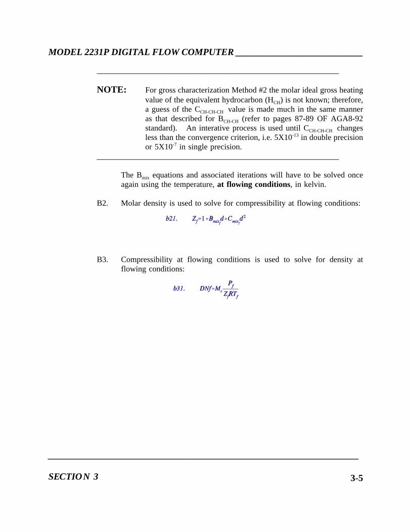
MODEL 2231P DIGITAL FLOW COMPUTER ___________________________
____________________________________________________________
NOTE: For gross characterization Method #2 the molar ideal gross heatingvalue of the equivalent hydrocarbon (HCH) is not known; therefore,a guess of the CCH-CH-CH value is made much in the same manneras that described for BCH-CH (refer to pages 87-89 OF AGA8-92standard). An interative process is used until CCH-CH-CH changesless than the convergence criterion, i.e. 5X10-13 in double precisionor 5X10⁻⁷ in single precision.
____________________________________________________________
The Bmix equations and associated iterations will have to be solved onceagain using the temperature,at flowing conditions, in kelvin.
B2. Molar density is used to solve for compressibility at flowing conditions:
B3. Compressibility at flowing conditions is used to solve for density atflowing conditions:
__________________________________________________________________
SECTION 3 3-5

___________________________MODEL 2231P DIGITAL FLOW COMPUTER
3.3 CALCULATIONS - EACH METER
Equations/calculation methods contained herein are based upon API Manual of PetroleumMeasurement Standards, Chapter 14, Section 3, Part 4. In the event of discrepancies theAPI document shall have precedence.
A. Orifice Diameter
d = OD [1 + PA (TF - PT)]
where,d = corrected orifice diameter, inches at TF
OD = measured orifice diameter, inches at PTPA = plate coefficient of thermal expansionTF = measured fluid temperature, degrees FPT = plate measurement temperature, degrees F
B. Pipe Diameter
D = ID [1 + LA (TF - LT)]
where,D = corrected pipe diameter, inches at TFID = measured pipe diameter, inches at LTLA = pipe coefficient of thermal expansionTF = fluid temperature, degrees FLT = pipe measurement temperature, degrees F
C. Beta
B = d/D
where,B = the computed Beta ratio at TFd = corrected orifice diameter, inches at TFD = corrected pipe diameter, inches at TF
___________________________________________________________________
OPERATION3-6

MODEL 2231P DIGITAL FLOW COMPUTER ___________________________
D. Upstream Static Pressure
P = PF, if TLn is equal to 1
P = (HW/N) + PF, if TLn is equal to 2
where,P = Upstream Static Pressure, PSIATLn = Tap location; 1 = upstream,
2 = downstreamn = meter tube number
PF = Measured pressure, PSIAHW = Measured differential pressure, "H2O (68oF)N = 27.707 for DP "H2O @ 60°F
E. Expansion Factor for Compressible Fluids
Y = 1 - {(0.41 + 0.35 B4)/IE} [HW/(N)]
where,Y = Expansion factorB = Beta as computed in C. aboveIE = Isentropic exponent, operator enteredHW = Measured differential pressure, "H2O (68oF)P = Upstream static pressure per D. aboveN = 27.730 for DP "H2O @ 68°F (DPTYP = 1)N = 27.707 for DP "H2O @ 60°F (DPTYP = 0)
F. Velocity of Approach Factor
EV = 1/(1-B4)1/2
where,EV = Velocity of Approach FactorB = Beta as computed in C. above
__________________________________________________________________
SECTION 3 3-7

___________________________MODEL 2231P DIGITAL FLOW COMPUTER
G. Orifice Flow Coefficients
A0 = 0.5961 S1 = 0.0049A1 = 0.0291 S2 = 0.0433A2 =-0.229 S3 = 0.0712A3 = 0.003 S4 =-0.1145A4 = 2.8 S5 =-0.2300A5 = 0.000511 S6 =-0.0116A6 = 0.021 S7 =-0.5200
S8 =-0.1400
L1 = L2 = 1.0/D, where D is from step B. above
M2 = 2 L2 / (1 - B), where B is from step C. above
Tu = [S2 + S3 e -8.5L1 + S4 e -6.0L1] [B 4/(1 - B4)]
TD = S6 (M2 + S7 M21.3) B1.1
Ts = 0.0, if D > A4
Ts = A3 (1 - B) (A4 - D), if D < A4
Cd0 = A0 + A1 B2 + A2 B8 + Tu + TD + Ts
Cd1 = A5 B0.7 (250)0.7
Cd2 = A6 B4 (250)0.35
Cd3 = S1 B4 B0.8 (4.75)0.8 (250)0.35
Cd4 = (S5 Tu + S8 TD) B0.8 (4.75)0.8
___________________________________________________________________
OPERATION3-8
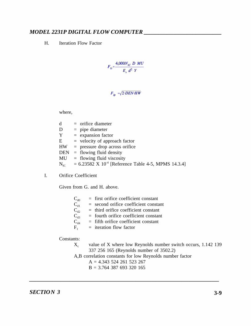
MODEL 2231P DIGITAL FLOW COMPUTER ___________________________
H. Iteration Flow Factor
where,
d = orifice diameterD = pipe diameterY = expansion factorE = velocity of approach factorHW = pressure drop across orificeDEN = flowing fluid densityMU = flowing fluid viscosityNIC = 6.23582 X 10⁻⁴ [Reference Table 4-5, MPMS 14.3.4]
I. Orifice Coefficient
Given from G. and H. above.
Cd0 = first orifice coefficient constantCd1 = second orifice coefficient constantCd2 = third orifice coefficient constantCd3 = fourth orifice coefficient constantCd4 = fifth orifice coefficient constantF1 = iteration flow factor
Constants:Xc value of X where low Reynolds number switch occurs, 1.142 139
337 256 165 (Reynolds number of 3502.2)A,B correlation constants for low Reynolds number factor
A = 4.343 524 261 523 267B = 3.764 387 693 320 165
__________________________________________________________________
SECTION 3 3-9

___________________________MODEL 2231P DIGITAL FLOW COMPUTER
1. Initialize Cd to value at infinite Reynolds number.
Cd = Cd0
2. Calculate X, the ratio of 4,000 to the assumed Reynold’s number,according to the formula:
X = F1 / Cd
3. Calculate the correlation value of Cd, Fc, at the assumed flow, X, and thederivative of the correlation with respect to the assumed value of Cd, Dc,using the following formulae:
If (X < X c) then
Fc = Cd0 + (Cd1 X0.35 + Cd2 + Cd3 X0.8) X0.35 + Cd4 X0.8
Dc = (0.7 Cd1 X0.35 + 0.35 Cd2 + 1.15 Cd3 X0.8) X0.35
+ 0.8 Cd4 X 0.8
ElseFc = Cd0 + Cd1 X0.7 + (Cd2 +Cd3 X0.8)( A - B / X) + Cd4 X0.8
Dc = 0.7 Cd1 X0.7 + (Cd2 + Cd3 X0.8) B/X+ 0.8 Cd3 (A - B/X) X 0.8 + 0.8Cd4 X0.8
4. Calculate the amount to change the guess for Cd, δCd, using the followingformula:
Update the guess for Cd according to:
Cd = Cd - δCd
___________________________________________________________________
OPERATION3-10

MODEL 2231P DIGITAL FLOW COMPUTER ___________________________
5. Repeat Steps 2, 3 and 4 until the absolute value ofδCd is less than0.000005.
6. If the value of X is greater than 1.0then set Cd_felse clear Cd_f
J. Calculation of Volume Flow Rate (Base Conditions)
where,
QHT = hourly flow rate, SCF/HRN1 = 358.927 for DP, "H2O @ 68°F (DPTYP = 1)N1 = 359.072 for DP, "H2O @ 60°F (DPTYP = 0)Cd = discharge coefficient per I. aboveEv = velocity of approach factor per F. aboveY = expansion factor per E. aboved = corrected orifice diameter per A. aboveHw = differential pressure "H2O @ 68oFDNf = flowing density, calculated per AGA-8DNb = base denisty, calculated per AGA-8
__________________________________________________________________
SECTION 3 3-11

___________________________MODEL 2231P DIGITAL FLOW COMPUTER
3.3 OPERATIONAL OVERVIEW
The computer uses a prompting sequence during initial startup. The prompting sequence assiststhe operator with the entering of essential measurement parameters which the computer requiresin determining flow rates and flow totals. Details of the startup procedures are located inSubsection 2.6 of this manual.
Once the initial startup is complete, the operator may access data, enter additional parameters,revise previously entered parameters, and request specific computer actions. The two categoriesof operator control are described below. Refer to Table 3-1, Read Codes and Command Codes.
A. The operator may access or enter specific parameters relating to the data measurement,such as:
1. Cause the computer to display a specific measurement parameter; (i.e.,temperature, flow rate, flow total, etc.).
2. Substitute a selected value for a measured (varying) or a computed value.
Instructions for accessing data are described in detail in Subsection 3.6.
B. The operator may request the computer to perform three types of action. (NOTE: The"enable/disable" switch must be "enabled" and the green "enable" lamp on the front panelmust be ON.
1. Control the display (ON all the time/ON for one minute);
2. Display any out-of-tolerance (error) conditions;
3. Reset flow totals for mass;
Instructions for requesting these actions from the computer are described in Subsection 3.7.
___________________________________________________________________
OPERATION3-12
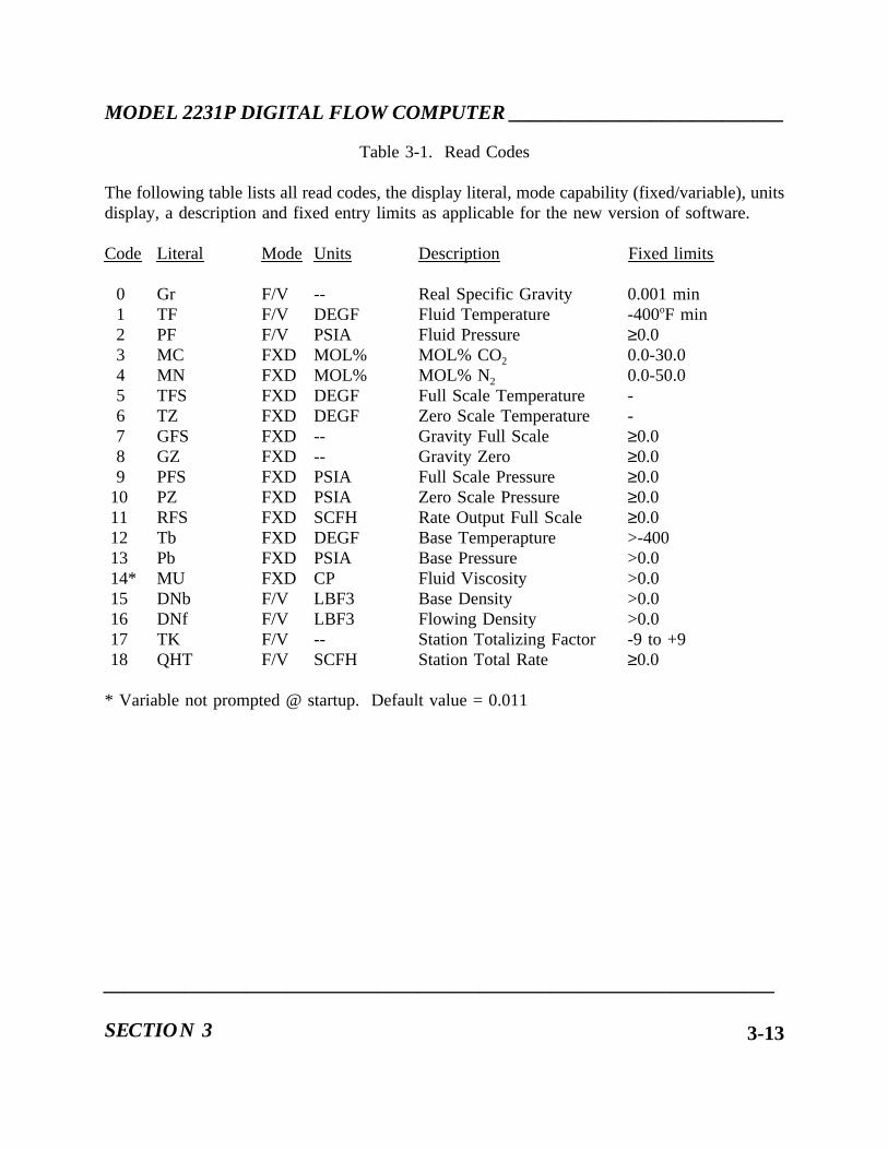
MODEL 2231P DIGITAL FLOW COMPUTER ___________________________
Table 3-1. Read Codes
The following table lists all read codes, the display literal, mode capability (fixed/variable), unitsdisplay, a description and fixed entry limits as applicable for the new version of software.
Code Literal Mode Units Description Fixed limits
0 Gr F/V -- Real Specific Gravity 0.001 min1 TF F/V DEGF Fluid Temperature -400oF min2 PF F/V PSIA Fluid Pressure ≥0.03 MC FXD MOL% MOL% CO2 0.0-30.04 MN FXD MOL% MOL% N2 0.0-50.05 TFS FXD DEGF Full Scale Temperature -6 TZ FXD DEGF Zero Scale Temperature -7 GFS FXD -- Gravity Full Scale ≥0.08 GZ FXD -- Gravity Zero ≥0.09 PFS FXD PSIA Full Scale Pressure ≥0.0
10 PZ FXD PSIA Zero Scale Pressure ≥0.011 RFS FXD SCFH Rate Output Full Scale ≥0.012 Tb FXD DEGF Base Temperapture >-40013 Pb FXD PSIA Base Pressure >0.014* MU FXD CP Fluid Viscosity >0.015 DNb F/V LBF3 Base Density >0.016 DNf F/V LBF3 Flowing Density >0.017 TK F/V -- Station Totalizing Factor -9 to +918 QHT F/V SCFH Station Total Rate ≥0.0
* Variable not prompted @ startup. Default value = 0.011
__________________________________________________________________
SECTION 3 3-13

___________________________MODEL 2231P DIGITAL FLOW COMPUTER
Code Literal Mode Units Description Fixed Limits
19 IE FXD -- Isentropic Exponent >0.020 Dp FXD -- DP Type (0=60°F, 1=68°F) 0,144 DLY FXD MSEC Printer Line Delay >045 DTE FXD -- Day of the Year 1 to 36646 TIM FXD -- Time of Day 0 to 23:5947 DPT FXD HOUR Daily Print Time 00 to 2348 INT FXD HOUR Print Interval 00 to 2349 ID FXD -- 3-Digit Computer ID 00 to 99950 BUD FXD -- Serial Baud Rate 150 to 240051 P01 FXD -- Printed Data Line 1 Valid Code
Through82 P32 FXD -- Printed Data Line 32 Valid Code90 P1S FXD % Premium Level 1 Setpoint 0.0-10091 P2S FXD % Premium Level 2 Setpoint 0.0-10092 BTK FXD -- Premium Base Total Scale Factor -9 to +993 L1K FXD -- Prem-LVL1 Total Scale Factor -9 to +994 L2K FXD -- Prem-LVL2 Total Scale Factor -9 to +997 ADR FXD -- Communications Network Address 0 to 99998 CBD FXD -- Communications Baud Rate 0 to 240099 CPW FXD -- Communications Password 0 to 999
100101 P1 FXD PSIA Matrix Low Pressure ≥0.0102 P2 VAR PSIA Matrix Mid Pressure --103 P3 FXD PSIA Matrix High Pressure >P1104 T1 FXD DEGF Matrix Low Pressure Real #105 T2 VAR DEGF Matrix Mid Pressure --106 T3 FXD DEGF Matrix High Pressure >T1111 DN1 FXD LBF3 Matrix Data Point #1 >0.0112 DN2 FXD LBF3 Matrix Data Point #2 >0.0113 DN3 FXD LBF3 Matrix Data Point #3 >0.0114 DN4 FXD LBF3 Matrix Data Point #4 >0.0115 DN5 FXD LBF3 Matrix Data Point #5 >0.0116 DN6 FXD LBF3 Matrix Data Point #6 >0.0117 DN7 FXD LBF3 Matrix Data Point #7 >0.0118 DN8 FXD LBF3 Matrix Data Point #8 >0.0119 DN9 FXD LBF3 Matrix Data Point #9 >0.0
___________________________________________________________________
OPERATION3-14

MODEL 2231P DIGITAL FLOW COMPUTER ___________________________
Code Literal Mode Units Description Fixed Limits
20n WHn F/V LBHR Line n Hourly Rate >0.021n LFn FXD "H2O Line n Cutoff >0.022n LKn FXD -- Line n Totalize Factor -9 to +923n HFn FXD "H2O Line n DP Full Scale >0.024n IDn FXD INCH Line n Inside Diameter >0.025n ODn FXD INCH Line n Orifice Diameter >0.026n HWn F/V "H2O Line n Differential >0.027n EXn F/V -- Line n Extension >0.028n CDn F/V -- Line n Discharge Coefficient >0.029n Yn F/V -- Line n Expansion Factor >0.030n TLn FXD -- Line n Tap Location 1, 231n PAn FXD -- Line n Plate Alpha None32n PTn FXD DEGF Line n Plate Measure Temp. >0.033n LAn FXD -- Line n Pipe Alpha None34n LTn FXD DEGF Line n Pipe Measure Temp. >0.035n Bn F/V -- Line n Beta >0.036n Pn F/V PSIA Line n Upstream Pressure >0.0
600 BASE BT VAR SCF Premium Base Flow Total --601 PREM L1 VAR SCF Premium Level 1 Flow Total --602 PREM L2 VAR SCF Premium Level 2 Flow Total --
800 RATE LT VAR SCFH Station Total Rate --80n RATE Ln VAR SCFH Line n Hourly Rate --
900 TOTL LT VAR SCF Station Total Volume --90n TOTL Ln VAR SCF Line n Total Volume --
__________________________________________________________________
SECTION 3 3-15

___________________________MODEL 2231P DIGITAL FLOW COMPUTER
Table 3-2. Command Code Listing
CommandCode
Title Action
0 DisplayErrors
Causes the consecutive display of errors by ErrorCode Number
1 DisplayAlways ON
Causes the display to be ON continously
2 DisplayTimeout
Causes the display to be ON temporarilyy, (forone minute) and then be replaced with a blinkingasterisk
5 DisplayConfiguration
Causes the display of the configuration typeentered during startup
15 Clear Print Table Clears all 32 data locations of the Print Table andreplaces with NOT USED
16 Use matrix Causes the computer to switch DEN type to thematrix calculations for DNf
17 Use AGA8 Causes the computer to switch DEN type to theAGA-8, Gross Method 2 for DNf
18 Clear matrix Causes the computer to zero all matrix data.Prompting is initiated via Command Code 16
80n Gross Total Reset Resets the flow totals for the station or line (n)selected
84 Master TotalsReset
Resets all totals for lines, station, premium base,Level 1 and Level 2
86n Premium TotalReset
Resets station premium flow totals for base (n=0),premium Level 1 (n=1) and premium Level 2(n=2)
90 Display A/DChannel 0 inHexadecimal
Causes the display of analog input voltages inhexadecimal form for bench calibration
___________________________________________________________________
OPERATION3-16

MODEL 2231P DIGITAL FLOW COMPUTER ___________________________
through
97 Display A/DChannel 7 inHexadecimal
Causes the display of analog input voltage inhexadecimal form for bench calibration
98 AutomaticCalibration ofZero value toOE4Hexadecimal
Causes the display of the Zero value of referenceanalog circuits
99 AutomaticCalibration ofFull Scale Valueto F1CHexadecimal
Causes the display of the Full Scale value ofreference analog circuits
__________________________________________________________________
SECTION 3 3-17

___________________________MODEL 2231P DIGITAL FLOW COMPUTER
Table 3-3. Error Codes
Code No. Description
0 Analog gravity transducer out of range1 Temperature transducer out of range2 Static pressure transducer out of range3 Line 1 differential pressure transducer under range
through7 Line 5 differential pressure transducer under range8 Temperature out of limit for AGA-89 Pressure out of limit for AGA-8
10 Total volume incremented faster than 25 HZ11 Invalid ratio of pipe I.D. to orifice diameter12 Rate output overscale13 Ratio of line differential to static pressure greater than 414 Specific gravity out of range15 Power failure of watchdog timeout16 Discharge coefficient failure to converge18 Premium base totals incrementing faster than 25 Hz19 Premium Level 1 total incrementing faster than 25 Hz20 Premium Level 2 total incrementing faster than 25 Hz21 Line 1 differential pressure over range
through25 Line 5 differential pressure over range26 P3 entry less than P1 for matrix pressure27 T3 entry less than T1 for matrix temperature28 Static pressure greater than P3 or less than P129 Temperature greater than T3 or less than T130 1 volt calibration error31 5 volt calibration error32 Premium Level 2 set point is less than premium Level 1 set point
___________________________________________________________________
OPERATION3-18

MODEL 2231P DIGITAL FLOW COMPUTER ___________________________
3.4 BASIC KEYBOARD/DISPLAY FUNCTIONS
3.4.1 SELECTING TEMPORARY OR PERMANENT DISPLAY
The display of the computer mnemonics and the operator-entered values are temporary duringstartup. A "power-save" feature is used by the computer to cause the display to remain on fora minute and then be replaced by a blinking asterisk(*). The asterisk indicates that a term orvalue is in the display memory. Recall the term to the display by depressing the DSPY (Display)key.
The temporary display of terms and values can be changed to a permanent display (displayalways ON) after startup.
Depress 1, then CMD to cause the display to remain ON. Depress 2, then CMD to return thedisplay to the "timeout" mode if desired.
3.4.2 VALIDITY CHECKS OF DATA ENTRIES
The computer compares each operator entry with preprogrammed range and format requirements.An unacceptable entry causes the computer to display one of several terms: INVALID, RANGEER, (Range Error), TOO HIGH, TOO LOW or else to repeat the mnemonic term for theparameter. Enter a new, valid parameter (or Read Code number). The range requirements aredescribed in Subsection 3.6 as part of the instructions for accessing data.
__________________________________________________________________
SECTION 3 3-19

___________________________MODEL 2231P DIGITAL FLOW COMPUTER
3.4.3 FUNCTIONS OF SPECIFIC KEYS
The front panel keyboard is arranged in two groups of 12 keys each. The numerical keys, theperiod (.) and the dash or minus (-) on the left are used to enter data values or issue instructionsto the computer through the Read/Command Codes. The group of keys on the right entersfunctions, changes the display, or initiates a computer action. A summary of the key functionsare described below. A more detailed description of the functions are described in subsequentsubsections of this manual.
A. Enter (ENTR) - Inputs into memory any valid data shown on the Alpha/Numeric display.
B. Display (DSPY) - Recalls blanked data to the display when operation is in "displaytimeout" (see Subsection 3.7.1).
C. Numerals, periods (.), and minus sign (-) - For entering numerical data or function codes.
D. Read (READ) - Entering a one- two- or three-digit function numerical code anddepressing READ causes the computer to display the data being used or calculated by thecomputer (see Table 3-1).
E. Fixed (FXD) - Depressing FXD displays data stored in the computer by the operator (e.g.,pressure, temperature, density, etc.). An asterisk displayed with the data identifierindicates that the computer is not currently using the data value for its computations.
F. Variable (VAR) - Depressing VAR displays data from a transducer or a computercalculation. An asterisk displayed with the data identifier indicates that the computer isnot currently using the data for its computations.
___________________________________________________________________
OPERATION3-20

MODEL 2231P DIGITAL FLOW COMPUTER ___________________________
G. Clear (CLR) - Depressing CLR removes entered data values from the data code displayand displays "0.0".
H. Command (CMD) - Entering a one-, two- or three-digit numerical code and depressingCMD causes the computer to execute the specified command (see Table 3-1). Thesecommands include the display of errors and the resetting of totals. (Totals can be resetonly when the green LED is lighted).
I. Up Arrow (↑) - Depressing↑ results in the following actions by the computer:
1. Reading data -↑ causes the computer to backstep to the previous data code. Forexample, if the data corresponding to the Read Code 2 is being viewed, depressing↑ causes the computer to display the data corresponding to Read Code 1.
2. Entering data -↑ indicates to the computer that the data to follow is an exponent(e.g., 2↑ 5 = 2 x 105 = 200,000).
J. Down Arrow (↓) - Depressing↓ reverses the action in 1 (1).
K. Print (PRNT) - Depressing PRNT initiates operator selectable data output to an externalprinter.
__________________________________________________________________
SECTION 3 3-21

___________________________MODEL 2231P DIGITAL FLOW COMPUTER
3.4.4 INDICATORS
Indicators other than the keyboard and LED display consist of three status indicators and anoptional six-digit electromechanical counter on the front panel.
The three colored status indicators show the status condition of the total system. The redindicator is ON when an out-of-tolerance (error) condition exists (e.g., a transmitter over-ranges)and is OFF when the condition ceases to exist.
The amber indicator is ON when the out-of-tolerance condition, which causes the red indicatorto light, is entered by the computer into the error memory list. The amber indicator remainslighted until all error conditions have ceased and the operator has cleared the error memory listas described in Subsection 3.7.2.
The green indicator is ON when the operator entry "enable/disable" switch on PC Board No.1is in the "enable" position. The green indicator being ON indicates that the operator can enteror alter any of the respective measurement parameters when the operator entry "enable/disable"switch, in the "disable" position, causes the computer to display ENABLE at any attempt by theoperator to enter or alter the measurement parameters.
The operational six-digit electromechanical counter on the front panel displays the gross, net, ormass flow total that is selected during the Startup Prompting Sequence.
___________________________________________________________________
OPERATION3-22

MODEL 2231P DIGITAL FLOW COMPUTER ___________________________
3.5 DATA INPUT AND OVERRIDING CONTROLS
The values of the parameters used by the Model 2231P are derived from two sources.
A. Line parameter measurements being monitored by the computer, or calculations performedby the computer, are called variable or VAR values since they change as line orcalculation conditions change.
B. Operator-entered parameter values are called fixed or FXD values since they do notchange.
Some parameters can be only a measured or a calculated value, some can be only an operator-entered value, and some parameters can be either a measured or an operator-entered value. Onlyone value can be actively used in the computer computations. The operator can select and switchto which-ever type of value (measured/calculated or operator-entered) that is to be active.Generally, an operator-entered parameter value is used in lieu of a measured value when aproblem occurs, such as when a line transmitter is malfunctioning and is being removed for repairor replacement.
When the operator enters an access data code (Read Code) into the computer, the display showsthe type parameter value that is currently active. Depress the FXD or VAR key for the alternatevalue type to display the value of the inactive parameter. Note that the inactive value is indicatedby an asterisk (*) located between the parameter mnemonic and the term, FXD or VAR, e.g., "TF* FXD".
__________________________________________________________________
SECTION 3 3-23

___________________________MODEL 2231P DIGITAL FLOW COMPUTER
3.5.1 ENTERING AN OPERATOR - SELECTED VALUE
NOTE: Set the "enable/disable" switch on PC Board No.1 to the "enable" position in orderto enter parameter values. Return the switch to the "disable" position after makingentries to prevent unauthorized or accidental data entries.
Verify the value entered into the computer during startup. Depress the data code accessnumber(s) (Read Code) and then READ. If the measured value is being used by the computer,depress FXD to display the operator-entered value being held inactive. Enter the desired value.Depress ENTR. The display will show OK to indicate that the value is within the acceptablerange, then will show the parameter mnemonic, the units of measurement, and finally the valuethat was entered.
___________________________________________________________________
OPERATION3-24

MODEL 2231P DIGITAL FLOW COMPUTER ___________________________
3.5.2 SWITCHING MEASURED AND OPERATOR ENTERED VALUES
A. Assume that the temperature transducer in the line is suspected of malfunctioning.Assume also that the transducer will need to be removed for repair while the system isflowing.
First examine the transducer output. The Read Code for monitoring a temperature transducer is1 in this example.
Key Display
1 (Basic Read Code) 1READ (Pressed) TF VAR (Variable)READ (Released) DEGF (Units of Measure)
then56.3 (Temperature)
__________________________________________________________________
SECTION 3 3-25

___________________________MODEL 2231P DIGITAL FLOW COMPUTER
B. Next, assume that the temperature for the line is known to be approximately 78 degrees(the VAR 56.3 degree temperature reading verifies that the transducer output isinaccurate) so a 78 degree temperature will need to be entered into the computer as aFXD value for the computer to use in its calculations until the defective transducer canbe returned to service.
Examine the current inactive FXD value:
Key Display
FXD (Pressed) TF * FXD (Fixed)FXD (Released) DEGF (Units of Measure)
then0.00
C. The asterisk (*) between TF and FXD indicates that this value is not active (not beingused by the computer for flow computations). Instead, the computer is using the 56.3VAR output from the defective transducer. The current FXD value is "0.00".
Enter a new FXD value of 78 degrees
Key Display
7 78 78ENTR TF * FXD (Fixed)
DEGF (Units of Measure)then78.0
___________________________________________________________________
OPERATION3-26

MODEL 2231P DIGITAL FLOW COMPUTER ___________________________
D. Switch the value of the temperature from VAR to FXD. Depress ENTR again.
Key Display
ENTR (Pressed) TF FXDENTR (Released) OK (Valid Entry)
thenDEGF (Units of Measure)then78.0
The value being displayed (VAR or FXD) is entered into the computer calculations by depressingENTR. (In the example above, FXD was the last value type displayed before depressing ENTRto enter the 78 degrees, so ENTR was depressed twice; once to enter the temperature as theinactive FXD value a second time to enter the inactive FXD value into the computer as the activevalue).
Note that the display of TF FXD contains no asterisk, signifying that the FXD value is now theactive value being used for flow computations.
E. Next, assume that the transducer is repaired or replaced and is ready to be returned to use.Switch the temperature from the active FXD value to the inactive VAR value. Enter theappropriate Read Code (1 in this example) to view the value being used. The display willshow that it is the 78 degree FXD value entered previously.
Next, view the current VAR value:
KEY DISPLAY
VAR (Pressed) TF VAR (Variable)VAR (Released) DEGF (Units of Measure)
then76.4
Note that for the example, the VAR value is now 76.4 degrees and the asterisk signifies that thevalue is not active (not being used for flow computation).
__________________________________________________________________
SECTION 3 3-27

___________________________MODEL 2231P DIGITAL FLOW COMPUTER
Depress ENTR to make VAR the active value:
KEY DISPLAY
ENTR TF VAR (Variable)thenOKthenDEGF (Units of Measure)then76.4
OK signifies that the entry of the VAR value was accepted and the absence of the asteriskindicated that the VAR value is now being used for flow computations.
___________________________________________________________________
OPERATION3-28

MODEL 2231P DIGITAL FLOW COMPUTER ___________________________
3.6 DATA ACCESS
As stated in the Operational Overview part of this section of the manual, the operator may accessdata in the computer for one or two type actions:
A. To display a specific measurement parameter, flow rate or flow totals;
B. To substitute an operator-entered (FXD) value for a measured (VAR) value as describedin Subsection 3.5 (set the "enable/disable" switch to the "enable" position).
Operator accessible data are described below by groups as they apply to different operationalfunctions. A numerical listing of the related access codes (Read Codes) appear in Table 3-1.A code-by-code description of the Read Codes appears in Appendix B at the back of this manual.
Data request group descriptions appear in the following order, starting in Subsection 3.6.1:
A. Transducer Scaling.B. Measurements.C. Operator Entered Data ConstantsD. Computer Calculated Variables.E. Output Scaling.
Other operational functions are described elsewhere in this manual. Refer to the Table ofContents to determine their location.
__________________________________________________________________
SECTION 3 3-29

___________________________MODEL 2231P DIGITAL FLOW COMPUTER
3.6.1 TRANSDUCER SCALING
Read Codes for transducer scaling will display the full scale and zero values that are used by thecomputer to scale measured input signals from the respective transducers. Transducer scalingis displayed only as FXD values. Transducer scaling is displayed only as FXD values. Thevalues may be changed by the operator by keying in the new values and depressing ENTR.
A. Temperature Transducer Full Scale (TFS) - Read Code 5Temperature Transducer Zero (TZ) - Read Code 6
Full scale and zero temperature values, used by the computer to scale input signals fromthe temperature transducer, are displayed by using Read Codes 5 and 6. Temperature isdisplayed in degrees Fahrenheit.
B. Gravitometer Full Scale (GFS) - Read Code 7Gravitometer Zero (GZ) - Read Code 8
Full scale and zero gravity values, used by the computer to scale input signals from theanalog gravitometer, are displayed by using Read Codes 7 and 8. Gravity values aredisplayed in SGU (Specific Gravity Units).
C. Static Pressure Transducer Full Scale (PFS) - Read Code 9Static Pressure Transducer Zero (PZ) - Read Code 10
Full scale and zero pressure values, used by the computer to scale input signals from thepressure transducer, are displayed by using Read Codes 9 and 10. Pressure is displayedin PSIA.
D. Line Differential Pressure Full Scale (HFn) - Read Code 23n
The full scale line differential pressure, used by the computer to scale pressure differentialin line number (n), is displayed by using Read Code 23n. Pressure is displayed in inchesof water. FXD values greater than zero are acceptable.
NOTE: Refer to Field Wiring Diagram, DE-9413, for the definition of the transducer perconfiguration selected.
___________________________________________________________________
OPERATION3-30

MODEL 2231P DIGITAL FLOW COMPUTER ___________________________
3.6.2 MEASUREMENTS
Read Codes for measurements display measured input values used by the computer in calculationof the flow rates and flow totals. Measurements are displayed as VAR values. The values maybe changed to a FXD value by the operator. Refer to Subsection 3.5.2.
A. Specific Gravity (G) - Read Code 0
The measured specific gravity value, used by the computer to calculate flow rates andflow totals is displayed by using Read Code 0. The specific gravity is displayed inSpecific Gravity Units (SGU). FXD values greater than 0.001 are acceptable.
B. Temperature (TF) - Read Code 1
The measured temperature value, used by the computer to calculate flow rates and flow totals,is displayed by using Read Code 1. The display is in degrees Fahrenheit. FXD values above -400 degrees Fahrenheit are acceptable.
C. Static Pressure (PF) - Read Code 2
The measured static pressure value, used by the computer to calculate flow rates and flowtotals, is displayed by using Read Code 2. The pressure is displayed in PSIA. FXDvalues above 0.0 PSIA are acceptable.
D. Line Differential Pressure (HWn) - Read Code 26n
The pressure differential, used by the computer to calculate line flow rates and totals, isdisplayed by Read Code 26n for the line selected (n). Pressure is displayed in inches ofwater. FXD values between 0 and 1000 are acceptable for testing purposes only.
__________________________________________________________________
SECTION 3 3-31

___________________________MODEL 2231P DIGITAL FLOW COMPUTER
3.6.3 OPERATOR-ENTERED DATA CONSTANTS
Read Codes for operator-entered data constants display the values of those data which generallyremain constant. Data such as orifice diameter, line ID, and line tap location are displayed asFXD values. The values may be changed by the operator by keying in new values anddepressing ENTR.
NOTE: If DENTYP = is 1 or if Command Code 16 is active, MOL%CO2 or MOL%N2
values are not used by the computer for calculations. Instead, the matrixcalculated density value is derived from live TF and PF inputs.
A. Molecular Percentage of CO2 (MOL% CO2) - Read Code 3
The molecular percentage of carbon dioxide in the product, used by the computer for calculatingproduct flow rates and totals, is displayed by using Read Code 3. The value is displayed inpercent. FXD values between 0.0 and 30 percent are acceptable.
B. Molecular Percentage of N2 (MOL% N2) - Read Code 4
The molecular percentage of nitrogen in the product, used by the computer for calculatingproduct flow rates and totals, is displayed by using Read Code 4. The value is displayed inpercent. FXD values between 0.0 and 50 percent are acceptable.
___________________________________________________________________
OPERATION3-32

MODEL 2231P DIGITAL FLOW COMPUTER ___________________________
C. Base Temperature (TB) - Read Code 12
The base temperature of the product being measured is displayed by using Read Code 12. FXDvalues above -400 are acceptable.
D. Base Pressure (PB) - Read Code 13
The base pressure of the product being measured is displayed by using Read Code 13. FXDvalues greater than 0.0 are acceptable.
E. Fluid Viscosity (MU) - Read Code 14
The fluid viscosity value variable is not prompted at start up, but defaults to 0.011 CP. Thecurrent value can be display using Read Code 14. Values must be greater than 0.0.
F. Isentropic Exponent (IE) - Read Code 19
The isentropic exponent may be displayed by using Read Code 19. This is an operator-enteredvalue greater than 0.0.
G. Thermal Expansion Factor (FA) - Read Code 20
The thermal expansion factor, used by the computer to adjust the line flow calculations forchanges from the bored orifice temperature, is displayed by using Read Code 20. FXD valuesfrom 0.0 and above may be entered for testing only. Entering FXD values affect flow totals ifthe computer is on line.
__________________________________________________________________
SECTION 3 3-33

___________________________MODEL 2231P DIGITAL FLOW COMPUTER
H. Premium Level 1 Set Point (P1S) - Read Code 90
The premium level 1 set point, used by the computer to calculate base and premium level 1 totalflow, is displayed by using Read Code 90. The value is displayed in percent of Flow Rate FullScale (RFS - Read Code 11). FXD values between 0.0 and 100 are acceptable. Entering a 0.0value will disable all premium flow total calculations.
I. Premium Level 2 Set Point (P2S) - Read Code 91
The premium level 2 set point, used by the computer to calculate premium level 1 and premiumlevel 2 total flow, is displayed by using Read Code 91. The value is displayed in percent ofFlow Rate Full Scale (RFS - Read Code 11). FXD values between 0.0 and 100 that are greaterthan Premium Level 1 Set Point (P1S) are acceptable. Entering a 0.0 value will disable onlypremium level 2 flow totals.
NOTE: The following Read Code value entries are used by the computer to calculate FPVonly if a 1 is entered for the mnemonic DENTYPE=, or if Command Code 16 isactive:
Read CodeNumber
MnemonicI.D.
15101103104106111112113114115116117118119
DNBP1P3T1T3DN1DN2DN3DN4DN5DN6DN7DN8DN9
___________________________________________________________________
OPERATION3-34

MODEL 2231P DIGITAL FLOW COMPUTER ___________________________
J. Matrix Low Pressure (P1) - Read Code 101
The matrix low pressure point, used by the computer for the calculation of FlowingCompressibility (ZF - Read Code 96), is displayed by using Read Code 101. FXD values greaterthan zero should be acceptable. Matrix low pressure is displayed in PSIA.
K. Matrix High Pressure (P3) - Read Code 103
The matrix high pressure point, used by the computer for the calculation of FlowingCompressibility (ZF - Read Code 96), is displayed by using Read Code 103. FXD values greaterthan Matrix Low Pressure (P1) should be acceptable. Matrix high pressure is displayed in PSIA.
L. Matrix Low Temperature (T1) - Read Code 104
The matrix low temperature point, used by the computer for the calculation of FlowingCompressibility (ZF - Read Code 96), is displayed by using Read Code 104. FXD values shouldbe acceptable. Matrix low temperature is displayed in DEGF.
M. Matrix High Temperature (T3) - Read Code 106
The matrix high temperature point, used by the computer for the calculation of FlowingCompressibility (ZF - Read Code 96), is displayed by using Read Code 106. FXD real valuesgreater than Matrix Low Temperature (T1) should be acceptable. Matrix high temperature isdisplayed in DEGF.
__________________________________________________________________
SECTION 3 3-35

___________________________MODEL 2231P DIGITAL FLOW COMPUTER
N. Matrix Data Point 1 (DN1) - Read Code 111
The matrix density value at data point 1 (for T1 and P1) is displayed by using Read Code 111.FXD positive values greater than zero should be acceptable.
O. Matrix Data Point 2 (DN2) - Read Code 112
The matrix density value at data point 2 (for T1 and P2) is displayed by using Read Code 112.FXD positive values greater than zero should be acceptable.
P. Matrix Data Point 3 (DN3) - Read Code 113
The matrix density value at data point 3 (for T1 and P3) is displayed by using Read Code 113.FXD positive values greater than zero should be acceptable.
Q. Matrix Data Point 4 (DN4) - Read Code 114
The matrix density value at data point 4 (for T2 and P1) is displayed by using Read Code 114.FXD positive values greater than zero should be acceptable.
R. Matrix Data Point 5 (DN5) - Read Code 115
The matrix density value at data point 5 (for T2 and P2) is displayed by using Read Code 115.FXD positive values greater than zero should be acceptable.
S. Matrix Data Point 6 (DN6) - Read Code 116
The matrix density value at data point 6 (for T2 and P3) is displayed by using Read Code 116.FXD positive values greater than zero should be acceptable.
___________________________________________________________________
OPERATION3-36

MODEL 2231P DIGITAL FLOW COMPUTER ___________________________
T. Matrix Data Point 7 (DN7) - Read Code 117
The matrix density value at data point 7 (for T3 and P1) is displayed by using Read Code 117.FXD positive values greater than zero should be acceptable.
U. Matrix Data Point 8 (DN8) - Read Code 118
The matrix density value at data point 8 (for T3 and P2) is displayed by using Read Code 118.FXD positive values greater than zero should be acceptable.
V. Matrix Data Point 9 (DN9) - Read Code 119
The matrix density value at data point 9 (for T3 and P3) is displayed by using Read Code 119.FXD positive values greater than zero should be acceptable.
W. Line Cutoff (LFn) - Read Code 21n
If the line pressure in inches of water falls below this operator-entered value, the computer forcesQH = 0.0, and does not record flow totals. This avoids integration of volume during periods ofno flow if the transmitter zero increases due to ambient temperature or other environmentalinfluences.
X. Line Inside Diameter (IDn) - Read Code 24n
The line inside diameter, used by the computer for calculating line flow, is displayed for linenumber (n) by using Read Code 24n. The value is displayed in inches. FXD values between0.0011 and 50.0 inches are acceptable.
Y. Line Orifice Diameter (ODn) - Read Code 25n
The line orifice diameter, used by the computer for calculating flow, is displayed for line number(n) by using Read Code 25n. The value is displayed in inches. FXD values between 0.0011 and40 inches are acceptable.
__________________________________________________________________
SECTION 3 3-37

___________________________MODEL 2231P DIGITAL FLOW COMPUTER
Z. Line Tap Location (TLn) - Read Code 30n
The location of the line tap for the selected line number (n) is displayed by using Read Code30n. The display will show 1 (upstream) or 2 (downstream).
AA. Ratio of Specific Heats (Kn) - Read Code 19
The line ratio of specific heats, used by the computer to adjust the calculated line ExpansionFactor (Yn) in line number (n), is displayed by using Read Code 19. FXD values greater thanzero are acceptable. A default value of 1.3 for natural gas is used by the computer unless theoperator enters a different value.
___________________________________________________________________
OPERATION3-38

MODEL 2231P DIGITAL FLOW COMPUTER ___________________________
3.6.4 COMPUTER CALCULATED VARIABLES
Read Codes for the computer calculated variables cause the display of the values computed fromvarious other calculations. All computer calculated variables are displayed as VAR values.
A. Base Density (DNB) - Read Code 15
The mass density at base conditions may be displayed by using Read Code 15. The base densityis calculated by the computer in accordance with A.G.A. 8-1992 Gross Method #2. Positivevalues are acceptable. Fixed value is also the matrix entered DNB.
B. Flowing Density (DNF) - Read Code 16
The density at flowing conditions may be displayed by using Read Code 16. The density atflowing conditions is calculated by the computer in accordance with A.G.A. 8-1992 GrossMethod #2. Positive values are acceptable.
C. Total Hourly Flow Rate (QHT) - Read Code 18
The current total hourly flow rate may be displayed by using Read Code 18. The rate isdisplayed in SCFH. FXD values from 0.0 and above may be entered for testing purposes only.FXD value entries will affect flow totals if the computer is on line.
D. Matrix Mid Pressure (P2) - Read Code 102
The matrix mid pressure point, calculated by the computer based upon the matrix pressure pointsfor P1 and P3, is displayed by using Read Code 102. FXD value entries are accepted but arenot used by the computer; the computer uses only the VAR value. Matrix midpoint pressure isdisplayed in PSIA. This matrix value is used by the computer only if a 1 is entered for themnemonic DENTYP =, or if Command Code 16 is active.
__________________________________________________________________
SECTION 3 3-39

___________________________MODEL 2231P DIGITAL FLOW COMPUTER
E. Matrix Mid Temperature (T2) - Read Code 105
The matrix mid temperature point, calculated by the computer based upon the matrix temperaturepoints for T1 and T3, is displayed by using Read Code 105. FXD value entries are accepted butare not used by the computer; the computer uses only the VAR value. Matrix midpointtemperature is displayed in DEGF. This matrix value is used by the computer only if a 1 isentered for the mnemonic DENTYP =, or if Command Code 16 is active.
F. Line Hourly Flow Rate (QHn) - Read Code 20n
The hourly flow rate of a selected line number (n) may be displayed by using Read Code 20n.The rate is displayed in SCFH. FXD values from 0.0 and above may be entered for testing only.FXD value entries will affect flow totals if the computer is on line.
G. Line Extension (EXn) - Read Code 27n
The extension factor for a selected line number (n), used by the computer to calculate theReynolds factor for the line, may be displayed by using Read Code 27n. The line extensiondisplay is the square root of (HWn x PF). FXD values of any positive real number can beentered for test purposes only. FXD value entries will affect flow totals if the computer is online.
H. Line Discharge Coefficient (CDn) - Read Code 28n
The discharge coefficient for a selected line number (n), used by the computer to calculate flowtotals, may be displayed by using the Read Code 28n. FXD values determined from A.G.A. 3greater than 0.0 are acceptable.
___________________________________________________________________
OPERATION3-40

MODEL 2231P DIGITAL FLOW COMPUTER ___________________________
I. Line Expansion Factor (Yn) - Read Code 29n
The expansion factor for a selected line number (n) may be displayed by using Read Code 29n.The computer calculates the expansion factors in accordance with A.G.A. 3. FXD valuesdetermined from A.G.A 3 are acceptable. Typical values are between 0.87 and 1.04.
J. Premium Base Flow Total (BASE BT) - Read Code 600
Read Code 600 displays the station premium base flow total. Premium base flow total isdisplayed as a VAR value. A typical premium base flow total Read Code entry and display isshown below:
Key Display
6 60 (Read Code) 600 600READ (Depressed) BASE BT (Base unit of measure)READ (Released) SCF E0
then (A power of ten (totalizing factor) that is00000000 multiplied by the base unit of measure, i.e.,
SCF times 10 to the zero power (E0) = SCFtimes 1.)
__________________________________________________________________
SECTION 3 3-41

___________________________MODEL 2231P DIGITAL FLOW COMPUTER
K. Premium Level 1 Flow Total (PREM L1) - Read Code 601
Read Code 601 displays the station flow total of premium level 1 that has exceeded the PremiumLevel 1 Set Point (P1S - Read Code 90). premium level 1 flow total is displayed as a VARvalue.
A typical premium level 1 flow total Read Code entry and display as shown below:
Key Display
6 60 (Read Code) 601 (Level 1) 601 (Premium level 1)READ (Depressed) PREM L1 (Base unit of measure)READ (Released) SCF E0
then (A power of ten (totalizing factor) that is00000000 multiplied by the base unit of measure, i.e.,
SCF times 10 to the zero power (E0) = SCFtimes 1.)
___________________________________________________________________
OPERATION3-42

MODEL 2231P DIGITAL FLOW COMPUTER ___________________________
L. Premium Level 2 Flow Total (PREM L2) - Read Code 602
Read Code 602 displays the station flow total of premium level 2 that has exceeded the PremiumLevel 2 Set Point (P2S - Read Code 91). Premium level 2 flow total is displayed as a VARvalue.
A typical premium level 2 flow total Read Code entry and display is shown below:
Key Display
6 60 (Read Code) 602 (Level 2) 602 (Premium level 2)READ (Depressed) PREM L2 (Base unit of measure)READ (Released) SCF E0
then (A power of ten (totalizing factor) that is00000000 multiplied by the base unit of measure, i.e.,
SCF times 10 to the zero power (E0) = SCFtimes 1.)
__________________________________________________________________
SECTION 3 3-43

___________________________MODEL 2231P DIGITAL FLOW COMPUTER
M. Total Hourly Flow (RATE Ln) - Read Code 80n
Read Code 80n is used to display the total hourly flow rate as measured through the line selectedwhere n = 1, 2, 3, 4, or 5, or,through the station (n=0). Flow rate is displayed as a VAR value.
A typical total hourly flow rate Read Code entry and display is shown below:
Key Display
8 80 (Basic Read Code) 801 (Line No.) 802 (Premium level 2)READ (Depressed) RATE L1 (Base unit of measure)READ (Released) SCFH E0
then (A power of ten (totalizing factor) that is00000000 multiplied by the base unit of measure, i.e.,
SCF times 10 to the zero power (E0) = SCFtimes 1.)
Line and StationIdentification
LT = StationL1 = Line 1L2 = Line 2L3 = Line 3L4 = Line 4L5 = Line 5
___________________________________________________________________
OPERATION3-44

MODEL 2231P DIGITAL FLOW COMPUTER ___________________________
N. Total Flow (TOTAL Ln) - Read Code 90n
Read Code 90n displays flow totals through the selected line number (n), where n=line 1, 2, 3,4, or 5, or, through the station (n=0). Flow totals are displayed as a VAR value.
A typical flow total Read Code entry and display is shown below:
Key Display
9 90 (Basic Read Code) 901 (Line No.) 902 (Premium level 2)READ (Depressed) TOTAL L1 (Base unit of measure)READ (Released) SCF E0
then (A power of ten (totalizing factor) that is00000000 multiplied by the base unit of measure, i.e.,
SCF times 10 to the zero power (E0) = SCFtimes 1.)
Line and StationIdentification
LT = StationL1 = Line 1L2 = Line 2L3 = Line 3L4 = Line 4L5 = Line 5
__________________________________________________________________
SECTION 3 3-45

___________________________MODEL 2231P DIGITAL FLOW COMPUTER
3.6.5 OUTPUT SCALING
Read Codes are used to display the analog output scaling for the totalizing factor for the stationand the totalizing factor for the lines.
All output scaling is displayed only as FXD values. The operator may change the scaling ratesand totalizing factors by keying in the values and depressing ENTR.
A. Flow Rate Full Scale (RFS) - Read Code 11
The full scale flow rate, related to the analog volume rate output, may be displayed by usingRead Code 11. The rate is displayed in SCFH. Only FXD values are accepted by the computer.
B. Station Totalizing Factor (TK) - Read Code 17
A power of ten multiplier (the totalizing factor) that is being applied to the station totalizationis displayed with the use of Read Code 17. FXD entry of integer exponent values between -9and +9 are acceptable (refer to Subsection 2.6.3.1 for details pertaining to totalizer scaling). Thevalue may be changed by the operator keying in the values and depressing ENTR.
If no exponent is entered to factor the totals, the computer uses a totalizing factor of 10o.
C. Premium Base Total Scale Factor (BTK) - Read Code 92
A power of ten multiplier (the totalizing factor) that is being applied to the station Premium Basetotalization (Read Code 600) is displayed with the use of Read Code 92. The FXD entry ofinteger exponent values between -9 and +9 is acceptable (refer to Subsection 2.6.3.1 for detailspertaining to totalizer scaling). The value may be changed by the operator keying in the valuesand depressing ENTR.
If no exponent is entered to factor the premium base total, the computer uses a totalizing factorof 10o.
___________________________________________________________________
OPERATION3-46

MODEL 2231P DIGITAL FLOW COMPUTER ___________________________
D. Premium Level 1 Total Scale Factor (L1K) - Read Code 93
A power of ten multiplier (the totalizing factor) that is being applied to the station PremiumLevel 1 totalization (Read Code 601) is displayed with the use of Read Code 93. The FXD entryof integer exponent values between -9 and +9 is acceptable (refer to Subsection 2.6.3.1 for detailspertaining to totalizer scaling). The value may be changed by the operator keying in the valuesand depressing ENTR.
If no exponent is entered to factor the premium level 1 total, the computer uses a totalizing factorof 10o.
E. Premium Level 2 Total Scale Factor (L2K) - Read Code 94
A power of ten multiplier (the totalizing factor) that is being applied to the station PremiumLevel 2 totalization (Read Code 602) is displayed with the use of Read Code 94. The FXD entryof integer exponent values between -9 and +9 is acceptable (refer to Subsection 2.6.3.1 for detailspertaining to totalizer scaling). The value may be changed by the operator keying in the valuesand depressing ENTR.
If no exponent is entered to factor the premium level 2 total, the computer uses a totalizing factorof 10o.
F. Line Totalizing Factor (LKn) - Read Code 22n
A power of ten multiplier (the totalizing factor) that is being applied to the total of the selectedline (n), is displayed with the use of Read Code 22n. The operator may enter exponent valuesbetween -9 and +9 is acceptable (refer to Subsection 2.6.3.1 for details pertaining to totalizerscaling). Key in the values and depress ENTR.
If no exponent is entered to factor the totals, the computer uses a totalizing factor of 10o.
__________________________________________________________________
SECTION 3 3-47

___________________________MODEL 2231P DIGITAL FLOW COMPUTER
3.7 COMPUTER ACTION REQUESTS
As stated in the Operational Overview portion of Section 3 of this manual, the operator maycause the computer to perform one of four types of action:
A. Controlling the display (ON all the time/ON for one minute);
B. Switching the DENTYP to be used by the computer;
C. Calling for the computer to display any out-of-tolerance (error) conditions; and,
D. Resetting flow totals.
For user convenience, the computer actions are described below by groups as they apply todifferent operational functions. A numerical listing of the Command Codes appear in Table 3-1.A code-by-code description appears in the appendix at the back of this manual. Set the"enable/disable" switch to the "enable" position to perform all actions.
The group descriptions appear in the following order, starting in Subsection 3.7.1:
A. Operational Actions
B. Diagnostic Aid Actions
C. Parameter Display Actions
D. Clearing Actions
Other operational functions are described elsewhere in this manual. Refer to the Table ofContents to determine their location.
___________________________________________________________________
OPERATION3-48

MODEL 2231P DIGITAL FLOW COMPUTER ___________________________
3.7.1 OPERATIONAL ACTIONS
Command Codes pertaining to the computer operation are used to change or control the computeroperation after initial startup.
A. Display Always ON - Command Code 1Display Timeout - Command Code 2
Command Code 1 causes the display to be ON continuously. Command Code 2 causes thedisplay to be ON for one minute and then to go off with the displayed terms replaced by ablinking asterisk(*).
B. Use Entered Density Data - Command Code 16
Command Code 16 causes the computer to switch DENTYP = from the FPV calculation to thematrix calculation. If different matrix pressure, temperature, and density points are desired,activate Command Code 18 first, then activate Command Code 16 for the computer to promptthrough matrix points P3, P1, T3, T1, and DN1 - DN9 and for DNB. Each time CMD 16 isexecuted, the computer will prompt for DNB input.
C. Use Instrument Calculated FPV for Natural Gas - Command Code 17
Command Code 17 instructs the computer to compute FPV in accordance with A.G.A. 8. It isignored if DN TYPE = is already a zero.
D. Clear Matrix Density Data - Command Code 18
Command Code 18 causes the computer to set up matrix points P3, P1, T3, T1, DN1 - DN9 andDNB for prompting when Command Code 18 is followed with Command Code 16.
__________________________________________________________________
SECTION 3 3-49

___________________________MODEL 2231P DIGITAL FLOW COMPUTER
3.7.2 DIAGNOSTIC AID ACTIONS
Diagnostic Aid Actions enable the operator to visually monitor or verify suspected problem areas.All of the Diagnostic Aids, except Command Code 0, are used only in bench calibrations andtests.
A. Display Errors - Command Code 0
The red status indicator on the front panel is ON when an out-of-tolerance (error) conditionoccurs, and turns OFF when the error condition ends. Refer to Error Code Table 2-5 for possibleerror causes and solutions.
The amber status indicator on the front panel is ON to indicate that the error condition has beenentered into the computer error memory, even if the error no longer exists. The amber indicatorremains ON until the operator clears the memory list.
Command Code 0 displays the list of errors in memory in numerical sequence. Depress CLRto acknowledge and clear an error from the memory list. The computer automatically advancesthe display to the next error number.
When the error conditions no longer exist, and when all of the error codes in the memory listhave been acknowledged, the amber status light turns OFF.
B. Display A/D Channel 0 in Hexadecimal - Command Code 90Display A/D Channel 1 in Hexadecimal - Command Code 91Display A/D Channel 2 in Hexadecimal - Command Code 92Display A/D Channel 3 in Hexadecimal - Command Code 93Display A/D Channel 4 in Hexadecimal - Command Code 94Display A/D Channel 5 in Hexadecimal - Command Code 95Display A/D Channel 6 in Hexadecimal - Command Code 96Display A/D Channel 7 in Hexadecimal - Command Code 97
Command Codes 90 through 97 display analog input voltages in hexadecimal form for benchcalibrations and software diagnostic testing. They are not applicable for field use.
___________________________________________________________________
OPERATION3-50

MODEL 2231P DIGITAL FLOW COMPUTER ___________________________
C. Automatic Calibration of Zero Value to 0E4 Hexadecimal - Command Code 98Automatic Calibration of Full Scale Value to F1C Hexadecimal - Command Code 99
D. Memory Diagnostics for the Model 2231P Computer
The Model 2231P contains two types of memory circuits. RAM (Random Access Memory)integrated circuit (IC) chips are used to store the calculated rates and totals, as well as other datawhich changes value. PROM (Programmable Read Only Memory) IC’s are used to permanentlyhold the unchanging program instructions that calculate the data values stored in RAM.
The Model 2231P performs diagnostic checks on both the RAM and the PROM memories toinsure the reliability of the calculations performed and the safe storage of the resulting data. Ifa memory failure occurs, the system halts all flow calculations because their reliability would beuncertain. A diagnostic message is displayed on the front panel in the form MEM XX00 whereXX is the starting address of the memory IC chip which has failed. The table below shows therelation of the address displayed to actual IC chips numbered on the PC Board assemblydrawings in Section 6. Be sure to refer to the correct drawing for the affected board.
The RAM memory diagnostic check is run during the initialize sequence, after the operator hassimultaneously pressed both the CMD and CLR keys to clear all memory and start aconfiguration (CNFG) prompting sequence.
The PROM memory diagnostic check is run every ten seconds during normal use of thecomputer.
The diagnostic test runs successfully even if all RAM memory fails and nearly all PROMmemory fails. All that is required is that the small section of PROM memory containing thediagnostic routines be operable. If this portion of memory fails, the system "watchdogs"(causing the indicator lights on the front panel to blink) and halts further processing.
Even though the system ceases to calculate rates and totals upon detecting a memory failure, thediagnostic test continues to run. If the memory checks out good on the next pass, the system isallowed to resume processing as if a temporary power failure has occurred.
In the event of PROM memory failure, all measurement data is maintained in RAM memory.To access this information, correct the PROM memory problem by replacing the defective chip.
__________________________________________________________________
SECTION 3 3-51

___________________________MODEL 2231P DIGITAL FLOW COMPUTER
TABLE 3-4. Memory Types
ADDRESSEDDISPLAYED
0<0
100020004000
7000740078007C00
80009000A000
TYPE OFMEMORY
PROM
PROMPROMPROM
RAMRAMRAMRAM
PROMPROMPROM
ON PCBOARD NO.
1
111
1111
222
I CNO.
U12 (Failurecauseswatchdog)U3U13U14
U19 AND U20U24 AND U25U31 AND U32U37 AND U38
U11U12U15
___________________________________________________________________
OPERATION3-52

MODEL 2231P DIGITAL FLOW COMPUTER ___________________________
3.7.3 PARAMETER DISPLAY ACTIONS
The parameter display Command Codes used to display the values of parameters set into thecomputer during initial startup.
A. Display Configuration - Command Code 5
The type configuration entered by the operator during initial startup may be displayed with theuse of Command Code 5. The display appears as shown below:
DENTYP zthenCFG x y
where:
x = Number of meter tubes and their stack configurationy = Tap Type being used
PT for Pipe TapFT for Flange Tap
z = DENTYP being used0 for Instrument Calculated AGA 8 FPV1 for Entered Density Data
The configuration type can be changed either by erasing all start up parameters from memory andrepeating the Start Up Prompting Sequence as described in Subsection 2.6, or by using CommandCodes 16, 17, and 18 to switch DENTYP’s to be used by the computer.
Erase the startup parameters by simultaneously depressing CMD and CLR.
B. Display Calculation Time - Command Code 8
The length of the calculation currently being performed by the computer is displayed by usingCommand Code 8. The display is in seconds.
__________________________________________________________________
SECTION 3 3-53

___________________________MODEL 2231P DIGITAL FLOW COMPUTER
3.7.4 CLEARING ACTIONS
A. Total Reset - Command Code 80n
The mass flow totals related to the selected number (n) where n = 1, 2, 3, 4, 5, or, to thestation(n=0), are reset by the use of Command Code 80n. A typical line total reset is entered anddisplayed as in the following example:
Key Display
8 80 (Basic Command 80
Code)1 (Line No.) 801 Total ResetCMD Clear L1 Line 1ENTR OK
thenREADY
Line and StationIdentification
LT = StationL1 = Line 1L2 = Line 2L3 = Line 3L4 = Line 4L5 = Line 5
B. Master Totals Reset - Command Code 84
Command Code 84 simultaneously resets flow totals for all lines; the station and station premiumbase; level 1 and level 2.
___________________________________________________________________
OPERATION3-54

MODEL 2231P DIGITAL FLOW COMPUTER ___________________________
C. Premium Total Reset - Command Code 86n
The flow totals related to the station base (n=0), station premium level 1 (n=1), or stationpremium level 2 (n=2), are reset by the use of Command code 86n. A typical station premiumtotal reset is entered and displayed as in the following example:
Key Display
8 80 (Basic Command 86
Code)0 (Premium Type) 860 (Total Reset)CMD Clear BT (Premium Base)ENTR OK
thenREADY
Station Premium Type Identifications
BT = Station Premium Base TotalB1 = Station Premium Level 1 TotalB2 = Station Premium Level 2 Total
__________________________________________________________________
SECTION 3 3-55

___________________________MODEL 2231P DIGITAL FLOW COMPUTER
3.8 SERIAL OUTPUT FOR PRINTING
The Serial Output Option allows the operator to output the process information stored incomputer memory to an off-line printer in serial form.
Access to all print functions is provided by Read Codes 44 through 82.
A calendar/clock keeps track of days, hours and minutes, permitting fully automatic printout inaddition to either local keyboard or remote contact closure commands.
Temporary memory storage locations are used when storing data to be printed, therebyeliminating any significant time skew of data due to speed limitations of the printer.
___________________________________________________________________
OPERATION3-56

MODEL 2231P DIGITAL FLOW COMPUTER ___________________________
Table 3-5. Serial Output Read
READ CODE& MNEMONICIDENTIFIER
READ CODEDESCRIPTION
REFERENCEPARAGRAPH
44-DLY45-DTE46-TIM
47-DPT48-INT49-ID50-BUD51-P01 *52-P02 *53-P03 *
82-P32 *
Print delayDate - day of yearReal time clock-hours/minutesData print time-hour of dayPrint interval-hourPrinted identification numberPrinted baud rate-bit ratePrint location 01-data *Print location 02-data *Print location 03-data *
through
Print location 32-data *
3.8.23.8.3
3.8.43.8.53.8.63.8.73.8.83.8.93.8.93.8.9
3.8.9
* Data may be:A. Any valid Read Code.B. Blank line by entering "-" which is the keyboard negative symbol, will provide
single line spacing between data groups.C. "NOT USED". If no entry is made, that line is omitted during printout.
A double negative "-" entry may be used to delete single entries and replace with "NOTUSED".
All 32 locations of the Print Table are cleared and loaded with "NOT USED" by usingCommand Code 15. Read Codes 45 through 50 are unaffected by this function.
__________________________________________________________________
SECTION 3 3-57

___________________________MODEL 2231P DIGITAL FLOW COMPUTER
3.8.1 READ CODE USAGE
Read Codes (Tables 3-1 and 3-3) allow the operator to display or enter measurement parametersto be printed.
NOTE: The internal "enable/disable" switch must be set to the "enable" position beforeentering new values. Subsequently, the switch should be returned to the "disable"position after entering values to prevent unauthorized or accidental data entry.
3.8.2 DELAY (DLY) - READ CODE 44
The print delay is displayed in milliseconds (X100) by using the Read Code 44. The delayingtime is used by the computer to allow the printer to return carriage for the next line of data tobe printed. FXD values between 2 and 99 (X100) are acceptable. The delay time defaults to 2if no value is entered.
Example:
A delay time of "5" is entered by the operator. The carriage return time, then, is approximately500 milliseconds of "5" X 100.
3.8.3 DATE (DTE) - READ CODE 45
The day of the year is displayed in the mm-dd-yy format by using Read Code 45.
___________________________________________________________________
OPERATION3-58

MODEL 2231P DIGITAL FLOW COMPUTER ___________________________
3.8.4 REAL TIME CLOCK (TIM) - READ CODE 46
The hour and minute entries are displayed by using Read Code 46. Hour entries always precedeminute entries and must be separated by a "-" operator key entry. Hours are displayed accordingto the National Bureau of Time Standard, where 5 p.m. is represented as the 17th hour and sowould be entered at 17. Seconds are not displayed. However, the internal seconds register isreset to zero with each new time entry. Acceptable operator entry values for hours and minutesare 00 - 00 through 23 - 59.
3.8.5 DAILY PRING TIME (DPT) - READ CODE 47
The time of the first daily printout is displayed in hours by using Read Code 47. Acceptableoperator entry values are 00 through 23.
3.8.6 PRINT INTERVAL (INT) - READ CODE 48
The time increment between successive printout initiations from (3.8.5) above and extending overa 24 hour period is displayed by using Read Code 48.
Example:
Time of the first printout (Read Code 47) is set for 06 hours. The interval time betweensuccessive printouts (Read Code 48) is set for 05 hours.
Print times are:
06, 11, 16, 21, 0206, 11, 16, 21, 02etc, hours
If both the print time and the interval time are set to 00, no automatic printout occurs.Acceptable operator entries are 00 through 24.
__________________________________________________________________
SECTION 3 3-59

___________________________MODEL 2231P DIGITAL FLOW COMPUTER
3.8.7 IDENTIFICATION (ID) - READ CODE 49
Read Code 49 displays the computer numerical identification. Acceptable operator entries are000 through 999.
3.8.8 BAUD RATE (BUD) - READ CODE 50
Read Code 50 displays the selected baud rate. Baud refers to the approximate transmissionfrequency of each character. Acceptable operator entries for the baud rate are 150 through 2400.The computer automatically selects a baud rate of 300 if no operator entry is made.
The Model 2231P hardware and software is two-wire, RS-232C compatible and is specificallydesigned to interface with an Anadex DP1010 series, 40 column printer. Due to printer speedlimitations, the 2231P computer will output one character every 20 msec regardless of the baudrate selected.
NOTE: The baud rate selected for the Model 2231P must match the designed baud rateof the printer. Generally this information is located on the serial number tag ofthe printer.
3.8.9 PRINT TABLE (P01 - P32) - READ CODES 51 - 82
Read Codes 51 through 82 display data selected for printout. The order of printout is identicalto the order of operator entry. Acceptable operator entries are detailed in the notes of Table 3-5.
___________________________________________________________________
OPERATION3-60

MODEL 2231P DIGITAL FLOW COMPUTER ___________________________
3.8.10 PRINT FORMAT
Forty columns of printed data are segmented into four fields separated by blanks. The four fieldscorrespond to the computer display of data. If all 32 table entries are "NOT USED", only LineNo.1 (ID, date and time) is printed.
SAMPLE PRINTOUT
READ CODE FUNCTIONDESCRIPTION
ENGINEERINGUNITS &MULTIPLIERS
NUMERICDATA
Print table(26 linesare notused)
ID 789 DATE800 RATE801 RATE802 RATE900 TOTAL910 TOTAL902 TOTAL
045LTL1L2LTL1L2
TIME 14-00SCFH E0SCFH E0SCFH E3SCF E0SCF E0SCF E3
000000416740041028500008972
__________________________________________________________________
SECTION 3 3-61

___________________________MODEL 2231P DIGITAL FLOW COMPUTER
This page intentionally left blank.
___________________________________________________________________
OPERATION3-62
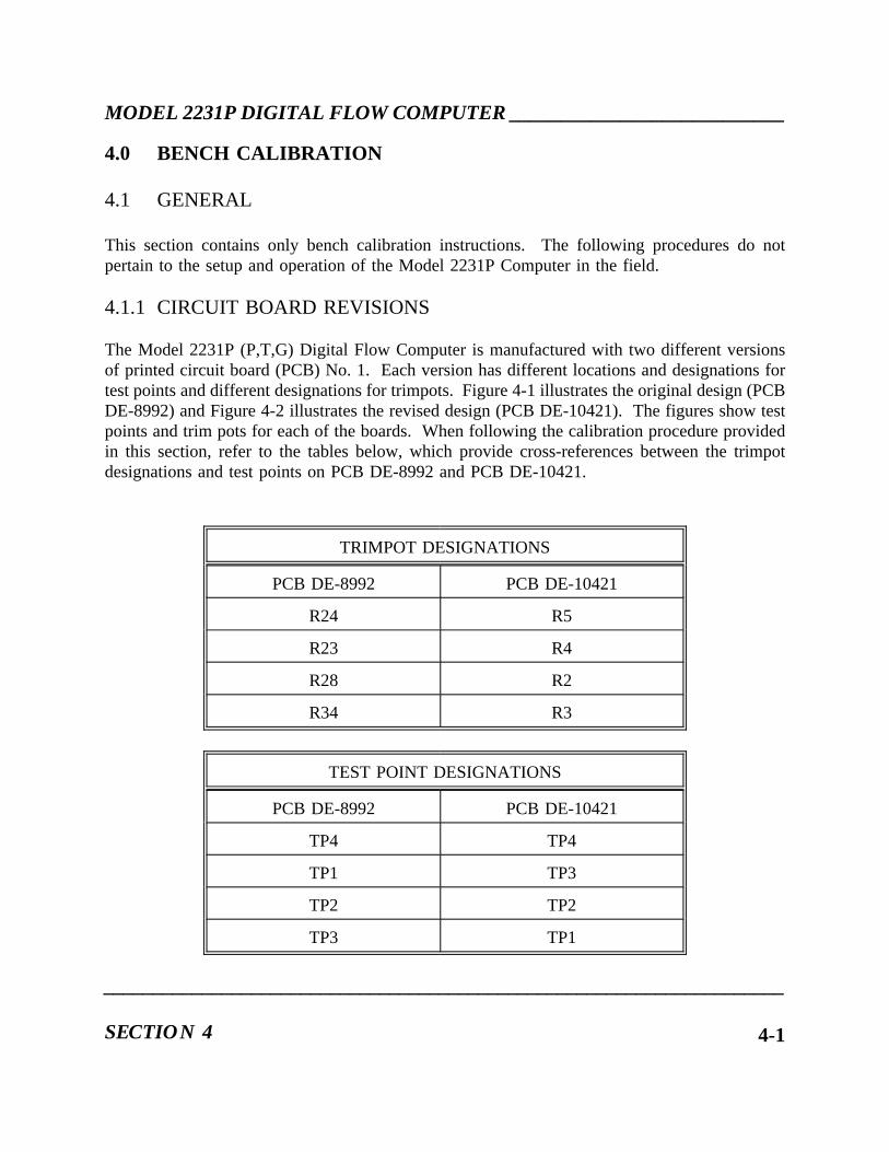
MODEL 2231P DIGITAL FLOW COMPUTER ___________________________
4.0 BENCH CALIBRATION
4.1 GENERAL
This section contains only bench calibration instructions. The following procedures do notpertain to the setup and operation of the Model 2231P Computer in the field.
4.1.1 CIRCUIT BOARD REVISIONS
The Model 2231P (P,T,G) Digital Flow Computer is manufactured with two different versionsof printed circuit board (PCB) No. 1. Each version has different locations and designations fortest points and different designations for trimpots. Figure 4-1 illustrates the original design (PCBDE-8992) and Figure 4-2 illustrates the revised design (PCB DE-10421). The figures show testpoints and trim pots for each of the boards. When following the calibration procedure providedin this section, refer to the tables below, which provide cross-references between the trimpotdesignations and test points on PCB DE-8992 and PCB DE-10421.
TRIMPOT DESIGNATIONS
PCB DE-8992 PCB DE-10421
R24 R5
R23 R4
R28 R2
R34 R3
TEST POINT DESIGNATIONS
PCB DE-8992 PCB DE-10421
TP4 TP4
TP1 TP3
TP2 TP2
TP3 TP1
_____________________________________________________________________
SECTION 4 4-1

___________________________MODEL 2231P DIGITAL FLOW COMPUTER
Figure 4-1. Original PC Board No. 1 Design (DE-8992)
Figure 4-2. Revised PB Board No. 1 Design (DE-10421)
___________________________________________________________________
CALIBRATION PROCEDURES4-2

MODEL 2231P DIGITAL FLOW COMPUTER ___________________________
4.2 BENCH CALIBRATION PROCEDURE
Bench calibration consists of detailed scaling and adjustments which go beyond the levelperformed in the field calibration procedures. Bench calibration procedures are performed at thefactory and are not required on the initial startup on the Model 2230 Series Computer.
4.2.1 DETERMINE THE INSTRUMENT OPTIONS
Compare the dash number located on the computer with the option diagram in Figure 2-1 todetermine the option for which this Model 2231P Computer has been configured.
4.2.2 PROCEDURE
The following bench calibrations are made with a minimum amount of test equipment. Aftercompleting the bench procedure, continue to the field calibration to complete the calibration.
_____________________________________________________________________
SECTION 4 4-3

___________________________MODEL 2231P DIGITAL FLOW COMPUTER
4.2.3 TEST EQUIPMENT
The following test equipment is required to efficiently calibrate the Model 2231P Computer.
Digital Voltmeter, Fluke Model 8800 A or equivalent.
4.2.4 POWER SUPPLY ADJUSTMENTS
A. The input power requirement decal is located on the top of the power supply case, at therear of the instrument. Verify that the proper potential is applied.
B. Check all supply outputs for proper voltages. Only the +24 volts and +5 volts areadjustable. The power supply is a design which uses sense lines for varying loads.Therefore, to insure optimum performance, adjust the +24 volts so that +1.000 volt is readbetween TP1 (positive) and TP3 (negative) on PC Board No.1. Read the +5 voltsbetween pin 24 (positive) and pin 12 (negative) of U3 on PC Board No.1 and adjust toread +5.1 volts ±0.020 volts.
___________________________________________________________________
CALIBRATION PROCEDURES4-4

MODEL 2231P DIGITAL FLOW COMPUTER ___________________________
4.3 FIELD CALIBRATION
4.3.1 RATE VOLTAGE CALIBRATION (Reference Figure 4-3)
A. Enter Read Code 11 to display the Flow Rate Full Scale in SCFH. Make note of thistotal. "Enable" the computer and enter the total into Read Code 18 (full scale volumerate in SCFH).
B. Attach a digital voltmeter to terminals 46 (+) and 49 (-). Adjust span trimpot R23 onP.C. Board No.1 to a reading of +10.000 volts. Enter 0.0 into Read Code 18. Adjustzero trimpot R24 on PC Board No.1 to a reading of 0.0 volts.
Repeat (A) and (B)- until the zero and span are correct without making further adjustments."Disable" the computer.
NOTE: Only one rate voltage output requires calibration. The remaining rate voltageoutputs are calibrated automatically.
4.3.2 RATE CURRENT CALIBRATION (Reference Figure 4-3)
A. Complete the Rate Voltage calibration outlined in Subsection 4.3.1.
B. Enter Read Code 11 to display the Flow Rate Full Scale in SCFH. Make note of thistotal. "Enable" the computer and enter the total into Read Code 18 (full scale volumerate in SCFH).
C. Connect a multimeter to terminals 37 (+) and 57 (-). Adjust gross span trimpot R47 onPC Board No.2 until the meter reads 20.000 mA.
D. Enter 0.0 into Read Code 18 (zero scale volume in SCFH). Adjust zero trimpot R54 onPC Board No.2 until the meter reads 4,000 mA.
E. Repeat (B) and (C) until the zero and span are correct without making furtheradjustments.
F. "Disable" the computer.
_____________________________________________________________________
SECTION 4 4-5

___________________________MODEL 2231P DIGITAL FLOW COMPUTER
4.3.3 REFERENCE VOLTAGE CALIBRATION (Reference Figure 4-3)
A. Set up the +1.000 volt reference and +5.000 volt reference. Attach the positive lead ofa digital voltmeter to TP1 on PC Board No.1 and the negative lead to TP3. Adjust the+24 volts on the power supply until +1.000 volts is indicated. Attach the positive leadto TP2. The voltmeter should read +5.000 volts ±0.04%.
B. Use Command Codes 98 and 99 to adjust the analog zero and span. Press "98 CMD".The alpha-numeric display will display the analog zero value in hex. which should readOE4 to represent +1.000 volts. If it is not OE4, adjust R28 (input zero) on PC BoardNo.1 until OE4 is indicated. Press "99 CMD". The alpha-numeric display will displaythe analog span value in hex, which should read FIC to represent +5.000 volts. If it isnot FIC, adjust R34 (input span) on PC Board No.1 until FIC is indicated. The input zeroand input scan adjustments interact with each other. Therefore, repeat procedures aboveuntil both readings are correct without further adjustments.
This completes the field calibration for the Model 2231P Computer.
NOTE: Reconfigure to original start up configuration before returning the computer toservice per Subsection 2.6.2, Startup Prompting Sequence.
___________________________________________________________________
CALIBRATION PROCEDURES4-6

MODEL 2231P DIGITAL FLOW COMPUTER ___________________________
Figure 4-3. Bench Calibration
_____________________________________________________________________
SECTION 4 4-7

___________________________MODEL 2231P DIGITAL FLOW COMPUTER
This page intentionally left blank.
___________________________________________________________________
CALIBRATION PROCEDURES4-8
MODEL 2231P DIGITAL FLOW COMPUTER ___________________________
5.0 MAINTENANCE
5.1 GENERAL
This section contains information on maintenance, spare parts and procedures for receivingfactory assistance on making repairs.
5.2 PREVENTIVE MAINTENANCE
Preventive Maintenance procedures are not recommended because printed circuit boards can beadversely affected by handling. Therefore, while the Model 2230 Series computer performs tospecifications, maintenance is not required.
5.3 RECOMMENDED SPARE PARTS
Daniel recommends only modular spare parts (e,g, plug-in boards, sub-assemblies, etc.).Recommended spare parts for the Model 2230 Series computer are listed in the Spare Parts listin Section 6. To insure receiving the correct option of each spare part, order the part by its partnumber.
5.4 FACTORY SERVICE FAILURE REPORT
A factory Service Failure Report is located in the back of this section. It is to be used whenreturning the Model 2230 Series computer to the factory for repairs. Completely fill out thisreport and include it with the unit in the shipping container. Be sure to include the dash numberportion of the Model number. This dash number, found on the rear of the unit, and on the backof the title page, describes the exact power requirements and operating characteristics of theinstrument.
5.5 SHIPPING INSTRUCTIONS
Pack the Model 2230 Series computer in its original packing materials (if still available) or ina carton or box with two or three inches of shock absorbing material surrounding it. Shipprepaid via the most suitable method.
___________________________________________________________________
SECTION 5 5-1

___________________________MODEL 2231P DIGITAL FLOW COMPUTER
This page intentionally left blank.
___________________________________________________________________MAINTENANCE5-2

MODEL 2231P DIGITAL FLOW COMPUTER ___________________________
6.0 DRAWINGS AND PARTS LIST
Field Wiring Diagram DE-9413Field Wiring Diagram, Lightning Protection DE-8940Recommended Spare Parts SP-8969-11
____________________________________________________________________
SECTION 6 6-1

___________________________MODEL 2231P DIGITAL FLOW COMPUTER
This page intentionally left blank.
____________________________________________________________________
DRAWINGS6-2


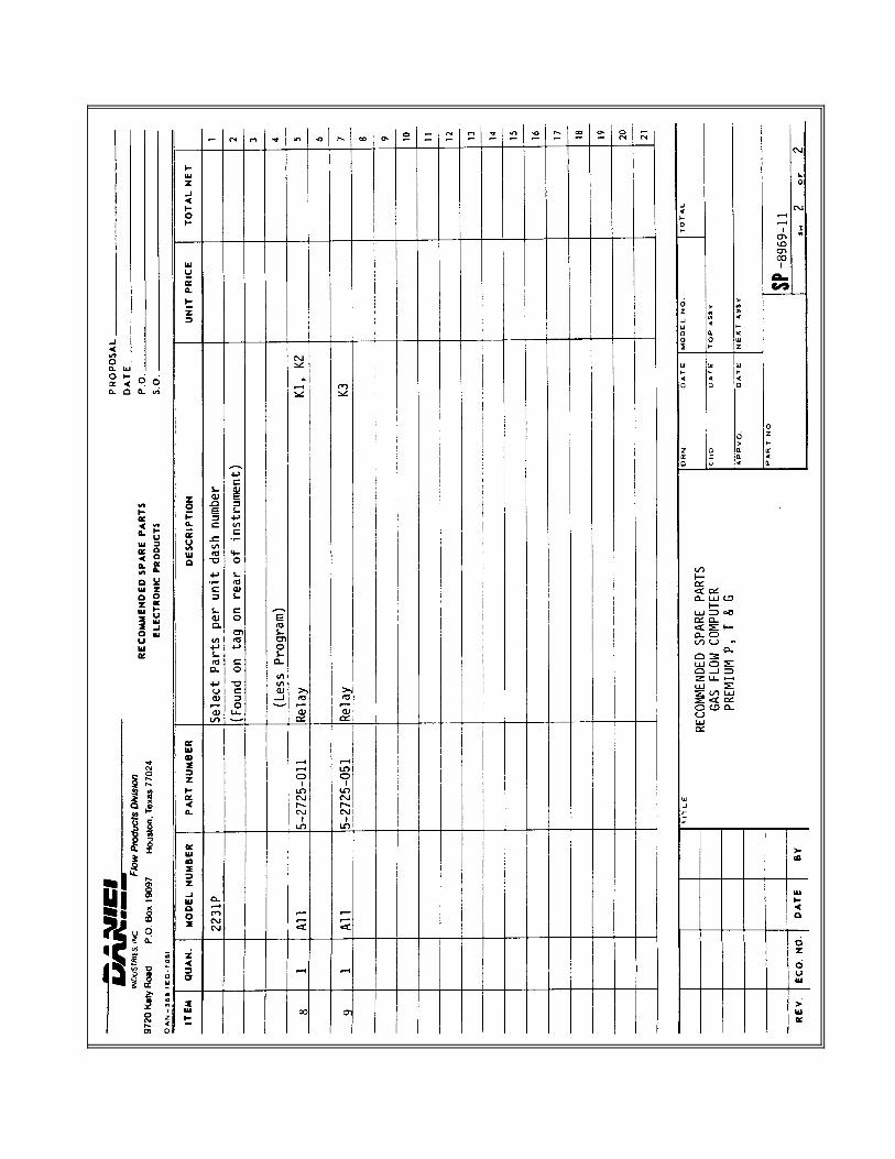


WARRANTY CLAIM REQUIREMENTS
To make a warranty claim, you, the Purchaser, must:
1. Provide Daniel with proof of the Date of Purchase and proof of the Date of Shipment ofthe product in question.
2. Return the product to Daniel within twelve (12) months of the date of original shipmentof the product, or within eighteen (18) months of the date of original shipment of theproduct to destinations outside of the United States. The Purchaser must prepay anyshipping charges. In addition, the Purchaser is responsible for insuring any productshipped for return, and assumes the risk of loss of the product during shipment.
3. To obtain Warranty service or to locate the nearest Daniel office, sales, or service centercall (281) 897-2900, Fax (281) 897-2901, or contact:
Daniel Measurement Services19203 Hempstead HighwayHouston, Texas 77065
When contacting Daniel for product service, the purchaser is asked to provideinformation as indicated on the following "Customer Problem Report".
Daniel Measurement Services offers both on call and contract maintenance servicedesigned to afford single source responsibility for all its products.
Daniel Industries, Inc. reserves the right to make changes at any time to any product toimprove its design and to insure the best available product.


DANIEL INDUSTRIES, INC.CUSTOMER PROBLEM REPORT
FOR FASTEST SERVICE, COMPLETE THIS FORM, AND RETURN IT ALONG WITH THE AFFECTEDEQUIPMENT TO CUSTOMER SERVICE AT THE ADDRESS INDICATED BELOW.
COMPANY NAME:____________________________________________________________________________
TECHNICAL CONTACT:_________________________________ PHONE:______________________________
REPAIR P. O. #:_____________________________ IF WARRANTY, UNIT S/N: _________________________
INVOICE ADDRESS:____________________________________________________________________
_________________________________________________________________
_________________________________________________________________
SHIPPING ADDRESS:___________________________________________________________________
_________________________________________________________________
_________________________________________________________________
RETURN SHIPPING METHOD:__________________________________________________________________
EQUIPMENT MODEL #:____________________ S/N:__________________FAILURE DATE: _____________
DESCRIPTION OF PROBLEM: __________________________________________________________________
______________________________________________________________________________________________
______________________________________________________________________________________________
WHAT WAS HAPPENING AT TIME OF FAILURE? ________________________________________________
______________________________________________________________________________________________
ADDITIONAL COMMENTS: ____________________________________________________________________
______________________________________________________________________________________________
______________________________________________________________________________________________
REPORT PREPARED BY:________________________________ TITLE:________________________________
IF YOU REQUIRE TECHNICAL ASSISTANCE, PLEASE FAX OR WRITE THE MAIN CUSTOMER SERVICEDEPARTMENT AT:
DANIEL MEASUREMENT SERVICES PHONE: (281) 897-2900ATTN: CUSTOMER SERVICE FAX: (281) 897-290119203 HEMPSTEAD HIGHWAYHOUSTON, TEXAS 77065


The sales and service offices of Daniel Industries, Inc. are locatedthroughout the United States and in major countries overseas.
Please contact Daniel Measurement Services at19203 Hempstead Highway, Houston, Texas 77065, or phone (281) 897-2900
for the location of the sales or service office nearest you.Daniel Measurement Services offers both on-call and contract
maintenance service designed to provide single-sourceresponsibility for all Daniel Measurement and Control products.
Daniel Measurement and Control reserves the right to make changes to any of its products or servicesat any time without prior notification in order to improve that product or service and to supply
the best product or service possible.