
Daniel 1500 - Automation Solutions Daniel... · Liquid Turbine Flow Meter Datasheet 1 Overview The...
12
Datasheet January 2013 Daniel ™ 1500 Liquid Turbine Flow Meter
Transcript of Daniel 1500 - Automation Solutions Daniel... · Liquid Turbine Flow Meter Datasheet 1 Overview The...

DatasheetJanuary 2013
Daniel™ 1500Liquid Turbine Flow Meter


DatasheetLiquid Turbine Flow Meter
1www.EmersonProcess.com
OverviewThe Daniel 1500 Liquid Turbine Flow Meter is a volumetric flow metering and transmitting device used extensively in the petroleum industry. It is the meter of choice for accurate measurement of liquid hydrocarbons and other process fluids.
The 1500 Liquid Turbine Meter is specifically designed for pipeline operation and for use within the guidelines of API Chapter 5.3 (Measurement of Liquid Hydrocarbons by Turbine Meters) and the test procedures of API Chapter 4 (Proving Systems).
The meter's proven design of rugged internals provides reliability and up-time availability to ensure continuous 24/7 pipeline operation for demanding crude oil and refined product applications. The 1500 Liquid Turbine Meter features a dual-hanger suspension system, offering upstream and downstream support as well as positive rotor centering. The standard journal bearing is tungsten carbide that delivers exceptional longevity.
The 1500 Liquid Turbine Flow Meter includes a Universal Mounting Box (UMB) housing with up to 2 pickoffs and a dual channel preamplifier. It can be configured with dual UMBs, enabling complete measurement redundancy and offering up to four matched pulse outputs to accommodate a wide variety of metering and proving requirements.
Typical Applications � Crude and refined product pipelines
� Custody transfer and check metering
� Inventory control
� Ship and rail car loading and off-loading
� Crude oil production
� FSO (floating storage and offloading)
� FPSO (floating production, storage and offloading)
Features and Benefits � Output linear with flow rate
� Rangeability of 10 to 1
� Available in 1 to 18-inch line sizes
� High accuracy and repeatability
� Bi-directional flow models available
� High frequency pulse resolution
� Tungsten carbide bearings
� Universal Mounting Box (UMB) housing, dual channel preamplifier and 2 pickoffs
� Single or dual UMB options
� Up to 4 outputs in 2 pairs, each 90° electrically out of phase
� Improved serviceability allows easy access to pickoffs and reduces installation costs
� Simple, easy to maintain, field mountable pickoffs require no interruption of conduit lines while servicing
� Explosion proof / weatherproof housing
� Stainless steel internals
� Rimmed or bladed rotor options
� Stainless steel or carbon steel body construction
� Light product rotor option
Reliability in Tough Applications
Figure 1: Daniel 1500 Turbine Flow Meter

January 2013Daniel 1500
2 www.EmersonProcess.com
Meter Performance Sizes
1" to 2 1/2"
� Linearity: ±0.25%
� Premium Linearity: ±0.15%
� Repeatability: ±0.02%
3" and Larger
� Linearity: ± 0.15%
� Premium Linearity: ±0.1% and ±0.07%
� Repeatability: ± 0.02%
Process ParametersTable 1: Temperature Ratings
Carbon Steel Stainless Steel
Standard -29°C to 82°C
(-20°F to 180°F)-40°C to 82°C(4) (-40°F to 180°F)
High temperature-29°C to 204°C
(-20°F to 400°F) -40°C to 204°C (-40°F to 400°F)
Ambient Temperature 40°C to 60°C (CE)
-40°F to 140°F (UL / C-UL)
Table 2: Pressure Ratings(5)
Size (inch) ANSI Class Carbon Steel Stainless Steel
1 to 18 150 285 psi 275 psi
1 to 18 300 740 psi 720 psi
1 to 18 600 1,480 psi 1,440 psi
1 to 18 900 2,250 psi 2,160 psi
1 to 18 1500 3.705 psi 3,600 psi
Hazardous Area Classifications(3)
� UL / C-UL Class 1, Division 1, Groups C&D
� CE certified Ex d IIB T6 (ATEX)
� NEMA 4 (exceeds IP66)
(1) Please consult Daniel if your requirements are outside the specifications noted below. Other product and material offerings may be available depending on the application.
(2) 3 or 4 pickoff coils require Dual UMB.
(3) The Daniel 1500 Turbine flow meter meets US, Canadian and European industry standards for electrical and intrinsic safety certifications and approvals. Please consult
Daniel for a complete list of agencies and certifications.
(4) Remote mount UMB (option) high temperature > 82°C (180°F), low temperature < -29°C (-20°F).
(5) Max Pressure in PSI @ 38°C (100°F).
Standard Specifications(1)
Electrical PerformancePickoff Specifications
� Type: 2-wire reluctance
� Resistance: 600 - 900 ohms
� Inductance: 250mH max
� Output: Sinusoidal 40mV p-p minimum @minimum flow with preamplifier load
� Optional: 2, 3 or 4 pickoff coils(2)
Preamplifier Performance (Dual Channel)
� Inputs supply voltage: 10 - 30 V dc
� Minimum input signal amplitude: 40mV p-p minimum
Powered Pulse Output
� Output: 0 to 5V square wave
� Frequency range: 0 to 5 kHz
� Loading: 1 kilohm internal pull-up
Variable Voltage Output
� Output: 0 to supply voltage square wave
� Frequency range: 0 to 5 kHz
� Loading: 1 kilohm internal pull-up
Open Collector Output
� Output: Square wave
� Frequency range: 0 to 5 kHz
� Maximum voltage: 30 V dc
� Maximum current: 125 mA
� Maximum power: 0.5 Watts

DatasheetLiquid Turbine Flow Meter
3www.EmersonProcess.com
Standard Flow Ranges
Table 3: Flow Rate
Size
(Inches)
BBL/HR M3/HR USGPM
Standard Flow
Range Ext Max Flow
Range(1)
Standard Flow
RangeExt Max Flow
Range(1)
Ext Min Flow Range USGPM
Linearity0.75% (1”- 2.5”)
0.50% (3”- 18”)
Standard Flow
RangeExt Max Flow
Range(1)
Min Max Min Max Min Max
1 10 100 115 1.6 16 18 5.6 7 70 81
1.5 21 214 246 3.4 34 39 12 15 150 173
2 43 429 493 6.8 68 78 24 30 300 345
2.5 57 571 657 9.1 91 105 32 40 400 460
3 100 1,000 1,150 15.9 159 183 56 70 700 805
4 185 1,850 2,128 29.4 294 338 104 130 1,295 1,489
6 420 4,200 4,830 66.8 668 768 235 294 2,940 3,381
8 850 8,500 9,775 135 1,351 1,554 476 595 5,950 6,843
10 1,200 12,000 13,800 191 1,908 2,194 672 840 8,400 9,660
12 1,800 18,000 20,700 286 2,862 3,291 1,008 1,260 12,600 14,490
16 2,800 28,000 32,200 445 4,452 5,120 1,568 1,960 19,600 22,540
18 4,000 40,000 46,000 636 6,359 7,313 2,240 2,800 28,000 32,200
Table 4: Linearity
Size (Inches) Standard Linearity Premium Linearity
1- 2.5 +/-0.25% +/-0.15%
3- 18 +/-0.15%+/-0.1%
+/-0.07%*
* 5:1 Turndown
Table 5: Nominal K-Factor
Size (Inches) Pulses/BBL Pulses/M3 Pulses/US Gal
Blade Rim Blade Rim Blade Rim
1 21,000 N/A 132,086 N/A 500 N/A
1.5 9,660 N/A 60,760 N/A 230 N/A
2 5,334 N/A 33,550 N/A 127 N/A
2.5 3,150 N/A 19,813 N/A 75.0 N/A
3 2,016 4,620 12,680 29,059 48.0 110
4 1,000 2,999 6,287 18,862 23.8 71.4
6 235 1,000 1,479 6,287 5.6 23.8
8 N/A 500 N/A 3,144 N/A 11.9
10 N/A 252 N/A 1,585 N/A 6.0
12 N/A 202 N/A 1,268 N/A 4.8
16 N/A 101 N/A 634 N/A 2.4
18 N/A 101 N/A 634 N/A 2.4
(1) Extended Flow Range with 20% Duty Cycle not to Exceed 2 Hours per Day.

January 2013Daniel 1500
4 www.EmersonProcess.com
Flow Range AdjustmentsHigh Viscosity Liquids
Increases in viscosity of the measured liquid will reduce the rangeability of the flow meter. Generally, the minimum flow rate of the meter will have to be increased to maintain the linearity rating of the meter.
The increased flow rate may be determined according to the following ratio:
Sizing ratio = Liquid Viscosity (Centistokes)
Nominal Line Sizes
Table 7: Minimum FlowSizing
Ratio (Inches)
Minimum Flow
(% of Normal Maximum Flow Rate)
1 Use Normal Minimum Flow Rate
1.5 20%
2 25%
2.5 30%
3 35%
4 40%
5 45%
6 50%
7 55%
8 60%
Example:
The sizing ratio of a 4-inch turbine meter measuring a liquid of 8 cSt is 8/4, or 2. The normal maximum flow rate of this size of meter is 1295 GPM. The new minimum flow rate is 25% of 1295, or 324 GPM. The flow rate for this application is now 324-1295 GPM, with standard linearity (+/-0.15%) and repeatability of (+/-0.02%) maintained.
Note: Use of the turbine meter on high viscosity liquids at the maximum extended flow range is allowable, but may increase the wear rate of the turbine.
The pressure drop through the meter may be estimated (for low to medium viscosities) according to the following formula:
DP = (PD) x (μ)1/4 x (SG)3/4 or DP = (PD) x (v)1/4 x (SG)
Where:
DP = Estimated pressure drop PD = Pressure drop for water at expected flow rate μ = Absolute viscosity in centipoises v = Kinematic viscosity in centistokes SG = Specific gravity
Note: μ = (v) x (SG)
Specific Gravity Table 6A: Specific Gravity = 1 (0.7 to 1)
Meter
Size
(Inches)
Minimum Linear
Flow Rate
Maximum Linear
Flow RateBBL/HR M3/HR USGPM BBL/HR M3/HR USGPM
1 10 1.6 7 100 15.9 70 1.5 21 3.4 15 214 34.1 150 2 43 6.8 30 429 68.1 300
2.5 57 9.1 40 571 90.9 400 3 100 15.9 70 1,000 159 700 4 186 29.5 130 1,850 294 1,295 6 420 66.8 294 4,200 668 2,940
Table 6B: Specific Gravity = 0.6Meter
Size
(Inches)
Minimum Linear
Flow Rate
Maximum Linear
Flow RateBBL/HR M3/HR USGPM BBL/HR M3/HR USGPM
1 17 2.7 12 116 18.4 81 1.5 36 5.7 25 247 39.3 173 2 71 11.4 50 493 78.4 345
2.5 96 15.2 67 657 105 460 3 167 26.6 117 1,150 183 805 4 309 49.1 216 2,127 338 1,489 6 701 112 491 4,830 768 3,381
Table 6C: Specific Gravity = 0.5Meter
Size
(Inches)
Minimum Linear
Flow Rate
Maximum Linear
Flow RateBBL/HR M3/HR USGPM BBL/HR M3/HR USGPM
1 23 3.6 16 116 18.4 81 1.5 50 7.9 35 247 39.3 173 2 101 16.1 71 493 78.4 345
2.5 134 21.3 94 657 105 460 3 236 37.5 165 1,150 183 805 4 436 69.3 305 2,127 338 1,489 6 989 157 692 4,830 768 3,381
Table 6D: Specific Gravity = 0.4Meter
Size
(Inches)
Minimum Linear
Flow Rate
Maximum Linear
Flow RateBBL/HR M3/HR USGPM BBL/HR M3/HR USGPM
1 29 4.5 20 116 18.4 81 1.5 60 9.5 42 247 39.3 173 2 120 19.1 84 493 78.4 345
2.5 160 25.4 112 657 105 460 3 280 44.5 196 1,150 183 805 4 517 82.2 362 2,127 338 1,489 6 1,173 187 821 4,830 768 3,381
Table 6E: Specific Gravity = 0.3Meter
Size
(Inches)
Minimum Linear
Flow Rate
Maximum Linear
Flow RateBBL/HR M3/HR USGPM BBL/HR M3/HR USGPM
1 33 5.2 23 116 18.4 81 1.5 71 11.4 50 247 39.3 173 2 141 22.5 99 493 78.4 345
2.5 190 30.2 133 657 105 460 3 331 52.7 232 1,150 183 805 4 613 97.4 429 2,127 338 1,489 6 1,393 221 975 4,830 768 3,381

DatasheetLiquid Turbine Flow Meter
5www.EmersonProcess.com
Flow Conditioning Plate(Optional 3"-6" only)
Deflector RingThrust Washer
Hanger Hub
Hanger Blades
Upstream Cone
Pickoff A
Pickoff B
Rotor Assembly
Downstream Cone
Hanger Hub
Hanger Blades
Shaft
UMB
Thrust Washer
Product Diagrams
Table 8: Preamp Jumper Configurations
Jumper A B Out
J1-Chan. A Input NA 40mV. PP Min NA
J2-Chan. B Input NA 40mV. PP Min NA
J3-Chan. A Output 5v.Pulse Sup. Volt. Pulse (10-30 VDC) O.C.
J4-Chan. B Output 5v.Pulse Sup. Volt. Pulse (10-30 VDC) O.C.
Electrical
Meter Assembly
Figure 2: Dual Channel Preamp Terminal Identification Customer Connections
DUAL CHANNEL PREAMPTERMINAL IDENTIFICATIONCUSTOMER CONNECTIONS
Black or Red
PickoffPickoff
White
White
Channel BChannel A
Black or Red
TB1 1 2 3 4 5
2
1 2 1TB2 TB3
JUMPER POSITIONS JUMPER A B OUT J1-CHAN. A INPUT N/A 40mV. PP MIN N/A J1-CHAN. B INPUT N/A 40mV. PP MIN N/A J3-CHAN. A OUTPUT 5V.PULSE SUP. VOLT. PULSE (10-30 VDC) O.C. J4-CHAN. B OUTPUT 5V.PULSE SUP. VOLT. PULSE (10-30 VDC) O.C.
PREAMP JUMPER CONFIGURATIONS
J3 J4
J2J1
Channel B OutputCom
mon
Channel A OutputCom
mon
+10 To 30 VDC

January 2013Daniel 1500
6 www.EmersonProcess.com
Materials of Construction
Table 9A: Meter with Bladed Rotor (1" to 6")Meter Body and Flanges Carbon Steel Stainless Steel (304SS) Stainless Steel (316SS)Universal Mounting Box (UMB) Aluminum 356-T6 Aluminum 356-T6 Aluminum 356-T6Blades
1" 430SS / 304SS 430SS / 304SS NICKEL-200 / 316SS(1)
1.5" to 6" 430SS 430SS NICKEL-200(2)
Rotor Hub 1" to 6" 430SS 430SS 316SS
Shaft1" to 2.5" 316SS 316SS 316SS3" to 6" 17-4 PH SS HT(3) 17-4 PH SS HT(3) 17-4 PH SS HT(3)
Tolerance Rings (2.5"-24") K-MONEL K-MONEL K-MONELBearing Set Tungsten Carbide Tungsten Carbide Tungsten CarbideSuspension 304SS 304SS 316SSCones 304SS 304SS 316SS
Table 9B: Meter with Rimmed Rotor (3" to 24")Meter Body and Flanges Carbon Steel Stainless Steel (304SS) Stainless Steel (316SS)Universal Mounting Box (UMB) Aluminum 356-T6 Aluminum 356-T6 Aluminum 356-T6Blades 304SS 304SS 316SSRotor Hub 430SS 430SS 316SSRotor Rim
3" and 4" 316SS 316SS 316SS6" and 24" 304SS 304SS 316SS
Shaft 17-4 PH SS HT(3) 17-4 PH SS HT(3) 17-4 PH SS HT(3)
Tolerance Rings K-MONEL K-MONEL K-MONELBearing Set Tungsten Carbide Tungsten Carbide Tungsten CarbideSuspension 304SS 304SS 316SSDeflector Ring 304SS 304SS 316SSRim Buttons Mu-Metal Mu-Metal Mu-MetalCones 304SS 304SS 316SS
Table 9C: Meter with Light Weight Rotor (3" to 12")Meter Body and Flanges Carbon Steel Stainless Steel (304SS) Stainless Steel (316SS)Universal Mounting Box (UMB) Aluminum 356-T6 Aluminum 356-T6 Aluminum 356-T6Blades
3" to 4" (Blade Type) 430SS 430SS 430SS6" to 12" (Rim Type) 304SS 304SS 304SS
Rotor Hub3" 430SS 430SS 430SS4" to 12" 6061-T6 ALUM 6061-T6 ALUM 6061-T6 ALUM
Shroud (6"-12") 430SS 430SS 430SSShaft 17-4 PH SS HT(3) 17-4 PH SS HT(3) 17-4 PH SS HT(3)
Tolerance Rings K-MONEL K-MONEL K-MONELBearing Set Tungsten Carbide Tungsten Carbide Tungsten CarbideSuspension 304SS 304SS 304SSDeflector Ring 304SS 304SS 316SSCones 304SS 304SS 304SS
Standard Materials
NOTE: Teflon Coated rotor available for Rim and Blade type.
(1) For full NACE MR0175:2002 compliancy, material will change to 430SS.
(2) Rim type rotor not recommended, use blade type rotor only.
(3) For full NACE MR0175:2002 compliancy, material will change to 316SS with hard chrome or optional full NACE MR175/ISO151: 2003.
DatasheetLiquid Turbine Flow Meter
7www.EmersonProcess.com
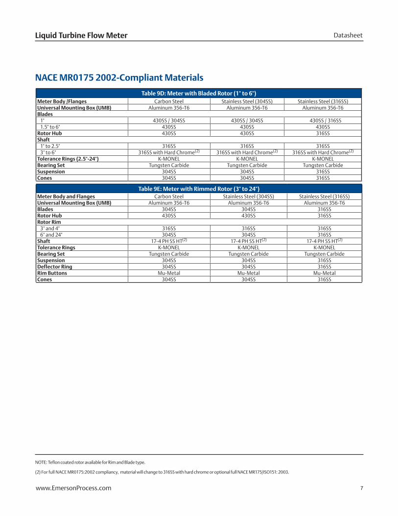
Table 9D: Meter with Bladed Rotor (1" to 6")Meter Body /Flanges Carbon Steel Stainless Steel (304SS) Stainless Steel (316SS)Universal Mounting Box (UMB) Aluminum 356-T6 Aluminum 356-T6 Aluminum 356-T6Blades
1" 430SS / 304SS 430SS / 304SS 430SS / 316SS1.5" to 6" 430SS 430SS 430SS
Rotor Hub 430SS 430SS 316SSShaft
1" to 2.5" 316SS 316SS 316SS3" to 6" 316SS with Hard Chrome(2) 316SS with Hard Chrome(2) 316SS with Hard Chrome(2)
Tolerance Rings (2.5"-24") K-MONEL K-MONEL K-MONELBearing Set Tungsten Carbide Tungsten Carbide Tungsten CarbideSuspension 304SS 304SS 316SSCones 304SS 304SS 316SS
Table 9E: Meter with Rimmed Rotor (3" to 24")Meter Body and Flanges Carbon Steel Stainless Steel (304SS) Stainless Steel (316SS)Universal Mounting Box (UMB) Aluminum 356-T6 Aluminum 356-T6 Aluminum 356-T6Blades 304SS 304SS 316SSRotor Hub 430SS 430SS 316SSRotor Rim
3" and 4" 316SS 316SS 316SS6" and 24" 304SS 304SS 316SS
Shaft 17-4 PH SS HT(2) 17-4 PH SS HT(2) 17-4 PH SS HT(2)
Tolerance Rings K-MONEL K-MONEL K-MONELBearing Set Tungsten Carbide Tungsten Carbide Tungsten CarbideSuspension 304SS 304SS 316SSDeflector Ring 304SS 304SS 316SSRim Buttons Mu-Metal Mu-Metal Mu-MetalCones 304SS 304SS 316SS
NACE MR0175 2002-Compliant Materials
NOTE: Teflon coated rotor available for Rim and Blade type.
(2) For full NACE MR0175:2002 compliancy, material will change to 316SS with hard chrome or optional full NACE MR175/ISO151: 2003.

January 2013Daniel 1500
8 www.EmersonProcess.com
Table 10: Daniel 1500 Liquid Turbine Flow Meter and Flow Straightening Sections
Sizes (Inches)A B C D E F
INCHES MM INCHES MM INCHES MM INCHES MM INCHES MM INCHES MM
1 8 203 4 102 6.75 171 N/A N/A N/A N/A N/A N/A
1.5 9 229 4.5 114 7.13 181 N/A N/A N/A N/A N/A N/A
2 9 229 4.5 114 7.13 181 21 533 13 330 43 1,092
2.5 10 254 5 127 7.56 192 25 635 15 381 50 1,270
3 10 254 5 127 7.50 191 30 762 15 381 55 1,397
4 12 305 6 152 8.25 210 40 1,016 20 508 72 1,829
6 14 356 7 178 9.31 237 60 1,524 30 762 104 2,642
8 16 406 8 203 10.31 262 80 2,032 40 1,016 136 3,454
10 20 508 10 254 11.38 289 100 2,540 50 1,270 170 4,318
12 24 610 12 305 12.38 314 120 3,048 60 1,524 204 5,182
16 32 813 16 406 14 356 160 4,064 80 2,032 272 6,909
18 36 914 18 457 15 381 180 4,572 90 2,286 306 7,772N/A = Not Applicable
Table 11: Approximate Shipping Weight
Sizes (Inches)ANSI Class 150 ANSI Class 300 ANSI Class 600 ANSI Class 900 ANSI Class 1500
lbs kg lbs kg lbs kg lbs kg lbs kg
1 11 5.0 13 5.9 15 6.8 29 13.1 29 13.1
1.5 18 8.1 21 9.5 24 10.9 45 20.4 45 20.4
2 20 9.1 22 10.0 26 11.8 66 29.9 66 29.9
2.5 29 13.1 35 15.8 40 18.1 88 39.8 88 39.8
3 32 14.5 42 19.0 46 20.8 88 39.8 133 60.2
4 46 20.8 68 30.8 87 39.4 135 61.1 200 90.5
6 77 34.8 112 50.7 169 76.5 265 120 375 170
8 121 54.8 180 81.5 275 125 426 193 570 258
10 207 93.7 280 127 460 208 658 298 1,020 462
12 321 145 433 196 590 267 896 406 1,560 706
16 730 330 836 378 1,260 570 CF CF CF CF
18 1,093 495 1,160 525 1,660 751 CF CF CF CFCF = Consult Factory
For ANSI ratings not listed, please consult factory.
B
C
F
EAD
4 - 1/2”(114 mm)
UPSTREAM FLOWSTRAIGHTENER
(OPTIONAL)
DOWNSTREAM FLOWSTRAIGHTENER
(OPTIONAL)
Minimum distance requirements for service
3”(76.2 mm)
For certified dimension prints, please consult factory
A B C D E F(Inches) Inches mm Inches mm Inches mm Inches mm Inches mm Inches mm
1 8 203 4 102 6 3/4 171 N/A N/A N/A N/A N/A N/A1.5 9 229 4.5 114 7 1/8 181 N/A N/A N/A N/A N/A N/A2 9 229 4.5 114 7 1/8 181 21 533 13 330 43 1,092
2.5 10 254 5 127 7 9/16 192 25 533 15 330 46 1,1683 10 254 5 127 7 1/2 197 30 762 15 381 55 1,3974 12 305 6 152 8 1/4 209 40 1,016 20 508 72 1,8296 14 356 7 178 9 5/16 236 60 1,524 30 762 104 2,6428 16 406 8 203 10 5/16 262 80 2,032 40 1,016 136 3,45410 20 508 10 254 11 3/8 289 100 2,540 50 1,270 170 4,31812 24 610 12 305 12 3/8 314 120 3,048 60 1,524 204 5,18216 32 813 16 406 14 356 160 4,064 80 2,032 272 6,90918 36 914 18 457 15 381 180 4,572 90 2,286 306 7,772
Sizes
(5D)(10D)
Weights and Dimensions

DatasheetLiquid Turbine Flow Meter
9www.EmersonProcess.com
T XX X X X X
Device
Series 1500 T
Line Size / Standard Flow Range
1" DN25 (7-70 GPM, 10-100 BHP, 1.6-16 M³/H) 01
1.5" DN40 (15-150 GPM, 21-214 BHP, 3.4-34 M³/H) 15
2" DN50 (30-300 GPM, 43-429 BHP, 6.8-68 M³/H) 02
2.5" DN65 (40-400GPM, 57-571 BHP, 9.1-91M³/H) 25
3" DN80 (70-700 GPM, 100-1000 BHP, 15.9-159 M³/H) 03
4" DN100 (130-1295 GPM, 185-1850 BHP, 29.4-294 M³/H) 04
6" DN150 (294-2940 GPM, 420-4200 BHP, 66.8-668 M³/H) 06
8" DN200 (595-5950 GPM, 850-8500 BHP, 135-1351 M³/H) 08
10" DN250 (840-8400 GPM, 1200-12000 BHP, 191-1908 M³/H) 10
12" DN300 (1260-12600 GPM, 1800-18000 BHP, 286-2862 M³/H) 12
16" DN400 (1960-19600 GPM, 2800-28000 BHP, 445-4452 M³/H) 16
18" DN450 (2800-28000 GPM, 4000-40000 BHP, 636-6359 M³/H) 18
Pressure Rating / Flange Type
150# ANSI, RF (Sizes 1" - 18", 285 psi MWP, 125-250 AARH) A
300# ANSI, RF (Sizes 1" - 18", 740 psi MWP, 125-250 AARH) B
600# ANSI, RF (Sizes 1" - 18", 1480 psi MWP, 125-250 AARH) C
900# DANIEL, RTJ (Sizes 1" - 4", 2220 psi MWP) G
1500# DANIEL, RTJ (Sizes 1" - 2.5", 3705 psi MWP) H
2500# DANIEL, RTJ (Sizes 1" - 2.5", 6170 psi MWP) J
Design Style / Enclosure Style
1 Aluminum UMB (Sizes 1" - 18") D
2 Aluminum UMBs (Sizes 3" - 18") Z
Meter Output / Temperature Range
Standard Temperature Options (-29°C to 82°C)
1 Pick-Off, 1 Dual Channel Preamp A
2 Pick-Offs (90° Out of Phase), 2 Dual Channel Preamps B
2 Pick-Offs (90° Out of Phase), 1 Dual Channel Preamp C
1 Pick-Off Only D
2 Pick-Offs Only (90° Out of Phase) E
4 Pick-Offs (Each Pair 90° Out of Phase), 2 Dual Channel Preamps L
High Temperature Options (-29°C to 204°C)
1 Pick-Off, 1 Dual Channel Preamp F
2 Pick-Offs (90° Out of Phase), 2 Dual Channel Preamps G
2 Pick-Offs (90° Out of Phase), 1 Dual Channel Preamp H
1 Pick-Off Only J
2 Pick-Offs (90° Out of Phase), 1 Terminal Block K
2 Pick-Offs (90° Out of Phase), 2 Terminal Blocks, RMB with Dual Channel Preamp M
1 Pick-Off, 1 Terminal Block, RMB with Dual Channel Preamp N
Metrology Approvals
Unspecified 1
OIML (Sizes 3" - 16") 5
Daniel 1500 Turbine Flow Meter Selection Matrix
This is for informational purposes only. Not every option is listed and some options are contingent on others. Please consult factory for assistance designing your optimal meter.
X X X X X X X X
Other Documentation
A None
C Material Test Reports (DOC MTR)
E NACE with Material Test Report - Compliant with MR0175 2002; Special Order for NACE
MR0175 /ISO 151 2003
Approvals / Documentation
J UL / CUL
K CE (Includes ATEX, PED or SEP and EMC )
M INMETRO
Linearity
C 1" - 2.5" (+/- 0.25%), 3" - 18" (+/- 0.15%)
D 1" - 2.5" (+/- 0.15%), 3" - 18" (+/- 0.10%)
E 3" - 18" (+/- 0.07% with 5:1 Turndown)
Display Mounting
A None
B Integral
C Remote
Display
A None
D MRT-97 Electronic Register
Materials of Construction
Body / Flange / Internals
1 304 SS / 304 SS / 304 SS
2 CS / CS / 304 SS
4 316 SS / 316 SS / 316 SS
5 CS / CS / 316 SS
Flow Direction / Flow Conditioning
A Horizontal, No Flow Conditioning Plate
B Vertical, No Flow Conditioning Plate
C Horizontal, Flow Conditioning Plate (Aluminum, Sizes 3" - 8" Only)
D Vertical, Flow Conditioning Plate (Aluminum, Sizes 3" - 8" Only)
E Horizontal, Bi-Directional, No Flow Conditioning Plate
Rotor Type
A Blade-Type Rotor, Uni-Directional, Sizes 1" - 6"
F Teflon Coated Blade-Type Rotor, Uni-Directional, Sizes 1" - 6"
B Blade-Type Rotor, Bi-Directional, Sizes 1" - 6"
G Teflon Coated Blade-Type Rotor, Bi-Directional, Sizes 1" - 6"
C Rim-Type Rotor, Uni-Directional, Sizes 3" - 18"
H Teflon Coated Rim-Type Rotor, Uni-Directional, Sizes 3" - 16"
D Rim-Type Rotor, Bii-Directional, Sizes 3" - 18"
J Teflon Coated Rim-Type Rotor, Bi-Directional, Sizes 3" - 16"
M Light Product Rotor, Uni-Directional, Sizes 3" - 12"

©2013 Daniel Measurement and Control, Inc. All Rights Reserved. Unauthorized duplication in whole or in part is prohibited. Printed in the USA. DAN-LIQ-DS-1500TM-0113
Daniel Measurement and Control, Inc. (“Daniel”) is an Emerson Process Management business unit. The Daniel name and logo are trademarks of Daniel Industries, Inc. The Emerson logo is a trademark and service mark of Emerson Electric Co. All other trademarks are the property of their respective companies.
Emerson Process Management
Daniel Measurement and Control, Inc. North America / Latin America: Headquarters USA - Houston, Texas T +1.713.467.6000 USA Toll Free 1.888.FLOW.001
www.Daniel.com
Europe: Stirling, Scotland, UK T +44.1786.433400 Middle East, Africa: Dubai, UAE T +971.4.811.8100 Asia Pacific: Singapore T +65.6777.8211
Scan with your smart phone for more information