Modal Analysis of Goodrich Landing Gear for the · PDF file6 SOUND & VIBRATION/NOVEMBER 2008...
2
www.SandV.com 6 SOUND & VIBRATION/NOVEMBER 2008 Modal Analysis of Goodrich Landing Gear for the A380 S&V OBSERVER LMS Engineering Services performed a modal test campaign on Goodrich landing gear for the Airbus A380. In the “Super Rig” at Goodrich Corporation’s landing-gear facility in Oakville, Ontario, Canada, LMS engineering consultants subjected a body landing gear prototype assembly for the Air- bus A380 to experimental modal analysis (EMA). After suspending the 12,000-pound body gear 12 feet high above the floor, they applied burst-random and stepped-sine excitation at up to 1,000 Newton force lev- els. The major landing gear mode shapes extracted from the test data, both in static and fully extended stroke, supported struc- tural studies at Airbus and helped engineers verify finite-element (FE) models generated by Goodrich’s Landing Gear Division. Largest Landing Systems Supplier. Goodrich landing gear has a distinguished history that dates back to 1926, when Cleve- land Pneumatic Tool Company, now part of Goodrich, introduced the industry’s first air- oil landing gear strut. Goodrich merged with Menasco in 1999 to become the world’s larg- est supplier of landing gear systems. Today, Goodrich delivers landing gear systems to major aircraft companies, including Agusta, Airbus, Boeing, Bombardier, Gulfstream and Lockheed Martin. The success of Goodrich’s Landing Gear Division is measured with each takeoff and landing that is executed with its equipment. Since the Airbus A380 weighs approximately 1,300,000 pounds when fully loaded, this double-deck jetliner sets rigorous requirements on landing gear design and development. To assure safe and comfortable takeoff, landing and taxiing of this super-size aircraft, Airbus selected Goodrich for developing and producing the A380 landing gear systems. Building on LMS’s Modal Test Skills. To support a structural testing campaign to be performed on the starboard body landing gear system, Goodrich contracted with the U.S.-based team of LMS Engineering Ser- vices. “The LMS assignment involved EMA on a landing gear system, which allowed them to validate FE models of this rather complex mechanical assembly,” said Alvin Fong, manager of landing gear performance at Goodrich’s Oakville landing gear facility. “The six-wheel landing gear system weighs approximately 12,000 pounds, and its size exceeds 25 feet when fully extended. In landing gear system development, it is our task to meet the required stability and structural performance to ensure that the gear will safely react to all loads and cir- cumstances it will encounter throughout its service life.” The structural test campaign for the A380 landing gear was performed at the Goodrich landing gear test facility in Oakville. The central feature of this facility is the “Super Rig,” an extremely large steel structure that encompasses nine test bays, each capable of handling an A380 body or wing gear. The entire Super Rig structure sits in a three- foot-deep pit approximately the size of two football fields. The body landing gear prototype to be subjected to the modal test campaign filled Bay No. 2 to the limit. The steel rig structure allowed the large-body landing gear to be suspended in free-free conditions. The test set-up also required LMS to fabricate two solid stands, each filled with 5,000 pounds of concrete. To avoid freeplay in landing gear joints as much as possible, LMS consultants pre- loaded the body landing gear unit with static forces that were applied vertically through bungee cords. The measurement instrumentation consisted of SCADAS 316 data acquisition systems as well as LMS Test.Lab software, including the LMS PolyMAX modal parameter estimator. The instrumentation also controlled the modal excitation systems. Validating Modal Test Set-Up. To be able to provide sufficient energy while performing modal tests on a specimen of this size and weight, LMS engineering consultants installed multiple shakers. Two electro-dynamic shakers – each capable of generating 1,000 Newtons – were used to provide either burst-random or stepped- sine excitation. Initial modal tests showed that the test rig itself exhibited fundamental fore-aft motion around 5 and 8 Hz. As these dominant frequencies fell proximate to the 0-10 Hz frequency of interest for landing gear modal testing, significant dynamic coupling between gear modes and test rig modes were observed. To monitor this inter- ference throughout the test campaign, LMS engineers added a number of measurement points to the modal test geometry of the landing gear assembly. To verify the quality of the modal test set-up, LMS consultants evaluated auto- power spectra as well as frequency response functions (FRFs), coherence and reciprocity. These checks indicated whether all input energy is present at the output side and whether excitation and measurement points are located favorably. Auto-power spectra related to front and rear shaker excitation showed that both shaker inputs were of the same force level and excited all frequen- cies equally across the frequency range of interest. “When evaluating structural FRF coherence and reciprocity, the two-burst random shaker inputs created only limited nonlinear landing gear behavior in static stroke and extended positions at specified force levels between 5 and 15 Newtons,” Paul Weal, business development manager of LMS Engineering Services, explained. “However, when increasing force levels using stepped-sine excitation – 200 to 1,000 Newtons – we identified stronger nonlinear behavior, mainly as a result of slight back- lash that was present in the huge landing gear joint connections. When testing at highest force levels, the resulting bending and torsion modes became truly visible, as we witnessed displacements of about 1 inch. With the help of driving point FRF functions, we quantified the evolution of growing nonlinearity that is exhibited in response to increasing force levels.” Selecting Landing Gear Modes. The ac- tual modal analysis test campaign started with the selection of the landing gear modes. LMS consultants quickly obtained insight into modal resonance through the sum-blocks function of LMS Test.Lab, which emphasizes modal resonance by dis- playing a summation of all measured FRFs. Based on the acquired data, the individual modal parameters were extracted using the innovative LMS PolyMAX curve fitter. The modal parameters then served as a basis to synthesize FRFs through calculation. The high level of correlation between measured and synthesized FRFs showed that the modal analysis was successful in accurately reproducing the measured FRFs. Fong said, “The most significant modes retrieved for the landing gear static stroke The six-wheel landing gear system weighs ap- proximately 12,000 pounds and is more than 25 feet long when fully extended. The major mode shapes extracted from the test data were used to verify finite-element landing gear models at Goodrich and supported structural investigations at Airbus.
Transcript of Modal Analysis of Goodrich Landing Gear for the · PDF file6 SOUND & VIBRATION/NOVEMBER 2008...
www.SandV.com6 SOUND & VIBRATION/NOVEMBER 2008
Modal Analysis of Goodrich Landing Gear for the A380
S&V OBSERVER
LMS Engineering Services performed a modal test campaign on Goodrich landing gear for the Airbus A380. In the “Super Rig” at Goodrich Corporation’s landing-gear facility in Oakville, Ontario, Canada, LMS engineering consultants subjected a body landing gear prototype assembly for the Air-bus A380 to experimental modal analysis (EMA). After suspending the 12,000-pound body gear 12 feet high above the floor, they applied burst-random and stepped-sine excitation at up to 1,000 Newton force lev-els. The major landing gear mode shapes extracted from the test data, both in static and fully extended stroke, supported struc-tural studies at Airbus and helped engineers verify finite-element (FE) models generated by Goodrich’s Landing Gear Division.
Largest Landing Systems Supplier. Goodrich landing gear has a distinguished history that dates back to 1926, when Cleve-land Pneumatic Tool Company, now part of Goodrich, introduced the industry’s first air-oil landing gear strut. Goodrich merged with Menasco in 1999 to become the world’s larg-est supplier of landing gear systems. Today, Goodrich delivers landing gear systems to major aircraft companies, including Agusta, Airbus, Boeing, Bombardier, Gulfstream and Lockheed Martin. The success of Goodrich’s Landing Gear Division is measured with each takeoff and landing that is executed with its equipment. Since the Airbus A380 weighs approximately 1,300,000 pounds when fully loaded, this double-deck jetliner sets rigorous requirements on landing gear design and development. To assure safe and comfortable takeoff, landing and taxiing of this super-size aircraft, Airbus selected Goodrich for developing and producing the
A380 landing gear systems.Building on LMS’s Modal Test Skills. To
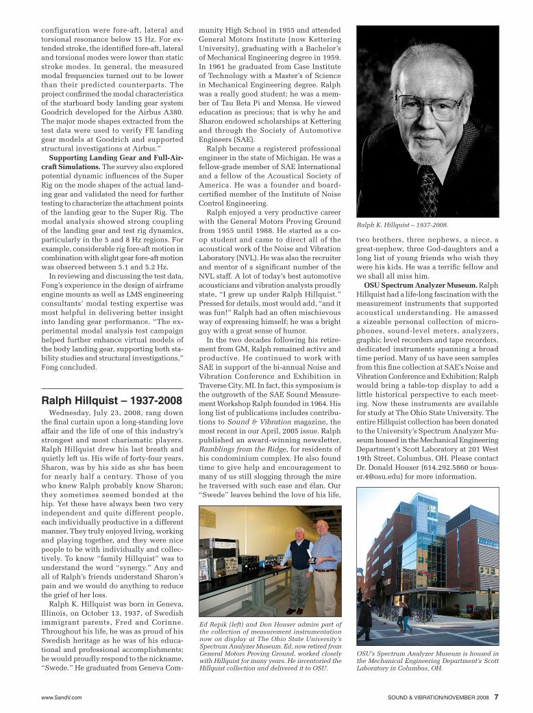
support a structural testing campaign to be performed on the starboard body landing gear system, Goodrich contracted with the U.S.-based team of LMS Engineering Ser-vices. “The LMS assignment involved EMA on a landing gear system, which allowed them to validate FE models of this rather complex mechanical assembly,” said Alvin Fong, manager of landing gear performance at Goodrich’s Oakville landing gear facility. “The six-wheel landing gear system weighs approximately 12,000 pounds, and its size exceeds 25 feet when fully extended. In landing gear system development, it is our task to meet the required stability and structural performance to ensure that the gear will safely react to all loads and cir-cumstances it will encounter throughout its service life.”
The structural test campaign for the A380 landing gear was performed at the Goodrich landing gear test facility in Oakville. The central feature of this facility is the “Super Rig,” an extremely large steel structure that encompasses nine test bays, each capable of handling an A380 body or wing gear. The entire Super Rig structure sits in a three-foot-deep pit approximately the size of two football fields. The body landing gear prototype to be subjected to the modal test campaign filled Bay No. 2 to the limit. The steel rig structure allowed the large-body landing gear to be suspended in free-free conditions. The test set-up also required LMS to fabricate two solid stands, each filled with 5,000 pounds of concrete. To avoid freeplay in landing gear joints as much as possible, LMS consultants pre-loaded the body landing gear unit with static forces that were applied vertically through bungee cords. The measurement instrumentation consisted of SCADAS 316 data acquisition systems as well as LMS Test.Lab software, including the LMS PolyMAX modal parameter estimator. The instrumentation also controlled the modal excitation systems.
Validating Modal Test Set-Up. To be able to provide sufficient energy while performing modal tests on a specimen of this size and weight, LMS engineering consultants installed multiple shakers. Two electro-dynamic shakers – each capable of generating 1,000 Newtons – were used to provide either burst-random or stepped-sine excitation. Initial modal tests showed that the test rig itself exhibited fundamental fore-aft motion around 5 and 8 Hz. As these dominant frequencies fell proximate to the 0-10 Hz frequency of interest for landing gear modal testing, significant dynamic coupling between gear modes and test rig modes were observed. To monitor this inter-ference throughout the test campaign, LMS
engineers added a number of measurement points to the modal test geometry of the landing gear assembly.
To verify the quality of the modal test set-up, LMS consultants evaluated auto-power spectra as well as frequency response functions (FRFs), coherence and reciprocity. These checks indicated whether all input energy is present at the output side and whether excitation and measurement points are located favorably. Auto-power spectra related to front and rear shaker excitation showed that both shaker inputs were of the same force level and excited all frequen-cies equally across the frequency range of interest. “When evaluating structural FRF coherence and reciprocity, the two-burst random shaker inputs created only limited nonlinear landing gear behavior in static stroke and extended positions at specified force levels between 5 and 15 Newtons,” Paul Weal, business development manager of LMS Engineering Services, explained. “However, when increasing force levels using stepped-sine excitation – 200 to 1,000 Newtons – we identified stronger nonlinear behavior, mainly as a result of slight back-lash that was present in the huge landing gear joint connections. When testing at highest force levels, the resulting bending and torsion modes became truly visible, as we witnessed displacements of about 1 inch. With the help of driving point FRF functions, we quantified the evolution of growing nonlinearity that is exhibited in response to increasing force levels.”
Selecting Landing Gear Modes. The ac-tual modal analysis test campaign started with the selection of the landing gear modes. LMS consultants quickly obtained insight into modal resonance through the sum-blocks function of LMS Test.Lab, which emphasizes modal resonance by dis-playing a summation of all measured FRFs. Based on the acquired data, the individual modal parameters were extracted using the innovative LMS PolyMAX curve fitter. The modal parameters then served as a basis to synthesize FRFs through calculation. The high level of correlation between measured and synthesized FRFs showed that the modal analysis was successful in accurately reproducing the measured FRFs.
Fong said, “The most significant modes retrieved for the landing gear static stroke
The six-wheel landing gear system weighs ap-proximately 12,000 pounds and is more than 25 feet long when fully extended.
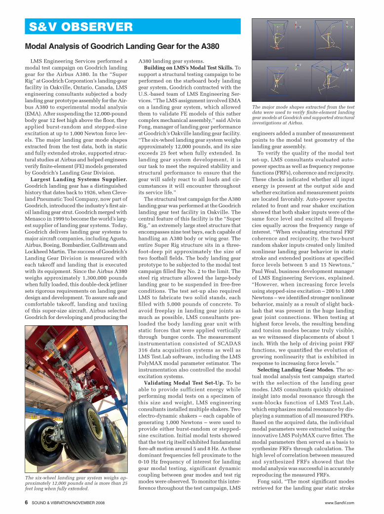
The major mode shapes extracted from the test data were used to verify finite-element landing gear models at Goodrich and supported structural investigations at Airbus.
www.SandV.com SOUND & VIBRATION/NOVEMBER 2008 7
configuration were fore-aft, lateral and torsional resonance below 15 Hz. For ex-tended stroke, the identified fore-aft, lateral and torsional modes were lower than static stroke modes. In general, the measured modal frequencies turned out to be lower than their predicted counterparts. The project confirmed the modal characteristics of the starboard body landing gear system Goodrich developed for the Airbus A380. The major mode shapes extracted from the test data were used to verify FE landing gear models at Goodrich and supported structural investigations at Airbus.”
Supporting Landing Gear and Full-Air-craft Simulations. The survey also explored potential dynamic influences of the Super Rig on the mode shapes of the actual land-ing gear and validated the need for further testing to characterize the attachment points of the landing gear to the Super Rig. The modal analysis showed strong coupling of the landing gear and test rig dynamics, particularly in the 5 and 8 Hz regions. For example, considerable rig fore-aft motion in combination with slight gear fore-aft motion was observed between 5.1 and 5.2 Hz.
In reviewing and discussing the test data, Fong’s experience in the design of airframe engine mounts as well as LMS engineering consultants’ modal testing expertise was most helpful in delivering better insight into landing gear performance. “The ex-perimental modal analysis test campaign helped further enhance virtual models of the body landing gear, supporting both sta-bility studies and structural investigations,” Fong concluded.
Wednesday, July 23, 2008, rang down the final curtain upon a long-standing love affair and the life of one of this industry’s strongest and most charismatic players. Ralph Hillquist drew his last breath and quietly left us. His wife of forty-four years, Sharon, was by his side as she has been for nearly half a century. Those of you who knew Ralph probably know Sharon; they sometimes seemed bonded at the hip. Yet these have always been two very independent and quite different people, each individually productive in a different manner. They truly enjoyed living, working and playing together, and they were nice people to be with individually and collec-tively. To know “family Hillquist” was to understand the word “synergy.” Any and all of Ralph’s friends understand Sharon’s pain and we would do anything to reduce the grief of her loss.
Ralph K. Hillquist was born in Geneva, Illinois, on October 13, 1937, of Swedish immigrant parents, Fred and Corinne. Throughout his life, he was as proud of his Swedish heritage as he was of his educa-tional and professional accomplishments; he would proudly respond to the nickname, “Swede.” He graduated from Geneva Com-
Ralph Hillquist – 1937-2008
munity High School in 1955 and attended General Motors Institute (now Kettering University), graduating with a Bachelor’s of Mechanical Engineering degree in 1959. In 1961 he graduated from Case Institute of Technology with a Master’s of Science in Mechanical Engineering degree. Ralph was a really good student; he was a mem-ber of Tau Beta Pi and Mensa. He viewed education as precious; that is why he and Sharon endowed scholarships at Kettering and through the Society of Automotive Engineers (SAE).
Ralph became a registered professional engineer in the state of Michigan. He was a fellow-grade member of SAE International and a fellow of the Acoustical Society of America. He was a founder and board-certified member of the Institute of Noise Control Engineering.
Ralph enjoyed a very productive career with the General Motors Proving Ground from 1955 until 1988. He started as a co-op student and came to direct all of the acoustical work of the Noise and Vibration Laboratory (NVL). He was also the recruiter and mentor of a significant number of the NVL staff. A lot of today’s best automotive acousticians and vibration analysts proudly state, “I grew up under Ralph Hillquist.” Pressed for details, most would add, “and it was fun!” Ralph had an often mischievous way of expressing himself; he was a bright guy with a great sense of humor.
In the two decades following his retire-ment from GM, Ralph remained active and productive. He continued to work with SAE in support of the bi-annual Noise and Vibration Conference and Exhibition in Traverse City, MI. In fact, this symposium is the outgrowth of the SAE Sound Measure-ment Workshop Ralph founded in 1964. His long list of publications includes contribu-tions to Sound & Vibration magazine, the most recent in our April, 2005 issue. Ralph published an award-winning newsletter, Ramblings from the Ridge, for residents of his condominium complex. He also found time to give help and encouragement to many of us still slogging through the mire he traversed with such ease and élan. Our “Swede” leaves behind the love of his life,
two brothers, three nephews, a niece, a great-nephew, three God-daughters and a long list of young friends who wish they were his kids. He was a terrific fellow and we shall all miss him.
OSU Spectrum Analyzer Museum. Ralph Hillquist had a life-long fascination with the measurement instruments that supported acoustical understanding. He amassed a sizeable personal collection of micro-phones, sound-level meters, analyzers, graphic level recorders and tape recorders, dedicated instruments spanning a broad time period. Many of us have seen samples from this fine collection at SAE’s Noise and Vibration Conference and Exhibition; Ralph would bring a table-top display to add a little historical perspective to each meet-ing. Now these instruments are available for study at The Ohio State University. The entire Hillquist collection has been donated to the University’s Spectrum Analyzer Mu-seum housed in the Mechanical Engineering Department’s Scott Laboratory at 201 West 19th Street, Columbus, OH. Please contact Dr. Donald Houser (614.292.5860 or [email protected]) for more information.
Ralph K. Hillquist – 1937-2008.
Ed Repik (left) and Don Houser admire part of the collection of measurement instrumentation now on display at The Ohio State University’s Spectrum Analyzer Museum. Ed, now retired from General Motors Proving Ground, worked closely with Hillquist for many years. He inventoried the Hillquist collection and delivered it to OSU.
OSU’s Spectrum Analyzer Museum is housed in the Mechanical Engineering Department’s Scott Laboratory in Columbus, OH.