Mobile Networks - Aalto · Mobile Networks Prof. Jukka K. Nurminen Department of Computer Science...
45
Mobile Networks Prof. Jukka K. Nurminen Department of Computer Science and Engineering, Aalto University T-110.5121 Mobile Cloud Computing Fall 2013
Transcript of Mobile Networks - Aalto · Mobile Networks Prof. Jukka K. Nurminen Department of Computer Science...

Mobile Networks
Prof. Jukka K. Nurminen Department of Computer Science and Engineering, Aalto University T-110.5121 Mobile Cloud Computing Fall 2013

Lecture Contents
• Target: provide an overview of the operation of mobile networks – in particular 3G cellular
• Cellular network – Challenges arising in cellular communication – Basic structure and architecture – Key mechanisms: mobility management, call formation, handover
• Data transfer in cellular networks – GPRS, UMTS, LTE
• Issues relevant for mobile cloud computing – Energy efficiency

Challenges in Mobile Environments
• Limitations of the Wireless Network • packet loss due to transmission errors • variable capacity links • limited communication bandwidth • Broadcast nature of the communications
• Limitations Imposed by Mobility • To form connection to a user • To maintain connection while the user moves
• Limitations of the Handheld device
• short battery lifetime • limited capacities

History
ARP NMT
GSM (2G) 1993
GPRS (2.5G) 2001
3G 1999
LTE 2009
4
Faster data rates; towards global standards; smaller, lighter, smarter, …, terminals
Analog Digital

Basic structure and operation of GSM network
Partly adapted from: Computer Networking: A Top Down Approach 5th edition. Jim Kurose, Keith Ross Addison-Wesley, April 2009.
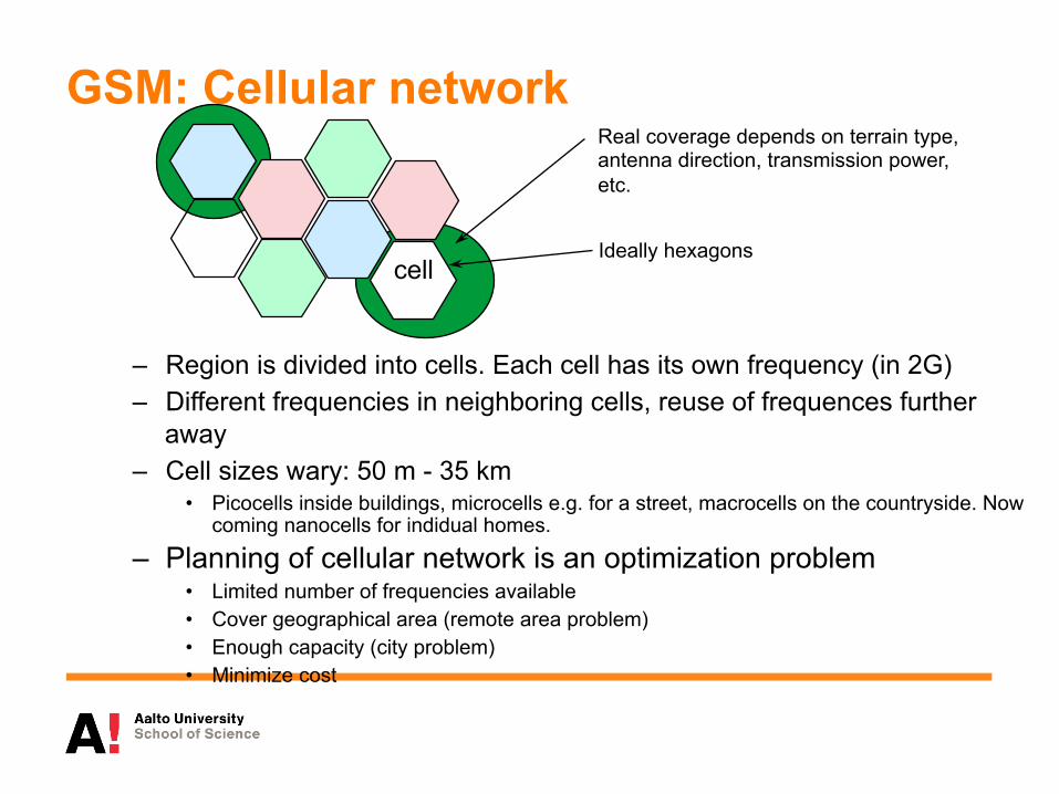
Real coverage depends on terrain type, antenna direction, transmission power, etc.
Ideally hexagons cell
GSM: Cellular network
– Region is divided into cells. Each cell has its own frequency (in 2G) – Different frequencies in neighboring cells, reuse of frequences further
away – Cell sizes wary: 50 m - 35 km
• Picocells inside buildings, microcells e.g. for a street, macrocells on the countryside. Now coming nanocells for indidual homes.
– Planning of cellular network is an optimization problem • Limited number of frequencies available • Cover geographical area (remote area problem) • Enough capacity (city problem) • Minimize cost

Example of cell coverage
7

GSM Architecture
Mobile station (MS), SIM-card
Base station (BTS)
Base station controller (BSC)
Mobile switching center (MSC), Visitor location register (VLR) Home location register
(HLR)
Gateway- MSC (GMSC)
PSTN
Base station subsystem (BSS) Network subsystem (NSS)
Equipment identification register (EIR)
Authentication center (AuC)

6: Wireless and Mobile Networks
6-9
Mobile Switching
Center
Public telephone network, and Internet
Mobile Switching
Center
Components of cellular network architecture
q connects cells to wide area net q manages call setup q handles mobility
MSC
q covers geographical region q base station (BS) analogous to 802.11 AP q mobile users attach to network through BS q air-interface: physical and link layer protocol between mobile and BS
cell
wired network

6: Wireless and Mobile Networks
6-10
Public switched telephone network
mobile user
home Mobile
Switching Center
HLR home network
visited network
correspondent
Mobile Switching
Center
VLR
GSM: indirect routing to mobile
1 call routed to home network
2
home MSC consults HLR, gets roaming number of mobile in visited network
3
home MSC sets up 2nd leg of call to MSC in visited network
4
MSC in visited network completes call through base station to mobile

6: Wireless and Mobile Networks
6-11
Mobile Switching
Center
VLR
old BSS new BSS
old routing
new routing
GSM: handoff with common MSC
• Handoff goal: route call via new base station (without interruption)
• reasons for handoff: – stronger signal to/from new BSS
(continuing connectivity, less battery drain)
– load balance: free up channel in current BSS
– GSM doesn’t mandate why to perform handoff (policy), only how (mechanism)
• handoff initiated by old BSS

6: Wireless and Mobile Networks
6-12
Mobile Switching
Center
VLR
old BSS
1
3
2 4
5 6
7 8
GSM: handoff with common MSC
new BSS
1. old BSS informs MSC of impending handoff, provides list of 1+ new BSSs
2. MSC sets up path (allocates resources) to new BSS
3. new BSS allocates radio channel for use by mobile
4. new BSS signals MSC, old BSS: ready 5. old BSS tells mobile: perform handoff to
new BSS 6. mobile, new BSS signal to activate new
channel 7. mobile signals via new BSS to MSC:
handoff complete. MSC reroutes call 8 MSC-old-BSS resources released

SMS text messaging service
13
• SMC (short message center) stores and forwards the text messages • Detection of phone location in the same way as in call formation

Mobile data
15
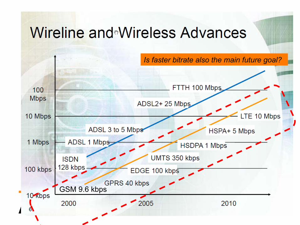
GSM 9.6 kbps
Is faster bitrate also the main future goal?

Targets for cellular data transfer
• High bit rate • Low latency • Efficient use of resources when transferring data (which
in many cases is bursty) • Billing based on amount of data (instead of time
connected) • Small resource requirements for mobile and small
energy consumption

GPRS
MS BTS BSC
MSC, VLR
HLR
GMSC
PSTN
SGSN GGSN
Internet

New GPRS elements • Serving GPRS Support Node (SGSN) is a router
– Keeps track of mobile location – Forwards the traffic – Handles billing – Identifies mobile and executes other management
activities • Gateway GPRS Support Node (GGSN)
– Forwards traffic to other networks, in particular IP-packets to Internet
– Allocates IP address to mobile • IP address does not change even if user moves
• Utilizes the GSM mechanisms such as VLR ja HLR

GSM radio interface
• Combination of FDMA (Frequency Division Multiple Access) ja TDMA (Time Division Multiple Access)
• Each cell has fixed frequency • Each call uses negotiated timeslots
• Problem for fast data transfer: more timeslots would be needed but only for the duration of the databurst
Frequencies (per cell)
Timeslots (per call)
Speed: 9.6 kbps

GPRS: Dynamic allocation of time slots -> more speed
• Takes a number of free timeslots into use when there are packets in the queue (e.g. 50 kbit/s with 4 timeslots)
• Dynamic allocation and freeing of timeslots – Voice has priority
Overview_CellularMobileSystems.ppt 21
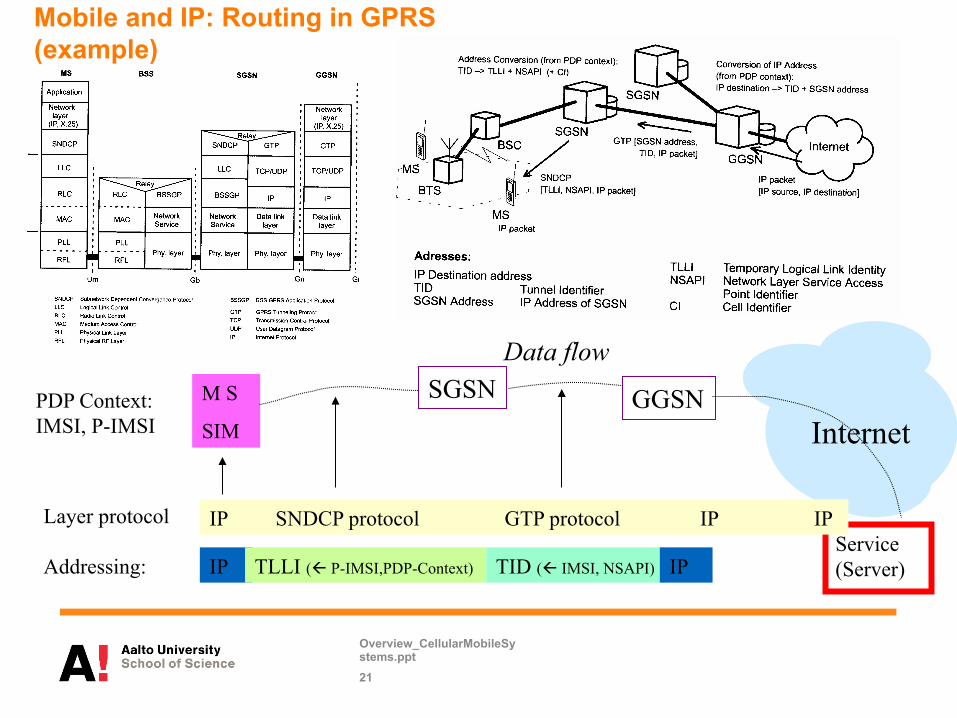
Mobile and IP: Routing in GPRS (example)
M S
SIM
SGSN GGSN Internet
PDP Context: IMSI, P-IMSI
Data flow
Addressing: IP TLLI (ß P-IMSI,PDP-Context) TID (ß IMSI, NSAPI) IP
Layer protocol Service (Server)
IP SNDCP protocol GTP protocol IP IP

EDGE • Enhanced Data rate for GSM Evolution • Like GPRS but faster with new modulation
– 40 kbps -> 115 kbps – Data rates depend on context (other users, distance from
basestation)

Modulation change
• 1 bit per symbol -> 3 bits per symbol
Overview_CellularMobileSystems.ppt 23
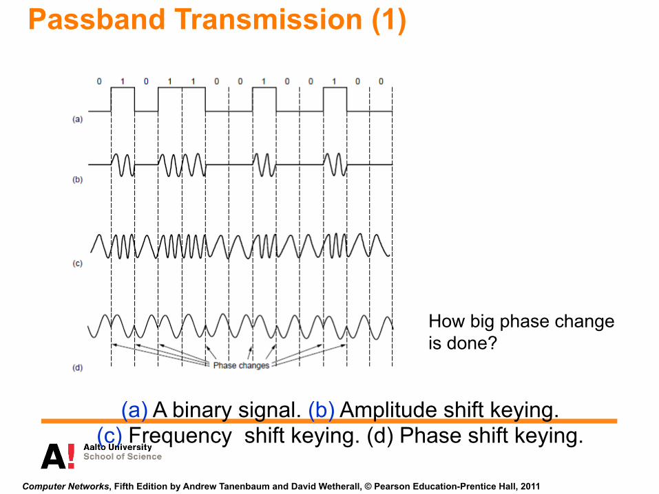
Passband Transmission (1)
(a) A binary signal. (b) Amplitude shift keying. (c) Frequency shift keying. (d) Phase shift keying.
Computer Networks, Fifth Edition by Andrew Tanenbaum and David Wetherall, © Pearson Education-Prentice Hall, 2011
How big phase change is done?

UMTS (3G)
• Universal Mobile Telecommunications System – Also known as 3G
• Still higher data rates than in GSM/GPRS/EDGE • Data transfer with 2 Mb/s • In practice often much less
• More efficient utilization of radio resources with WCDMA technology

UMTS
MS BTS BSC MSC, VLR
HLR
GMSC
PSTN GERAN
SGSN GGSN
Internet
UE BS RNC
UTRAN
Circuit switched
Packet switched

6-27
UMTS radio interface • CDMA, Code Division Multiple Access • All base stations use the same
frequency • Each user has his own code • When codes are properly selected
multiple transmissions at the same time at the same frequency are possiblem
• One bit is coded into multiple symbols which the receiver of the proper code is able to detect from background noise
CN Node B RNC
Node B UE

GSM vs. UMTS radio interface
Timeslots (per call)
GSM Each person at a different time Each base station (in a region) with a different frequency
UMTS Everybody at the same time Wide channel => high bitrate (Nyquist formula)
5MHz
0.2 MHz

6: Wireless and Mobile Networks
6-29
CDMA Encode/Decode
slot 1 slot 0
d1 = -1
1 1 1 1
1 - 1 - 1 - 1 -
Zi,m= di.cm
d0 = 1
1 1 1 1
1 - 1 - 1 - 1 -
1 1 1 1
1 - 1 - 1 - 1 -
1 1 1 1
1 - 1 - 1 - 1 -
slot 0 channel output
slot 1 channel output
channel output Zi,m
sender code
data bits
slot 1 slot 0
d1 = -1 d0 = 1
1 1 1 1
1 - 1 - 1 - 1 -
1 1 1 1
1 - 1 - 1 - 1 -
1 1 1 1
1 - 1 - 1 - 1 -
1 1 1 1
1 - 1 - 1 - 1 -
slot 0 channel output
slot 1 channel output receiver
code
received input
Di = Σ Zi,m.cm m=1
M
M

6: Wireless and Mobile Networks
6-30
CDMA: two-sender interference

Overview_CellularMobileSystems.ppt 31
CDMA – Why it makes sense?
• Symbol speed (chip rate) 3.84 Mchip/s • Number of available code 512, if 512 symbols are used to transfer
a bit – Then bitrate1.7 kbit/s (too slow even for voice)
• Faster speeds by having smaller number of symbols per bit • 256 symbols -> 5.51 kbit/s (voice) • 8 symbols -> 384 kbit/s
• The smaller the symbol the less simulateous users – 8 symbols/bit => 7 users – 256 symbols/bit => 255 users
• The systems adjusts the allocation of symbols based on user number and data transfer needs

32
HSDPA (3.5G) • High Speed Downlink Packet Access • 1.8, 3.6, 7.2 and 14.4 Mbit/s (42 & 84 Mbit/s with
HSPA+) • A step back to time division
– In UMTS each user has his own code – In HSDPA a number of users have the same code but traffic is
divided in different time points • High Speed Downlink Shared Channel • The system dynamically schedules the shared channel use
– Other improvements in latency, acknowledgements, modulation, etc

LTE
• Only packet data (Voice ->VoIP) • Less network elements (RNC level removed) • Applies many new radio and antenna techniques
(OFDM, MIMO) • First test networks in use
– No phones, only data dongles (in Finland, phones also in US, Korea, and some other countries)
33

34
LTE radio interface • Increasing the chip rate in
WCDMA is difficult because of multipath propagation (signals reaching phone through different paths come at different times
• Based OFDMA (Orthogonal Frequency-Division Multiple Access) teknology – Whole channel distributed to
narrow subchannels – Multiple subchannels used in
parallel for faster bitrate – Different users transfer data at
different times
• Multipath propagation

LTE Architecture

36

37
New services with UMTS
Typical average bitrate
Better network performance
UMTS/HSDPA 1-2
Mbps
UMTS 384
kbps
EGPRS 80-160 kbps
GPRS 30-40 kbps
GSM 10-40 kbps
Video telephony Real-time IP multimedia
WEB browsing Corporate data access
xHTML browsing
Multitasking
3G-services utilises bigger speed and/or QoS
Some services work in all networks Multicasting
Broadband in wide area
Streaming audio/video
Voice & SMS Presence/location
xHTML browsing Application downloading E-mail
MMS picture / video
LTE
16-150 Mbps

Remember that there are other radios than cellular • WLAN • Bluetooth
– Bluetooth low energy (BLE)
• RFID – Near field communication
• WiMax • ZigBee
Present now or near future in mobile phones

To Read More
• Computer Networking: A Top Down Approach Featuring the Internet (5th ed.), J.F. Kurose and K.W. Ross, Addison-Wesley Longman – 6.2 CDMA – 6.4 Cellular internet access – 6.7 Managing mobility in cellular
networks • From GSM to LTE, Martin Sauter,
John Wiley & Sons Inc • Courses at electrical engineering
department at Aalto
39

Energy efficiency

High exponential growth of most resources – except battery capacity
0
2000
4000
6000
8000
10000
12000
14000
16000
1998 2000 2002 2004 2006 2008 2010 2012
Laskentateho
Internet kaistanleveys PC kovalevy
Akkukapasiteetti
CPU
Internet bandwidth
PC harddisk
Battery capacity

Power consumption of streaming in 3G phone
2011-09-27 Jukka K. Nurminen
42
Neuvo, Y., "Cellular phones as embedded systems," Solid-State Circuits Conference, 2004. Digest of Technical Papers. ISSCC. 2004 IEEE International , vol., no., pp. 32-37 Vol.1, 15-19 Feb. 2004

Higher bit rate -> more energy-efficient Energy consumption as a function of bit rate
0 0.005 0.01 0.015 0.02 0.025 0.03 0.035 0.04 0.045 0.05
25 50 75 100 125 150 175 200 225 250 275 300 kB/s
mJ/bit WLAN 3G
43 2011-09-27 Jukka K. Nurminen

Communication Same average bitrate different traffic pattern
0.99W 0.53W

3G Energy Consumption (Tail energy problem)
2011-09-27 Jukka K. Nurminen
• Data transfer in DCH (dedicated channel) state • After data transfer is complete it takes seconds to return to idle state. The actual depends on your cellular operator (e.g. Elisa 2s+2s, some US operator 12.5s)