
Mobile Jumper Manual v2 03 - Extreme Engineering
69
Mobile Jumper Owner’s Manual o EJ-JM4-MM4-01 – Monkey Motion II 4 Station Jumper o EJ-JM4-EIL-01 – Extreme In-Line 4 Station Jumper Mobile Jumper Owner’s Manual © 2010, 2011, 2012 Extreme Engineering® All Rights Reserved
Transcript of Mobile Jumper Manual v2 03 - Extreme Engineering

Mobile Jumper Owner’s Manual
o EJ-JM4-MM4-01 – Monkey Motion II 4 Station Jumper o EJ-JM4-EIL-01 – Extreme In-Line 4 Station Jumper
Mobile Jumper Owner’s Manual ©
2010, 2011, 2012 Extreme Engineering®
All Rights Reserved

Version 2.02 – 09/27/11
Extreme Engineering®
Mobile Jumper Owner’s Manual
Page 2 of 69
Extreme Engineering 9198-B Ridge Road Newcastle, CA 95658 Voice: 916-663-1560 Fax: 916-663-9249 e-mail: [email protected] Website: www.extremeengineering.com Revision 2.03 June 2012 © 2010, 2011, 2012 Extreme Engineering® All Rights Reserved This manual is the property of Extreme Engineering. Any duplication without Extreme Engineering consent is illegal. If you have any questions about the manual, please contact Extreme Engineering. Extreme Engineering® is a US registered trademark of Extreme Engineering®. US PAT# 6,083,142, 6,390,952 and patents pending US Patents and Patents Pending. Extreme Auto-belay™, Belay in the Box™, PowerBelay™, Space Saver™, C.A.T.T.™, Monkey Motion™, Angel Auto-belay™, Speed Harness™, Quad Pod™ and Extreme Air™ are trademarks of Extreme Engineering®.

Version 2.02 – 09/27/11
Extreme Engineering®
Mobile Jumper Owner’s Manual
Page 3 of 69
Congratulations! Congratulations on your purchase of an Extreme Engineering Mobile Jumper product. Your Mobile Jumper has been designed and engineered by the company who invented and innovated numerous recreational equipment products including: mobile and stationary climbing walls, the Extreme Auto-belayTM safety climbing system, the PowerBelayTM safety rappelling system and Jumper systems. Your Mobile Jumper is the best in the industry! Extreme Engineering® Jumper products are designed with safety, ease of operation and durability built in. It will provide you with years of service. Your Mobile Jumper is easy to tow, set up, operate and take down. If you follow these instructions carefully and completely, you’ll be assured of safe and reliable operation.
READ AND FOLLOW ALL SAFETY INSTRUCTIONS IN THIS MANUAL.

Version 2.02 – 09/27/11
Extreme Engineering®
Mobile Jumper Owner’s Manual
Page 4 of 69
Mobile Monkey Motion II Jumper
Extreme In-Line Jumper

Version 2.02 – 09/27/11
Extreme Engineering®
Mobile Jumper Owner’s Manual
Page 5 of 69
Table of Contents To go to a particular section click on the section title.
1. Safety first! Read Before Proceeding......................... 1.1. Safety Rules............................................... 2. Pre-Travel Checklist......................................... 2.1. Tow Vehicle Safety Check................................... 2.2. Jumper Safety Check........................................ 3. Prepare For Towing........................................... 3.1. Attach Jumper To Tow Vehicle............................... 3.2. Pre-Travel Safety Inspection Details.......................
4. Jumper Setup................................................. 4.1. Position The Jumper........................................ 4.2. Unhitch Tow Vehicle........................................
5. Prepare For Operating The Jumper............................. 5.1. Stabilizer Arms/Jacks...................................... 5.2. Jumper Poles............................................... 5.3. Jumper Pole Spreader Bars.................................. 5.4. Jumper Pole Slings......................................... 5.5. Inflatable Jump Pads....................................... 5.6. Turn On Lift Pump.......................................... 5.7. Flyer Jump Harness ........................................ 6. Operating The Jumper......................................... 6.1. Preparing The Jumping Participant.......................... 6.2. Raising The Jumping Participant............................ 6.3. Lowering The Jump Participant..............................
7. Suggested Operating Techniques............................... 8. Safety Rules For The Operators............................... 9. Safety Rules For Your Jumping Participants................... 10. Special Jumping Participant Situations..................... 10.1. Participant Becomes Frozen During Jumping Session......... 10.2. Participant Reports Discomfort With Harness............... 10.3. Participant Is Intentionally Reckless..................... 10.4. Participant Is Too Light To Achieve Jumping Motion........
88
101010
101116
232323
2525282930303537
42424243
44
45
45
4747474748
Version 2.02 – 09/27/11
Extreme Engineering®
Mobile Jumper Owner’s Manual
Page 6 of 69
Table of Contents (cont.)
To go to a particular section click on the section title. 11. Additional Jumper Situations............................... 11.1. Forgot To Attach Jumper Pole Slings To Jump Poles......... 11.2. Hydraulic Lift Stops Operating With Participant Suspended
In Air.................................................... 11.3. Emergency Shutoff.........................................
12. End Of Event Takedown...................................... 13. Troubleshoot............................................
14. Maintenance................................................ 15. Cleaning And Other Special Care............................ 15.1. Protection From The Elements..............................
16. Checklists And Log......................................... 16.1. Per-Use Maintenance....................................... 16.2. Periodic Maintenance...................................... 17. Inspection/Maintenance Checklists.......................... 17.1. Maintenance Log........................................... 18. Safe Towing Tips........................................... 19. Specifications............................................. 19.1. Mobile Monkey Motion II Jumper Specifications............. 19.2. Extreme In-Line Jumper Specifications..................... 19.3. Steel Framing And Weld Specifications..................... 19.4. Hydraulic Lift Pump Specifications........................ 19.5. Inflatable Blower Specifications.......................... 19.6. Portable Generator Specifications......................... 19.7. Jump Participant Limits................................... 19.8. Operational Limits........................................ 19.9. Jump Pad Tethering........................................ 20. Limited Warranty........................................... 20.1. Warranty Claim............................................ 21. Replacement Parts.......................................... 22. Technical Support.......................................... Warranty Claim Form............................................
4848
4850 50
51
52
5454
555555
5760
61
62626363646464646464
6566
66
67
68

Version 2.02 – 09/27/11
Extreme Engineering®
Mobile Jumper Owner’s Manual
Page 7 of 69
Version Update Information 2.03 June 20, 2012
Updated Replacement poles to every 2 years. Connection tubes for inflatable pads may not be required during setup.
2.02 September 27, 2011
Added part must be replaced if any of the inspection items to look for are found.
2.01 May 18, 2011 Final modifications for Extreme In-Line product.
2.00 April 21, 2011 Added Extreme In-Line product.
1.05 October 29, 2010 Modifications to meet the state of New Jersey product certification requirements.
1.04 September 15, 2010 Added inflatable pad hold down strap and windy condition instructions..
1.03 July 13, 2010 Added flyer harness leg padding adjustment instructions.
1.02 July 9, 2010 Added standard buckle flyer harness instructions.
1.01 July 7, 2010 Minor update to flyer harness instructions.
1.00 July 1, 2010 Original release.

Version 2.02 – 09/27/11
Extreme Engineering®
Mobile Jumper Owner’s Manual
Page 8 of 69
1. Safety first! Read Before Proceeding WARNING: This is a safety alert symbol. It is used to inform of potential safety hazards or risks. Read all safety information which has this symbol next to it to avoid injury or death. Always make safety your number one priority when setting up, operating, and taking down your Jumper. 1.1. Safety Rules WARNING: For your safety, read and follow all safety rules and safety instructions in this Owner’s Manual before operating your Jumper. WARNING: Do Not set up or operate the Jumper near overhead electrical lines, roof eaves, trees, or other overhead obstructions or hazards. Allow a minimum of 26 feet for clearance.
WARNING: Do Not set up or operate the Jumper in windy conditions. On non-smooth concrete surfaces, do not operate with winds or wind gusts greater than or equal to 30 mph (48.28 km/h). On smooth concrete surfaces, do not operate with winds or wind gusts greater than or equal to 15 mph (24.14 km/h).
WARNING: Set Up and operate the Jumper only on a level surface, no more than 1% grade.

Version 2.02 – 09/27/11
Extreme Engineering®
Mobile Jumper Owner’s Manual
Page 9 of 69
WARNING: Set Up and operate the Jumper only on solid surfaces. Extend the jacks onto solid surfaces only. WARNING: Do Not climb on the poles or pole supports. Do Not stand on top of the poles or supports.
WARNING: Although it is possible to set up the Jumper by a single operator, Extreme Engineering recommends a second operator to help with setup. This second operator can look for and warn of potential issues or hazards that may not be seen by one operator. As well, the jumper poles are long and heavy. Two persons can insert them and remove them from the lift tubes easier and safer than one person. WARNING: Keep the area clear of people, cars, etc. during setup, operation and takedown. Do Not walk under or allow anyone to walk under the jumper poles while they are in use, being raised or lowered. WARNING: Do Not allow anyone to climb anywhere on the Jumper or jumper poles. All jumping participants must be harnessed and the harness attached to the pole slings with the carabiners at all times during their jump time. WARNING: Inspect the Jumper before use each day it is operated. The Maintenance Section of this User’s Guide includes comprehensive details for making a complete inspection. Read that section carefully. If you find any problems during the inspection which you cannot resolve, Do Not operate the Jumper until the problem is corrected. Visit Extreme Engineering’s technical support web site at www.extremeengineering.com or contact Extreme Engineering’s Technical Support at 916-663-1560 for help in resolving issues or concerns.

Version 2.02 – 09/27/11
Extreme Engineering®
Mobile Jumper Owner’s Manual
Page 10 of 69
2. Pre-Travel Checklist WARNING: For your safety, read all towing instructions before towing the Jumper. 2.1. Tow Vehicle Safety Check Check the air pressure in all tires including spare tire. Check for sufficient tread depths
and tire damage on all tires. Check fuel and oil levels. Check dash gauges and warning lights with key on without engine running and with
engine running. Check that all promotional items (e.g. lights, displays) are secure and travel ready. Check the tow hitch and tow ball for proper attachment and tightness on the towing
vehicle per the tow hitch manufacturer’s specifications Check tow ball for proper size (must be 2-5/16”) and for abnormal wear. Ensure the weight limits of the vehicle’s tow hitch is greater than the total load weight
and tongue weight of the Jumper. Ensure the towing capacity of the tow vehicle is greater than the weight of the Jumper.
2.2. Jumper Safety Check Check the tow coupler mounting bolts for proper tightness. Check the tow coupler for damage or unusual wear. Check the jumper pole travel lockdown pins are in place for towing with a hitch pin
through the hole at the end of each jumper pole lockdown pin. Check all tires (including spare tire if equipped) for proper air pressure. Check tires for legal tread wear depth. Check wheel lug nuts for proper tightness. Check the hydraulic pump for proper oil level. Check for oil leaks on all hydraulic hoses and fittings. Note: There may be oil residue
found at the fill cap area of the lift pump oil reservoir tank. The fill cap is a breather cap and may allow a small amount of oil to escape from the tank during travel.
Check for grease at all lift tube hinges where the lift tube assemblies attach to the jumper base frame.
Inspect the jumper poles for damage. Look for and remove any debris caught in and around the trailer. Remove wheel blocks for departure.
3. Prepare For Towing WARNING: For your safety, read all instructions before attaching the Jumper to the tow vehicle. Extreme Engineering recommends a solid Tow Hitch Receiver for towing the Jumper. Ensure the solid receiver is properly inserted and attached per the tow hitch manufacturer’s specifications and requirements. Check the tow hitch and tow ball for proper attachment and tightness on the tow hitch per the hitch manufacturer’s specifications.

Version 2.02 – 09/27/11
Extreme Engineering®
Mobile Jumper Owner’s Manual
Page 11 of 69
Ensure vehicle towing capacity and the tow hitch limits are greater than the total weight and tongue weight of the Jumper. Check towing ball for proper size (2-5/16”) and for abnormal wear. WARNING: Do Not tow the Jumper without the proper size tow ball. The tow ball must be a 2-5/16” diameter ball. A ball smaller in diameter will allow the Jumper to disconnect from the tow vehicle, even with the coupler locking latch and safety pin in place during towing.
Mobile Monkey Motion II Extreme In-Line Towing Components Towing Components
3.1. Attach Jumper To Tow Vehicle Back the tow vehicle into position so the tow ball is positioned under the Jumper’s coupler. If you have a second operator, have him or her stand by the trailer to guide you into position. Position the tow vehicle’s hitch as close as possible to the coupler of the Jumper trailer with the coupler directly above the tow ball as possible. Position the vehicle to prevent manually moving the trailer into place for attachment to the tow vehicle. WARNING: Avoid having to manually position the trailer. Do Not attempt to move the trailer by hand as this could result in serious injury. Lower the coupler down onto the tow ball once the tow vehicle’s tow ball is properly aligned with the coupler. Using the front jack mounted to the tongue, turn the jack handle counter clockwise until the coupler is fully engaged over the tow ball. Continue to turn the jack handle until the foot of the jack is clear of the ground and can be rotated 90 degrees to its travel position.

Version 2.02 – 09/27/11
Extreme Engineering®
Mobile Jumper Owner’s Manual
Page 12 of 69
Lower the Coupler Latch Handle to the fully down position. Ensure the Latch Handle Safety Lock inserts into its locking slot on the coupler body underneath the latch handle. If the latch is in it’s proper position, you should not be able to lift the latch handle straight up. Locate the Safety Hitch Pin through the hole on the side of the coupler and latch handle. Ensure the hitch pin spring clip is slipped over the end of the hitch pin to prevent it from dislodging during travel.

Version 2.02 – 09/27/11
Extreme Engineering®
Mobile Jumper Owner’s Manual
Page 13 of 69
Mobile Monkey Motion II
Extreme In-Line
WARNING: Do Not tow the Jumper without the latch handle in the locked position and the safety hitch pin properly in place.

Version 2.02 – 09/27/11
Extreme Engineering®
Mobile Jumper Owner’s Manual
Page 14 of 69
Attach the two Towing Safety Cables/Chains to the tow vehicle’s hitch.
WARNING: Do Not tow the Jumper without the safety towing cables/chains properly attached to the towing vehicle. Attach the Electrical Plug from the Jumper to the towing vehicle. The Mobile Monkey Motion II uses a 4-way flat plug to connect the lights to the tow vehicle. Ensure the plug is fully inserted into the tow vehicle’s electrical socket.
The Extreme In-Line uses a 7-way plug to connect the lights and brakes to the towing vehicle. Ensure the plug is fully inserted into the tow vehicle’s electrical socket.

Version 2.02 – 09/27/11
Extreme Engineering®
Mobile Jumper Owner’s Manual
Page 15 of 69
WARNING: Do Not tow the Jumper without the electrical plug attached to the towing vehicle. Verify operation of tow vehicle and Jumper lights. The Jumper tail lights should be on when the tow vehicle’s parking light or headlight switch is in the on position. The Jumper brake lights operate when the tow vehicle’s brake pedal is depressed. Both of the Jumper brake lights will flash when the tow vehicle’s 4-way emergency switch is turned on. The Jumper left and right turn signals should operate with the respective left and right turn signals of the tow vehicle. WARNING: Do Not tow the Jumper without operational tail lights, brake lights and turn signal lights. Extreme In-Line Only - Attach the Emergency Brake Break-a-way Lanyard to the tow vehicle. This is not applicable for the Mobile Monkey Motion II. The lanyard must be attached to the tow vehicle, not the towing safety chain. Ensure the emergency brake break-a-way switch pull tab is fully inserted into the break-a-way switch.
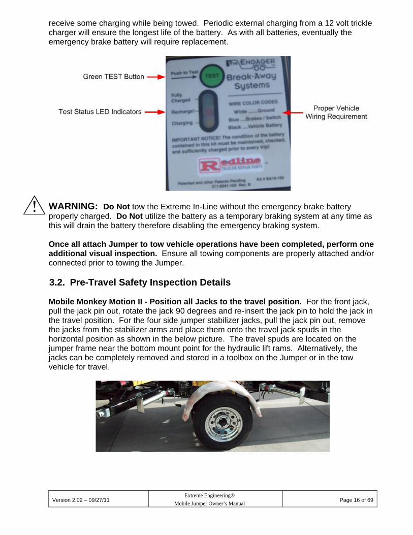
WARNING: Do Not tow the Extreme In-Line without the emergency brake lanyard attached (not applicable on the Mobile Monkey Motion II). Extreme In-Line Only – Verify Condition of Emergency Brake Battery. This is not applicable for the Mobile Monkey Motion II. Should the trailer become disconnected from the tow vehicle trailer hitch during travel, the emergency brake lanyard will pull the tab out of the emergency break-a-way switch. When the tab is pulled out of the break-a-way switch, the battery will actuate the brakes on the trailer, causing the brakes to be applied, to assist in stopping a potential runaway trailer. Verify the condition of the battery by pressing the green TEST button on the battery cover. Look at the three different colored LEDs to determine the condition of the battery. Pressing the green TEST button will determine when the battery will require additional external charging as indicated by the three different colored test LED lights. If you have a properly wired 7-way towing harness on the tow vehicle with the 12 volt accessory wire in operation on the vehicle side of the 7-way electrical plug, the battery will
Version 2.02 – 09/27/11
Extreme Engineering®
Mobile Jumper Owner’s Manual
Page 16 of 69
receive some charging while being towed. Periodic external charging from a 12 volt trickle charger will ensure the longest life of the battery. As with all batteries, eventually the emergency brake battery will require replacement.
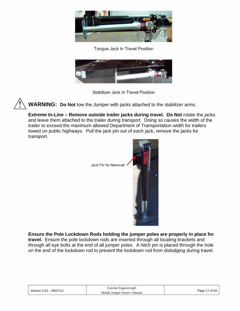
WARNING: Do Not tow the Extreme In-Line without the emergency brake battery properly charged. Do Not utilize the battery as a temporary braking system at any time as this will drain the battery therefore disabling the emergency braking system. Once all attach Jumper to tow vehicle operations have been completed, perform one additional visual inspection. Ensure all towing components are properly attached and/or connected prior to towing the Jumper. 3.2. Pre-Travel Safety Inspection Details Mobile Monkey Motion II - Position all Jacks to the travel position. For the front jack, pull the jack pin out, rotate the jack 90 degrees and re-insert the jack pin to hold the jack in the travel position. For the four side jumper stabilizer jacks, pull the jack pin out, remove the jacks from the stabilizer arms and place them onto the travel jack spuds in the horizontal position as shown in the below picture. The travel spuds are located on the jumper frame near the bottom mount point for the hydraulic lift rams. Alternatively, the jacks can be completely removed and stored in a toolbox on the Jumper or in the tow vehicle for travel.
Version 2.02 – 09/27/11
Extreme Engineering®
Mobile Jumper Owner’s Manual
Page 17 of 69
WARNING: Do Not tow the Jumper with jacks attached to the stabilizer arms. Extreme In-Line – Remove outside trailer jacks during travel. Do Not rotate the jacks and leave them attached to the trailer during transport. Doing so causes the width of the trailer to exceed the maximum allowed Department of Transportation width for trailers towed on public highways. Pull the jack pin out of each jack, remove the jacks for transport.
Ensure the Pole Lockdown Rods holding the jumper poles are properly in place for travel. Ensure the pole lockdown rods are inserted through all locating brackets and through all eye bolts at the end of all jumper poles. A hitch pin is placed through the hole on the end of the lockdown rod to prevent the lockdown rod from dislodging during travel.

Version 2.02 – 09/27/11
Extreme Engineering®
Mobile Jumper Owner’s Manual
Page 18 of 69
Mobile Monkey Motion II
Extreme In-Line
Ensure the stabilizer arms are in the travel position. The stabilizer arms are to be pushed all the way into the jumper base until the spring loaded pop-pin drops down into the hole to prevent the arms from extending out during travel. Pull out the pop-pin to allow the stabilizer arm to be pushed in to the travel position. Release the pop-pin after sliding the arm in a few inches from the operational position. Continue to slide the stabilizer arm all the way in until the pop-pin engages the arm in the travel position, If the pop-pin is in the proper position, you will be unable to push or pull the arm from its locked position for travel.

Version 2.02 – 09/27/11
Extreme Engineering®
Mobile Jumper Owner’s Manual
Page 19 of 69
WARNING: Do Not tow the Jumper without the stabilizer arms and pop-pins in place to prevent the stabilizer arms from extending out during travel. Inspect all Wheel Lug Nuts, Tire Pressures and Tread Depths, Hub Dust Caps and Suspension. The wheel lug nuts are to be torqued to 90 psi (pounds per square inch). For factory supplied tires, the tire air pressure should be 50 psi with a cold tire. Always
check the tire air pressure with a cold tire. A tire that has been driven can increase up to 4 psi or more when hot. If you no longer have factory tires or exact factory replacement tires, use the recommended tire pressure imprinted on the side of the tire for proper inflation requirements. If you are not sure what the tire air pressure should be on your tires, any local tire shop can help determine what that pressure should be.
Check all tire tread depths for equal to or exceeding required tread depths. There are tire wear tread indicators in place on all tires in various areas around the circumference of the tire between the tire treads. If these tire wear indicators are at the same height as the tread, the tires must be replaced.
Ensure the all hub dust caps are in place on all axles. Check all mounting points of the suspension. Check to ensure the spring mounting
shackles/bolts and u-bolts are in place and tight.
Version 2.02 – 09/27/11
Extreme Engineering®
Mobile Jumper Owner’s Manual
Page 20 of 69
WARNING: Do Not tow the Jumper with missing/loose lug nuts, improper tire air pressure, required minimum tire tread depth, missing hub dust caps or missing/loose axle/spring mounting components. Inspect Fenders, Toolboxes and Spare Tire. Check the toolbox mounting points. Each toolbox is pop-riveted to the toolbox arms
(Mobile Monkey Motion II) or bolted to the trailer (Extreme In-Line). The toolbox arms are mounted to the main base backbone frame with u-bolts.
The spare tire is mounted to the pole carrier upright at the far rear of the Mobile Monkey Motion II. The bracket is mounted with u-bolts and the tire is mounted to the bracket with two lug nuts.
The fenders (Mobile Monkey Motion II) are bolted to fender brackets located under the front and rear sections of the fender. The fender brackets are mounted to the front and rear of the main trailer base pan on each side.
Ensure all u-bolts and bolts are tight and the pop-rivets are all in place. WARNING: Do Not tow the Jumper with non-secured or improperly mounted fenders, toolboxes or spare tire. Inspect Hydraulic Pump/Hoses/Lift Rams Ensure pump mounting bolts are in place and securely tightened. Ensure the hydraulic lift ram components are mounted securely to the base frames with
no missing spring pins, retaining rings, bolts/washers/nuts. There is an external retaining ring on the outside end of each clevis pin holding the hydraulic cylinder lift rams in place. Check for leaks at all hydraulic fittings and hose connections and lift rams.
WARNING: Do Not tow the Jumper with non-securely fastened hydraulic pump and lift rams. Do Not operate the Jumper if there are leaks in the hydraulic hoses, fittings or lift rams. Insure the Hydraulic Lift Pump has sufficient oil. The maximum oil level is 3/4 of the oil reservoir capacity with a cold fluid. Do not add fluid above the 3/4 capacity as the fluid will expand some during usage as it heats up. Do not let the oil drop below the 1/2 level on the tank with all hydraulic rams fully compressed. When adding oil, use Dexron III Automatic Transmission Fluid.

Version 2.02 – 09/27/11
Extreme Engineering®
Mobile Jumper Owner’s Manual
Page 21 of 69
WARNING: Do Not operate the Jumper with an insufficient oil level in the reservoir tank. Use only Dexron III automatic transmission oil. Mobile Monkey Motion II - Inspect Lift Tube to Jumper Base Mounting Hardware. Ensure the four sets of bolts, washers and nylock nuts which hold the hinge blocks to the lift tube assemblies are not missing and are properly tightened. Check for retaining clips on the outside of the main hinge pin (one at each end), set screws and spring pins which prevent the main hinge pin from moving.
Extreme In-Line - Inspect Lift Tube to Jumper Base Mounting Hardware. Ensure the four sets of bolts, washers and nylock nuts and the two set screws attaching each of the two flange bearings to the lift tube base and lift tube are not missing and are securely tightened.

Version 2.02 – 09/27/11
Extreme Engineering®
Mobile Jumper Owner’s Manual
Page 22 of 69
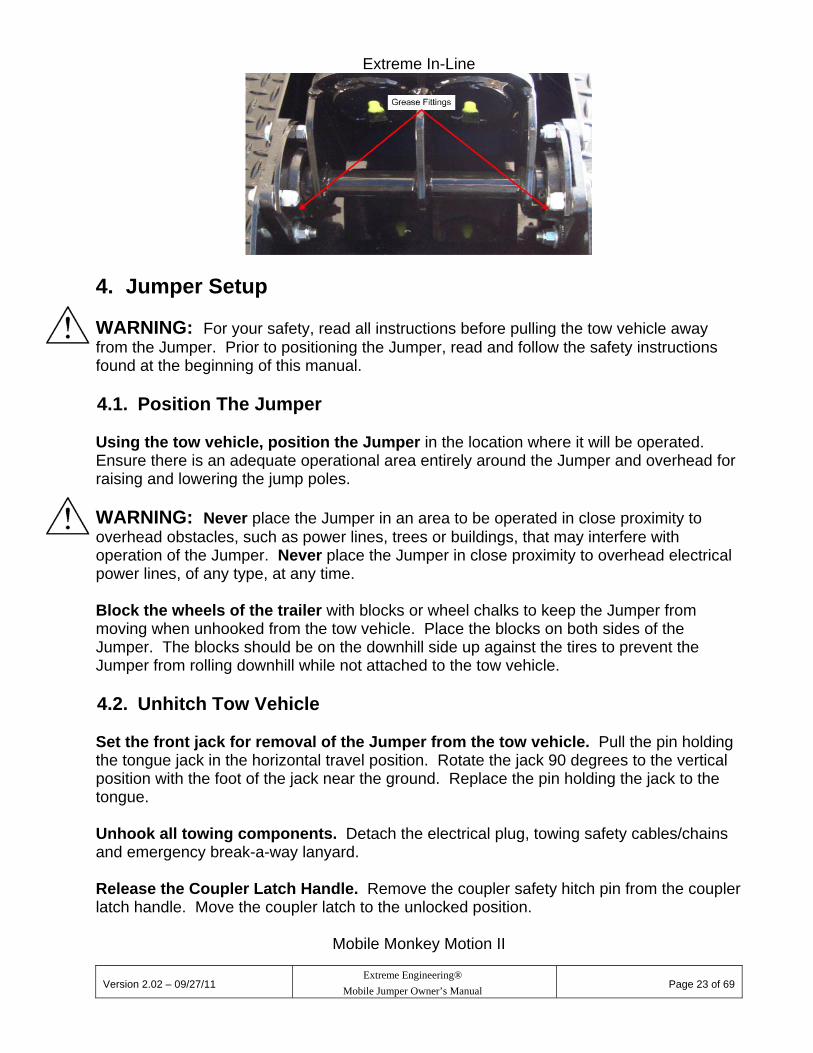
WARNING: Do Not tow or operate the Jumper with loose or missing lift tube hinge mounting hardware, spring pins, set screws or retaining clips. Periodic greasing of Lift Tube and Hydraulic Lift Ram zerk fittings. Mobile Monkey Motion II – Pump grease into each zerk fitting on each aluminum hinge block. There are two hinge blocks per lift tube assembly. Extreme In-line – Pump grease into each zerk fitting on each of the bearings. For both the Mobile Monkey Motion II and the Extreme In-Line, pump grease into each zerk fitting at each end of the hydraulic lift rams where the clevis pins hold the rams to the base and lift tube assembly are located. Apply grease until you can see new grease extruding from the sides of each hinge block and hydraulic lift ram attachment point.
Version 2.02 – 09/27/11
Extreme Engineering®
Mobile Jumper Owner’s Manual
Page 23 of 69
Extreme In-Line
4. Jumper Setup WARNING: For your safety, read all instructions before pulling the tow vehicle away from the Jumper. Prior to positioning the Jumper, read and follow the safety instructions found at the beginning of this manual. 4.1. Position The Jumper Using the tow vehicle, position the Jumper in the location where it will be operated. Ensure there is an adequate operational area entirely around the Jumper and overhead for raising and lowering the jump poles. WARNING: Never place the Jumper in an area to be operated in close proximity to overhead obstacles, such as power lines, trees or buildings, that may interfere with operation of the Jumper. Never place the Jumper in close proximity to overhead electrical power lines, of any type, at any time. Block the wheels of the trailer with blocks or wheel chalks to keep the Jumper from moving when unhooked from the tow vehicle. Place the blocks on both sides of the Jumper. The blocks should be on the downhill side up against the tires to prevent the Jumper from rolling downhill while not attached to the tow vehicle. 4.2. Unhitch Tow Vehicle Set the front jack for removal of the Jumper from the tow vehicle. Pull the pin holding the tongue jack in the horizontal travel position. Rotate the jack 90 degrees to the vertical position with the foot of the jack near the ground. Replace the pin holding the jack to the tongue. Unhook all towing components. Detach the electrical plug, towing safety cables/chains and emergency break-a-way lanyard. Release the Coupler Latch Handle. Remove the coupler safety hitch pin from the coupler latch handle. Move the coupler latch to the unlocked position.
Mobile Monkey Motion II

Version 2.02 – 09/27/11
Extreme Engineering®
Mobile Jumper Owner’s Manual
Page 24 of 69
Extreme In-Line
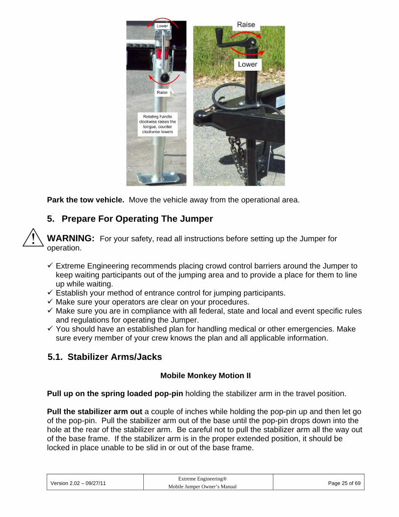
Raise the coupler up off of the tow vehicle hitch ball. Rotate the jack handle clockwise until the coupler is completely up off of the ball. Ensure there is enough clearance between the ball and the bottom of the coupler to allow the tow vehicle to be driven away without catching the coupler.
Monkey Motion II Extreme In-Line
Version 2.02 – 09/27/11
Extreme Engineering®
Mobile Jumper Owner’s Manual
Page 25 of 69
Park the tow vehicle. Move the vehicle away from the operational area. 5. Prepare For Operating The Jumper WARNING: For your safety, read all instructions before setting up the Jumper for operation. Extreme Engineering recommends placing crowd control barriers around the Jumper to
keep waiting participants out of the jumping area and to provide a place for them to line up while waiting.
Establish your method of entrance control for jumping participants. Make sure your operators are clear on your procedures. Make sure you are in compliance with all federal, state and local and event specific rules
and regulations for operating the Jumper. You should have an established plan for handling medical or other emergencies. Make
sure every member of your crew knows the plan and all applicable information. 5.1. Stabilizer Arms/Jacks
Mobile Monkey Motion II Pull up on the spring loaded pop-pin holding the stabilizer arm in the travel position. Pull the stabilizer arm out a couple of inches while holding the pop-pin up and then let go of the pop-pin. Pull the stabilizer arm out of the base until the pop-pin drops down into the hole at the rear of the stabilizer arm. Be careful not to pull the stabilizer arm all the way out of the base frame. If the stabilizer arm is in the proper extended position, it should be locked in place unable to be slid in or out of the base frame.

Version 2.02 – 09/27/11
Extreme Engineering®
Mobile Jumper Owner’s Manual
Page 26 of 69
Place the stabilizer jack on the jack spud of each stabilizer arm. Orient the jack in a vertical position and push the jack mounting pin all the way through the holes of the jack and the stabilizer arm mounting spud. Orient the jack in a vertical position and push the jack mounting pin all the way through the holes of the jack and the mounting spud.
Crank the jack handle clockwise to extend the jacks. Extend the jacks until they contact the ground. If the jacks do not reach the ground before being fully extended, place blocks between the jack foot and the ground to achieve contact with the ground. The jacks will need to be firmly on the ground with a slight upward pressure on the stabilizer arms. Do not attempt to raise the trailer with the stabilizer jacks attached to the stabilizer arms. Damage may occur to the arms if this is done.
Extreme In-Line
Place the stabilizer jacks on the jack spuds located at each of the four jack locations (two on the left side and two on the right side) of the trailer. On the right side of the trailer, two jacks are placed on the jack mount spuds welded to the side of the flatbed of the trailer. Place a jack on the front and rear jack placement positions. Ensure the jack mount pin is inserted fully into the jack mount holds of the jack and trailer.

Version 2.02 – 09/27/11
Extreme Engineering®
Mobile Jumper Owner’s Manual
Page 27 of 69
For the left side of the Extreme In-Line product, there are two different jack mount locations. If your Extreme In-Line product has the pull out stabilizer arms, place the jack on the end of the stabilizer arms. If your Extreme In-Line product DOES NOT have the stabilizer arms, place the jack on the fixed jack mount spud welded to the side of the trailer.
For the stabilizer arm style, pull out on the pop pin to release the stabilizer arm. Extend the arm a short distance and the release the pop pin. Pull the stabilizer arm all the way out until the pop pin slides back in locking the stabilizer arm in place. If the pop pin is engaged properly, you will not be able to pull out or push in the stabilizer arm. Once the arm is extended to the proper position, place a jack on the jack mounting spud at the ends of the stabilizer arms. Ensure the jack mount pin is inserted fully into the jack mount holds of the jack and trailer.

Version 2.02 – 09/27/11
Extreme Engineering®
Mobile Jumper Owner’s Manual
Page 28 of 69
Crank the jack handles clockwise to extend the jacks for both the fixed mount jacks and the stabilizer arm mount jacks.. Extend the jacks until they contact the ground firmly. If the jacks do not reach the ground before being fully extended, place blocks between the jack foot and the ground to achieve contact with the ground. The jacks will need to be firmly on the ground with a slight upward pressure on the stabilizer arms. Do not attempt to raise the trailer with the stabilizer jacks attached to the stabilizer arms. Damage may occur to the arms if this is done. WARNING: Keep hands and feet clear of the stabilizing jack foot while extending the jacks. DO NOT operate the jumper without all jacks in their proper operational positions. 5.2. Jumper Poles Remove the hitch pin from the end of the pole lockdown pin and pull the lockdown pin out from the poles and holding brackets. Remove one pole at a time and place the end without the eye bolt into a lift tube. Repeat this operation for all jump poles. As the poles weigh 75 pounds each, Extreme Engineering recommends using two persons to remove and place the poles into the lift tubes to prevent injury to self or damage to the poles.
Mobile Monkey Motion II
Extreme In-Line

Version 2.02 – 09/27/11
Extreme Engineering®
Mobile Jumper Owner’s Manual
Page 29 of 69
Rotate the jump poles until the eyebolt is perpendicular to the ground.
5.3. Jumper Pole Spreader Bars Place the spreader bar on the black line at the halfway point of the jump poles. This location is 12’ from the tip of the eye bolt at the end of the jump pole. Clamp the spreader bar down onto the jump pole by tightening the thumbscrew. Tighten both sides of the spreader bar.

Version 2.02 – 09/27/11
Extreme Engineering®
Mobile Jumper Owner’s Manual
Page 30 of 69
5.4. Jumper Pole Slings The carabiner with the blue and red swivel attached at one end of each jump sling is attached to the eye bolts located at the ends of the jump poles. The swivels are not to be attached at the jump harness. Make sure the carabiners are securely locked through the eyebolts and swivels.
5.5. Inflatable Jump Pads Extreme engineering recommends placing a protective tarp under the inflatable pads and sleeves to protect them from damage as a result of sharp objects and rough surfaces that may exist where the pads will be used. Protective tarps are not provided by Extreme Engineering. Place a jump pad under the end of the poles at each jump station where the jump slings hang from the jump poles. The positioning of each pad is relative to the red tab sewn onto the side of the pad. The red tab is located at the bottom side of the inflatable pad. Orient the pad such that the red tab is at the bottom. The red tab is also located 4.5’ from one end of the pad, 9.5’ from the opposite end of the pad. Orient the pad to place the 4.5’ end of the pad forward of the pole ends where the jump straps hang, the 9.5’ side is placed rearward of the poles ends.

Version 2.02 – 09/27/11
Extreme Engineering®
Mobile Jumper Owner’s Manual
Page 31 of 69
Any inflatable pad can be used at any jump station. Reference the below diagrams for inflatable pad configuration and parts. Both the Mobile Monkey Motion and Extreme In-Line have a blower sleeve extension for attaching the blower to the first inflatable pad sleeve. The Mobile Monkey Motion II will also have long sleeve extensions to attach the inflatable pads to each other. The Extreme In-Line does not utilize sleeve extensions, the pads are attached to each other utilizing the short sleeves on the pads.

Version 2.02 – 09/27/11
Extreme Engineering®
Mobile Jumper Owner’s Manual
Page 32 of 69
Blower and Blower Sleeve Sleeves Covering Connector

Version 2.02 – 09/27/11
Extreme Engineering®
Mobile Jumper Owner’s Manual
Page 33 of 69
Sleeve Connector (if applicable)
To attach the blower to the first inflatable pad, fully insert the sleeve connector (if applicable) into the short sleeve of the inflatable pad on the outside sleeve. Slide the short blower extension sleeve over the inflatable pad sleeve and the sleeve connector. Wrap the sleeve strap around both the sleeves and the connector at the mid-point of the connector. Tighten sufficiently that the sleeves do not separate during operation. For the Mobile Monkey Motion, attach the inflatable jump pads to each other using the long sleeve extension between each inflatable pad. Slide a sleeve connector inside the short sleeve on the pads until the connector is fully inserted into the short sleeve of the pad. Slide the long inflatable pad sleeve over the inflatable pad short sleeve and the sleeve connector. Wrap a sleeve strap around both the sleeves and the sleeve connector at the mid-point of the connector. Tighten sufficiently that the sleeves do not separate during operation. Repeat this until all three sleeves are connected between the four pads. The short sleeve on the last pad must be left rolled up and a sleeve strap wrapped around the rolled up sleeve to prevent air from escaping that would prevent the pads from inflating fully. For the Extreme In-Line, the inflatable pads are connected to each other with the short sleeves on the pads and sleeve connectors. There is no separate long sleeve between the jump pads. Slide a sleeve connector inside the short sleeve on the pads until the connector is fully inserted into the short sleeve of the pad. Move the next pad to a position next to the first and wrap the short sleeve of the second inflatable jump pad over the outside of the first pad and sleeve connector. Wrap a sleeve strap around both the sleeves and the sleeve connector at the mid-point of the connector. Tighten sufficiently that the sleeves do not separate during operation. Repeat this operation until all remaining jump pads have been connected directly to each other. The short sleeve on the last pad must be left rolled up and a sleeve strap wrapped around the rolled up sleeve to prevent air from escaping that would prevent the pads from fully inflating. The blower must be turned on at all times while operating the jumper. If the blower is turned off, the pads will deflate. Extension Cord Requirements: For the inflatable pad blower, extension cords up to 100’ total in length must be a minimum of 14 gauge between the power source and the inflatable pump. Power cords are not supplied with the products. WARNING: Never turn on the blower prior to turning on power to the hydraulic pump. Always power up the hydraulic pump first and allow the pump to run for one minute before powering up the blower.
Version 2.02 – 09/27/11
Extreme Engineering®
Mobile Jumper Owner’s Manual
Page 34 of 69
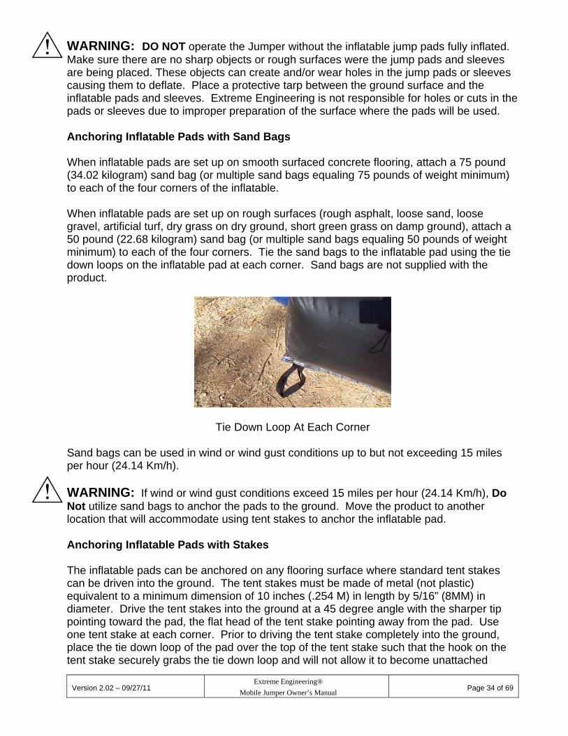
WARNING: DO NOT operate the Jumper without the inflatable jump pads fully inflated. Make sure there are no sharp objects or rough surfaces were the jump pads and sleeves are being placed. These objects can create and/or wear holes in the jump pads or sleeves causing them to deflate. Place a protective tarp between the ground surface and the inflatable pads and sleeves. Extreme Engineering is not responsible for holes or cuts in the pads or sleeves due to improper preparation of the surface where the pads will be used. Anchoring Inflatable Pads with Sand Bags When inflatable pads are set up on smooth surfaced concrete flooring, attach a 75 pound (34.02 kilogram) sand bag (or multiple sand bags equaling 75 pounds of weight minimum) to each of the four corners of the inflatable. When inflatable pads are set up on rough surfaces (rough asphalt, loose sand, loose gravel, artificial turf, dry grass on dry ground, short green grass on damp ground), attach a 50 pound (22.68 kilogram) sand bag (or multiple sand bags equaling 50 pounds of weight minimum) to each of the four corners. Tie the sand bags to the inflatable pad using the tie down loops on the inflatable pad at each corner. Sand bags are not supplied with the product.
Tie Down Loop At Each Corner
Sand bags can be used in wind or wind gust conditions up to but not exceeding 15 miles per hour (24.14 Km/h). WARNING: If wind or wind gust conditions exceed 15 miles per hour (24.14 Km/h), Do Not utilize sand bags to anchor the pads to the ground. Move the product to another location that will accommodate using tent stakes to anchor the inflatable pad. Anchoring Inflatable Pads with Stakes The inflatable pads can be anchored on any flooring surface where standard tent stakes can be driven into the ground. The tent stakes must be made of metal (not plastic) equivalent to a minimum dimension of 10 inches (.254 M) in length by 5/16” (8MM) in diameter. Drive the tent stakes into the ground at a 45 degree angle with the sharper tip pointing toward the pad, the flat head of the tent stake pointing away from the pad. Use one tent stake at each corner. Prior to driving the tent stake completely into the ground, place the tie down loop of the pad over the top of the tent stake such that the hook on the tent stake securely grabs the tie down loop and will not allow it to become unattached

Version 2.02 – 09/27/11
Extreme Engineering®
Mobile Jumper Owner’s Manual
Page 35 of 69
during operation. Drive the tent stake into the ground completely. Stakes are not included with the product.
Tent stakes can be used in wind or wind gust conditions up to but not exceeding 30 miles per hour (48.28 Km/h). WARNING: If wind or wind gust conditions exceed 30 miles per hour (24.14 km/h), Do Not operate the product at all. 5.6. Turn on Lift Pump Power Requirements: To power the hydraulic pump, power must be supplied from a dedicated 20 amp minimum circuit that is not shared with any other electrical device other than the inflatable blower. If using a portable generator to power the pump and blowers, the generator must be a minimum of 6500 watt output for powering both the lift pump and the inflatable pad blower. Extension Cord Requirements: For the hydraulic pump, a single extension cord up to 50 feet in length between the power source and the pump must be a 12 gauge 3-wire minimum. A single extension cord up to 100 feet total in length must be 10 gauge 3-wire minimum. For the inflatable blowers, extension cords up to 100’ total in length must be a minimum of 14 gauge 3-wire between the power source and the inflatable pumps. Plug the extension cord into the power outlet on the pump cover. Ensure that the thermal breaker reset button is all the way in. If an electrical device draws too much current, the thermal breaker will immediately stop all electrical components to prevent component damage. The reset button will pop out of its normal position inside the clear protective cover over the button. Should this happen, there may be a short somewhere in the electrical system or an electrical component has failed causing too much current draw through the system. Pushing the reset button back in will re-enable the electrical system. If the button continually pops out while attempting to operate the product, do not use the product until the cause has been determined and rectified. Contact Extreme Engineering for further help on finding and solving the issue causing the excessive current draw.

Version 2.02 – 09/27/11
Extreme Engineering®
Mobile Jumper Owner’s Manual
Page 36 of 69
Rotate the red power on/off button in the direction of the arrows (clockwise) and allow the switch to pop outward until it stops. Note: The pump will not power on at this point.
Rotate the green power switch on the wireless controller transmitter to the on position. Jump station #3 down button (3DN) or #4 down button (4DN) turns on the hydraulic pump. Press and hold the button down until the pump begins to run. It may take one or two seconds before the pump starts. Reference the below pictures to match your controller style and then use the proper button for pump turnon.
WARNING: Never turn on blowers before turning on power to the hydraulic pump. Always power up the hydraulic pump first and allow the pump to run for one minute minimum before powering up the blowers.

Version 2.02 – 09/27/11
Extreme Engineering®
Mobile Jumper Owner’s Manual
Page 37 of 69
5.7. Flyer Jump Harness
Separate the harness waist belt buckle and place the waist belt around behind the participant.
Quick Release Buckle - Insert the waist belt buckle tab into the slot on the waist belt buckle receiver. Fully insert the buckle until it stops. Pull out on the buckle to ensure the buckle is fully engaged and will not release on its own.

Version 2.02 – 09/27/11
Extreme Engineering®
Mobile Jumper Owner’s Manual
Page 38 of 69
Standard Buckle - Insert the waist belt buckle tab completely through from under the slot on the waist belt buckle receiver. Lay the buckle tab flat on top of the buckle receiver. Pull out on the buckle to ensure the buckle is fully engaged and will not release on its own.
Pull on the end of the waist belt to tighten the jump harness until it is tight around the waist and is above the hips. It may be necessary to grab the waist belt in front of the excess belt holder to properly tighten the waist belt. Do this by moving the belt holder toward the loose end of the waist belt, grab the waist belt between the holder and the buckle and pull to tighten the harness. The excess belt end can then be pulled through the waist belt holder to keep the loose end of the belt out of the jump participants way.

Version 2.02 – 09/27/11
Extreme Engineering®
Mobile Jumper Owner’s Manual
Page 39 of 69
Wrap the leg padding snuggly around the leg. Line up the velcro strips as the first step in adjusting the leg padding. The leg buckle must also be attached. Do Not use the velcro only for the leg padding. See the next step for the leg belt. Insert the leg belt buckle tab into the slot on the leg belt buckle receiver. Fully insert the buckle until it stops. Pull out on the buckle to ensure the buckle is fully engaged and will not release on its own.
Pull on the end of the leg belt to tighten the jump harness until it is tight around the leg padding. It may be necessary to grab the leg belt end in front of the excess belt holder to properly tighten the leg belt. Do this by moving the holder out toward the loose end of the belt, grab the leg belt between the holder and the buckle and pull to tighten the harness. The excess belt end can then be pulled through the excess belt holder to keep the loose end of the belt out of the jump participants way.

Version 2.02 – 09/27/11
Extreme Engineering®
Mobile Jumper Owner’s Manual
Page 40 of 69
The jump harness is now ready to be attached to the jump slings. Attach the jump slings to the harness by placing the carabiner at the end of the jump sling (the end of the sling without the swivel, the swivel goes at the jump pole end) onto one of the three attachment loops. Always select the carabiner loop that is nearest the side of the jump participant. As shown in the following example, the closest loop to the side of the jump participant is the black loop. For the smallest waist size, that fits the jump harness properly, you would use the red loop. For the largest waist size, that fits the jump harness properly, you would use the blue loop.
An additional adjustment can be made to the waist belt padding for the smallest waist size that fits the harness properly. If you are using the red carabiner attachment loop, there is a flap that can be folded inside the waist belt padding to make the padding smaller in size. Take the waist belt padding flap (right side only), fold it over to the inside at the folding line and tuck the flap under the holding loop.

Version 2.02 – 09/27/11
Extreme Engineering®
Mobile Jumper Owner’s Manual
Page 41 of 69
An additional adjustment can be made to the leg padding for the smallest waist size that fits the harness properly. If you are using the red carabiner attachment loop, the end of the leg padding can be folded over to make the padding fit smaller legs. Pull the leg strap and buckle out of the leg strap holder. Fold the leg padding flap outward and tuck completely inside between the leg padding and the leg flap holder.
Version 2.02 – 09/27/11
Extreme Engineering®
Mobile Jumper Owner’s Manual
Page 42 of 69
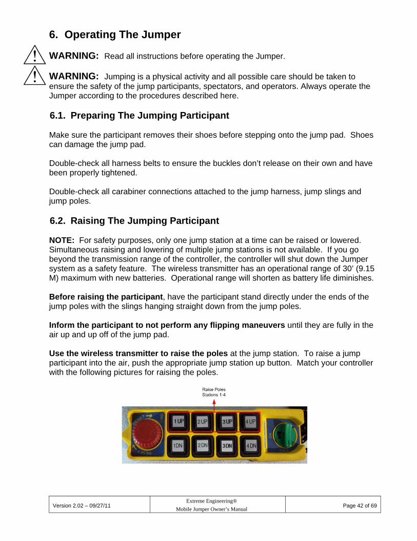
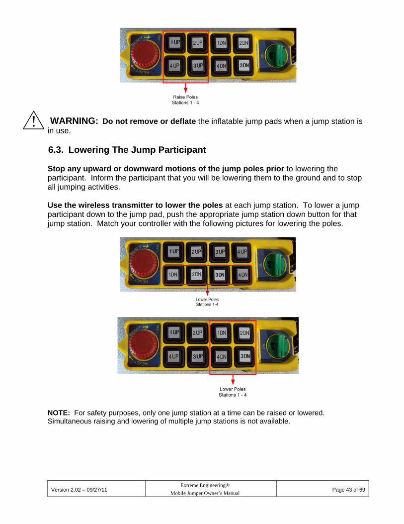
6. Operating The Jumper WARNING: Read all instructions before operating the Jumper. WARNING: Jumping is a physical activity and all possible care should be taken to ensure the safety of the jump participants, spectators, and operators. Always operate the Jumper according to the procedures described here. 6.1. Preparing The Jumping Participant Make sure the participant removes their shoes before stepping onto the jump pad. Shoes can damage the jump pad. Double-check all harness belts to ensure the buckles don’t release on their own and have been properly tightened. Double-check all carabiner connections attached to the jump harness, jump slings and jump poles. 6.2. Raising The Jumping Participant NOTE: For safety purposes, only one jump station at a time can be raised or lowered. Simultaneous raising and lowering of multiple jump stations is not available. If you go beyond the transmission range of the controller, the controller will shut down the Jumper system as a safety feature. The wireless transmitter has an operational range of 30’ (9.15 M) maximum with new batteries. Operational range will shorten as battery life diminishes. Before raising the participant, have the participant stand directly under the ends of the jump poles with the slings hanging straight down from the jump poles. Inform the participant to not perform any flipping maneuvers until they are fully in the air up and up off of the jump pad. Use the wireless transmitter to raise the poles at the jump station. To raise a jump participant into the air, push the appropriate jump station up button. Match your controller with the following pictures for raising the poles.
Version 2.02 – 09/27/11
Extreme Engineering®
Mobile Jumper Owner’s Manual
Page 43 of 69
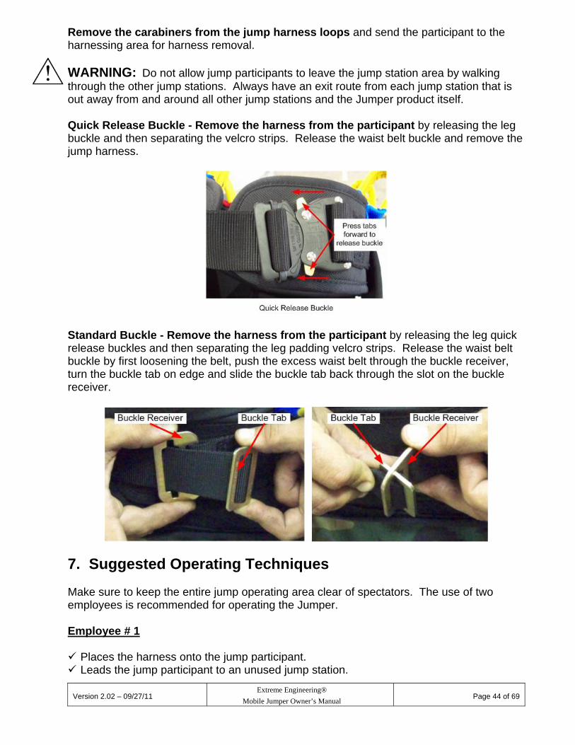
WARNING: Do not remove or deflate the inflatable jump pads when a jump station is in use. 6.3. Lowering The Jump Participant Stop any upward or downward motions of the jump poles prior to lowering the participant. Inform the participant that you will be lowering them to the ground and to stop all jumping activities. Use the wireless transmitter to lower the poles at each jump station. To lower a jump participant down to the jump pad, push the appropriate jump station down button for that jump station. Match your controller with the following pictures for lowering the poles.
NOTE: For safety purposes, only one jump station at a time can be raised or lowered. Simultaneous raising and lowering of multiple jump stations is not available.
Version 2.02 – 09/27/11
Extreme Engineering®
Mobile Jumper Owner’s Manual
Page 44 of 69
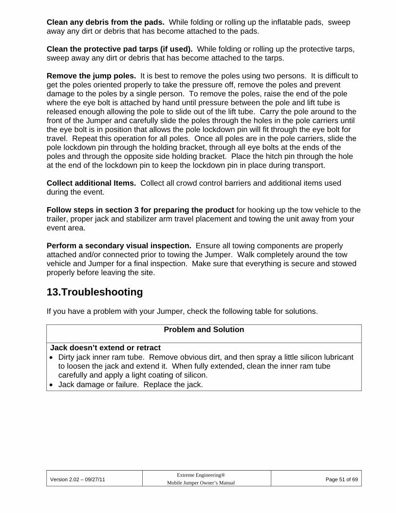
Remove the carabiners from the jump harness loops and send the participant to the harnessing area for harness removal. WARNING: Do not allow jump participants to leave the jump station area by walking through the other jump stations. Always have an exit route from each jump station that is out away from and around all other jump stations and the Jumper product itself. Quick Release Buckle - Remove the harness from the participant by releasing the leg buckle and then separating the velcro strips. Release the waist belt buckle and remove the jump harness.
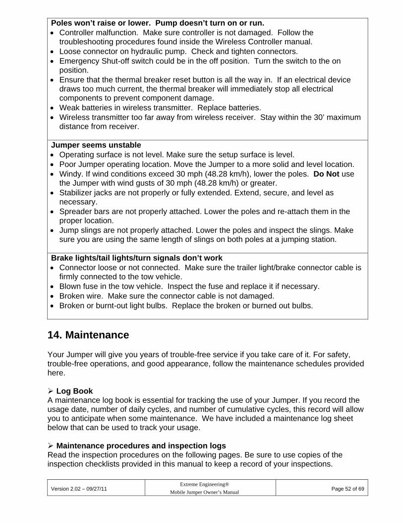
Standard Buckle - Remove the harness from the participant by releasing the leg quick release buckles and then separating the leg padding velcro strips. Release the waist belt buckle by first loosening the belt, push the excess waist belt through the buckle receiver, turn the buckle tab on edge and slide the buckle tab back through the slot on the buckle receiver.
7. Suggested Operating Techniques Make sure to keep the entire jump operating area clear of spectators. The use of two employees is recommended for operating the Jumper. Employee # 1 Places the harness onto the jump participant. Leads the jump participant to an unused jump station.

Version 2.02 – 09/27/11
Extreme Engineering®
Mobile Jumper Owner’s Manual
Page 45 of 69
Attaches the jump slings to the jump harness. Alerts Employee # 2 to begin raising and operating the jump station. Employee # 2
Supervises and advises all jump participants during their jump session. Raises and lowers the participants with the controller transmitter. Unhooks the participants at the end of their jumping session by removing the carabiners
from the jump harness loops. Sends the jump participant back to the harnessing area for removal of the harness. Solves problems, issues and/or concerns during the jumping session. WARNING: When not in use remove the jump slings from the jump poles.
8. Safety rules for the Operators Do Not climb or hang by hands/legs on the jump poles. Always use a jump harness and
jump straps to hang from the jump poles. Do Not stand on top of the Jumper base or trailer. Do Not stand underneath a jumping participant while jumping is in progress. Do Not remove the inflatable pads or turn off the inflatable blower while jumping is in
progress. Do Not leave the Jumper or jumping participants unattended while jumping is in
progress. If you must leave the Jumper unattended when not in use, ensure the jump slings, the
jump poles and the controller transmitter are not accessible by anyone. The best solution is to keep one employee with the Jumper at all times.
Do Not allow a jump participant put on or take off the harness themselves. An employee
must be the only one who attaches or removes the harness for a jump participant. Do Not place any part of your body near or at pinch point locations on the Jumper
during operation. WARNING: Do Not wear loose clothing, such as scarves, neckties, baggy shirts, etc., while operating or inspecting the Jumper to prevent the possibility of becoming entangled in the Jumper’s moving parts. Do Not allow similar lose clothing items to be worn by jump participants during a jump session.
9. Safety Rules For Your Jumping Participants It’s a good idea to make participants aware of some simple rules. We suggest you reproduce the following rules as a poster or handout for the participants and their parents

Version 2.02 – 09/27/11
Extreme Engineering®
Mobile Jumper Owner’s Manual
Page 46 of 69
or guardian to read. The following page can be copied for this purpose. Ready-made signs are also available from Extreme Engineering.
SAFETY RULES
Before You Start
Always follow the instructions given by the operator. After you are placed into the harness, stay in the harnessing area. Wait until the operator leads you to the jump station. Do Not step on the inflatable pad until informed to do so.
During Your Jump Session
Stay above the inflatable pad when jumping. Always aim for the pad when descending downward toward the pad.
Do Not grab and pull on the poles with your hands. Use only the jump straps to assist your jumping. Do Not jump without the jump slings attached to the jump harness. Do Not begin your jumping until you are raised up in the air. Do Not walk under jump poles.
Ending Your Session
Stop performing extreme movements, such as flips, when notified by the operator to stop jumping.
When you are lowered down onto the pad, remain relaxed and land with your feet
first on the pad. Do Not attempt to remove the harness or jump straps. An operator will remove
these from you at the appropriate time after your jumping session has ended. Once the jump slings are removed from the harness and you are informed by the
operator it is OK, go to the harnessing area for removal of the harness. Allow the operator to remove the harness from you.

Version 2.02 – 09/27/11
Extreme Engineering®
Mobile Jumper Owner’s Manual
Page 47 of 69
10. Special Jumping Participant Situations The vast majority of jumping takes place without any difficulty or interruption but sometimes a problem can occur. Here’s what to do: 10.1. Participant Becomes Frozen During Jumping Session Ask the participant to remain calm. Inform the participant that you are going to lower them slowly and safely back down to the inflatable pad. Once the participant is back on the inflatable pad, remove the jump straps from the jump harness and send the participant to the harnessing area for removal of the harness. NOTE: Encouraging the participant to keep jumping typically does not solve a frozen jumper situation. 10.2. Participant Reports Discomfort With Harness Ask the participant to remain calm. Inform the participant that you are going to lower them slowly and safely back down to the inflatable pad. If the discomfort is caused by the harness, adjust the harness, and let the participant resume their jump session again. If the participant continues to report discomfort and is unable to resume for whatever reason, remove the jump straps from the jump harness and send the participant to the harnessing area for removal of the harness. 10.3. Participant Is Intentionally Reckless Ask the participant to take it easy. Choose one of the following options if they continue to be reckless: 1. If you do not believe the adjacent jumping participants are endangered:
Inform the reckless participant to calm down and lower them down to the pad. Unhook the participant’s jump slings and send them to the harness area for harness
removal. 2. If you believe adjacent participants might be endangered:
Inform the reckless participant to stop jumping. Inform the adjacent participants to stop jumping. Lower the adjacent participants down to the pad and have them wait to resume their
jumping session. Inform the reckless participant that they will be lowered to the pad. Lower the
reckless participant down to the pad. Unhook the reckless participant’s jump slings from the harness and send them to the
harness area for harness removal.

Version 2.02 – 09/27/11
Extreme Engineering®
Mobile Jumper Owner’s Manual
Page 48 of 69
The adjacent participants may now be allowed to resume their jumping session.
10.4. Participant Is Too Light To Achieve Jumping Motion Ask the participant to stay calm and inform them you will be lowering them down to the pad. Lower the participant down to the pad. Remove the jump straps from the jump harness and send the participant to the harness removal area.
11. Additional Jumper Situations 11.1. Forgot To Attach Jumper Pole Slings to Jumper Poles Ask the jump participant (if applicable) to stand next to the jump pad. Lower the poles if necessary. Attach the jump slings to the jump poles with the carabiner and swivel end of the sling. 11.2. Hydraulic Lift Stops Operating With Participant Suspended In Air You can manually lower the poles without the pump running or electrical power. Each jump station has its own valve. Use a small pointed tool that will reach the center of the valve to be manually actuated. The tool needs to be small enough in diameter to fit down through the hole at the center and long enough allow you to depress the valve until the poles begin to lower. Continue to hold down on the valve until the poles lower to the desired height and the release the valve. Once the poles are low enough, unhook the jump participant from the jump slings safely.

Version 2.02 – 09/27/11
Extreme Engineering®
Mobile Jumper Owner’s Manual
Page 49 of 69
Mobile Monkey Motion II
Extreme In-Line
WARNING: Do Not operate a jump station that does not raise or lower with the controller. The issue must be corrected prior to using the jump station again.

Version 2.02 – 09/27/11
Extreme Engineering®
Mobile Jumper Owner’s Manual
Page 50 of 69
11.3. Emergency Shut Off Use the emergency on/off power switches to disable all electrical power to the pump and wireless controller. Depress the red stop button. Follow the instructions in the previous section to lower any jump participants that are suspended in the air after pushing the emergency stop button. Stop all operations of the Jumper until the situation requiring the emergency shutdown has been corrected and the Jumper operates properly.
12. End Of Event Takedown WARNING: For your safety, read all instructions before takedown of the Jumper. WARNING: Keep the area clear of people, cars, etc., during all steps of the takedown. Jump Harnesses. Collect all jump harnesses from participants. Remove Jump Straps. Remove the jump straps from the jump poles by removing the carabiner that attaches the straps to the jump pole eye bolts. Lower poles. Press the down button on the controller for all jump stations to completely lower the poles. Turn off lift pump. Depress the emergency on/off switch to turn off all electrical power to the jumper. Remove the power extension cord. Turn off inflatable blowers. Turn off the power switch on the blowers. Unplug the extension cords from the blowers and from the power outlets. Remove blower. Remove the blower from the primary pad by loosening the strap and carefully pull the sleeve off of the pump connection. Separate the pads. Separate the pad sleeves, the sleeve extensions (if applicable) and sleeve connectors. This is accomplished by loosening the straps on the sleeves and carefully pull the sleeves off of the connectors.
Version 2.02 – 09/27/11
Extreme Engineering®
Mobile Jumper Owner’s Manual
Page 51 of 69
Clean any debris from the pads. While folding or rolling up the inflatable pads, sweep away any dirt or debris that has become attached to the pads. Clean the protective pad tarps (if used). While folding or rolling up the protective tarps, sweep away any dirt or debris that has become attached to the tarps. Remove the jump poles. It is best to remove the poles using two persons. It is difficult to get the poles oriented properly to take the pressure off, remove the poles and prevent damage to the poles by a single person. To remove the poles, raise the end of the pole where the eye bolt is attached by hand until pressure between the pole and lift tube is released enough allowing the pole to slide out of the lift tube. Carry the pole around to the front of the Jumper and carefully slide the poles through the holes in the pole carriers until the eye bolt is in position that allows the pole lockdown pin will fit through the eye bolt for travel. Repeat this operation for all poles. Once all poles are in the pole carriers, slide the pole lockdown pin through the holding bracket, through all eye bolts at the ends of the poles and through the opposite side holding bracket. Place the hitch pin through the hole at the end of the lockdown pin to keep the lockdown pin in place during transport. Collect additional Items. Collect all crowd control barriers and additional items used during the event. Follow steps in section 3 for preparing the product for hooking up the tow vehicle to the trailer, proper jack and stabilizer arm travel placement and towing the unit away from your event area. Perform a secondary visual inspection. Ensure all towing components are properly attached and/or connected prior to towing the Jumper. Walk completely around the tow vehicle and Jumper for a final inspection. Make sure that everything is secure and stowed properly before leaving the site.
13. Troubleshooting If you have a problem with your Jumper, check the following table for solutions.
Problem and Solution
Jack doesn’t extend or retract Dirty jack inner ram tube. Remove obvious dirt, and then spray a little silicon lubricant
to loosen the jack and extend it. When fully extended, clean the inner ram tube carefully and apply a light coating of silicon.
Jack damage or failure. Replace the jack.
Version 2.02 – 09/27/11
Extreme Engineering®
Mobile Jumper Owner’s Manual
Page 52 of 69
Poles won’t raise or lower. Pump doesn’t turn on or run. Controller malfunction. Make sure controller is not damaged. Follow the
troubleshooting procedures found inside the Wireless Controller manual. Loose connector on hydraulic pump. Check and tighten connectors. Emergency Shut-off switch could be in the off position. Turn the switch to the on
position. Ensure that the thermal breaker reset button is all the way in. If an electrical device
draws too much current, the thermal breaker will immediately stop all electrical components to prevent component damage.
Weak batteries in wireless transmitter. Replace batteries. Wireless transmitter too far away from wireless receiver. Stay within the 30’ maximum
distance from receiver. Jumper seems unstable Operating surface is not level. Make sure the setup surface is level. Poor Jumper operating location. Move the Jumper to a more solid and level location. Windy. If wind conditions exceed 30 mph (48.28 km/h), lower the poles. Do Not use
the Jumper with wind gusts of 30 mph (48.28 km/h) or greater. Stabilizer jacks are not properly or fully extended. Extend, secure, and level as
necessary. Spreader bars are not properly attached. Lower the poles and re-attach them in the
proper location. Jump slings are not properly attached. Lower the poles and inspect the slings. Make
sure you are using the same length of slings on both poles at a jumping station.
Brake lights/tail lights/turn signals don’t work Connector loose or not connected. Make sure the trailer light/brake connector cable is
firmly connected to the tow vehicle. Blown fuse in the tow vehicle. Inspect the fuse and replace it if necessary. Broken wire. Make sure the connector cable is not damaged. Broken or burnt-out light bulbs. Replace the broken or burned out bulbs.
14. Maintenance Your Jumper will give you years of trouble-free service if you take care of it. For safety, trouble-free operations, and good appearance, follow the maintenance schedules provided here. Log Book A maintenance log book is essential for tracking the use of your Jumper. If you record the usage date, number of daily cycles, and number of cumulative cycles, this record will allow you to anticipate when some maintenance. We have included a maintenance log sheet below that can be used to track your usage. Maintenance procedures and inspection logs Read the inspection procedures on the following pages. Be sure to use copies of the inspection checklists provided in this manual to keep a record of your inspections.

Version 2.02 – 09/27/11
Extreme Engineering®
Mobile Jumper Owner’s Manual
Page 53 of 69
Detailed description of inspection items Inspect the Jumper thoroughly before you take it out to an event. Your safety on the road, during setup/operation and your customers’ safety depend on it.
Hydraulic Hose Make sure the hoses are not leaking. It you find a leak, call Customer Service for assistance. Pole lift system Raise and lower the jump poles. Make sure the poles lift smoothly and completely. If the poles don’t raise or lower completely, or there are any hesitations in its motion, contact Extreme Engineering for help. Check that all wiring connection are properly attached.
Loose or broken parts Inspect the entire Jumper for loose or broken parts. Replace broken parts and tighten loose parts.
Jacks Extend each jack out completely to clean the inner jack tube. Coat the tube with silicon spray lubricant after cleaning. Trailer Hitch, Tow Ball and Safety Cables Make sure the trailer hitch is of the proper weight capacity and the towing ball is a 2-5/16” diameter. Inspect the safety cable and mounting hardware for wear, if at all questionable, replace it.
WARNING: If you have any doubt about the hitch or the safety cable, consult with your local trailer hitch supply shop. This is critical for safe transport. A trailer becoming unhitched during transport can be a catastrophic. Trailer towing coupler Make sure the bolts holding the coupler to the trailer are tight and torqued to the proper specification for the Grade 8 bolts.
Trailer wheels Make sure the lug nuts are tight and torqued to 90 foot pounds. Lug nuts should be checked every 100 miles.
Trailer lights Connect the trailer light and brake connector to the tow vehicle. Be sure the taillights, brake lights, running lights and turn signals are performing correctly. Replace any broken or burnt-out bulbs. Keep spare bulbs on hand. When troubleshooting non working lights, remember to check the tow vehicle’s fuses also and replace as necessary. Check for broken light lenses and replace if necessary.
Loose or broken parts Inspect the entire Jumper for loose or broken parts. Replace broken parts (call Customer Service to order) and tighten loose parts.

Version 2.02 – 09/27/11
Extreme Engineering®
Mobile Jumper Owner’s Manual
Page 54 of 69
Hitch pins Hitch pins are an additional safety measure for their intended use. Keep spares on hand. Only replace with equal quality. WARNING: For both use and transport, never modify, alter, or adapt your equipment with anything other than the correct keeper pins or safety snap pins! Doing so could create a serious hazard! Harnesses Protect your harnesses from constant direct sunlight, heat and nylon-damaging substances such as acids, alkalis, oxidizing agents, and bleach.
Carabiners Make sure the carabiners lock properly. All surfaces of the carabineers should be free of cracks, sharp edges, corrosion, burrs, or excessive wear. Be sure the gate and any locking mechanism closes freely and completely. Gate opening and closing should be quick and easy. If washing and drying does not remedy a gummed-up carabiner, replace it. Replace carabiners if they are worn or damaged. WARNING: If a carabiner does not pass inspection (even after cleaning), destroy and replace it with a new one. This is absolutely critical for safe operation. Always keep a spare carabiner on hand.
15. Cleaning And Other Special Care Jumper Clean the Jumper as you would a boat, camper or recreational vehicle. Hose it off. Use a solution of warm soapy water to remove dirt from the Jumper.
Carabiners Keep carabiners dry and clean. Protect them from corrosion. Do Not store them in very humid or salty air, with damp equipment or clothing, or near corrosive chemicals. Do Not file carabineers for any reason. If notches appear, replace the carabineer. If a carabiner gate sticks, wash it in warm soapy water, rinse thoroughly and lubricate with either dry graphite or light lubricant (such as WD-40) at the hinge areas and locking mechanism.
Harnesses Hand-wash a dirty harness in cool water with a mild soap. Allow it to dry in a shaded area.
15.1. Protection From The Elements Store the Jumper as you would a boat, camper or recreational vehicle. Storing the Jumper in a covered shelter or garage will keep it cleaner and preserve its appearance longer. Storing the Jumper outdoors is no problem. However, you may want to place a tarp over it to preserve the finish from excessive exposure to the elements. To prevent damage, the tarp needs to allow air circulation. Trapping moisture under a polypropylene tarp can lead to rust or corrosion damage of components. Do Not store harnesses for extended periods in direct sunlight
Version 2.02 – 09/27/11
Extreme Engineering®
Mobile Jumper Owner’s Manual
Page 55 of 69
16. Quick Checklists And Log On the next pages you will find condensed maintenance checklists, plus a maintenance log sheet, which you can photocopy and use. If you find any of the conditions discussed in the below inspection items and/or inspection checklist, you must replace the part. If you are unsure whether or not the part requires replacement, contact Extreme Engineering for further inspection assistance.
16.1. Per-Use Maintenance Jump slings – Check webbing for fraying or broken strands. Check for kinks, wear or damage to the webbing. Jump poles – Check for cracks, chipping and/or fractures. Hydraulic hoses – Check for leaks at lift ram and pump connections and the hose. Trailer lights – Tail, brake, running, turn signal lights should be working. Trailer tires – Pressure at 50 psi or to manufacturer’s specifications. Tread must be adequate, with no objects in treads. Harnesses – Must be in good condition, not worn. When dirty, hand wash in cool water, and dry in a shaded area (not in direct sunlight). Carabiners – Check for bent, loose, or missing rivets. The gate/lock must close freely. If gummed up, clean with soapy water and dry. Periodic lubricating with only a few drops of light oil or graphite powder at the hinge points will free sticky mechanisms. If the hinge points or movement points do not operate freely even after light lubrication, replace the carabiners. 16.2. Periodic Maintenance Loose or broken parts. Replace broken parts; tighten loose parts. Trailer hitch. Be sure the hitch, hitch lock, and light/brake cable all are operating correctly. Be sure the safety cable is OK. Trailer coupler. Make sure the bolts are tight. Trailer wheels. Make sure lug nuts are tight. Trailer electric brakes. Check for correct operation of the brakes and breakaway switch. Jacks. Extend all jacks and clean inner ram tubes. Coat with silicon spray lubricant. Jump lift system. Be sure the jump poles lift smoothly. Check that connectors on the hydraulic lift pump are tight (control cable, power, and ground). Tighten if needed.
Version 2.02 – 09/27/11
Extreme Engineering®
Mobile Jumper Owner’s Manual
Page 56 of 69
Battery. Check terminals for corrosion; clean if needed. Clean the Jumper. Wash with soap and water. Pole lift system. Be sure the poles raise and lower smoothly. Grease the zerk fittings on the aluminum hinge blocks. Check that connectors on the hydraulic lift pump are tight (control cable, power, and ground). Tighten if needed. Jump Slings. Check webbing for fraying or broken strands. Check for kinks, wear or damage to the webbing. REPLACE IF ANY SIGNS OF WEAR. Jump poles. Check for cracking, chipping and/or fractures. If you purchased you poles prior to January 2011, your poles must be replaced 12 months after the purchase. If you purchased your poles in 2011, these poles must be replaced 24 months after purchase. If your poles have been damaged (cracking, chipping, fracturing, splintering) you must replace your poles immediately. Replace your poles only with Extreme Engineering manufactured poles. Poles purchased from 2011 to current must now be replaced every 2 years (24 calendar months) from the date of purchase. WARNING: Always replace any suspect jump pole. This is absolutely critical for safe operation. If you suspect a pole is damaged and are not sure, call Extreme Engineering for assistance before operating the Jumper. Clean the Jumper. Wash with warm soapy water just as you would r spray at a car wash, like a boat or camper. Be careful not to use a high-pressure hose on any wiring or electronics.

Version 2.02 – 09/27/11
Extreme Engineering®
Mobile Jumper Owner’s Manual
Page 57 of 69
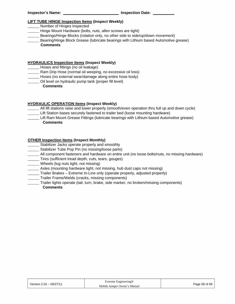
17. Inspection/Maintenance Checklists
Inspection Checklist Inspector’s Name: __________________________ Inspection Date: __________ HARNESS Inspection Items (Inspect Daily) _____ Number of Harnesses Inspected _____ Leg Belt Webbing (fraying, tearing, cuts) _____ Waist Belt Webbing (fraying, tearing, cuts) _____ Sewn Seams / Overlaps / Belt Ends (sewn thread not separating) _____ Buckles (insertion, release, wear) _____ Carabiner Attachment Loops (fraying, tearing, cuts) Comments CARABINER Inspection Items (Inspect Daily) _____ Number of Carabiners Inspected _____ Body Condition (wear, grooves, damage) _____ Gate opens and closes completely without help _____ Gate Hinge pin (intact)
Comments SWIVEL Inspection Items (Inspect Daily) _____ Number of Swivels Inspected _____ Body Condition (wear, grooves, damage) _____ Rotation (smooth, body halves tight no play)
Comments SLING STRAP Inspection Items (Inspect Daily) _____ Number of Slings Inspected _____ Strap Condition (fraying, tearing, cuts) _____ End Loops (sewing thread not separating, fraying, tearing, cuts) _____ Gate Hinge pin
Comments POLE Inspection Items (Inspect Daily) _____ Number of Poles Inspected _____ Fiberglass Pole Condition (gouges, splintering, damage) _____ Pole Eye Bolt (wear, grooves, damage, loose) _____ Eye Bolt Caps (loose)
Comments LIFT TUBE HINGE Inspection Items (Inspect Daily) _____ Number of Hinges Inspected _____ All Hinge parts are solidly mounted (loose hardware / bearings / hinge rod)
Comments
Version 2.02 – 09/27/11
Extreme Engineering®
Mobile Jumper Owner’s Manual
Page 58 of 69
Inspector’s Name: __________________________ Inspection Date: __________ LIFT TUBE HINGE Inspection Items (Inspect Weekly) _____ Number of Hinges Inspected _____ Hinge Mount Hardware (bolts, nuts, allen screws are tight) _____ Bearings/Hinge Blocks (rotation only, no other side to side/up/down movement) _____ Bearing/Hinge Block Grease (lubricate bearings with Lithium based Automotive grease)
Comments HYDRAULICS Inspection Items (Inspect Weekly) _____ Hoses and fittings (no oil leakage) _____ Ram Drip Hose (normal oil weeping, no excessive oil loss) _____ Hoses (no external wear/damage along entire hose body) _____ Oil level on hydraulic pump tank (proper fill level)
Comments HYDRAULIC OPERATION Items (Inspect Weekly) _____ All lift stations raise and lower properly (smooth/even operation thru full up and down cycle) _____ Lift Station bases securely fastened to trailer bed (loose mounting hardware) _____ Lift Ram Mount Grease Fittings (lubricate bearings with Lithium based Automotive grease)
Comments OTHER Inspection Items (Inspect Monthly) _____ Stabilizer Jacks operate properly and smoothly _____ Stabilizer Tube Pop Pin (no missing/loose parts) _____ All component fasteners and hardware on entire unit (no loose bolts/nuts, no missing hardware) _____ Tires (sufficient tread depth, cuts, tears, gouges) _____ Wheels (lug nuts tight, not missing) _____ Axles (mounting hardware tight, not missing, hub dust caps not missing) _____ Trailer Brakes – Extreme In-Line only (operate properly, adjusted properly) _____ Trailer Frame/Welds (cracks, missing components) _____ Trailer lights operate (tail, turn, brake, side marker, no broken/missing components)
Comments

Version 2.02 – 09/27/11
Extreme Engineering®
Mobile Jumper Owner’s Manual
Page 59 of 69
Maintenance Checklist
Inspector’s Name: __________________________ Inspection Date: __________ Towing Components (Monthly) _____ Lubricate towing coupler latch handle with lightweight oil. _____ Verify coupler to tongue bolts tightened to 220 ft-lbs (30.42 Kg-m) _____ Verify tongue to tower frame bolts tightened to 110 ft-lbs (21 Kg-m) _____ Verify wheel lug nuts tightened to 90 ft-lbs (12.45 Kg-m ) _____ Verify emergency brake battery tests properly, replace when battery won’t hold charge. Comments Towing Components (Annually, earlier if necessary depending on usage) _____ Adjust brakes (Extreme In-Line only). _____ Repack wheel bearings. Comments Lift Tube Bearings – Extreme In-Line Only (Semi-annually) _____ With hand grease gun apply grease through the zerk fitting on each bearing until grease is seen exiting the sides of the bearing (2 bearings per jump station). Comments Lift Tube Hinge Blocks – Monkey Motion II Only (Monthly) _____ With hand grease gun apply grease through the zerk fitting into each hinge block (2 per jump station) until grease is seen exiting the sides of the hinge blocks. Comments Lift Tube Hydraulic Rams (Monthly) _____ With hand grease gun apply grease into each zerk fitting at each end of the hydraulic rams until grease is seen exiting where the clevis pin attaches the rams. Comments

Version 2.02 – 09/27/11
Extreme Engineering®
Mobile Jumper Owner’s Manual
Page 60 of 69
17.1. Maintenance Log Use this log to keep a record of maintenance activity not covered by the inspection checklists. This might include parts replacement, calls to Extreme Engineering, etc.
Date Description

Version 2.02 – 09/27/11
Extreme Engineering®
Mobile Jumper Owner’s Manual
Page 61 of 69
18. Safe Towing Tips We encourage you to be a safe, courteous driver when towing your Jumper. Keep the following in mind when towing your Jumper. Be sure that the lug nuts are tightened.
Be sure to use the safety cable at all times.
Be sure the tail lights, brake lights, and turn signals are functioning correctly.
Be sure the trailer’s brakes are working correctly.
Be sure your trailer is properly registered with your state motor vehicle department.
Always observe the posted speed limits for trailers when towing your Jumper. Be
especially cautious (and reduce your speed) when encountering windy, snowy, or rainy conditions.
Install extended side rear view mirrors on your towing vehicle. Your Jumper is over 24
feet in length and you’ll need the mirrors to see traffic directly behind you.
Signal before changing lanes. When you change lanes, be aware of traffic behind you and at your sides. Allow plenty of clearance before changing lanes.
Do Not attempt to make tight left or right turns.

Version 2.02 – 09/27/11
Extreme Engineering®
Mobile Jumper Owner’s Manual
Page 62 of 69
19. Specifications 19.1. Mobile Monkey Motion II Jumper Specifications
Operational Footprint 50’ wide x 50’ long x 26’ high (15.24 M x 15.24 M x 7.93 M) Set up for operating with jump pads inflated.
Operating Temperature 20 Degrees Fahrenheit (-6.6 Celsius) Minimum Overall Length 27’ (8.32 M) Travel Mode with Jumper Poles Trailer Length 25’ 4” (7.72 M) without Jumper Poles Overall Width 7’ (2.14 M) Travel Mode Unladen Weight 2000 Lbs (907.19 Kg) with Jumper Poles Maximum Gross Vehicle Weight
3500 Lbs (1587.56 Kgs)
Jumper Pole Maximum Height Raised
24’ ( 7.325 M)
Jump Pole Length 24’ 4” (7.39 M) Unladen Tongue Weight 250 Lbs (113.4 Kg) Trailer Type Single Axle with Fenders Axle 3,500 Lbs (1587.56 Kgs) maximum load
4" Drop Idler Heavy duty tapered roller bearings 4–leaf Springs
Brakes None Hitch Requirements Class 3 – 5000 Lbs (2268.0 Kgs) minimum capacity Coupler Specifications 12,000 Lbs (5443.1 Kgs) rated
Type – Formed bolt-on Ball Diameter – 2-5/16” (58.75 Mm) Grade 8 Bolt Torque – 150 Ft-lbs (20.74 Kg-m)
Wheel Specifications 15”(381 Mm) diameter 4-1/2” (114.3 Mm) bolt pattern
Tire Specifications ST205 / 75 D15 Carlisle, trailer rated (may change without notice) Load Range C Maximum Load 1820 Lbs (825 Kgs) at 50 PSI (345 kPa) Cold
Tire pressure 50 psi (345 kPa) Cold Wiring Standard 4-Way towing plug
12 Volt DC

Version 2.02 – 09/27/11
Extreme Engineering®
Mobile Jumper Owner’s Manual
Page 63 of 69
19.2. Extreme In-Line Jumper Specifications
19.3. Steel Framing And Weld Specifications
Operational Footprint 35’ wide x 45’ long x 26’ high (10.67 M x 13.72 M x 7.935 M) Set up for operating with jump pads inflated.
Operating Temperature 20 Degrees Fahrenheit (-6.6 Celsius) Minimum Overall Length 27’ (8.32 M) Travel Mode with Jumper Poles Trailer Length 27’ 10” (8.49 M) Overall Width 8’ 2” (2.49 M) Travel Mode Total Weight 4400 Lbs (1995.81Kg) with Jumper Poles, pads, blower Maximum Gross Vehicle Weight
7000 Lbs (3175.15Kgs)
Jumper Pole Maximum Height Raised
24’ ( 7.315 M)
Jump Pole Length 24’ 4” (7.39 M) Tongue Weight 250 Lbs (113.4 Kg) Trailer Type Flatbed Axles 3,500 Lbs (1587.57Kgs) maximum load per axle
One front idler axle and one rear brake axle Heavy duty tapered roller bearings 4–leaf springs
Brakes Electric brakes, rear trailing axle only Hitch Requirements Class 3 or 4 – 7000 Lbs (3175.15 Kgs) minimum capacity Coupler Specifications 12,000 Lbs (5443.1 Kgs) rated
Type – Formed bolt-on Ball Diameter – 2-5/16” (58.75 Mm) Grade 8 Bolt Torque – 150 Ft-lbs (20.74 Kg-m)
Wheel Specifications 15”(381 Mm) diameter 4-1/2” (114.3 Mm) bolt pattern
Tire Specifications ST205 / 75 D15 Carlisle, trailer rated (may change without notice) Load Range C Maximum Load 1820 Lbs (825 Kgs) at 50 PSI (345 kPa) Cold
Tire pressure 50 psi (345 kPa) Cold Wiring Standard 7-Way recreational vehicle towing plug
12 Volt DC
Steel Framing Tubing is ASTM A500 Flat plate is ASTM A572
Welds Welding is American Welding Society and A15C

Version 2.02 – 09/27/11
Extreme Engineering®
Mobile Jumper Owner’s Manual
Page 64 of 69
19.4. Hydraulic Lift Pump Specifications
Pump 110 Volt Single Action Hydraulic (powered up only, gravity down)Dexron III Automatic Transmission oil
Power Cord 12 gauge 3 wire 50’ (15.24 M) maximum, single cord 10 gauge 3 wire 100’ (30.48 M) maximum, single cord
Electrical Power 20 amp recommended (15 amp minimum), not shared with any other electrical device.
Generator Power 3500 watts minimum, not shared with any other electrical device 19.5. Inflatable Blower Specifications
Power Cord 14 gauge 3 wire 100’ (30.48 M) maximum Electrical Power 15 amp Minimum CFM 1000 Cubic Feet per Minute Generator Power 1 @ 1.0 horsepower – 1500 watts
19.6. Portable Generator Specifications
Electrical Power Minimum 6500 watt output for operating the hydraulic pump and inflatable blower.
19.7. Jump Participant Limits
Minimum Weight Jump participants must weigh at least 45 pounds (20.412 Kg)Maximum Weight Jump participants must NOT weigh more than 250 pounds
(113.398 Kg). Minimum Age Jump participants must be at least 4 years of age. Maximum Participants Four jump participants total, one jump participant per jump
station. 19.8. Operational Limits
Maximum Wind Speed 30 mph (48.28 km/h) Maximum Wind Speed Inflatable Jump Pad
Smooth Surfaces – 15 mph (24.14 km/h). Rough Surfaces – 30 mpg (48.28 km/h).
Operating Surface Level
Surfaces must be level. Do not operate on surface grades of more than 1%.
19.9. Jump Pad Tethering
Smooth Surfaces 75 lb (34.02 kg) weight tied too each corner of pad. Rough Surfaces 50 lb (22.68 kg) weight tied to each corner of pad. Tent Stakes Minimum Length Minimum Diameter
Where useable, drive a tent stake fully into the ground at each corner of pad and tie pad to tent stakes. 10 inches (25.4 cm). 5/16 inch (.8 cm).
Version 2.02 – 09/27/11
Extreme Engineering®
Mobile Jumper Owner’s Manual
Page 65 of 69
20. Limited Warranty EXTREME ENGINEERING warrants to the first consumer purchaser that this product will be free from defective workmanship and materials. This warranty is nontransferable. Warranty is subject to the following conditions: 1. Extreme Engineering agrees that it will, at its option, either repair or replace a defective
part or will, at its option, repair or replace the defective product, at no charge to the purchaser for labor for a period of ninety (90) days, at factory, from date of delivery, and at no charge to the purchaser for parts for a period of one (1) year from date of delivery (shipping and handling costs will apply). The consumer purchaser will have the following options when exchanging warranted parts: 1. The consumer purchaser will have to send the defective part or product back to Extreme Engineering’s manufacturing plant. The defective part or product will be determined by Extreme Engineering if it is defective. Extreme Engineering will send a replacement part free of charge if the part or product is found defective. or 2. The consumer purchaser will initially be charged for the warranted part or product. Once Extreme Engineering receives the defective part or product the consumer purchaser will be credited back if the part or product is found to be defective. Consumables are covered for 30 days (harnesses, inflatable jumper pads, slings, carabiners, poles etc.). You may contact Extreme Engineering for additional details on consumable items. We have a 90-day warranty on electronics, 30-days on labor, 90-day on parts.
2. This limited warranty is valid only when the product is installed, operated and
maintained in accordance with the Extreme Engineering Owner’s Manual. Any deviation from these recommended procedures must be approved in writing by Extreme Engineering.
3. This limited warranty does not apply to any part which has been subjected to misuse,
abnormal service or handling or which has been altered or modified in design or construction.
4. This limited warranty does not apply to changes in the exterior appearance of the
mobile Extreme Air In Line and/or Monkey Motion Jumper system™. Custom painted products are not covered by Extreme Engineering’s limited warranty.
4. Neither the sales personnel of the seller nor any other person is authorized to make
any warranties other than those described herein or to extend the duration of any warranties beyond the time period described, on behalf of Extreme Engineering.
5. Do Not book events until arrival of Extreme Engineering equipment. Extreme
Engineering is not responsible for lost revenue from events booked prior to final delivery of equipment. Extreme Engineering is also not responsible for lost revenue due to unforeseen delays in shipment or delivery of Extreme Engineering equipment.
6. Customer agrees to use OEM parts when servicing an Extreme Engineering product.
If Customer fails to abide by this term the product warranty will void and Extreme Engineering will not be responsible for failure of proper operation of an Extreme Engineering product.

Version 2.02 – 09/27/11
Extreme Engineering®
Mobile Jumper Owner’s Manual
Page 66 of 69
7. By operating this product, customer promises to operate and use any equipment in
accordance with all owner’s manuals service recommendations, service bulletins, recommendations and safety tips which Customer has received or may receive in the future in accordance with sound and accepted safety practices and according to applicable laws and regulations. Customer agrees that only trained and qualified staff or personnel shall supervise the use and operation of the equipment. Customer acknowledges that it has received reviewed and understands Extreme Engineering’s Owner’s Manual and agrees to operate the equipment in accordance with the instructions provided therein.
8. (a) With the exception that this section shall in no event be construed to require
indemnification by Customer to a greater extent than permitted under applicable law, Customer shall defend, indemnify, and hold harmless Extreme Engineering, including Extreme Engineering’s officers, agents, employees, parents, and subsidiaries, and each of them, of and from any and all claims, demands, causes of action, damages, costs, expenses, actual attorneys’ fees, losses or liabilities, in law or in equity, of every kind and nature whatsoever (“Claims”) arising out of or related to Customer’s operations, including but not limited to:
(i) Personal injury, including, but not limited to, bodily injury, emotional injury,
loss of consortium or death to any person caused or alleged to be caused in whole or in part by any act or omission of Extreme Engineering, Customer or anyone directly or indirectly employed by Customer regardless of whether such personal injury or damage is caused by a party indemnified hereunder.
(ii) Penalties imposed on account of the violation of any law, ordinance, citation, rule, regulation, standard, ordinance, or statute, caused by the action or inaction of Customer or anyone directly or indirectly employed by Customer. (iii) Any violations or infraction by Customer of any law, order, citation, rule, regulation, standard, ordinance, or statute in any way relating to the occupational health or safety of employees, including, but not limited to, the use of Extreme Engineering’s or others’ equipment, hoists, elevators, or scaffolds.
(ix) Any failure or alleged failure to comply with the terms of this Customer Contract. Customer, however, shall not be obligated under this Customer Contract to indemnify Extreme Engineering for Claims arising from the sole negligence or willful misconduct of Extreme Engineering or its agents, employees or independent contractors.
(b) Customer shall:
(i) At Customer’s own cost, expense, and risk, defend all Claims as defined above that may be brought or instituted by third persons, including, but not limited to, overnmental agencies or employees of Customer, against Extreme Engineering or its agents or employees or any of them;
(ii) Pay and satisfy any judgment or decree that may be rendered against Extreme Engineering or Owner or their agents or employees, or any of them, arising out of any such Claim; (1) Reimburse Extreme Engineering, its agents an employees for any and all legal expense
incurred by any of them in connection herewith or in enforcing the indemnity granted in

Version 2.02 – 09/27/11
Extreme Engineering®
Mobile Jumper Owner’s Manual
Page 67 of 69
this Section (a). Nothing contained in this Customer Contract shall be deemed to obligate the Customer to indemnify the indemnified parties against liability for damages or any other loss, damage or expense sustained, suffered or incurred on account of death or bodily injury to persons or damage to property caused by the sole negligence or willful misconduct of the indemnified parties.
(2) Extreme Engineering is not responsible for Acts of God. All of the terms and conditions of this operating manual shall become binding when used by an
authorized representative of the Customer. 7. THE WARRANTIES DESCRIBED HERE SHALL BE THE SOLE AND EXCLUSIVE
WARRANTIES GRANTED BY EXTREME ENGINEERING AND SHALL BE THE SOLE AND EXCLUSIVE REMEDY AVAILABLE TO THE ORIGINAL PURCHASER. Correction of defects, in the manner and for the period of time described here, shall constitute complete fulfillment of all liabilities and responsibilities, whether based on contact, negligence, strict liability or otherwise. In no event shall Extreme Engineering be liable, or in any way responsible, for damages or defects in the product which were caused by repairs performed by anyone other than an authorized servicer.
8. Extreme Engineering shall not be liable, or in any way responsible, for incidental or
consequential economic or property damage. 9. Technical support is available to the original purchaser up to one year from the
purchase date of an Extreme Engineering product. Technical support outside of the one year warranty period is available for a fee.
20.1. Warranty Claim In the event of a warranty claim, please fill out the warranty claim page located on the last page of this manual. You may download a copy from Extreme Engineering’s technical support page at www.extremeengineering.com. You may also call Extreme Engineering for a copy of the warranty claim form. The warranty claim form must be filled out and sent with the defective product. You may also fax a copy to Extreme Engineering’s Customer Service Department at 916-663-9249. You may contact customer service at 916-663-1560. Warranty claim service must be performed and approved by the Extreme Engineering Customer Service Department. Warranty replacement hardware systems and components or parts will be free of charge. Shipping and handling costs on defective items returned to Extreme Engineering are paid by the consumer purchaser. Labor cost to repair or replace will be limited to the amount of the original purchase price of the systems and components. The replaced warranty products or parts become the property of Extreme Engineering and must be returned to the Extreme Engineering Customer Service Department freight prepaid, unless prior arrangements have been made.
21. Replacement Parts Purchase your replacement parts through our customer support center at: (916) 663-1560 or visit our online store at www.extremeengineering.com Always make sure that your extreme products are running at optimal performance.

Version 2.02 – 09/27/11
Extreme Engineering®
Mobile Jumper Owner’s Manual
Page 68 of 69
22. Technical Support If you require technical support and your product is still under warranty, contact customer service to schedule free technical support on your product. Technical support will respond within 24 hours once a claim is placed. You may call customer service at 916-663-1560 or request a phone call through our website at www.extremeengineering.com under the technical support page.

Version 2.02 – 09/27/11
Extreme Engineering®
Mobile Jumper Owner’s Manual
Page 69 of 69
Warranty Claim Form Company Name:
Date:
Customer Name: Address: City:
State: Zip: Country:
Phone:
Fax:
Email: Sales Order Number:
Purchase Date:
Product Name/Model Number: Detailed Description of Issue(s):


![[hal-00517766, v2] Fast remote but not extreme quantiles with …docs.isfa.fr/labo/2011.21.pdf · 2012-03-20 · Fast remote but not extreme quantiles with multiple factors. Applications](https://static.fdocuments.in/doc/165x107/5f216b8a22038a5d6f254cba/hal-00517766-v2-fast-remote-but-not-extreme-quantiles-with-docsisfafrlabo201121pdf.jpg)