MN000314B SiRF Binary Protocol Reference Manual · SiRF Binary Protocol Reference Manual Navman NZ...
94
NAVMAN SiRF Binary Protocol Reference Manual Navman NZ Limited Level 3 BNZ House 129 Hereford Street PO Box 4216 Christchurch, New Zealand Tel: +64 3 379 3859 Fax: +64 3 379 3860 www.navman.com This document contains proprietary information to SiRF Technology, Inc. and shall not be reproduced or transferred to other documents or disclosed to others or used for any purpose other than that for which it was obtained without expressed written consent of SiRF Technology, Inc.
Transcript of MN000314B SiRF Binary Protocol Reference Manual · SiRF Binary Protocol Reference Manual Navman NZ...

NAVMAN
SiRF Binary Protocol Reference Manual Navman NZ Limited Level 3 BNZ House 129 Hereford Street PO Box 4216 Christchurch, New Zealand Tel: +64 3 379 3859 Fax: +64 3 379 3860 www.navman.com This document contains proprietary information to SiRF Technology, Inc. and shall not be reproduced or transferred to other documents or disclosed to others or used for any purpose other than that for which it was obtained without expressed written consent of SiRF Technology, Inc.

SiRF Binary Protocol Reference Manual © 2004 Navman NZ Ltd. All Rights Reserved. Information in this document is provided in connection with Navman NZ Ltd. ("Navman") products. These materials are provided by Navman as a service to its customers and may be used for informational purposes only. Navman assumes no responsibility for errors or omissions in these materials. Navman may make changes to specifications and product descriptions at any time, without notice. Navman makes no commitment to update the information and shall have no responsibility whatsoever for conflicts or incompatibilities arising from future changes to its specifications and product descriptions. No license, express or implied, by estoppel or otherwise, to any intellectual property rights is granted by this document. Except as provided in Navman's Terms and Conditions of Sale for such products, Navman assumes no liability whatsoever. THESE MATERIALS ARE PROVIDED "AS IS" WITHOUT WARRANTY OF ANY KIND, EITHER EXPRESSED OR IMPLIED, RELATING TO SALE AND/OR USE OF NAVMAN PRODUCTS INCLUDING LIABILITY OR WARRANTIES RELATING TO FITNESS FOR A PARTICULAR PURPOSE, CONSEQUENTIAL OR INCIDENTALDAMAGES, MERCHANTABILITY, OR INFRINGEMENT OF ANY PATENT, COPYRIGHT OR OTHER INTELLECTUAL PROPERTY RIGHT. NAVMAN FURTHER DOES NOT WARRANT THE ACCURACY OR COMPLETENESS OF THE INFORMATION, TEXT, GRAPHICS OR OTHER ITEMS CONTAINED WITHIN THESE MATERIALS. NAVMAN SHALL NOT BE LIABLE FOR ANY SPECIAL, INDIRECT, OR CONSEQUENTIAL DAMAGES, INCLUDING WITHOUT LIMITATION, LOST REVENUES OR LOST PROFITS, WHICH MAY RESULTFROM THE USE OF THESE MATERIALS. Navman products are not intended for use in medical, lifesaving or life sustaining applications. Navman customers using or selling Navman products for use in such applications do so at their own risk and agree to fully indemnify Navman for any damages resulting from such improper use or sale. Product names or services listed in this publication are for identification purposes only, and may be trademarks of third parties. Third-party brands and names are property of their respective owners. Additional information, posted at www.Navman.com, is incorporated by reference. Reader Response: Navman strives to produce quality documentation and welcomes your feedback. Please send comments and suggestions to [email protected]. For technical questions, contact your local Navman sales office or applications engineer.

Contents
Preface . . . . . . . . . . . . . . . . . . . . . . . . . . . . . . . . . . . . . . . . . . . . . . . xv
1. Protocol Layers . . . . . . . . . . . . . . . . . . . . . . . . . . . . . . . . . . . . . . . . 1-1
Transport Message . . . . . . . . . . . . . . . . . . . . . . . . . . . . . . . . . . . . . . . . 1-1
Transport . . . . . . . . . . . . . . . . . . . . . . . . . . . . . . . . . . . . . . . . . . . . . . . 1-1
Message Validation . . . . . . . . . . . . . . . . . . . . . . . . . . . . . . . . . . . . . . . 1-1
Payload Length . . . . . . . . . . . . . . . . . . . . . . . . . . . . . . . . . . . . . . . . . . 1-2
Payload Data . . . . . . . . . . . . . . . . . . . . . . . . . . . . . . . . . . . . . . . . . . . . 1-2
Checksum . . . . . . . . . . . . . . . . . . . . . . . . . . . . . . . . . . . . . . . . . . . . . . 1-2
2. Input Messages . . . . . . . . . . . . . . . . . . . . . . . . . . . . . . . . . . . . . . . . 2-1
Advanced Power Management– Message I.D. 53 . . . . . . . . . . . . . . . . 2-3
Transmit Serial Message - Message I.D. 85. . . . . . . . . . . . . . . . . . . . . 2-5
Initialize Data Source - Message I.D. 128 . . . . . . . . . . . . . . . . . . . . . . 2-5
Switch To NMEA Protocol - Message I.D. 129 . . . . . . . . . . . . . . . . . . 2-6
Set Almanac – Message I.D. 130 . . . . . . . . . . . . . . . . . . . . . . . . . . . . . 2-8
Poll Software Version – Message I.D. 132. . . . . . . . . . . . . . . . . . . . . . 2-8
v

DGPS Source - Message I.D. 133 . . . . . . . . . . . . . . . . . . . . . . . . . . . . 2-9
Set Main Serial Port - Message I.D. 134 . . . . . . . . . . . . . . . . . . . . . . . 2-10
Switch Protocol - Message I.D. 135 . . . . . . . . . . . . . . . . . . . . . . . . . . 2-11
Mode Control - Message I.D. 136 . . . . . . . . . . . . . . . . . . . . . . . . . . . . 2-11
DOP Mask Control - Message I.D. 137 . . . . . . . . . . . . . . . . . . . . . . . . 2-12
DGPS Control - Message I.D. 138. . . . . . . . . . . . . . . . . . . . . . . . . . . . 2-13
Elevation Mask – Message I.D. 139 . . . . . . . . . . . . . . . . . . . . . . . . . . 2-14
Power Mask - Message I.D. 140 . . . . . . . . . . . . . . . . . . . . . . . . . . . . . 2-15
Editing Residual– Message I.D. 141 . . . . . . . . . . . . . . . . . . . . . . . . . . 2-15
Steady State Detection - Message I.D. 142 . . . . . . . . . . . . . . . . . . . . . 2-15
Static Navigation– Message I.D. 143. . . . . . . . . . . . . . . . . . . . . . . . . . 2-15
Poll Clock Status – Message I.D. 144 . . . . . . . . . . . . . . . . . . . . . . . . . 2-16
Set DGPS Serial Port - Message I.D. 145 . . . . . . . . . . . . . . . . . . . . . . 2-16
Poll Almanac - Message I.D. 146 . . . . . . . . . . . . . . . . . . . . . . . . . . . . 2-17
Poll Ephemeris - Message I.D. 147 . . . . . . . . . . . . . . . . . . . . . . . . . . . 2-18
Flash Update - Message I.D. 148 . . . . . . . . . . . . . . . . . . . . . . . . . . . . . 2-18
Set Ephemeris – Message I.D. 149 . . . . . . . . . . . . . . . . . . . . . . . . . . . 2-19
Switch Operating Modes - Message I.D. 150 . . . . . . . . . . . . . . . . . . . 2-19
Set TricklePower Parameters - Message I.D. 151 . . . . . . . . . . . . . . . . 2-20
Poll Navigation Parameters - Message I.D. 152 . . . . . . . . . . . . . . . . . 2-21
Set UART Configuration - Message I.D. 165 . . . . . . . . . . . . . . . . . . . 2-22
Set Message Rate - Message I.D. 166 . . . . . . . . . . . . . . . . . . . . . . . . . 2-23
Set Low Power Acquisition Parameters - Message I.D. 167 . . . . . . . . 2-24
Poll Command Parameters – Message I.D. 168 . . . . . . . . . . . . . . . . . . 2-24
Set SBAS Parameters– Message I.D. 170 . . . . . . . . . . . . . . . . . . . . . . 2-25
Set UART Configuration - Message I.D. 182 . . . . . . . . . . . . . . . . . . . 2-26
3. Output Messages . . . . . . . . . . . . . . . . . . . . . . . . . . . . . . . . . . . . . . . 3-1
Reference Navigation Data - Message I.D. 1 . . . . . . . . . . . . . . . . . . . . 3-3
Measure Navigation Data Out - Message I.D. 2 . . . . . . . . . . . . . . . . . 3-3
True Tracker Data - Message I.D. 3 . . . . . . . . . . . . . . . . . . . . . . . . . . . 3-5
Measured Tracker Data Out - Message I.D. 4 . . . . . . . . . . . . . . . . . . . 3-5
vi SiRF Binary Protocol Reference Manual—February 2004

Raw Tracker Data Out - Message I.D. 5 . . . . . . . . . . . . . . . . . . . . . . . 3-7
Software Version String (Response to Poll) - Message I.D. 6 . . . . . . . 3-7
Response: Clock Status Data - Message I.D. 7 . . . . . . . . . . . . . . . . . . 3-7
50 BPS Data – Message I.D. 8. . . . . . . . . . . . . . . . . . . . . . . . . . . . . . . 3-8
CPU Throughput – Message I.D. 9 . . . . . . . . . . . . . . . . . . . . . . . . . . . 3-9
Error ID Data – Message I.D. 10 . . . . . . . . . . . . . . . . . . . . . . . . . . . . . 3-9
Command Acknowledgment – Message I.D. 11 . . . . . . . . . . . . . . . . . 3-22
Command NAcknowledgment – Message I.D. 12 . . . . . . . . . . . . . . . . 3-22
Visible List – Message I.D. 13 . . . . . . . . . . . . . . . . . . . . . . . . . . . . . . . 3-22
Almanac Data - Message I.D. 14 . . . . . . . . . . . . . . . . . . . . . . . . . . . . . 3-23
Ephemeris Data (Response to Poll) – Message I.D. 15 . . . . . . . . . . . . 3-24
Test Mode 1 - Message I.D. 16 . . . . . . . . . . . . . . . . . . . . . . . . . . . . . . 3-26
Differential Corrections - Message I.D. 17 . . . . . . . . . . . . . . . . . . . . . 3-27
OkToSend - Message I.D. 18 . . . . . . . . . . . . . . . . . . . . . . . . . . . . . . . . 3-28
Navigation Parameters (Response to Poll) – Message I.D. 19 . . . . . . . 3-28
Test Mode 2/3/4 - Message I.D. 20 . . . . . . . . . . . . . . . . . . . . . . . . . . . 3-30
Test Mode 2 . . . . . . . . . . . . . . . . . . . . . . . . . . . . . . . . . . . . . . . . . . 3-30
Test Mode 3 . . . . . . . . . . . . . . . . . . . . . . . . . . . . . . . . . . . . . . . . . . 3-31
Test Mode 4 . . . . . . . . . . . . . . . . . . . . . . . . . . . . . . . . . . . . . . . . . . 3-33
Navigation Library Measurement Data - Message I.D. 28. . . . . . . . . . 3-34
Navigation Library DGPS Data - Message I.D. 29 . . . . . . . . . . . . . . . 3-37
Navigation Library SV State Data - Message I.D. 30 . . . . . . . . . . . . . 3-38
Navigation Library Initialization Data - Message I.D. 31 . . . . . . . . . . 3-39
Geodetic Navigation Data - Message I.D. 41. . . . . . . . . . . . . . . . . . . . 3-41
Test Mode 3/4 - Message I.D. 46 . . . . . . . . . . . . . . . . . . . . . . . . . . . . . 3-44
Test Mode Raw Measurement Data - Message I.D. 48 . . . . . . . . . . . . 3-46
Test Mode Raw Tracking Loop Data - Message I.D. 49 . . . . . . . . . . . 3-47
SBAS Parameters - Message I.D. 50 . . . . . . . . . . . . . . . . . . . . . . . . . . 3-48
PPS Time – Message I.D. 52 . . . . . . . . . . . . . . . . . . . . . . . . . . . . . . . . 3-49
Development Data – Message I.D. 255 . . . . . . . . . . . . . . . . . . . . . . . . 3-50
4. Additional Information . . . . . . . . . . . . . . . . . . . . . . . . . . . . . . . . . 4-1
Contents vii

TricklePower Operation in DGPS Mode . . . . . . . . . . . . . . . . . . . . . . . 4-1
GPS Week Reporting . . . . . . . . . . . . . . . . . . . . . . . . . . . . . . . . . . . . . . 4-1
NMEA Protocol in TricklePower Mode. . . . . . . . . . . . . . . . . . . . . . . . 4-1
viii SiRF Binary Protocol Reference Manual—February 2004

Tables
Table 2-1 SiRF Messages - Input Message List . . . . . . . . . . . . . . . . . . . . . . . . 2-1
Table 2-2 Supported input messages . . . . . . . . . . . . . . . . . . . . . . . . . . . . . . . . 2-2
Table 2-3 Advanced Power Management Parameters . . . . . . . . . . . . . . . . . . . 2-3
Table 2-4 Horizontal/Vertical Error . . . . . . . . . . . . . . . . . . . . . . . . . . . . . . . . . 2-4
Table 2-5 Initialize Data Source . . . . . . . . . . . . . . . . . . . . . . . . . . . . . . . . . . . . 2-5
Table 2-6 Initialize Data Source . . . . . . . . . . . . . . . . . . . . . . . . . . . . . . . . . . . . 2-5
Table 2-7 Reset Configuration Bitmap . . . . . . . . . . . . . . . . . . . . . . . . . . . . . . . 2-6
Table 2-8 Switch To NMEA Protocol . . . . . . . . . . . . . . . . . . . . . . . . . . . . . . . 2-7
Table 2-9 Mode Values. . . . . . . . . . . . . . . . . . . . . . . . . . . . . . . . . . . . . . . . . . . 2-7
Table 2-10 Set Almanac Message . . . . . . . . . . . . . . . . . . . . . . . . . . . . . . . . . . . 2-8
Table 2-11 Software Version . . . . . . . . . . . . . . . . . . . . . . . . . . . . . . . . . . . . . . . 2-9
Table 2-12 DGPS Source Selection (Example 1) . . . . . . . . . . . . . . . . . . . . . . . . 2-9
Table 2-13 DGPS Source Selection (Example 2) . . . . . . . . . . . . . . . . . . . . . . . . 2-9
Table 2-14 DGPS Source Selections . . . . . . . . . . . . . . . . . . . . . . . . . . . . . . . . . 2-10
Table 2-15 Internal Beacon Search Settings. . . . . . . . . . . . . . . . . . . . . . . . . . . . 2-10
Table 2-16 Set Main Serial Port . . . . . . . . . . . . . . . . . . . . . . . . . . . . . . . . . . . . . 2-11
ix

Table 2-17 Mode Control . . . . . . . . . . . . . . . . . . . . . . . . . . . . . . . . . . . . . . . . . . 2-11
Table 2-18 Degraded Mode Byte Value . . . . . . . . . . . . . . . . . . . . . . . . . . . . . . . 2-12
Table 2-19 Altitude Hold Mode . . . . . . . . . . . . . . . . . . . . . . . . . . . . . . . . . . . . . 2-12
Table 2-20 DOP Mask Control . . . . . . . . . . . . . . . . . . . . . . . . . . . . . . . . . . . . . . 2-12
Table 2-21 DOP Selection . . . . . . . . . . . . . . . . . . . . . . . . . . . . . . . . . . . . . . . . . 2-13
Table 2-22 DGPS Control. . . . . . . . . . . . . . . . . . . . . . . . . . . . . . . . . . . . . . . . . . 2-13
Table 2-23 DGPS Selection . . . . . . . . . . . . . . . . . . . . . . . . . . . . . . . . . . . . . . . . 2-13
Table 2-24 Elevation Mask. . . . . . . . . . . . . . . . . . . . . . . . . . . . . . . . . . . . . . . . . 2-15
Table 2-25 Power Mask . . . . . . . . . . . . . . . . . . . . . . . . . . . . . . . . . . . . . . . . . . . 2-15
Table 2-26 Static Navigation . . . . . . . . . . . . . . . . . . . . . . . . . . . . . . . . . . . . . . . 2-16
Table 2-27 Message ID 143 Description . . . . . . . . . . . . . . . . . . . . . . . . . . . . . . 2-16
Table 2-28 Clock Status . . . . . . . . . . . . . . . . . . . . . . . . . . . . . . . . . . . . . . . . . . . 2-16
Table 2-29 Set DGPS Serial Port . . . . . . . . . . . . . . . . . . . . . . . . . . . . . . . . . . . . 2-17
Table 2-30 Almanac . . . . . . . . . . . . . . . . . . . . . . . . . . . . . . . . . . . . . . . . . . . . . . 2-17
Table 2-31 Ephemeris . . . . . . . . . . . . . . . . . . . . . . . . . . . . . . . . . . . . . . . . . . . . . 2-18
Table 2-32 Flash Update. . . . . . . . . . . . . . . . . . . . . . . . . . . . . . . . . . . . . . . . . . . 2-18
Table 2-33 Ephemeris . . . . . . . . . . . . . . . . . . . . . . . . . . . . . . . . . . . . . . . . . . . . . 2-19
Table 2-34 Switch Operating Modes . . . . . . . . . . . . . . . . . . . . . . . . . . . . . . . . . 2-19
Table 2-35 Set Trickle Power Parameters . . . . . . . . . . . . . . . . . . . . . . . . . . . . . 2-20
Table 2-36 Example of Selections for Trickle Power Mode of Operation . . . . . 2-20
Table 2-38 Poll Receiver for Navigation Parameters . . . . . . . . . . . . . . . . . . . . . 2-21
Table 2-37 TricklePower Supported Modes . . . . . . . . . . . . . . . . . . . . . . . . . . . . 2-21
Table 2-39 Set UART Configuration . . . . . . . . . . . . . . . . . . . . . . . . . . . . . . . . . 2-22
Table 2-40 Set Message Rate . . . . . . . . . . . . . . . . . . . . . . . . . . . . . . . . . . . . . . . 2-24
Table 2-41 Set Low Power Acquisition Parameters . . . . . . . . . . . . . . . . . . . . . . 2-24
Table 2-42 Poll Command Parameters . . . . . . . . . . . . . . . . . . . . . . . . . . . . . . . . 2-25
Table 2-43 Set SBAS Parameters . . . . . . . . . . . . . . . . . . . . . . . . . . . . . . . . . . . . 2-25
Table 3-1 SiRF Messages - Output Message List. . . . . . . . . . . . . . . . . . . . . . . 3-1
Table 3-2 Supported output messages . . . . . . . . . . . . . . . . . . . . . . . . . . . . . . . 3-2
Table 3-3 Measured Navigation Data Out - Binary & ASCII Message Data Format3-3
Table 3-4 Mode 1 . . . . . . . . . . . . . . . . . . . . . . . . . . . . . . . . . . . . . . . . . . . . . . . 3-4
Table 3-5 Mode 2 . . . . . . . . . . . . . . . . . . . . . . . . . . . . . . . . . . . . . . . . . . . . . . . 3-5
x SiRF Binary Protocol Reference Manual—February 2004

Table 3-6 Measured Tracker Data Out . . . . . . . . . . . . . . . . . . . . . . . . . . . . . . . 3-6
Table 3-7 State Values for Each Channel . . . . . . . . . . . . . . . . . . . . . . . . . . . . . 3-7
Table 3-8 Software Version String . . . . . . . . . . . . . . . . . . . . . . . . . . . . . . . . . . 3-7
Table 3-9 Clock Status Data Message . . . . . . . . . . . . . . . . . . . . . . . . . . . . . . . 3-8
Table 3-10 50 BPS Data . . . . . . . . . . . . . . . . . . . . . . . . . . . . . . . . . . . . . . . . . . . 3-8
Table 3-11 CPU Throughput . . . . . . . . . . . . . . . . . . . . . . . . . . . . . . . . . . . . . . . 3-9
Table 3-12 Error ID 2 Message . . . . . . . . . . . . . . . . . . . . . . . . . . . . . . . . . . . . . 3-9
Table 3-13 Error ID 2 Message Description. . . . . . . . . . . . . . . . . . . . . . . . . . . . 3-10
Table 3-14 Error ID 9 Message . . . . . . . . . . . . . . . . . . . . . . . . . . . . . . . . . . . . . 3-10
Table 3-15 Error ID 9 Message Description. . . . . . . . . . . . . . . . . . . . . . . . . . . . 3-10
Table 3-16 Error ID 10 Message . . . . . . . . . . . . . . . . . . . . . . . . . . . . . . . . . . . . 3-11
Table 3-17 Error ID 10 Message Description. . . . . . . . . . . . . . . . . . . . . . . . . . . 3-11
Table 3-18 Error ID 11 Message . . . . . . . . . . . . . . . . . . . . . . . . . . . . . . . . . . . . 3-12
Table 3-19 Error ID 11 Message Description. . . . . . . . . . . . . . . . . . . . . . . . . . . 3-12
Table 3-20 Error ID 12 Message . . . . . . . . . . . . . . . . . . . . . . . . . . . . . . . . . . . . 3-13
Table 3-21 Error ID 12 Message Description. . . . . . . . . . . . . . . . . . . . . . . . . . . 3-13
Table 3-22 Error ID 13 Message . . . . . . . . . . . . . . . . . . . . . . . . . . . . . . . . . . . . 3-13
Table 3-23 Error ID 13 Message Description. . . . . . . . . . . . . . . . . . . . . . . . . . . 3-14
Table 3-24 Error ID 4097 Message . . . . . . . . . . . . . . . . . . . . . . . . . . . . . . . . . . 3-14
Table 3-25 Error ID 4097 Message Description. . . . . . . . . . . . . . . . . . . . . . . . . 3-14
Table 3-26 Error ID 4099 Message . . . . . . . . . . . . . . . . . . . . . . . . . . . . . . . . . . 3-15
Table 3-27 Error ID 4099 Message Description. . . . . . . . . . . . . . . . . . . . . . . . . 3-15
Table 3-28 Error ID 4104 Message . . . . . . . . . . . . . . . . . . . . . . . . . . . . . . . . . . 3-16
Table 3-29 Error ID 4104 Message Description. . . . . . . . . . . . . . . . . . . . . . . . . 3-17
Table 3-30 Error ID 4105 Message . . . . . . . . . . . . . . . . . . . . . . . . . . . . . . . . . . 3-18
Table 3-31 Error ID 4105 Message Description. . . . . . . . . . . . . . . . . . . . . . . . . 3-18
Table 3-32 Error ID 4106 Message . . . . . . . . . . . . . . . . . . . . . . . . . . . . . . . . . . 3-18
Table 3-33 Error ID 4106 Message Description. . . . . . . . . . . . . . . . . . . . . . . . . 3-19
Table 3-34 Error ID 4107 Message . . . . . . . . . . . . . . . . . . . . . . . . . . . . . . . . . . 3-19
Table 3-35 Error ID 4107 Message Description. . . . . . . . . . . . . . . . . . . . . . . . . 3-19
Table 3-36 Error ID 8193 Message . . . . . . . . . . . . . . . . . . . . . . . . . . . . . . . . . . 3-20
Table 3-37 Error ID 8193 Message Description. . . . . . . . . . . . . . . . . . . . . . . . . 3-20
Tables xi

Table 3-38 Error ID 8194 Message . . . . . . . . . . . . . . . . . . . . . . . . . . . . . . . . . . 3-21
Table 3-39 Error ID 8194 Message Description. . . . . . . . . . . . . . . . . . . . . . . . . 3-21
Table 3-40 Error ID 8195 Message . . . . . . . . . . . . . . . . . . . . . . . . . . . . . . . . . . 3-21
Table 3-41 Error ID 8195 Message Description. . . . . . . . . . . . . . . . . . . . . . . . . 3-22
Table 3-42 Command Acknowledgment . . . . . . . . . . . . . . . . . . . . . . . . . . . . . . 3-22
Table 3-43 Command NAcknowledgment . . . . . . . . . . . . . . . . . . . . . . . . . . . . . 3-22
Table 3-44 Visible List . . . . . . . . . . . . . . . . . . . . . . . . . . . . . . . . . . . . . . . . . . . . 3-23
Table 3-45 Almanac Data . . . . . . . . . . . . . . . . . . . . . . . . . . . . . . . . . . . . . . . . . . 3-24
Table 3-46 Ephemeris Data . . . . . . . . . . . . . . . . . . . . . . . . . . . . . . . . . . . . . . . . 3-25
Table 3-47 Byte Positions Between Navigation Message and Data Array . . . . 3-25
Table 3-48 Test Mode 1 Data . . . . . . . . . . . . . . . . . . . . . . . . . . . . . . . . . . . . . . . 3-27
Table 3-49 Detailed Description of Test Mode 1 Data. . . . . . . . . . . . . . . . . . . . 3-27
Table 3-50 Almanac Data . . . . . . . . . . . . . . . . . . . . . . . . . . . . . . . . . . . . . . . . . . 3-28
Table 3-51 Navigation Parameters . . . . . . . . . . . . . . . . . . . . . . . . . . . . . . . . . . . 3-28
Table 3-52 Horizontal/Vertical Error . . . . . . . . . . . . . . . . . . . . . . . . . . . . . . . . . 3-29
Table 3-53 Test Mode 2 Message. . . . . . . . . . . . . . . . . . . . . . . . . . . . . . . . . . . . 3-30
Table 3-54 Detailed Description of Test Mode 2 Message . . . . . . . . . . . . . . . . 3-30
Table 3-55 Test Mode 3 Message. . . . . . . . . . . . . . . . . . . . . . . . . . . . . . . . . . . . 3-31
Table 3-56 Detailed Description of Test Mode 3 Message . . . . . . . . . . . . . . . . 3-32
Table 3-57 Test Mode 4 Message. . . . . . . . . . . . . . . . . . . . . . . . . . . . . . . . . . . . 3-33
Table 3-58 Detailed Description of Test Mode 4 Message . . . . . . . . . . . . . . . . 3-33
Table 3-59 Measurement Data . . . . . . . . . . . . . . . . . . . . . . . . . . . . . . . . . . . . . . 3-34
Table 3-60 Sync Flag Fields . . . . . . . . . . . . . . . . . . . . . . . . . . . . . . . . . . . . . . . . 3-36
Table 3-61 Detailed Description of the Measurement Data . . . . . . . . . . . . . . . . 3-36
Table 3-62 Measurement Data . . . . . . . . . . . . . . . . . . . . . . . . . . . . . . . . . . . . . . 3-38
Table 3-63 SV State Data . . . . . . . . . . . . . . . . . . . . . . . . . . . . . . . . . . . . . . . . . . 3-38
Table 3-64 Measurement Data . . . . . . . . . . . . . . . . . . . . . . . . . . . . . . . . . . . . . . 3-39
Table 3-65 Measurement Data . . . . . . . . . . . . . . . . . . . . . . . . . . . . . . . . . . . . . . 3-41
Table 3-66 Detailed Description of Geodetic Navigation Data Message. . . . . . 3-43
Table 3-67 Test Mode 3 Message. . . . . . . . . . . . . . . . . . . . . . . . . . . . . . . . . . . . 3-44
Table 3-68 Detailed Description of Test Mode 3 Message . . . . . . . . . . . . . . . . 3-45
Table 3-69 Test Mode Raw Measurement Data Message . . . . . . . . . . . . . . . . . 3-46
xii SiRF Binary Protocol Reference Manual—February 2004

Table 3-70 Detailed Description of Test Mode Raw Measurement Data Message 3-46
Table 3-71 Test Mode Raw Tracking Loop Data Message . . . . . . . . . . . . . . . . 3-47
Table 3-72 Detailed Description of Test Mode Raw Tracking Loop Data Message 3-47
Table 3-73 SBAS Parameters Message . . . . . . . . . . . . . . . . . . . . . . . . . . . . . . . 3-48
Table 3-74 Detailed Description of SBAS Parameters. . . . . . . . . . . . . . . . . . . . 3-48
Table 3-75 Timing Message Data. . . . . . . . . . . . . . . . . . . . . . . . . . . . . . . . . . . . 3-49
Table 3-76 Development Data . . . . . . . . . . . . . . . . . . . . . . . . . . . . . . . . . . . . . . 3-50
Table 4-1 NMEA Data Rates Under Trickle Power Operation . . . . . . . . . . . . 4-2
Tables xiii

xiv SiRF Binary Protocol Reference Manual—February 2004

Preface
The SiRF Binary Reference Manual provides detailed information about the SiRF Binary protocol - the standard protocol used by all SiRF architectures.
Who Should Use This GuideThis manual was written assuming the user is familiar with interface protocols, their definitions and use.
How This Guide Is OrganizedChapter 1, “Protocol Layers” information about SiRF Binary protocol layers.
Chapter 2, “Input Messages” definitions and examples of each available SiRF Binary input messages.
Chapter 3, “Output Messages” definitions and examples of each available SiRF Binary output messages.
Chapter 4, “Additional Information” Other useful information pertaining to the SiRF Binary protocol.
xv

Navman OEM Contacts America (UTC – 8 hours)
Navman USA
27142 Burbank Foothill Ranch, CA
92610 USA
Telephone : +1 949 461 7150 Facsimile : +1 949 461 7860 Sales : [email protected] Technical Support : [email protected] EMEA – Europe, Middle-East and Africa (UTC)
Navman Europe
4G Gatwick House Peeks Brook Lane
Horley, Surrey RH6 9ST
United Kingdom Telephone : +44 1293 780 500 Facsimile : +44 1293 780 065 Sales : [email protected] Technical Support : [email protected] APAC – Asia / Pacific (UTC + 12 hours)
Navman NZ
Level 3 BNZ Building 129 Hereford Street
PO Box 4216 Christchurch New Zealand
Telephone : +64 3 379 3859 Facsimile : +64 3 379 3860 Sales : [email protected] Technical Support : [email protected] Global Marketing : [email protected] Ordering and Logistics : [email protected] Feedback : [email protected]
xvi SiRF Binary Protocol Reference Manual—February 2004

Protocol Layers 1
The SiRF binary protocol is the standard interface protocol used by all Navman based products.
This serial communication protocol is designed to include:
• Reliable transport of messages
• Ease of implementation
• Efficient implementation
• Independence from payload
Transport Message
TransportThe transport layer of the protocol encapsulates a GPS message in two start characters and two stop characters. The values are chosen to be easily identifiable and unlikely to occur frequently in the data. In addition, the transport layer prefixes the message with a two-byte (15-bit) message length and a two-byte (15-bit) checksum. The values of the start and stop characters and the choice of a 15-bit value for length and checksum ensure message length and checksum can not alias with either the stop or start code.
Message ValidationThe validation layer is of part of the transport, but operates independently. The byte count refers to the payload byte length. The checksum is a sum on the payload.
Start Sequence
Payload Length Payload
Message Checksum
End Sequence
0xA01, 0xA2
1. 0xYY denotes a hexadecimal byte value. 0xA0 equals 160.
Two-bytes (15-bits)
Up to 210 -1 (<1023)
Two-bytes (15-bits)
0xB0, 0xB3
1-1

1
Payload LengthThe payload length is transmitted high order byte first followed by the low byte.
Even though the protocol has a maximum length of (215-1) bytes, practical considerations require the SiRF GPS module implementation to limit this value to a smaller number. The SiRF receiving programs (e.g. SiRFdemo) may limit the actual size to something less than this maximum.
Payload DataThe payload data follows the payload length. It contains the number of bytes specified by the payload length. The payload data may contain any 8-bit value.
Where multi-byte values are in the payload data neither the alignment nor the byte order are defined as part of the transport although SiRF payloads will use the big-endian order.
ChecksumThe checksum is transmitted high order byte first followed by the low byte. This is the so-called big-endian order.
The checksum is 15-bit checksum of the bytes in the payload data. The following pseudo code defines the algorithm used.
Let message to be the array of bytes to be sent by the transport.
Let msgLen be the number of bytes in the message array to be transmitted.
Index = first
checkSum = 0
while index < msgLen
checkSum = checkSum + message[index]
checkSum = checkSum AND (215-1).
High Byte Low Byte
< 0x7F Any value
High Byte Low Byte
< 0x7F Any value
1-2 SiRF Binary Protocol Reference Manual—February 2004

Input Messages 2
The following chapter provides full information about available SiRF Binary input messages. For each message, a full definition and example is provided.
Table 2-1 lists the message list for the SiRF input messages.
Table 2-1 SiRF Messages - Input Message List
Hex ASCII Name Description0x55 85 Transmit Serial Message User definable message0x80 128 Initialize Data Source Receiver initialization and associated
parameters0x81 129 Switch to NMEA Protocol Enable NMEA messages, output rate
and baud rate0x82 130 Set Almanac (upload) Sends an existing almanac file to the
receiver0x84 132 Poll Software Version Polls for the loaded software version0x85 133 DGPS Source Control DGPS correction source and beacon
receiver information0x86 134 Set Main Serial Port Baud rate, data bits, stop bits, and
parity0x87 135 Switch Protocol Obsolete0x88 136 Mode Control Navigation mode configuration0x89 137 DOP Mask Control DOP mask selection and parameters0x8A 138 DGPS Mode DGPS mode selection and timeout
value0x8B 139 Elevation Mask Elevation tracking and navigation
masks0x8C 140 Power Mask Power tracking and navigation masks0x8D 141 Editing Residual Not implemented0x8E 142 Steady-State Detection - Not Used Not implemented0x8F 143 Static Navigation Configuration for static operation0x90 144 Poll Clock Status Polls the clock status0x91 145 Set DGPS Serial Port DGPS port baud rate, data bits, stop
bits, and parity0x92 146 Poll Almanac Polls for almanac data0x93 147 Poll Ephemeris Polls for ephemeris data0x94 148 Flash Update On the fly software update
2-1

2
As the SiRF Binary protocol is evolving standard along with continued development of SiRF software and GPS solutions, not all SiRF Binary messages are supported by all SiRF GPS solutions.
Table 2-2 identifies the supported input messages for each SiRF architecture.
0x95 149 Set Ephemeris (upload) Sends an existing ephemeris to the receiver
0x96 150 Switch Operating Mode Test mode selection, SV ID, and period.
0x97 151 Set TricklePower Parameters Push to fix mode, duty cycle, and on time
0x98 152 Poll Navigation Parameters Polls for the current navigation parameters
0xA5 165 Set UART Configuration Protocol selection, baud rate, data bits, stop bits, and parity
0xA6 166 Set Message Rate SiRF Binary message output rate0xA7 167 Low Power Acquisition Parameters Low power configuration parameters0xA8 168 Poll Command Parameters Poll for parameters:
0x80 : Receiver initialization and associated parameters.0x85 : DGPS correction source and beacon receiver information0x88 : Navigation mode configuration0x89 : DOP mask selection and parameters0x8A : DGPS mode selection and timeout values0x8B : Elevation tracking and navigation masks0x8C : Power tracking and navigation masks0x8F : Static navigation configuration0x97 : Low power parameters
0xAA 170 Set SBAS Parameters SBAS configuration parameters0xB6 182 Set UART Configuration Obsolete
Table 2-2 Supported input messages
Message I.D.SiRF Software Options
GSW2 SiRFXTrac SiRFLoc53 No Yes No85 Yes No No
128 Yes No Yes129 Yes No No130 Yes No No132 Yes Yes Yes133 Yes No No134 Yes Yes Yes135 No No No
Table 2-1 SiRF Messages - Input Message List
Hex ASCII Name Description
2-2 SiRF Binary Protocol Reference Manual—February 2004

2
Advanced Power Management– Message I.D. 53Used to implement Advanced Power Management (APM). APM will not engage until all information is received.
Example:
The following example sets the receiver to operate in APM mode with 0 cycles before sleep (continuous operation), 20 seconds between fixes, 50% duty cycle, a time between fixes priority, and no preference for accuracy.
A0 A2 00 0C—Start Sequence and Payload Length
35 01 00 14 00 03 07 00 00 0A 01 00—Payload
00 5F B0 B3—Message Checksum and End Sequence
Payload Length: 12 bytes
136 Yes Yes Yes137 Yes Yes Yes138 Yes Yes Yes139 Yes Yes Yes140 Yes Yes Yes141 No No No142 No No No143 Yes Yes Yes144 Yes Yes Yes145 Yes No No146 Yes Yes Yes147 Yes Yes Yes148 Yes No No149 Yes No Yes150 Yes Yes Yes151 Yes No No152 Yes Yes Yes165 Yes No No166 Yes Yes Yes167 Yes No No168 Yes Yes Yes170 2.3 or above No No182 No No No
Table 2-3 Advanced Power Management Parameters
Name BytesBinary (Hex)
Units DescriptionScale ExampleMessage ID 1 0x35 decimal 53
Table 2-2 Supported input messages
Message I.D.SiRF Software Options
GSW2 SiRFXTrac SiRFLoc
Input Messages 2-3

2
Payload Length: 12bytes
Table 2-4 Horizontal/Vertical Error
APM Enabled 1 01 Enable or disable flag1=True, 0=False
Number Fixes 1 00 Number of requested APM cycles. Range 0-2551
Time Between Fixes
1 1 14 Sec Requested time between fixes. Range 0-2552
Spare Byte 1 1 00 ReservedHorizontal Error Maximum
1 03 Meters Maximum requested horizontal error.See Table 2-4
Vertical Error Maximum
1 07 Meters Maximum requested vertical error.See Table 2-4
Response Time Maximum
1 1 00 Sec Maximum response time.Not currently used.
Time Acc Priority 1 00 0x00=No priority, 0x01=Response Time Max has higher priority, 0x02=Horizontal Error Max has higher priority. Not currently used.
Power Duty Cycle 1 5 0A Power Duty Cycle, defined as the time in full power to total operation time. 1->20; duty cycle (%) is this value *5.3
Time Duty Cycle 1 01 Time/Power Duty cycle priority. 0x01 = Time between two consecutive fixes has priority 0x02 = Power Duty cycle has higher priority. Bits 2..7 reserved for expansion.
Spare Byte 2 1 00 Reserved.1. A value of zero indicates that continuous APM cycles is requested.
2. It is bound from 10s to 180s.
3. If a duty-cycle of 0 is entered, it will be rejected as out of range. If a duty-cycle value of 20 is entered, the APM module will be disabled and continuous power operation will resume.
Value Position Error (in meters)0x00 < 1 meter0x01 < 5 meter0x02 < 10 meter0x03 < 20 meter0x04 < 40 meter0x05 < 80 meter0x06 < 160 meter0x07 No Maximum0x08 - 0xFF Reserved
Table 2-3 Advanced Power Management Parameters
Name BytesBinary (Hex)
Units DescriptionScale Example
2-4 SiRF Binary Protocol Reference Manual—February 2004

2
Transmit Serial Message - Message I.D. 85Message I.D. 85 is a user configurable SiRF Binary string with variable payload and variable payload length.
Example:
A0A2xxxx—Start Sequence and Payload Length
xxxxxxxx......—Payload
xxxxB0B3—Message Checksum and End Sequence
Payload Length: variable length
Initialize Data Source - Message I.D. 128Table 2-6 contains the input values for the following example:
Warm start the receiver with the following initialization data: ECEF XYZ (-2686727 m, -4304282 m, 3851642 m), Clock Offset (75,000 Hz), Time of Week (86,400 sec), Week Number (924), and Channels (12). Raw track data enabled, Debug data enabled.
Example:
A0A20019—Start Sequence and Payload Length
80FFD700F9FFBE5266003AC57A000124F80083D600039C0C33—Payload
0A91B0B3—Message Checksum and End Sequence
Payload Length: 25 bytes
Table 2-5 Initialize Data Source
Name BytesBinary (Hex)
Units DescriptionScale ExampleMessage ID 1 55 Decimal 85User defined Variable User defined
Table 2-6 Initialize Data Source
Name BytesBinary (Hex)
Units DescriptionScale ExampleMessage ID 1 80 Decimal 128ECEF X 4 FFD700F metersECEF Y 4 FFBE5266 metersECEF Z 4 003AC57A metersClock Offset 4 000124F8 HzTime of Week 4 *100 0083D600 secondsWeek Number 2 039CChannels 1 0C Range 1-12Reset Config. 1 33 See Table 2-7
Input Messages 2-5

2
Note – If Nav Lib data is ENABLED then the resulting messages are enabled. Clock Status (MID 7), 50 BPS (MID 8), Raw DGPS (17), NL Measurement Data (MID 28), DGPS Data (MID 29), SV State Data (MID 30), and NL Initialize Data (MID 31). All messages are sent at 1 Hz. If SiRFdemo is used to enable Nav Lib data, the baud rate will be automatically set to 57600 by SiRFdemo.
Switch To NMEA Protocol - Message I.D. 129 Table 2-8 contains the input values for the following example:
Request the following NMEA data at 9600 baud: GGA – ON at 1 sec, GLL – OFF, GSA - ON at 1sec, GSV – ON at 5 sec, RMC – ON at 1sec, VTG-OFF, MSS – OFF.
Example:
A0 A2 00 18—Start Sequence and Payload Length
81 02 01 01 00 01 01 01 05 01 01 01 00 01 00 01 00 01 00 01 00 01 25 80—Payload
01 3A B0 B3—Message Checksum and End Sequence
Table 2-7 Reset Configuration Bitmap
Bit Description
0 Data valid flag -- 1=Use data in ECEF X, Y, Z, Clock Offset, Time of Week and Week number to initialize the receiver 0=Ignore data fields.
1 Clear ephemeris from memory -- blocks snap or hot start from occurring
2 Clear all history (except clock drift) from memory -- blocks snap, hot and warm starts
3 Factory start -- clears all memory including clock drift. Also clears almanac stored in flash memory
4 Enable raw track data (YES=1, NO=0)
5 Enable debug data for SiRF binary protocol (YES=1, NO=0)
6 Enable debug data for NMEA protocol (YES=1, NO=0)
7 Reserved (must be 0)
2-6 SiRF Binary Protocol Reference Manual—February 2004

2
Table 2-9 Mode Values
Table 2-8 Switch To NMEA Protocol
Name BytesBinary (Hex)
Units DescriptionScale ExampleMessage ID 1 81 Decimal 129Mode 1 02 See GGA Message1
1. A value of 0x00 implies NOT to send message, otherwise data is sent at 1 message every X seconds requested (i.e., to request a message to be sent every 5 seconds, request the message using a value of 0x05.) Maximum rate is 1/255s.
1 01 sec See NMEA Protocol Reference Manual for format.
Checksum2
2. A value of 0x00 implies the checksum NOT transmitted with the message (not recommended). A value of 0x01 will have a checksum calculated and transmitted as part of the message (recommended).
1 01 GLL Message 1 00 sec See NMEA Protocol Reference
Manual for format.Checksum 1 01 GSA Message 1 01 sec See NMEA Protocol Reference
Manual for format.Checksum 1 01 GSV Message 1 05 sec See NMEA Protocol Reference
Manual for format..Checksum 1 01 RMC Message 1 01 sec See NMEA Protocol Reference
Manual for format.Checksum: 1 01VTG Message 1 00 sec See NMEA Protocol Reference
Manual for format.Checksum 1 01 MSS Message 1 00 sec See NMEA Protocol Reference
Manual for format.Checksum 1 01 Unused Field 1 00 ZDA Message 1 01 sec See NMEA Protocol Reference
Manual for format.Unused Field 1 00 Unused Field 1 01 Unused Field 1 00 Unused Field 1 01 Baud Rate 2 25 80 38400, 19200,9600,4800,2400Payload Length: 24 bytes
Value Meaning0 Enable NMEA debug messages1 Disable NMEA debug messages2 Do not change last-set value for NMEA debug messages
Input Messages 2-7

2
In Trickle Power mode, update rate is specified by the user. When you switch to NMEA protocol, message update rate is also required. The resulting update rate is the product of the Trickle Power Update rate and the NMEA update rate (i.e. Trickle Power update rate = 2 seconds, NMEA update rate = 5 seconds, resulting update rate is every 10 seconds, (2 X 5 = 10)).
Note – To switch back to the SiRF protocol, you must send a SiRF NMEA message to revert to SiRF binary mode. (See NMEA-0183 Reference Manual for more information).
Set Almanac – Message I.D. 130 This command enables the user to upload an almanac file to the Evaluation Receiver.
Example:
A0A20380 – Start Sequence and Payload Length
82xx…………………. – Payload
xxxxB0B3 – Message Checksum and End Sequence
Payload Length: 897 bytes
The almanac data is stored in the code as a 448 element array of INT16 values. These 448 elements are partitioned as 32 x 14 elements where the 32 represents the satellite number minus 1 and the 14 represents the number of INT16 values associated with this satellite. The data is actually packed and the exact format of this representation and packing method can be extracted from the ICD-GPS-2000 document. The ICD-GPS-2000 document describes the data format of each GPS navigation sub-frame and is available on the web at http://www.arinc.com/gps
Poll Software Version – Message I.D. 132Table 2-11 contains the input values for the following example:
Poll the software version
Example:
A0A20002—Start Sequence and Payload Length
8400—Payload
0084B0B3—Message Checksum and End Sequence
Table 2-10 Set Almanac Message
Name BytesBinary (Hex)
Units DescriptionScale ExampleMessage ID 1 82 ACSII 130Almanac 896 00 Reserved
2-8 SiRF Binary Protocol Reference Manual—February 2004

2
Payload Length: 2 bytes
DGPS Source - Message I.D. 133This command allows the user to select the source for DGPS corrections. Options available are:
External RTCM Data (any serial port)
WAAS (subject to WAAS satellite availability)
Internal DGPS beacon receiver
Example 1: Set the DGPS source to External RTCM Data
A0A200007—Start Sequence and Payload Length
85020000000000—Payload
0087B0B3—Checksum and End Sequence
Payload Length: 7 Bytes
Example 2: Set the DGPS source to Internal DGPS Beacon Receiver
Search Frequency 310000, Bit Rate 200
A0A200007—Start Sequence and Payload Length
85030004BAF0C802—Payload
02FEB0B3—Checksum and End Sequence
Table 2-11 Software Version
Name BytesBinary (Hex)
Units DescriptionScale ExampleMessage ID 1 84 ACSII 132Control 1 00 Not used
Table 2-12 DGPS Source Selection (Example 1)
Name Bytes Scale Hex Units Decimal DescriptionMessage I.D. 1 85 133 Message IdentificationDGPS Source 1 00 0 See Table 2-14. DGPS
Source SelectionsInternal Beacon Frequency
4 00000000 Hz 0 See Table 2-15. Internal Beacon Search Settings
Internal Beacon Bit Rate
1 0 BPS 0 See Table 2-15. Internal Beacon Search Settings
Table 2-13 DGPS Source Selection (Example 2)
Name Bytes Scale Hex Units Decimal DescriptionMessage I.D. 1 85 133 Message Identification.
Input Messages 2-9

2
Payload Length: 7 Bytes
Set Main Serial Port - Message I.D. 134Table 2-16 contains the input values for the following example:
Set Main Serial port to 9600,n,8,1.
Example:
A0A20009—Start Sequence and Payload Length
860000258008010000—Payload
0134B0B3—Message Checksum and End Sequence
DGPS Source 1 03 3 See Table 2-14. DGPS Source Selections.
Internal Beacon Frequency
4 0004BAF0 Hz 310000 See Table 2-15. Internal Beacon Search Settings.
Internal Beacon Bit Rate
1 C8 BPS 200 See Table 2-15. Internal Beacon Search Settings.
Table 2-14 DGPS Source Selections
DGPS Source Hex Decimal DescriptionNone 00 0 DGPS corrections are not used (even if available). WAAS 01 1 Uses WAAS Satellite (subject to availability). External RTCM Data
02 2 External RTCM input source (i.e., Coast Guard Beacon).
Internal DGPS Beacon Receiver
03 3 Internal DGPS beacon receiver.
User Software 04 4 Corrections provided using a module interface routine in a custom user application.
Table 2-15 Internal Beacon Search Settings
Search Type Frequency1
1. Frequency Range is 283500 to 325000 Hz.
Bit Rate2
2. Bit Rate selection is 25, 50, 100 and 200 BPS.
Description Auto Scan 0 0 Auto scanning of all frequencies and bit rates
are performed.Full Frequency scan
0 None zero Auto scanning of all frequencies and specified bit rate are performed.
Full Bit Rate Scan
None Zero 0 Auto scanning of all bit rates and specified frequency are performed.
Specific Search Non Zero Non Zero Only the specified frequency and bit rate search are performed.
Table 2-13 DGPS Source Selection (Example 2)
2-10 SiRF Binary Protocol Reference Manual—February 2004

2
Payload Length: 9 bytes
Switch Protocol - Message I.D. 135This message is obsolete and is no longer used or supported.
Mode Control - Message I.D. 136 Table 2-17 contains the input values for the following example:
3D Mode = Always, Alt Constraining = Yes, Degraded Mode = clock then direction, TBD=1, DR Mode = Yes, Altitude = 0, Alt Hold Mode = Auto, Alt Source =Last Computed, Coast Time Out = 20, Degraded Time Out=5, DR Time Out = 2, Track Smoothing = Yes
Example:
A0A2000E—Start Sequence and Payload Length
88010101010100000002140501—Payload
00A9B0B3—Message Checksum and End Sequence
Table 2-16 Set Main Serial Port
Name BytesBinary (Hex)
Units DescriptionScale ExampleMessage ID 1 86 decimal 134Baud 4 00002580 38400,19200,9600,4800,2400,1200Data Bits 1 08 8,7Stop Bit 1 01 0,1Parity 1 00 None=0, Odd=1, Even=2Pad 1 00 Reserved
Table 2-17 Mode Control
Name BytesBinary (Hex)
Units DescriptionScale ExampleMessage ID 1 88 Decimal 136TBD 2 00 00 ReservedDegraded Mode 1 01 See Table 2-18TBD 2 00 ReservedAltitude 2 0000 meters User specified altitude, range
-1,000 to +10,000Alt Hold Mode 1 00 See Table 2-19Alt Hold Source 1 02 0=Use last computed altitude,
1=Use user-input altitudeTBD 1 ReservedDegraded Time Out 1 05 seconds 0=disable degraded mode, 1-
120 seconds degraded mode time limit[1]
Input Messages 2-11

2
Payload Length: 14 bytes
s
DOP Mask Control - Message I.D. 137Table 2-20 contains the input values for the following example:
Auto Pdop/Hdop, Gdop =8 (default), Pdop=8,Hdop=8
Example:
A0A20005—Start Sequence and Payload Length
8900080808—Payload
00A1B0B3—Message Checksum and End Sequence
DR Time Out 1 01 seconds 0=disable dead reckoning, 1-120 seconds dead reckoning mode time limit[2]
Track Smoothing 1 01 0=disable, 1=enable
Table 2-18 Degraded Mode Byte Value
Byte Value Description
0 Allow 1 SV navigation, freeze direction for 2 SV fix, then freeze clock drift for 1 SV fix
1 Allow 1 SV navigation, freeze clock drift for 2 SV fix, then freeze direction for 1 SV fix
2 Allow 2 SV navigation, freeze direction
3 Allow 2 SV navigation, freeze clock drift
4 Do not allow Degraded Modes (2 SV and 1 SV navigation)
Table 2-19 Altitude Hold Mode
Byte Value Description
0 Automatically determine best available altitude to use
1 Always use input altitude
2 Do not use altitude hold
Table 2-20 DOP Mask Control
Name BytesBinary (Hex)
Units DescriptionScale ExampleMessage ID 1 89 Decimal 137DOP Selection 1 00 See Table 2-21GDOP Value 1 08 Range 1 to 50
Table 2-17 Mode Control
Name BytesBinary (Hex)
Units DescriptionScale Example
2-12 SiRF Binary Protocol Reference Manual—February 2004

2
Payload Length: 5 bytes
DGPS Control - Message I.D. 138Table 2-22 contains the input values for the following example:
Set DGPS to exclusive with a time out of 30 seconds.
Example:
A0A20003—Start Sequence and Payload Length
8A011E—Payload
00A9B0B3—Message Checksum and End Sequence
Payload Length: 3 bytes
PDOP Value 1 08 Range 1 to 50HDOP Value 1 08 Range 1 to 50
Table 2-21 DOP Selection
Byte Value Description
0 Auto PDOP/HDOP
1 PDOP
2 HDOP
3 GDOP
4 Do Not Use
Table 2-22 DGPS Control
Name BytesBinary (Hex)
Units DescriptionScale ExampleMessage ID 1 8A Decimal 138DGPS Selection 1 01 See Table 2-23DGPS Time Out: 1 1E seconds Range 0 to 255
Table 2-23 DGPS Selection
Byte Value Description
0 Auto
1 Exclusive
2 Never Use
Table 2-20 DOP Mask Control
Name BytesBinary (Hex)
Units DescriptionScale Example
Input Messages 2-13

2
Note – DGPS Timeout interpretation varies with DGPS correction source. For internal beacon receiver or RTCM SC-104 external source, a value of 0 means infinite timeout (use corrections until another one is used). A value of 1-255 means use the corrections for a maximum of this many seconds. For DGPS corrections from an SBAS source, the timeout value is ignored unless Message ID 170, Flag bit 0 is set to 1 (User Timeout). If MID 170 specifies User Timeout, a value of 1 to 255 here means that SBAS corrections may be used for the number of seconds specified. A value of 0 means to use the timeout specified by the SBAS satellite (usually 18 seconds).
Elevation Mask – Message I.D. 139Table 2-24 contains the input values for the following example:
Set Navigation Mask to 15.5 degrees (Tracking Mask is defaulted to 5 degrees).
Example:
A0A20005—Start Sequence and Payload Length
8B0032009B—Payload
0158B0B3—Message Checksum and End Sequence
2-14 SiRF Binary Protocol Reference Manual—February 2004

2
Payload Length: 5 bytes
Power Mask - Message I.D. 140Table 2-25 contains the input values for the following example:
Navigation mask to 33 dBHz (tracking default value of 28)
Example:
A0A20003—Start Sequence and Payload Length
8C1C21—Payload
00C9B0B3—Message Checksum and End Sequence
Payload Length: 3 bytes
Editing Residual– Message I.D. 141This message is defined as Editing Residual but has not been implemented.
Steady State Detection - Message I.D. 142This message is defined as Steady State Detection but has not been implemented.
Static Navigation– Message I.D. 143This command allows the user to enable or disable static navigation to the Evaluation Receiver.
Example:
A0A20002 – Start Sequence and Payload Length
8F01 – Payload
Table 2-24 Elevation Mask
Name BytesBinary (Hex)
Units DescriptionScale ExampleMessage ID 1 8B Decimal 139Tracking Mask 2 *10 0032 degrees Not implementedNavigation Mask 2 *10 009B degrees Range -20.0 to 90.0
Table 2-25 Power Mask
Name BytesBinary (Hex)
Units DescriptionScale ExampleMessage ID 1 8C Decimal 140Tracking Mask 1 1C dBHz Not implementedNavigation Mask 1 21 dBHz Range 20 to 50
Input Messages 2-15

2
xxxxB0B3 – Message Checksum and End Sequence
Payload Length: 2 bytes
Poll Clock Status – Message I.D. 144 Table 2-28 contains the input values for the following example:
Poll the clock status.
Example:
A0A20002—Start Sequence and Payload Length
9000—Payload
0090B0B3—Message Checksum and End Sequence
Payload Length: 2 bytes
Note – Returned message will be Message I.D. 7. See “Response: Clock Status Data - Message I.D. 7” on page 3-7.
Set DGPS Serial Port - Message I.D. 145Table 2-29 contains the input values for the following example:
Set DGPS Serial port to 9600,n,8,1.
Table 2-26 Static Navigation
Name BytesBinary (Hex)
Units DescriptionScale ExampleMessage ID 1 8F ASCII 143Static Navigation Flag 1 01 Decimal 1
Table 2-27 Message ID 143 Description
Name DescriptionMessage ID Message ID number.Static Navigation Flag Valid values:
1 – enable static navigation 0 – disable static navigation
Table 2-28 Clock Status
Name BytesBinary (Hex)
Units DescriptionScale ExampleMessage ID 1 90 ASCII 144Control 1 00 Not used
2-16 SiRF Binary Protocol Reference Manual—February 2004

2
Example:
A0A20009—Start Sequence and Payload Length
910000258008010000—Payload
013FB0B3—Message Checksum and End Sequence
Payload Length: 9 bytes
Note – Setting the DGPS serial port using MID 145 will effect Com B only regardless of the port being used to communicate with the Evaluation Receiver.
Poll Almanac - Message I.D. 146 Table 2-30 contains the input values for the following example:
Poll for the Almanac.
Example:
A0A20002—Start Sequence and Payload Length
9200—Payload
0092B0B3—Message Checksum and End Sequence
Payload Length: 2 bytes
Note – Returned message will be Message I.D. 14. See “Almanac Data - Message I.D. 14” on page 3-23.
Table 2-29 Set DGPS Serial Port
Name BytesBinary (Hex)
Units DescriptionScale ExampleMessage ID 1 91 Decimal 145Baud 4 00002580 38400,19200,9600,4800,2400,1200Data Bits 1 08 8,7Stop Bit 1 01 0,1Parity 1 00 None=0, Odd=1, Even=2Pad 1 00 Reserved
Table 2-30 Almanac
Name BytesBinary (Hex)
Units DescriptionScale ExampleMessage ID 1 92 Decimal 146Control 1 00 Not used
Input Messages 2-17

2
Poll Ephemeris - Message I.D. 147 Table 2-31 contains the input values for the following example:
Poll for Ephemeris Data for all satellites.
Example:
A0A20003—Start Sequence and Payload Length
930000—Payload
0092B0B3—Message Checksum and End Sequence
Note – Returned message will be Message I.D. 15. See “Ephemeris Data (Response to Poll) – Message I.D. 15” on page 3-24.
Flash Update - Message I.D. 148This command allows the user to command the Evaluation Receiver to go into internal boot mode without setting the boot switch. Internal boot mode allows the user to re-flash the embedded code in the receiver.
Note – It is highly recommended that all hardware designs should still provide access to the boot pin in the event of a failed flash upload.
Example:
A0A20001 – Start Sequence and Payload Length
94 – Payload
0094B0B3 – Message Checksum and End Sequence
Payload Length: 1 bytes
Table 2-31 Ephemeris
Name BytesBinary (Hex)
Units DescriptionScale ExampleMessage ID 1 93 Decimal 147Sv I.D.1
1. A value of 0 requests all available ephemeris records, otherwise the ephemeris of the Sv I.D. is requested.
1 00 Range 0 to 32Control 1 00 Not usedPayload Length: 3 bytes
Table 2-32 Flash Update
Name BytesBinary (Hex)
Units DescriptionScale ExampleMessage ID 1 94 Decimal 148
2-18 SiRF Binary Protocol Reference Manual—February 2004

2
Set Ephemeris – Message I.D. 149This command enables the user to upload an ephemeris file to the Evaluation Receiver.
Example:
A0A2005B – Start Sequence and Payload Length
95…………………. – Payload
xxxxB0B3 – Message Checksum and End Sequence
Payload Length: 91 bytes
The ephemeris data for each satellite is stored as a two dimensional array of [3][15] UNIT16 elements. The 3 represents three separate sub-frames. The data is actually packed and the exact format of this representation and packing method can be extracted from the ICD-GPS-2000 document. The ICD-GPS-2000 document describes the data format of each GPS navigation sub-frame and is available on the web at http://www.arinc.com/gps.
Switch Operating Modes - Message I.D. 150 Table 2-34 contains the input values for the following example:
Sets the receiver to track a single satellite on all channels.
Example:
A0A20007—Start Sequence and Payload Length
961E510006001E—Payload
0129B0B3—Message Checksum and End Sequence
Table 2-33 Ephemeris
Name BytesBinary (Hex)
Units DescriptionScale ExampleMessage ID 1 95 Decimal 149Ephemeris Data 90 00 Reserved
Table 2-34 Switch Operating Modes
Name BytesBinary (Hex)
Units DescriptionScale ExampleMessage ID 1 96 Decimal 150Mode 2 1E51 0=normal, 1E51=Testmode1,
1E52=Testmode2, 1E53=Testmode3, 1E54=Testmode4
SvID 2 0006 Satellite to TrackPeriod 2 001E seconds Duration of TrackPayload Length: 7 bytes
Input Messages 2-19

2
Set TricklePower Parameters - Message I.D. 151 Table 2-35 contains the input values for the following example:
Sets the receiver into low power Modes.
Example: Set receiver into Trickle Power at 1 hz update and 200 msec On Time.
A0A20009—Start Sequence and Payload Length
97000000C8000000C8—Payload
0227B0B3—Message Checksum and End Sequence
On-times of 700, 800, and 900 msec are invalid if an update rate of 1 second is selected.
Computation of Duty Cycle and On TimeThe Duty Cycle is the desired time to be spent tracking. The On Time is the duration of each tracking period (range is 200 - 900 msec). To calculate the TricklePower update rate as a function of Duty Cycle and On Time, use the following formula:
Off Time = On Time - (Duty Cycle * On Time) Duty Cycle
Update rate = Off Time + On Time
Note – It is not possible to enter an on-time > 900 msec.
Following are some examples of selections:
Table 2-35 Set Trickle Power Parameters
Name BytesBinary (Hex)
Units DescriptionScale ExampleMessage ID 1 97 Decimal 151Push To Fix Mode 2 0000 ON = 1, OFF = 0Duty Cycle 2 *10 00C8 % % Time ON. A duty cycle of
1000 (100%) means continuous operation.
Milli Seconds On Time 4 000000C8 msec range 200 - 900 msecPayload Length: 9 bytes
Table 2-36 Example of Selections for Trickle Power Mode of Operation
Mode On Time (msec) Duty Cycle (%) Update Rate(1/Hz)
Continuous 1000 100 1
Trickle Power 200 20 1
Trickle Power 200 10 2
Trickle Power 300 10 3
Trickle Power 500 5 10
2-20 SiRF Binary Protocol Reference Manual—February 2004

2
Push-to-FixIn this mode the receiver will turn on every 30 minutes to perform a system update consisting of a RTC calibration and satellite ephemeris data collection if required (i.e., a new satellite has become visible) as well as all software tasks to support SnapStart in the event of an NMI. Ephemeris collection time in general takes 18 to 30 seconds. If ephemeris data is not required then the system will re-calibrate and shut down. In either case, the amount of time the receiver remains off will be in proportion to how long it stayed on:
Off period = On Period*(1-Duty Cycle) Duty Cycle
The off period has a possible range between 10 and 7200 seconds. The default is 1800 seconds.
Poll Navigation Parameters - Message I.D. 152 Table 2-38 contains the input values for the following example:
Example: Poll receiver for current navigation parameters.
A0A20002—Start Sequence and Payload Length
9800—Payload
0098B0B3—Message Checksum and End Sequence
Table 2-37 TricklePower Supported Modes
Update Rates (seconds)
On Time (msec) 1 2 3 4 5 6 7 8 9 10
200
300
400
500
600
700
800
900
Table 2-38 Poll Receiver for Navigation Parameters
Name BytesBinary (Hex)
Units DescriptionScale ExampleMessage ID 1 98 Decimal 152Reserved 1 00 Reserved Payload Length: 2 bytes
Input Messages 2-21

2
Note – Returned message will be Message I.D. 19. See “Navigation Parameters (Response to Poll) – Message I.D. 19” on page 3-28.
Set UART Configuration - Message I.D. 165Table 2-39 contains the input values for the following example:
Example: Set port 0 to NMEA with 9600 baud, 8 data bits, 1 stop bit, no parity. Set port 1 to SiRF binary with 57600 baud, 8 data bits, 1 stop bit, no parity. Do not configure ports 2 and 3.
Example:
A0A20031—Start Sequence and Payload Length
A50001010000258008010000000100000000E1000801000000FF0505000000000000000000FF0505000000000000000000—Payload
0452B0B3—Message Checksum and End Sequence
Table 2-39 Set UART Configuration
Name BytesBinary (Hex)
Units DescriptionScale ExampleMessage ID 1 A5 Decimal 165Port 1 00 For UART 0In Protocol1 1 01 For UART 0Out Protocol 1 01 For UART 0 (Set to in protocol)Baud Rate2 4 00002580 For UART 0Data Bits3 1 08 For UART 0Stop Bits4 1 01 For UART 0Parity5 1 00 For UART 0Reserved 1 00 For UART 0Reserved 1 00 For UART 0Port 1 01 For UART 1In Protocol 1 00 For UART 1Out Protocol 1 00 For UART 1Baud Rate 4 0000E100 For UART 1Data Bits 1 08 For UART 1Stop Bits 1 01 For UART 1Parity 1 00 For UART 1Reserved 1 00 For UART 1Reserved 1 00 For UART 1Port 1 FF For UART 2In Protocol 1 05 For UART 2Out Protocol 1 05 For UART 2Baud Rate 4 00000000 For UART 2Data Bits 1 00 For UART 2Stop Bits 1 00 For UART 2Parity 1 00 For UART 2
2-22 SiRF Binary Protocol Reference Manual—February 2004

2
Set Message Rate - Message I.D. 166Table 2-40 contains the input values for the following example:
Set message ID 2 to output every 5 seconds starting immediately.
Example:
A0A20008—Start Sequence and Payload Length
A601020500000000—Payload
00AEB0B3—Message Checksum and End Sequence
Reserved 1 00 For UART 2Reserved 1 00 For UART 2Port 1 FF For UART 3In Protocol 1 05 For UART 3Out Protocol 1 05 For UART 3Baud Rate 4 00000000 For UART 3Data Bits 1 00 For UART 3Stop Bits 1 00 For UART 3Parity 1 00 For UART 3Reserved 1 00 For UART 3Reserved 1 00 For UART 3Payload Length: 49 bytes
1. 0 = SiRF Binary, 1 = NMEA, 2 = ASCII, 3 = RTCM, 4 = User1, 5 = No Protocol.2. Valid values are 1200, 2400, 4800, 9600, 19200, 38400, and 57600.3. Valid values are 7 and 8.4. Valid values are 1 and 2.5. 0 = None, 1 = Odd, 2 = Even.
Table 2-39 Set UART Configuration (Continued)
Name BytesBinary (Hex)
Units DescriptionScale Example
Input Messages 2-23

2
Set Low Power Acquisition Parameters - Message I.D. 167Table 2-41 contains the input values for the following example:
Set maximum off and search times for re-acquisition while receiver is in low power and using Adaptive TricklePower.
Example:
A0A2000F—Start Sequence and Payload Length
A7000075300001D4C00000003C0001—Payload
031EB0B3—Message Checksum and End Sequence
Payload Length: 15 bytes
Poll Command Parameters – Message I.D. 168Table 2-42 contains the input values for the following example:
Table 2-40 Set Message Rate
Name BytesBinary (Hex)
Units DescriptionScale ExampleMessage ID 1 A6 decimal 166Send Now1
1. 0 = No, 1 = Yes, if no update rate the message will be polled.
1 01 Poll messageMID to be set 1 02Update Rate 1 05 sec Range = 1 - 30Reserved 1 00 Not usedReserved 1 00 No usedReserved 1 00 Not usedReserved 1 00 Not usedPayload Length: 8 bytes
Table 2-41 Set Low Power Acquisition Parameters
Name BytesBinary (Hex)
Units DescriptionScale ExampleMessage ID 1 A7 decimal 167Max Off Time 4 00007530 msec Maximum time for sleep mode.
Default value: 30 seconds.Max Search Time 4 0001D4C0 msec Max. satellite search time.
Default value: 120 seconds.Push-to-Fix Period 4 0000003C sec Push-to-Fix cycle periodAdaptive TricklePower
2 0001 To enable Adaptive TricklePower0 = off; 1 = on
2-24 SiRF Binary Protocol Reference Manual—February 2004

2
Queries the receiver to send specific response messages for one of the following messages: 0x80, 0x85, 0x88, 0x89, 0x8A, 0x8B, 0x8C, 0x8F, and 0x97 (see Table 2-1).
Example:
A0A20002–Start Sequence and Payload Length
A897-Payload
013FB0B3-Message Checksum and End Sequence
Payload Length: 2 bytes
Set SBAS Parameters– Message I.D. 170This command allows the user to set the SBAS parameters.
Table 2-43 contains the input values for the following example:
Set automatic SBAS search and testing operating mode.
Example:
A0A20006—Start Sequence and Payload Length
AA0000010000—Payload
01B8B0B3—Message Checksum and End Sequence
Table 2-42 Poll Command Parameters
Name BytesBinary (Hex)
Units DescriptionScale ExampleMessage ID 1 A8 Decimal 168Poll Msg ID 1 97 Requesting Msg ID 0x97
Table 2-43 Set SBAS Parameters
Name BytesBinary (Hex)
Units DescriptionScale ExampleMessage ID 1 AA decimal 170SBAS PRN 1 00 0=Auto mode
PRN 120-138= ExclusiveSBAS Mode 1 00 0=Testing, 1=Integrity
Integrity mode will not accept SBAS corrections if the SBAS satellite is transmitting in a test mode.Testing mode will accept and use SBAS corrections even if the SBAS satellite is transmitting in a test mode.
Input Messages 2-25

2
Payload Length: 6 bytes
Set UART Configuration - Message I.D. 182This message is obsolete and is no longer used or supported.
Flag Bit 1 01 Bit 0: Timeout; 0=Default 1=UserBit 1: Health; ReservedBit 2: Correction; ReservedBit 3: SBAS PRN; 0=Default 1=User
Spare 2 0000
Table 2-43 Set SBAS Parameters
Name BytesBinary (Hex)
Units DescriptionScale Example
2-26 SiRF Binary Protocol Reference Manual—February 2004

Output Messages 3
The following chapter provides full information about available SiRF Binary output messages. For each message, a full definition and example is provided.
Table 3-1 lists the message list for the SiRF output messages.Table 3-1 SiRF Messages - Output Message List
Hex ASCII Name Description0 x 01 1 Reference Navigation Data Not Implemented0 x 02 2 Measured Navigation Data Position, velocity, and time0 x 03 3 True Tracker Data Not Implemented0 x 04 4 Measured Tracking Data Satellite and C/No information0 x 05 5 Raw Track Data Not supported by SiRFstarII0 x 06 6 SW Version Receiver software 0 x 07 7 Clock Status Current clock status 0 x 08 8 50 BPS Subframe Data Standard ICD format0 x 09 9 Throughput Navigation complete data 0 x 0A 10 Error ID Error coding for message failure 0 x 0B 11 Command Acknowledgment Successful request0 x 0C 12 Command NAcknowledgment Unsuccessful request0 x 0D 13 Visible List Auto Output 0 x 0E 14 Almanac Data Response to Poll0 x 0F 15 Ephemeris Data Response to Poll0 x 10 16 Test Mode 1 For use with SiRFtest (Test Mode 1)0 x 11 17 Differential Corrections Received from DGPS broadcast0 x 12 18 OkToSend CPU ON / OFF (Trickle Power) 0 x 13 19 Navigation Parameters Response to Poll0 x 14 20 Test Mode 2/3/4 Test Mode 2, 3, or 4 test data0 x 1C 28 Nav. Lib. Measurement Data Measurement Data0 x 1D 29 Nav. Lib. DGPS Data Differential GPS Data0 x 1E 30 Nav. Lib. SV State Data Satellite State Data0 x 1F 31 Nav. Lib. Initialization Data Initialization Data0 x 29 41 Geodetic Navigation Data Geodetic navigation information
including error estimates0 x 2E 46 Test Mode 3 Additional test data (Test Mode 3)0 x 30 48 Test Mode Raw Measurement
DataRaw GPS measurement data
3-1

3
As the SiRF Binary protocol is evolving along with continued development of SiRF software and GPS solutions, not all SiRF Binary messages are supported by all SiRF GPS solutions.
Table 3-2 identifies the supported output messages for each SiRF architecture.
0 x 31 49 Test Mode Raw Tracking Loop Data
Raw tracking loop data
0 x 32 50 SBAS Parameters SBAS operating parameters0 x 34 52 PPS Time Message Time Message for PPS0 x FF 255 Development Data Various status messages
Table 3-2 Supported output messages
Message I.D.SiRF Software Options
GSW2 SiRFXTrac SiRFLoc1 Yes No No2 Yes Yes Yes3 No No No4 Yes Yes Yes5 No No No6 Yes Yes Yes7 Yes Yes Yes8 Yes Yes Yes9 Yes Yes Yes
10 Yes Yes Yes11 Yes Yes Yes12 Yes Yes Yes13 Yes Yes Yes14 Yes Yes Yes15 Yes Yes Yes16 Yes No No17 Yes No No18 Yes Yes Yes19 Yes Yes Yes20 Test Mode 2 only Test Mode 2/3/4 Test Mode 2/3/428 Yes No No29 Yes No No30 Yes No No31 Yes No No41 2.3 or above No No46 Yes No No48 No Yes Yes49 No Yes Yes50 2.3 or above No No52 2.3.2 or above No No
255 Yes Yes Yes
Table 3-1 SiRF Messages - Output Message List
Hex ASCII Name Description
3-2 SiRF Binary Protocol Reference Manual—February 2004

3
Reference Navigation Data - Message I.D. 1This message is defined as Reference Navigation data but has not been implemented.
Measure Navigation Data Out - Message I.D. 2Output Rate: 1 Hz
Table 3-3 lists the binary and ASCII message data format for the measured navigation data.
Example:
A0A20029—Start Sequence and Payload Length
02FFD6F78CFFBE536E003AC00400000003000104A00036B039780E3 0612190E160F04000000000000—Payload
09BBB0B3—Message Checksum and End Sequence
.Table 3-3 Measured Navigation Data Out - Binary & ASCII Message Data Format
Name BytesBinary (Hex)
UnitsASCII (Decimal)
Scale Example Scale ExampleMessage ID 1 02 2X-position 4 FFD6F78C m -2689140Y-position 4 FFBE536E m -4304018Z-position 4 003AC004 m 3850244X-velocity 2 *8 0000 m/sec Vx÷8 0Y-velocity 2 *8 0003 m/sec Vy÷8 0.375Z-velocity 2 *8 0001 m/sec Vz÷8 0.125Mode 1 1 04 Bitmap1
1. For further information, go to Table 3-4.
4DOP2 1 *5 A ÷5 2.0Mode 2 1 00 Bitmap3 0GPS Week 2 036B 875GPS TOW 4 *100 039780E3 seconds ÷100 602605.79SVs in Fix 1 06 6CH 1 PRN 1 12 18CH 2 PRN 1 19 25CH 3 PRN 1 0E 14CH 4 PRN 1 16 22CH 5 PRN 1 0F 15CH 6 PRN 1 04 4CH 7 PRN 1 00 0CH 8 PRN 1 00 0CH 9 PRN 1 00 0CH 10 PRN 1 00 0CH 11 PRN 1 00 0CH 12 PRN 1 00 0Payload Length: 41 bytes
Output Messages 3-3

3
Note – Binary units scaled to integer values need to be divided by the scale value to receive true decimal value (i.e., decimal Xvel = binary Xvel ÷ 8).
Note – The PRNs listed with the 12 channel fields will only contain PRNs of satellites actually used in the solution.
Note – Mode 1 of Message I.D. 2 is used to define the Mode field of the Measure Navigation Message View. Mode 1 is used to define any TTFF values.
2. Dilution of precision (DOP) field contains the HDOP value only.3. For further information, go to Table 3-5.
Table 3-4 Mode 1
Bit 7 6 5 4 3 2 1 0
Bit(s) Name
DGPS DOP-Mask
ALTMODE TPMODE PMODE
Bit(s) Name Name Value Description
PMODE Position mode 0 No navigation solution
1 1 satellite solution
2 2 satellite solution
3 3 satellite solution
4 >3 satellite solution
5 2D point solution (Least square)
6 3D point solution (Least square)
7 Dead reckoning
TPMODE Trickle power mode
0 Full power position
1 Trickle power position
ALTMODE Altitude mode 0 No altitude hold
1 Altitude used from filter
2 Altitude used from user
3 Forced altitude (from user)
DOPMASK DOP mask status 0 DOP mask not exceeded
1 DOP mask exceeded
DGPS DGPS status 0 No DGPS position
1 DGPS position
3-4 SiRF Binary Protocol Reference Manual—February 2004

3
Note – Mode 2 of Message I.D. 2 is used to define the Fix field of the Measure Navigation Message View.It should be used only as an indication of the current fix status of the navigation solution and not as a measurement of TTFF.
True Tracker Data - Message I.D. 3This message is defined as True Tracker data but has not been implemented.
Measured Tracker Data Out - Message I.D. 4Output Rate: 1 Hz
Table 3-6 lists the binary and ASCII message data format for the measured tracker data.
Example:
A0A200BC—Start Sequence and Payload Length
04036C0000937F0C0EAB46003F1A1E1D1D191D1A1A1D1F1D59423F1A1A...—Payload
....B0B3—Message Checksum and End Sequence
Table 3-5 Mode 2
Mode 2
DescriptionHex ASCII
0 x 00 0 Solution not validated
0 x 01 1 DR Sensor Data (DR software versions only) 1=DR Valid, 0=Invalid, see bits 0x40 and 0x80
0 x 02 2 Validated (1)1, Unvalidated (0)
1. From an unvalidated state, a 5 SV position solution must be achieved to become a validated position. If the receiver continues to navigate in a degraded mode (3D, 2D, 1SV, or DR), then the validated status will remain. If navigation is lost completely, an unvalidated status will result.
0 x 04 4 If set, Dead Reckoning (Time Out)
0 x 08 8 If set, output edited by UI (i.e., DOP Mask exceeded)
0 x 10 16 Velocity is unvalidated
0 x 20 32 Altitude hold is disabled
0 x 40 64 Reason Sensor DR is invalid (bit 0x01 = 0) (DR software versions only) 00=GPS navigation only, 01=Calibrating DR sensors, 10=DR sensor error, 11=DR test mode
0 x 80 128 Reason Sensor DR is invalid (bit 0x01 = 0) (DR software versions only) 00=GPS navigation only, 01=Calibrating DR sensors, 10=DR sensor error, 11=DR test mode
Output Messages 3-5

3
Note – Message length is fixed to 188 bytes with nontracking channels reporting zero values.
Table 3-6 Measured Tracker Data Out
Name BytesBinary (Hex)
UnitsASCII (Decimal)
Scale Example Scale ExampleMessage ID 1 04 None 4GPS Week 2 036C 876GPS TOW 4 s*100 0000937F sec s÷100 37759Chans 1 0C 121st SVid 1 0E 14Azimuth 1 Az*[2/3] AB deg ÷[2/3] 256.5Elev 1 El*2 46 deg ÷2 35State 2 003F Bitmap1
1. For further information, see Table 3-7 for state values for each channel.
0 x 3FC/No 1 1 1A 26C/No 2 1 1E 30C/No 3 1 1D 29C/No 4 1 1D 29C/No 5 1 19 25C/No 6 1 1D 29C/No 7 1 1A 26C/No 8 1 1A 26C/No 9 1 1D 29C/No 10 1 1F 312nd SVid 1 1D 29Azimuth 1 Az*[2/3] 59 deg ÷[2/3] 89Elev 1 El*2 42 deg ÷2 66State 2 3F Bitmap1 63C/No 1 1 1A 26C/No 2 1 1A 63SVid, Azimuth, Elevation, State, and C/No 1-10 values are repeated for each of the 12 channelsPayload Length: 188 bytes
3-6 SiRF Binary Protocol Reference Manual—February 2004

3
Raw Tracker Data Out - Message I.D. 5This message is not supported by the SiRFstarII architecture.
Software Version String (Response to Poll) - Message I.D. 6Output Rate: Response to polling message
Example:
A0A20015—Start Sequence and Payload Length
0606312E322E30444B495431313920534D0000000000—Payload
0382B0B3—Message Checksum and End Sequence
Note – Convert to symbol to assemble message (i.e., 0 x 4E is ‘N’). These are low priority task and are not necessarily output at constant intervals.
Response: Clock Status Data - Message I.D. 7Output Rate: 1 Hz or response to polling message
Example:
A0A20014—Start Sequence and Payload Length
0703BD021549240800012231000472814D4DAEF—Payload
Table 3-7 State Values for Each Channel
Bit Description when bit is set to 10x0001 Acquisition and re-acquisition has been completed successfully0x0002 The integrated carrier phase is valid0x0004 Bit synchronization has been completed0x0008 Subframe synchronization has been completed0x0010 Carrier pullin has been completed0x0020 Code has been locked0x0040 Satellite acquisition has failed0x0080 Ephemeris data is available
Table 3-8 Software Version String
Name BytesBinary (Hex)
UnitsASCII (Decimal)
Scale Example Scale ExampleMessage ID 1 06 6Character 20 1
1. 06312E322E30444B495431313920534D0000000000
2
2. 1.2.0DKit119 SM
Payload Length: 21 bytes
Output Messages 3-7

3
0598B0B3—Message Checksum and End Sequence
Payload Length: 20 bytes
50 BPS Data – Message I.D. 8 Output Rate: As available (12.5 minute download time)
Example:
A0A2002B—Start Sequence and Payload Length
08001900C0342A9B688AB0113FDE2D714FA0A7FFFACC5540157EFFEEDFFFA80365A867FC67708BEB5860F4—Payload
15AAB0B3—Message Checksum and End Sequence
Payload Length: 43 bytes per subframe (5 subframes per page)
Note – Data is logged in ICD-GPS-200C format (available from www.navcen.uscg.mil). The 10 words together comprise a complete subframe of navigation message data. Within the word, the 30 bits of the navigation message word are right justified, complete with 24 data bits and 6 parity bits. Any inversion of the data has been removed. The 2 MSBs of the word contain parity bits 29 and 30 in bits 31 and 30, respectively, from the previous navigation message word.
Table 3-9 Clock Status Data Message
Name BytesBinary (Hex)
UnitsASCII (Decimal)
Scale Example Scale ExampleMessage ID 1 07 7GPS Week 2 03BD 957GPS TOW 4 *100 02154924 sec ÷100 349494.12Svs 1 08 8Clock Drift 4 00012231 Hz 74289Clock Bias 4 0004728 nano
sec128743715
Estimated GPS Time 4 14D4DAEF milli sec
349493999
Table 3-10 50 BPS Data
Name BytesBinary (Hex)
UnitsASCII (Decimal)
Scale Example Scale ExampleMessage ID 1 08 8Channel 1 00 0Sv I.D 1 19 25Word[10] 40
3-8 SiRF Binary Protocol Reference Manual—February 2004

3
CPU Throughput – Message I.D. 9 Output Rate:1 Hz
Example:
A0A20009—Start Sequence and Payload Length
09003B0011001601E5—Payload
0151B0B3—Message Checksum and End Sequence
Payload Length: 9 bytes
Error ID Data – Message I.D. 10Output Rate: Every measurement cycle (Full Power / Continuous: 1Hz)
Error ID: 2 Code Define Name: ErrId_CS_SVParity
Error ID Description: Satellite subframe # failed parity check.
Example:
A0A2000D – Start Sequence and Payload Length
0A000200020000000100000002 – Payload
0011B0B3 – Message Checksum and End Sequence
Table 3-11 CPU Throughput
Name BytesBinary (Hex)
UnitsASCII (Decimal)
Scale Example Scale ExampleMessage ID 1 09 9SegStatMax 2 *186 003B milli
sec÷186 .3172
SegStatLat 2 *186 0011 milli sec
÷186 .0914
AveTrkTime 2 *186 0016 milli sec
÷186 .1183
Last MS 2 01E5 milli sec
485
Table 3-12 Error ID 2 Message
Name BytesBinary (Hex)
UnitsASCII (Decimal)
Scale Example Scale ExampleMessage ID 1 0A 10Error ID 2 0002 2Count 2 0002 2
Output Messages 3-9

3
Payload Length: 13 bytes
Error ID: 9Code Define Name: ErrId_RMC_GettingPosition
Error ID Description: Failed to obtain a position for acquired satellite ID.
Example:
A0A20009 – Start Sequence and Payload Length
0A0009000100000001 – Payload
0015B0B3 – Message Checksum and End Sequence
Payload Length: 9 bytes
Satellite ID 4 00000001 1Subframe No 4 00000002 2
Table 3-13 Error ID 2 Message Description
Name DescriptionMessage ID Message ID number.Error ID Error ID (see Error ID description above).Count Number of 32 bit data in message.Satellite ID Satellite or Space Vehicle (SV) I.D. number or Pseudo-random Noise
(PRN) number.Subframe No The associated subframe number that failed the parity check. Valid
subframe number is 1 through 5.
Table 3-14 Error ID 9 Message
Name BytesBinary (Hex)
UnitsASCII (Decimal)
Scale Example Scale ExampleMessage ID 1 0A 10Error ID 2 0009 9Count 2 0002 2Satellite ID 4 00000001 1
Table 3-15 Error ID 9 Message Description
Name DescriptionMessage ID Message ID number.Error ID Error ID (see Error ID description above).
Table 3-12 Error ID 2 Message
Name BytesBinary (Hex)
UnitsASCII (Decimal)
Scale Example Scale Example
3-10 SiRF Binary Protocol Reference Manual—February 2004
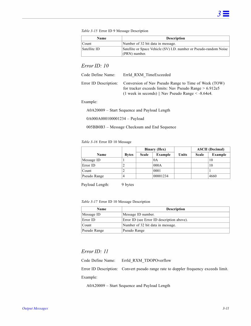
3
Error ID: 10Code Define Name: ErrId_RXM_TimeExceeded
Error ID Description: Conversion of Nav Pseudo Range to Time of Week (TOW) for tracker exceeds limits: Nav Pseudo Range > 6.912e5 (1 week in seconds) || Nav Pseudo Range < -8.64e4.
Example:
A0A20009 – Start Sequence and Payload Length
0A000A000100001234 – Payload
005BB0B3 – Message Checksum and End Sequence
Payload Length: 9 bytes
Error ID: 11Code Define Name: ErrId_RXM_TDOPOverflow
Error ID Description: Convert pseudo range rate to doppler frequency exceeds limit.
Example:
A0A20009 – Start Sequence and Payload Length
Count Number of 32 bit data in message.Satellite ID Satellite or Space Vehicle (SV) I.D. number or Pseudo-random Noise
(PRN) number.
Table 3-16 Error ID 10 Message
Name BytesBinary (Hex)
UnitsASCII (Decimal)
Scale Example Scale ExampleMessage ID 1 0A 10Error ID 2 000A 10Count 2 0001 1Pseudo Range 4 00001234 4660
Table 3-17 Error ID 10 Message Description
Name DescriptionMessage ID Message ID number.Error ID Error ID (see Error ID description above).Count Number of 32 bit data in message.Pseudo Range Pseudo Range
Table 3-15 Error ID 9 Message Description
Name Description
Output Messages 3-11

3
0A000B0001xxxxxxxx – Payload
xxxxB0B3 – Message Checksum and End Sequence
Payload Length: 9 bytes
Error ID: 12Code Define Name: ErrId_RXM_ValidDurationExceeded
Error ID Description: Satellite’s ephemeris age has exceeded 2 hours (7200 s).
Example:
A0A2000D – Start Sequence and Payload Length
0A000C0002xxxxxxxxaaaaaaaa – Payload
xxxxB0B3 – Message Checksum and End Sequence
Table 3-18 Error ID 11 Message
Name BytesBinary (Hex)
UnitsASCII (Decimal)
Scale Example Scale ExampleMessage ID 1 0A 10Error ID 2 000B 11Count 2 0001 1Doppler Frequency 4 xxxxxxxx xxxxxxxx
Table 3-19 Error ID 11 Message Description
Name DescriptionMessage ID Message ID number.Error ID Error ID (see Error ID description above).Count Number of 32 bit data in message.Doppler Frequency Doppler Frequency
3-12 SiRF Binary Protocol Reference Manual—February 2004

3
Payload Length: 13 bytes
Error ID: 13Code Define Name: ErrId_STRTP_BadPostion
Error ID Description: SRAM position is bad during a cold start.
Example:
A0A20011 – Start Sequence and Payload Length
0A000D0003xxxxxxxxaaaaaaaabbbbbbbb – Payload
xxxxB0B3 – Message Checksum and End Sequence
Payload Length: 17 bytes
Table 3-20 Error ID 12 Message
Name BytesBinary (Hex)
UnitsASCII (Decimal)
Scale Example Scale ExampleMessage ID 1 0A 10Error ID 2 000C 12Count 2 0002 2Satellite ID 4 xxxxxxxx xxxxxxxxAge Of Ephemeris 4 aaaaaaaa seconds aaaaaaaa
Table 3-21 Error ID 12 Message Description
Name DescriptionMessage ID Message ID number.Error ID Error ID (see Error ID description above).Count Number of 32 bit data in message.Satellite ID Satellite or Space Vehicle (SV) I.D. number or Pseudo-random Noise
(PRN) numberAge Of Ephemeris The Satellite’s Ephemeris Age in seconds.
Table 3-22 Error ID 13 Message
Name BytesBinary (Hex)
UnitsASCII (Decimal)
Scale Example Scale ExampleMessage ID 1 0A 10Error ID 2 000D 13Count 2 0003 3X 4 xxxxxxxx xxxxxxxxY 4 aaaaaaaa aaaaaaaaZ 4 bbbbbbbb bbbbbbbb
Output Messages 3-13

3
Error ID: 4097 or 0x1001Code Define Name: ErrId_MI_VCOClockLost
Error ID Description: VCO lost lock indicator.
Example:
A0A20009 – Start Sequence and Payload Length
0A1001000100000001 – Payload
001DB0B3 – Message Checksum and End Sequence
Payload Length: 9 bytes
Table 3-23 Error ID 13 Message Description
Name DescriptionMessage ID Message ID number.Error ID Error ID (see Error ID description above).Count Number of 32 bit data in message.X X position in ECEF.Y Y position in ECEF.Z Z position in ECEF.
Table 3-24 Error ID 4097 Message
Name BytesBinary (Hex)
UnitsASCII (Decimal)
Scale Example Scale ExampleMessage ID 1 0A 10Error ID 2 1001 4097Count 2 0001 1VCOLost 4 00000001 1
Table 3-25 Error ID 4097 Message Description
Name DescriptionMessage ID Message ID number.Error ID Error ID (see Error ID description above).Count Number of 32 bit data in message.VCOLost VCO lock lost indicator. If VCOLost != 0, then send failure message.
3-14 SiRF Binary Protocol Reference Manual—February 2004
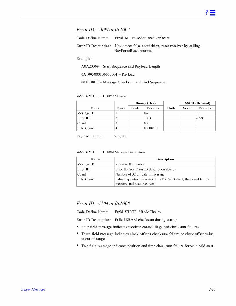
3
Error ID: 4099 or 0x1003Code Define Name: ErrId_MI_FalseAcqReceiverReset
Error ID Description: Nav detect false acquisition, reset receiver by calling NavForceReset routine.
Example:
A0A20009 – Start Sequence and Payload Length
0A1003000100000001 – Payload
001FB0B3 – Message Checksum and End Sequence
Payload Length: 9 bytes
Error ID: 4104 or 0x1008Code Define Name: ErrId_STRTP_SRAMCksum
Error ID Description: Failed SRAM checksum during startup.
• Four field message indicates receiver control flags had checksum failures.
• Three field message indicates clock offset's checksum failure or clock offset value is out of range.
• Two field message indicates position and time checksum failure forces a cold start.
Table 3-26 Error ID 4099 Message
Name BytesBinary (Hex)
UnitsASCII (Decimal)
Scale Example Scale ExampleMessage ID 1 0A 10Error ID 2 1003 4099Count 2 0001 1InTrkCount 4 00000001 1
Table 3-27 Error ID 4099 Message Description
Name DescriptionMessage ID Message ID number.Error ID Error ID (see Error ID description above).Count Number of 32 bit data in message.InTrkCount False acquisition indicator. If InTrkCount <= 1, then send failure
message and reset receiver.
Output Messages 3-15

3
Example:
A0A2xxxx – Start Sequence and Payload Length
0A10080004xxxxxxxaaaaaaaa00000000cccccccc – Payload
xxxxB0B3 – Message Checksum and End Sequence
Payload Length: 21, 17, or 11 bytes
Table 3-28 Error ID 4104 Message
Name BytesBinary (Hex)
UnitsASCII (Decimal)
Scale Example Scale ExampleMessage ID 1 0A 10Error ID 2 1008 4104Count 2 0004 or
0003 or 0002
4 or3 or2
Computed Receiver Control Checksum
4 xxxxxxxx xxxx
Battery-Backed Receiver Control Checksum
4 aaaaaaaa aaaa
Battery-Backed Receiver Control OpMode
4 00000000 0
Battery-Backed Receiver Control Channel Count
4 cccccccc cccc
Compute Clock OffsetChecksum
4 xxxxxxxx xxxx
Battery-Backed Clock Offset Checksum
4 aaaaaaaa aaaa
Battery-Backed Clock Offset
4 bbbbbbbb bbbb
Computed Position Time Checksum
4 xxxxxxxx xxxx
Battery-Backed Position Time Checksum
4 aaaaaaaa aaaa
3-16 SiRF Binary Protocol Reference Manual—February 2004

3
Error ID: 4105 or 0x1009Code Define Name: ErrId_STRTP_RTCTimeInvalid
Error ID Description: Failed RTC SRAM checksum during startup. If one of the double buffered SRAM.Data.LastRTC elements is valid and RTC days is not 255 days, then GPS time and week number computed from the RTC is valid. If not, this RTC time is invalid.
Example:
A0A2000D – Start Sequence and Payload Length
0A10090002xxxxxxxaaaaaaaa – Payload
xxxxB0B3 – Message Checksum and End Sequence
Table 3-29 Error ID 4104 Message Description
Name DescriptionMessage ID Message ID number.Error ID Error ID (see Error ID description above).Count Number of 32 bit data in message.Computed Receiver Control Checksum
Computed receiver control checksum of SRAM.Data.Control structure.
Battery-Backed Receiver Control Checksum
Battery-backed receiver control checksum stored in SRAM.Data.DataBuffer. CntrlChkSum.
Battery-Backed Receiver Control OpMode
Battery-backed receiver control checksum stored in SRAM.Data.Control.OpMode. Valid OpMode values are as follows:OP_MODE_NORMAL = 0,OP_MODE_TESTING = 0x1E51,OP_MODE_TESTING2 = 0x1E52,OP_MODE_TESTING3 = 0x1E53.
Battery-Backed Receiver Control Channel Count
Battery-backed receiver control channel count in SRAM.Data.Control.ChannelCnt.Valid channel count values are 0-12.
Compute Clock OffsetChecksum
Computed clock offset checksum of SRAM.Data.DataBuffer.clkOffset.
Battery-Backed Clock Offset Checksum
Battery-backed clock offset checksum of SRAM.Data.DataBuffer.clkChkSum.
Battery-Backed Clock Offset
Battery-backed clock offset value stored in SRAM.Data.DataBuffer,clkOffset.
Computed Position Time Checksum
Computed position time checksum of SRAM.Data.DataBuffer.postime[1].
Battery-Backed Position Time Checksum
Battery-backed position time checksum of SRAM.Data.DataBuffer.postimeChkSum[1].
Output Messages 3-17

3
Payload Length: 13 bytes
Error ID: 4106 or 0x100ACode Define Name: ErrId_KFC_BackupFailed_Velocity
Error ID Description: Failed battery-backing position because of ECEF velocity sum was greater than equal to 3600.
Example:
A0A20005 – Start Sequence and Payload Length
0A100A0000 – Payload
0024B0B3 – Message Checksum and End Sequence
Payload Length: 5 bytes
Table 3-30 Error ID 4105 Message
Name BytesBinary (Hex)
UnitsASCII (Decimal)
Scale Example Scale ExampleMessage ID 1 0A 10Error ID 2 1009 4105Count 2 0002 2TOW 4 xxxxxxxx seconds xxxxWeek Number 4 aaaaaaaa aaaa
Table 3-31 Error ID 4105 Message Description
Name DescriptionMessage ID Message ID number.Error ID Error ID (see Error ID description above).Count Number of 32 bit data in message.TOW GPS time of week in seconds. Range 0 to 604800 seconds.Week Number GPS week number.
Table 3-32 Error ID 4106 Message
Name BytesBinary (Hex)
UnitsASCII (Decimal)
Scale Example Scale ExampleMessage ID 1 0A 10Error ID 2 100A 4106Count 2 0000 0
3-18 SiRF Binary Protocol Reference Manual—February 2004
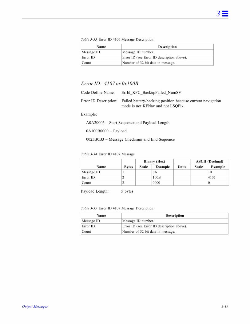
3
Error ID: 4107 or 0x100BCode Define Name: ErrId_KFC_BackupFailed_NumSV
Error ID Description: Failed battery-backing position because current navigation mode is not KFNav and not LSQFix.
Example:
A0A20005 – Start Sequence and Payload Length
0A100B0000 – Payload
0025B0B3 – Message Checksum and End Sequence
Payload Length: 5 bytes
Table 3-33 Error ID 4106 Message Description
Name DescriptionMessage ID Message ID number.Error ID Error ID (see Error ID description above).Count Number of 32 bit data in message.
Table 3-34 Error ID 4107 Message
Name BytesBinary (Hex)
UnitsASCII (Decimal)
Scale Example Scale ExampleMessage ID 1 0A 10Error ID 2 100B 4107Count 2 0000 0
Table 3-35 Error ID 4107 Message Description
Name DescriptionMessage ID Message ID number.Error ID Error ID (see Error ID description above).Count Number of 32 bit data in message.
Output Messages 3-19

3
Error ID: 8193 or 0x2001Code Define Name: ErrId_MI_BufferAllocFailure
Error ID Description: Buffer allocation error occurred. Does not appear to be active because uartAllocError variable never gets set to a non-zero value in the code.
Example:
A0A20009 – Start Sequence and Payload Length
0A2001000100000001 – Payload
002DB0B3 – Message Checksum and End Sequence
Payload Length: 9 bytes
Error ID:8194 or 0x2002Code Define Name: ErrId_MI_UpdateTimeFailure
Error ID Description: PROCESS_1SEC task was unable to complete upon entry. Overruns are occurring.
Example:
A0A2000D – Start Sequence and Payload Length
0A200200020000000100000064 – Payload
0093B0B3 – Message Checksum and End Sequence
Table 3-36 Error ID 8193 Message
Name BytesBinary (Hex)
UnitsASCII (Decimal)
Scale Example Scale ExampleMessage ID 1 0A 10Error ID 2 2001 8193Count 2 0001 1uartAllocError 4 00000001 1
Table 3-37 Error ID 8193 Message Description
Name DescriptionMessage ID Message ID number.Error ID Error ID (see Error ID description above).Count Number of 32 bit data in message.uartAllocError Contents of variable used to signal UART buffer allocation error.
3-20 SiRF Binary Protocol Reference Manual—February 2004

3
Payload Length: 13 bytes
Error ID: 8195 or 0x2003Code Define Name: ErrId_MI_MemoryTestFailed
Error ID Description: Failure of hardware memory test. Does not appear to be active because MemStatus variable never gets set to a non-zero value in the code.
Example:
A0A20005 – Start Sequence and Payload Length
0A20030000 – Payload
002DB0B3 – Message Checksum and End Sequence
Payload Length: 5 bytes
Table 3-38 Error ID 8194 Message
Name BytesBinary (Hex)
UnitsASCII (Decimal)
Scale Example Scale ExampleMessage ID 1 0A 10Error ID 2 2002 8194Count 2 0002 2Number of in process errors.
4 00000001 1
Millisecond errors 4 00000064 100
Table 3-39 Error ID 8194 Message Description
Name DescriptionMessage ID Message ID number.Error ID Error ID (see Error ID description above).Count Number of 32 bit data in message.Number of in process errors
Number of one second updates not complete on entry.
Millisecond errors Millisecond errors caused by overruns.
Table 3-40 Error ID 8195 Message
Name BytesBinary (Hex)
UnitsASCII (Decimal)
Scale Example Scale ExampleMessage ID 1 0A 10Error ID 2 2003 8195Count 2 0000 0
Output Messages 3-21

3
Command Acknowledgment – Message I.D. 11Output Rate: Response to successful input message
This is successful almanac (message ID 0x92) request example:
A0A20002—Start Sequence and Payload Length
0B92—Payload
009DB0B3—Message Checksum and End Sequence
Payload Length: 2 bytes
Command NAcknowledgment – Message I.D. 12 Output Rate: Response to rejected input message
This is an unsuccessful almanac (message ID 0x92) request example:
A0A20002—Start Sequence and Payload Length
0C92—Payload
009EB0B3—Message Checksum and End Sequence
Payload Length: 2 bytes
Visible List – Message I.D. 13Output Rate: Updated approximately every 2 minutes
Table 3-41 Error ID 8195 Message Description
Name DescriptionMessage ID Message ID number.Error ID Error ID (see Error ID description above).Count Number of 32 bit data in message.
Table 3-42 Command Acknowledgment
Name BytesBinary (Hex)
UnitsASCII (Decimal)
Scale Example Scale ExampleMessage ID 1 0B 11Ack. I.D. 1 92 146
Table 3-43 Command NAcknowledgment
Name BytesBinary (Hex)
UnitsASCII (Decimal)
Scale Example Scale ExampleMessage ID 1 0C 12NAck. I.D. 1 92 146
3-22 SiRF Binary Protocol Reference Manual—February 2004

3
Note – This is a variable length message. Only the number of visible satellites are reported (as defined by Visible Svs in Table 3-44).
Example:
A0A2002A—Start Sequence and Payload Length
0D081D002A00320F009C0032....—Payload
....B0B3—Message Checksum and End Sequence
Payload Length: Variable
Almanac Data - Message I.D. 14 Output Rate: Response to poll
Example:
A0A2001E—Start Sequence and Payload Length
0E0111014128FF630D51FD5900A10CC111B454B909098C6CE7
14...............—Payload
09E5B0B3—Message Checksum and End Sequence
Table 3-44 Visible List
Name BytesBinary (Hex)
UnitsASCII (Decimal)
Scale Example Scale ExampleMessage ID 1 0D 13Visible Svs 1 08 8CH 1 - Sv I.D. 1 10 16CH 1 - Sv Azimuth 2 002A degrees 42CH 1 - Sv Elevation 2 0032 degrees 50CH 2 - Sv I.D. 1 0F 15CH 2 - Sv Azimuth 2 009C degrees 156CH 2 - Sv Elevation 2 0032 degrees 50.....
Output Messages 3-23

3
Payload Length: 30 bytes
The data is actually packed and the exact format of this representation and packing method can be extracted from the ICD-GPS-2000 document. The ICD-GPS-2000 document describes the data format of each GPS navigation sub-frame and is available on the web at http://www.arinc.com/gps.
Ephemeris Data (Response to Poll) – Message I.D. 15 The ephemeris data that is polled from the receiver is in a special SiRF format based on the ICD- GPS -200 format for ephemeris data.
Output Rate: Response to poll
Example:
A0 A2 00 5C —Start Sequence and Payload Length
0F 1A 00 1A 00 8B D3 A5 3A 11 01 3B 15 B8 8A 99 FC 88 D4 40 31 3B F2 DD 69 78 00 FF 9E 38 F6 B6 00 1A 00 8B D4 29 DD FB 5C 31 0E F1 79 A6 4D FC 1F 07 AB F1 29 00 F7 A1 0D 12 7F 69 78 7D 00 1A 00 8B D2 2E 00 37 CB F8 C1 D1 00 7F 27 ED E1 D9 2F 2D 16 5A DB D8 FF A2 0C DD F6 F9 —Payload
2A 55 B0 B3—Message Checksum and End Sequence
Table 3-45 Almanac Data
Name BytesBinary (Hex)
NotesScale ExampleMessage I.D. 1 0ESV I.D. 1 01 Satellite PRN Number1
1. Each satellite almanac entry is output in a single message.
Almanac Week & Status
2 1101 First 10 bits is the Almanac week. Next 5 bits have a zero value. Last bit is 1.
Almanac Data 24 ............. This information is taken from the 50BPS navigation message broadcast by the satellite. This information is the last 8 words in the 5th subframe but with the parity removed.2
2. There are 25 possible pages in subframe 5. Pages 1 through 24 contain satellite specific almanac information which is output as part of the almanac data. Page 25 contains health status flags and the almanac week number.
Package Checksum 2 4CA1 This is the checksum of the preceding data in the payload. It is calculated by arranging the previous 26 bytes as 13 half-words and then summing them.3
3. This checksum is not used for serial I/O data integrity. It is used internally for ensuring that almanac information is valid.
3-24 SiRF Binary Protocol Reference Manual—February 2004

3
Payload Length: 92 bytes
The data area consists of a 3x15 array of unsigned integers, 16 bits long. The first word of each row in the array ([0][0], [1][0] and [2][0]) will contain the satellite ID. The remaining words in the row will contain the data from the navigation message subframe, with row [0] containing subframe 1, row [1] containing subframe 2, and row [2] containing subframe 3. Data from the subframe is stored in a packed format, meaning that the 6 parity bits of each 30-bit navigation message word have been removed, and the remaining 3 bytes are stored in 1.5 16-bit words. Since the first word of the subframe, the TLM or telemetry word, does not contain any data needed by the receiver, it is not saved. Thus, there are 9 remaining words, with 3 bytes each, in each subframe. This total of 27 bytes is stored in 14 16-bit words. The second word of the subframe, the HOW or Handoff Word, has its most significant byte (MSB) stored as the least significant byte (LSB) of the first of the 16-bit words. Each following byte is stored in the next available byte of the array. Table 3-47 shows where each byte of the subframe is stored in the row of 16-bit words.
Table 3-46 Ephemeris Data
Name BytesBinary (Hex)
NotesScale ExampleMessage I.D. 1 0F Message I.D.Satellite I.D. 1 1A Satellite PRN Number1
1. Each satellite almanac entry is output in a single message.
Data 90 ... UINT16 [3] [15] array with subframes 1 to 3 data. See description below.
Table 3-47 Byte Positions Between Navigation Message and Data Array
Navigation Message Data ArrayWord Byte Word Byte
2 (HOW) MSB [] [1] LSB2 Middle [] [2] MSB2 LSB [] [2] LSB3 MSB [] [3] MSB3 Middle [] [3] LSB3 LSB [] [4] MSB4 MSB [] [4] LSB4 Middle [] [5] MSB4 LSB [] [5] LSB5 MSB [] [6] MSB5 Middle [] [6] LSB5 LSB [] [7] MSB6 MSB [] [7] LSB6 Middle [] [8] MSB6 LSB [] [8] LSB7 MSB [] [9] MSB7 Middle [] [9] LSB7 LSB [] [10] MSB8 MSB [] [10] LSB8 Middle [] [11] MSB
Output Messages 3-25

3
Note – Message ID 149 uses the same format, except the Satellite ID (the second byte in Message ID 15) is omitted. Message ID 149 is thus a 91-byte message. The satellite ID is still embedded in elements [0][0], [1][0] and [2][0] of the data array.
Test Mode 1 - Message I.D. 16 Output Rate: Variable - set by the period as defined in message ID 150
Example:
A0A20011—Start Sequence and Payload Length
100015001E000588B800C81B5800040001—Payload
02D8B0B3—Message Checksum and End Sequence
8 LSB [] [11] LSB9 MSB [] [12] MSB9 Middle [] [12] LSB9 LSB [] [13] MSB10 MSB [] [13] LSB10 Middle [] [14] MSB10 LSB [] [14] LSB
Table 3-47 Byte Positions Between Navigation Message and Data Array
Navigation Message Data ArrayWord Byte Word Byte
3-26 SiRF Binary Protocol Reference Manual—February 2004

3
Payload Length: 17 bytes
Differential Corrections - Message I.D. 17Message I.D. 17 provides the RTCM data received from a DGPS source. The data is sent as a SiRF Binary message and is based on the RTCM SC-104 format. For more information see RTCM Recommended Standards for Differential GNSS by the Radio Technical Commission for Maritime Services.
Table 3-48 Test Mode 1 Data
Name BytesBinary (Hex)
UnitsASCII (Decimal)
Scale Example Scale ExampleMessage ID 1 10 16SV ID 2 0015 21Period 2 001E sec 30Bit Sync Time 2 0005 sec 5Bit Count 2 88B8 35000Poor Status 2 00C8 200Good Status 2 1B58 7000Parity Error Count 2 0004 4Lost VCO Count 2 0001 1
Table 3-49 Detailed Description of Test Mode 1 Data
Name DescriptionMessage I.D. Message I.D. number.SV ID The number of the satellite being tracked.Period The total duration of time (in seconds) that the satellite is tracked.Bit Sync Time The time it takes for channel 0 to achieve the status of 37.Bit Count The total number of data bits that the receiver is able to demodulate
during the test period. As an example, for a 20 second test period, the total number of bits that can be demodulated by the receiver is 12000 (50BPS x 20sec x 12 channels).
Poor Status This value is derived from phase accumulation time. Phase accumulation is the amount of time a receiver maintains phase lock. Every 100msec of loss of phase lock equates to 1 poor status count. As an example, the total number of status counts for a 60 second period is 7200 (12 channels x 60 sec x 10 sec).
Good Status This value is derived from phase accumulation time. Phase accumulation is the amount of time a receiver maintains phase lock. Every 100msec of phase lock equates to 1 good status count.
Parity Error Count The number of word parity errors. This occurs when the transmitted parity word does not match the receivers parity check.
Lost VCO Count The number of 1 msec VCO lost lock was detected. This occurs when the PLL in the RFIC loses lock. A significant jump in crystal frequency and / or phase causes a VCO lost lock.
Output Messages 3-27

3
OkToSend - Message I.D. 18Output Rate: Trickle Power CPU on/off indicator
Example:
A0A20002—Start Sequence and Payload Length
1200—Payload
0012B0B3—Message Checksum and End Sequence
Navigation Parameters (Response to Poll) – Message I.D. 19 Output Rate: 1 Response to Poll
Example:
A0 A2 00 41 —Start Sequence and Payload Length
13 00 00 00 00 00 00 00 00 01 1E 0F 01 00 01 00 00 00 00 04 00 4B 1C 00 00 00 00 02 00 1E 00 00 00 00 00 00 00 03 E8 00 00 03 E8 00 00 00 00 00 00 00 00 00 00 00 00 00 00 00 00 00 00 00 00 00 00—Payload
02 A4 B0 B3—Message Checksum and End Sequence
Table 3-50 Almanac Data
Name BytesBinary (Hex)
UnitsASCII (Decimal)
Scale Example Scale ExampleMessage I.D. 1 12 12Send Indicator1
1. 0 implies that CPU is about to go OFF, OkToSend==NO, 1 implies CPU has just come ON, OkToSend==YES
1 00 00Payload Length: 2 bytes
Table 3-51 Navigation Parameters
Name BytesBinary (Hex)
UnitsASCII (Decimal)
Scale Example Scale ExampleMessage ID 1 13 19Sub ID1 1 00Reserved 3 00Altitude Hold Mode 1 00Altitude Hold Source 1 00Altitude Source Input 2 0000 metersDegraded Mode2 1 00Degraded Timeout 1 00 secondsDR Timeout 1 01 secondsTrack Smooth Mode 1 1EStatic Navigation 1 0F3SV Least Squares 1 01Reserved 4 00000000DOP Mask Mode3 1 04Navigation Elevation Mask 2 004B
3-28 SiRF Binary Protocol Reference Manual—February 2004

3
Table 3-52 Horizontal/Vertical Error
Navigation Power Mask 1 1CReserved 4 00000000DGPS Source 1 02DGPS Mode4 1 00 DGPS Timeout 1 1E secondsReserved 4 00000000 LP Push-to-Fix 1 00LP On-time 4 000003E8 LP Interval 4 000003E8 User Tasks Enabled5 1 00User Task Interval 4 00000000 LP Power Cycling Enabled 1 00 LP Max. Acq. Search Time 4 00000000 secondsLP Max. Off Time 4 00000000 secondsAPM Enabled/Power Duty Cycle6
1 00
Number of Fixes 2 0000 Time Between Fixes 2 0000 secondsHorizontal/Vertical Error Max7
1 00 meters
Response Time Max 1 00 secondsTime/Accuracy & Time/Duty Cycle Priority8
1 00
Payload Length: 65 bytes1. 00=GSW2 Definition, 01=SiRF Binary APM Definition, >02=Reserved
2. See Table 2-17.3. See Table 2-20.4. See Table 2-22.5. User task enabled - scheduled from 100ms interrupt and the idle loop.
6. Bit7: APM Enabled, 1: Enabled, 0: Disabled, Bit 4-0: power duty cycle, Range: 1-20 scaled to 5%, 1: 5%, 2: 10% … 20:100%
7. See Table 3-52
8. Bit 3-2: Time accuracy, 0x00 = No priority imposed, 0x01 = RESP_TIME_MAX has higher priority, 0x02 = HORI_ERR_MAX has higher priority, Bit 1-0: time duty cycle, 0x01 = Time between two consecutive fixes has priority, 0x02 = Power Duty cycle has higher priority
Value Position Error (in meters)0x00 < 1 meter0x01 < 5 meter0x02 < 10 meter0x03 < 20 meter0x04 < 40 meter0x05 < 80 meter0x06 < 160 meter0x07 No Maximum0x08 - 0xFF Reserved
Table 3-51 Navigation Parameters (Continued)
Name BytesBinary (Hex)
UnitsASCII (Decimal)
Scale Example Scale Example
Output Messages 3-29

3
Test Mode 2/3/4 - Message I.D. 20The definition of MID 20 is different depending on the version and type of software being used. For GSW2, MID 20 is defined as Test Mode 2 only. For SiRFLoc or SiRFXTrac, MID can be either Test Mode 2, Test Mode 3, or Test Mode 4. For GSW2 software, refer to MID 46 for test mode 3 and test mode 4 results.
Output Rate: Variable - set by the period as defined in message ID 150
Test Mode 2This is supported by either GSW2, SiRFLoc, or SiRFXTrac. Test Mode 2 requires approximately 1.5 minutes of data collection before sufficient data is available.
Example:
A0A20033—Start Sequence and Payload Length
140001001E00023F70001F0D2900000000000601C600051B0E000EB41A00000000000000000000000000000000000000000000—Payload
0316B0B3—Message Checksum and End Sequence
Payload Length: 51 bytes
Table 3-53 Test Mode 2 Message
Name BytesBinary (Hex)
UnitsASCII (Decimal)
Scale Example Scale ExampleMessage ID 1 14 20SV ID 2 0001 1Period 2 001E sec 30Bit Sync Time 2 0002 sec 2Bit Count 2 3F70 13680Poor Status 2 001F 31Good Status 2 0D29 3369Parity Error Count 2 0000 0Lost VCO Count 2 0000 0Frame Sync Time 2 0006 sec 6C/No Mean 2 *10 01C6 ÷10 45.4C/No Sigma 2 *10 0005 ÷10 0.5Clock Drift 2 *10 1B0E Hz ÷10 692.6Clock Offset 4 *10 000EB41A Hz ÷10 96361.0Reserved 2 0000Reserved 4 00000000Reserved 4 00000000Reserved 4 00000000Reserved 4 00000000Reserved 4 00000000
Table 3-54 Detailed Description of Test Mode 2 Message
Name DescriptionMessage I.D. Message I.D. number.SV ID The number of the satellite being tracked.
3-30 SiRF Binary Protocol Reference Manual—February 2004

3
Test Mode 3This is supported by SiRFLoc and SiRFXTrac only as MID 20. Test Mode 3 requires approximately 10 seconds of data collection before sufficient data is available.
Example:
A0A20033—Start Sequence and Payload Length
140001001E00023F70001F0D2900000000000601C600051B0E000EB41A00000000000000000000000000000000000000000000—Payload
0316B0B3—Message Checksum and End Sequence
Period The total duration of time (in seconds) that the satellite is tracked.Bit Sync Time The time it takes for channel 0 to achieve the status of 37.Bit Count The total number of data bits that the receiver is able to demodulate
during the test period. As an example, for a 20 second test period, the total number of bits that can be demodulated by the receiver is 12000 (50BPS x 20sec x 12 channels).
Poor Status This value is derived from phase accumulation time. Phase accumulation is the amount of time a receiver maintains phase lock. Every 100msec of loss of phase lock equates to 1 poor status count. As an example, the total number of status counts for a 60 second period is 7200 (12 channels x 60 sec x 10 sec)
Good Status This value is derived from phase accumulation time. Phase accumulation is the amount of time a receiver maintains phase lock. Every 100msec of phase lock equates to 1 good status count.
Parity Error Count The number of word parity errors. This occurs when the transmitted parity word does not match the receivers parity check.
Lost VCO Count The number of 1 msec VCO lost lock was detected. This occurs when the PLL in the RFIC loses lock. A significant jump in crystal frequency and / or phase will cause a VCO lost lock.
Frame Sync The time it takes for channel 0 to reach a 3F status.C/No Mean Calculated average of reported C/No by all 12 channels during the test
period.C/No Sigma Calculated sigma of reported C/No by all 12 channels during the test
period.Clock Drift Difference in clock frequency from start and end of the test period.Clock Offset The internal clock offset.
Table 3-55 Test Mode 3 Message
Name BytesBinary (Hex)
UnitsASCII (Decimal)
Scale Example Scale ExampleMessage ID 1 14 20SV ID 2 0001 1Period 2 001E sec 30Bit Sync Time 2 0002 sec 2Bit Count 2 3F70 13680Poor Status 2 001F 31Good Status 2 0D29 3369
Table 3-54 Detailed Description of Test Mode 2 Message
Name Description
Output Messages 3-31

3
Payload Length: 51 bytes
Parity Error Count 2 0000 0Lost VCO Count 2 0000 0Frame Sync Time 2 0006 sec 6C/No Mean 2 *10 01C6 ÷10 45.4C/No Sigma 2 *10 0005 ÷10 0.5Clock Drift 2 *10 1B0E Hz ÷10 692.6Clock Offset 4 *10 000EB41A Hz ÷10 96361.0Bad 1Khz Bit Count 2 0000Abs I20ms 4 00000000Abs Q1ms 4 00000000Reserved 4 00000000Reserved 4 00000000Reserved 4 00000000
Table 3-56 Detailed Description of Test Mode 3 Message
Name DescriptionMessage I.D. Message I.D. number.SV ID The number of the satellite being tracked.Period The total duration of time (in seconds) that the satellite is tracked.Bit Sync Time The time it takes for channel 0 to achieve the status of 37.Bit Count The total number of data bits that the receiver is able to demodulate
during the test period. As an example, for a 20 second test period, the total number of bits that can be demodulated by the receiver is 12000 (50BPS x 20sec x 12 channels).
Poor Status This value is derived from phase accumulation time. Phase accumulation is the amount of time a receiver maintains phase lock. Every 100msec of loss of phase lock equates to 1 poor status count. As an example, the total number of status counts for a 60 second period is 7200 (12 channels x 60 sec x 10 sec)
Good Status This value is derived from phase accumulation time. Phase accumulation is the amount of time a receiver maintains phase lock. Every 100msec of phase lock equates to 1 good status count.
Parity Error Count The number of word parity errors. This occurs when the transmitted parity word does not match the receivers parity check.
Lost VCO Count The number of 1 msec VCO lost lock was detected. This occurs when the PLL in the RFIC loses lock. A significant jump in crystal frequency and / or phase will cause a VCO lost lock.
Frame Sync The time it takes for channel 0 to reach a 3F status.C/No Mean Calculated average of reported C/No by all 12 channels during the test
period.C/No Sigma Calculated sigma of reported C/No by all 12 channels during the test
period.Clock Drift Difference in clock frequency from start and end of the test period.Clock Offset The internal clock offset.Bad 1Khz Bit Count Errors in 1ms post correlation I count values.Abs I20ms Absolute value of the 20ms coherent sums of the I count over the
duration of the test period.
Table 3-55 Test Mode 3 Message (Continued)
Name BytesBinary (Hex)
UnitsASCII (Decimal)
Scale Example Scale Example
3-32 SiRF Binary Protocol Reference Manual—February 2004

3
Test Mode 4This is supported by SiRFLoc and SiRFXTrac only.
Table 3-57 Test Mode 4 Message
Payload Length: 29 bytes
Abs Q1ms Absolute value of the 1ms Q count over the duration of the test period.
Name BytesBinary (Hex)
UnitsASCII (Decimal)
Scale Example Scale ExampleMessage ID 1 14 20Test Mode 1 04 4Message Variant 1 01 1SV ID 2 0001 1Period 2 001E sec 30Bit Sync Time 2 0002 sec 2C/No Mean 2 *10 01C6 ÷10 45.4C/No Sigma 2 *10 0005 ÷10 0.5Clock Drift 2 *10 1B0E Hz ÷10 692.6Clock Offset 4 *10 000EB41A Hz ÷10 96361.0I Count Errors 2 0003 3Abs I20ms 4 0003AB88 240520Abs Q1ms 4 0000AFF0 45040
Table 3-58 Detailed Description of Test Mode 4 Message
Name DescriptionMessage I.D. Message I.D. number.Test Mode 3=Testmode 3, 4=Testmode 4Message Variant The variant # of the message (variant change indicates possible change
in number of fields or field description).SV ID The number of the satellite being tracked.Period The total duration of time (in seconds) that the satellite is tracked.Bit Sync Time The time it takes for channel 0 to achieve the status of 37.C/No Mean Calculated average of reported C/No by all 12 channels during the test
period.C/No Sigma Calculated sigma of reported C/No by all 12 channels during the test
period.Clock Drift Difference in clock frequency from start and end of the test period.Clock Offset The internal clock offset.I Count Errors Errors in 1ms post correlation I count values.Abs I20ms Absolute value of the 20ms coherent sums of the I count over the
duration of the test period.Q 1ms Absolute value of the 1ms Q count over the duration of the test period.
Table 3-56 Detailed Description of Test Mode 3 Message
Name Description
Output Messages 3-33

3
Navigation Library Measurement Data - Message I.D. 28Output Rate: Every measurement cycle (full power / continuous: 1Hz)
Example:
A0A20038—Start Sequence and Payload Length
1C00000660D015F143F62C4113F42F417B235CF3FBE95E468C6964B8FBC582415CF1C375301734.....03E801F400000000—Payload
1533B0B3—Message Checksum and End Sequence
For GPS Software Time, Psuedorange, Carrier Frequency, and Carrier Phase, the fields are either floating point (4-byte fields) or double-precision floating point (8-byte fields), per IEEE-754 format. The byte order may have to be changed to be interpreted properly on some computers. Also, the byte order differs between GPS software versions 2.2.0 and earlier, and versions 2.3.0 and later.
Table 3-59 Measurement Data
Name BytesBinary (Hex)
UnitsASCII (Decimal)
Scale Example Scale ExampleMessage I.D. 1 1C 28Channel 1 00 0Time Tag 4 000660D0 milli-sec 135000Satellite ID 1 15 20GPS Software Time 8 F143F62C
4113F42Fmilli-sec 2.4921113
696e+005Pseudorange 8 417B235C
F3FBE95Em 2.1016756
638e+007Carrier Frequency 4 468C6964 m/sec 1.6756767
578e+004Carrier Phase 8 B8FBC582
415CF1C3m 4.4345542
262e+004Time in Track 2 7530 milli-sec 10600Sync Flags 1 17 23C/No 1 1 34 dB-Hz 43C/No 2 1 dB-Hz 43C/No 3 1 dB-Hz 43C/No 4 1 dB-Hz 43C/No 5 1 dB-Hz 43C/No 6 1 dB-Hz 43C/No 7 1 dB-Hz 43C/No 8 1 dB-Hz 43C/No 9 1 dB-Hz 43C/No 10 1 dB-Hz 43Delta Range Interval 2 03E801F4 m 1000Mean Delta Range Time 2 01F4 milli-sec 500Extrapolation Time 2 0000 milli-secPhase Error Count 1 00 0Low Power Count 1 00 0Payload Length: 56 bytes
3-34 SiRF Binary Protocol Reference Manual—February 2004

3
To convert the data to be properly interpreted on a PC-compatible computer, do the following:
For double-precision (8-byte) values: Assume the bytes are transmitted in the order of B0, B1, ... , B7. For version 2.2.0 and earlier software, rearrange them to B3, B2, B1, B0, B7, B6, B5. B4 For version 2.3.0 and later software, rearrange them to B7, B6, B5, ... , B0
For single-precision (4-byte) values: Assume bytes are transmitted in the order of B0, B1, B2 , B3 Rearrange them to B3, B2, B1, B0 (that is, byte B3 goes into the lowest memory address, B0 into the highest)
With these remappings, the values should be correct. To verify, compare the same field from several satellites tracked at the same time. The reported exponent should be similar (within 1 power of 10) among all satellites. The reported Carrier Frequency contains a bias of the clock drift reported in MID 7. To adjust the reported carrier frequency do the following:
Corrected Carrier Frequency (m/s) = Reported Carrier Frequency (m/s) - Clock Drift (Hz) / 1575420000 Hz For a nominal clock drift value of 96.25 kHz (equal to a GPS Clock frequency of 24.5535 MHz), the correction value is 18315.766 m/s.
Output Messages 3-35

3
Table 3-60 Sync Flag Fields
Bit Fields Description[0] Coherent Integration Time
0 = 2ms1 = 10ms
[2:1] Synch State00 = Not aligned01 = Consistent code epoch alignment10 = Consistent data bit alignment11 = No millisecond errors
[4:3] Autocorrelation Detection State00 = Verified not an autocorrelation01 = Testing in progress10 = Strong signal, autocorrelation detection not run11 = Not used
Table 3-61 Detailed Description of the Measurement Data
Name DescriptionMessage I.D. Message I.D. number.Channel Receiver channel number for a given satellite being searched or
tracked.Time Tag This is the Time Tag in milliseconds of the measurement block in the
receiver software time.Satellite ID Satellite or Space Vehicle (SV) I.D. number or Pseudo-random Noise
(PRN) number.GPS Software Time This is GPS Time or Time of Week (TOW) estimated by the software
in milliseconds.Pseudo-range This is the generated pseudo range measurement for a particular SV.Carrier Frequency This is can be interpreted in two ways:
1) The delta-pseudo range normalized by the reciprocal of the delta pseudo range measurement interval.2) The frequency from the AFC loop. If, for example, the delta pseudo range interval computation for a particular channel is zero, then it can be the AFC measurement, otherwise it is a delta-pseudo range computation.
Carrier Phase This is the integrated carrier phase given in meters.Time in Track The Time in Track counts how long a particular SV has been in track.
For any count greater than zero (0), a generated pseudo range is present for a particular channel. The length of time in track is a measure of how large the pull-in error may be.
Sync Flags This byte contains two a two bit fields that report the integration inter-val and sync value achieved for a particular channel.1) Bit 0: Coherent Integration Interval (0 = 2 milliseconds, 1 = 10 milli-
seconds)2) Bits: (1 2) = Synchronization3) Bit: (2 1)
Value: {0 0} Not AlignedValue: {0 1} Consistent Code Epoch AlignmentValue: {1 0} Consistent Data Bit Alignment
Value: {1 1} No Millisecond Errors
3-36 SiRF Binary Protocol Reference Manual—February 2004

3
Navigation Library DGPS Data - Message I.D. 29Output Rate: Every measurement cycle (full power / continuous : 1Hz)
Example:
A0A2001A—Start Sequence and Payload Length
1D000F00B501BFC97C673CAAAAAB3FBFFE1240A0000040A00000—Payload
0956B0B3—Message Checksum and End Sequence
C/No 1 This array of Carrier To Noise Ratios is the average signal power in dB-Hz for each of the 100-millisecond intervals in the previous second or last epoch for each particular SV being track in a channel.
First 100 millisecond measurementC/No 2 Second 100 millisecond measurementC/No 3 Third 100 millisecond measurementC/No 4 Fourth 100 millisecond measurementC/No 5 Fifth 100 millisecond measurementC/No 6 Sixth 100 millisecond measurementC/No 7 Seventh 100 millisecond measurementC/No 8 Eighth 100 millisecond measurementC/No 9 Ninth 100 millisecond measurementC/No 10 Tenth 100 millisecond measurementDelta Range Interval This is the delta-pseudo range measurement interval for the preceding
second. A value of zero indicated that the receiver has an AFC measurement or no measurement in the Carrier Frequency field for a particular channel.
Mean Delta Range Time This is the mean calculated time of the delta-pseudo range interval in milliseconds measured from the end of the interval backwards
Extrapolation Time This is the pseudo range extrapolation time in milliseconds, to reach the common Time tag value.
Phase Error Count This is the count of the phase errors greater than 60 Degrees measured in the preceding second as defined for a particular channel.
Low Power Count This is the low power measurements for signals less than 28 dB-Hz in the preceding second as defined for a particular channel
Table 3-61 Detailed Description of the Measurement Data (Continued)
Name Description
Output Messages 3-37

3
Note – The fields Pseudorange Correction, Pseudorange Rate Correction and Correction Age, are floating point values per IEEE-754. To properly interpret these in a PC, the bytes need to be rearranged into reverse order
Navigation Library SV State Data - Message I.D. 30The data in Message I.D. 30 reports the computed satellite position and velocity at the specified GPS time.
Output Rate: Every measurement cycle (full power / continuous : 1Hz)
Example:
A0A20053—Start Sequence and Payload Length
1E15....2C64E99D01....408906C8—Payload
2360B0B3—Message Checksum and End Sequence
Table 3-62 Measurement Data
Name BytesBinary (Hex)
UnitsASCII (Decimal)
Scale Example Scale ExampleMessage I.D. 1 1D 29Satellite ID 2 000F 15IOD 2 00B5 181Source1
1. 0 = Use no corrections, 1 = Use WAAS channel, 2 = Use external source, 3 = Use Internal Beacon, 4 = Set DGPS Corrections
1 01 1Pseudo-range Correction 4 BFC97C67 m -1.574109Pseudo-range rate Correction
4 3CAAAAAB
m/sec 0.020833
Correction Age 4 3FBFFE12 sec 1.499941Reserved 4Reserved 4Payload Length: 26 bytes
Table 3-63 SV State Data
Name BytesBinary (Hex)
UnitsASCII (Decimal)
Scale Example Scale ExampleMessage I.D. 1 1E 30Satellite ID 1 15 21GPS Time 8 secPosition X 8 mPosition Y 8 mPosition Z 8 mVelocity X 8 m/secVelocity Y 8 m/secVelocity Z 8 m/secClock Bias 8 sec
3-38 SiRF Binary Protocol Reference Manual—February 2004

3
Note – Each of the 8 byte fields as well as Clock Drift and Ionospheric Delay fields are floating point values per IEEE-754. To properly interpret these in a PC, the bytes need to be rearranged into reverse order
Navigation Library Initialization Data - Message I.D. 31Output Rate: Every measurement cycle (full power / continuous : 1Hz)
Example:
A0A20054—Start Sequence and Payload Length
1F....00000000000001001E000F....00....000000000F....00....02....043402....
....02—Payload
0E27B0B3—Message Checksum and End Sequence
Clock Drift 4 2C64E99D s/s 744810909Ephemeris Flag1 1 01 1Reserved 4Reserved 4Ionospheric Delay 4 408906C8 m 1082721992Payload Length: 83 bytes
1. 0 = no valid SV state, 1 = SV state calculated from ephemeris, 2 = Satellite state calculated from almanac
Table 3-64 Measurement Data
Name BytesBinary (Hex)
UnitsASCII (Decimal)
Scale Example Scale ExampleMessage I.D. 1 1F 31Reserved 1Altitude Mode1 1 00 0Altitude Source 1 00 0Altitude 4 00000000 m 0Degraded Mode2 1 01 1Degraded Timeout 2 001E sec 30Dead-reckoning Timeout 2 000F sec 15Reserved 2Track Smoothing Mode3 1 00 0Reserved 1Reserved 2Reserved 2Reserved 2DGPS Selection4 1 00 0DGPS Timeout 2 0000 sec 0
Table 3-63 SV State Data
Name BytesBinary (Hex)
UnitsASCII (Decimal)
Scale Example Scale Example
Output Messages 3-39

3
Elevation Nav. Mask 2 000F 15Reserved 2Reserved 1Reserved 2Reserved 1Reserved 2Static Nav. Mode5 1 00 0Reserved 2Position X 8 mPosition Y 8 mPosition Z 8 mPosition Init. Source6 1 02 2GPS Time 8
Table 3-64 Measurement Data (Continued)
Name BytesBinary (Hex)
UnitsASCII (Decimal)
Scale Example Scale Example
3-40 SiRF Binary Protocol Reference Manual—February 2004

3
Geodetic Navigation Data - Message I.D. 41Output Rate:Every measurement cycle (full power / continuous : 1Hz)
Example:
A0 A2 00 5B—Start Sequence and Payload Length
29 00 00 02 04 04 E8 1D 97 A7 62 07 D4 02 06 11 36 61 DA 1A 80 01 58 16 47 03 DF B7 55 48 8F FF FF FA C8 00 00 04 C6 15 00 00 00 00 00 00 00 00 00 00 00 00 00 BB 00 00 01 38 00 00 00 00 00 00 6B 0A F8 61 00 00 00 00 00 1C 13 14 00 00 00 00 00 00 00 00 00 00 00 00 08 05 00—Payload
11 03 B0 B3—Message Checksum and End Sequence
GPS Week 2 0434 1076Time Init. Source7 1 02 2Drift 8Drift Init. Source8 1 02 2Payload Length: 84 bytes
1. 0 = Use last know altitude 1 = Use user input altitude 2 = Use dynamic input from external source2. 0 = Use direction hold and then time hold 1 = Use time hold and then direction hold 2 = Only use direction
hold 3 = Only use time hold 4 = Degraded mode is disabled3. 0 = True 1 = False4. 0 = Use DGPS if available 1 = Only navigate if DGPS corrections are available 2 = Never use DGPS
corrections5. 0 = True 1 = False6. 0 = ROM position 1 = User position 2 = SRAM position 3 = Network assisted position7. 0 = ROM time 1 = User time 2 = SRAM time 3 = RTC time 4 = Network assisted time8. 0 = ROM clock 1 = User clock 2 = SRAM clock 3 = Calibration clock 4 = Network assisted clock
Table 3-65 Measurement Data
Name BytesBinary (Hex)
UnitsASCII (Decimal)
Scale Example Scale Example
Message ID 1 41
Nav Valid 2 NAV Type 2 Extended Week Num-ber
2 week
TOW 4 secUTC Year 2 yearUTC Month 1 monthUTC Day 2 dayUTC Hour 2 hrUTC Minute 2 minUTC Second 2 sec
Table 3-64 Measurement Data (Continued)
Name BytesBinary (Hex)
UnitsASCII (Decimal)
Scale Example Scale Example
Output Messages 3-41

3
Note – Values are transmitted as integer values. When scaling is indicated in the Description, the decimal value has been multiplied by the indicated amount and then converted to an integer. Example: Value transmitted: 2345; indicated scaling: 102; actual value: 23.45.
Satellite ID List 4 Latitude 4 degLongitude 4 degAltitude from Ellipsoid 4 metersAltitude from MSL 4 meters
Map Datum1 1 Speed Over Ground (SOG)
2 m/sec
Course Over Ground (COG, True)
2 deg
Magnetic Variation 2 degClimb Rate 2 m/secHeading Rate 2 deg
/secEstimated Horizontal Position Error (EHPE)
4 meters
Estimated Vertical Position Error (EVPE)
4 meters
Estimated Time Error (ETE)
4 meters
Estimated Horizontal Velocity Error (EHVE)
2 m/sec
Clock Bias 4 metersClock Bias Error 4 metersClock Drift 4 m/secClock Drift Error 4 metersDistance Traveled since RESET
4 meters
Distance Traveled error 2 metersHeading Error 2 degNumber of SVs in Fix 1HDOP 1
Reserved 1 Payload Length: 91 bytes
1. Map Datum indicates the datum to which latitude, longitude and altitude relate. 0 = WGS-84, by default. Other values will be defined as other datums are implemented.
Table 3-65 Measurement Data (Continued)
Name BytesBinary (Hex)
UnitsASCII (Decimal)
Scale Example Scale Example
3-42 SiRF Binary Protocol Reference Manual—February 2004

3
Table 3-66 Detailed Description of Geodetic Navigation Data Message
Name Description
Message ID Message I.D. number.
Nav Valid Any bits not 0: Nav is Invalid Bit 0=1: Position fix not validatedBit 1=1: Reserved (EHPE limits exceeded)Bit 2=1: Reserved (EVPE limits exceeded)Bit 3=1: DR data InvalidBit 4=1: DR Cal InvalidBit 5=1: GPS-based Cal not AvailableBit 6=1: DR Pos InvalidBit 7=1: DR Heading InvalidBit 8-15=1: Undefined
NAV Type NAV Mode Bits definition: GPS Fix Type: bits 2-0: SVs Used 000 No Nav 001 1 SV solution 010 2 SV solution 011 3 SV solution (2D) 100 4 or More SV (3D) 101 Least Sq 2D fix 110 Least Sq 3D fix 111 DR solution (0 SV) bit 3 =1: Trickle Power On bits 5-4 Altitude hold 00 No Altitude Hold 01 Filter Altitude used 10 Use Altitude used 11 User Forced Altitude bit 6 = 1: SIRFDRIVE On bit 7 = 1: DGPS corrections bit 8 = 1: Sensor Based DR bit 9 = 1: Sol Validated bit 10 = 1: VEL DR Timeout bit 11 = 1: Edited by UI bit 12 = 1: Velocity Validbit 13 = 1: Altitude hold is disabledbit 14-15 =1: Sensor DR status, 00=GPS only solution, 01=DR Calibration from GPS, 10=DR Sensor Error, 11=DR is in test
Extended Week Number Range: 800 to 500TOW Range: 0 to 604800.00UTC Year Range: 1980 to 3000UTC Month Range: 1 to 12UTC Day Range: 1 to 31UTC Hour Range: 0 to 23
Output Messages 3-43

3
Test Mode 3/4 - Message I.D. 46
Note – This message is used in GSW2 software only. For SiRFLoc and SiRFXTrac software, refer to MID 20.
Output Rate: Variable - set by the period as defined in message ID 150
Example:
A0A20033—Start Sequence and Payload Length
2E0001001E00023F70001F0D2900000000000601C600051B0E000EB41A00000000000000000000000000000000000000000000—Payload
0316B0B3—Message Checksum and End Sequence
UTC Minute Range: 0 to 60UTC Second Range: 0 to 60Number of Satellites in Solution Range: 0 -12Latitude Range: -90 to 90Longitude Range: -180 to 180Altitude from Ellipsoid Range: -2000 to 100000.0Altitude from MSL Range: -2000 to 100000.0Map Datum Range: 0-255Speed Over Ground (SOG) Range: 0-655Course Over Ground (COG, True) Range: 0 to 360Magnetic Variation Range: -90 to 90Climb Rate Range: -300 to 300Heading Rate Range: -300 to 300Estimated Horizontal Position Error (EHPE) Range: 0 to 6000000Estimated Vertical Position Error (EVPE) Range: 0 to 24000Estimated Time Error (ETE) Range: 0 to 6000000Estimated Horizontal Velocity Error (EHVE) Range: 0 to 655Clock Bias Range: -90000 to 90000Clock Bias Error Range: 0 to 6000000Clock Drift Range: -1000 to 1000Clock Drift Error Range: 0 to 1000Distance Traveled since RESET Range: 0 to 4294967295Distance Traveled error Range: 65535Heading Error Range: 0 to 180Number of SVs in Fix Count of satellites indicated by SVID listHDOP Horizontal Dilution of PrecisionReserved Reserved
Table 3-67 Test Mode 3 Message
Name BytesBinary (Hex)
UnitsASCII (Decimal)
Scale Example Scale ExampleMessage ID 1 2E 46SV ID 2 0001 1
Table 3-66 Detailed Description of Geodetic Navigation Data Message
Name Description
3-44 SiRF Binary Protocol Reference Manual—February 2004

3
Payload Length: 51 bytes
Period 2 001E sec 30Bit Sync Time 2 0002 sec 2Bit Count 2 3F70 13680Poor Status 2 001F 31Good Status 2 0D29 3369Parity Error Count 2 0000 0Lost VCO Count 2 0000 0Frame Sync Time 2 0006 sec 6C/No Mean 2 *10 01C6 ÷10 45.4C/No Sigma 2 *10 0005 ÷10 0.5Clock Drift 2 *10 1B0E Hz ÷10 692.6Clock Offset 4 *10 000EB41A Hz ÷10 96361.0Bad 1Khz Bit Count 2 0000Abs I20ms 4 00000000Abs Q1ms 4 00000000Reserved 4 00000000Reserved 4 00000000Reserved 4 00000000
Table 3-68 Detailed Description of Test Mode 3 Message
Name DescriptionMessage I.D. Message I.D. number.SV ID The number of the satellite being tracked.Period The total duration of time (in seconds) that the satellite is tracked.Bit Sync Time The time it takes for channel 0 to achieve the status of 37.Bit Count The total number of data bits that the receiver is able to demodulate
during the test period. As an example, for a 20 second test period, the total number of bits that can be demodulated by the receiver is 12000 (50BPS x 20sec x 12 channels).
Poor Status This value is derived from phase accumulation time. Phase accumulation is the amount of time a receiver maintains phase lock. Every 100msec of loss of phase lock equates to 1 poor status count. As an example, the total number of status counts for a 60 second period is 7200 (12 channels x 60 sec x 10 sec)
Good Status This value is derived from phase accumulation time. Phase accumulation is the amount of time a receiver maintains phase lock. Every 100msec of phase lock equates to 1 good status count.
Parity Error Count The number of word parity errors. This occurs when the transmitted parity word does not match the receivers parity check.
Lost VCO Count The number of 1 msec VCO lost lock was detected. This occurs when the PLL in the RFIC loses lock. A significant jump in crystal frequency and / or phase will cause a VCO lost lock.
Frame Sync The time it takes for channel 0 to reach a 3F status.C/No Mean Calculated average of reported C/No by all 12 channels during the test
period.C/No Sigma Calculated sigma of reported C/No by all 12 channels during the test
period.
Table 3-67 Test Mode 3 Message (Continued)
Name BytesBinary (Hex)
UnitsASCII (Decimal)
Scale Example Scale Example
Output Messages 3-45

3
Test Mode Raw Measurement Data - Message I.D. 48Output Rate: Every measurement cycle (full power / continuous: 1Hz)
Example:
?—Start Sequence and Payload Length
3001000000000015000660D0F3FBE95E417B235C468C6964—Payload
?—Message Checksum and End Sequence
Payload Length: Variable
Clock Drift Difference in clock frequency from start and end of the test period.Clock Offset The internal clock offset.Bad 1Khz Bit Count Errors in 1ms post correlation I count values.Abs I20ms Absolute value of the 20ms coherent sums of the I count over the
duration of the test period.Abs Q1ms Absolute value of the 1ms Q count over the duration of the test period.
Table 3-69 Test Mode Raw Measurement Data Message
Name BytesBinary (Hex)
UnitsASCII (Decimal)
Scale Example Scale ExampleMessage ID 1 30 48nChannel 1 01 1Reserved 4 00000000 0Channel 1 00 0Satellite ID 1 15 20Receiver Time Tag 4 000660D0 milli-
sec135000
Pseudo-range 4 *10 F3FBE95E417B235C
m 2.1016756638e+007
Carrier Frequency 4 *100 468C6964 m/sec 1.6756767578e+004
Table 3-70 Detailed Description of Test Mode Raw Measurement Data Message
Name DescriptionMessage ID Message I.D. number.nChannel Number of channels reportedReserved ReservedChannel Receiver channel number for a given satellite being searched or
tracked.Satellite ID Satellite or Space Vehicle (SV) I.D. number or Pseudo-random noise
(PRN) number.Receiver Time Tag This is the count of ms interrupts from the start of the receiver (power
on) until measurement sample is taken. Millisecond interrupts are generated by the receiver clock.
Pseudo-range This is the generated pseudo range measurement for a particular SV.
Table 3-68 Detailed Description of Test Mode 3 Message
Name Description
3-46 SiRF Binary Protocol Reference Manual—February 2004

3
Test Mode Raw Tracking Loop Data - Message I.D. 49Output Rate: Every measurement cycle (full power / continuous: 8.33Hz)
Example:
?—Start Sequence and Payload Length
3101000000000015000660D0F3FBE95E417B235C—Payload
?—Message Checksum and End Sequence
Payload Length: Variable
Carrier Frequency This can be interpreted in two ways:1. The delta-pseudo range normalized by the reciprocal of the delta pseudo range measurement interval.2. The frequency from the AFC loop. If, for example, the delta pseudorange interval computation for a particular channel is zero, then it can be the AFC measurement, otherwise it is a delta-pseudorange computation.
Table 3-71 Test Mode Raw Tracking Loop Data Message
Name BytesBinary (Hex)
UnitsASCII (Decimal)
Scale Example Scale ExampleMessage ID 1 31 49nChannel 1 01 1Reserved 4 00000000 0Channel 1 00 0Satellite ID 1 15 20Receiver Time Tag 4 000660D0 milli-
sec135000
Carrier Doppler Rate 4 100000 F3FBE95E417B235C
Carrier Cycles/2ms/10ms
1048576
2.1016756638e+007
Carrier Doppler 4 100000 F3FBE95E417B235C
Carrier Cycles/2ms
1048576
2.1016756638e+007
Carrier Phase 4 400 468C6964 Carrier Cycles
1024 1.6756767578e+004
Code Offset 4 181000 00009783 Chip 1576960
38787
Table 3-72 Detailed Description of Test Mode Raw Tracking Loop Data Message
Name DescriptionMessage ID Message I.D. number.nChannel Number of channels reportedReserved ReservedChannel Receiver channel number for a given satellite being searched or
tracked.
Table 3-70 Detailed Description of Test Mode Raw Measurement Data Message
Name Description
Output Messages 3-47

3
SBAS Parameters - Message I.D. 50Outputs SBAS operating parameter information including SBAS PRN, mode, timeout, timeout source, and SBAS health status.
Output Rate: Every measurement cycle (full power / continuous: 1Hz)
Example:
A0A2000D—Start Sequence and Payload Length
327A001200000000000000000000—Payload
BEBEB0B3—Message Checksum and End Sequence
Payload Length: 13 bytes
Satellite ID Satellite or Space Vehicle (SV) I.D. number or Pseudo-random noise (PRN) number.
Receiver Time Tag This is the count of ms interrupts from the start of the receiver (power on) until measurement sample is taken. Millisecond interrupts are generated by the receiver clock.
Carrier Doppler Rate The carrier doppler rate value from the Costas tracking loop for the satellite ID on channel 0.
Carrier Doppler The frequency from the Costas loop for the satellite ID on channel 0.Carrier Phase The carrier phase value from the Costas tracking loop for the satellite
ID on channel 0.Code Offset The code offset from the Code loop for the satellite ID on channel 0.
Table 3-73 SBAS Parameters Message
Name BytesBinary (Hex)
UnitsASCII (Decimal)
Scale Example Scale ExampleMessage ID 1 32 50SBAS PRN 1 7A 122SBAS Mode 1 00 0DGPS Timeout 1 12 18Flag bits 1 00 0Spare 8 0000000000
00000000000000
Table 3-74 Detailed Description of SBAS Parameters
Name DescriptionMessage ID Message I.D. number.SBAS PRN 0=Auto mode
SBAS PRN 120-138= ExclusiveSBAS Mode 0=Testing, 1=Integrity
Integrity mode will not accept SBAS corrections if the SBAS satellite is transmitting in a test mode.Testing mode will accept and use SBAS corrections even if the SBAS satellite is transmitting in a test mode.
Table 3-72 Detailed Description of Test Mode Raw Tracking Loop Data Message
Name Description
3-48 SiRF Binary Protocol Reference Manual—February 2004

3
PPS Time – Message I.D. 52Outputs the time associated with the current 1 PPS pulse. Each message will be output within a few hundred ms after the 1 PPS pulse is output, and will tell the time of the pulse that just occurred. The SiRF binary message ID 52 will report the time of the 1 PPS pulse in UTC any time it has a current status message from the satellites. If it does not have a valid status message, it will report time in GPS time, and will so indicate by means of the status field.
Output Rate: 1Hz (Synchronized to PPS)
Example:
A0A2000034.—Start Sequence and Payload Length
15122A0E0A07D3000D000000050700000000—Payload
0190B0B3—Message Checksum and End Sequence
Payload Length: 19 bytes
Table 3-75 Timing Message Data
DGPS Timeout Range 1-250 seconds. 0 returns to default timeout.The last received corrections will continue to be applied to the navigation solution for the timeout period. If the timeout period is exceeded before a new correction is received, no corrections will be applied.
Flag bits Bit 0: Timeout; 0=Default 1=UserBit 1: Health; ReservedBit 2: Correction; ReservedBit 3: SBAS PRN; 0=Default 1=User
Spare Spare
Name BytesBinary (Hex)
UnitsASCII (Decimal)
Scale Example Scale ExampleMessage ID 1 34 52Hour 1 15 21Minute 1 12 18Second 1 2A 42Day 1 0E 15Month 8 0A 10Year 2 07D3 2003UTCOffsetInt 2 000D 13UTCOffsetFrac 4 109 00000005 ns 109 5Status 1 7 7Reserved 4 00000000 00000000
Table 3-74 Detailed Description of SBAS Parameters
Name Description
Output Messages 3-49

3
Note – The status byte is bit-mapped with the following meaning:
Development Data – Message I.D. 255 Output Rate: Receiver generated
Example:
A0A2....—Start Sequence and Payload Length
FF....—Payload
....B0B3—Message Checksum and End Sequence
Payload Length: Variable
Note – MID 255 is output when SiRF binary is selected and development data is enabled. The data output using MID 255 is essential for SiRF assisted troubleshooting support.
Bit Fields Meaning[0] When set, bit indicates that time is valid[1] When set, bit indicates that UTC time is reported in this
message. Otherwise it is GPS time.[2] When set, bit indicates that UTC to GPS time information is
current, i.e. IONO/UTC time is less than 2 weeks old.[3-7] Reserved
Table 3-76 Development Data
Name BytesBinary (Hex)
UnitsASCII (Decimal)
Scale Example Scale ExampleMessage ID 1 FF 255
3-50 SiRF Binary Protocol Reference Manual—February 2004

Additional Information 4
TricklePower Operation in DGPS ModeWhen in TricklePower mode, serial port DGPS corrections are supported. The CPU goes into sleep mode but will wake up in response to any interrupt. This includes UARTs. Messages received during the TricklePower ‘off’ period are buffered and processed when the receiver awakens for the next TricklePower cycle.
GPS Week ReportingSince August, 22, 1999, the GPS week roll from 1023 weeks to 0 weeks is in accordance with the ICD-GPS-200 specifications. To maintain roll over compliance, SiRF reports the ICD GPS week between 0 and 1023. If the user needs to have access to the Extended GPS week (ICD GPS week + 1024) this information is available through the Clock Status Message (007) under the Poll menu.
NMEA Protocol in TricklePower ModeThe NMEA standard is generally used in continuous update mode at some predefined rate. This mode is perfectly compatible with all SiRF TricklePower and Push-to-Fix modes of operations. There is no mechanism in NMEA that indicates to a host application when the receiver is on or in standby mode. If the receiver is in standby mode (chip set OFF, CPU in standby), then no serial communication is possible for output of NMEA data or receiving SiRF proprietary NMEA input commands. To establish reliable communication, the user must repower the receiver and send commands while the receiver is in full-power mode (during start-up) and prior to reverting to TricklePower operation. Alternatively, the host application could send commands (i.e., poll for position) repeatedly until the request has been completed. The capability to create communication synchronization messages in NMEA mode is available through the System Development Kit (SDK).
In Trickle-Power mode, the user is required to select an update rate (seconds between data output) and On Time (milli-seconds the chipset is on). When the user changes to NMEA mode, the option to set the output rate for each of the selected NMEA messages is also required. These values are multiplied by the TricklePower update rate value as shown in Table 4-1.
4-1

4
Note – The On Time of the chip set has no effect on the output data rates.
Table 4-1 NMEA Data Rates Under Trickle Power Operation
Power Mode Continuous Trickle Power Trickle Power Trickle PowerUpdate Rate 1 every second 1 every second 1 every 5 seconds 1 every 8 secondsOn Time 1000 200 400 600NMEA Update Rate 1 every second 1 every 5 seconds 1 every 2 seconds 1 every 5 secondsMessage Output Rate 1 every second 1 every 5 seconds 1 every 10 seconds 1 every 40 seconds
4-2 SiRF Binary Protocol Reference Manual—February 2004