
Baldor Explosion Proof AC and DC Motors - Baldor Electric Company

Baldor Binary Protocol
BBP 1.03Command Set Specification
Programmers Reference Manual
Rev D 1/99 MN???© 1997 Baldor Motors and Drives

Baldor Binary Prototocol
Command Set Specification
Author John Marshall
Protocol Version BBP 1.03
Document Revision C
Revision Date 1/14/99 Tom Yohanan
Filename BBP command Set.doc
Location
© 1997 Baldor Motors and DrivesAll rights reserved.
This manual is copyrighted and all rights are reserved. This document may not, in whole or in part, be disclosed,copied or reproduced in any form without the prior written consent of Baldor Motors and Drives.
Baldor Motors and Drives makes no representations or warranties with respect to the contents hereof and specificallydisclaims and implied warranties of fitness for any particular purpose. The information in this document is subject tochange without notice. Baldor Motors and Drives assumes no responsibility for any errors that may appear in thisdocument.

BBP 1.02
TABLE OF CONTENTS © 1997 BALDOR I
Table of Contents
1 Protocol DESCRIPTION___________________________________________________ 11.1 Document Scope ___________________________________________________________________ 1
1.2 Protocol Overview _________________________________________________________________ 11.2.1 Physical Layer Description_________________________________________________________________ 11.2.2 Data Link Layer Description _______________________________________________________________ 11.2.3 Application Layer Description ______________________________________________________________ 2
2 Application Layer specification______________________________________________ 12.1 Data Types _______________________________________________________________________ 1
2.2 Command Packet __________________________________________________________________ 2
2.3 Response Packet ___________________________________________________________________ 22.3.1 Transaction Status Values:_________________________________________________________________ 2
3 Transaction Specification __________________________________________________ 13.1 How To Read The Transaction Specification ____________________________________________ 1
3.1.1 Transaction Number (T#)__________________________________________________________________ 13.1.2 Name _________________________________________________________________________________ 13.1.3 Type__________________________________________________________________________________ 13.1.4 Data Field______________________________________________________________________________ 23.1.5 Class _________________________________________________________________________________ 23.1.6 Description_____________________________________________________________________________ 2
3.2 Transaction Specification Table ______________________________________________________ 33.2.1 5 - CommandMode _____________________________________________________________________ 123.2.2 23 - InternalValue ______________________________________________________________________ 133.2.3 31 - TerminalStrip ______________________________________________________________________ 163.2.4 36 - 37 – OptionId# _____________________________________________________________________ 163.2.5 41 - WatchdogTime _____________________________________________________________________ 173.2.6 42 - CommandBuffer ____________________________________________________________________ 183.2.7 43 - ExecuteBuffer ______________________________________________________________________ 183.2.8 44 - Execute On Trigger __________________________________________________________________ 183.2.9 ParameterDetails _______________________________________________________________________ 19
4 Specification Revision Table _______________________________________________ 1


BBP 1.02
DATA L INK LAYER SPECIF ICATION © 1 9 9 7 B A L DOR 1
1 PROTOCOL DESCRIPTION
1.1 Document ScopeThis document specifies the Application layer of the Baldor Binary Protocol (BBP.) TheApplication layer contains the command set (also known as the Transaction table) ofthe protocol. The command set defines the instructions, data requirements, andsyntax for communicating with the control product.
1.2 Protocol OverviewThe Baldor Binary Protocol (BBP) is a high speed, binary format, transaction based,master / slave protocol designed for communications between Baldor control productsand external devices such as host computers, keypads, option cards, man machineinterfaces and factory bus gateways.
The protocol uses three layers of the seven-layer OSI model, (commonly known as thesimplified OSI model.) These layers are the:
· Physical Layer
· Data Link Layer
· Application Layer
1.2.1 Physical Layer Description
The BBP is a half-duplex protocol designed to be used across multiple physical layersincluding but not limited to:
· Serial RS485, RS422, RS232. There are no inherent limitations on baud rates.
· Direct parallel connections (Application Layer only).
1.2.2 Data Link Layer Description
The Data Link layer handles the framing, addressing and error detection of ApplicationLayer ‘messages’ across an asynchronous serial link. The Data Link layer is notconcerned with the content or form of the messages it is transferring. The Data Linklayer is fully specified in a separate document entitled “BBP Half-Duplex Data LinkLayer Specification.”
This layer is not normally used for communication across local parallel connectionssuch as between a control and a locally installed option card.
The Data Link layer is designed primarily for master / slave multi-drop applications. Ina master / slave application, the protocol allows a host computer system (master) tocontrol up to 31 controls (slaves) (RS485 limitation). The slaves do not originatemessages, they can only respond when polled by the master. The host (master) mustwait for an acknowledgment to a telegram before addressing another control on thelink.

BBP COMMAND SET SPECIFICATION
© 1997 BALDOR DATA L INK LAYER SPECIF ICATION2
1.2.3 Application Layer Description
The Application Layer is the message portion of the telegram. The message is madeup of the actual commands (or transactions), and the corresponding data. There aretwo types of Application Layer messages: commands and responses.

BBP 1.02
APPLICATION LAYER SPECIF ICATION © 1 9 9 7 BALDOR 1
2 APPLICATION LAYER SPECIFICATIONThe Application Layer is transaction-based. The host (the master) communicates withthe motor control (the slave) using a set of predetermined transactions or commands.Each Application Layer message contains a single transaction ‘packet’.
There are two transaction packet types: Command and Response. Commandtransaction packets originate at the host, and request the control to ‘do something’.Response transaction packets originate from the control and reply to commands.
In a transaction-based protocol the data field length and format is not rigidly defined. Itis up to the individual transactions to define their command data requirements andresponse data formats.
Command packets are divided into a transaction number field and optional datafield(s). Response packets are divided into a transaction number (mirrors thecommand transaction number), a status field, and an optional data field(s). Thetransaction field is an USINT data type. The maximum number of transactions is 256.The last five transaction numbers, 250-255, are reserved for ‘extended transactions’ toallow for future expansion beyond 256. The status field is an USINT data type. Thestatus field is used to report the execution status of the transaction. The data fieldscan be any combination of the data types specified in this section, with a maximumdata length of 64 bytes (defined in Data Link Layer specification.) The total applicationlayer message length is 66 bytes (including transaction number and status.)
2.1 Data TypesThe elementary data types used in this specification are given in the following table.
Keyword Size Description Rangebyte Minimum Maximum
BOOL 1 Boolean (USINT) 0 = FALSE 1 = TRUESINT 1 Short Integer -128 127INT 2 Integer -32768 32767
DINT 4 Double Integer -231 231-1USINT 1 Unsigned Short Integer 0 255UINT 2 Unsigned Integer 0 65535
UDINT 4 Unsigned Double Integer 0 232-1STRING 1 Character String (1 byte per character)
BYTE 1 bit string - 8 bits Values are bN-1 bN-2 … b2 b1 b0WORD 2 bit string - 16 bits where N is the number of bits in the bit
DWORD 4 bit string - 32 bits string. Each value is represented as 0 or1, corresponding to boolean FALSE or
TRUE, respectively.

BBP COMMAND SET SPECIFICATION
© 1997 BALDOR APPLI CATION LAYER SPECIF ICATION2
2.2 Command Packet(USINT) TRANSACTION DATA 1 DATA 2 DATA 3 . . .
Contains commands from the host (master) to the control (slave.) The transaction fieldis the corresponding transaction number. The data field contains the value(s) to bepassed to the transaction.
2.3 Response Packet(USINT) TRANSACTION (USINT) STATUS DATA 1 DATA 2 DATA 3 . . .
Contains replies from control (slave) to host (master.) The transaction field is thetransaction number of the command that is being responded to. The status fieldcontains the error status of the last command. If a command transaction that requestsdata is valid, the status byte will contain a 0 for ‘OK’, and the requested data field (ifany) will follow. If a command was invalid, or not processed for some reason, an errorcode will be contained in the status byte. If the status indicates an ‘out of bounds’condition, the new modified data value will returned, for all other error conditions nodata fields will follow.
2.3.1 Transaction Status Values:
0 = Command executed properly (no error.)
1 = Invalid (or unsupported) transaction number.
2 = Invalid data field length for transaction.
3 = Data value out of range for transaction. (Value rejected.)
4 = Data value out of bounds for transaction. (Value modified by control.)
5 = Control fault condition prevented execution of command.
6 = Control status/mode condition prevented execution of command.
7 = Block transfer value not accepted.
8 = End of block reached.
Data Field
Data Field

BBP 1.02
TRANSACTION SPECIF ICATION © 1997 BALDOR 1
3 TRANSACTION SPECIFICATIONThis section contains a detailed list of the transactions currently supported by theprotocol. The list includes the transaction number, name, type description, and adetailed specification of the required and returned data.
Note: Some transactions are not supported by all control types. Also some controlsrequire variations in commanded data. Where these exceptions exist, they will beidentified in the text.
3.1 How To Read The Transaction SpecificationThe transaction table provides quick access to relevant information about eachtransaction. When necessary a transaction will be explained in more detail in thesections that follow.
3.1.1 Transaction Number (T#)
The transaction number is the ID, in decimal, of the command. As mentioned inSection 3, the maximum number of transactions is 256 (with 250 - 255 being reservedfor future expansion.)
3.1.2 Name
The ‘Name’ field refers to a ‘C’ style variable for function names associated with thetransaction. Use of these names is not necessary to interface with the transaction.These names may be used, however, in present and future software drivers andlibraries provided by Baldor. When used in conjunction with such software tools, thetransaction name is case sensitive.
3.1.3 Type
There are three basic transaction types: Set, Get, and those which do both: Set/Get.
· ‘Set’ transactions are used to change internal values, or execute one-time (non-modal) commands. As a general rule most ‘set’ transactions pass data to thecontrol, but do not return any. Most execution ‘set’ commands do not pass or returndata.
· ‘Get’ transactions are used to retrieve internal values or control conditions. Most‘get’ transactions return data but do not pass data.
· ‘Set/Get’ transactions do both functions. Usually these transaction always returndata, but only accept or pass data when a ‘set’ or change function is occurring.When no data is passed, the ‘Set/Get’ functions as a ‘Get’ or read-only transaction.
When a transaction does not fit these general rules, both passed and returned datafields will be clearly specified.

BBP COMMAND SET SPECIFICATION
© 1997 BALDOR TRANS ACTION SPECIF ICATION2
3.1.4 Data Field
The Data Field defines the data transfer requirements of the application layermessage. This field describes the data using the ‘data type’ defined in Section 2.1.Commas separate individual elements of data.
As previously discussed in Section 3, there are two types of application layer packets:Command and Response. Command packets ALWAYS contain a transaction number(USINT). Response packets ALWAYS contain a transaction number (USINT) and astatus (USINT). The transaction specification is only concerned with the data fieldportion of these messages. The transaction number and status are assumed to bepresent, and are not shown in the specification.
In transactions that fit the basic Set, Get, and Set/Get definitions, only a single datafield is described in the specification. In these cases it is assumed that a ‘Set’transaction has only Command packet data. A ‘Get’ has only Response packet data.And a ‘Set/Get’ has the same data in the Command and Response packet, unless it isbeing used to ‘Get’ only, in which case there is no Command data.
Transactions are not required to conform to these basic rules. When such exceptionsexist, both their Command and Response data fields will be described in detail. Thecommand data field is preceded by a C:, the response data field is preceded by a R:for identification purposes only.
In some cases variable names are given in the data field specification. These namesare used to describe multiple elements of a common data type. These names are notrequired for use, but may be included in present and future software drivers andlibraries provided by Baldor. (When used with such tools, variable names are casesensitive.)
3.1.5 Class
The class field indicates the product family letter designator. V = Vector , H =harmonized etc.
3.1.6 Description
The description field gives information regarding the use of the transaction. Whenpossible the data range, scale, units, etc. are also given. When it is not possible tofully describe the transaction in the table, or when other information such as a statediagram or event matrix must be given, further information will be included in sectionsfollowing the transaction table. An asterisk is used to indicate default power up valueswhere applicable.

BBP 1.02
TRANSACTION SPECIF ICATION © 1997 BALDOR 3
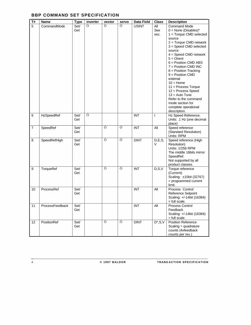
3.2 Transaction Specification TableT# Name Type inverter vector servo Data Field Class Description0 Null Set Ö Ö Ö NONE All No action.
This can be used to resetthe watchdog timer, or asa placeholder inconjunction with a globalExecuteBuffertransaction.
1 RunCmd Set/Get
Ö Ö Ö USINT All Network run / stopcommand.0 = Stop (refer to stopmode parameter)1 = Fwd2 = Rev3 = Bipolar*Actual motor direction isreturned inMotorDirection. In fwd orrev, only the absolutevalue of the commandreferences (speed,torque) are used. Inbipolar run, the signedreference values controlthe direction. Thesecommands are only validwhen CtrlSource =network control.
2 RunInhibit Set/Get
Ö Ö Ö BOOL All Commands a stopregardless of thecommand source(network, local orremote.)1 = Stop0 = No action*
3 CtrlSource Set/Get
Ö Ö Ö USINT All Source of actualRun/Stop command0 = Keypad (local)1 = Terminal strip(remote)2 = Control from network
4 ControlState Get Ö Ö USINT All 0 = Not Ready (no mainpower)1 = Ready (disabled)2 = Enabled3 = Stopping4 = Faulted
BBP COMMAND SET SPECIFICATION
© 1997 BALDOR TRANS ACTION SPECIF ICATION4
T# Name Type inverter vector servo Data Field Class Description5 CommandMode Set/
GetÖ Ö Ö USINT All
Seesec.
Command Mode0 = None (Disables)*1 = Torque CMD selectedsource2 = Torque CMD network3 = Speed CMD selectedsource4 = Speed CMD network5 = Orient6 = Position CMD ABS7 = Position CMD INC8 = Position Tracking9 = Position CMDexternal10 = Home11 = Process Torque12 = Process Speed13 = Auto TuneRefer to the commandmode section forcomplete operationaldescription.
6 HzSpeedRef Set/Get
Ö INT I Hz Speed Reference.Units: .1 Hz (one decimalplace)
7 SpeedRef Set/Get
Ö Ö INT All Speed reference(Standard Resolution)Units: RPM
8 SpeedRefHigh Set/Get
Ö Ö DINT D,E,S,V
Speed reference (HighResolution)Units: 1/256 RPMThe middle 16bits mirrorSpeedRef.Not supported by allproduct classes.
9 TorqueRef Set/Get
Ö Ö INT D,S,V Torque reference(Current)Scaling: ±15bit (32767)= programmed currentlimit.
10 ProcessRef Set/Get
INT All Process ControlReference SetpointScaling: +/-14bit (16384)= full scale.
11 ProcessFeedback Set/Get
INT All Process ControlFeedbackScaling: +/-14bit (16384)= full scale.
12 PositionRef Set/Get
Ö Ö DINT D*,S,V Position ReferenceScaling = quadraturecounts (4xfeedbackcounts per rev.)

BBP 1.02
TRANSACTION SPECIF ICATION © 1997 BALDOR 5
T# Name Type inverter vector servo Data Field Class Description13 PositionSpeed Set/
GetÖ Ö INT D*,S,V Positioning Speed
ReferenceMax speed used forpositioning commands.Also referred to as feedrate or target velocity.Units: RPM
14 PositionFeedFwd Set/Get
INT D*,S,V Position TrackingFeedforwardOptional commandedvelocity used to reduceerror in trackingcommand.
15 Position Set/Get
Ö Ö DINT D*,S,V Position counterScaling = quadraturecounts.
16 HomeOffset Set/Get
DINT D*,S,V Home position offsetThe captured homeposition plus the offsetequals the target position.
17 CurrentActual Get Ö Ö INT E,I,S,V
Actual motor phasecurrentUnits: 100mA RMSNote: calculated oninverter.
18 SpeedActual Get Ö Ö Ö INT All Actual motor speed(absolute value.)(Approximated in someproducts.)Units: RPM
19 FrequencyActual Get Ö Ö INT E,I,S,V
Actual motor frequencyUnits .1 Hz (one decimalplace)
20 PowerActual Get Ö Ö INT All Actual output powerUnits: Watts
21 InputVoltage Get INT All Input line voltageUnits: Volts RMS
22 OutputVoltage Get Ö Ö INT All Motor phase voltage(commanded)Units: Volts RMS
23 InternalValue Get Ö Ö C: USINTVariableIndexR: INTInternalValue
Seesec3.2.2
Request internal valueUsed for softwaredebugging. Not intendedfor customer use.
24 MotorDirection Get Ö Ö BOOL All 0 = Fwd1 = RevActual in positionfeedback products,commanded in others.
25 ZeroSpeed Get Ö Ö BOOL D,E,S,V
1 = At zero0 = Not at zero
26 AtSpeed Get Ö Ö BOOL All 1 = At commanded speed0 = Not at speed

BBP COMMAND SET SPECIFICATION
© 1997 BALDOR TRANS ACTION SPECIF ICATION6
T# Name Type inverter vector servo Data Field Class Description27 Warning Get BOOL All 1 = Warning
0 = No warnings present28 AtPosition Get Ö Ö BOOL D*,S,V 1 = At position
0 = Not at position29 AtSetpoint Get BOOL All 1 = At setpoint
0 = Not at setpoint30 AtSetSpeed Get Ö Ö BOOL All 1 = At set speed
0 = Not at set speed31 TerminalStrip Get Ö Ö WORD All Digital I/O status word
refer to specific sectionfor bit description.
32 SoftwareVersion Get Ö Ö STRING All Control software version(16 charactersmaximum.)
33 SoftwareRevision Get Ö Ö Ö UINT All Control software revisionnumber.For example S15-4.03 isreturned as 403.Note: for custom softwarerevisions only the core orstandard revision isreturned.
34 ProductSeries Get Ö Ö Ö UINT All Product SeriesFor example a Series15H returns: 15.
35 ProductClass Get Ö Ö Ö USINT All 5 = V, 0=H, 1=J36 OptionId1 Get Ö Ö USINT All Option ID1
0 = Not installed(See table)
37 OptionId2 Get Ö Ö USINT All Option ID20 = Not installed(See table)
38 RunTime Get Ö Ö UDINT All Total time power hasbeen applied.Units: seconds.
39 TableSelect Set/Get
Ö Ö USINT D,E,S,V
Parameter table selectRange 0 - 3Note: DDC only supports2 tables.Can only be changedwhen under networkcontrol.
40 AccDecGroup Set/Get
Ö Ö USINT All Accel / decel group selectRange 1 – 2Can only be changedwhen under networkcontrol.
41 WatchdogTime Set/Get
Ö Ö UINT All Network watchdog timerUnits: 10mS0 = disable20mS minimum60S (6000) maximumNote: resolution variesamong product classes.
BBP 1.02
TRANSACTION SPECIF ICATION © 1997 BALDOR 7
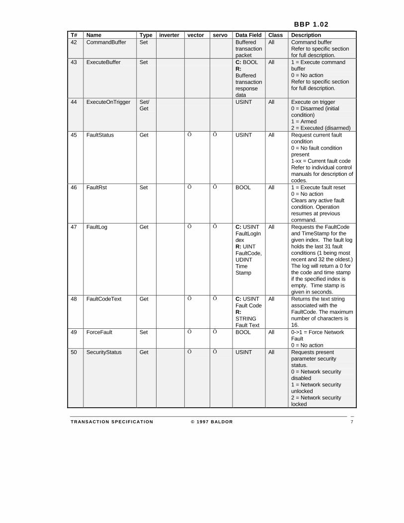
T# Name Type inverter vector servo Data Field Class Description42 CommandBuffer Set Buffered
transactionpacket
All Command bufferRefer to specific sectionfor full description.
43 ExecuteBuffer Set C: BOOLR:Bufferedtransactionresponsedata
All 1 = Execute commandbuffer0 = No actionRefer to specific sectionfor full description.
44 ExecuteOnTrigger Set/Get
USINT All Execute on trigger0 = Disarmed (initialcondition)1 = Armed2 = Executed (disarmed)
45 FaultStatus Get Ö Ö USINT All Request current faultcondition0 = No fault conditionpresent1-xx = Current fault codeRefer to individual controlmanuals for description ofcodes.
46 FaultRst Set Ö Ö BOOL All 1 = Execute fault reset0 = No actionClears any active faultcondition. Operationresumes at previouscommand.
47 FaultLog Get Ö Ö C: USINTFaultLogIndexR: UINTFaultCode,UDINTTimeStamp
All Requests the FaultCodeand TimeStamp for thegiven index. The fault logholds the last 31 faultconditions (1 being mostrecent and 32 the oldest.)The log will return a 0 forthe code and time stampif the specified index isempty. Time stamp isgiven in seconds.
48 FaultCodeText Get Ö Ö C: USINTFault CodeR:STRINGFault Text
All Returns the text stringassociated with theFaultCode. The maximumnumber of characters is16.
49 ForceFault Set Ö Ö BOOL All 0->1 = Force NetworkFault0 = No action
50 SecurityStatus Get Ö Ö USINT All Requests presentparameter securitystatus.0 = Network securitydisabled1 = Network securityunlocked2 = Network securitylocked

BBP COMMAND SET SPECIFICATION
© 1997 BALDOR TRANS ACTION SPECIF ICATION8
T# Name Type inverter vector servo Data Field Class Description51 SecurityLock Set Ö Ö INT or
NONEAll Unlocks or locks network
parameter security.Passing the validSecurityCode unlocksparameter access. Anyother value (includingNONE) locks parameteraccess.Note: valid only if networkor total security isenabled.
52 CalcPresets Set Ö Ö BOOL D,E,S,V
This transaction is usedduring setup to calculateinitial values for tuningand performanceparameters based onmotor nameplate values.Note: this command isnot valid for all productclasses.1 = Execute presetcalculation0 = No action
53 AutoTuneMode Set/Get
Ö Ö USINT D,E,S,V
0 = No test or cancelactive test(N>0) = Run test #N.(Refer to control manual)Note: CommandModemust be set to AutoTune.Not valid for all productclasses.
54 AutoTuneData Get INT D,E,S,V
Returns data related tothe active running test. Iftest has finished, the lastrecorded value will bereturned.
55 AutoTuneStatus Get Ö Ö USINT D,E,S,V
Returns result ofpreviously executed test.0 = Test failed1 = Test Passed2 = Test currently running
56 BlockStructure Get Ö Ö Ö USINTLevel1Max,Level2Max,Level3Max
All Returns the number ofblocks on eachprogramming level.Assumes a max of threeprogramming levels.
57 BlockDetail Get Ö Ö Ö C: USINTLevel,BlockR: USINTMaxParams, STRINGBlockName
All Returns the number ofparameters in the blockand the BlockName (16characters max.)

BBP 1.02
TRANSACTION SPECIF ICATION © 1997 BALDOR 9
T# Name Type inverter vector servo Data Field Class Description58 BlockParamDetail Get Ö Ö Ö C: USINT
Level,Block,IndexR: INTPnum,Pvalue,Pmin,Pmax,Pdlft,Pprec,Ptype,STRINGPname,Punits
All Returns full parameterdetail information for theparameter specified atthe given Level, Blockand Index.
59 ParameterDetail Get Ö Ö Ö C: INTPnumR: INTPnum,Pvalue,Pmin,Pmax,Pdlft,Pprec,Ptype,STRINGPname,Punits
All Returns full parameterdetail information for thegiven Pnum.
60 ParameterList Get Ö Ö C: INTPnum,ListIndexR:STRINGListText
All Returns the enumeratedlist string for the givenparameter number andlist index. Max number ofcharacters is 16. IfListIndex exceeds thenumber of elements an‘end of block’ status willbe returned. (Note:Pmax should be used todetermine the end of thelist.)
61 ParameterValue Set/Get
Ö Ö Ö C: INTPnum ,PvalueR: INTPvalue(ExcludingPvaluefrom CMDindicatesRequestonly.)
All Change / request value ofspecified user parameter.Returned value will giveactual, after any boundschecking. Refer toindividual control manualfor detailed parameterdescription.

BBP COMMAND SET SPECIFICATION
© 1997 BALDOR TRANS ACTION SPECIF ICATION10
T# Name Type inverter vector servo Data Field Class Description62 BatchSend Get Ö Ö C: Int
GroupNumberR: INTPnumN,PvalueN,… N=16
All Batch transfer thatreturns raw parameters(data only) from control tohost. Up to 16parameters are sent at atime. Last group will betruncated if necessary.Group numbers startfrom 0. If theGroupNumber exceedsthe number of blocks an‘end of block’ status willbe returned.The control must bedisabled.
63 BatchRcv Set Ö Ö INTPnumN,PvalueN,… N=16
All Block transfer thataccepts raw parameter(data only) from host tocontrol. Up to 16parameters may be sentat a time. Parametersmay be sent in any order.The control must bedisabled.
64 FactorySettings Set Ö Ö BOOL All 1 = Reset all parametersto initial (factory)condition.0 = No action
65 StatusStructure Get Ö Ö SINTStatusMax,DiagsMax,OtherMax
All Returns number ofscreens in each statuslevel.
66 StatusDetail Get Ö Ö C: SINTLevel,IndexR: UINTType.(if Type =standard)INT Value,UINTPrec,STRINGName,Units(If Type =custom)STRINGLine1,Line2
All Type = 1 for standard(keypad overlaysSTOP,FWD,REV andLOCAL, REMOTE etc.)Type = 2 for Custom:drive formats and sendsboth lines of text. Notes:Level 1, Index 0 returnsthe startup screen(custom type.) Level 3,Index 0 gives the level 3menu text.
67 StatusValue Get Ö Ö C: SINTLevel,IndexR: INTValue
All Returns the current valuefor the specified screen.Note only valid if screenis type: Standard, elsereturns invalid data lengtherror.

BBP 1.02
TRANSACTION SPECIF ICATION © 1997 BALDOR 11
T# Name Type inverter vector servo Data Field Class Description68 KeypadData Get/
SetÖ Ö C: UINT
KeyValueR:Harmonized keypadcontrol andtext data
All Changes the current keystatus. When a key isreleased a NO_KEY issent from the keypad.KeyValue codes conformto the standardharmonized keypadprotocol.Returns buffered displaydata. The standardharmonized keypadprotocol is embedded in aBBP packet.Note: the Watchdogfeature should be usedwith keypad controldevices for safety.
69 ClearAll Set Ö Ö USINT All Reserved for factory use.70 LogClear Set Ö Ö USINT All Reserved for factory use.71 AnalogInput1 Get Ö Ö UINT All72 AnalogInput2 Get UINT All
Reads the raw value ofthe A/D converters on thecontrol. Update rate andresolution vary percontrol. Unused MSBswill be padded with zero.
73 SetAnalogOut1 Set/Get
Ö Ö INT All
74 SetAnalogOut2 Set/Get
Ö Ö INT All
Commands the DACs onthe control, and / oroption card. Analogoutput parameter must beset to Serial to be valid.(Note 8 bit DACs will onlyuse the upper byte.)
75 SetDigitalOut Set Ö Ö BYTE All Commands the digitaloutputs on the control,and / or option card. Onlylowest four bits are used.The LSB corresponds toopto out #1. The optooutput parameter must beset to serial to be valid.
76 GetDebugVal Get Ö Ö C: IntMemLocR: INTValue
All Reserved for factory use.
77 ControlRating Get Ö C:INTR:INT
All Returns Cont Current,Current Scaling, DefaultMotor Volts & PowerBase ID.
78 FeedbackType Get Ö C:UsintR:Usint
All Returns 0 if no feedbackmodule is installed, 1 ifresolver board is installed& 2 if encoder board isinstalled.
250 ExtTrans1 ---- USINTExtTrans,DATAFIELD
All Reserved for future use.

BBP COMMAND SET SPECIFICATION
© 1997 BALDOR TRANS ACTION SPECIF ICATION12
T# Name Type inverter vector servo Data Field Class Description251 ExtTrans2 ---- USINT
ExtTrans,DATAFIELD
All Reserved for future use.
252 ExtTrans3 ---- USINTExtTrans,DATAFIELD
All Reserved for future use.
253 ExtTrans4 ---- USINTExtTrans,DATAFIELD
All Reserved for future use.
254 ExtTrans5 ---- USINTExtTrans,DATAFIELD
All Reserved for future use.
255 ExtTrans6 ---- USINTExtTrans,DATAFIELD
All Reserved for future use.
Note: items shown in strikethrough are proposed for future versions of the protocol.They are not implemented in this version.
3.2.1 5 - CommandMode
Command
5 USINT CommandMode
Response
5 ST USINT ComandMode
Type: Set/GetThis transaction is used to change the control’s command mode. The command modeis an 8-bit value that changes the control mode of operation. Loading the appropriatevalue into the command mode register activates the appropriate operating mode. Onlyone mode can be selected at a time. The following is a description of the possiblecommand modes:
3.2.1.1 Command Mode Table
Value Mode Class Description
0 None All No mode selected. Output stage of control remainsoff or disabled (voltage and current removed from themotor), regardless of RunCmd condition.
1 Torque CMD selected source D,S,V Closes the current loop with command input from thesource selected in the COMMAND SELECTparameter.
2 Torque CMD network D,S,V Closes the current loop with command input from theTorqueRef register.

BBP 1.02
TRANSACTION SPECIF ICATION © 1997 BALDOR 13
Value Mode Class Description
3 Speed CMD selected source All Closes the velocity loop with command input from thesource selected in the COMMAND SELECTparameter.
4 Speed CMD network All Closes the velocity loop with command input from theSpeedRef register.
5 Orient D*,S,V C or Index channel orient. The motor will becommanded in the Fwd direction at the predefinedhoming speed until the index pulse is detected. Themotor will then be commanded to hold position at thepredefined home offset
6 Position CMD ABS D*,S,V Closes the position loop with an absolute positioncommand from the PositionRef register.
7 Position CMD INC D*,S,V Closes the position loop with an incremental positioncommand from the PositionRef register
8 Position Tracking D*,S,V Closes the position loop in position vs time trackingmode with command input from the PositionRefregister. Optional feedforward from PositionSpeed.Future Implementation
9 Position CMD external D*,S,V Closes the position loop with command input fromexternal option source (such as pulse follower exbcard.)
10 Home D*,S,V Executes a position mode home.
Future Implementation
11 Process Torque All Closes the torque process control loop. Commandscome from the appropriate command inputparameters.
12 Process Velocity All Closes the velocity process control loop. Commandscome from the appropriate command inputparameters.
13 Auto Tune D,E,S,V
Changes command mode to Auto Tune. Testconditions are controlled by AutoTuneMode.
Default Condition
The command word is defaulted to 00H on power-up. This indicates a disabledcondition.
3.2.2 23 – InternalValue (Not intended for customer use )
Command23 USINT VariableIndex
Response23 ST INT InternalValue

BBP COMMAND SET SPECIFICATION
© 1997 BALDOR TRANS ACTION SPECIF ICATION14
Type: Get
This transaction returns the selected internal variable value.

BBP 1.02
TRANSACTION SPECIF ICATION © 1997 BALDOR 15
3.2.2.1 Variable Index Table (TBD)# Name Scale Precision Description Class
0 ANA INPUT #1 ALL
1 ANA INPUT #2 ALL
2 ANA OUTPUT #1 ALL
3 ANA OUTPUT #2 ALL
ELEC ANGLE V,S
ABS COMMAND ALL
PWM VOLTAGE V,S,SV,O
DIRECT CURRENT
CMD DIRECT CUR
QUAD CURRENT
CMD QUAD CUR
FIELD WEAKEN
FOLLOWING ERR
QUAD CONTROL
DIRECT CONTROL
AC VOLTAGE
BUS VOLTAGE
VECTOR ANGLE
POWER
OVERLOAD ACCUM
PH1 CURRENT
PH2 CURRENT
PH3 CURRENT
DELTA COUNT
% RATED LOAD
USER OUTPUT
CONTROL TEMP
BASE ID CODE
CONT CUR
PEAK CUR
PWM FREQ
AMPS / VOLT SCALE
RATED VOLTAGE
OUTPUT ZONE
This table is to be defined in a future version of the specification.

BBP COMMAND SET SPECIFICATION
© 1997 BALDOR TRANS ACTION SPECIF ICATION16
3.2.3 30 - TerminalStrip
Command31
Response31 ST WORD TerminalStrip
Type: Get
This transaction returns a bit-wise word representing the status of the control digitalinputs and outputs.
BIT NAME Typical Single-Axis Location Typical Multi-Axis Location
15 Not used
14 Not used
13 Not used
12 Enable J1/J4 - 8 J1B - 1
11 Forward J1/J4 - 9 J1B - 2
10 Reverse J1/J4 - 10 J1B - 3
9 Input 1 J1/J4 - 11 J1B - 4
8 Input 2 J1/J4 - 12 J1B - 5
7 Input 3 J1/J4 - 13 J1B - 6
6 Input 4 J1/J4 - 14 J1B - 7
5 Input 5 J1/J4 - 15 J1B - 8
4 Input 6 J1/J4 - 16 J1B - 9
3 Output 1 J1/J4 - 19 J1B - 10
2 Output 2 J1/J4 - 20 J1B - 11
1 Output 3 J1/J4 - 21 J1B - 12
0 Output 4 J1/J4 - 22 J1B - 13
A bit value of 1 indicates closed or on, 0 = open or off.
3.2.4 36 - 37 – OptionId#
Command36
Response36 ST USINT OptionId

BBP 1.02
TRANSACTION SPECIF ICATION © 1997 BALDOR 17
Type: Get
This transaction returns the id number for the option installed in the specified location.
ID Option No Option Name Group
1 EXB001A01 RS232 SERIAL 2
2 EXB002A01 RS422/485 SERIAL 2
3 EXB003A01 ISOLATED INPUT 1
4 EXB004A01 4 OUT RELAY / 3-15 PSI 2
5 EXB005A01 PULSE FOLLOWER 1
6 EXB006A01 DC TACH 1
7 EXB007A01 HIGH RES ANALOG 2
8 EXB010A01 ANALOG OUT / 3 OUT RELAY 2
9 EB00??A00 MACRO COMMUNICTIONS 2
10 EB0095A00 HIGH SPEED COMMUNICATIONS RS232 / 485 2
70 EXB013A01 Devicenet 2
Group 1 is a lower board, group 2 is upper.
3.2.5 41 - WatchdogTime
Command41 UINT WatchdogTime
Response41 ST UINT WatchdogTime
Type: Set/Get
Scale / Units: 10mS
This transaction is used to change the value of the network watchdog timer. The valueis entered in milliseconds (mS). The watchdog timer is used to detect acommunications loss. When the time between network commands exceeds the valuestored in this register, the control faults and disables the motor. Each time a networkcommand is received the internal timer is reset to zero. The host must continuouslysend commands to keep the timer reset. If desired a NULL transaction can be used toreset the timer. Setting the timer to zero disables this function. The minimum timevalue (other than zero) is 20mS (2). The maximum value is 60S (6000). Resolutionvaries among product classes.

BBP COMMAND SET SPECIFICATION
© 1997 BALDOR TRANS ACTION SPECIF ICATION18
3.2.6 42 - CommandBuffer
Command42 Buffered transaction number Buffered data up to 63 bytes
Response42 ST
Type: Set
This transaction is used to buffer a command for later execution. This is useful forsynchronizing commands to multiple controls. The command buffers of each controlare sequentially loaded with the desired command. An ExecuteBuffer command isthen given globally to all controls.
NOTE: Request transactions should not be used in conjunction with a global executeas responses are not sent to global commands.
NOTE: A NULL transaction may be stored in the buffer to keep an individual control from responding to a global execute command.
3.2.7 43 - ExecuteBuffer
Command43
Response43 ST Buffered transaction response
Type: Set
This transaction executes the data stored in the command buffer as if it was justreceived from the host. The response will be the execute command buffer transactionnumber followed by the buffered command normal response. This is useful forsynchronizing commands to multiple controls (with a global address.) (Note: if a globaladdress is used no response will be given by the buffered command.
3.2.8 44 - Execute On Trigger
Command44 UINT TriggerStatus
Response44 ST UINT TriggerStatus

BBP 1.02
TRANSACTION SPECIF ICATION © 1997 BALDOR 19
Type: Set/Get
This transaction arms or disarms a “Wait Until Trigger” function. When armed thecontrol will execute the data stored in the command buffer when it receives andexternal terminal strip signal. This is useful for synchronizing commands with anexternal event.
This command can change the status between disarmed and armed. This can beuseful for backing out of a trigger command before an external signal is given. Oncethe trigger signal is given and the buffer command is executed, the trigger statuschanges to ‘executed’ and the trigger is disarmed. The trigger must be rearmed beforeanother trigger event can occur.
0 = Trigger disarmed (initial condition).
1 = Trigger armed, awaiting external signal.
2 = Trigger executed. (This is a disarmed condition.)
3.2.9 ParameterDetails
Below is a description of the data that is return during a parameter detail response:
INT PMin Parameter minimum allowed value.INT PMax Parameter maximum allowed value.
(Number of list items in anenumerated type parameter.)
INT Pdflt Parameter default value (factory)value.
USINT Pprec Indicates the number of decimalplaces to use for the parameter value.
BYTE Ptype Returns bit-wise parameter type.Bit 0 = Numeric parameterBit 1 = Enumerated list parameterBit 2 = Can be changed while enabledBit 3 = Default from calculationBit 4 = Not set during ‘restore tofactory’Bit 5 = Signed parameter
STRING Pname Returns string representing parametername. For example “Preset Speed#1”. Max number of characters is 16.
STRING Punits Returns the parameter engineeringunits string. Max number ofcharacters is 4.


BBP 1.02
REVISION TABLE © 1 9 9 7 BALDOR 1
4 SPECIFICATION REVISION TABLESPECREVISION
DOCUMENTREVISION
PUBLISHEDDATE
DESCRIPTION
BBP 1.X XA 3/?/96 Initial proposal stage.
BBP 1.X XB 5/14/96 Additional proposals
BBP 1.XB XB 5/16/96 Re-structured Data-link layer. Added length fields to both layers.Removed DLE sequences. Added support for sub-masteraddressing (future implementation.) Added immediate Data Linkacknowledgments. Changed terminology: Application Layer becamepresentation layer. Data link layer packets are ‘telegrams’, totalpresentation portion of telegram is the ‘message’. Individualpresentation units are ‘transactions’.
BBP 1.XC XC 5/22/96 Changed Data Link layer back to ANSI style (with DLE sequences),(no length fields in either layer.) Use ANSI style select and pollmessages. (This means all reads are delayed.) A total of 3 Data Linktelegrams will be used: polling, command, and response. Changedlayer terminology back to Application Layer again (it is morestandard.) Restructured application transactions to return statuscode along with transaction number.
BBP 1.XD XD 6/4/96 Adding the ability to retransmit responses from the slave. Removedduplicate addresses and DLE NAKs. Using a timeout only schemefor lost or invalid messages.
BBP 1.XE XE 6/7/96 Adjusting the time-out specs.
BBP 1.XF XF 6/10/96 Adjusting the time-out specs / CRC etc.
BBP 1.XG XG 7/21/96 Misc Clean-up.
BBP 1.XH XH 8/19/96 Changed CRC to CCITT. Misc.
BBP 1.XI XI 8/27/96 Changed address range to 1-31. Added support for bit-wise addressselection of global or point-to-point. Added bit-wise address selectionand support for BCC. Changed time-out delay to BOOL (off or 1.5character times.) Added Data type section to application layer.Completely restructured the transaction specification section.Removed transaction quick list.
BBP 1.XJ XJ 9/12/96 Misc. typographical corrections. Updated slave flowchart. AddedPositionFeedFwd. Moved ClearAll. Added LogClear. Renumberedtransactions.
BBP1.XK XK 2/25/97,7/24/97
Changed TorqueRef scaling to 15bit = current limit. Misc notes andtext changes for clarity. Added HzSpeedRef for inverters.Restructured parameter access transactions – removed many.Renamed block send and receive to BatchSend and BatchRcv.Combined the ‘backwards compatible’ keypad transactions into asingle one. Added 3 transactions for re-creating keypad statusscreens in a smart keypad. Reserved 250 - 255 for future 'extended'transactions.
BBP1.00 - 9/3/97 First official version.

BBP COMMAND SET SPECIFICATION
© 1997 BALDOR REVIS ION TABLE2
SPECREVISION
DOCUMENTREVISION
PUBLISHEDDATE
DESCRIPTION
BBP1.01 - 11/17/1997 Split data link layer and command set into separate documents toease maintenance. Updated Transaction list to add MME requiredtransactions 71 - 75. Removed the following transactions from thecurrently supported list: PositioniFeedFwd, HomeOffset,CommandBuffer, ExecuteBuffer, ExecuteOnTrigger, AutoTuneMode,AutoTuneData, AutoTuneStatus, BatchSend
BBP 1.01 A 12/9/97 Added BatchSend back to the supported list. Added GetDebugVal tolist.
BBP 1.01 B 1/4/98 Added document information and copyright notices.
BBP 1.02 C 1/14/99 Corrected page numbers, added transaction numbers 77 & 78.Changed transaction 73 & 74 to a Set/Get. Removed strikethroughand added three columns to show which transactions are supportedby what drives.
BBP 1.03 D 2/15/99 Changed S15 to inverter, S18 to vector & mint to servo on columnheaders.


