mmmmhhi - dtic.mil · A microfilled composite veneering resin, Isosit, was processed to the four...
96
RD-A1" 682 THE BOND S 'TRENGTH OF COMPOSITE RESIN TO DENTAL CRSTING v/1 ALLOYS USING AN EL..(U) AIR FORCE INST OF TECH HRIGHT-PATTERSON AFE OH K S SMITH JUN 9 UNCLASSIFIED AFIT/CI/NR-S5-1i9T F/G 11/6 N mmmmhhi
Transcript of mmmmhhi - dtic.mil · A microfilled composite veneering resin, Isosit, was processed to the four...

RD-A1" 682 THE BOND S 'TRENGTH OF COMPOSITE RESIN TO DENTAL CRSTING v/1ALLOYS USING AN EL..(U) AIR FORCE INST OF TECHHRIGHT-PATTERSON AFE OH K S SMITH JUN 9
UNCLASSIFIED AFIT/CI/NR-S5-1i9T F/G 11/6 N
mmmmhhi

t
.
NI _
.IIII~u. 12 .6
-. MICROCOPY RESOLUTION TEST CHART
o ATIAL URU OF STADAR0S -9-A
iIIB *n 33
34 2
11111.1111 *1
.5
.5
-. o

11NCJASS __h __. I.* .ljrd -.-.. - .-- . .SECURITY Ct AS$IFICATION Or 7 04S OIAfi (10. ~..~~pd
REPORT DOCUMENTATION PAGE RI- ADINTHUCITI0N%
REPORT NUMUE.R 3GVT ACCESSION 40. 1. RECIPIENT*$ CAT ALOG~ HUNML
C4 AFIT/Cl/flR 85.-119T00 8. TIT LE (and Suable##) S. TYPE OF RELPORT & PERIOD COVERED
(0 The Bond Strength of Cai~osite Resin to Deta THESIS/0I'I9AMMONCasting Alloys Using an Electro-Chernical Tin ____________
0 Plating Systan G. PERFORMING oGOG. REPORT 04UNDER
VOG 7. SU"R~). CONTRACT 00 GRANT NUMBER(S)
Keith S. Smith, II
9. PERFORMING ORGANIZATION NAME AND ADDRESS 10. PROGRAM ELEMFNT. PROJECr. TASKAREA I WORK UNIT NUMBERS
AFIT STUDENT AT: The University of Texams
iI. CONTROLLING OFFICE NAME AND ADDRESS 12. REPORT DATE
AFIT/NR June~ 1985WPAFB OH 45433 - 6583 IS. NUMBER OF PAGES
6414. MONITORING AGENCY NAME 4 ADDRESS(11 digI.,.eI from ConiseOingu Office) IS. SECURITY CLASS. (of this report)
UNCLASSIS.. DECLASSIFICATOee/OOWNGRADINeG
SCHEDULE
1.DISTRIBUTION STATE14ENT (of this Roport) ?L T CAPPROVED FOR PUBLIC RELEASE; DISTRIBUTION UNLIMITED E E T
OCT 3 0 1985
17. DISTAIBUTION STATEMENT (of the abstract Onfored In block 30, It different frm Raoed)
B.
IS. SUPPLEMENTARY NOTES
APPROVED FOR PUBLIC RELEASE: JAW AFR 190-1 Dean fE ReAearc ad
I'ajty- Professional OevelopnAFIT. Wright-Patterson A
St. KEY WORPS (Continue on *ever** side if necessary and Idervliy by block Aumbou)
LU 20. ADSSTRACT (Continue on Poerse, side it noceGeary and Identify' by block number)&mj
ATTACHED
DD I "JA,"13 1473 EDITION OF I NOV GS IS OBSOLETE UNCLASSSECURITY CLASSIFICATION4 OF THIS PAGE (Whn o flS,
%
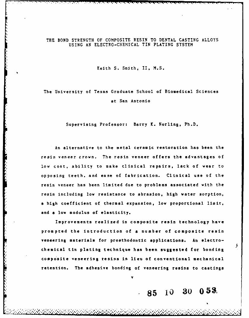
THE BOND STRENGTH OF COMPOSITE RESIN TO DENTAL CASTING ALLOYS
USING AN ELECTRO-CHEMICAL TIN PLATING SYSTEM
Keith S. Smith, II, M.S.
The University of Texas Graduate School of Biomedical Sciences
at San Antonio
Supervising Professor: Barry K. Norling, Ph.D.
An alternative to the metal ceramic restoration has been the
resin veneer crown. The resin veneer offers the advantages of
low cost, ability to make clinical repairs, lack of wear to
opposing teeth, and ease of fabrication. Clinical use of the
resin veneer has been limited due to problems associated with the
resin including low resistance to abrasion, high water sorption,
a high coefficient of thermal expansion, low proportional limit,
and a low modulus of elasticity.
Improvements realized in composite resin technology have
prompted the introduction of a number of composite resin
veneering materials for prosthodontic applications. An electro-
chemical tin plating technique has been suggested for bonding
compo'site veneering resins in lieu of conventional mechanical
retention. The adhesive bonding of veneering resins to castings
v
85 30 oa

;.. would prove beneficial by improving esthetics and eliminating the
percolation of fluids at the resin-metal interface.
The purpose of this investigation was to examine the shear
bond strength of a composite resin processed to gold and base
metal specimens that were treated with an electro-chemical tin
plating technique. Uniform specimens were cast in a gold alloy
and a base metal. Conventional retentive beads on the gold alloy
and electroetching of the base metal served as controls in this
investigation. &-
A microfilled composite veneering resin, Isosit, was
processed to the four experimental groups which were stored for 7
days at 370 C. Following thermal cycling between 5C and 60 0 C,
shear bond strengths were determined using an nstron testing
machine.
The resulting resin shear bond strengths of the electro-
chemical tin plating technique with the gold and base metal
specimens were significantly lower than those obtained with
retentive beads or electroetching. The opaque layer of the
electro-chemical tin plating technique was found intact on the
metal specimens following shear bond testing. This would suggest
that inadequate bonding occurred between the opaque layer and the
Isosit resin. Therefore, the actual bond strength of the
electro-chemical tin plating technique was not determined. A
significant improvement in bond strength was found in a
subsequent pilot study when Isosit fluid, a component of the
vi
.° .: j . . *.*
. . .. .. .. . . .

Isosit system containing a cross-linking agent, vas placed over
the opaque layer prior to processing.
vii

* . ... , .. • . .- ... -. *--..-, . -. ~..,.. - .- ..- .- - --
11-9TAFIT RESEARCH ASSESSMENT
The purpose of this questionnaire is to ascertain the value and/or contribution of research[ accomplished by students or faculty of the Air Force Institute of Technology (AU). It would be*. greatly appreciated if you would complete the following questionnaire and return it to:
AFIT/NRWright-Patterson AFB OH 45433
RESEARCH TITLE: The Bond Strength of Composite Resin to Dental Casting Alloys Using
an Electro-Chemical Tin Plating System
* AUTHOR: Keith S. Smith, II
RESEARCH ASSESSMENT QUESTIONS:
- 1. Did this research contribute to a current Air Force project?
( ) a. YES ( ) b. NO
2. Do you believe this research topic is significant enough that it would have been researched(or contracted) by your organization or another agency if AFIT had not?,
( ) a. YES ( ) b. NO
3. The benefits of AFIT research can often be expressed by the equivalent value that youragency achieved/received by virtue of AFIT performing the research. Can you estimate what thisresearch would have cost if it had been accomplished under contract or if it had been done in-housein terms of manpower and/or dollars?
a. MAN-YEARS ( ) b. $4. Often it is not possible to attach equivalent dollar values to research, although the
results of the research may, in fact, be important. Whether or not you were able to establish an* equivalent value for this research (3. above), what is your estimate of its significance?
a. HIGHLY ( ) b. SIGNIFICANT ( ) c. SLIGHTLY ( ) d. OF NOSIGNIFICANT SIGNIFICANT SIGNIFICANCE
5. AFIT welcomes any further comments you may have on the above questions, or any additionaldetails concerning the current application, future potential, or other value of this research.Please use the bottom part of this questionnaire for your statement(s).
NA4E GRADE POSITION
. ORGANIZATION LOCAT'ION
- STATEMENT(s):
I. .~ . .* . .. . . . . . . * . . .. . V .

/
THE BOND STRENGTH OF COMPOSITE RESIN TO DENTAL CASTING ALLOYS
USING AN ELECTRO-CHEMICAL TIN PLATING SYSTEM
A
THESIS
Presented to the Faculty of
The University of Texas Graduate School of Biomedical Sciences
at San Antonio
in Partial Fulfillment
of the Requirements
for the Degree of
Master of Science
By
Keith S. Smith, II, D.D.S.
San Antonio, Texas
June, 1985
......................
A': * * .. . -

DEDICATION
I wish to dedicate this document, and the effort it
represents, to four people who fostered my personal and
professional development.
My parents, Keith S. and Vivian M. Smith, have sacrificed,
guided, tolerated, taught, financed and inspired me tirelessly
for many years. It's time I said thank you.
John D. Adams, D.D.S., Professor and Chairman, Department of
Fixed Prosthodontics, (Retired) West Virginia University School
of Dentistry, Morgantown, West Virginia taught me patience,
professionalism, dedication and a love of Prosthodontics.
Leah Grishkat, my wife, endured the turmoil a residency
creates and remained an inspiration and my best friend
throughout.
ii
- . .o

ACKNOWLEDGEMENTS
I wish to thank Dr. Barry K. Norling (Associate Professor
and Head, Division of Biomaterials) for sharing his reasearch
design and methodology experience, for opening his laboratory to
me and giving freely of his valuable time.
Dr. E. Steven Duke (Chairman, Dental Materials, ViI!oid I ll
USAF Medical Center) was the driving force behind this project
and spent countless hours planning, word processing and editing.
I owe many thanks to Dr. Thomas L. Huff (Chairman,
Prosthodontics, Wilford Hall USAF Medical Center) who has taught
me Prosthodontics and has been a constant source of
encouragement.
Special appreciation is extended to Dr. Kenneth D. Rudd
(Associate Dean for Dental Continuing Education) and Dr. James A.
Fowler Jr. (Assistant Professor, and Assistant Head, Division of
Postdoctoral Prosthodontics) for serving on my graduate
committee. Their suggestions and editorial contributions were
extremely helpful during this project.
Additional appreciation is extended to Mr. Ruben G. Urrutia
for his assistance with sample preparation.
iv

TABLE OF CONTENTS
Page
Title ............. ****.............
Approval .............. *..........i
Dedication .......... **** ...... *.*ii,.
Acknowledgements ..... . **...... ...... .iv
A bstract .......... . ..................................
Table of Contents ..................... viii
List of Tables ........................ *** x
I. INTRODUCTION a..............*.......*..*.. 1
II. LITERATURE REVIEW ......... *.....*....* *.. 6
A. Porcelain Restorations .............. 6
B. Acrylic Resin Veneered Restorations ....... 10
C. Composite Resins ................. 12
D. Electrolytic Etching of Alloys .......... 16
III. RESEARCH OBJECTIVES . ... .. .. .. . .. ... . .. .. . .... .. .. . .. 20
IV. MATERIALS AND METHODS . .. ... .. .. . .. . ... . . . ... eas . . . . 21
A.* Overview a ..... e.... ................. 21
B. Metal Specimen Preparation ............ 21
C. Resin Veneering ......... *......... 29
D.* Shear Bond Testing .. *.4.*.............. 34
E. Statistical Analysis *..............40
V.* RESULTS ....................... 41
VI. DISCUSSION a . . ... .. .. .. .. . .**** .. .. 45
viii
Page
* ~Appendix *.......** *~ * * *~ * * *..*.* * 5
V iteatr Cited..... ........................................ 55
ix

LIST OF TABLES
Page
Table 1. Statistical Means and Standard Deviationsof Composite Shear Bond Strength .............. 42
Table 2. Summary Table for One-Way Analysis ofVariance Comparing Retentive System Groups .... 44
Table 3. Shear Bond Strengths of Isosit to Gold AlloyWhen Isosit Fluid was Used .................... 48
1x
iK
S.

LIST OF FIGURES
Page
Figure 1. Plastic Patterns with Micro-Retention Beads . 23
Figure 2. Sprued Plastic Patterns ...................... 24
Figure 3. Completed Castings Removed from Investment ... 26
Figure 4. Spot Welded Castings to Stainless Steel Wirefor Electroetching ......... .. ....... . 27
Figure 5. Electroetching in 10% Sulfuric Acid .......... 28
Figure 6. Castings Prior to Electroetching, FollowingElectroetching, and After Cleaning in 10%Hydrochloric Acid ...... 30
Figure 7. Tin Plating of Gold Casting With OVS System .. 31
Figure 8. Appearance of Tin Plated Gold Casting ........ 32
Figure 9. Confirmation of Oxidation by LightenedAlloy Surface ........ 0..*.. . ..... .... ... 33
Figure 10. Application of Opaque-Adhesive to Castings ... 35
Figure 11. Application of Two Layers of Opaque-AdhesiveContaining Opaque Powder ..................... 36
Figure 12. Isosit Resin Condensed into Teflon Tubes ..... 37
Figure 13. Device Used to Hold Specimens During ShearBond Tests ................... .............. . 38
Figure 14. Loading of Specimens in the Instron TestingMachine With Beveled Blade ................... 39
Figure 15. Shear Bond Strength Results GraphicallyRepresented .................................. 43
Figure 16. Example of Specimen Failure at the Resin-Opaque Interface ............................. 47
Figure 17. Example of Specimen Failure at the Opaque-Metal Interface When Isosit Fluid was Used ... 49
xi

I. INTRODUCTION
Esthetic demands have been an important consideration in the
evolution of materials used in restorative and prosthetic
dentistry. An esthetic restorative material complemented with
the required physical properties and recognized as an ideal
replacement for tooth structure has yet to be developed.
(Phillips, 1982)
The natural "tooth like" appearance of dental porcelain has
led to its widespread use in restoring severely compromised
teeth. (Craig, 1980; McLean, 1980) In addition to its esthetic
qualities, properties such as long term color stability, a
resistance to absorption of fluids, excellent gingival response,
and a high wear resistance have equally contributed to the
popularity of porcelain use. (Phillips, 1982) Porcelain is often
reported to have a high compressive strength in relation to its
inferior tensile strength. (Craig, 1980, Phillips, 1982)
Overcoming this deficiency requires a strict adherence to
preparation design to direct resulting forces in a favorable
pattern and provide a sufficient bulk of porcelain in the final
restoration. (Preston, 1977; McLean, 1980)
An improvement in the clinical performance of porcelain was
accomplished with the introduction of a metal substructure. With
a metal substructure, preparation design was simplified and a
more flexible clinical application was realized. (Dykema et al.,
1958; Mumford, 1965) The resulting metal ceramic restoration
": 1
%* ° ., . . . . . . . . . . . . .
. . . . . . . . . . . . . . . . . .

2
has become the standard of care when fabricating esthetic
complete crowns. (McLean, 1983)
The desirable property of wear resistance of dental
porcelain can become a disadvantage and jeopardize the clinical
success. Severe wear of opposing teeth or restorative materials
has been reported when porcelain is placed in occlusion.
(Mahalick et al., 1971; Monasky and Taylor, 1971) An additional
disadvantage of using porcelain as a restorative material is
encountered when porcelain fractures. The clinical repair of
porcelain surfaces has been extremely difficult to accomplish and
has met with little success. (Welsh and Schwab, 1977; Dent, 1979;
Highton et al., 1979)
An alternative to the metal ceramic restoration has been the
acrylic resin veneer crown. Beginning with its introduction in
1940, it gained widespread popularity due to simplicity of
fabrication, ease of clinical repairs, lack of wear to opposing
teeth, and relatively low initial cost. (Dykema et al., 1958;
Peyton and Craig, 1963) Unfortunatley, a number of deficiencies
have been reported with acrylic resin veneer crowns to limit
their clinical application.
The low proportional limit and modulus of elasticity of
acrylic resins may lead to excessive plastic deformation when
placed under the stresses encounted in prosthetic applications.
(Peyton and Craig, 1963) The lack of adhesion and considerable
differential thermal expansion and contraction between the resin
material and the metal substructure results in percolation of
oral fluids and may contribute to early discoloration of the
~ V ~ .% ' -. '. %~*** ~**~*** ~ ~**. * * ** .

restoration. (Phillips, 1982) A low resistance to toothbrush
abrasion, high water sorption, porosity, and compromised esthetic
results are additional deficiencies reported with this
combination of materials. (Peyton and Craig, 1963; Tylman, 1970;
Phillips, 1982) The requirement of developing mechanical
retention for the resin veneer has also been criticized. (Tanaka
et ai., 1978; Tanaka et al., 1979)
The introduction of inorganic filler particles into a newly
developed dimethacrylate resin base formulation gave birth to a
new generation of direct resin restorative materials in the
1960's. (Bowen, 1962; Phillips, 1982) These so called,
"composite resin" filling materials were found to have improved
wear characteristics, including lower coefficients of thermal
expansion, better color stability, less water scrption, and less
polymerization shrinkage. (Peterson et al., 1966; Nuckles and
Crosby, 1972) While these new composites have had little
application in prosthetic dentistry, other than porcelain repair
procedures (Dent, 1979), further modification in the late 1970's
gave rise to a new class of potential crown and bridge veneerinxg
resin materials. (Raptis et al., 1979; Rupp, 1979)
This new class of resin material incorporates an extremely
small filler particle consisting of pyrolytic or precipitated
silica. (Phillips, 1982) Clinical research has demonstrated an
improvement in surface smoothness with these "microfilled resins"i
over the larger glass filled composite resins. (Jorgensen and
Asmussen, 1978; Mitchem and Gronas, 1982)

4
These advancements in composite resin technology have
prompted the introduction of several new crown and bridge resin
veneering materials. Initial laboratory studies have shown an
improvement in physical properties with these materials when
compared to conventional acrylic veneering resins. (Nathanson t :
al., 1985; Osorio et al., 1985) The clinical behavior of these
new materials, as assessed by long term clinical study, has yet
to be determined.
Bertolotti and Napolitano (1983) reported a technique for
bonding a composite veneering material to an electrolytically
etched base metal alloy. The stated advantage of this technique
would be the achievement of profound retention of the resin
without traditional mechanical retentive designs. While
electrolytic etching has been useful for bonding composites to
base metal alloys, bonding to gold based alloys has not been
successful with this technique. (Simonsen et al., 1983).
An alternative technique to the electrolytic etching process
has been recently introduced which is reported to be effective in
bonding composite resin to both base metal and gold based alloys.
(Veen et al., 1984) This system utilizes an electro-
chemically applied tin plating on the metal substructure which is
then oxidized to produce a surface to which resin materials can
chemically bond. The ability to produce composite bond strengths
comparable to those found with electrolytically etched base
metals or produced with mechanical retention in gold based alloys
has not been investigated.
°,, , , ..'o O. • . .. o• , .-.. .. . .. .. . ..... •-..o, o.-• Oo~-.......- . ...... o . .. -.. . - -.. . .

5
The purpose of this investigation is to examine the shear
bond strength of a composite crown and bridge veneering resin to
a base metal alloy and a gold based alloy utilizing an electro-
chemical tin plating system.

II. LITERATURE REVIEW
A. Porcelain Restorations
An ideal restorative material for dental prosthetic
applications has been sought for thousands of years. Ivory,
human and animal teeth, bone, wood, gold, and porcelain have been
employed with varying degrees of success. (Sproull, 1977)
However, since the 1780's, porcelain alone or in combination with
gold has endured as an acceptable esthetic material for dental
use.
The esthetic qualities of porcelain are exemplified by its
incorportion into a number of restorative techniques.
Established procedures utilizing porcelain include porcelain
jacket crowns, partial or complete dentures, porcelain inlays,
metal ceramic restorations, and porcelain laminate veneers.
(Tylman, 1970; Craig, 1980; Horn, 1983)
The complete porcelain crown has been described as the most
esthetically pleasing restoration in dentistry. (Goldstein, 1976;
* "Tylman and Malone, 1978) Utilizing this procedure, the clinician
is able to reproduce many of the characteristics and
peculiarities of an individual tooth within a given dentition.
(Tylman and Malone, 1978)
Gingival tissues are very tolerant to contact with glazed
porcelain surfaces. This favorable response has been attributed
to the extreme smoothness of glazed porcelain which is resistant
to plaque accumulation. (Podshadley, 1968; Karlsen, 1970) In an
6
... .. . . . -4
* * % Z %m un -.- nlmn ?,K, .-j-~....

7
in vivo investigation by Clayton and Green (1970), glazed
porcelain was found superior to highly polished gold with respect
to plaque accumulation.
An additional quality of porcelain is its ability to resist
the normal wear that occurs in the oral environment. In a survey
by Lehman (1967), porcelain jacket crowns were found to resist
clinical wear extremely well.
Several disadvantages have been reported with the all
porcelain crown and may account for its limited application in
recent times. The tooth preparation for the all porcelain crown
is often referred to as an arduous procedure. (Goldstein, 1976;
Tylman and Malone, 1978) Because of the low tensile and shear
strength of dental porcelain, a 90 degree shoulder preparation is
required to support the porcelain and direct forces more towards
a compressive mode. (Lehman and Hampson, 1962; Phillips, 1982.
Craig, 1985) Preparing teeth sufficiently may result in pulpal
damage, particularly in young dentitions with large pulp
chambers. (Tylman and Malone, 1978)
Porcelain in combination with various metal substructures
has been used as an alternative to the all porcelain crown for a
number of years. As early as 1887, Land introduced a technique
using a platinum foil matrix under an all porcelain crown.
(Sproull, 1977) The incorporation of a foil matrix, which is
bonded to the porcelain, has been suggested to improve the
strength of the restoration. (McLean and Sced, 1976)
Following the introduction of the lost wax casting technique
by Taggert in 1907, several techniques were reported which

modified stock porcelain denture teeth for use as veneers or
facings on crowns and pontics. The Hollenback Crown featured a
facing ground from a porcelain denture tooth that was cemented
into a cast gold crown. (Sproull, 1977) Shooshan (1959)
introduced the "reverse pin" modification of porcelain denture
teeth for improved retention when used as pontic facings.
Woolson in 1955 described a veneering technique that involved
firing low fusing porcelain onto 24 karat gold foil that was
swaged inside the labial window of an open faced cast gold crown.
These techniques allowed a broader application of the
esthetic porcelain materials into areas of greater stress in the
oral environment. Yet, due to their being extremely technique
sensitive and time consuming, their success in dentistry was
limited.
During the mid 1950's, improvements in casting alloy
properties and ceramic systems stimulated interest in the concept
of baking porcelain to gold alloys. Early attempts, as those
described by Woolson (1955), resulted in porcelain crazing due to
the different thermal coefficients of the two materials. Further
research and refinements in alloys and porcelain composition led
to compatible systems that had excellent clinical results. (Lyon
et al., 1960; Shell and Nielsen, 1962; Weinstein et al., 1962)
The porcelain-bonded-to-metal restoration, or metal ceramic
restoration, is an esthetic restoration providing the strength
necessary to function in posterior areas. (Mumford, 1965; Tylman
and Malone, 1978) In addition, the qualities of porcelain could
now be combined with metal for use in fixed prosthetic

L
9
applications. (Tylman and Malone, 1978) Consequently, the metal
ceramic restoration has become the restoration of choice in
situations where esthetic full coverage is required for a single
tooth. (Dresen, 1970; Phillips, 1982)
Despite its wide acclaim and clinical success, disadvantages
associated with the metal ceramic crown have been reported.
Problems such as accidental fracture of the porcelain or a
failure of the porcelain bond have been a common occurrence.
(Highton et al., 1979) Faced with such a dilemma, the clinician
could remake the restoration totally or attempt to repair the
defective crown. Repairs can be performed directly in the
operatory, or indirectly using a laboratory procedure. Such a
procedure was described by Welsh and Scwab (1977) to provide a
more permanent repair. Their technique involved the fabrication
of a metal ceramic overcasting that was cemented to the original
restoration. Disadvantages of indirect porcelain repairs include
additional treatment time and laboratory expenses.
Acrylic resin has been recommended in a direct repair
technique for fractured porcelain restorations. (Tylman and
Malone, 1978) Simplicity, minimal treatment time, and economics
are reported advantages with this technique. However,
disadvantages such as poor color stability, a high coefficient of
thermal expansion, lack of adhesion, and poor abrasion resistance
afforded only interim treatment. (Mumford, 1965; Phillips, 1982)
Organo-silane coupling agents used in combination with
acrylic resin or composite resin formulations have been
investigated for porcelain repair. (Eames et al., 1977; Eames and
. . . .

10
Rogers, 1979; Highton et al., 1979; Dent, 1979; Burgar et al.,
1980; Nowlin et al., 1981) Results vary with bond strengths
reported as high as 48 per cent (Highton et al., 1979) and as low
as 18 per cent (Nowlin et al., 1981) of the strength cf
unrepaired porcelain. While resin bond strength studies have
been performed in the laboratory, their long term clinical
performance has not been investigated.
The potential for porcelain restorations to be abrasive to
opposing natural teeth or restorative materials when placed in
occlusion has been reported. (Mahalick et al., 1971; Monasky and
Taylor, 1971; Craig, 1985) In one study, enamel surfaces were
found to wear at an accelerated rate when occluding against
porcelain as compared to enamel occluding against gold. (Monasky
and Taylor, 1971) This behavior has prompted recommendations by
authorities to design the metal ceramic restoration such that
porcelain is limited to an esthetic veneering material and not
used to establish occlusal relationships. (Lau and Yamada, 1980)
B. Acrylic Resin Veneered Restorations
Synthetic resins were rapidly accepted by the dental
profession as esthetic veneering materials for fixed
prosthodontic applications in the 1940's due to their ease of
manipulation and low cost. The original resin compositions were
acrylic, vinyl-acrylic polyester, and epoxy resin formulations.
(Peyton and Craig, 1963) The acrylic and vinyl-acrylic materials
were supplied as powder-liquid systems and required flasking as
typically required for denture base resins. (Craig, 1985)
• . . . .. . . . . . .

Further refinement of these materials resulted in replacement of
methyl methacrylate monomers with less volatile dimethacrylates
which could be rapidly processed to castings in an oven at 135
°C. (Craig, 1985)
The acrylic resins were described as translucent which in
some instances allowed for excellent shade matching due to the
pick up of colors from adjacent teeth. (Skinner and Phillips,
1968; Phillips, 1982) Esthetic masking of the metal substructure
was achieved with a minimum veneer thickness of 0.6 mm (Long,
1968) to 1.0 mm (Johnston et al., 1971). This enabled a more
conservative tooth preparation than that possible with the
porcelain veneered restoration. (Long, 1968; Tylman, 1970) The
veneer could be removed and easily replaced prior to restoration
cementation if the shade was unsatisfactory. (Johnston et al.,
1971) An additional reported advantage was the ability to
clinically repair a fractured or defective facing. (Kornfeld,
1974; Rehany and Stern, 1977)
However, disadvantages of the synthetic resin veneering
materials outnumbered the advantages and led to a decline in use
of the original materials. Low reported values for proportional
limit and modulus of elasticity of the resin necessitated a metal
substructure for support and protection from occlusal loads to
prevent plastic deformation. (Peyton and Craig, 1963; Phillips,
1982) The lack of an adhesive bond between the resin and casting
required development of mechanical retention for the veneer.
These included various undercut configurations, beads, loops and
peripheral reverse bevels on the castings. (Miller, 1962;
.

12
Johnston et al., 1971; Kornfeld, 1974; Atsuta et al., 1974;
Tanaka et al., 1978) A high differential in thermal expansion
between the resin and metal, high water sorption, and high
polymerization shrinkage were additional deficiencies reported.
(Tylman, 1970; Johnston et al., 1971; Phillips, 1982)
A percolation of oral fluids at the resin-metal interface
contributed to a discoloration of resins and a tarnish or
corrosion of non-noble casting alloys. (Lamstein and Blechman,
1956; Soremark and Bergman, 1961; Peyton and Craig, 1963; Issa,
1968; Johnston et al., 1971) Plating the substructure with 24
karat gold prior to veneering was recommended to prevent this
problem. (Johnston et al., 1971; Kornfeld, 1974)
The lack of abrasion resistance of resin veneers (Peyton and
Craig, 1963; Tylman, 1970; Kornfeld, 1974) prompted some authors
to recommend soft toothbrushes and mild dentifrices for patients
with such restorations. (Johnston et al., 1971; Phillips, 1982)
Processing porosity has been reported to lead to an inherent
weakness of the resin, a more opaque milky appearance, the
potential for incubating microorganisms, and a potential for
tissue irritation due to roughness. (Tylman, 1970) Swartz and
Phillips (1957) have described a chronic inflammation of marginal
gingiva resulting from seepage at the resin metal interface.
C. Composite Resins
The introduction of composite resins in the late 1950's
effected an improvement in the clinical performance of resin
materials over previous unfilled direct restorative resins.

13
(Bowen, 1962; Bowen, 1963, Leinfelder et al., 1975; Jordan et
al., 1977) The composite resins exhibited higher wear resistance,
lower water sorption, better color stability, lower
polymerization shrinkage, and a lower coefficient of thermal
expansion when compared to unfilled methylmethacrylate resins.
(Paffenbarger, 1953; Macchi and Craig, 1969; Roberts et al.,
1977)
The composite resin has been defined as a three dimensional
system in which filler particles are bound by' a coupling agent
into a resin matrix formulation. The filler component, or
inorganic phase, is typically fused quartz or a glass such as
aluminosilicate, strontium, or barium glass. (Craig, 1981;
Phillips, 1982) The mean filler particle size has varied from as
small as 5 microns to as large as 30 microns. (Phillips, 1982;
Lutz et al., 1983) The inorganic filler content of composites
has been found to vary from 50 to 84 per cent by weight. (Craig,
1981; Lutz et al., 1983)
The resinous matrix, or organic phase, is reported to be a
dimethacrylate such as the BIS-GMA monomer developed by Bowen
(1962), modifications of BIS-GMA (Craig, 1985), or a urethane
dimethacrylate (Braden, 1978). The coupling agent used to bind
the filler particles to the matrix is normally an organosilane
such as methacryloxypropyltrimethoxy silane. (Craig, 1981)
The activation of traditional composite resins is a chemical
reaction whereby an initiator, such as benzoyl peroxide, comes
into contact with an organic amine accelerator to initiate
polymerization. (Craig, 1985) The initiator and accelerator are

14
brought together when the dentist begins mixing the two =
or powder and liquid components of the composite resin.
A marked improvement was found in the clinical performance
of the traditional filled composite resins when compared to the
unfilled resins. However, with time the surface roughness of
these materials was noticeably poorer and the wear resistance was
not greatly improved. (Weitman and Eames, 1975; re r
Ehrnford, 1980; Itoh et al., 1981) Abell et al. (1981) has
reported that the loss of traditional composite material proceedi
at a rate of 1 micron per day when placed in occlusal function.
A new concept in the filler component of composite resins
was introduced in the late 1970's. The incorporation of
submicron pyrolytic or precipitated silica particles, ranging in
size from .04 to .06 microns, gave rise to a "microfilled" or
"polishable" class of composite resins. (Phillips, 1982) Without
the much larger quartz and glass fillers, surface smoothness Uas
greatly improved and staining and plaque accumulation was
decreased. (Fan et al., 1979; Dennison et al., 1981; Christensen
et al., 1982; Tyas, 1982)
The microfilled composites are reported to be less filled
than the traditional composites. The greater surface area of the
small silica particles requires a greater volume of matrix
material and has resulted in filler contents of only 30 to 50 per
cent for microfilled resins. (Phillips, 1982; Craig, 1985) The
increased resin volume is responsible for a higher water sorption
and greater coefficient of thermal expansion than for traditional
composites. (Swartz et al., 1982; Waknine et al., 1985) The
.

- w v . c,-.,~ - - - . . . , ,. . . -. _ . . . . . . ,, _ . ' . ,
15
significance of this higher volume of resin is not totally
understood. However, poorer color stability (Swartz et al.,
1982) and greater marginal leakage (Hembree, 1983) have been
*. found with microfilled composites in laboratory testing.
Robinson et al. (1983) reported on the clinical results of eight
composite resins at three years and found traditional filled
composites to be superior to microfilled resins with respect to
color stability.
As an alternative to the benzoyl peroxide chemical initiator
*system, either ultraviolet or visible light may be used to
initiate the polymerization of composite resins. With
ultraviolet light initiation, an organic compound that generates
*: free radicals when exposed to ultraviolet light, such as benzoin
alkyl ether, is substituted for the benzoyl peroxide. (Craig,
1981) A diketone such as camphoroquinone is used in combination
with an organic amine for the visible light systems. (Craig,
1981; Phillips, 1982)
Advantages reported with the light activated composites have
been numerous with respect to the clinical placement of resin
restorations. Ease of handling, shorter curing time, decreased
porosity, and more rapid finishing are reported examples. (Brown,
1983; Blankenau et al., 1983; Swartz et al., 1983) More recent
investigations have suggested an improvement in the physical
properties of composite resins with visible light activation.
Rice et al. (1984) reported on the improved wear resistance of a
resin that was light activated versus chemically activated. A
more complete degree of polymerization has also been suggested to
• -:,'.. .... .... .. . ..... ... "... ." .--. ,".'.',--. ... . ' -'-"".-'-.-..:''.. ---'''''-'-',.. ,

16
occur with light activated resins. (Lutz et al. 1983; McCab,.
1985)
A three year clinical investigation of light cured versus
chemically cured microfilled resins by Murray et al. (1985)
resulted in 47.3 per cent of the chemically cured resins in need
of replacement. Ninety-two per cent of those were due to bulk
discoloration. In contrast, only 4.8 per cent of the light cur-O
restorations were in need of replacement.
A new generation of resin based veneering materials for
prosthodontic applications has been introduced as a result of
technological advancements realized with composite resins. These
materials are reported to have improved properties over previous
acrylic resin veneering materials and offer a better alternative
to the use of porcelain. (Michl, 1978; Rager, 1983)
Nathanson et al. (1985) observed an increased resistance to
toothbrush abrasion with five new resin veneering materials when
compared to an acrylic resin material. The tensile strengths
however, were not as high as the conventional resin. The in-
vitro color stability as reported by Osorio et al. (1985) was
comparable for four new resin materials and an acrylic resin
material.
D. Electrolytic Etching of Alloys
The bonding of composite resins to electrolytically etched
alloys was developed as part of a conservative technique for the
replacement of missing teeth. This so called "Maryland Bridge"
or acid etched resin bonded retainer technique involved the
......................
. -.

17
bonding of a prosthesis with composite resin to abutment teeth
which have been acid etched. (McLaughlin, 1981; Thompson and
Livaditis, 1982; Simonsen et al., 1983) The electrolytic etching
process has been shown to produce greater bond strengths than a
previous technique which utilized perforations in the metal.
(Rochette, 1973; Livaditis and Thompson, 1982)
While a greater resin metal bond strength is possible with
electrolytic etching, a number of variables involved with the
process have been shown to influence the results. The type of
alloy used, type of electrolyte, proper agitation of electrolyte,
porcelain firing, and surface area to be etched, have been shown
to influence bond strengths. (Thompson, 1982; Thompson and Del
Castillo, 1982; Al-Shamary et al., 1983)
The electrolytic etching process involves the use of a low
voltage DC power supply which is connected to a stainless steel
cathode while the metal casting serves as the anode. The areas
of the casting that are not to be etched are masked with a
suitable medium and the anodic casting is immersed in an
appropriate electrolyte (e.g., 10% sulphuric acid) while a
current of constant density is passed through the electrodes for
a specific time. Following etching, the metal framework is
usually cleaned with an acid (18% hydrochloric acid) in an
ultrasonic unit. (Simonsen et al., 1983)
The greatest success with electrolytic etching has been
found with the nickel-chrome-beryllium containing base metal
alloys. (Simonsen et al., 1983) With modifications to the
etching process, recent reports suggest chrome-cobalt (Thompson
". ' .' '. " . " . ". % '-'...o '- ... . . ..' ,.. . -. -. " .. -. . . ...., - ....'. . . . ' .'. . -","- . . ' '.'.- ' , ..

et al., 1984) and silver-palladium (Jensson et al., 1985) alloys
are adequate for resin bonded retainers.
The use of electrolytically etched base metal as a
foundation for the application of a composite resin veneer was
reported by Bertolotti and Napolitano in 1983. The advantage of
this technique was the elimination of the need for bulky
mechanical retention, as provided by retentive beads. An earlier
investigation by Dunn and Reisbick (1976) demonstrated that
ceramic coatings could be bonded to chrome-cobalt alloys using
pitting corrosion. The bond was reported to be mechanical and
related to the increased surface area. A subsequent
investigation by Tanaka et al. (1979) demonstrated that acrylic
facings could be bonded to a nickel chromium copper alloy using a
similar pitting corrosion process. The resulting tensile bond
strengths with the pitting corrosion process were greater than
that produced using conventional retentive beads.
An alternative technique to the electrolytic etching process
has been introduced for use with both base metal and gold based
alloys. (Veen et al., 1984) Tin plating is applied by an
electro-chemical process and then oxidized to produce a surface
to which composite resin materials are able to bond. The ability
to produce sufficient bond strengths without the need for
mechanical retentive designs would be an attractive clinical
feature allowing additional depth for esthetic development in
resin faced crowns. The ability to produce composite bond
strengths comparable to those found with electrolytically etched
*..- .*r.** b - .*. -b - * . . . . .

19
base metals or produced with mechanical retention in gold based
alloys has not been investigated.
. .

III. RESEARCH OBJECTIVES
Because of the potential advantages afforded with the
ability to adhesively bond composite resin to casting alloys,
this investigation was undertaken to:
1. Evaluate the bond strengths produced between a base
metal alloy and a crown and bridge resin using the OVS
Bonding System.
2. Determine the bond strength produced between a gold
alloy and a crown and bridge resin using the OVS Bonding System.
3. Evaluate the relative bond strengths produced by the OVS
Bonding System and conventional mechanical retention in each
alloy system.
20
............................................................

-.- - - - . . .. - .11 . , .. .E I ,. . .I. .. _.III DPI .., , Il :. l ,. _ ,. i. "F.. -7 W--i
IV. MATERIALS AND METHODS
A. OverviewI
Twenty specimens each of a gold alloy and a base metal alloy
were used in this study. Ten of the gold alloy specimens were
cast with traditional retentive beads. The remainder of the gold
specimens and all base metal specimens were cast without
retentive devices. A composite resin veneering material was
processed onto the specimens. Resin retention on the gold
specimens was achieved by either mechanically engaging retentive
beads or chemically bonding to an oxidized tin plated surface.
On the base metal specimens, retention was achieved by either
mechanically engaging microretentions produced by electroetching
or by chemically bonding to an oxidized tin plated surface.
4
B. Metal Specimen Preparation
Forty plastic patterns were prepared by scoring 10
millimeter square grids on 1.5 millimeter thick Ubex plastic
sheet (Plastic Supply Co., San Antonio, TX). The patterns broken
from the sheet were deburred and flattened on one side by wet
grinding on 400 grit silicon carbide paper. Ten patterns were
masked by placing an index card with a 5 millimeter diameter hole
over the center portion of the pattern. A thin layer of Krylon
spray enamel (Borden Inc., Columbus, OH) was applied to the
exposed surface. While the enamel was still wet, 20 Micro-
retention beads (Isosit, Ivoclar, USA, Inc., San Marcos, CA) were
21
.Z*

22
individually placed to create a 4 by 5 bead square pattern with a
diagonal dimension of 5 millimeters (Figure 1). The beads were
carried to the pattern surface on the moistened red tip of a
red/blue pencil.
Wax sprues 1.5 millimeters in diameter by 5 millimeters long
were attached to one corner of each of the 40 patterns with
sticky wax. Six patterns were waxed to a 4 millimeter diameter
wax runner bar. Two bars were attached at their centers to a
crucible former of a 2.5 inch diameter by 1.875 inch high casting
ring (Figure 2). All sprued patterns were sprayed with Wax
Pattern Cleaner (Jelenko, Armonk, NY) and allowed to dry.
Twenty patterns, cast in Rexillium III (Jeneric Gold Co.,
Wallingford, CT), were invested in vacuum mixed Hi Temp
investment (Whip Mix Corp., Louisville, KY) using the recommended
water to powder ratio of 9.5 cc to 60 grams. The rings were
lined with one layer of wet asbestos. The investment was allowed
to bench set for one hour prior to being placed in a cold oven.
The temperature of the oven was brought to 1800 OF and held at
that temperature for one hour. The alloy was melted with a
natural gas-oxygen torch and cast in a broken arm centrifugal
casting machine.
The patterns cast in Baker Inlay Extra Hard Type IV gold
(Engelhard Ind., Carteret, NJ) were invested in vacuum mixed
Beauty Cast investment (Whip Mix Corp., Louisville, KY) using the
recommended water to powder ratio of 14.5 cc to 50 grams. The
rings were lined with a single layer of wet asbestos.
Immediately after the ring was filled with investment, it was

23
Figure 1. Plastic Patterns with Micro-Retention Beads

9
I

M - T
24
Figure 2. Sprued Plastic Patterns

.1
.- :. -~.

25
placed in a 100 OF water bath and allowed to set for 45 minutes.
The rings were then placed in a cold oven and the temperature
raised to 1000 OF and held at that temperature for one hour. The
alloy was melted with a natural gas-air torch and cast in a
broken arm centrifugal casting machine.
After removal of investment, all castings were cleaned by
air abrading with 50 micron aluminum oxide and the sprues removed
with a separating disk. The castings were visually inspected to
ensure surface smoothness (absence of nodules), absence of
distortion, and when present, uniformity of retentive beads
(Figure 3).
The 10 Rexillium III specimens to be electroetched were spot
welded in groups of four, four, and two to 20 centimeter lengths
of .030 stainless steel orthodontic wire (Rocky Mountain Dental
Products, Denver, CO) (Figure 4). All surfaces except the one
centimeter square faces to be etched were masked with fingernail
polish (Maybelline Co., North Little Rock, AR) as were the wires
except for the last two centimeters. The exposed faces were
again aluminum oxide air abraded immediately prior to
electroetching. Each group was suspended in a stirred 10 percent
sulfuric acid bath (Figure 5). The specimens were made anodic
with respect to the stainless steel beaker cathode. A variable
DC power supply (Hewlett-Packard Co., Berkeley Heights, NJ) was
used to control the current density at 300 ma/cm2 . The total
etch time was three minutes. After electroetching, the specimens
were rinsed in deionized water and ultrasonically cleaned for 10
minutes in 18 percent hydrochloric acid to remove the black film

26
Figure 3. Completed Castings Removed from Investment

* ... ----. '---r-r - p - - - .rr;r:r; v--u
*4~2*' * .-. . . * .. .
.4.*.* ...... *.*.*c-.... . C .~*' * - d'* h - - *' *b *4 ,~ 4 4 4 * * *~*~* *~*.t**..a***.**.*.-4 ,...**w .*.* * ****,', 4 ~* .. ***-. --

*27
*Figure 4. Spot Welded Castings to Stainless Steel Wirefor Electroetching
. . . ..e..........--.-. *.....-..-.* t--.- .

CS -.....--
£
1
.5.* . . -
.r.~rV . . - . . -- 5-

* 28
Figure 5. Electroetching in 10% Sulfuric Acid

* . - * . - . 0 '' . ~0 * .*t *....it

29
generated by electroetching. (Figure 6) Each etched surface was
then examined under a stereo microscope (Olympus, Tokyo, Japan)
to ensure uniformity of etch and development of the desired
retentive dendritic etch pattern.
The remaining 10 Rexillium III castings and the gold
castings without retentive beads were prepared for resin bonding
with the OVS tin plating system (Dentsply International, York,
PA). The specimens were again air abraded with 50 micron
aluminum oxide, steam cleaned, and rinsed with distilled water.
While still damp, each specimen was attached to the cathode clip
of the OVS applicator (Figure 7). With the OVS power supply set
to 9 volts, the plating solution saturated felt point anode was
brushed over the specimen surface until a uniform dark gray tin
electroplate was developed (Figure 8). Each specimen was then
rinsed in distilled water, dried, and oxidized by immersion in
the OVS oxidation solution. Oxidation was confirmed by
lightening of the plated surface (Figure 9). The specimens were
then rinsed with distilled water and air dried.
The 10 gold castings with retentive beads were prepared for
resin bonding by air abrading with 50 micron aluminum oxide and
steam cleaning.
C. Resin Veneerina
All specimens were veneered with the Isosit N System
(Ivoclar Inc., Monrovia, CA) following the instructions in the
manufactuer'a technique manual. The central portions of the 10
bead retention gold specimens and the 10 electroetched Rexillium
mt g

30
Figure 6. Castings Prior to Electroetching, FollowingElectroetching, and After Cleaning in 10%Hydrochloric Acid
'7U

;4.0 *-*

31
Figure 7. Tin Plating of Gold Casting With OVS System
.....................7 : . . . . . . . . . . . .


32
Figure 8. Appearance of Tin Plated Gold Casting

* . . - - . .. r"rrrrrrr w2w;~flwn-w-vwr~-w-U-I-UI g ii ii .;.~ -- - - -
* S -. . -~-- 7 r 7
* 33
Figure 9. Confirmation of Oxidation by LightenedAlloy Surface

. . . . . . . . . -. -: -L - - - . V - . - - -

34
III specimens were first painted with a thin layer of opaque-
adhesive (Figure 10) followed by two thin layers of opaque made
by mixing the opaque powder with the opaque-adhesive liquid.
(Figure 11). A 4.85 millimeter internal diameter by 6 millimeter
long teflon tube was positioned centrally on each specimen. The
Isosit body resin was condensed into the tube using the blunt end
of a single ended periodontal scaler. The specimens were cured
in the Isosit curing unit at 120°C for 5 minutes under 6 bar
pressure.
The 20 tin plated specimens were opaqued with the OVS K&B
opaque (Dentsply Corp., York, PA). The opaque was painted in two
thin layers on the central portion of the specimens. The Isosit
body resin was then applied and cured as described above. (Figure
12)
Prior to bond strength testing, all specimens were stored in
distilled water for 7 days at 370 C and then thermocycled between
60 and 50 C for 560 cycles with a 120 second cycle time.
D. Shear Bond Testing
Shear bond strengths were measured using an Instron
universal testing machine (Instron Corp., Canton, MA). Each
specimen was clamped in a specially constructed vise which
oriented the bonding surface vertically (Figure 13). The vice
was placed on the Instron load cell platen and the specimen face
manually brought into light contact with the shear blade. The
blade was made of cobalt cemented tungsten carbide and beveled on
the surface facing away from the specimen to produce a 0.5
. .q

35
Figure 10. Application of Opaque-Adhesive to Castings

ED Q!

,,., , ,. . , ,* , -. , - , . .,. . ., . .--. l I I l I I I i
36
Figure 11. Application of Two Layers of Opaque-AdhesiveContaining Opaque Powder
I
* ". a . . . . -.
%* .. *.-.**
.* * q . * aa

L
. . - .~.% .... '.*. .'-~ ~**.*~.**.**.*~.**.*%~

37
Figure 12. Isosit Resin Condensed into Teflon Tubes

Wy~WW'. WVtTh. .. . - . -
S..
* ***'h.).' *.~'b'~ ***'.*. .C.* - . . - . . . . . .*..~'.a.'t~ m. *\.e t'.*. ..... * *s * ~'*.- -* . -
.%' ~.P .

38
Figure 13. Device Used to Hold Specimens During ShearBond Tests

-.7 7.
. . .

* 39
Figure 14. Loading of Specimens in the Instron TestingMachine With Beveled Blade

N
' r~o-x~ -

40
millimeter wide surface in contact with the cylindrical resin
specimen (Figure 14). The cross-head speed of the Instron was 1
mm/min. A 50 kilonewton load cell was used and the chart speed
was set at 100 mm/minute. The force required to fracture the
bonded resin from the metal specimen was recorded in Newtons (N).
The bond strengths were converted to Mega Pascals by dividing the
force in Newtons by the surface area in square millimeters.
E. Statistical Analysis
The resulting bond strengths for the specimens were analyzed
using a one-way analysis of variance (ANOVA). The variable was
the retention system employed (gold alloy or base metal and the
beads, OVS, or electroetch). A Fisher's Least Significant
Difference analysis was performed on all groups to identify
significant differences at a probability level of p <.05.
.......................°
.-.

V. RESULTS
The means and standard deviations of the shear bond strength
values are listed in Table 1 and graphically represented in
Figure 15. The raw data for all the test specimens are presented
in the Appendix. One specimen from the OVS System/Gold Alloy
group, and one specimen from the Electroetch/Base Metal group
were lost during testing due to improper positioning in the
Instron.
The results of the one-way analysis of variance are shown in
Table 2. The variable of type of retentive system was found to
be highly significant (p <.001). The Fisher's Least Signficant
Difference post-hoc analysis of the means revealed two
significantly different groups (p <.05) within the four test
groups. There was no significant difference between the
Retentive Bead/Gold Alloy and the Electroetch/Base Metal group.
These two groups had significantly greater shear bond strength
values than the two OVS groups which were not significantly
different from each other.
41

42
TABLE 1. STATISTICAL MEANS AND STANDARD DEVIATIONSOF COMPOSITE SHEAR BOND STRENGTHS
RETENTIVE SYSTEM N MEAN (S.D.)(MPS)
Retentive Beads/Gold Alloy 10 6.40 (0.76)
OVS System/Gold Alloy 9 1.24 (0.99)
OVS System/Base Metal 10 0.96 (0.44)
Electroetch/Base Metal 9 5.33 (1.32)
..

* 43
Figure 15. Shear Bond Strength Results GraphicallyRepresented

7
6-66
L- L
BondStref th 4(NM.
7.
Retentive Seads OVS OVS ElectroetchGold Alloy Sold Alloy Base metal Sase Metal
" - -
17,Y
. .. . . .. . .. . . .. ..
! ." . --
-. . *- *' .* * ''-: c .* * .. *..
. . ,-.--. , n a.

7 -.
p 44
TABLE 2. SUMMARY TABLE FOR ONE-WAY ANALYSIS OF VARIANCECOMPARING RETENTIVE SYSTEM GROUPS
Treatment Variable -Retentive System
Between: SS- 7716.027 DFm 3 MS- 25705.343 F- 89.393*
Within: SS- 9776.809 DFm 34 MSm 287.553
Total: SS- 86892.837 DFm 37
*P <.001
.*...J.*.*.-.*-.*-..*.....

VI DISCUSSION
The composite resin veneered crown has been suggested as an
alternative to the metal ceramic restoration. (Meyer and Eichner,
1980) Compatibility with the opposing teeth, ability to make
clinical repairs, and lower cost are advantages over the metal
ceramic restoration.
Although the tooth preparation for resin veneered crowns has
been reported to be more conservative than for metal ceramic
crowns, gaining esthetic results requires a certain bulk of resin
material. An initial opaquing layer is required to mask the
metal substructure followed by an adequate thickness of composite
to gain the necessary translucency. Conventional retentive
designs, such as beads, limit the available space for esthetic
development. In many instances the health of the supporting
tissues may be compromised due to overcontouring.
The ability to form a chemical adhesive bond between the
resin and the metal substructure, as proposed by the OVS tin
plating technique, would eliminate the need for mechanical
retention. In addition, adhesive bonding would prevent the
percolation of oral fluids between the resin and metal found with
convention retentive techniques. (Lamstein and Blechman, 1956;
Johnson et al., 1971)
The shear bond strength found in this study with the OVS
system was significantly less than that obtained with retentive
beads. An examination of the metal specimens following the bond
45
,;.,,:,..:~~~~.. L .. :.. . ............................... ...... ,....

46
'" tests revealed that with both gold and base metal specimens,
failure occurred at the resin-opaque interface (Figure 16).
Therefore, the actual bond strength of the OVS system was not
, determined. Rather, the values reported are representative of
the bond strength of the Isosit resin to the OVS opaque layer.
The Isosit resin material was selected for this study
because the manufacturer of the OVS system identified it as a
compatible resin. The Isosit N resin is a recently introduced
modification of the original Isosit material which is no longer
commercially available. Apparently, the new formulation may not
be as compatible as the original Isosit material. A previous
study by Veen et al. (1984) demonstrated tensile bond strengths
that averaged approximately 9.0 MPa when Silar, a BIS-GMA
microfilled resin was bonded using the OVS system. In contrast,
the Isosit N resin is a urethane dimethacrylate resin and may not
* develop the strength possible with BIS-GMA resin materials.
The Isosit N system recommends the use of a special fluid
during processing which is used to cover theresin surface
thereby preventing air inhibition during polymerization. The
Isosit fluid is activated just prior to use with a cross-linking
agent supplied with the system. A pilot investigation was
performed using this special fluid between the OVS opaque layer
and the Isosit resin. The resulting shear bond strength values
"" are shown in Table 3. In addition to the greatly improved bond
strengths, an examination of the metal specimens following the
shear tests revealed a failure at the opaque-metal interface.
" (Figure 17) The Isosit fluid is reported to contain peroxides, a

47
Figure 16. Example of Specimen Failure at the Resin-Opaque Interface
A..................................

46-- 7% -

48
TABLE 3. SHEAR BOND STRENGTHS OF ISOSIT TO GOLDALLOY WHEN ISOSIT FLUID WAS USED
Specimen Bond Strength(MPa)
1. 10.5
2. 12.2
3. 11.8
4. 7.6
5. 7.4
MEAN STRENGTH 9.9
STANDARD DEVIATION 2.28

49
Figure 17. Magnification of Bond Area (30x) DemonstratingSpecimen Failure at the Opaque-Metal InterfaceWhen Isosit Fluid was Used
J..
- -.°

9
. .
........................

50
trace of monomer, and an oxygen inhibitor. The cross-linking
paste contains uncured Isosit monomer and silicon dioxide. The
presence of these components would appear to enhance the bonding
between the OVS opaque layer and the urethane dimethacrylate
resin in the Isosit material.
The base metal alloy was investigated in this study because
of the interest in using this alloy for resin bonded retainers
and as a possible alternative to gold based alloys in
prosthodontics. The bond strengths found with the Isosit resin
to the electroetched base metal were considerably lower than
previously reported for composite to base metal. (Simonsen et
al., 1983) This is probably due to the lower tensile strength of
the Isosit resin when compared to conventional composite resins.
(Nathanson et al., 1985) Additional evidence for this
interpretation arises from examination of the failure mode during
shear strength testing. Cohesive failure was observed within the
Isosit resin which resulted in a layer of resin firmy attached to
the electroetched metal surfaces after shear testing.
The bonding of resin to electroetched base metal has been
shown to be highly technique sensitive and results are often
variable. (Sloan et al., 1983) The ability to form a chemical
adhesive bond to the base metal may offer a more predictable
technique. Further research is required to evaluate the OVS tin
plating system with base metals using either modifications of the
Isosit resin technique or different resin formulations.
The ability of the OVS system to resist the percolation of
oral fluids at the metal-resin interface should be investigated.
.I - .- ". "' . . °- '. '• "' • • " " ."" . '. " :T " . " . ". "" " ' " .. •" " .

51
An in-vitro microleakage study would be a logical step towards
answering this question. Finally, a comprehensive clinical
investigation would be in order to assess the long term
durability of this system prior to any recommendations for
- routine patient care.
,- . .... , .. ,. . . o . .. . . - .. .-,-. . , -. .- . . . . . . . . . . . ..- .. , - .* . . . . .. - . .. ... . . . ,

VII. SUMMARY
The bonding of a composite veneering resin, Isosit N, to
gold and base metal castings with the OVS electro-chemical tin
plating system has been investigated and compared to conventional
retentive mechanisms. Shear bond strengths were determined on
one week old specimens following thermal cycling between 50 C and
600 C. The following conclusions and recommendations can be made
from the results of this study:
1. The bond strength of Isosit N to gold or base metal
castings using the OVS system was significantly less than with
retentive beads on gold or electroetched base metal.
2. Inadequate bonding was observed between the Isosit N
resin and the OVS opaque layer.
3. Applying Isosit Fluid activated with a crosslinking
paste to the OVS opaque layer prior to the application of the
Isosit resin greatly improved the shear bond strength.
4. Further research is required to evaluate the bond
strength of other resin veneering materials to noble and base
metals using the OVS system.
52
.......................i. . ..... . .'
. . . . . . . ..o. . . . . . . . . . . . . . . . . . . . . . . .

-~~~~~~~~~~~~~- I" 1- 1'--- 1'7 V V r rC----.........
APPENDIX
53

54
TABLE 1
RAW DATA OF SHEAR BOND STRENGTHS
(Values are in Newtons)
With Gold Alloy:
Retentive Beads/Isosit OVS/Isosit
150.0 18.5116.0 70.4102.0 20.4112.0 20.0120.0 15.2113.5 6.0130.0 18.0103.0 18.0115.0 19.8125.0
With Base Metal Alloy:
Electroetch/Isosit OVS/Isosit
97.0 24.0113.0 8.095.0 30.1112.5 16.0119.5 29.054.0 15.078.0 9.0133.6 17.083.0 9.0
20.0

LITERATURE CITED
Abell, A.K., Leinfelder, K.F., and Turner, D.T. 1981. Acceleratedmicroscopical evaluation of the clinical wear of composites.J. Dent. Res., 60: 49.
Al-Shamary, A., Meiers, J., Mayclin, T., and Jensen, M. 1983.Bond strengths of etched metal to enamel: effects of differentetching times. J. Dent. Res., 62: 221.
Atsuta, M., Nakabayashi, N., Kibuchi, Y., and Uchiyama, Y. 1974.Evaluation of mechanical retention devices for resin veneeredcrowns. J. Japan Prosthet. Dent., 17: 373.
Bertolotti, R.L. and Napolitano, L.J. 1983. Bonding of Isosit toelectrolytically etched nickel-chromium substrate. J. Dent.Res., 62: 220.
Blankenau, R.J., Kelsey, W.P., Cavel, W.T., and Blankenau, D.1983. Wavelength and intensity of seven systems for visiblelight-curing composite resins: a comparison study. J. Am.Dent. Assoc., 106: 471-474.
Bowen, R.L. 1962. Dental filling material comprising vinyl silanetreated fused silica and a binder consisting of a reactionproduct of bisphenol and glycidyl acrylate. U.S. Patent No.3066, p. 112.
Bowen, R.L. 1963. Properties of silica reinforced polymer fordental restorations. J. Am. Dent. Assoc., 66: 57-64.
Braden, M. 1978. The formulation of composite filling materials.Oper. Dent. 3: 97-102.
Brown, J.W. 1983. Current state of the art as it applies to theuse of composite resins. Can. Dent. Assoc. J. 49: 243-245.
Burgar, C.G., Barghi, N., Nowlin, T.P., and Norling, B.K. 1980.Porcelain repairs: evaluation of three composite resin systems.J. Dent. Res., 52: 433.
Christensen, R.P., Christensen, G.J., and Bailey, G.M. 1982.Composite and microfill resin compared- three years of service.J. Dent. Res., 61: 247.
Clayton, J.A. and Green, E. 1970. Roughness of pontic materialsand dental plaque. J. Prosthet. Dent., 23: 407-411.
55
A IL.............
" ' .' " - ." " " '" " "'"' " "" """ " *-"-" -"'"" " " " ' ' '' -"' - '' ' ' "J " " " ' ' " " " """" " "" "' " "

56
Craig, R.G. 1980. Restorative Dental Materials. 6th ed., St.Louis, C.V. Mosby Co., pp. 390, 394-406.
Craig, R.G. 1981. Chemistry, composition, and properties ofcomposite resins. Dent. Clin. North Am., 25: 219-239.
Craig, R.G. 1985. Restorative Dental Materials. 7th ed., St.Louis, C.V. Mosby Co., pp. 225-242, 432-449.
Dennison, J.B., Fan, P.L., and Powers, J.M. 1981. Surfaceroughness of microfilled composites. J. Am. Dent. Assoc., 107:859-862.
Dent, R.J. 1979. Repair of porcelain-fused-to-metal restorations.J. Proshtet. Dent., 41: 661-664.
Derand, T. and Ehrnford, L. 1980. A long term evaluation ofabrasion of dental composite resins. J. Dent. Res., 59: 721-723.
Dresen, J.D. 1970. Porcelain-fused-to-metal restorations. North-west J. Dent., 49: 123-128.
Dunn, B. and Reisbick, M.H. 1976. Adherence of ceramic coatingson chromium-cobalt structures. J. Dent. Res., 55: 328-332.
Dykema, R.W., Johnson, J.F., and Cunningham, D.M. 1958. Theveneered gold crown. Dent. Clin. North Am., Nov. 653-669.
Eames, W.B. and Rogers, L.B. 1979. Porcelain repairs: retentionafter one year. Oper. Dent., 4: 75-77.
Eames, W.B., Rogers, L.B., Feller, P.R., et al. 1977 Bondingagents for repairing porcelain and gold: and evaluation. Oper.Dent. 2: 118-124.
Fan, P.L., Powers, J.M., and Craig, R.G. 1979. In vitro wear ofmicrofilled and visible light-cured composites. J. Dent. Res.,58: 2116-2119.
Goldstein, R.E. 1976. Esthetics in Dentistry. Philadelphia, J.B.Lippincott Co., pp. 65-85.
Hembree, J.H. 1983. Marginal leakage of microfilled compositeresin restorations. J. Prosthet. Dent., 50: 632-635.
Highton, R.M., Caputo, A.A., and Matyas, J. 1979. Effectivenessof porcelain repair systems. J. Prosthet. Dent., 42: 292-294.
Horn, H.R. 1983. A new lamination: porcelain bonded to enamel.N.Y. State Dent. J., 49: 401-403.

57
Issa, H. 1968. Marginal leakage in crowns with acrylic resinfacings. J. Proshtet. Dent., 19: 281-287.
Itoh, K., Iwaku, M., and Fusayama, T. 1981. Effectiveness ofglazing composite resin restorations. J. Proshtet. Dent., 45:606-613.
Johnston, J.F., Phillips, R.W., and Dykema, R.W. 1971. ModernPractice In Crown And Bridge Prosthodontics. 3rd ed.,Philadelphia, W.B. Saunders Co., pp. 513-534.
Jensson, J.S., Leinfelder, K.F., and Lemons, J.E. 1985. Ag-Pdalloys for resin bonded retainers. J. Dent. Res., 64: 297.
Jordan, R.E., Suzuki, M., Gwinnett, A.J., and Hunter, J.K. 1977.Restoration of fractured and hypoplastic incisors by the acidetch resin technique: a three-year report. J. Am. Dent.Assoc., 95: 795-803.
Jorgensen, K.D. and Asmussen, E. 1978. Occlusal abrasion of acomposite restorative resin with ultra-fine filler- an initialstudy. Quintessence Int., 9: 73-78.
Karlsen, K. 1970. Gingival reactions to dental restorations.Acta. Odontol. Scand., 28: 895-904.
Kornfeld, M. 1974. Mouth Rehabilitation Clinical and LaboratoryProcedures. Vol. I and II. St. Louis, C.V. Mosby Co., pp. 304-305, 911, 914.4
Lamstein, A. and Blechman, H. 1956. Marginal seepage aroundAcrylic resin veneers in gold crowns. J. Prosthet. Dent., 6:706-709.
Lau, C.S. and Yamada, H.N. 1980. Framework design. In: Eismann,H.F., Rudd, K.D., and Morrow, R.M. Dental LaboratoryProcedures. Vol. II, St. Louis, C.V. Mosby Co., pp. 267-278.
Lehman, M.L. 1967. Stability and durability of porcelain jacketcrowns. Brit. Dent. J., 123: 419-426.
Lehman, M.L. and Hampson, D.F. 1962. Study of strain patterns injacket crowns on anterior teeth resulting from different toothpreparations. Brit. Dent, J., 113: 337-345.
Leinfelder, K.F., Sluder, T.B., Stockwell, C.L., Strickland,W.D., and Wall, J.T. 1975. Clinical evaluation of compositeresins as anterior and posterior restorative materials. J.Prosthet. Dent., 33: 407-416.
Livaditis, G.J. and Thompson, V.P. 1982. Etched castings: animproved mechanism for resin-bonded retainers. J. Prosthet.Dent., 47: 52-58.
-.. . . . . . . . . . . . . . . . . . . . . .

-7-7- -. IT 17 . It: K O 0' Z WT W..
58
Long, A.C. 1968. Acrylic resin veneered crowns: the effect oftooth preparation on crown fabrication and future periodontalhealth. J. Prosthet. Dent., 19: 370-380.
Lutz, F., Setcos, J.C., Phillips, R.W., and Roulet, J.F. 1983.Dental restorative resins: types and characteristics. Dent.Clin. North Am., 27: 697-712.
Lyon, D.M., Cowger, G.T., Woycheshin, F.F., and Miller, C.B.1960. Porcelain fused to gold- evaluation and esthetics. J.Prosthet. Dent., 10: 319-324.
Macchi, R.L. and Craig, R.G. 1969. Physical and mechanicalproperties of composite restorative materials. J. Am. Dent.Assoc., 78: 328-334.
Mahalick, J.A., Knapp, F.J., and Weiter, E.J. 1971. Occlusal wearin prosthodontics. J. Am. Dent. Assoc., 82: 154-159.
McCabe, J.F. 1985. Cure behavior of light activated composite bydifferential thermal analysis. J. Dent. Res., 64: 229.
McLaughlin, G. 1981. Composite bonding of etched metal anteriorsplints. Compend. of Contin. Educa., 2: 279-283.
McLean, J.W. 1980. The Science and Art of Dental Ceramics. VolumeII, Chicago, Quintessence Publishing Co., p. 30.
McLean, J.W. 1983. The future of dental porcelain. In: DentalCeramics Proceedings Of The First International Symposium OnCeramics. McLean, J.W. (ed.), Chicago, Quintessence PublishingCo., pp. 13-40.
McLean, J.W. and Sced, I.R. 1976. The bonded alumina crown. 1.The bonding of platinum to aluminous dental porcelain using tinoxide coatings. Aust. Dent. J., 21: 119-127.
Michl, R.J. 1978. Isosit- a new dental material. QuintessenceInt., 3: Report 1613, p. 29.
Meyer, E. and Eichner, K. 1980. Klinische untersuchungsergebnissezu verblendeten kronen und brucken (vergleichkunstoff/keramik). Dtsch. Zahnarztl. Z., 35: 866.
Miller, A.J. 1962. Inlays, Crowns, and Bridles. An Atlas ofClinical Procedures. Philadelphia, W.B. Saunders Co., p. 127.
Mitchem, J.C. and Gronas, D.C. 1982. In vivo evaluation of thewear of restorative resin. J. Am. Dent. Assoc., 104: 333-335.
Monasky, G.E. and Taylor, D.F. 1971. Studies on the wear ofporcelain, enamel, and gold. J. Prosthet. Dent., 25: 299-306.
S* • ... * ., * **. . . ** . .- . . . . . -- ., ,
..... . . . . .".. = - - , -,, W ~k n I'P t , . ". - . . .. . " °" X'K "'

59
Mumford, G. 1965. The porcelain fused to metal restoration.Dent. Clin. North Am., March, 241-249.
Murray, L., Dogon, I.L., Van Leeuwen, M., Norris, D, and Sobel,M. 1985 Three year comparison of light cured vs chemicallycured microfilled materials. J. Dent. Res., 64: 353.
Nathanson, D., Osorio, J., and Chai, T. 1985. In vitro abrasionresistance of new crown and bridge polymers. J. Dent. Res.,64: 368.
Nowlin, T.P., Barghi, N., and Norling, B.K. 1981. Evaluation ofthe bonding of three porcelain repair systems. J. Prosthet.Dent., 46: 515-518.
Nuckels, D.B. and Cosby, C.C. 1972. Comparison of physicalproperties of four commercial composite resins. J. Dent. Res.,51: 1512.
Osorio, J., Chai, T., and Nathanson, D. 1985. In-vitro color
stability of new crown and bridge polymers. J. Dent. Res., 64:368.
Paffenbarger, G.C., Nelsen, R.J., and Sweeney, W.T. 1953. Directand indirect filling resins: a review of some physical andchemical properties. J. Am. Dent. Assoc., 47: 516-524.
Peterson, E.A., Phillips, R.W., and Swartz, M.L. 1966. Acomparison of the physical properties of four restorativeresins. J. Am. Dent. Assoc., 73: 1324-1336.
Peyton, F.A. and Craig, R.G. 1963. Current evaluation of plasticsin crown and bridge prosthesis. J. Prosthet. Dent., 13: 743-753.
Phillips, R.W. 1982. Skinner's Science of Dental Materials. 8thed., Philadelphia, W.B. Saunders Co., pp. 216-247.
Podshadley, A.G. 1968. Gingival responses to pontics. J.Prosthet. Dent., 19: 51-57.
Preston, J.D. 1977. Rational approach to tooth preparation forceramo-metal restorations. Dent. Clin. North Am., 21: 683-698.
Roger, R. 1983. Die verarbeituna des lichtpolymerisierenden K+BKunststoffs Visio Gem. Dent. Labor, 31: 971-974.
Raptis, C.N., Fan, P.L., and Powers, J.M. 1979. Properties ofmicrofilled and visible light-cured composite resins. J. Am.Dent. Assoc., 99: 631-633.
Rehany, A. and Stern, N. 1977. A method of refacing cementedveneered crowns. J. Prosthet. Dent., 38: 158-160.
* .- - :tK2:- :; -K•-;wZ

60
Rice, S.L., Bailey, W.F., Wayne, S.F., and Burns, J.A. 1984.Comparative in vitro sliding-wear study of conventional,microfilled, and light cured composite restoratives. J. Dent.Res., 63: 1173-1175.
Roberts, J.C., Powers, J.M., and Craig, R.G. 1977. Wear ofcommercial pit and fissure sealants. J. Dent. Res., 56: 692.
Robinson, F.B., Timmons, J.H., and Laswell, H.R. 1983. A three-year clinical study of eight anterior composite resins. J.Dent. Res., 62: 254.
Rochette, A.L. 1973. Attachment of a splint to enamel of loweranterior teeth. J. Prosthet. Dent., 30: 418-423.
Rupp, N.W. 1979. Clinical placement and performance of compositeresin restorations. J. Dent. Res., 58: 1551-1557.
Shell, J.S. and Nielson, J.P. 1962. Study of the bond betweengold alloys and porcelain. J. Dent. Res., 41: 1424-1437.
Shooshan, E.D. 1959. Reverse pin porcelain facing. J. Prosthet.Dent., 9: 284-301.
Simonsen, R., Thompson, V., and Barrack, G. 1983. Etched CastRestorations: Clinical and Laboratory Techniques. Chicago,Quintessence Publishing Co., pp. 42, 44.
Skinner, E.W. and Phillips, R.W. 1968. The Science of DentalMaterials. 6th ed., Philadelphia, W.B. Saunders Co., p. 235.
Sloan, K.M., Lorey, R.E., and Myers, G.E. 1983. Evaluation oflaboratory etching of cast metal resin bonded retainers. J.Dent. Res., 62: 305.
Soremark, R. and Bergman, B. 1961. Studies on the permeability ofacrylic facing material in gold crowns. A laboratoryinvestigation using Na 22. Acta. Odont. Scand., 19: 297-305.
Sproull, R.C. 1977. History of porcelain. In Yamada, H.N. andGrenoble, P.B., (ed.) Dental Porcelain: The State of the Art-1977. University of Southern California Publishing Co., pp. 17-25.
Swartz, M.L., Moore, B.K, Phillips, R.W., et al. 1982. Directrestorative resins- a comparative study. J. Prosthet. Dent.,47: 163-170.
Swartz, M.L. and Phillips, R.W. 1957. A study of adaptation ofveneers to cast gold crowns. J. Prosthet. Dent., 7: 817-822.
61
Swartz, M.L., Phillips, R.W., and Rhodes, B. 1983. Visible light-activated resins-- depth of cure. J. Am. Dent. Assoc., 106:634-637.
Swartz, M.L., Moore, B.K., Phillips, R.W., et al. 1982. Directrestorative resins- a comparative study. J. Prosthet. Dent.,47: 163-170.
i Tanaka, T., Atsuta, M., Uchiyama, Y., Nakabayashi, N., andMasuhara, E. 1978. Spherical powder for retaining thermosettingacrylic resin veneers. J. Prosthet. Dent., 39: 295-303.
Tanaka, T., Atsuta, M., Uchiyama, Y., and Kawashima, I. 1979.Pitting corrosion for retaining acrylic resin facings. J.Prosthet. Dent., 42: 282-291.
Thompson, V.P. 1982. Electrolytic etching modes for variousnonprecious alloys for resin bonding. J. Dent. Res., 61: 186.
Thompson, V.P. and Livaditis, G.J. 1982. Etched casting acid etchcomposite bonded posterior bridges. Pediatr. Dent., 4: 38-43.
Thompson, V.P. and Del Castillo, E. 1982. Electrolytically etchednon precious alloys: resin bond and laboratory variables. J.Dent Res., 61: 186.
Thompson, V.P., Grolman, K., and Liao, R. 1984. Electrolyticetching of Co-Cr alloys for resin bonded restorations. J.Dent. Res., 63: 324.
Tyas, M.J. 1982. The restoration of fractured incisors inchildren: a comparative clinical trial of a composite andmicrofine filled resin. Aust. Dent. J., 27: 77-80.
Tylman, S.D. 1970. Theory and Practice of Crown and Fixed PartialProsthodontics (Bridge). 6th ed., St. Louis, C.V. Mosby Co.,pp. 837-856.
Tylman, S.D. and Malone, W.F. 1978. Tylman's Theory and Practiceof Fixed Prosthodontics. 7th ed., St. Louis, C.V. Mosby Co.,pp.137-149, 151-161.
Veen, J.H., BronsdiJk, A.E., and Poel, V.D. 1984. Das O.V.S.System als haftmechanismus fur komposit- atzbrucken eine neueverbundtechnik zwischen metall und komposit. Die Quintessenz,10: 1-4.
Waknine, T., Goldberg, A.J., and Vaidyanathan, T.K. 1985. Thermaland mechanical properties of commercial posterior composites.J. Dent. Res., 64: 178.
Weinstein, M., Katz, S., and Weinstein, A.B. 1962. United StatesPatents No. 3,052,982 and 3,052,98?.
'a

62
Weitman, R.T. and Eames, W.B. 1975. Plaque accumulation oncomposite surfaces after various finishing procedures. J. Am.Dent. Assoc., 91: 101-106.
Welsh, S.L. and Schwab, J.T. 1977. Repair technique forporcelain-fused-to-metal restorations. J. Prosthet. dent., 38:61-65.
Woolson, A.H. 1955. Restorations made of porcelain baked on gold.J. Prosthet. Dent., 5: 65.
..

VITA
Keith Shipley Smith, II, was born to Keith Shipley and
Vivian McIntyre Smith on March 9, 1947 in New Martinsville, West
Virginia. He was raised in West Virginia and graduated from
Magnolia High School in 1965. That same year he entered West
Virginii University where he majored in pre-medicine. He
recieved a B.S. from West Virginia University in 1969. He was
enrolled in the Graduate School at West Virginia University from
1969 through 1970 majoring in Zoology.
In the summer of 1970 he entered the West Virginia
University School of Dentistry, in Morgantown, West Virginia, and
recieved the Doctor of Dental Surgery degree in May, 1974.
Upon graduation from dental school he was appointed to the
faculty of the West Virginia University School of Dentistry in
the department of Crown and Bridge as an Instructor. He was
promoted to Assistant Professor in 1977.
In 1978, he resigned from the West Virginia University
School of Dentistry and accepted a commission in the United
States Air Force and was assigned to Brooks AFB, San Antonio,
Texas. He was married to Leah Ann Grishkat during this year. A
subsequent assignment to Lackland AFB in San Antonio followed.
In July, 1982, he entered the University of Texas Health
Science Center at San Antonio for graduate studies in
Prosthodontics. In 1984 he was admitted as a candidate for the
Master of Science Degree at the Graduate School of Biomedical
63

- N - - .-'
64
Sciences. He recieved a certificate in Prosthodontics in June,
1985.
He has been assigned the position of Assistant Director Area
Dental Laboratory, Kadena AFB, Okinawa. He will assume this
position in August, 1985.
FILMED
12-85
DTIC